

Submitted:
28 September 2026
Posted:
29 September 2026
You are already at the latest version
Abstract
Autonomous operation of multiple unmanned aerial vehicles (UAVs) becomes difficult when communication is intermittent and global navigation satellite system (GNSS/GPS) measurements are degraded. This study develops and evaluates a decentralized three-layer control architecture in which stabilization, onboard computation, and inter-UAV networking are separated while each UAV retains local perception and decision-making capability. The implementation combines a Pixhawk/Matek flight controller with a Raspberry Pi 4 or NVIDIA Jetson Nano companion computer, visual and LiDAR sensing, visual-inertial state estimation, ROS 2 middleware, and a peer-to-peer Wi-Fi mesh. Swarm coordination uses local neighbor information, a modified Boids model, predictive collision avoidance, and barrier-function-based safety constraints. The system was evaluated in Gazebo, AirSim, and PX4 software-in-the-loop environments and in controlled field experiments. The reported measurements show mesh-network delays of approximately 30–80 ms, localization RMSE of 0.32–0.48 m under degraded GPS, and total obstacle-response times below 1 s, with direct field measurements of approximately 0.5–0.6 s. Across the reported field campaign, 27 of 30 missions were completed without operator intervention. The results indicate that distributing perception, state estimation, and local control across UAVs can maintain useful swarm coordination despite temporary communication and positioning degradation. The main limitation is the small experimental scale and the use of a homogeneous swarm; therefore, the results should be interpreted as validation of the architecture rather than evidence of large-scale swarm scalability.
Keywords:
UAV swarm
; decentralized control
; multi-agent systems
; visual-inertial SLAM
; onboard artificial intelligence
; mesh networking
; ROS 2
; collision avoidance
; autonomous flight
1. Introduction
Unmanned aerial vehicles (UAVs) are increasingly being considered as cooperative systems rather than isolated platforms. A swarm can distribute sensing and motion tasks over several aircraft, increase spatial coverage, and maintain operation when one agent becomes unavailable. These properties make multi-UAV systems relevant to search and rescue, inspection, environmental monitoring, surveillance, and other missions in which a single vehicle has limited endurance or coverage. Reviews of UAV swarms have consequently highlighted communication, coordination, navigation, and onboard resource constraints as central issues in moving from demonstrations to operational systems [1,2,3].
The difficulty becomes more pronounced in environments in which communication and positioning cannot be assumed to be continuously reliable. Centralized or leader-based architectures simplify coordination, but they concentrate mission-level information and decision making at a ground station or designated leader. Communication delay, link interruption, or loss of that node can then propagate rapidly through the swarm. At the same time, operation in urban canyons, under vegetation, indoors, or around structures can degrade GNSS/GPS measurements and increase the dependence on onboard perception and relative localization [3,4,5]. Recent work on decentralized learned control shows that multi-agent policies can also be executed locally, but these studies often focus on particular coordination behaviours or simulation-to-real transfer rather than on the joint interaction among sensing, computation, communication, and safety control [6].
A practical decentralized system therefore has to address more than the choice of a swarm controller. The flight-control loop must remain stable, perception and state estimation must provide sufficiently accurate local information, the network must support timely exchange of the small amount of information needed for coordination, and safety constraints must remain effective when measurements arrive with delay. ROS 2 and companion-computer architectures are attractive in this setting because they provide a modular software layer between onboard computation and the flight controller; PX4 documentation also explicitly supports ROS 2 integration for high-rate companion-computer control and communication [7]. Visual-inertial SLAM is likewise a well-established route to state estimation when GNSS/GPS becomes intermittent or unavailable [8,9].
The work reported here addresses these requirements through a three-layer decentralized architecture comprising stabilization, computation, and networking. Each UAV acts as an autonomous computing node, processing its own sensor data while exchanging a limited set of state and intent information with neighbouring vehicles. The architecture combines onboard artificial intelligence (AI), visual and LiDAR perception, visual-inertial SLAM, ROS 2, MAVLink-based flight-control integration, and a dynamic Wi-Fi mesh. Swarm-level motion is generated from local neighbour information using separation, alignment, and cohesion terms, with barrier-function constraints used to maintain minimum safety distances. The system was evaluated in simulation and in controlled field trials, with measurements focused on positioning error, message delay, obstacle-response time, and mission completion.
The paper makes four main contributions. First, it describes an implementable decentralized architecture in which stabilization, computation, and networking are separated but coordinated locally on each UAV. Second, it combines visual-inertial state estimation, onboard perception, and local control to support operation under degraded GPS conditions. Third, it formulates the communication and coordination processes using a time-varying graph with bounded message delay and delayed neighbour-state estimates. Fourth, it validates the integrated system using both simulation and field measurements rather than assessing the control strategy in isolation.
The remainder of the paper is organized as follows. Section 2 reviews relevant work on decentralized swarm control, visual-inertial navigation, onboard AI, and UAV communication. Section 3 describes the system architecture and implementation. Section 4 presents the mathematical model and evaluation metrics. Section 5 details the simulation and field setup. Section 6 reports the experimental results, followed by a discussion of their implications and limitations in Section 7. Conclusions are given in Section 9.
2. Related Work
2.1. Centralized and Decentralized Swarm Architectures
UAV swarm architectures can broadly be organized as centralized, hierarchical, or decentralized systems. Centralized designs are comparatively straightforward to coordinate but can become communication bottlenecks as the number of aircraft increases. Hierarchical architectures distribute some functions to local nodes while retaining a higher-level coordinator. Decentralized approaches instead allow each vehicle to make local decisions from its own measurements and information received from neighbours. Reviews of the area identify communication range, network topology, synchronization, resource constraints, and fault tolerance as persistent design challenges [1,2,4].
For decentralized control, the loss of a single node does not inherently require the complete mission to stop. This property is particularly useful when a swarm operates over an area in which individual links can disappear as the aircraft move. Recent work has also demonstrated decentralized end-to-end reinforcement-learning control on physical quadrotors, including formation changes and collision avoidance [6]. Such results motivate distributed control, but a learning-based policy is not a substitute for the underlying sensing, communication, and safety mechanisms needed by a deployable system.
2.2. Visual-Inertial Navigation and SLAM
GNSS/GPS degradation is a fundamental problem for autonomous aerial navigation. Visual-inertial estimation combines camera and inertial measurements to maintain relative motion estimates when absolute positioning becomes unreliable. VINS-Mono demonstrated accurate visual-inertial state estimation and autonomous flight using a camera and IMU [8], while ORB-SLAM3 extended visual and visual-inertial SLAM to a wider range of camera configurations and multi-map operation [9]. UAV-specific SLAM systems have also demonstrated the feasibility of combining visual reconstruction and inertial/GNSS information for aerial platforms [10]. These studies support the use of onboard state estimation as a fallback to GNSS/GPS, although the performance of any particular implementation remains dependent on sensor quality, scene texture, motion, and computational resources.
2.3. Onboard Computation and ROS-Based Integration
A decentralized UAV must process a substantial fraction of perception and decision-making locally. Companion computers therefore provide a useful intermediate computational layer between the flight controller and high-level software. ROS 2 is well suited to modular robotics systems, and current PX4 documentation recommends ROS 2 for companion-computer applications in which low-latency control and communication are important [7]. MAVLink remains widely used for exchange of flight-control and telemetry messages, while security studies have pointed out that the protocol itself requires additional protection when communication is exposed to adversarial environments [11].
2.4. Mesh Communication and Swarm Coordination
Reliable inter-UAV communication is critical because decentralized control depends on the timely availability of neighbour information. UAV swarm communication studies have considered cellular, Wi-Fi, ad hoc, and mesh architectures, with the network topology changing as aircraft move or communication conditions vary [1,4]. Recent work specifically examining Wi-Fi technologies for drone swarms reinforces the importance of supporting both UAV-to-UAV and UAV-to-ground traffic under practical bandwidth constraints [12]. For local formation control, the classical separation–alignment–cohesion formulation remains a simple and interpretable basis for collective motion, while more formal multi-agent flocking theory provides a foundation for analysing interaction among neighbouring agents [13,14].
The present work differs from these individual strands by evaluating an integrated architecture in which onboard perception, visual-inertial state estimation, local swarm control, and mesh communication are implemented together and measured under degraded positioning and communication conditions. The objective is not to claim a new learning algorithm, but to assess whether the combination can operate as a coherent decentralized control system on resource-constrained UAVs.
3. Materials and Methods
3.1. System Architecture
The proposed system adopts a three-layer architecture, illustrated in Figure 1. The stabilization layer is responsible for low-level attitude and flight stabilization. The computation layer executes perception, state estimation, local planning, and AI-based processing on an onboard companion computer. The networking layer provides peer-to-peer exchange of the information required for decentralized coordination. This decomposition keeps safety-critical stabilization close to the flight controller while allowing computationally heavier functions to execute independently on the companion computer.
3.2. Hardware Platform
Each experimental vehicle was based on an F450 modular quadcopter platform. The flight-control unit was a Pixhawk or Matek H743 board equipped with inertial sensors, an IST8310 magnetometer, and an MS5611 barometer. Low-level stabilization, electronic speed controller (ESC) commands, telemetry, and emergency modes were handled by the flight controller. High-level processing was performed by either a Raspberry Pi 4 or an NVIDIA Jetson Nano running Ubuntu. The companion computer processed LiDAR and camera data, supported local navigation and SLAM, and handled computer-vision functions.
The sensing suite comprised a GPS/GLONASS M7N module, an RGB camera, and LiDAR/depth sensors, including Unitree L2, TFmini, or YDLIDAR devices. The LiDAR measurements were passed to the onboard computer through Ethernet or UART interfaces for obstacle detection and environmental reconstruction. Figure 2 shows the component layout used in the prototype.
3.3. Flight-Control and Software Integration
The high-level software stack was implemented in ROS 2 Humble. Sensor drivers, perception components, trajectory planning, and communication interfaces were organized as ROS nodes, while MAVROS/MAVLink was used for interaction with the flight controller in the reported implementation. The overall control loop is illustrated in Figure 5. Sensor measurements are acquired locally, processed into obstacle and visual information, combined with inertial data, and converted into control setpoints. When a valid setpoint cannot be generated, the system enters a safe mode. Battery voltage is monitored continuously, and a return-to-launch or landing action can be triggered when the voltage falls below the configured threshold.
The ROS 2 node structure is shown in Figure 6. OpenCV, TensorFlow Lite, and PyTorch were used within the perception and AI components. Visual processing and LiDAR data were used for obstacle detection, depth estimation, and local map construction. The perception–decision–action loop updates the local trajectory in response to newly acquired measurements.
3.4. Decentralized Mesh Communication
Inter-UAV communication was implemented as a decentralized Wi-Fi mesh operating at 2.4/5 GHz. The vehicles exchanged telemetry, relative coordinates, state flags, short local-map representations, intent vectors, and critical event messages without requiring a central relay. The communication stack used MAVLink v2 over UDP/TCP, with Protobuf/CBOR serialization available to reduce message size. Discovery, authentication, session establishment, and heartbeat messages were included in the network protocol, together with WPA2, TLS/SSL, HMAC, and checksum mechanisms for communication protection.
The topology is allowed to change as the vehicles move or when a link becomes unavailable. A node loss can therefore cause local reconfiguration of the mesh rather than complete dependence on a single coordinator. The corresponding structure and message classes are shown in Figure 7.
3.5. Swarm Coordination and Local Collision Avoidance
The swarm coordination layer uses local neighbour information. For each UAV i, the separation term is computed from nearby relative positions,
while alignment and cohesion are represented by
These terms form a modified three-dimensional Boids model. The local implementation also uses neighbour intent vectors containing planned position, velocity, and maneuver type. The vehicle predicts the short-term motion of neighbours from these messages and adjusts its own trajectory accordingly.
Obstacle avoidance is based on LiDAR and visual measurements. When an obstacle or another UAV enters the safety region, the local planner computes an avoidance manoeuvre while preserving the swarm-level coordination objective. A barrier-function formulation is used to express the minimum-distance constraint explicitly. Local SLAM maps can be compressed and shared with neighbours, allowing limited situational-awareness exchange without central fusion.
4. Mathematical Model
Each UAV is represented by the discrete nonlinear model
where is the state vector containing position, velocity, and orientation; is the control input; and represents bounded disturbances such as wind and model uncertainty. The experimental control-loop sampling period was 50–100 ms.
The disturbance is constrained by
Under degraded GPS conditions, visual-inertial measurements are represented by
where is the measurement vector, is the observation function, and is measurement noise. The state estimate is obtained using an extended Kalman filter (EKF) or an equivalent factor-graph SLAM implementation:
Localization performance is quantified by the trajectory RMSE,
where T is the number of samples, is the estimated trajectory, and is the reference trajectory.
The collision-safety condition is expressed through the barrier function
where denotes the distance to an obstacle or neighbouring UAV and is the minimum allowable distance.
The end-to-end obstacle-response time is decomposed as
where the terms denote sensor acquisition, perception/state-estimation processing, inter-UAV communication, and control computation, respectively. The reported experimental ranges were approximately 100–200 ms for sensing, 150–250 ms for processing, 30–80 ms for networking, and 50–100 ms for control computation.
Inter-agent communication is modelled by a time-varying graph,
where contains the active communication links at time k. An edge indicates that UAVs i and j can exchange information within the required communication conditions. The edge set can change with relative position, channel quality, interference, and network load.
The message delay satisfies
with experimentally observed values of approximately ms and ms. The local state-matching update is written as
where is the update gain, is the communication weight, and is the delayed state estimate of neighbour j available at UAV i. The received estimate is modelled as
The empirical distribution of message delay is denoted by , so that .
Mission completion is represented by a binary variable for mission m. The observed success proportion over M missions is
The source draft reports confidence intervals based on the binomial model; the precise interval values were not provided and are therefore not reproduced here.
5. Experimental Setup
5.1. Simulation Environment
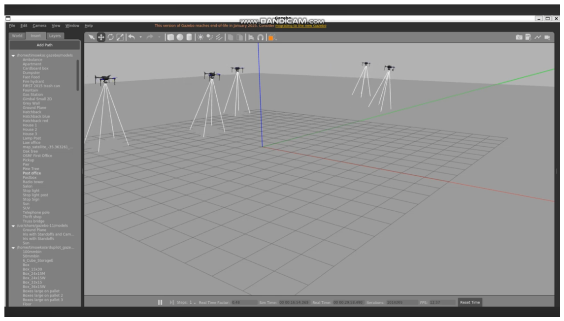
Simulation experiments were conducted in Gazebo, AirSim, and PX4 software-in-the-loop environments. The scenarios represented open and urban-like spaces with static and dynamic obstacles, limited visibility, GPS degradation or intermittent loss, and communication latency and jitter. The simulation campaign included single-UAV and multi-UAV cases and introduced communication failures and node loss to examine decentralized resilience. Examples of the Gazebo experiments for one, three, and five vehicles are shown in Figure 8, Figure 9 and Figure 10.
Figure 11.
Multi-UAV simulation with five vehicles.
5.2. Field Environment and Flight Conditions
Field experiments were conducted in a controlled open area of approximately m. Flights were performed between 2 and 15 m above ground at speeds between 0.5 and 3 m/s. The scenarios included static poles, trees, and artificial barriers. Designated regions with RF shielding and multipath conditions were used to create GPS-degraded zones. The communication system used a dual-band 2.4/5 GHz Wi-Fi mesh. During the reported experiments, CPU load on the Raspberry Pi 4 was approximately 45–65%, while GPU load on the Jetson Nano during SLAM processing was approximately 30–50%.
The field campaign included four scenario classes: obstacle-aware navigation, formation and swarm coordination, GPS-degraded operation, and communication stress testing. The draft reports field flights with 2–3 simultaneously exchanging UAVs, while the overall architecture and simulation evaluation considered up to five UAVs. This distinction is retained here because the field and simulation scales should not be conflated.
Figure 12.
QGroundControl interface during field-flight monitoring.
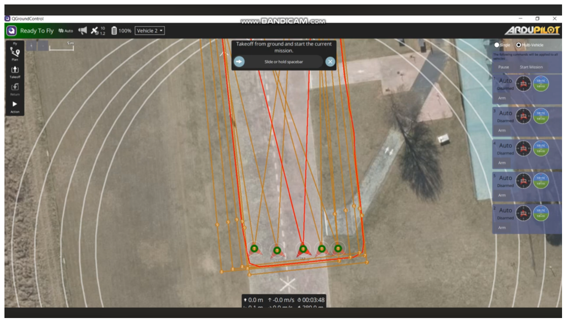
Figure 13.
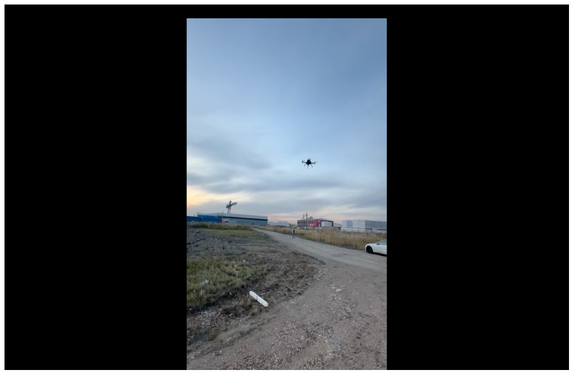
Representative field test with multiple UAVs.
5.3. Evaluation Metrics
Four primary metrics were used: message transmission delay for network performance; position RMSE and its empirical percentile for localization; end-to-end reaction time for obstacle avoidance; and mission success rate for system-level operation. Simulation and field communication results were summarized separately. Numerical analysis and plotting were performed using Python with NumPy, SciPy, and Matplotlib.
6. Results
6.1. Mesh-Network Performance
Figure 14 shows the empirical cumulative distribution of inter-UAV message delays. In simulation, the reported minimum, mean, and maximum delays were approximately 30, 45–55, and 75 ms, respectively. The field measurements were approximately 35, 50–60, and 80 ms. The reported 95th-percentile delay was below 70 ms in simulation and below 75 ms in the field tests. More than 95% of packets were reported to arrive within approximately 75–80 ms in both environments.
These measurements are consistent with the bounded-delay assumption used in the mathematical model. The results do not establish scalability to substantially larger networks, but they indicate that the tested mesh configuration provided sufficiently regular delays for the local coordination algorithm used in the experiments.

Table 1.
Measured mesh-network communication delays.
| Metric | Simulation | Field |
|---|---|---|
| Minimum delay (ms) | ∼30 | ∼35 |
| Mean delay (ms) | 45–55 | 50–60 |
| Maximum delay (ms) | ∼75 | ∼80 |
| 95th percentile (ms) |
6.2. Localization Under Degraded GPS
The localization results are shown in Figure 15. GPS-only positioning yielded a mean RMSE of approximately 0.9–1.3 m, with the 95th-percentile error exceeding 1.5 m. In contrast, the SLAM+IMU configuration achieved a reported mean RMSE of 0.32–0.48 m and maintained a 95th-percentile error below 0.5 m.
Table 2.
Localization accuracy under degraded GPS conditions.
| Navigation mode | Mean RMSE (m) | 95th percentile (m) |
|---|---|---|
| GPS-only | 0.9–1.3 | |
| SLAM + IMU | 0.32–0.48 |
6.3. Obstacle-Response Time
The decomposition of the obstacle-response time is shown in Figure 16. Based on the component ranges reported in the draft, the theoretical aggregate is below approximately 0.95 s. Direct measurements in the results section give a total response time of approximately 0.5–0.6 s, which is below the 1 s threshold used for the evaluation.
The largest contribution was associated with sensor processing and state estimation. This observation is important for practical optimization because reducing network latency alone is unlikely to provide a comparable reduction in end-to-end response time once communication delay is already within the measured 30–80 ms range.
6.4. Mission Success
The reported scenario-specific success rates are given in Table 3. Simulation success rates were 92.5% for obstacle navigation, 93.8% for formation coordination, 91.2% for GPS-degraded operation, and 90.5% for communication stress testing. The corresponding field values were 90.0%, 91.7%, 89.3%, and 88.9%, respectively.
The source draft also reports that 27 of 30 field missions were completed without operator intervention, corresponding to an overall field completion rate of 90.0%. This value is consistent with the stated overall 90% level but not with the broader wording in the original draft that all individual field series exceeded 90%. The scenario-specific measurements are therefore reported without that stronger claim.
7. Discussion
The experimental results support the central design premise of the proposed system: a multi-UAV architecture can retain useful local autonomy when centralized dependencies are reduced and when perception, state estimation, and coordination are distributed across the vehicles. The benefit is not demonstrated through a single performance number. Rather, the network, localization, reaction-time, and mission-level measurements form a connected chain. Communication delays remain within the range assumed by the coordination model, local state estimation remains substantially more accurate than GPS-only positioning in the degraded scenarios, and the end-to-end obstacle-response time remains below the evaluation threshold.
The positioning results are particularly relevant to decentralized operation. A swarm that relies on a central absolute position estimate is vulnerable to failures in that source, whereas local visual-inertial estimation allows each vehicle to continue forming its own short-horizon state estimate. The reported 0.32–0.48 m mean RMSE is also consistent with the broader literature showing that visual-inertial methods can provide useful state estimates for autonomous aerial motion [8,9]. The present experiments do not, however, establish that the same accuracy will hold across textureless environments, rapid illumination changes, or extended GNSS outages.
The network measurements illustrate a related trade-off. The field delay range of roughly 35–80 ms is sufficiently small relative to the sampling period used by the local controller for the reported coordination experiments. More importantly, the measurements do not exhibit the large delay tail that would be especially problematic for local consensus and collision-avoidance updates. At the same time, the architecture should not be interpreted as insensitive to network degradation. The model explicitly contains time-varying connectivity and delayed state estimates, and prolonged partitioning or severe congestion would eventually isolate parts of the swarm. The role of the mesh is therefore to reduce dependence on a fixed central path, not to guarantee connectivity under all radio conditions.
The reaction-time results suggest that onboard computation is currently a more promising optimization target than small reductions in message latency. The original measurements allocate a relatively modest portion of the response budget to networking compared with sensing and state-estimation processing. This finding is consistent with the use of companion computers for high-level computation: the flexibility of onboard processing is valuable, but the processing pipeline must remain bounded enough for safety-critical decisions. Current ROS 2/PX4 integration practices are aligned with this architectural separation [7].
The mission results show that the architecture was functional in the tested conditions, but they should be interpreted cautiously. The field campaign used only 2–3 simultaneously communicating UAVs, and the reported campaign contained 30 missions. Simulation tests extended to five UAVs. These numbers are sufficient to demonstrate integrated operation but are not sufficient to establish large-scale swarm scalability. Communication load, collision-avoidance complexity, computation demand, and topology dynamics can all grow with the number of agents. Previous swarm studies have identified precisely these scaling effects as major challenges [1,3,4].
The system also remains largely homogeneous: the experimental aircraft use similar sensing and computing capabilities. Heterogeneous swarms containing vehicles with different payloads, link budgets, or computational capacity could provide operational benefits but would require extensions to the coordination and task-allocation logic. Similarly, the current controller combines interpretable local rules and safety constraints rather than a learned multi-agent policy. This choice improves transparency and simplifies deployment, but future work could investigate carefully bounded integration with multi-agent reinforcement learning while retaining explicit collision and communication constraints [6].
Finally, the security mechanisms included in the implementation should be distinguished from a complete cybersecurity evaluation. Encryption, authentication, message-integrity checks, and protocol hardening are appropriate design measures, but the present experiments did not quantify resistance to active attacks. Prior work on MAVLink security shows why this distinction matters for UAV systems exposed to hostile or untrusted networks [11]. A dedicated security evaluation would therefore be needed before the system could be characterised as cyber-resilient in operational deployments.
8. Limitations
The main limitation is experimental scale. Although the simulated swarm includes up to five UAVs, the field tests reported in the source material involved 2–3 simultaneously interacting vehicles. The study therefore demonstrates feasibility and integrated performance rather than large-swarm scalability. The field evaluation was conducted in a controlled area, and the degradation of GPS was created in designated regions rather than observed across a broad set of naturally occurring environments. The field platform was also homogeneous, and the current coordination logic does not address heterogeneous capabilities or dynamic task allocation. Finally, the source draft does not provide the complete mission-by-mission sample counts for each scenario or the numerical confidence intervals, so statistical comparisons beyond the reported success percentages are not claimed here.
9. Conclusions
This paper presented a decentralized three-layer control architecture for UAV swarms in which stabilization, onboard computation, and inter-UAV communication are organized as cooperating local functions. The implementation combined a conventional flight controller with Raspberry Pi 4 or Jetson Nano companion computing, visual and LiDAR sensing, visual-inertial SLAM, ROS 2, MAVLink-based control integration, and a peer-to-peer Wi-Fi mesh. Swarm coordination relied on local neighbour information, separation–alignment–cohesion behaviour, predictive intent exchange, and barrier-function-based collision constraints.
The reported experiments show that the tested architecture maintained mesh communication delays of approximately 30–80 ms, achieved 0.32–0.48 m mean localization RMSE under degraded GPS, and produced direct obstacle-response measurements of approximately 0.5–0.6 s. Across the reported field campaign, 27 of 30 missions were completed without operator intervention. These measurements indicate that distributing sensing and decision-making can reduce dependence on a central coordinator while retaining acceptable local control performance in the tested conditions.
The results should nevertheless be interpreted within the limits of the evaluation. The field campaign involved only 2–3 simultaneously communicating UAVs, whereas simulation extended to five vehicles, and the experimental swarm was homogeneous. Future work should therefore focus on larger field deployments, heterogeneous agents, more demanding communication conditions, improved onboard computing, 4D LiDAR, and learning-based coordination methods that preserve explicit safety constraints.
Author Contributions
Conceptualization, G.B. and Z.K.; methodology, G.B. and Z.K.; software, Z.K., F.R. and G.B.; validation, G.B. and Z.K.; investigation, D.N., F.R., G.B. and Z.K.; writing—original draft preparation, D.N., Z.K. and F.R.; writing—review and editing, D.N., F.R. G.B. and Z.K.; supervision, Z.K., G.B. and N.R.; project administration, N.R. All authors have read and agreed to the published version of the manuscript.
Funding
This research was funded by the Science Committee of the Ministry of Education and Science of the Republic of Kazakhstan, grant number .
Institutional Review Board Statement
Not applicable. The study did not involve human participants or animals.
Acknowledgments
The authors acknowledge the support associated with the experimental and development activities reported in this study.
Conflicts of Interest
The authors declare no conflict of interest.
References
- Campion, M.; Ranganathan, P.; Faruque, S. UAV swarm communication and control architectures: a review. Journal of Unmanned Vehicle Systems 2019, 7, 93–106. [CrossRef]
- Tahir, A.; B"oling, J.; Haghbayan, M.H.; Toivonen, H.T.; Plosila, J. Swarms of unmanned aerial vehicles—A survey. Journal of Industrial Information Integration 2019, 16, 100106. [CrossRef]
- Coppola, M.; McGuire, K.N.; De Wagter, C.; de Croon, G.C.H.E. A Survey on Swarming With Micro Air Vehicles: Fundamental Challenges and Constraints. Frontiers in Robotics and AI 2020, 7, 18. [CrossRef]
- Chen, X.; Tang, J.; Lao, S. Review of Unmanned Aerial Vehicle Swarm Communication Architectures and Routing Protocols. Applied Sciences 2020, 10, 3661. [CrossRef]
- Gong, Z.; Liu, P.; Wen, F.; Ying, R.; Ji, X.; Miao, R.; Xue, W. Graph-Based Adaptive Fusion of GNSS and VIO Under Intermittent GNSS-Degraded Environment. IEEE Transactions on Instrumentation and Measurement 2021, 70, 1–16. [CrossRef]
- Batra, S.; Huang, Z.; Petrenko, A.; Kumar, T.; Molchanov, A.; Sukhatme, G.S. Decentralized Control of Quadrotor Swarms with End-to-end Deep Reinforcement Learning. In Proceedings of the Proceedings of the 5th Conference on Robot Learning. PMLR, 2022, Vol. 164, pp. 576–586.
- PX4 Development Team. ROS 2. PX4 User Guide, 2026. Accessed 15 September 2026.
- Qin, T.; Li, P.; Shen, S. VINS-Mono: A Robust and Versatile Monocular Visual-Inertial State Estimator. IEEE Transactions on Robotics 2018, 34, 1004–1020. [CrossRef]
- Campos, C.; Elvira, R.; Gómez Rodríguez, J.J.; Montiel, J.M.M.; Tardós, J.D. ORB-SLAM3: An Accurate Open-Source Library for Visual, Visual–Inertial, and Multimap SLAM. IEEE Transactions on Robotics 2021, 37, 1874–1890. [CrossRef]
- Li, T.; Hailes, S.; Julier, S.; Liu, M. UAV-based SLAM and 3D reconstruction system. In Proceedings of the 2017 IEEE International Conference on Robotics and Biomimetics (ROBIO), 2017, pp. 2496–2501. [CrossRef]
- Allouch, A.; Cheikhrouhou, O.; Koubaa, A.; Khalgui, M.; Abbes, T. MAVSec: Securing the MAVLink Protocol for Ardupilot/PX4 Unmanned Aerial Systems. In Proceedings of the 2019 15th International Wireless Communications and Mobile Computing Conference (IWCMC), 2019, pp. 621–628. [CrossRef]
- Betcher-Sbrolla, G.; Lopez-Aguilera, E.; Garcia-Villegas, E. Analysis and Proposal of Strategies for the Management of Drone Swarms Through Wi-Fi Technologies. Drones 2025, 9, 584. [CrossRef]
- Reynolds, C.W. Flocks, Herds, and Schools: A Distributed Behavioral Model. In Proceedings of the Proceedings of the 14th Annual Conference on Computer Graphics and Interactive Techniques, 1987, pp. 25–34. [CrossRef]
- Olfati-Saber, R. Flocking for Multi-Agent Dynamic Systems: Algorithms and Theory. IEEE Transactions on Automatic Control 2006, 51, 401–420. [CrossRef]
Figure 1.
Three-layer decentralized UAV swarm architecture comprising stabilization, computation, and networking layers.
Figure 1.
Three-layer decentralized UAV swarm architecture comprising stabilization, computation, and networking layers.
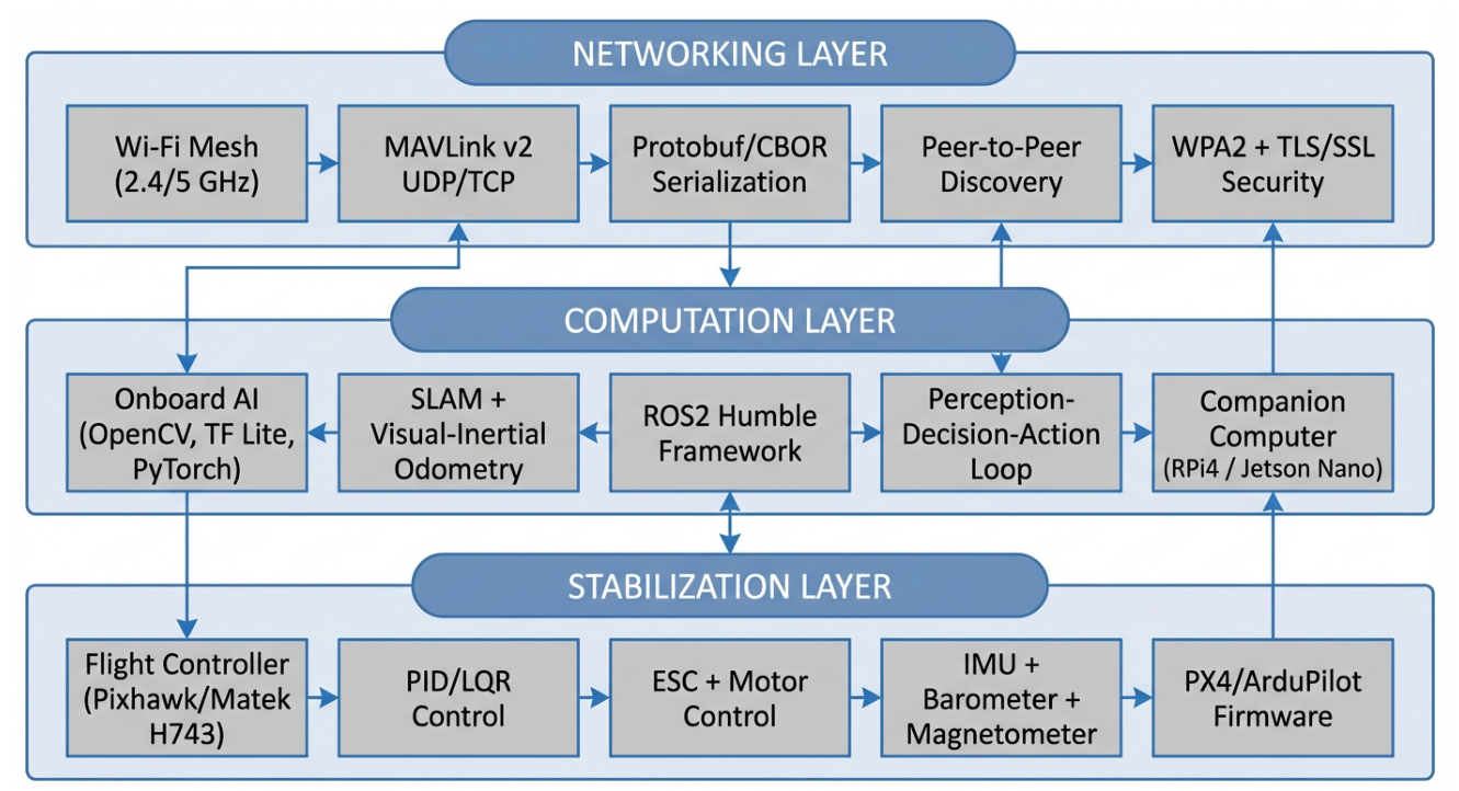
Figure 2.
Component layout of the F450-based experimental UAV.
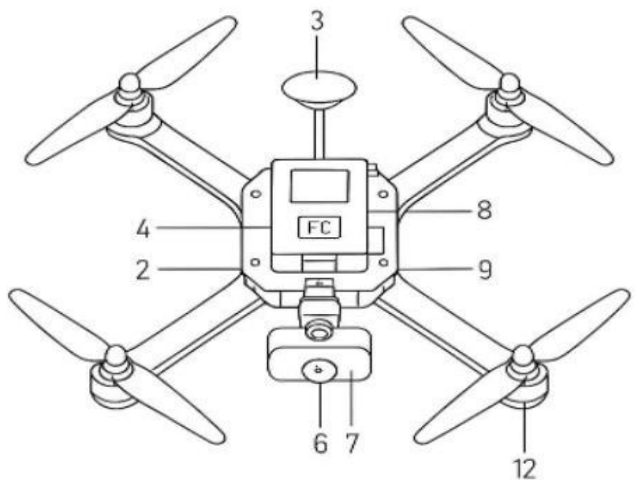
Figure 3.
Experimental UAV platform used in the field evaluation.
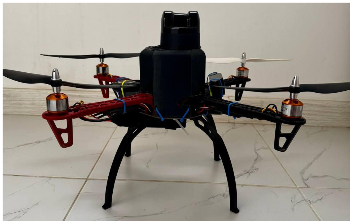
Figure 4.
Operating principle of the Unitree L2 LiDAR used for local obstacle perception.
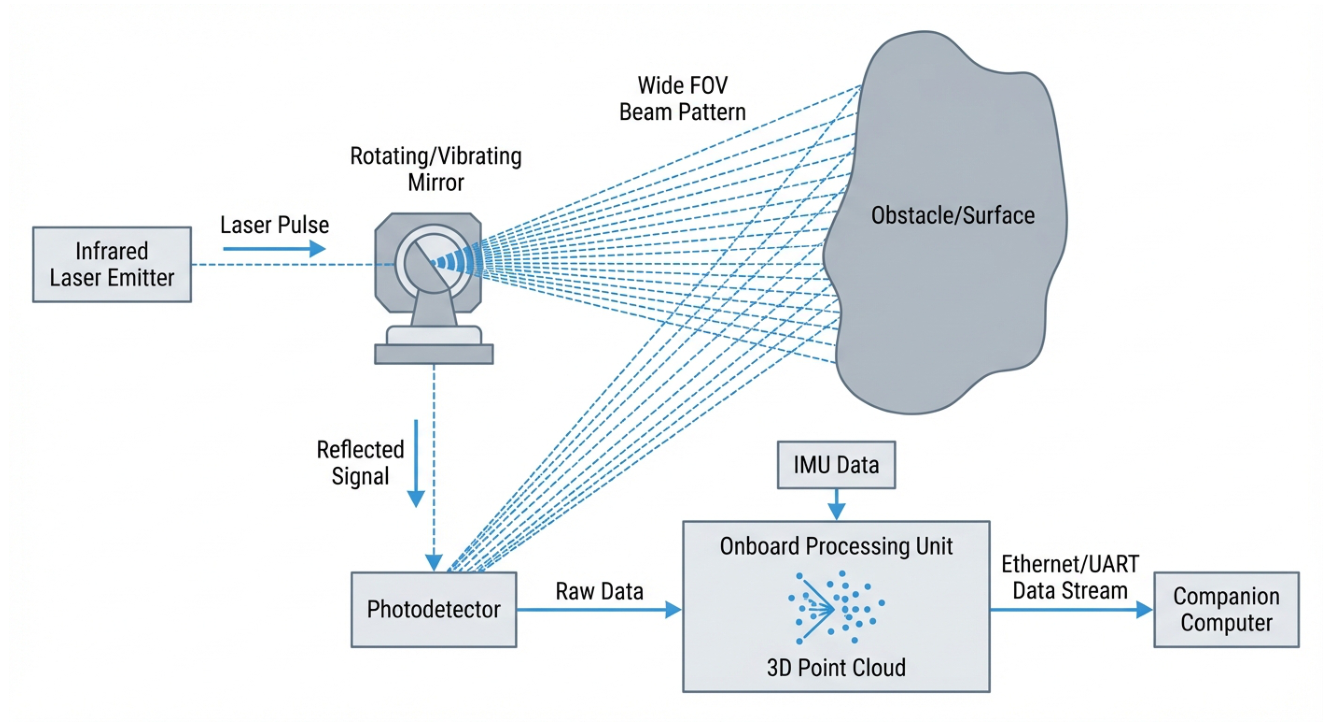
Figure 5.
Onboard RPi/Jetson–flight-controller control loop used by each UAV.
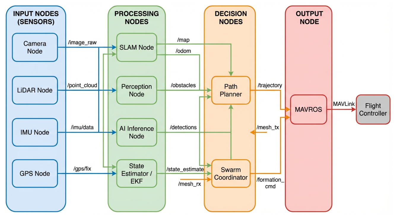
Figure 6.
Logical organization of ROS 2 nodes and data flows between onboard sensing, processing, decision-making, and flight control.
Figure 6.
Logical organization of ROS 2 nodes and data flows between onboard sensing, processing, decision-making, and flight control.
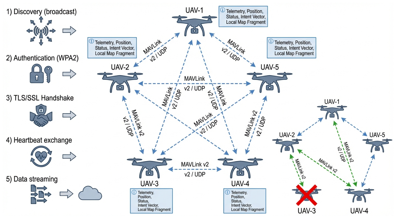
Figure 7.
Mesh communication structure and dynamic topology used for decentralized information exchange.
Figure 7.
Mesh communication structure and dynamic topology used for decentralized information exchange.
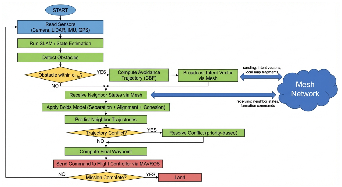
Figure 8.
Representative launch state in the Gazebo simulation environment.
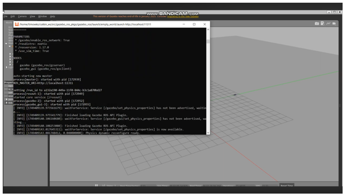
Figure 9.
Obstacle-avoidance simulation with one UAV.
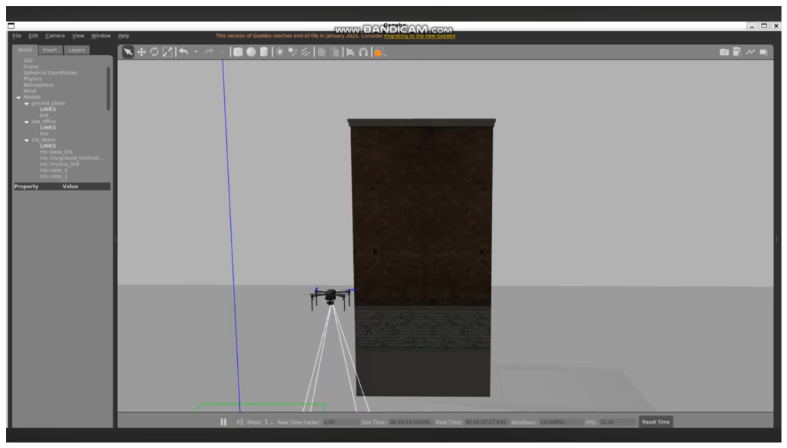
Figure 10.
Multi-UAV simulation with three vehicles.
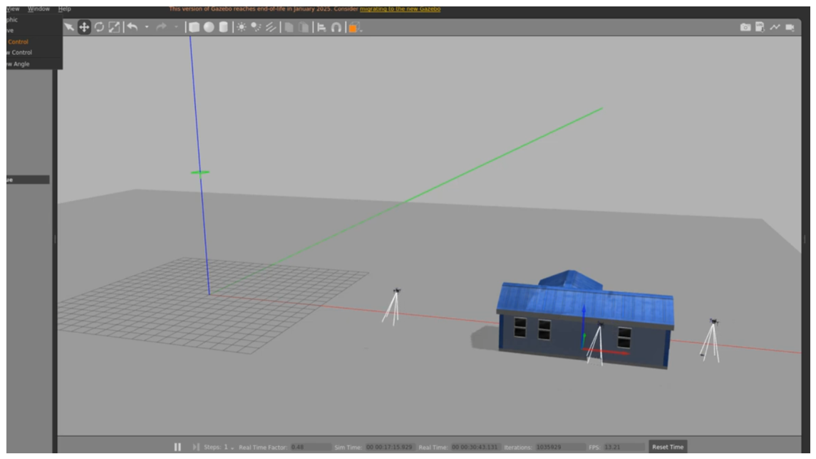
Figure 14.
Empirical cumulative distribution of message transmission delays for simulation and field measurements.
Figure 14.
Empirical cumulative distribution of message transmission delays for simulation and field measurements.
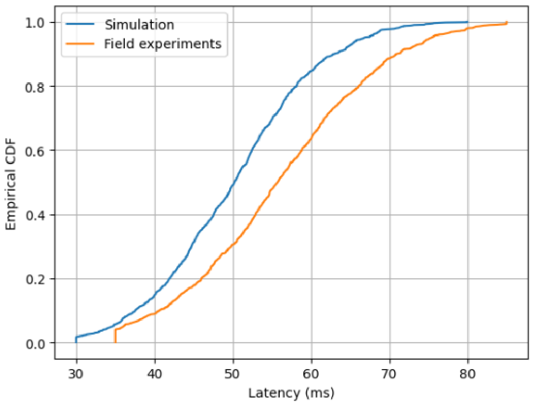
Figure 15.
Empirical cumulative distributions of localization error for GPS-only and SLAM+IMU operation under degraded GPS conditions.
Figure 15.
Empirical cumulative distributions of localization error for GPS-only and SLAM+IMU operation under degraded GPS conditions.
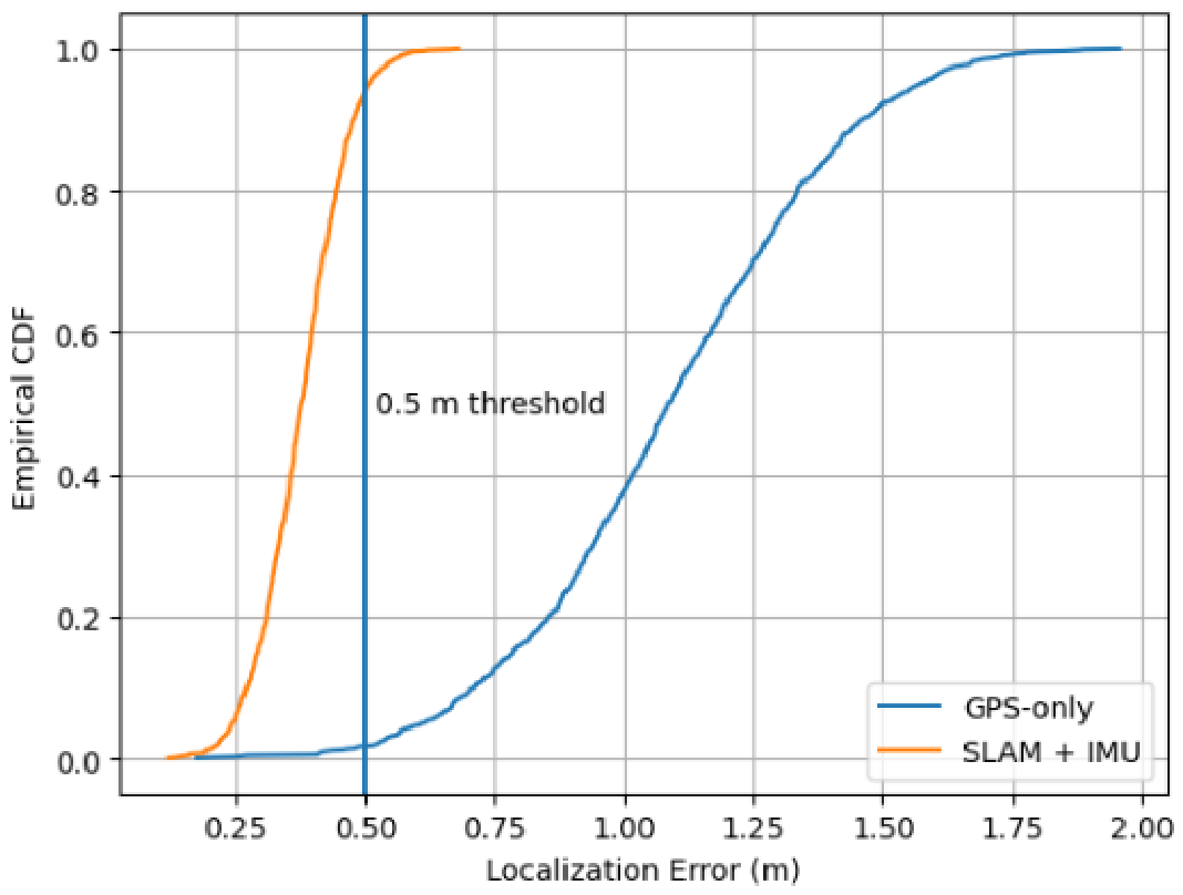
Figure 16.
Breakdown of total obstacle-response time into sensing, processing, networking, and control components.
Figure 16.
Breakdown of total obstacle-response time into sensing, processing, networking, and control components.
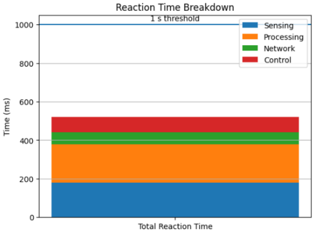
Table 3.
Mission success rates by scenario.
| Scenario | Simulation success (%) | Field success (%) |
|---|---|---|
| Navigation with obstacles | 92.5 | 90.0 |
| Formation coordination | 93.8 | 91.7 |
| GPS-degraded operation | 91.2 | 89.3 |
| Communication stress test | 90.5 | 88.9 |
Disclaimer/Publisher’s Note: The statements, opinions and data contained in all publications are solely those of the individual author(s) and contributor(s) and not of MDPI and/or the editor(s). MDPI and/or the editor(s) disclaim responsibility for any injury to people or property resulting from any ideas, methods, instructions or products referred to in the content. |
© 2026 by the authors. Licensee MDPI, Basel, Switzerland. This article is an open access article distributed under the terms and conditions of the Creative Commons Attribution (CC BY) license (http://creativecommons.org/licenses/by/4.0/).
Copyright: This open access article is published under a Creative Commons CC BY 4.0 license, which permit the free download, distribution, and reuse, provided that the author and preprint are cited in any reuse.