

Submitted:
24 September 2026
Posted:
28 September 2026
You are already at the latest version
Abstract
The catalytic utilization of carbon dioxide (CO2) and methane (CH4) provides a sustainable pathway for the simultaneous conversion of two greenhouse gases into value-added fuels and chemicals. This study presents a steady-state simulation of a dimethyl ether (DME) production process using an integrated three-reactor system developed in ChemCAD. The process comprises dry reforming of methane over a Ni/Al2O3 catalyst to generate synthesis gas, catalytic methanol synthesis over a Cu/ZnO/Al2O3 catalyst, and methanol dehydration over γ-Al2O3 to produce DME. Thermodynamic calculations were performed using the Non-Random Two-Liquid (NRTL) model coupled with the latent-heat enthalpy method, while reactor performance was represented using literature-based Arrhenius kinetic expressions. The downstream process incorporated staged heat recovery, flash separation, gas compression, chilled condensation, and a primary distillation column for crude DME recovery. Under the simulated operating conditions, the integrated process produced 237.05 kg h⁻¹ of crude DME, with the primary distillation column recovering up to 93% of the DME present in the condensed liquid stream, leaving only 0.03 kg h⁻¹ in the column bottoms. The combination of staged compression and low-temperature flash separation significantly enhanced DME recovery by promoting the condensation of condensable species while rejecting non-condensable gases. The proposed process demonstrates the technical feasibility of integrating reaction engineering and separation technologies for efficient DME production from CO2 and CH4 and establishes a robust process platform for future optimization and industrial-scale implementation.
Keywords:
dimethyl ether
; carbon dioxide utilization
; dry reforming of methane
; ChemCAD
1. Introduction
The global imperative to reduce atmospheric carbon dioxide concentrations has accelerated interest in technologies that convert CO2 from an environmental liability into a chemical feedstock. Among the emerging pathways for CO2 valorization, the production of oxygenated fuels and chemical intermediates represents one of the more commercially tractable routes, combining environmental benefit with economic value [1,2]. Dimethyl ether (DME, CH3OCH3) has attracted substantial attention in this context. It is the simplest ether and carries physical properties remarkably similar to liquefied petroleum gas (LPG), including a boiling point of −24.8°C at atmospheric pressure and a vapour pressure of approximately 5.1 bar at 20°C. These make it efficient within existing LPG infrastructure without modification, which confers an advantage over many other alternative fuels that demand entirely new distribution networks [3]. DME has a cetane number of 55–60, significantly higher than diesel fuel (40–55), making it an effective diesel substitute in compression-ignition engines with near-zero particulate emissions owing to its oxygen content and absence of carbon-carbon bonds [4]. Its calorific value, at approximately 28.4 MJ kg⁻¹, is lower than diesel on a mass basis but competitive when the cleaner combustion is taken into account. DME also serves as a methylating agent in chemical synthesis, a propellant in aerosol products, and a refrigerant, while its potential as a hydrogen carrier for fuel cell applications has also been explored [5].
The conventional industrial route to DME is the two-step process, which follows that methanol is first synthesized from syngas (Eq.1) at 250–280°C and 50–80 bar over a Cu/ZnO/Al2O3 catalyst and subsequently dehydrated over solid acid catalysts such as γ-alumina (Eq.2) at 250–350°C [6]. Syngas itself is predominantly derived from steam methane reforming (SMR) of natural gas, a process that is net carbon positive. The growing availability of CO2 captures from power generation, and industrial processes has prompted investigation of CO2-containing feeds as alternatives. Dry reforming of methane (Eq.3) offers the singular advantage of consuming two greenhouse gases simultaneously, producing a syngas with a H2:CO ratio of unity, which is particularly suitable for subsequent downstream processing [7,8].
CO + 2H₂ → CH₃OH
2CH3OH → CH3OCH3 + H2O
Despite the thermodynamic attractiveness of DRM, industrial implementation remains challenging. The reaction is highly endothermic, requiring temperatures of 800–950°C, and the resulting syngas H2:CO ratio of approximately 1 is lower than the 2:1 stoichiometric ratio required for methanol synthesis. This requires either a water-gas shift (WGS) adjustment step or the acceptance of a CO-rich syngas entering the methanol reactor, with implications for conversion efficiency and selectivity [9]. An alternative is the integration of CO2 co-hydrogenation reactions within the methanol synthesis reactor itself, exploiting both CO and CO2 hydrogenation pathways. Published simulation studies have demonstrated that such integrated approaches are technically feasible, though economic viability is strongly sensitive to natural gas and electricity prices, catalyst costs, and the valuation assigned to CO2 [10,11].
Process simulation is an indispensable tool in the early-stage evaluation of such routes. It allows rigorous material and energy balances to be established before experimental campaigns and permits rapid sensitivity analysis across a wide parameter space. Several simulation platforms have been applied to DME-related processes. E-Moghaddam et al. [12] analyzed different synthesis routes for CH3OH and DME from syngas utilizing Aspen Plus. The authors deployed kinetic models for both methanol and DME production while assessing the efficiency of the downstream processes. Similarly, Dieterich et al. [13] compared four renewable DME production pathways from CO₂ and H₂ using Aspen Plus and process heat integration. They found considerable differences in energy and economic performance between direct and indirect configurations. Fedeli et al. [14] developed a rigorous Aspen Plus flowsheet integrating reforming, DME synthesis and downstream purification and further optimized the separation section using technical, economic and sustainability indicators.
ChemCAD (Chemstations Inc.) is a rigorous steady-state process simulator with proven capabilities for petroleum, gas processing, and chemical plant design. Its NRTL thermodynamic package is well-established for polar component systems involving methanol, water, and ethers. The platform’s kinetic reactor module (KREA) supports user-defined reaction kinetics with axial temperature profiles, making it suitable for simulating the non-isothermal behaviour of both the methanol synthesis and dehydration reactors. To the best of the authors’ knowledge, no published study has reported a complete three-stage DRM-methanol-DME process simulation in ChemCAD incorporating all process units from feed mixing through to distillation product recovery.
The present work addresses this gap. We report a steady-state ChemCAD simulation of a complete process chain encompassing: (i) dry reforming of methane, modelled as an equilibrium reactor; (ii) methanol synthesis from the resulting syngas, modelled with kinetic equations from the Vanden Bussche and Froment [15] mechanism; (iii) methanol dehydration to DME over γ-Al₂O₃, modelled with the kinetics of Bercic and Levec [13]; and (iv) product separation and purification via flash separation and two distillation columns. Mass and energy balances are presented for all unit operations, and the results are benchmarked against published experimental and simulation data. The study culminates in a preliminary techno-economic discussion that identifies the key cost drivers for this process configuration and outlines priority areas for optimization.
2. Materials and Methods
2.1. Overall Process Concept
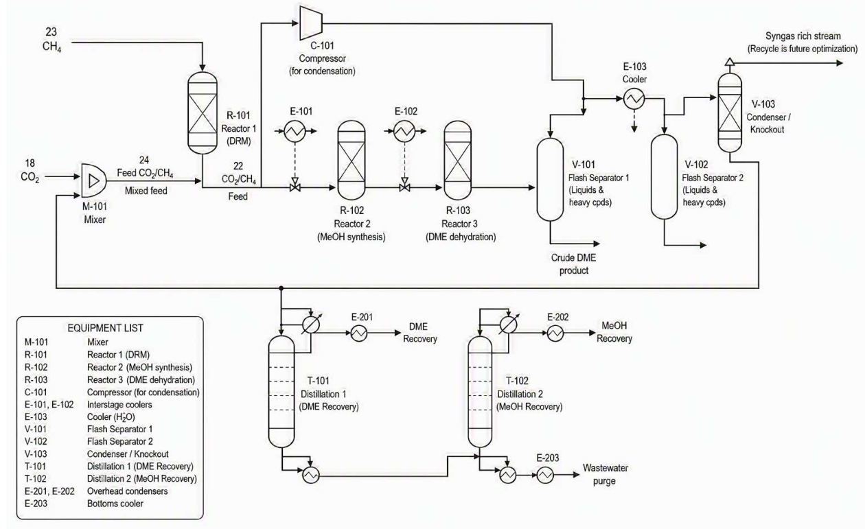
The process evaluated in this study consists of three chemically distinct reaction stages connected by heat integration and separation equipment. Figure 1 shows the ChemCAD process flowsheet as developed for this simulation. Carbon dioxide and methane are fed to a mixing unit at a CO2:CH4 molar ratio of 1:1, consistent with the stoichiometry of the DRM reaction. The mixed feed enters a fired equilibrium reactor (the DRM reactor, R-101-DRM) operating at thermodynamic equilibrium at elevated temperature. The hot syngas product is then cooled in a heat exchanger train before entering the CH3OH synthesis reactor (R-102-MeOH), a kinetic plug-flow reactor. The methanol-containing reactor effluent proceeds through further cooling, compression, and a primary flash separation to recover condensable products. The liquid phase, containing methanol, water, residual CO2, and dissolved gases, is fed to the dehydration reactor (R-103-DRM dehydration), where MeOH is conventionally converted over solid acid catalyst to DME. The crude DME mixture then passes through a two-column distillation sequence to recover DME at the required purity and separate methanol for recycling. The process is intended as a once-through conversion with unconverted syngas exiting the top of the first flash separator (V-101) as a gas-phase stream rich in H2, CO, CH4, and CO2. As annotated on the flowsheet, this stream is designated for future recycle optimization, representing a significant lever for improving overall carbon utilisation efficiency. The thermodynamic specifications were calibrated as presented in Table 1.
2.2. Dry Reforming of Methane
The feed consisted of methane and carbon dioxide mixed at the specified design ratio before entering the dry reforming reactor. Reactor 1 (R-101-DRM) represented the dry reforming of methane over a Ni/Al2O3 catalyst to generate synthesis gas. The reformate entered Reactor 2 (R-102-MeOH) where methanol was synthesised over a Cu/ZnO/Al2O3 catalyst using a kinetic plug-flow reactor. The methanol-rich stream was subsequently fed to Reactor 3 (R-103-DRM dehydration) where methanol dehydration over γ-Al2O3 produced dimethyl ether and water. Reactor effluent was cooled and routed through two flash separation stages. The first flash removed condensed liquid while the vapour was compressed and chilled to enhance DME condensation before a second flash separator. The combined liquid stream entered a rigorous distillation column for DME purification, followed by a second distillation column for methanol recovery and recycle [16]. The equilibrium calculation in ChemCAD minimises the Gibbs free energy of the system simultaneously across all possible reactions, including the primary DRM reaction, the reverse water-gas shift (Eq.4), and the Boudouard reaction (Eq.5). No solid carbon phase was included in the phase equilibrium, which is a common modelling simplification acceptable when operating above the carbon deposition boundary [17].
RWGS: CO2 + H₂ ⇌ CO + H₂O
2CO ⇌ CO2 + C
2.3. Methanol Synthesis
Methanol synthesis was modelled using the ChemCAD KREA (kinetic reactor 2) unit. The reactor operates as a plug-flow reactor (PFR) and employs the kinetic rate expressions of Vanden Bussche and Froment [15], which account for three parallel reactions (Eq.6 to 8) on the Cu/ZnO/Al₂O₃ catalyst surface:
R1: CO2 + 3H2⇌ CH3OH + H2O ΔH° = −49.5 kJ mol−1
R2: CO2 + H2⇌ CO + H2O ΔH° = +41.2 kJ mol−1 (RWGS)
R3:CO + 2H2⇌ CH3OH ΔH° = −90.7 kJ mol−1
The extracted simulation data indicate an inlet temperature of approximately 227°C (500 K) with reactor pressure of 44 bar, consistent with published operating windows for methanol synthesis (220–280°C, 30–50 bar) [10].
2.4. Separation System
The reactor effluent was first cooled using cooling water before entering the primary flash separator. Vapour leaving the separator was compressed and further cooled using chilled water to increase DME condensation before a secondary flash separator (V-102). A rigorous staged distillation column (T-101) recovered DME as the overhead product while methanol and water were withdrawn as bottoms. A second distillation (T-102) column recovered methanol as an overhead recycle stream and produced a water-rich bottoms stream suitable for purge. Material and energy balances were evaluated for each unit operation. Product distribution, DME recovery, methanol recovery, utility demand and separation performance were obtained from the converged simulation and used for subsequent techno-economic assessment.
3. Simulation Methodology
3.1. Software and Thermodynamic Framework
The NRTL (Non-Random Two-Liquid) activity coefficient model was selected for the liquid-phase fugacity calculation, with the Redlich-Kwong equation of state applied to the vapour phase. The NRTL model is well-established for the methanol-water-DME ternary system, and ChemCAD 8 binary interaction parameters for this system are taken from the built-in databank, which has been validated against published VLE data [18]. Enthalpy was computed using the latent heat method (latent heat of vaporization from the ChemCAD library), which is appropriate for streams where vaporization and condensation dominate the thermal load, as is the case in the distillation and flash sections. For the high-temperature DRM reactor section, a local thermodynamic override to the Soave-Redlich-Kwong (SRK) equation of state was applied to better represent the H2-CO2-CH4 gas phase at elevated temperature and moderate to high pressure. The simulation convergence criterion applied a tolerance of 0.001 on temperature, pressure, vapour fraction, enthalpy, and flow rate simultaneously across all recycle streams and unit operations. The maximum number of iterations for the outer recycle loop was set to 80, consistent with the default ChemCAD configuration. The simulation was confirmed to have achieved convergence at the reported conditions. The overall system is as presented in Figure 1.
Figure 1.
Flow diagram of the DME synthesis process.
3.2. Feed Specification and Basis
The simulation basis is 1,000 kmol/h of combined CO2 and CH4 feed, fed in equimolar proportions (500 kmol/h each) at 25°C and 1 bar. This basis corresponds to approximately 88 t h-1 of raw feed. A nitrogen purge stream is included to maintain the simulation’s convergence stability and to represent inert trace components that would be present in a real CO2 capture stream. The CO2 feed and CH4 feed are mixed in a single mixer before preheating to the DRM reactor inlet temperature. No Sulphur species or higher hydrocarbons are included in the feed, which is equivalent to assuming a pre-treated and purified feed gas.
3.3. Reactor Modelling
Table 2 summarizes the reactor types, model approaches, and key operating conditions employed in the simulation. The DRM reactor (R-101-DRM) was modelled using a kinetic plug flow reactor (PFR) rather than an equilibrium (Gibbs) reactor. A kinetic reactor was selected because the DRM reaction is strongly influenced by catalyst activity, reaction kinetics and residence time, making an equilibrium-based approach less representative of practical industrial operation. The PFR model enables the incorporation of experimentally derived kinetic parameters and provides a more realistic prediction of methane and carbon dioxide conversion over a fixed-bed catalytic reactor. The reactor was simulated under steady-state conditions at 800 °C and 3 atm, employing a Ni/Al₂O₃ catalyst represented through an Arrhenius-type kinetic expression. Temperature was held constant by the fired heater unit, which calculated the required fuel duty to maintain the set-point.
The methanol synthesis reactor was modelled as a kinetic plug flow reactor (PFR) using the intrinsic kinetic model developed by Vanden Bussche and Froment. Unlike equilibrium-based reactor models, the kinetic PFR accounts for finite reaction rates, catalyst activity, residence time and adsorption phenomena, thereby providing a more representative description of industrial fixed-bed methanol synthesis reactors. The Vanden Bussche–Froment model remains one of the most extensively applied kinetic formulations for methanol synthesis and has been adopted in numerous process simulation and reactor design studies because of its ability to accurately predict methanol formation over a broad range of operating conditions [19]. The kinetic model simultaneously considers carbon dioxide hydrogenation, carbon monoxide hydrogenation and the reverse water-gas shift (RWGS) reaction using Langmuir–Hinshelwood–Hougen–Watson (LHHW) rate expressions. The reaction rates implemented are expressed as in Eq.9.
The CO2 hydrogenation follows Eq. 10,
For RWGS,
where ri represents the intrinsic reaction rate, ki is the Arrhenius temperature-dependent rate constant, fidenotes the fugacity of the reacting species, ηi is the approach-to-equilibrium factor for each reaction, and Den represents the adsorption denominator accounting for competitive adsorption of reactants and products on the catalyst surface. The adsorption term incorporates the inhibiting effects of strongly adsorbed species and enables accurate prediction of catalyst behaviour under varying temperatures, pressures and reactant compositions.
The methanol dehydration reactor was similarly modelled as a kinetic plug flow reactor to simulate the catalytic conversion of methanol into dimethyl ether (DME) over a γ-Al2O3 catalyst. A kinetic reactor was selected because methanol dehydration is governed by catalyst-controlled reaction kinetics and competitive adsorption rather than thermodynamic equilibrium alone. Consequently, the kinetic approach provides a more realistic representation of industrial fixed-bed dehydration reactors and enables prediction of catalyst utilization, reaction rates and temperature profiles along the reactor length.
The dehydration reaction was represented using the Bercic and Levec kinetic model, which is one of the most widely adopted LHHW formulations for methanol dehydration over γ-Al2O3 catalysts. The intrinsic reaction rate is given by Eq.12.
where, k4 is the Arrhenius rate constant, KMeOH and are adsorption equilibrium constants for methanol and water, respectively, while Ci denotes the concentration of each component. The denominator accounts for competitive adsorption of methanol and water on the catalyst surface, thereby describing the progressive inhibition of active sites as water accumulates during the reaction. Incorporation of this inhibition mechanism is essential for accurately predicting the reduction in reaction rate at high methanol conversion and the corresponding temperature profile along the reactor. Consequently, the Bercic–Levec model provides a more realistic representation of industrial DME synthesis than simplified power-law or equilibrium formulations and has remained a benchmark kinetic model for simulation of fixed-bed methanol dehydration reactors.
3.4. Separation System Specification
Table 2 summarizes the principal design specifications adopted for the separation units incorporated in the ChemCAD simulation. The downstream purification train consisted of two rigorous distillation columns modelled using the SCDS (simultaneous correction distillation system) module. The SCDS model rigorously solves the coupled MESH equations, comprising the component mass balances, vapour–liquid equilibrium relationships, summation equations and energy balances simultaneously for every theoretical stage within the column. This rigorous solution approach provides reliable prediction of temperature profiles, component distributions, condenser and reboiler duties, and product purities, making it well suited for multicomponent DME purification systems. Prior to rigorous simulation, each distillation column was first designed using the shortcut distillation module. The shortcut column was employed to estimate the minimum number of theoretical stages, minimum reflux ratio, practical operating reflux ratio, condenser duty, and reboiler duty based on the specified product separation. These initial design parameters were subsequently transferred to the SCDS model as starting values for the rigorous column calculations. The use of shortcut distillation before rigorous simulation is a widely accepted design strategy because it provides thermodynamically consistent initial estimates that improve convergence and minimize iterative adjustments during rigorous simulation [20,21].
The final rigorous column specifications, including the number of theoretical stages, feed stage location, operating pressure, reflux ratio and thermal duties, were further refined through iterative simulation to achieve stable convergence while satisfying the required DME and methanol separation targets. This iterative refinement of reflux ratio and column operating conditions is consistent with recent process-simulation studies of methanol purification, in which rigorous distillation models are adjusted to achieve specified product purity and separation targets [22].
4. Results and Discussion
4.1. Flash Separator Vapour Outlet
Following methanol synthesis and the methanol dehydration step, the process effluent enters the primary first flash separator. The vapour fraction leaving the top of this vessel constitutes the direct feed to the first distillation column. Its full composition as reported by the converged ChemCAD simulation is given in Table 2.

Table 3.
ChemCAD stream data for top stream 37 (Flash Top) for vapour-phase feed to distillation column. (Conditions: T = 40.0 °C, P = 1.5 atm (1.52 bar), vapour fraction = 1.0, total enthalpy = −35,326.1 MJ/h).
Table 3.
ChemCAD stream data for top stream 37 (Flash Top) for vapour-phase feed to distillation column. (Conditions: T = 40.0 °C, P = 1.5 atm (1.52 bar), vapour fraction = 1.0, total enthalpy = −35,326.1 MJ/h).
| Parameter | Value | Unit |
|---|---|---|
| Total mass flow | 6,475.5 | kg h⁻¹ |
| Temperature | 40.0 | °C |
| Pressure | 1.52 | bar |
| Enthalpy | −35,326.1 | MJ h⁻¹ |
| DME | 1,108.3 | kg h⁻¹ |
| Methanol | 473.5 | kg h⁻¹ |
| Water | 182.9 | kg h⁻¹ |
| Methane | 500.8 | kg h⁻¹ |
| Carbon dioxide | 1,375.5 | kg h⁻¹ |
| Carbon monoxide | 2,768.1 | kg h⁻¹ |
| Hydrogen | 66.4 | kg h⁻¹ |
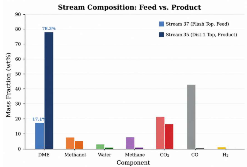
The stream is entirely vapour at 40 °C and 1.52 bar. CO2 dominates on a molar basis at 40.63 mol%, followed by hydrogen (13.54 mol%), methane (12.84 mol%), and CO₂ (12.85 mol%). Together these four light gases account for 79.9 mol% of the feed entering the distillation column. DME is present at only 9.89 mol% (17.1 wt.%), reflecting the fact that at 1.52 bar and 40 °C the vapour pressure of DME is above atmospheric and it remains in the gas phase rather than condensing into the liquid fraction of the flash separator.
The dominance of CO at 2,768.1 kg/h (40.63 mol%) is a direct consequence of the stoichiometric mismatch between the dry reforming product and the requirements of methanol synthesis. The DRM stage produces syngas at H2:CO at 0.93, whereas methanol synthesis requires H2:CO at 2.0–2.5 for optimal conversion. The unconverted CO passes through the methanol reactor, the dehydration reactor, and the flash separator essentially unchanged and accumulates in the stream alongside residual CO2 (1,375.5 kg/h), which represents both unreacted feed CO2 and CO2 produced by the reverse water-gas shift reaction inside the methanol synthesis reactor. The practical consequence for the distillation column is a very high non-condensable gas load relative to the DME content, which demands either a substantial pre-separation step in an optimized design, or acceptance of a large compressor duty to bring all gases to the column pressure. Methanol is present at 473.5 kg/h (6.08 mol%), representing unconverted methanol from the dehydration reactor. A per-pass methanol conversion of 80–85 % in the dehydration step is consistent with the Bercic–Levec kinetics used in the simulation [16], and the methanol that bypasses conversion partitions between the liquid and vapour phases at the flash conditions. That 473.5 kg/h reports to the vapour at 1.52 bar indicates that the flash separator is not cold enough to fully condense the methanol fraction, which is consistent with the vapour pressure of methanol at 40 °C.
Figure 2.
Component mass-fraction distribution in Stream 37 (Flash Top, column feed) and Stream 35 (distillation column 1 Top, column product). DME is enriched from 17.1 wt.% in the feed to 78.3 wt.% in the overhead product? a 4.6-fold mass enrichment. CO2 co-distils with DME.
Figure 2.
Component mass-fraction distribution in Stream 37 (Flash Top, column feed) and Stream 35 (distillation column 1 Top, column product). DME is enriched from 17.1 wt.% in the feed to 78.3 wt.% in the overhead product? a 4.6-fold mass enrichment. CO2 co-distils with DME.
4.2. Distillation Column separation
The stream for the DME separation in the first distillation column (T-101) enters as fully superheated vapor at 40 °C and 1.52 bar. The column overhead product is specified at 10.13 bar and the calculated product state is a fully condensed liquid. The pressure increase from the feed to the column therefore requires the vapor feed to be compressed from 1.52 to 10.13 bar, a pressure ratio of about 6.7:1. The operation of the DME purification column at elevated pressure is consistent with similar process simulation research that have performed DME distillation at pressure conditions between 10–15 bar for the purpose of condensation and downstream product recovery [22,23]. Stage numbers have vary depending on the separation specification and feed composition, with reported designs including 10 stages at 15 bar for CO2-derived DME and 32 stages at 10 bar for a high-purity DME separation [22,23]. The selection of 8 theoretical stages in the present study is not a general rule of the literature but a compact column configuration adapted to the simulated feed and separation. The final number of stages was decided by the stringent ChemCAD calculation and the required DME separation performance.
Table 3 gives the full composition of the overhead top product, which carries 333.5 kg/h of condensed liquid at −39.9 °C and 10.13 bar. DME accounts for 261.0 kg/h (78.3 wt.%), making it the dominant component. CO2 is the second-largest component at 54.0 kg/h (16.2 wt.%), and MeOH contributes 18.2 kg/h (5.5 wt.%). All other species, including water, methane, CO, and H2, are present at trace levels below 0.1 wt.% each.
Table 4.
Full composition of top distillation column from the SCDS simulation. Conditions: T = −39.9 °C, P = 10.0 atm (10.13 bar), vapour fraction = 0.0, total enthalpy = −1,835.4 MJ h⁻¹. Molar flows calculated from ChemCAD mass flows using standard molecular weights.
Table 4.
Full composition of top distillation column from the SCDS simulation. Conditions: T = −39.9 °C, P = 10.0 atm (10.13 bar), vapour fraction = 0.0, total enthalpy = −1,835.4 MJ h⁻¹. Molar flows calculated from ChemCAD mass flows using standard molecular weights.
| Component | Mass flow (kg/h) | Molar flow (kmol/h) | Mole frac. (mol%) |
|---|---|---|---|
| Dimethyl ether (DME) | 261.011 | 5.666 | 75.80 |
| Methanol | 18.246 | 0.569 | 7.62 |
| Water | 0.118 | 0.007 | 0.09 |
| Methane | 0.031 | 0.002 | 0.03 |
| Carbon dioxide | 53.978 | 1.226 | 16.41 |
| Carbon monoxide | 0.107 | 0.004 | 0.05 |
| Hydrogen | 0.002 | <0.001 | 0.01 |
| Total | 333.493 | 7.474 | 100.00 |
The DME concentration of 75.8 mol% in the overhead product is lower than the purity anticipated for fuel-grade DME as stipulated from the current ASTM D7901-23 specification for DME in fuel applications and DME/LPG blending [24]. The main impurities in the simulated overhead are CO2 (16.4 mol%) and MeOH (7.6 mol%), indicating that the first distillation column primarily concentrates the DME but does not fully remove the light CO2 fraction or the heavier methanol fraction. The high CO2 content is thermodynamically feasible since CO2 has good solubility in liquid DME at high pressure [25]. Therefore, the separation of CO2 in DME is one of the harder steps in the purification of DME. At the simulated condenser condition of −39.9 °C and 10.13 bar CO2 is below its critical temperature and should therefore not be described as supercritical. The operating point is rather close to the CO2 vapour-liquid equilibrium region. This phase behavior may contribute to the retention of CO2 in the condensed DME-rich phase and thus limit the achievable DME purity. The simulated methanol (7.6 mol %) also indicates that the methanol is not completely rejected in the first distillation step. Sequential separation has been used in similar CO2 to DME process simulations, which allows the recovery of DME in the first column and methanol and water to be sent to further purification, which demonstrates the importance of downstream separation design for high purity DME [16].
Figure 3.
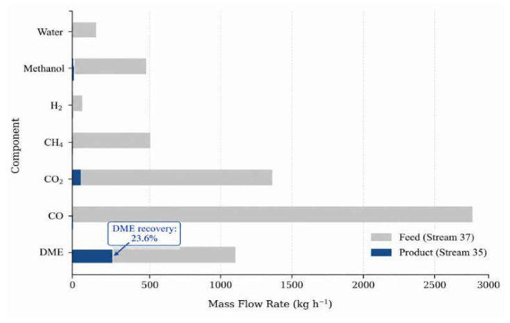
Component mass-flow comparison between distillation feed and product, illustrating the 23.6 % single-pass DME recovery and the large CO and CO2 loads that dominate the feed but are largely rejected to the column bottoms.
Figure 3.
Component mass-flow comparison between distillation feed and product, illustrating the 23.6 % single-pass DME recovery and the large CO and CO2 loads that dominate the feed but are largely rejected to the column bottoms.
The 8 stage column shows a significant concentration of DME with a molar enrichment of 7.67 times from 9.89 mol% in the feed to 75.80 mol% in the overhead product. Additionally, CO, H2 and CH4 were also rejected from the overhead. The calculated rejection of each component was more than 99.9%, indicating the main non-condensable species were effectively rejected from the DME-rich product. The crucial feature of the feed-to-overhead split is the 16.4 mol % CO2 remaining in the condensed product. The operating point at −39.9 °C and 10.13 bar is close to the saturation conditions of pure CO2, the saturation pressure of CO2 at −40 °C is approximately 10.0 bar, while the critical point is approximately 31.0 °C and 73.8 bar. Thus, the CO2-rich component is in a region where small changes in temperature, pressure and composition can have a large effect on phase behavior. The CO2–DME system is characterised by a high affinity between the two components, which makes their separation thermodynamically difficult, a behavior that has been explicitly considered in recent DME purification studies using equation-of-state-based VLE models [25]. Experimental studies of CO2-DME mixtures have also shown that the critical temperature and pressure of the mixture depend strongly on composition and Peng-Robinson calculations predict the measured critical properties with reasonable accuracy [26]. The 16.4 mol% CO2 predicted by the present NRTL calculation is physically consistent with the documented non-ideal phase behavior of the CO2–DME system, although the present comparison should be seen as qualitative rather than as an independent validation of the NRTL parameterisation.
4.3. Mass Balance Closure and Carbon Utilization
A carbon-balance check on the simulation data provides an internal consistency check of the simulation. The feed consists of 1,108.3 kg/h DME, 473.5 kg/h methanol and 1,375.5 kg/h CO₂, which corresponds to a carbon mass flow of about 1,380 kg C/h in organic and CO₂ form. The top product of the distillation contains 261.0 kg/h DME, 18.2 kg/h methanol and 54.0 kg/h CO₂, i.e. a carbon mass flow of about 334 kg C/h. The remainder, some 1,046 kg C/h, is in the column bottoms in methanol, water and trace DME. The carbon balance is within expected rounding tolerance of the stream data. The overall process carbon utilization efficiency (CUE) on a single pass, once through basis is 5.2% as the fraction of feed carbon from CO2 and CH4 appearing as DME carbon in the process product stream. In addition to energy and economic metrics, carbon-utilization metrics are increasingly being used to assess the performance of CO2-to-DME processes [13]. Recycle loop for unconverted carbon containing species, allows for better utilization of carbon by recycling the carbon to the synthesis section instead of rejecting it directly from the process [27].
4.4. Downstream Separation and DME Recovery
The downstream purification section was evaluated from a techno-economic perspective to determine the effectiveness of the separation strategy for recovering DME from the crude reactor effluent. The separation train consists of a primary flash separator, gas compression, refrigerated cooling, a secondary flash separator, and a conventional distillation column. This staged configuration was selected to progressively remove non-condensable gases and concentrate condensable oxygenates before final purification, thereby reducing the separation duty imposed on the distillation column [25]. The primary flash separator removed a significant proportion of condensed water while retaining most of the DME within the vapour phase together with CO, CO2, CH4 and H2. The vapour stream was subsequently compressed to 10 atm and cooled to 10 °C, increasing the dew point of the condensable species and promoting condensation in the second flash separator. Consequently, the bottom product of the second flash separator became a concentrated liquid feed containing predominantly DME, methanol and water, whereas most of the permanent gases remained in the vapour phase [16]. This intermediate concentration step reduced the gas loading entering the distillation column and represents an important process intensification strategy because the column no longer processes the full reactor effluent but only the condensed oxygenate-rich fraction [28].
The distribution of DME across the separation train is summarized in Table 4. The vapour leaving the first flash separator contained 1108.28 kg/h of DME, while the condensed liquid recovered in the second flash separator contained 237.05 kg/h of DME and was subsequently fed to the distillation column. The distillation overhead recovered 261.01 kg/h of DME, corresponding to a column recovery of approximately 90.82% based on the DME entering the column. These results demonstrate that the distillation column itself performs efficiently, with negligible DME losses during purification. However, only 19.1% of the total DME entering the separation section reaches the column because the remaining DME leaves with the vapour stream from the flash separation stage. The overall process recovery is therefore limited by the upstream flash separation rather than by the distillation operation itself. This finding has important implications for process optimization because increasing the number of distillation stages or the reflux ratio would provide little additional benefit unless the recovery of DME during flash condensation is simultaneously improved.
Table 5.
DME distribution through the downstream purification process.
| Separation stage | DME (kg h⁻¹) |
|---|---|
| Flash 1 vapour (after primary flash) | 1108.28 |
| Flash 2 bottom (feed to Distillation 1) | 237.05 |
| Distillation 1 overhead | 261.01 |
From an economic perspective, the principal operating costs of the purification section arise from gas compression, refrigeration and reboiler duty. The refrigeration system is required to cool the compressed vapour sufficiently to condense DME and methanol before distillation, while the distillation column operates with a reboiler duty of approximately 901 MJ/h to achieve the desired separation. Although these utilities increase the operating expenditure, the staged separation strategy reduces the vapour throughput of the column, enabling efficient recovery of DME from a significantly smaller liquid stream. The additional capital investment associated with the compressor, chiller and secondary flash separator is offset by improved column performance and reduced separation complexity. Similar staged condensation and purification strategies have been reported for oxygenated fuel synthesis processes, where upstream condensation reduces downstream separation costs and improves process operability [29,30]. The present process represents a once-through configuration and therefore does not include recycling of the DME-rich vapour leaving the flash separation stage. Future process development should prioritize optimization of the flash separation and recycle configuration rather than further refinement of the distillation system.
5. Conclusions
Steady-state ChemCAD simulation of an integrated three-stage process for dimethyl ether (DME) production from carbon dioxide and methane via dry reforming, methanol synthesis and methanol dehydration has been successfully developed. The simulation combined kinetic reactor models with rigorous thermodynamic calculations to establish a complete process flowsheet comprising reaction, flash separation, compression, refrigeration and distillation. The DRM reactor provided efficient syngas generation, while the methanol synthesis and dehydration reactors achieved methanol conversion of approximately 80% and DME selectivity consistent with values reported for industrial γ-Al2O3 catalysts. The downstream purification section produced a DME-rich overhead product with a purity of 90.82%, demonstrating the suitability of the proposed separation strategy for high-purity DME production. The second flash separator recovered approximately 23.6% of the available DME into the condensed phase, confirming that flash condensation rather than distillation represents the principal opportunity for improving overall DME recovery. The preliminary techno-economic assessment showed that staged flash separation combined with compression, refrigerated cooling, and distillation provides an effective purification strategy by reducing the vapour load entering the distillation column and improving separation efficiency. Although these additional unit operations increase utility requirements, they contribute significantly to product purification and process operability. The developed simulation therefore provides a robust engineering framework for evaluating integrated DME production from greenhouse gas feedstocks and establishes a reliable basis for subsequent process optimization and scale-up studies. The process configuration developed in this study establishes a robust engineering platform for the design and evaluation of integrated DME production systems. The simulation framework can be readily applied to process optimization, heat integration studies, scale-up analysis, supporting the continued development of sustainable DME production from carbon dioxide and methane.
Author Contributions
Conceptualization, M.M., T.S., I.K., and R.M.; methodology, M.M., T.S., I.K., and R.M.; software, M.M., T.S., I.K., and R.M.; formal analysis, M.M., T.S., I.K., and R.M investigation, M.M., T.S., I.K., and R.M.; data curation, M.M., T.S., I.K., and R.M.; writing—original draft preparation, M.M., I.K., and R.M.; writing—review and editing, M.M., T.S., I.K., and R.M.; supervision, T.S.; project administration, T.S. All authors have read and agreed to the published version of the manuscript.
Funding
This study did not receive any funding.
Data Availability Statement
The data presented in this study are available from the corresponding author upon reasonable request.
Acknowledgements
During the preparation of this manuscript, the author(s) used ChatGPT 3, OpenAI, for language editing and structural organization of paragraphs. The authors have reviewed and edited the output and take full responsibility for the content of this publication.
Conflicts of Interest
The authors declare no conflict of interest.
References
- Yusuf, N.; Almomani, F.; Qiblawey, H. Catalytic CO2 Conversion to C1 Value-Added Products: Review on Latest Catalytic and Process Developments. Fuel 2023, 345, 128178. [Google Scholar] [CrossRef]
- Peinado, C.; Liuzzi, D.; Sluijter, S.N.; Skorikova, G.; Boon, J.; Guffanti, S.; Groppi, G.; Rojas, S. Review and Perspective: Next Generation DME Synthesis Technologies for the Energy Transition. Chem. Eng. J. 2024, 479, 147494. [Google Scholar] [CrossRef]
- Hilfinger, F.; Kubas, D.; Krossing, I. Does Direct Dimethyl Ether Synthesis from Carbon Dioxide and Hydrogen Yield More Valuable Products than the Equivalent Methanol Production? A Review on Recent Work. Chem. Ing. Tech. 2024, 96, 1060–1070. [Google Scholar] [CrossRef]
- Stöber, R.; Seidl, F.; Hoffmann, E.; Wasserscheid, P.; Schühle, P. A Highly Durable Catalyst System for Hydrogen Production from Dimethyl Ether. Sustain. Energy Fuels 2024, 8, 1740–1749. [Google Scholar] [CrossRef]
- Ebrahimian, S.; Bhattacharya, S. Direct CO2 Hydrogenation over Bifunctional Catalysts to Produce Dimethyl Ether—A Review. Energies 2024, 17, 3701. [Google Scholar] [CrossRef]
- Chmielarz, L. Dehydration of Methanol to Dimethyl Ether—Current State and Perspectives. Catalysts 2024, 14, 308. [Google Scholar] [CrossRef]
- Cabrera-Gallardo, D.; Quintero-Quintana, M.C.; Baena-Moreno, F.M.; Rodríguez-Galán, M.; Vidal-Barrero, F. A Narrative Review of Dimethyl Ether Production Technologies with a Focus on Landfill Biogas Potential as Feedstock. Methane 2026, 5, 16. [Google Scholar] [CrossRef]
- Sanna, A.; Openshaw, D.; Oghotomo, P.; Bagnato, G. Steam Reforming of Methane: State of the Art and Novel Technologies. React. Chem. Eng. 2025, 10, 1963–1977. [Google Scholar] [CrossRef]
- Mosaad Awad, M.; Kotob, E.; Ahmed Taialla, O.; Hussain, I.; Ganiyu, S.A.; Alhooshani, K. Recent Developments and Current Trends on Catalytic Dry Reforming of Methane: Hydrogen Production, Thermodynamics Analysis, Techno Feasibility, and Machine Learning. Energy Convers. Manag. 2024, 304, 118252. [Google Scholar] [CrossRef]
- Weber, J.L.; Mejía, C.H.; de Jong, K.P.; de Jongh, P.E. Recent Advances in Bifunctional Synthesis Gas Conversion to Chemicals and Fuels with a Comparison to Monofunctional Processes. Catal. Sci. Technol. 2024, 14, 4799–4842. [Google Scholar] [CrossRef] [PubMed]
- Bhaskaran, A.; Singh, S.A.; Reddy, B.M.; Roy, S. Integrated CO2 Capture and Dry Reforming of CH4 to Syngas: A Review. Langmuir 2024, 40, 14766–14778. [Google Scholar] [CrossRef] [PubMed]
- E-Moghaddam, M.; Dahmen, N.; Santo, U.; Sauer, J. Gasoline Synthesis from Biomass-Derived Syngas Comparing Different Methanol and Dimethyl Ether Pathways by Process Simulation, Based on the Bioliq Process. Energy Fuels 2024, 38, 4229–4243. [Google Scholar] [CrossRef]
- Dieterich, V.; Neumann, K.; Niederdränk, A.; Spliethoff, H.; Fendt, S. Techno-Economic Assessment of Renewable Dimethyl Ether Production Pathways from Hydrogen and Carbon Dioxide in the Context of Power-to-X. Energy 2024, 301, 131688. [Google Scholar] [CrossRef]
- Fedeli, M.; Negri, F.; Bornazzini, A.; Montastruc, L.; Manenti, F.; Kiss, A.A. Process Design and Downstream Optimization of the Direct Synthesis Route for Cleaner Production of Dimethyl Ether from Biogas. J. Clean. Prod. 2024, 443, 141060. [Google Scholar] [CrossRef]
- Rodrigues Niquini, G.; Lacerda de Oliveira Campos, B.; Herrera Delgado, K.; Pitter, S.; Sauer, J. Experimental Study and Comprehensive Kinetic Modeling of the Direct Dimethyl Ether Synthesis on Cu/ZnO/ZrO2 and H-FER-20. Chem. Eng. J. 2024, 480, 147968. [Google Scholar] [CrossRef]
- Essam, M.; Gad, F.; Abouseada, N.; Soliman, M.A.; Aboelela, D. Process Simulation for Converting CO2 Emissions from the Cement Industry to Dimethyl Ether. Arab J. Sci. Eng. 2025, 50, 4065–4076. [Google Scholar] [CrossRef]
- Zhu, H.; Chen, H.; Zhang, M.; Liang, C.; Duan, L. Recent Advances in Promoting Dry Reforming of Methane Using Nickel-Based Catalysts. Catal. Sci. Technol. 2024, 14, 1712–1729. [Google Scholar] [CrossRef]
- Song, M.; Liu, Q.; Zhao, F.; Liu, S.; Lei, Z. Experimental and Simulation Studies on the Simultaneous Removal of Methanol and Water from Dimethyl Ether Crude Gas by Choline-Based Deep Eutectic Solvents. Fuel 2024, 371, 131882. [Google Scholar] [CrossRef]
- Moioli, E.; Schildhauer, T. A System for the Combined Carbon Capture and Utilization to Produce Renewable Methanol from Biogas. Chem. Ing. Tech. 2024, 96, 826–839. [Google Scholar] [CrossRef]
- Zhang, D.; Zeng, S.; Li, Z.; Yang, M.; Feng, X. Simulation-Assisted Design of a Distillation Train with Simultaneous Column and Sequence Optimization. Comput. Chem. Eng. 2022, 164, 107907. [Google Scholar] [CrossRef]
- Li, Q.; Finn, A.J.; Doyle, S.J.; Smith, R.; Kiss, A.A. Synthesis and Optimization of Energy Integrated Advanced Distillation Sequences. Sep. Purif. Technol. 2023, 315, 123717. [Google Scholar] [CrossRef]
- Alotaibi, M.M.; Alturki, A.A. Optimizing Renewable Energy Integration for Sustainable Fuel Production: A Techno-Economic Assessment of Dimethyl Ether Synthesis via a Hybrid Microgrid-Hydrogen System. Fuels 2024, 5, 176–209. [Google Scholar] [CrossRef]
- Perdana, M.M.G.; Andika, R.; Susanto, B.H.; Steven, S.; Nishiyama, N.; Sophiana, I.C. Transforming CO2 Emissions into Fuel: An Energy Analysis of Dimethyl Ether Production Pathways. Results Eng. 2025, 25, 104330. [Google Scholar] [CrossRef]
- ASTM International Standard Specification for Dimethyl Ether for Fuel Purposes. Available online: https://store.astm.org/d7901-23.html (accessed on 23 September 2026).
- Dikić, V.; Zubeir, L.; Sarić, M.; Boon, J. Stripping Enhanced Distillation—A Novel Application in Renewable CO2 to Dimethyl Ether Production and Purification. Separations 2023, 10, 403. [Google Scholar] [CrossRef]
- Shu, G.; Hu, S.; Wang, X.; Chen, Y.; Tian, H. Measurement of Key Critical Parameters for Binary Mixture of Carbon Dioxide (CO2) + Dimethyl Ether (DME) and Modification of the CO2 + Hydrocarbon (HC) Prediction Model. J. Supercrit. Fluids 2025, 224, 106668. [Google Scholar] [CrossRef]
- Wang, Y.; Babaei, H. Integrated Direct Dimethyl Ether Synthesis Process Based on Internal Cycle of CO2: Technical Economy and Multi-Criteria Evaluation for Carbon Capture, Utilization, and Storage. AIP Adv. 2026, 16, 065212. [Google Scholar] [CrossRef]
- Nakayama, Y.; Kaneko, H. Robust Design of a Dimethyl Ether Production Process Using Process Simulation and Robust Bayesian Optimization. ACS Omega 2023, 8, 29161–29168. [Google Scholar] [CrossRef] [PubMed]
- D’Ambrosio, A.; de Oliveira Campos, B.L.; Sauer, J.; Piemonte, V. Multi-Stage Direct Synthesis of Dimethyl Ether: Integrated Thermodynamic, Economic and Environmental Assessment for Process Intensification. Chem. Eng. J. 2026, 542, 177914. [Google Scholar] [CrossRef]
- Mangalindan, J.R.; Mahnaz, F.; Vito, J.; Suphavilai, N.; Shetty, M. Tandem Cu/ZnO/ZrO2-SAPO-34 System for Dimethyl Ether Synthesis from CO2 and H2: Catalyst Optimization, Techno-Economic, and Carbon-Footprint Analyses. ACS Eng. Au 2025, 5, 267–283. [Google Scholar] [CrossRef] [PubMed]
Table 1.
Thermodynamic constraints and assumptions.
| Parameter | Specification |
|---|---|
| Simulation mode | Steady state |
| Thermodynamic model | NRTL |
| K-value method | SRK |
| Enthalpy method | SRK (Latent heat) |
| Reaction models | Kinetic PFR and equilibrium DRM |
| Heat losses | Neglected |
| Catalyst deactivation | Neglected |
| Pressure drop | Unit operation specific |
Table 2.
Reactor configuration for DRM, MeOH synthesis and DME formulation.
| Reactor | Type | Temperature (°C) | Pressure (bar) |
|---|---|---|---|
| Reactor 1 (DRM) | Kinetic PFR | 850–950 | 1.0 |
| Reactor 2 (MeOH) | Kinetic PFR | 227 (500 K) | 44 |
| Reactor 3 (DME) | Kinetic PFR | 218 → 72 | 29.4 |
Disclaimer/Publisher’s Note: The statements, opinions and data contained in all publications are solely those of the individual author(s) and contributor(s) and not of MDPI and/or the editor(s). MDPI and/or the editor(s) disclaim responsibility for any injury to people or property resulting from any ideas, methods, instructions or products referred to in the content. |
© 2026 by the authors. Licensee MDPI, Basel, Switzerland. This article is an open access article distributed under the terms and conditions of the Creative Commons Attribution (CC BY) license.
Copyright: This open access article is published under a Creative Commons CC BY 4.0 license, which permit the free download, distribution, and reuse, provided that the author and preprint are cited in any reuse.