

Submitted:
19 September 2026
Posted:
20 September 2026
You are already at the latest version
Abstract
Conventional catenary mooring systems for floating offshore wind turbines (FOWTs) face significant challenges related to high installed cost, large seabed footprint, and supply chain constraints. To address these challenges, this paper proposes a novel length-varying tension-fixed (LVTF) mooring concept characterized by a compact seabed footprint. Theoretical formulations are developed, and parametric study results are presented on the fundamental station-keeping characteristics of a single-anchor LVTF mooring concept for a 15 MW semi-submersible FOWT. Preliminary design of a multi-anchor passive LVTF mooring system in 100 m water depth with a mooring anchor radius of 70 m is performed for a 16 MW multi-column Spar-type FOWT for potential deployment in the South China Sea. A wave basin model test campaign is conducted to validate the design of the passive LVTF mooring system for the Spar-type FOWT under extreme typhoon conditions. The model test results, including platform global motions and mooring line tensions, are compared with those of the conventional catenary mooring design. It is found that the small-footprint passive LVTF mooring system can provide adequate station-keeping forces for the 16 MW Spar-type FOWT. A preliminary cost assessment indicates a potential installed-cost reduction of approximately 67% in comparison with the conventional catenary mooring design.
Keywords:
floating wind turbine
; multi-column spar
; mooring system
; length-varying tension-fixed
; model test
1. Introduction
There is a growing imperative to deploy cost-effective floating offshore wind turbines (FOWT) to harness the immense wind resources in deep waters, where conventional bottom-fixed foundations are considered economically unviable. This potential is underscored by projections, such as DNV's Energy Transition Outlook 2023, which forecasts floating offshore wind capacity could reach 300 GW by 2050 [1]. However, the total installed capacity of FOWTs remains modest at roughly 230 MW, dwarfed by the over 68,000 MW for fixed-bottom foundations at the end of 2023 per NREL [2]. The main challenge is that current FOWT designs incur a significant cost penalty, making it less viable for commercial projects. Achieving floating wind cost-effectiveness requires innovations across all systems, particularly in floating platforms and mooring systems, which represent the largest portions of the total cost.
The past decade has seen significant technological progress in floating offshore wind technologies. Substantial innovations have been seen in floating platform designs [3,4,5], and wind turbines with dramatic increases in capacity from 5 MW [6] to 22 MW [7] and beyond. In contrast, the evolution of mooring system design has been incremental. Prevailing mooring solutions for FOWTs remain adaptations of offshore oil and gas archetypes, namely, catenary, taut-leg, and tension leg systems [8,9,10]. This constitutes a critical impediment to achieving the cost reductions and scalability essential for commercial development of deep-water offshore wind energy.
While the existing mooring concepts are supported by proven design tools, modeling methods, and industry standards derived from extensive offshore oil and gas experience, they remain costly, complex, and highly customized. Consequently, they are ill-suited for large-scale, standardized deployments demanded by the offshore wind industry. One of the challenges is the extensive seabed footprint for catenary and taut-leg/semi-taut mooring systems. This spatial requirement not only poses potential environmental risks but also significantly reduces the power generation density of a wind farm. According to NREL [11], when compared to a compact/vertical mooring configuration like a tension leg platform, a large mooring footprint could diminish a commercial farm's electricity generating capacity by 20% to 30%. Although the tension leg mooring offers a compact seabed footprint, its high installed cost compared to catenary or taut-leg systems renders it economically unviable for utility-scale deployment. Furthermore, in shallow water depths less than 100 meters, technical challenges for all three existing mooring concepts intensify significantly [12,13], leading to further cost escalations.
In response to these challenges, multiple strategies have been researched to reduce cost and minimize environmental impact. One direction involves employing lightweight synthetic materials, such as nylon ropes, to lower material costs [14,15]. Other directions include developing hybrid catenary mooring concepts with the integration of clump weights or buoyancy modules [16,17], and load-reduction devices to mitigate peak dynamic tensions [18,19]. Significant effort has also been dedicated to optimizing conventional designs through frequency domain analysis [20], integrating deep neural networks [21], and surrogate modeling [22]. While these approaches offer incremental improvements, they largely represent optimizations of existing paradigms rather than a fundamental shift in mooring design for the specific needs of floating wind. For floating wind farm arrays with multiple floating wind turbines, system-level innovations have been proposed to enhance economy-of-scale in mooring systems. These include the shared anchor concepts by multiple floating wind turbines [23,24,25,26] and the shared mooring line concepts between the floating platforms [27,28].
Recognizing that modifications or optimizations of existing mooring concepts are insufficient to fully address the mooring challenges for floating wind turbines, a new Length-Varying Tension-Fixed (LVTF) mooring theory was previously proposed [29]. A novel LVTF subsea single point mooring concept was subsequently investigated for a semi-submersible FOWT in shallow water [30] using numerical simulations with an idealized LVTF mechanism. Building upon this foundation, this study presents several key contributions: (1) development of mathematical models for the LVTF mooring concept; (2) in-depth analytical study of the LVTF mooring concept; (3) proposal of a multi-anchor gravity-based passive LVTF mooring design for a multi-column Spar-type FOWT; and (4) experimental investigation to validate the LVTF mooring concept through wave basin model testing with the multi-column Spar-type FOWT. The results of the theoretical analyses and model tests will be presented.
2. Mooring Theories and Concepts
2.1. Conventional Mooring Theory of Length-Fixed Tension-Varying
The primary function of a mooring system is station-keeping, i.e., to restrain a floating structure within an acceptable operational radius by providing a restoring force in response to horizontal offsets from its equilibrium position. The relationship between the floating structure's offset (ΔX) and the resulting restoring force (R) is governed by two fundamental variables: mooring line length (L) and tension (T) and serves as a key performance indicator for any mooring system.
The default theory for conventional mooring system design is the Length-Fixed Tension-Varying (LFTV) paradigm. This means the physical length of the mooring line between the mooring fairlead on the floater and the anchor on the seabed is fixed; consequently, the line tension must vary as the floating body moves away from its neutral position. This holds true regardless of the mooring line's configuration (catenary, taut-leg, etc.) or material properties. A critical consequence of this design paradigm is the potential for extreme tension fluctuations. For example, in shallow waters less than 100 m, the line tension in a conventional catenary mooring system can increase exponentially by over 5 to 10 times of the pre-tension [12]. This occurs as the floater's offset increases and the mooring line is tightened, approaching its full physical length under the extreme environmental loading. Therefore, this conventional LFTV mooring design paradigm is recognized as one important contributor to the technical and economic challenges for station-keeping system, including high costs and complex engineering, hindering the commercial-scale deployment of floating wind turbines. To date, it has formed the foundational, yet limiting, framework for all conventional mooring system designs.
2.2. Existing Mooring Concepts
The three main existing mooring concepts, namely catenary, taut-leg, and tension leg mooring systems, are shown schematically in Figure 1 below.
Presently, the catenary mooring system is by far the most widely used station-keeping concept in the offshore industry. The catenary shape/configuration of the mooring line provides the needed compliant offset range and horizontal restraining/restoring force through the weight of the steel chain and/or wire suspended in the water as the floater has a horizontal offset from its equilibrium position. Low-cost drag anchors and steel chains and/or wires are typically used for the catenary mooring system. There is generally a heavy segment of the mooring line consisting of steel chains on the seabed. This keeps the anchor uplift force to zero and allows the use of low-cost drag anchors. The main shortcomings of catenary mooring are: 1) large footprint on the seabed, 2) too heavy for deep waters, 3) not very effective for station-keeping in shallow waters as the water column is too shallow for the mooring line to develop an effective catenary shape to restrain the floater from large offset. For FOWT in shallow waters, say 50 m, the maximum horizontal offset or surge/sway could exceed 15 m, or 30% of the water depth.
The taut leg mooring concept in general relies on axial elongation of the mooring line to provide the offset flexibility for the floater. Since the mooring line stiffness is a function of both the mooring line material and the mooring length, the taut leg mooring is mostly suitable for deep waters. Note that a semi-taut mooring system is generally considered to belong to the taut leg mooring category. It has a mooring line shape of a taut catenary shape with high pre-tension. Light weight synthetic fiber ropes, such as polyester ropes with much smaller stiffness than steel chain/wire, are often used for deep-water oil and gas floating production platforms. The problems with the taut leg mooring concept include mooring line material selection, complicated nonlinear behavior of the synthetic mooring ropes under highly dynamic tension loading, long term fatigue, inspection and maintenance, high uplift force on the anchor. For shallow water station-keeping of FOWTs, new mooring rope materials or construction methods of synthetic ropes have been introduced to provide higher elasticity to meet the offset requirements. But presently, there is a lack of experience in using such new materials for long-term mooring installations. It is important to develop qualification testing procedures and accumulate quality test data for design to support the long-term use of the new mooring line materials.
The tension leg mooring concept is typically associated with the tension leg platform (TLP) which relies on the tension of the vertical tendons for platform stability and station-keeping. The tendons are typically made of steel pipes and highly tensioned for oil and gas TLPs. The tendons are designed to restrict the vertical heave motion of the TLP but allow horizontal offset. The horizontal restoring force of the tension leg system is the sum of the horizontal components of the tension forces in the tension legs. The main advantage of tension leg mooring over catenary and taut leg mooring is that it has a small footprint. The shortcomings include dynamic tension highly coupled with the TLP heave motion, high anchor uplift force, tendon fatigue and installation issues, which in general result in prohibitively high cost for the tendon and anchor systems.
2.3. New Mooring Theory of Length-Varying Tension-Fixed
To overcome the inherent limitations of the conventional mooring designs with the Length-Fixed Tension-Varying paradigm, a new mooring theory of Length-Varying Tension-Fixed (LVTF) was proposed [29,30]. It inverts the traditional mooring design paradigm by switching the physics of the mooring line length and tension, i.e., the physical length of the mooring line is allowed to vary, while the mooring line tension is kept to a constant predetermined value despite changes of the horizontal offset of the floating structure.
A schematic of the LVTF mooring concept is illustrated in Figure 2, an idealized 2-line 1-anchor mooring system.
Theoretical modeling of the new concept LVTF mooring system has been conducted to quantify the mooring system’s restoring force as a function of the horizontal offset of the floating structure. The simplest mathematical model to describe the LVTF concept is an idealized 2-dimensional mooring system with 2 mooring lines and 1 anchor, and constrains the floating structure’s motion to 1 degree of freedom (horizontal offset or surge), herein referred to as the 2-2-1-1 model, as shown in Figure 2. Assuming both the two mooring lines have zero weight and zero axial stiffness, and a pre-tension of T, the floating structure will be at the zero offset initial position without external forces as shown in Figure 2a. As the floating structure moves rightward under external environmental (wind and wave) forces, the effective length (fairlead-to-anchor distance) of the right line (Line 1) will increase while that of the left line (Line 2) will decrease, i.e., length-varying. In the meantime, the mooring line tensions, T1 and T2, will remain unchanged equal to the pre-tension T, i.e., tension-fixed, since the axial stiffness of the mooring lines are assumed to be zero. At the offset position as shown in Figure 2b, a new equilibrium will be established. The mooring line angle α1 for the right line (Line 1) with respect to the waterline will become smaller and α2 for the left line (Line 2) will become larger. This will result in a mooring system restoring force R, which is the resultant force of the horizontal component forces of the two mooring lines, equal to the sum of the external forces. For simplicity, the external forces are assumed to be static forces.
For the 2-2-1-1 LVTF mooring system shown in Figure 2, the restoring force R can be expressed below in Eq. (1):
R = T1cosα1− T2cosα2 (1)
where, α1 and α2 are the mooring line angles, and T1 and T2 are the mooring line tensions for Line 1 and Line 2, respectively.
Since the mooring line tension T is fixed to a constant value, the restoring force ratio Rr, defined as the restoring force R divided by T can be used as the main characteristic for the LVTF mooring system as given in Eq. (2):
where, X1 and X2 are horizontal distances from the mooring attachment point (MAP) 1 and MAP 2 to the anchors, and L1 and L2 are the mooring line lengths of Line 1 and Line 2, respectively.
For a given floating body and water depth, h, the MAP vertical distance Z0 to seabed and the initial distance X0 for MAP 1 and 2 can be determined assuming symmetry. Therefore, for the floating body with the 2-line LVTF mooring system, the non-dimensional restoring force ratio Rr can be derived as a function of the offset ΔX with below equations:
X1 = X0+ ∆X (3)
X2 = X0− ∆X (4)
(5)
(6)
Finally, the mooring system restoring force R can be expressed as:
The mooring line tension vs. offset curve of the 2-2-1-1 LVTF mooring system is calculated using Eq. (8) and compared with a typical catenary mooring system in 70 m water using all steel chains. The mooring line tension vs. offset curves of the two mooring systems exhibit quite different behavior. As can be seen in Figure 3, the line tension of the catenary mooring system starts to increase exponentially with the increase of the offset as the floater moves into the high-tension region with the offset greater than 14 m or 20% of the water depth. In contrast, the LVTF mooring system line tension remains constant (set at 5000 kN) as the offset increases from 0 to 20 m. Specifically, at the maximum offset of 20 m or 28.5% of the water depth, the maximum mooring line tension of the catenary mooring system is about 30000 kN, or six times the 5000 kN value for the LVTF mooring system, as shown below.
To gain further insights of the restoring force behavior of the LVTF system, the mooring restoring force is plotted against the offset for three water depths, 600 m, 800 m, and 1000 m, with X0 of 50 m and a constant line tension of 5000 kN. The results are shown in Figure 4 below.
As can be seen, the mooring restoring force of the LVTF system increases practically linearly for the plotted offset range as the offset increases while the line tension remains constant at 5000 kN. The slope of the restoring force curve becomes shallower as the water depth increases from 600 m to 1000 m indicating the LVTF mooring system is getting softer for the same pre-tension or constant tension. The mooring restoring force against the non-dimensional offset to water depth ratio is plotted in Figure 5 below.
It can be seen that the slopes of the mooring restoring force curves are practically the same when plotted against the offset to water depth ratio. This indicates that the mooring restoring force behavior is more or less a linear function of the offset to water depth ratio which can be used as a key parameter for standardized design of the LVTF system over a wide range of water depth and pretension values.
In addition to the simplified 2-2-1-1 model, a general three-dimensional mathematical model of an idealized 3-line 1-anchor LVTF system, referred to as the 3-3-1-3 model, i.e., 3-dimensional, 3 mooring lines, 1 anchor and 3 degrees of freedom motions (surge, sway, and heave), is also developed to obtain the mooring restoring force as a function of the directional offsets. Since this is a three-dimensional problem, a fixed Cartesian coordinate system Oxyz is defined with the origin at the center of the water plane of the floating body, the x-axis and y-axis along the still water surface and the z-axis pointing vertically upwards. The coordinates of the anchor Point Q are (0, 0,−h). The 3-3-1-3 model of the LVTF mooring system is illustrated in Figure 6 below.
There is only one anchor in the above mooring system, which is located on the seabed in the center shared by three mooring lines, Line 1, Line 2 and Line 3, and the water depth is h. At the initial position, assuming symmetry, the lengths of the three mooring lines all equal to L and tensions equal to T, and the floating body is in equilibrium. As the floating body moves under external forces, the length L1 of Line 1, the length L2 of Line 2 and the length L3 of Line 3 vary while the line tension T1, T2 and T3 remain constant. Line 1, Line 2, and Line 3 have mooring angle α1, α2 and α3 with respect to the x-axis, mooring angle β1, β2 and β3 with respect to the y-axis, and mooring angle γ1, γ2 and γ3 with respect to the z-axis. Point A, B and C are three MAPs on the floating body, and initial coordinates of them in the Cartesian coordinate system Oxyz are (X1, Y1,Z1), (X2, Y2,Z2) and (X3, Y3,Z3).
The horizontal restoring force acting on the floating body along the x-axis and y-axis can be expressed as:
Specifically, for a constant T, the horizontal restoring force Rx and Ry can be derived and expressed as:
where i = 1, 2, 3, and the surge, sway, and heave motions to water depth ratio of the floating body are denoted by , and , respectively.
For deep water, the dimensionless heave motion to water depth ratio , thus Equations (11) and (12) can be simplified to Equations (13) and (14) for practical purposes as follows:
These equations can be used to calculate the mooring restoring forces for the 3-3-1-3 LVTF system design.
The theoretical formulations above are used in a case study with a semi-submersible floating wind turbine, the 15 MW VolturnUS-S semi-submersible platform [31], in quasi-static conditions. Main dimensions of the VolturnUS-S semi-submersible platform are given in Table 1 below.
The configuration of a 3-line 1-anchor LVTF mooring system for the 15 MW VolturnUS-S semi-submersible FOWT in 200 m and 70 m water depth is illustrated in Figure 7 below.
The horizontal restoring force curves of the above LVTF system are plotted with 3000, 5000 and 7000 kN pretensions, and compared with a typical catenary mooring system in 200 m, and 70 m water depth as shown below in Figure 8.
It can be seen that the catenary system exhibits pronounced nonlinear characteristics for both water depths. When the offset reaches approximately 0.2 - 0.25h, the restoring force increases exponentially. The nonlinear behavior is seen worse in shallow water (70 m) than in deep water (200 m). In contrast, the restoring force of the LVTF mooring system maintains a nearly linear increase throughout the entire offset range for both water depths.
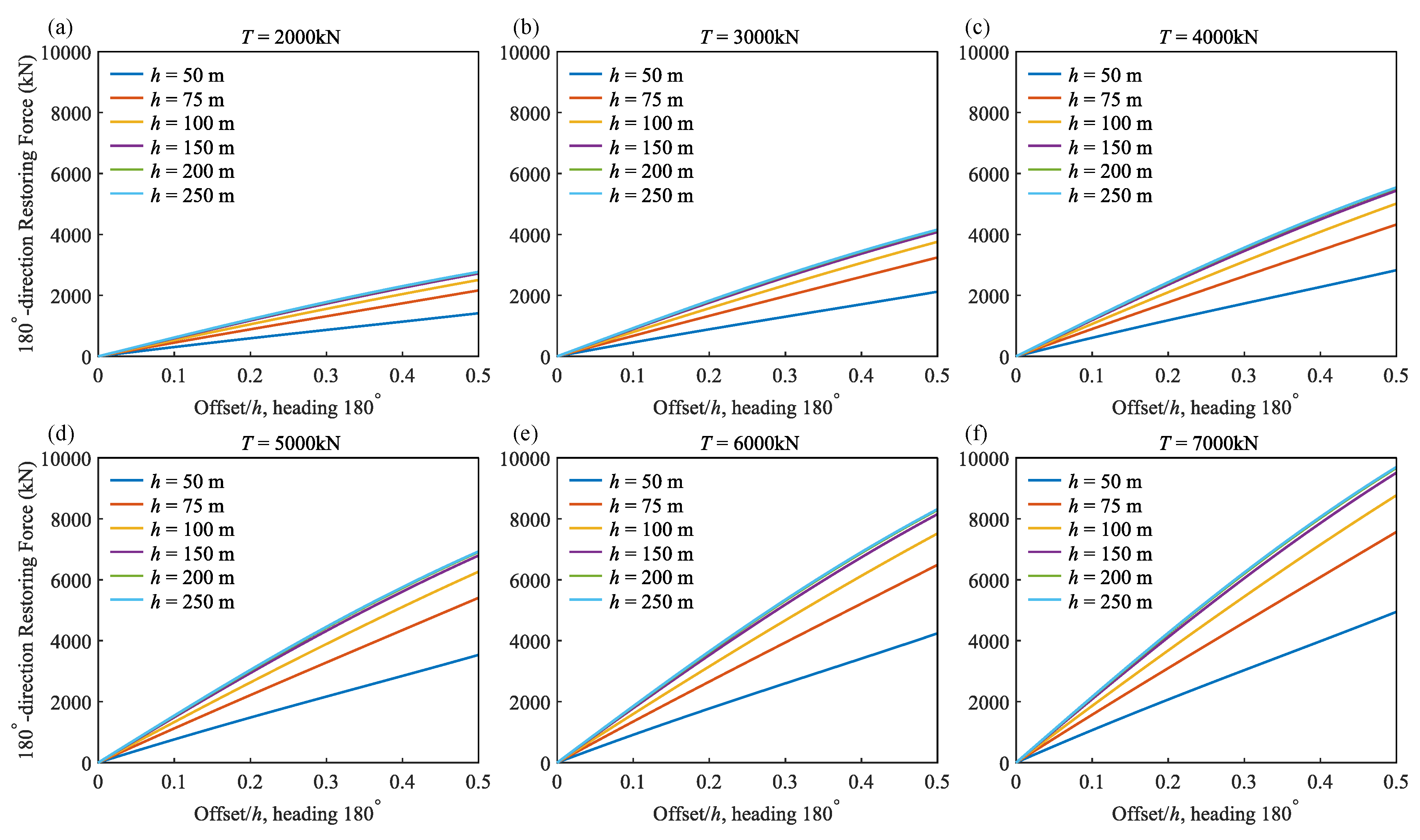
To comprehensively evaluate the performance of the 3-line 1-anchor LVTF mooring system for the 15 MW semi-submersible FOWT, a systematic parameter sensitivity study is conducted. Based on the 3-3-1-3 theoretical model, the variation of the mooring system restoring force with respect to the pre-tension T and water depth h was calculated for 2 headings, 0° (in-line) and 180° (between lines), for a dimensionless horizontal offset range of 0 to 0.5h. The results are presented below. By comparing and analyzing the results, the mooring restoring force characteristics can be identified.
Based on the above analytical results, the following observations are made for the LVTF mooring system:
(1) Stable linear restoring force gradient
As observed in all figures, the horizontal restoring force of the system increases uniformly throughout the entire offset process (0–0.5h), exhibiting a clear linear pattern. This linear characteristic indicates that the LVTF system stiffness remains highly stable, effectively overcoming the common drawbacks of traditional catenary mooring systems, which are prone to highly nonlinear behavior at large offsets.
(2) Linear dominance of pre-tension over the restoring force gradient
The results demonstrate that the horizontal stiffness of the system (i.e., the slope of the restoring force-offset curve) exhibits extreme sensitivity and absolute dependence on the pre-tension T. Regardless of the water depth, as the pre-tension increases arithmetically (in increments of 1000 kN), the peak horizontal restoring forces in the 0° and 180° directions increase significantly in equal proportion. The high positive correlation between the restoring force curve slope and pre-tension T confirms that the pre-tension parameter is the primary factor defining the performance of the LVTF system.
(3) Convergence towards isotropy with increasing water depth
A comparison of the data across different headings reveals a significant geometric phenomenon. In shallow water conditions (e.g., h = 50 m), the restoring forces exhibit a degree of asymmetry across different directions: the restoring force in the 0° direction is higher (just above 6000 kN at offset 0.5h), as shown in Figure 9(a), than the 180° direction (over 5656 kN at offset 0.5h) as shown in Figure 10(a). This asymmetry originates from the geometric layout of the three-point mooring pattern—offsetting towards 0° heading (in-line) results in direct in-line tensioning of one line with relatively greater horizontal MAP offset, whereas offsetting towards 180° (between lines) engages the simultaneous but indirect tensioning of two lines with relatively smaller horizontal MAP offset. However, as the water depth h increases, this asymmetry is significantly attenuated. When the water depth reaches 250 m, the restoring forces for both headings under the same tension of T = 7000 kN converge to approximately 9600 kN, as shown in Figure 9(f) and Figure 10(f). This indicates that in deep water, the pre-tensioned LVTF mooring system spontaneously evolves towards reduced directional dependence. Consequently, the single anchor LVTF mooring system can provide consistent station-keeping performance less sensitive to environmental loading directions under the investigated conditions.
Figure 9.
Effect of constant tension on restoring force under various water depths, 0° heading (in-line).
Figure 9.
Effect of constant tension on restoring force under various water depths, 0° heading (in-line).
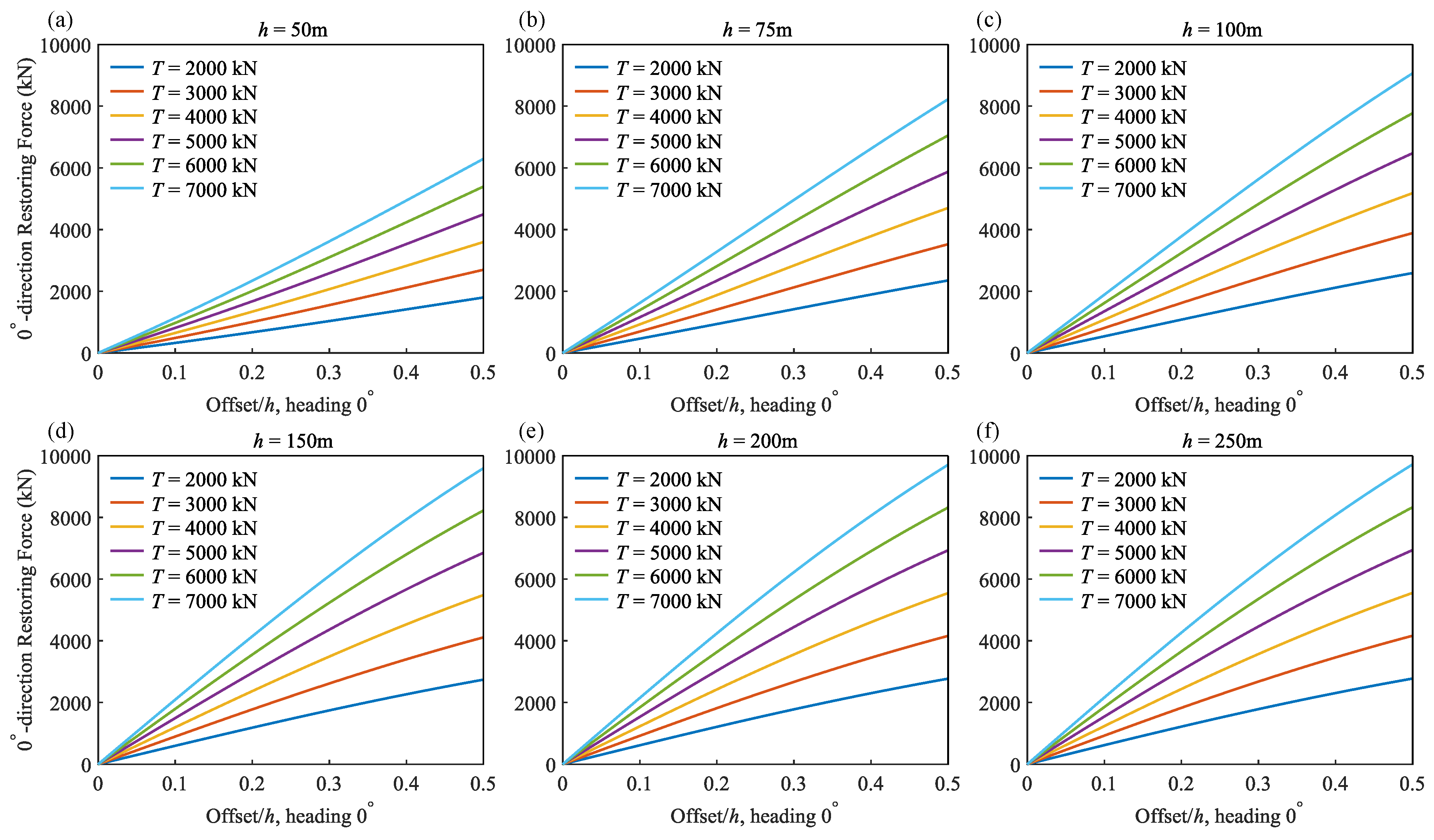
Figure 10.
Effect of constant tension on restoring force under various water depths, 180° heading (between lines).
Figure 10.
Effect of constant tension on restoring force under various water depths, 180° heading (between lines).
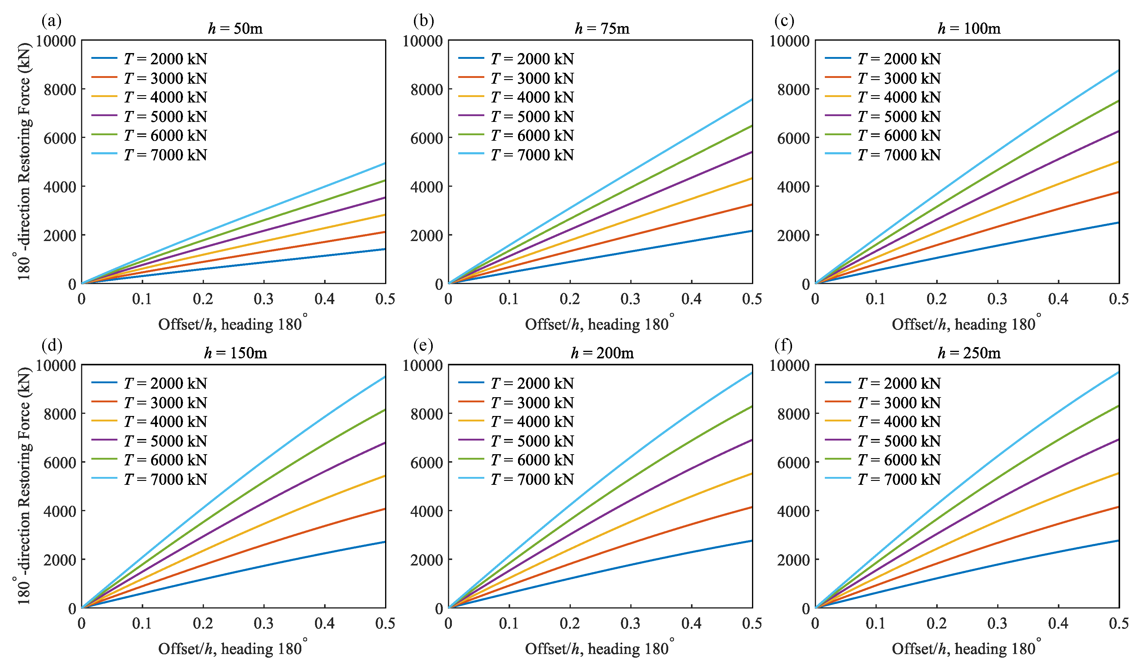
Figure 11.
Effect of water depth on restoring force under various constant tensions, 0° heading (in-line).
Figure 11.
Effect of water depth on restoring force under various constant tensions, 0° heading (in-line).
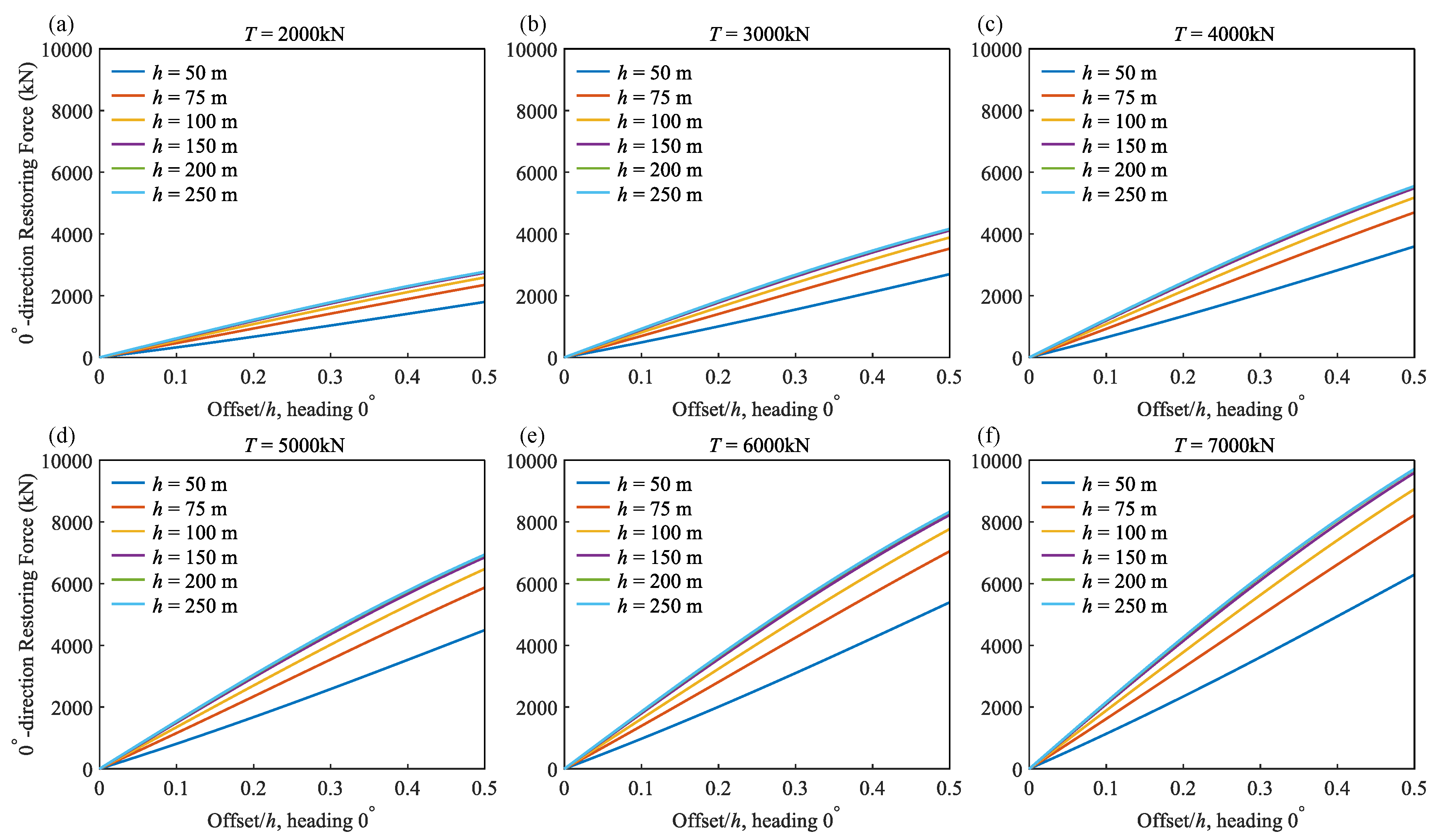
Figure 12.
Effect of water depth on restoring force under various constant tensions, 180° heading (between lines).
Figure 12.
Effect of water depth on restoring force under various constant tensions, 180° heading (between lines).
2.4. Passive LVTF Mooring Concept
There are various ways to achieve LVTF station-keeping functionality. For example, one way is using an active-controlled constant tension winch system on the floating platform. Another way is using a hybrid active-passive tensioning system similar to the riser tensioners commonly used for deep-water oil and gas drilling risers. However, both these active and hybrid active-passive systems will be too costly for floating wind. In this study, a low-cost gravity-based passive LVTF mooring concept is introduced, and is illustrated in Figure 13 below using the simplified 2-2-1-1 model.
The idea is to use a fairlead/pulley subsystem with a flexible counterweight, consisting of a fairlead pulley wheel and a hanging counterweight, here referred to as the pendent gravity unit (PGU). It provides the constant tension in the mooring line through the pulley wheel, thus also called the constant tension unit (CTU). This concept is an application of the classic pulley principle for station-keeping of a floating structure in accordance with the first principles of physics. One example application of hanging a passive large counterweight for a floating wind turbine is the Tetra Spar [32]. Assuming no friction in the pulley wheel, this pulley-PGU subsystem will keep the mooring line tension constant, equal to the weight of the PGU, while allowing the mooring line length to vary between the fairlead and the anchor as the FOWT experiences an offset. As the floating body moves to the right under wind and wave forces, the right line’s effective length (defined as the distance between the fairlead and the anchor) increases with the PGU moving up and the effective length of the left line decreases with the PGU moving down while the mooring line tension is kept constant equal to the weight of the PGU.
For real world FOWT mooring applications, a LVTF system will be utilized with at least three mooring lines, each having a gravity-based passive constant tension subsystem comprising the fairlead pulley wheel and the PGU. In terms of mooring patterns, the 3-line 1-anchor configuration shown in Figure 7 may be viewed as the ultimate smallest footprint and lowest cost solution for semisubmersible-type FOWTs. However, for spar-type FOWTs, this 1-anchor configuration is less effective due to the unique deep draft and small horizontal geometry of the spar platform.
3. VISI Spar and Multi-Anchor LVTF Mooring Design
A multi-anchor gravity-based passive LVTF mooring system is designed for a 16 MW 4-column hybrid Spar-type FOWT in 100 m water depth for potential deployment in the South China Sea.
3.1. The multi-Column Spar-Type FOWT
The multi-column Spar-type FOWT platform, herein referred to as the VISI Spar (Vertical Integration Self-Installation), is a next-generation Spar-type FOWT concept. The basic idea of the VISI Spar design is to replace the large diameter single column of the classic Spar hull with multiple (3 or 4) closely spaced small diameter hull columns. One of the key features of the VISI Spar is that the small-diameter hull columns can move up or down (like the jack-up platform legs) with respect to the wind tower bottom support structure, referred to as the top deck. This “jack-up-like” design enables one-piece sea towing with the wind turbine and on-site vertical self-installation. Thus, the VISI Spar retains the favorable motion characteristics and inherent stability of the deep-draft classical Spar while significantly reducing the costs of hull fabrication, quayside assembly, wind turbine integration, and offshore installation. The VISI Spar FOWT concept is illustrated in Figure 14, in which the left picture shows the in-service mode and the right picture shows the scaled test model.
In addition to the in-service mode, the VISI Spar has a unique pre-service mode in which it pairs temporarily with two barges at quayside to provide stability for shallow water port assembly enabling low-cost quayside integration with the wind turbine, one-piece tow out and self-installation at site without specialized heavy-lift vessels. The pre-service mode and self-installation process of the VISI Spar are illustrated in Figure 15 in which (a) shows the VISI Spar hull columns extending vertically upwards and the two barges rigidly connected to the opposite sides of the VISI Spar top deck providing structural support to the wind turbine tower, and (b) shows the self-installation process, i.e., lowering the hull columns.
3.2. The Multi-Anchor Passive LVTF Mooring Concept
The VISI Spar FOWT with the multi-anchor gravity-based passive LVTF mooring system is illustrated in Figure 16.
The multi-anchor passive LVTF mooring system consists of the fairlead/pulley subsystem with the pendent gravity unit (PGU), also called the constant tension unit (CTU), which is typically made of concrete, hanging below the fairlead of the VISI Spar with the mooring line wrapped around the fairlead wheel. The other end of the mooring line extends from the fairlead to the anchor on the seabed. Note that the LVTF mooring system is self-tensioning, in which the pretension is equal to the weight of the PGU/CTU, which can be designed to provide the needed station-keeping/restraining force to keep the VISI Spar within the allowable offset limit.
The station-keep mechanism of the multi-anchor passive LVTF mooring concept is illustrated for the 2-line 2-anchor mooring system as shown above in which mooring Line 1 is on the left and Line 2 on the right. Each mooring line has a horizontal mooring angle α with respect to the waterline. At the initial position, both the mooring line angles α1 and α2, lengths L1 and L2, and tension forces T1 and T2 (equal to the weight of the PGU/CTU) are the same for the two-line system, and the FOWT is in equilibrium. The anchors are typically placed at a distance 50 - 100% of the water depth from the floater, thus the anchor radius for the multi-anchor LVTF mooring system is less than 100 m for shallow waters. This is a much smaller seabed footprint than the large anchor radius (typically over 800 m) for conventional catenary mooring systems in water depth less than 150 m.
As the VISI Spar FOWT moves to the right under wind and wave forces, the length of Line 1 on the left increases (length-varying) and the length of Line 2 on the right decreases while the mooring line tensions remain constant (tension-fixed), and are equal to the weight of the CTU in both mooring lines. Note that the CTU on the left will move up, and the CTU on the right will move down as the VISI Spar has an offset as shown in Figure 16(b) above. The CTUs thus provide a gravity-based passive mechanism enabling the mooring lines to maintain constant tension as the floater moves.
It can be seen that the mooring system geometry changes from symmetric in Figure 16(a) to unsymmetric as shown in Figure 16(b). This geometric change results in a greater horizontal component force for Line 1 on the left and smaller horizontal component force for Line 2 on the right as compared to the respective horizontal component forces at the initial equilibrium position. The mooring system restoring force is the resultant force of the horizontal component forces of the tension forces of the two mooring lines, and increases as the offset of the VISI Spar FOWT increases. It is not difficult to see that the foundational station-keeping mechanism for the multi-anchor LVTF mooring system is the same as the single-anchor LVTF system described earlier in Section 2 for the semi-submersible FOWT.
4. Materials and Methods
Preliminary experimental validation of the single anchor LVTF mooring concept and the theoretical models described in Section 2 was conducted in quasi-static loading conditions with a generic floating barge model [35]. This paper presents the model test investigation of the multi-anchor LVTF mooring design for the 16 MW VISI Spar FOWT in dynamic wind-wave conditions. The objective of this model test is to validate the VISI Spar platform design and investigate the station-keeping performance of the LVTF mooring system under extreme typhoon conditions in South China Sea.
4.1. Test facility and Layout
Preliminary design was performed for the 16 MW 4-column hybrid VISI Spar in 100 m water depth with a 4-line LVTF mooring system. The model test was conducted at the coastal/offshore basin of Hohai University in Nanjing, China.
The wave basin is 84.0 m in length, 70.0 m in width and 1.0 m in depth. A square deep pit of 5.0 m x 5.0 m is located at the center of the basin with an adjustable bottom up to 3.0 m total depth. An overview of the wave basin with the VISI Spar model is shown in Figure 17 where the VISI Spar model is set up in the center of the large wave basin.
The model test layout plan (not to scale) is shown in Figure 18 below.
A scale physical test model of the 16 MW VISI Spar platform was designed and built. It has an overall dimension about 4 meters in height. A picture of the 4-column VISI Spar model is shown on the ground of the test lab in Figure 19(a). The elevation view of the test layout of the VISI Spar model with the LVTF mooring and the equivalent catenary mooring in the deep pit of the wave basin are shown in Figure 19(b).
A conventional catenary mooring system is also designed using R3-185 steel chains for the full-scale VISI Spar with an anchor radius about 950 m. For the model test, an equivalent horizontally truncated mooring system is used with the chains and horizontal springs to match the original full-scale catenary mooring system. The layout of the two mooring systems in the 5 m by 5 m deep pit of the model test basin is shown in Figure 20 below with the waves coming from the left, or 0° heading (left picture). For 45° heading, the VISI Spar model with the mooring system was rearranged by rotating it 45° as shown in the right picture of Figure 20.
Froude similarity is the primary and governing scaling law for the wave basin model test. It ensures correct scaling of gravity-dominated phenomena, i.e., wave kinematics, vessel motions (surge, heave, pitch), and mooring restoring forces that depend on geometry and weight. Specifically, the Froude number, , where V is speed, L is length, must be equal for both the model and the prototype.
Based on the dimensions of the 16 MW VISI Spar design, the wave basin size and the design water depth of 100 meters, a model scale ratio of 1:60 was chosen. The metocean data and main dimensions of the actual full-scale prototype of the VISI Spar FOWT and the test model are given below in Table 2.
4.2. Test Case Matrix
During the model test campaign, the hydrodynamic performance of the VISI Spar with both the conventional catenary mooring and the LVTF mooring systems was tested for various environmental conditions, including the extreme typhoon conditions, operating/power generation conditions and current only conditions for VIM (vortex induced motion). For the paper, only the 50-year extreme typhoon cases are presented. The test matrix is given in Table 3 below.
4.3. Wind Load Generation System
In the model test, equivalent wind loads were used. An aerodynamic wind load generation system was designed to replicate the wind-induced thrust force acting on wind turbine. It primarily comprises a six-direction force sensor, a simplified nacelle assembly, and a ducted fan. By dynamically modulating the applied voltage, the rotational speed of the ducted fan is regulated to generate adjustable wind thrust, thereby simulating rotor-induced aerodynamic loads. The hardware of the aerodynamic load generation system for the model test is shown in Figure 21 below.
The operational workflow is described as follows:
(1). Thrust-Voltage Calibration:
A fixed voltage is applied to the ducted fan, and the resultant thrust force is measured via the six-direction force sensor. This establishes a thrust-voltage correlation curve.
(2). Target Thrust Generation:
Generate stochastic wind fields for target conditions. Use OpenFAST software program to perform numerical simulations to derive the time-domain profile of rotor thrust under these conditions. The prototype thrust profile is scaled to experimental dimensions using the Froude scaling law, i.e., the model thrust force Fm = Fp / λ3, where Fp is the thrust force of the prototype, and λ is the model scaling factor. To simplify the test, no synchronization of thrust and wave time series, and yaw misalignment/aero damping effects are modeled.
(3). Voltage Signal Synthesis:
The scaled wind turbine thrust-time series is mapped to voltage commands through linear interpolation of the calibrated thrust-voltage curve.
(4). Dynamic Thrust Execution:
The voltage output to the ducted fan is dynamically adjusted by a microcontroller, replicating turbulent wind thrust profiles in real time during the model test.
The generated wind force time history and power spectral density (PSD) curves for the 50-year typhoon conditions are shown in Figure 22 in comparison with the theoretical values.
It can be seen that the simulated wind load thrust time series and PSD matched the theoretical values well.
4.4. Mooring System
A conventional catenary mooring system is designed using R3-185 steel chains for the full-scale VISI Spar with an anchor radius about 950 m with a pre-tension of 2200 kN. For the model test, an equivalent horizontally truncated mooring system was used with upper chains and bottom horizontal springs to match the original full-scale catenary mooring system. Figure 23 compares the tension-offset relationship of the equivalent mooring system with that of the full-length catenary mooring system. The two curves show good agreement for offsets up to approximately 15 m, which corresponds to the predicted maximum offset from pre-test numerical simulations.
For the LVTF mooring system, the CTU weight used in the model test was 1.5 kg corresponding to 325 tons or 3188 kN pre-tension for the prototype. A larger CTU will cause a decrease in the offset but an increase in the pitch and roll motions of the VISI Spar since it will result in an increase in the effective vertical center of gravity (VCG).
5. Model Test Results
5.1. Global Motion
First, the test results are presented for the conventional catenary mooring system. The global motion statistics of the VISI Spar from the model test are summarized in Table 4 and Table 5 below for the 0° and 45° wind-wave headings, respectively.
The motion natural periods of the VISI Spar were obtained using the free decay tests for surge/sway (~97.9 seconds), heave (~34.0 seconds), pitch/roll (~30.5 seconds) and yaw (~56.8 seconds) as shown in Figure 24 below.
The test results of time histories and power spectral densities (PSDs) of the global motions (surge, heave, and pitch) with the catenary mooring are presented in Figure 25 for the 0° wind-wave heading and in Figure 26 for the 45° heading.
It is noted that the motion results time histories and PSDs shown above for the 0° and 45° directions look very similar. This indicates the 4-column VISI Spar hull and mooring design has good symmetry for global motions. From the motion response PSDs shown above, one can see that the surge motion is mostly in the wave frequency range, and the heave motion is mostly at the VISI Spar heave natural period, which is about 34 seconds.
Second, the model test results are presented for the LVTF mooring system. Global motion statistics of the VISI Spar are summarized in Table 6 and Table 7 below for 0° and 45° wind-wave headings, respectively.
Note that the surge direction in the above table for the 45° heading means the incoming wind-wave direction as shown in the model test setup, see Figure 20.
The global motion natural periods of the VISI Spar model (with the mooring lines connected) are measured using free-decay tests for the LVTF mooring. The results are summarized in Table 8 below.
Note that other than roll/pitch, the differences in natural periods of the two mooring systems are within 15-20%. However, the roll/pitch natural period of the VISI Spar with the LVTF mooring is significantly greater than the catenary mooring due to the increase in the effective VCG caused by the weight of the CTU as it is applied at the fairlead level.
5.2. Mooring Line Tension
In the model tests, the mooring line tension was measured on two mooring lines (Line 2 and 3, see Figure 20) each with two tension sensors, one on the anchor side at the fairlead and one on the CTU side for the LVTF mooring system. This was designed to investigate the friction effect of the fairlead as the mooring line traveling through the fairlead pulley wheel. The test results of the mooring line tension time history and PSD are shown in Figure 27 and Figure 28 for the LVTF mooring for 0° and 45° headings, respectively. For the equivalent catenary mooring system, the line tension was also measured with two tension sensors on Line 2 and 3. The test results are given in Figure 29 and Figure 30 for 0° and 45° headings, respectively.
Note that in Figs. 27 and 28, sensor #5 (Line 2) and #8 (Line 3) are located at the fairlead on the anchor side, and sensors #6 (Line 2) and #7 (Line 3) are on the CTU side. It can be seen from the time histories that the maximum tension for both Line 2 and 3 occurred at the anchor side of the fairlead. The tension on the CTU side is lower due to the friction effect of the fairlead pulley wheel. In Figs. 29 and 30, sensor #1 (Line 2) and #3 (Line 3) are placed close to the anchors, and sensors #2 (Line 2) and #4 (Line 3) are located near the fairleads.
For the LVTF mooring system, the line tension test results of Line 2 and Line 3 for 0° and 45° headings are summarized in Table 9 below. The maximum peak tensions are within a small range between 3661.6 kN and 4165.1 kN as compared to the 325-ton CTU weight or 3188 kN pre-tension. This gives at maximum peak tension factor (PTF, defined as the ratio of peak tension to pre-tension) of 1.31 and minimum PTF of 1.15.
For the equivalent catenary mooring system, the line tension test results of Line 2 and Line 3 for 0° and 45° headings are summarized in Table 10 below. The maximum peak tensions among the two lines for different headings are seen having a large range between 2031.6 kN and 6319.7 kN as compared to the 2200 kN pre-tension. This gives at maximum peak tension factor of 2.87 and minimum PTF of 0.92.
It can be seen that the maximum line tension of 6319.7 kN as shown in Table 10 above for the catenary mooring is significantly greater (~52%) than that of the maximum tension for the LVTF mooring of 4165.1 kN as shown in Table 9.
Conclusions
This paper presents the fundamental theoretical development of the LVTF mooring theory and proof-of-concept wave basin model test validation with a 1:60 scale model of a 16 MW VISI Spar FOWT. Table 11 summarizes the comparison of key extreme value results between the novel LVTF mooring concept and the conventional catenary mooring system.
Note: The extreme values in Table 11 represent the maximum positive or negative response excursions with respect to the initial equilibrium position and therefore are not necessarily identical to the raw maximum/minimum values reported in Table 4, Table 5, Table 6 and Table 7.
The key findings from the model tests are summarized below.
- 1)
- The LVTF mooring concept with a 325-ton CTU, corresponding to a nominal pre-tension of 3188 kN, has a maximum surge of 22.95 m, or 23% of the water depth, which is within the typical 30% design limit. It is noted that the maximum surge for the LVTF mooring is significantly (~48%) greater than that of the catenary system as shown in Table 11. This is mainly due to the smaller mooring restoring force of the LVTF mooring (the result of using a reduced PGU/CTU weight) as compared to that of the catenary mooring system used in the model test.
- 2)
- The multi-column VISI Spar FOWT with the LVTF system shows a maximum pitch of 12.67°, which is higher than that of the catenary system owing to its higher effective vertical center of gravity. Note that this maximum pitch is still well within the 15° design limit. Nonetheless, the negative impact on the VCG should be carefully evaluated for detailed engineering design if the LVTF mooring concept is used.
- 3)
- The maximum heave motion of the VISI Spar with the LVTF mooring system is around 30% smaller than the catenary mooring. This is mainly due to the combined effects of fairlead friction, and increased added mass and damping from the CTUs. The model test results also confirm that the LVTF mooring system has greater vertical stiffness than the catenary mooring system as indicated in the heave natural period comparison in Table 8.
- 4)
- The maximum horizontal acceleration at the wind turbine nacelle is less than 0.2g. The test results for the acceleration are similar for both mooring systems and mostly in the wave frequency region.
- 5)
- The maximum line tension for the LVTF mooring concept is about 35% smaller than the catenary mooring system. This indicates that a smaller chain size could be used for the LVTF mooring system in future projects.
Overall, the model test results show that the proposed integrated solution, i.e., combining the hybrid VISI Spar with the small-footprint LVTF mooring system, performs well under extreme typhoon wind and wave conditions. It should be mentioned that the so-called constant tension exists only in the ideal LVTF model. In real world physical systems, however, dynamic tension fluctuations arise primarily from pulley friction and dynamic effects.
A high-level preliminary economic analysis was carried out for the LVTF mooring concept and the conventional catenary mooring system used in the model test for the 16 MW VISI Spar. The results are shown in Table 12. Suction anchors were assumed for the catenary mooring, and gravity anchors were assumed for the LVTF mooring.
It can be seen that the total installed cost of the LVTF mooring system is much lower than that of the conventional catenary mooring design with potential savings of approximately 67%. It should be noted that significant savings can be achieved not only in mooring materials, but also in mooring system installation cost. The mooring line of the LVTF system is self-tensioning with the CTU subsystem, while mooring line tensioners and costly offshore operations are needed for pre-tensioning of the catenary mooring system.
In summary, this study presented the conceptualization, mathematical modeling, and wave basin model test results of a gravity-based passive constant tension mooring system for a novel self-installing 4-column Spar-type floating offshore wind turbine platform. The research was motivated by the industry’s need for a practical solution to overcome the three critical challenges of (1) high cost, (2) substantial environmental footprint, and (3) supply chain bottlenecks associated with conventional catenary mooring system designs.
Preliminary design of a low-cost LVTF mooring system was performed for the 16 MW hybrid 4-column VISI Spar in 100 m water depth. The station-keeping characteristics (platform global motions and mooring line tensions) of the VISI Spar with the LVTF mooring system were obtained and compared with the conventional catenary mooring design for the typhoon wind and wave conditions in the South China Sea.
The model test results show that the LVTF mooring concept provides adequate station-keeping capability for the 16MW VISI Spar FOWT under extreme typhoon wind and wave conditions. Furthermore, it offers potential advantages over the conventional catenary design, including a potential cost reduction of over two-thirds and a reduction of more than 90% in mooring anchor radius. If adopted, this paradigm shift in mooring system design has the potential to address the supply chain bottlenecks currently facing the floating offshore wind industry.
As a potential new solution, the integrated VISI Spar and LVTF mooring system has the potential to alleviate the floating wind industry's three critical challenges: high cost, environmental footprint, and supply chain bottlenecks associated with conventional mooring concepts. The inherent simplicity of the novel LVTF mooring concept enables standardization and scalability within the existing supply chain, e.g., standard chains, fairleads, and concrete CTUs, thus offering a practical pathway to large-scale deployment. This represents a potential paradigm shift from the traditional high-cost, tension-varying mooring designs to a low-cost, length-varying mooring solution for floating offshore wind turbines.
It should be noted that the detailed engineering design of the CTU weight suspended from the fairlead falls outside the scope of this study. For a full-scale VISI Spar FOWT platform, a dedicated subsystem would be required to constrain the CTU to vertical movement only, thereby minimizing potential collision with the hull columns due to the pendulum effects caused by the dynamic motions of the platform. Future research and detailed design efforts should therefore investigate the dynamic behavior and effects of the CTU mass under extreme typhoon and operational conditions.
Finally, the constant-tension assumption represents the idealized behavior of the LVTF mechanism, while practical deviations are expected because of mechanical friction and dynamic effects. For future research, it is recommended that improved numerical modeling and software tools be developed for fully coupled dynamic analysis of floating platforms (e.g., Spar or Semi-submersible) equipped with the LVTF mooring system, accounting for non-linear effects at the fairleads and platform motion-induced pendulum swing of the CTUs. It is further recommended that offshore demonstration projects be undertaken to fully validate the LVTF mooring concept and associated subsystem and hardware designs.
Author Contributions
Jin Wang: Writing – original draft, Conceptualization, Investigation, Model test, Validation. Haoran Li: Writing – review & editing, Visualization, Validation, Model test. Dongxi Liu: Writing – review & editing, Investigation, Validation. Xinliang Tian: Model test - methodology, Conceptualization.
Funding
This research was funded by the Shanghai Chang Xing Ocean Laboratory of Shanghai Jiao Tong University, grant number AP323004/001.
Data Availability Statement
The data supporting the findings of this study are available from the corresponding author upon reasonable request.
Acknowledgments
The authors gratefully acknowledge the financial support from the Shanghai Chang Xing Ocean Laboratory of Shanghai Jiao Tong University and the dedicated efforts of the graduate student team led by Junlei Wang.
Declaration of competing interest
The authors declare that they have no known competing financial interests or personal relationships that could have appeared to influence the work presented in this paper.
References
- DNV, 2023 Energy transition outlook. Available online: https://www.dnv.com/publications/energy-transition-outlook-2023.
- McCoy, A.; Musial, W.; Hammond, R.; Hernando, D. M.; Duffy, P.; Beiter, P.; Pérez, P.; Baranowski, R.; Reber, G.; Spitsen, P. Offshore wind market report: 2024 edition; NREL (National Renewable Energy Laboratory), U.S. Department of Energy.
- ABS (American Bureau of Shipping). Floating offshore wind turbine development assessment, Final Report and Technical Summary to BOEM, Bureau of Ocean Energy Management, 2021.
- Robertson, A. ; Jonkman, J.; Masciola, M.; Song, H.; Goupee, A.; Coulling, A.; Luan, C. Definition of the semisubmersible floating system for Phase II of OC4, NREL/TP-5000-60601, September 2014. [PubMed]
- Jonkman, J. Definition of the floating system for Phase IV of OC3, NREL/TP-500-47535, May 2010. [PubMed]
- Jonkman, J.; Butterfield, S.; Musial, W.; Scott, G. Definition of a 5-MW reference wind turbine for offshore system development, NREL/TP-500-38060, February 2009. [PubMed]
- Zahle, F.; Barlas, T.; Lønbæk, K.; Bortolotti, P.; Zalkind, D.; Wang, L.; Labuschagne, Casper; Sethuraman, L.; Barter, G. Definition of the IEA Wind 22-Megawatt offshore reference wind turbine: IEA Wind TCP Task 55, NREL/TP-5000-88593, 2024. [PubMed]
- Ma, K.T.; Wu, Y.; Stolen, S.F.; Bello, L.; Horst, M.; Luo, Y. Mooring designs for floating offshore wind turbines leveraging experience from the oil & gas industry, The 40th International Conference on Ocean, Offshore and Arctic Engineering, OMAE2021-60739. June 21–30, 2021, virtual, online. [PubMed]
- ABS. Guide for Position Mooring Systems. 2022. [Google Scholar] [CrossRef]
- Jiang, Z. Mooring design for floating wind turbines: a review. Renew. Sustain. Energy Rev. 2025, 212, 115231. [Google Scholar] [CrossRef]
- Cooperman, A. ; Duffy, P.; Hall, M.; Lozon, E.; Shields, M.; Musial, W. Assessment of offshore wind energy leasing areas for Humboldt and Morro Bay wind energy areas, California, NREL/TP-5000-82341, 2022. [CrossRef]
- Xu, K.; Larsen, K.; Shao, Y.; Zhang, M.; Gao, Z.; Moan, T. Design and comparative analysis of alternative mooring systems for floating wind turbines in shallow water with emphasis on ultimate limit state design. Ocean Eng. 2021, 219. [Google Scholar] [CrossRef]
- Pillai, A.C.; Gordelier, T.J.; Thies, P.R.; Dormenval, C. Anchor loads for shallow water mooring of a 15MW floating wind turbine - part i: chain catenary moorings for single and shared anchor scenarios. Ocean Eng. 2022, 266, 111816. [Google Scholar] [CrossRef]
- Pham, H.D.; Cartraud, P.; Soulard, T.; Berhault, C. Dynamic modeling of nylon mooring lines for a floating wind turbine. Appl. Ocean Res. 2019, Volume 87, Pages 1–8. [Google Scholar] [CrossRef]
- Pillai, A.C.; Gordelier, T.J.; Thies, P.R.; Cuthill, D. Anchor loads for shallow water mooring of a 15MW floating wind turbine - part ii: synthetic and novel mooring systems. Ocean Eng. 266, 2022–112619. [CrossRef]
- Cao, Q.; Bachynski-Polić, E.E.; Gao, Z.; Xiao, L.F.; Cheng, Z.S.; Liu, M.Y. Analysis of a hybrid mooring system concept for a semi-submersible wind turbine in intermediate water depth under operational, extreme, and yaw error conditions. The 41st International Conference on Ocean, Offshore and Arctic Engineering, OMAE2022-78666, Hamburg, Germany, June, 2022. [Google Scholar]
- Bian, J.H.; Wan, L.; Yang, Y.; Li, S.; Hao, J.G.; Xin, J.J.; Zhang, C. Dynamic response analysis of alternative mooring system designs for a 15 MW floating wind turbine with an emphasis on different limit states. Ocean Eng. 2025, 315, 119787. [Google Scholar] [CrossRef]
- Festa, O.; Gourvenec, S.; Sobey, A. Analytical model of non-linear load reduction devices for catenary moorings. The 42nd International Conference on Ocean, Offshore and Arctic Engineering, OMAE2023-100845, Melbourne, Australia, June, 2023. [Google Scholar]
- Aryawan, I.; McEvoy, P.; Kim, S.; Boyle, E.; Clelland, S. Innovative fatigue design improvement for mooring systems - floating offshore wind turbine application. Offshore Technology Conference, OTC-35169-MS, Houston, Texas, USA, May, 2024. [Google Scholar]
- Brommundt, M.; Krause, L.; Merz, K.; Muskulus, M. Mooring system optimization for floating wind turbines using frequency domain analysis. Energy Procedia 2012, 24, 289–296. [Google Scholar] [CrossRef]
- Wang, H.; Ran, Q.; Ma, G.; Wen, J.; Zhang, J.; Zhou, S. Optimization design of floating offshore wind turbine mooring system based on DNN and NSGA-III. Ocean Eng. 2025, 316(2025), 119915. [Google Scholar] [CrossRef]
- An, Y.; Xia, Z.S.; Luo, M.; Zhang, J.; Zhu, R.H. Optimization of the mooring system of a floating wind turbine by developing a surrogate model-assisted evolutionary framework. Appl. Ocean Res. 2025, 154(2025), 104373. [Google Scholar] [CrossRef]
- Fontana, C.M.; Arwade, S.R.; DeGroot, D.J.; Myers, A.T.; Landon, M.; Aubeny, C. Efficient multiline anchor systems for floating offshore wind turbines. The 35th International Conference on Ocean, Offshore and Arctic Engineering, OMAE2016-54476, Busan, South Korea, June, 2016. [Google Scholar]
- Coughlan, K.; Lozon, E.; Hall, M.; Martin, B.; Arwade, S. Comparison of coupled and uncoupled modeling of floating wind farms with shared anchors. J. Mar. Sci. Eng. 2025, 13(1), 106. [Google Scholar] [CrossRef]
- Coughlan, K.; Davis, M.; Westgate, Z.; Lee, J.; Arwade, S.; Martin, B.; DeGroot, D. Design and analysis of shared anchor layouts for floating wind farms in deep waters. Ocean Eng. 2025, 320, 120208. [Google Scholar] [CrossRef]
- Loveraa, A.; Coquio, T.; Peyrard, C. Analysis of loads applied on floating wind turbines shared anchors. Ocean Eng. 2025, 324, 120627. [Google Scholar] [CrossRef]
- Hall, M.; Lozon, E.; Housner, S.; Sirnivas, S. Design and analysis of a ten-turbine floating wind farm with shared mooring lines. J. Phys. Conf. Ser. 2022, 2362–012016. [Google Scholar]
- Tian, Z.; Shi, W.; Li, X.; Park, Y.; Jiang, Z.; Wu, J. Numerical simulations of floating offshore wind turbines with shared mooring under current-only conditions. Renew. Energy 2025, 238, 121918. [Google Scholar] [CrossRef]
- Wang, J. Novel small footprint shared anchor mooring system for deep water floating wind turbines. The 33rd International Ocean and Polar Engineering Conference, ISOPE-I-23-070, Ottawa, Canada, June, 2023. [Google Scholar]
- Wang, J. Novel fixed tension mooring theory and application for floating offshore wind turbines in shallow water. Offshore Technology Conference, OTC-35035-MS, Houston, Texas, USA, May, 2024. [Google Scholar]
- Allen, C.; Viselli, A.; Dagher, H.; Goupee, A.; Gaertner, E.; Abbas, N.; Hall, M.; Barter, G. Definition of the UMaine VolturnUS-S reference platform developed for the IEA Wind 15-megawatt offshore reference wind turbine, NREL/TP-5000-76773, July 2020. [CrossRef] [PubMed]
- Wiley, W.; Bergua, R.; Robertson, A.; Jonkman, J.; Wang, L.; Borg, M.; Fowler, M. Definition of the Stiesdal Offshore Tetra Spar floating wind system for OC6 Phase IV, NREL/TP-5700-86442, October 2023. [CrossRef]
- Wang, J.; Liu, D.X.; Li, H.R.; Li, L.; Tian, X.L.; Peng, T. Design aspect and model test of a novel self-installation spar floating wind turbine. Offshore Technology Conference (OTC), OTC-36807-MS, Houston, Texas, USA, May, 2026. [Google Scholar]
- Wang, J.; Dai, Y.; Li, L.; Gao, Y.; Zhao, Y.S.; Peng, T. Installation model test of a new concept hybrid Spar with 15MW wind turbine. 34th International Offshore and Polar Engineering Conference (ISOPE), Rhodes, Greece, June, 2024. [Google Scholar]
- Wang, J.; Liu, D.X.; Tian, X.L.; Zhao, M.B.; Lv, H.N.; Dai, Y.; Peng, T. Experimental investigation on station-keeping performance of novel passive constant tension mooring systems for floating wind turbines. Offshore Technology Conference (OTC), OTC-35655-MS, Houston, Texas, USA, May, 2025. [Google Scholar]
Figure 1.
Schematic of three existing archetype mooring concepts, a) catenary, b) taut-leg, c) tension leg.
Figure 1.
Schematic of three existing archetype mooring concepts, a) catenary, b) taut-leg, c) tension leg.
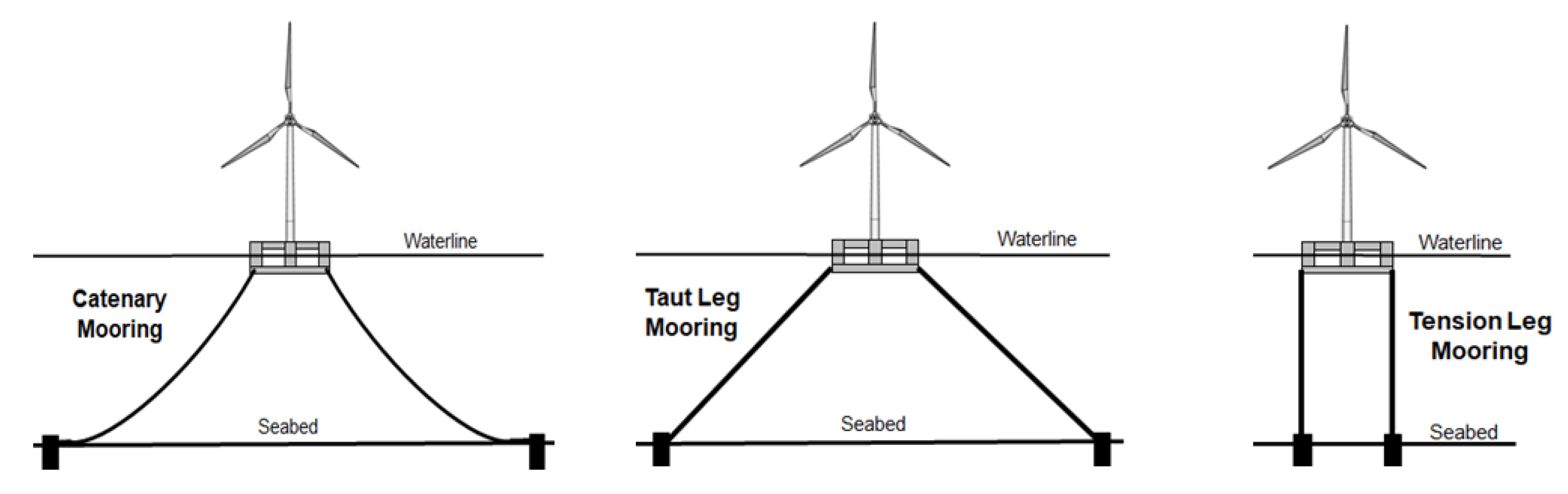
Figure 2.
Schematic of LVTF mooring concept, a) initial position, b) offset position.
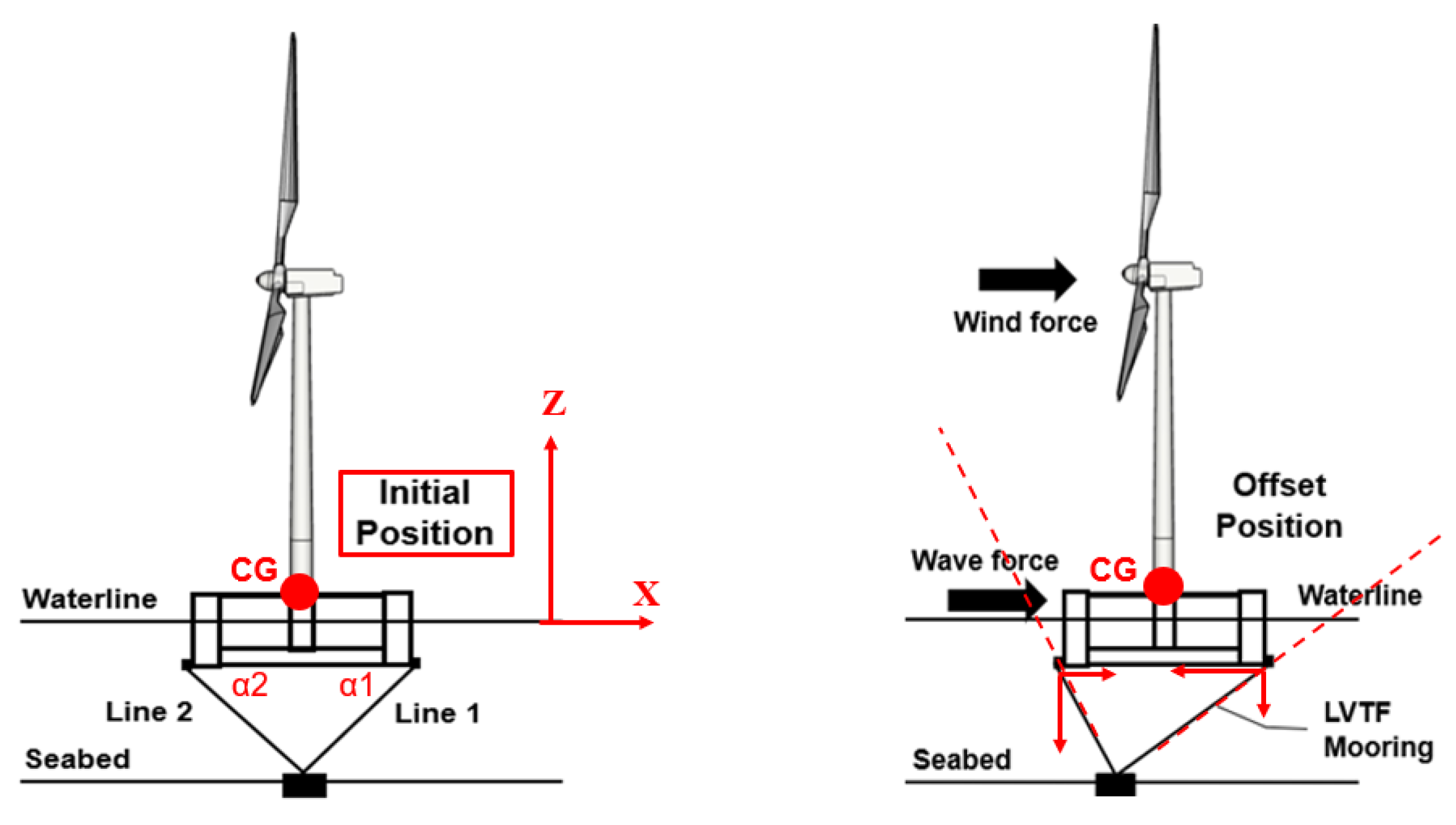
Figure 3.
Comparison of mooring line tensions, LVTF mooring vs. catenary mooring.
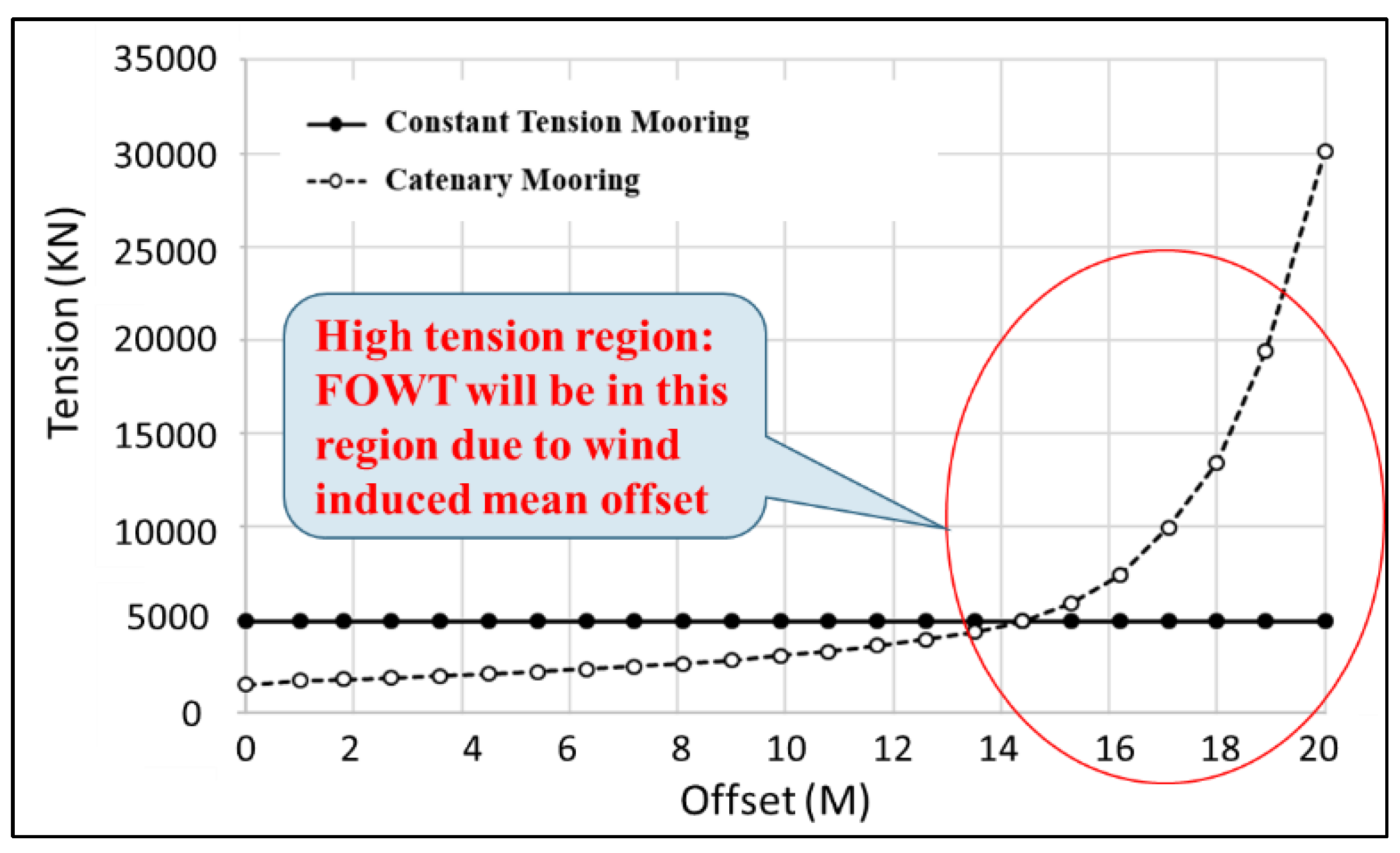
Figure 4.
LVTF mooring system restoring force curves for different water depth.
Figure 5.
LVTF mooring system restoring force vs. offset to water depth ratio.
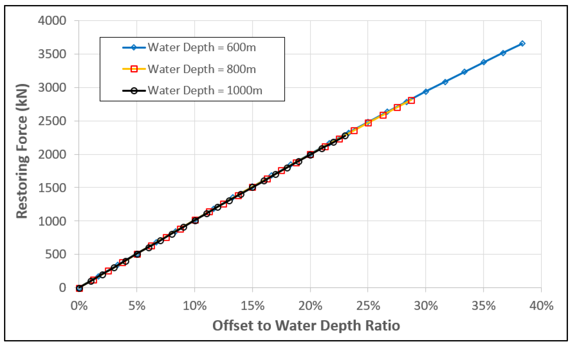
Figure 6.
Definition of LVTF concept with 1 anchor 3 degrees of freedom (surge, sway, heave).
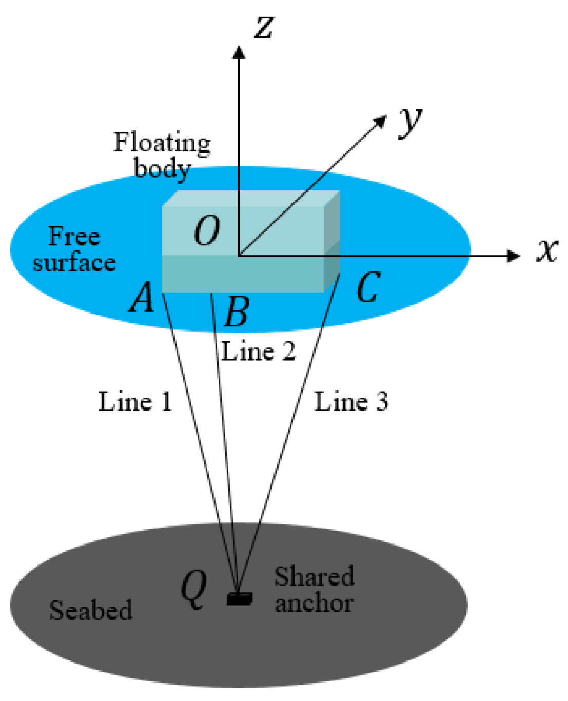
Figure 7.
Schematics of LVTF system of 15 MW semisubmersible FOWT in 200 m and 70 m water depth.
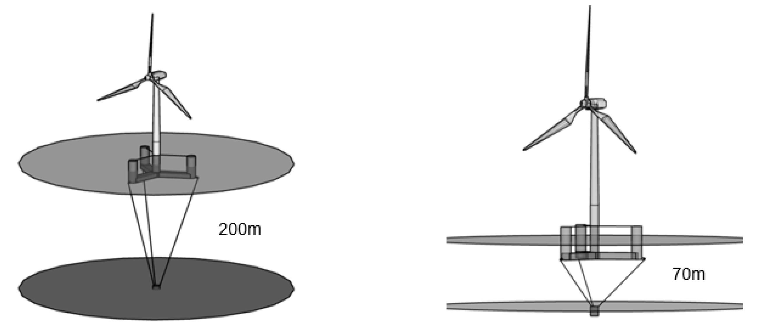
Figure 8.
Horizontal restoring force comparison between catenary and LVTF mooring systems.
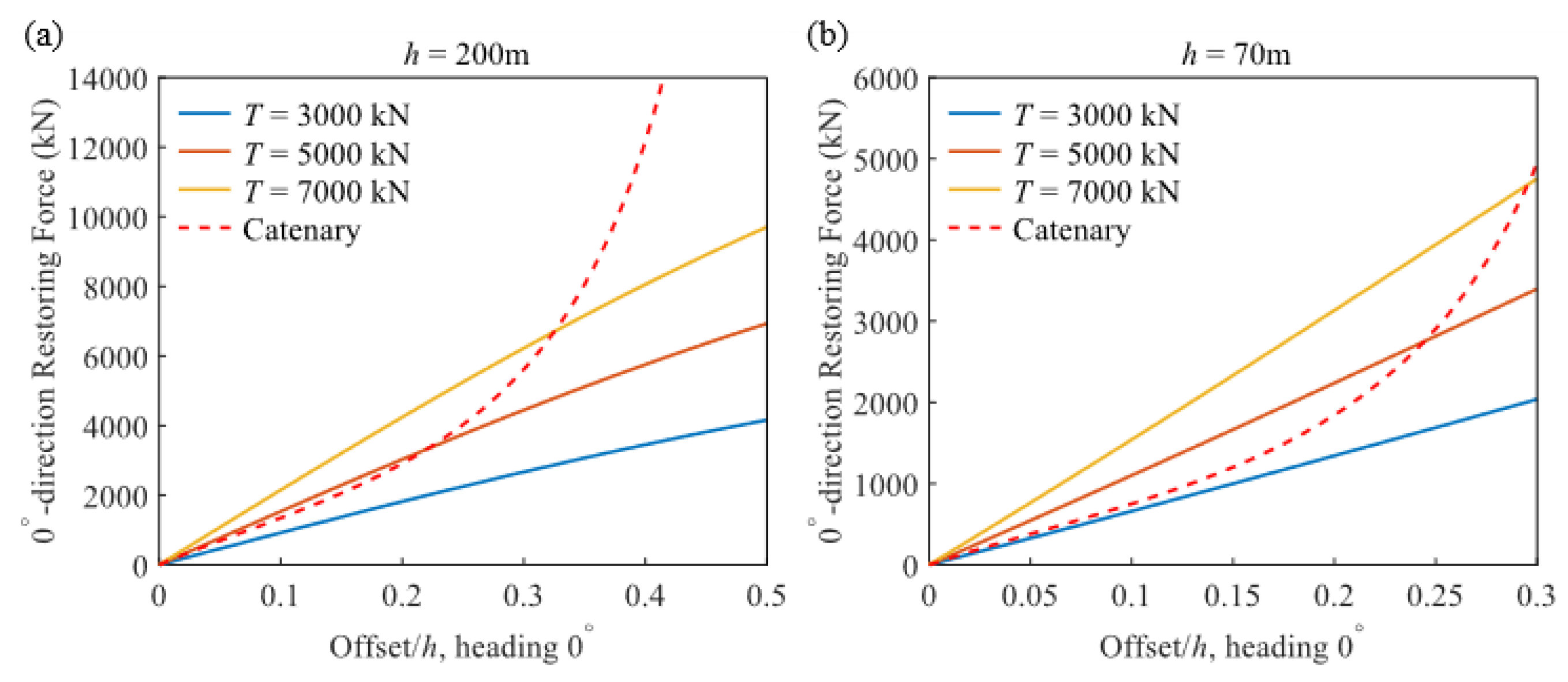
Figure 13.
Schematic of gravity-based passive constant tension mooring concept with PGU.
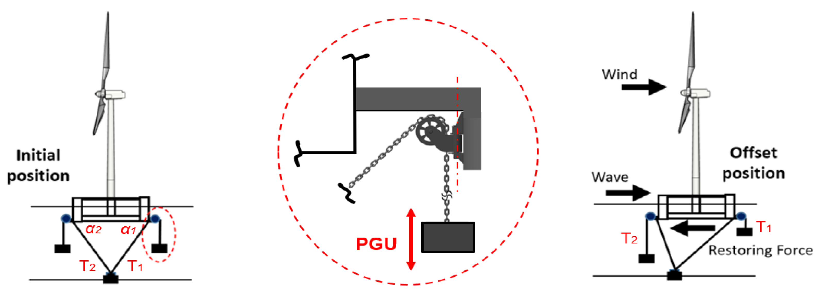
Figure 14.
VISI Spar FOWT, left: in-service configuration; right: scaled test model.
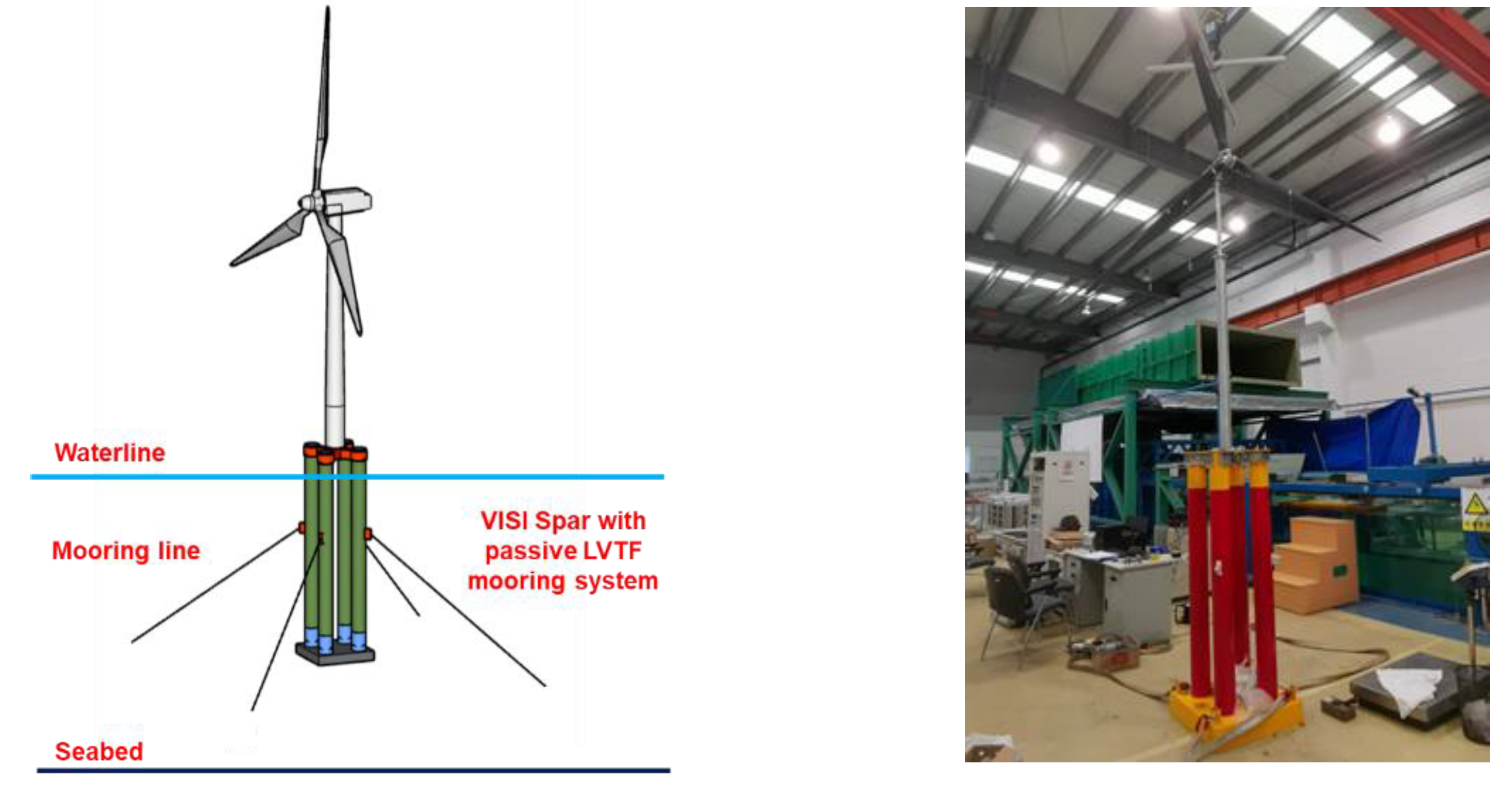
Figure 15.
Illustration of VISI Spar self-installation process: from pre-service mode to in-service mode.
Figure 15.
Illustration of VISI Spar self-installation process: from pre-service mode to in-service mode.
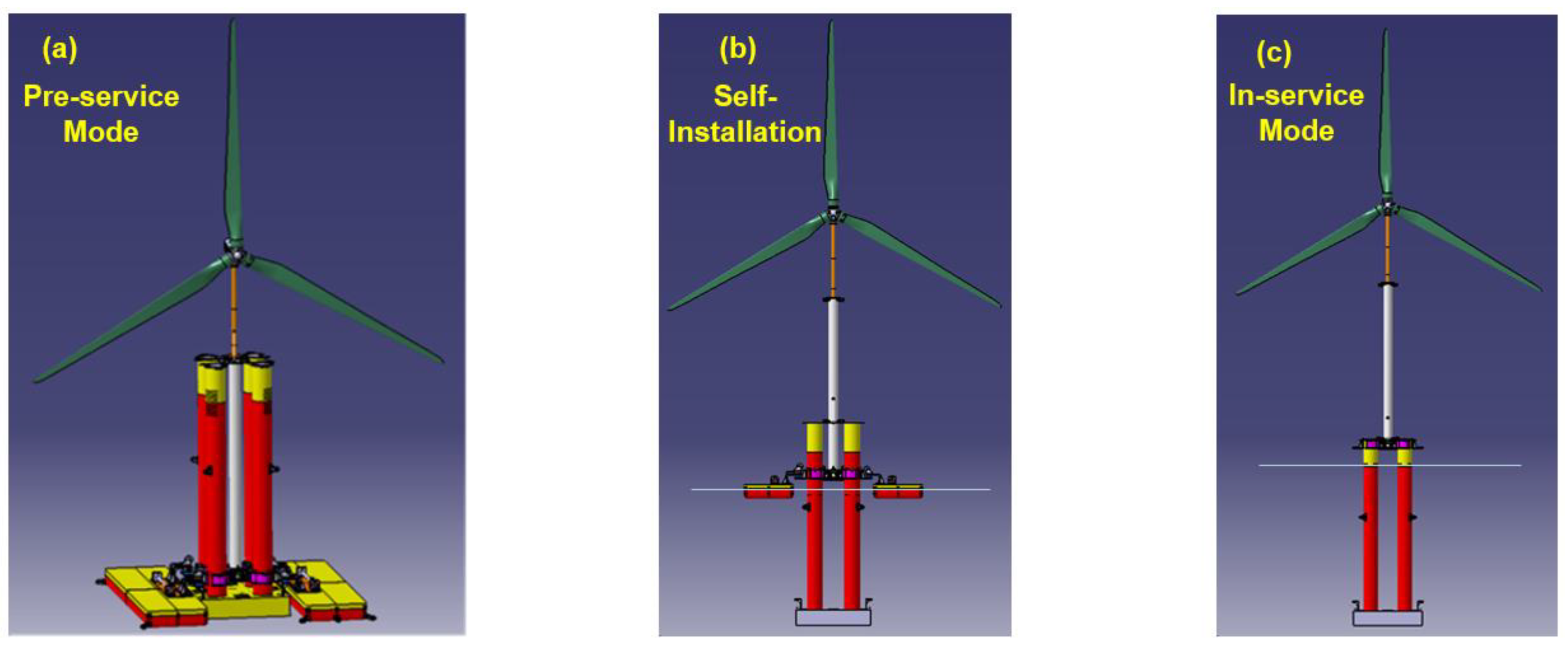
Figure 16.
VISI Spar FOWT with multi-anchor LVTF mooring, (a) initial position, (b) offset position.
Figure 16.
VISI Spar FOWT with multi-anchor LVTF mooring, (a) initial position, (b) offset position.
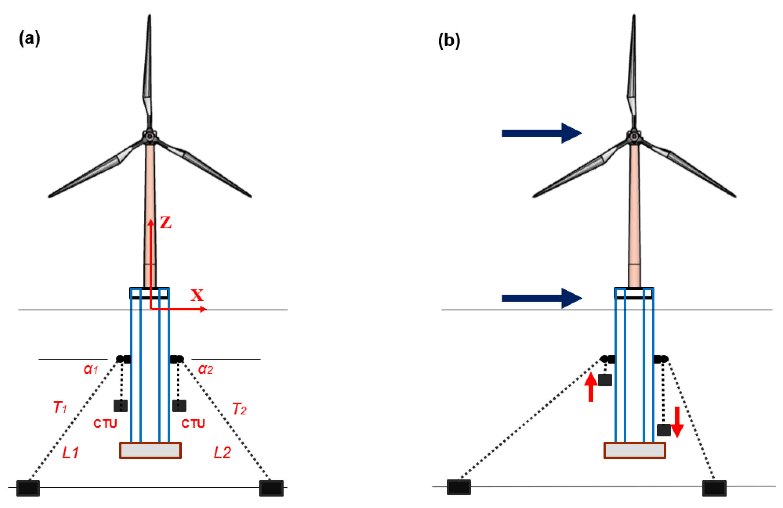
Figure 17.
Overview of VISI Spar wave basin model test facility.
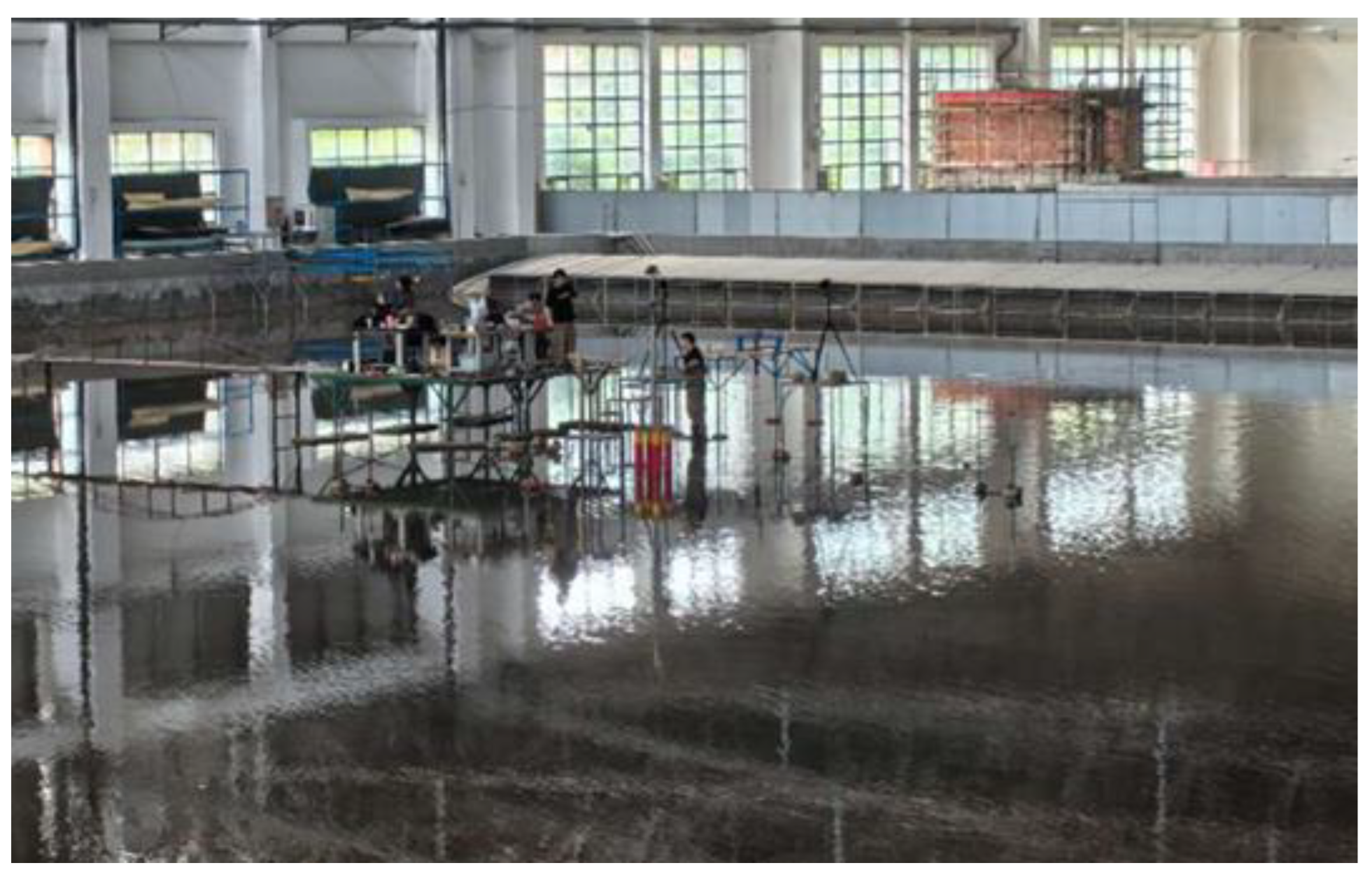
Figure 18.
VISI Spar wave basin model test layout plan.
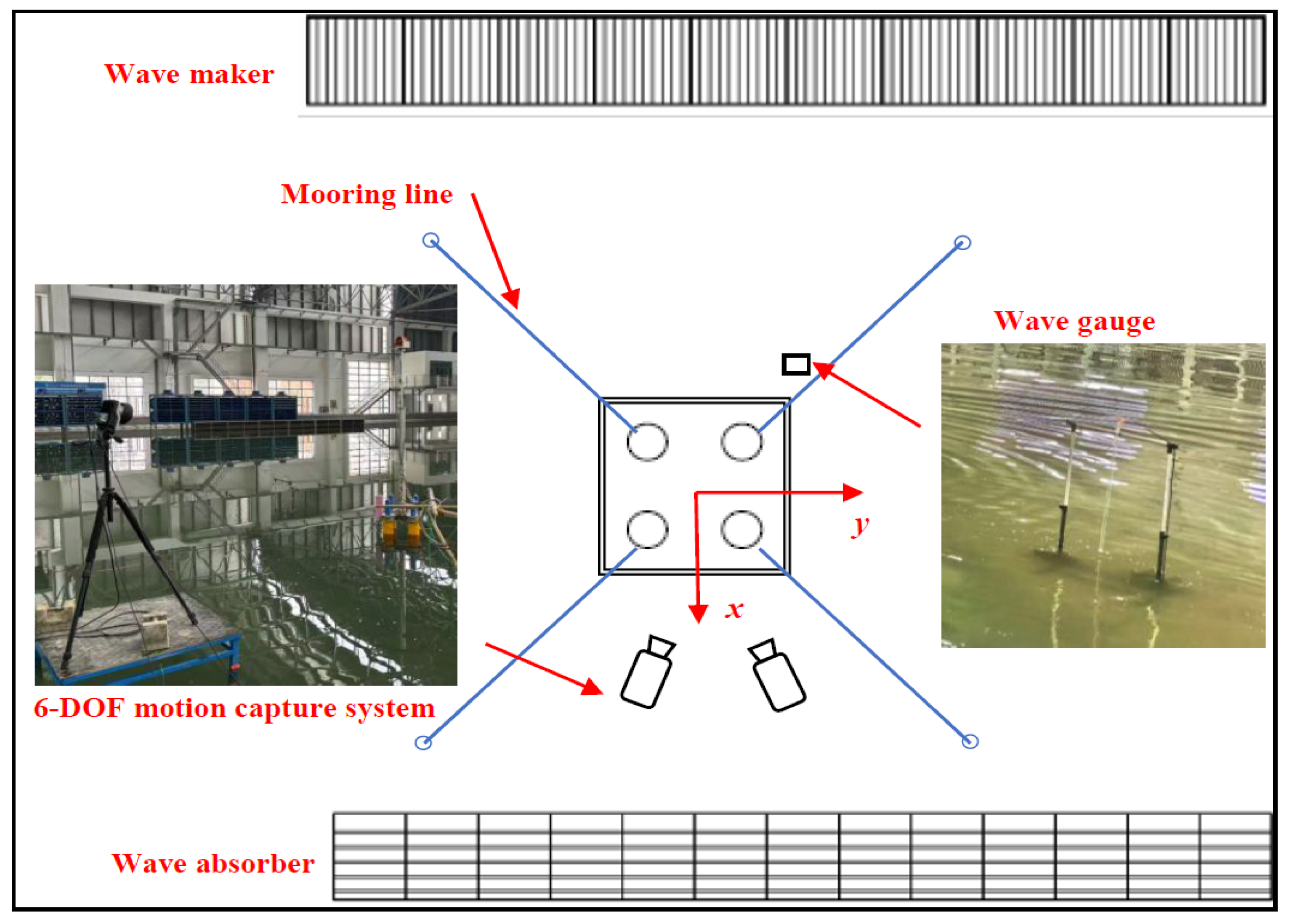
Figure 19.
(a) VISI Spar model, (b) elevation view of the test layout in wave basin.
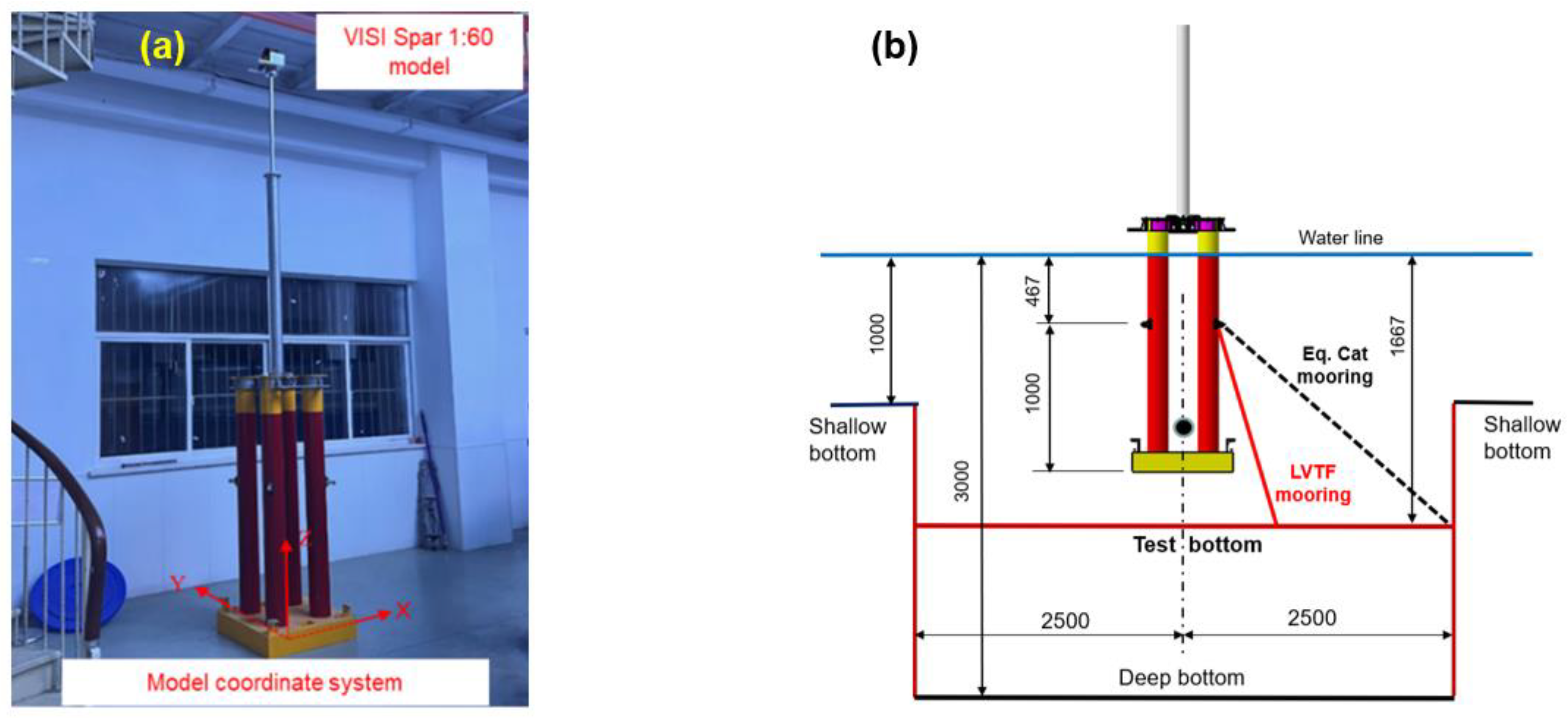
Figure 20.
Plan view of layout of mooring systems in deep pit of wave basin.
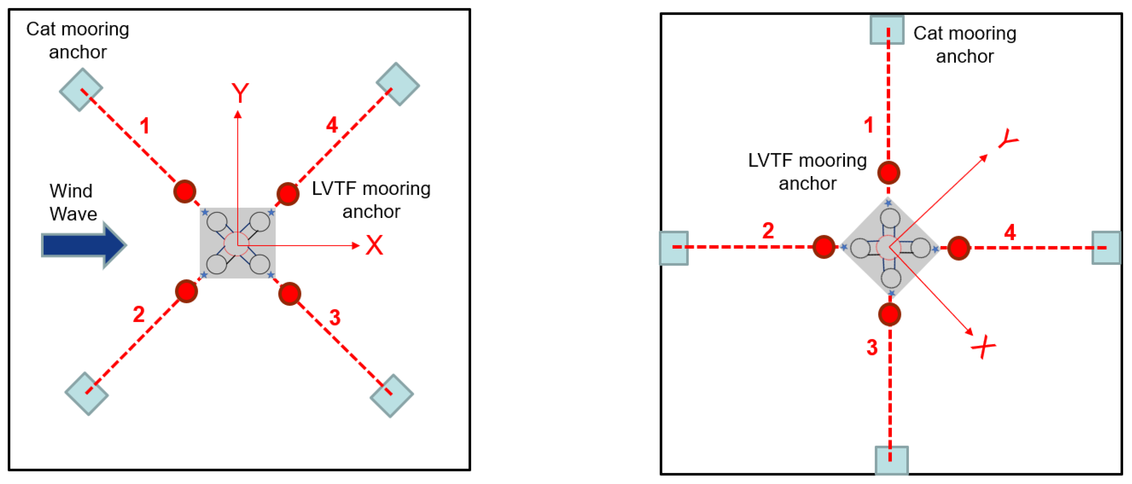
Figure 21.
Aerodynamic wind load generation system for model test.
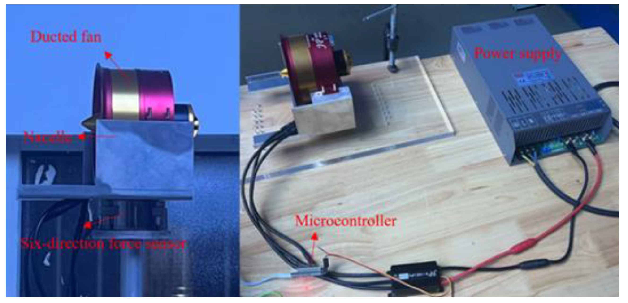
Figure 22.
Comparison of wind thrust time histories (left) and PSD (right).
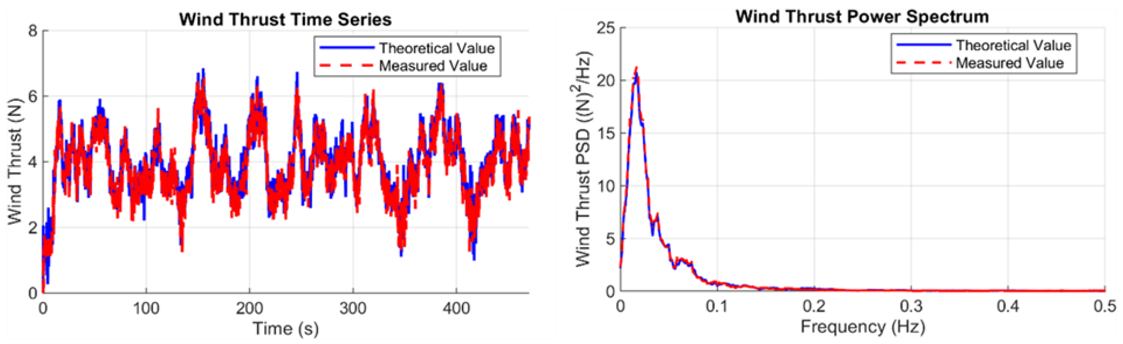
Figure 23.
Mooring line tension vs. offset curve comparison for equivalent mooring system.
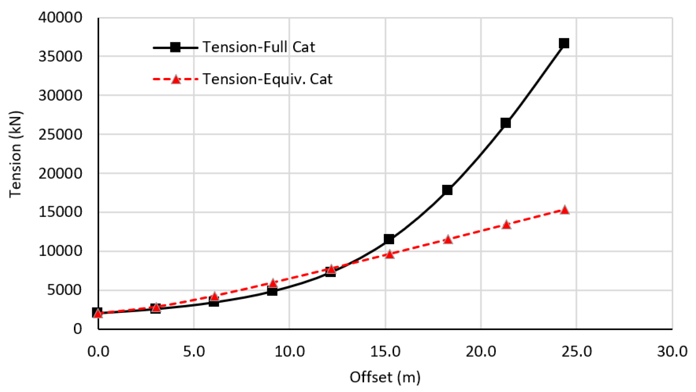
Figure 24.
Free decay test time histories of platform motion natural periods, catenary mooring system.
Figure 24.
Free decay test time histories of platform motion natural periods, catenary mooring system.
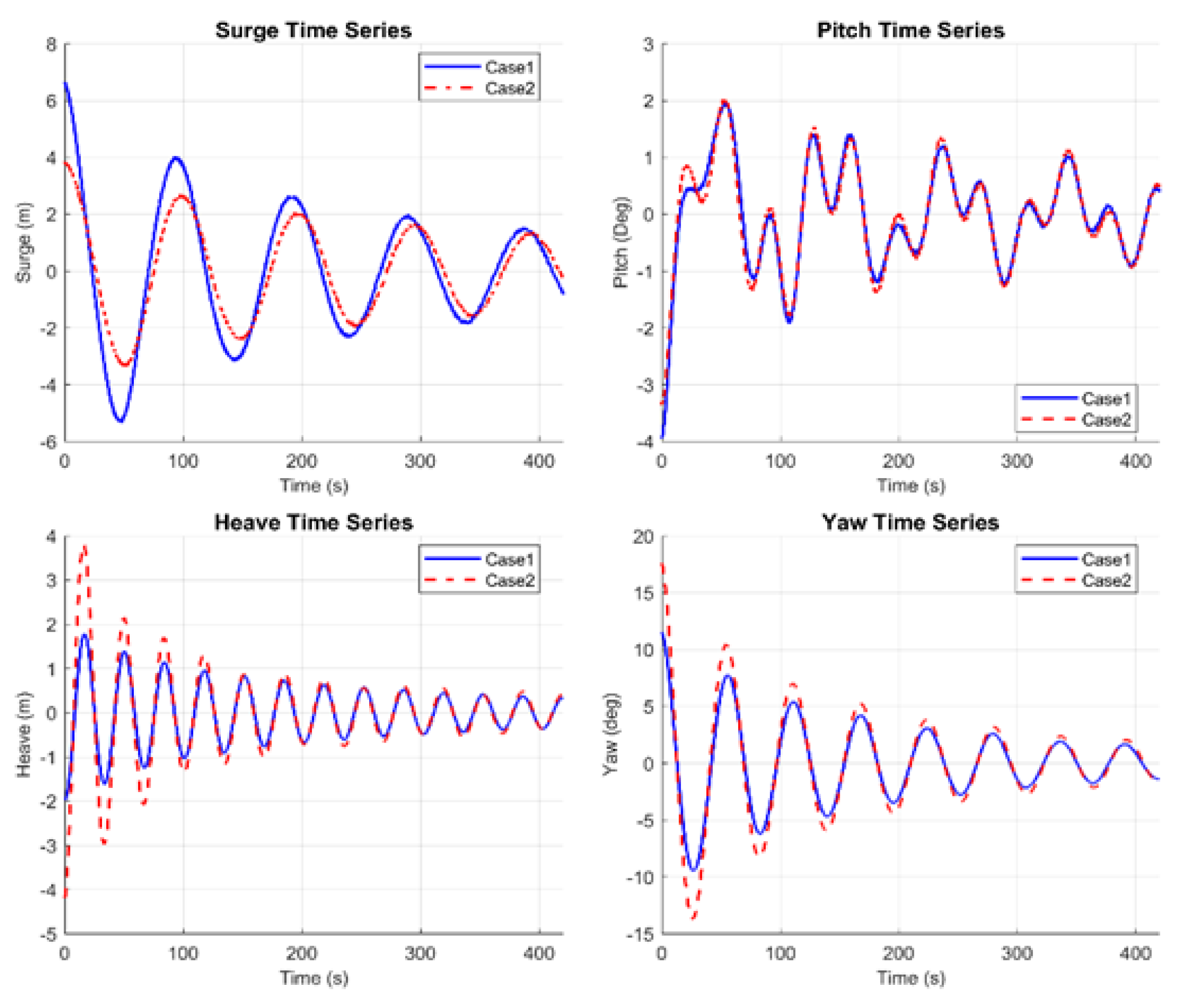
Figure 25.
Time history and PSD of global motions for 0° wave direction, catenary mooring.
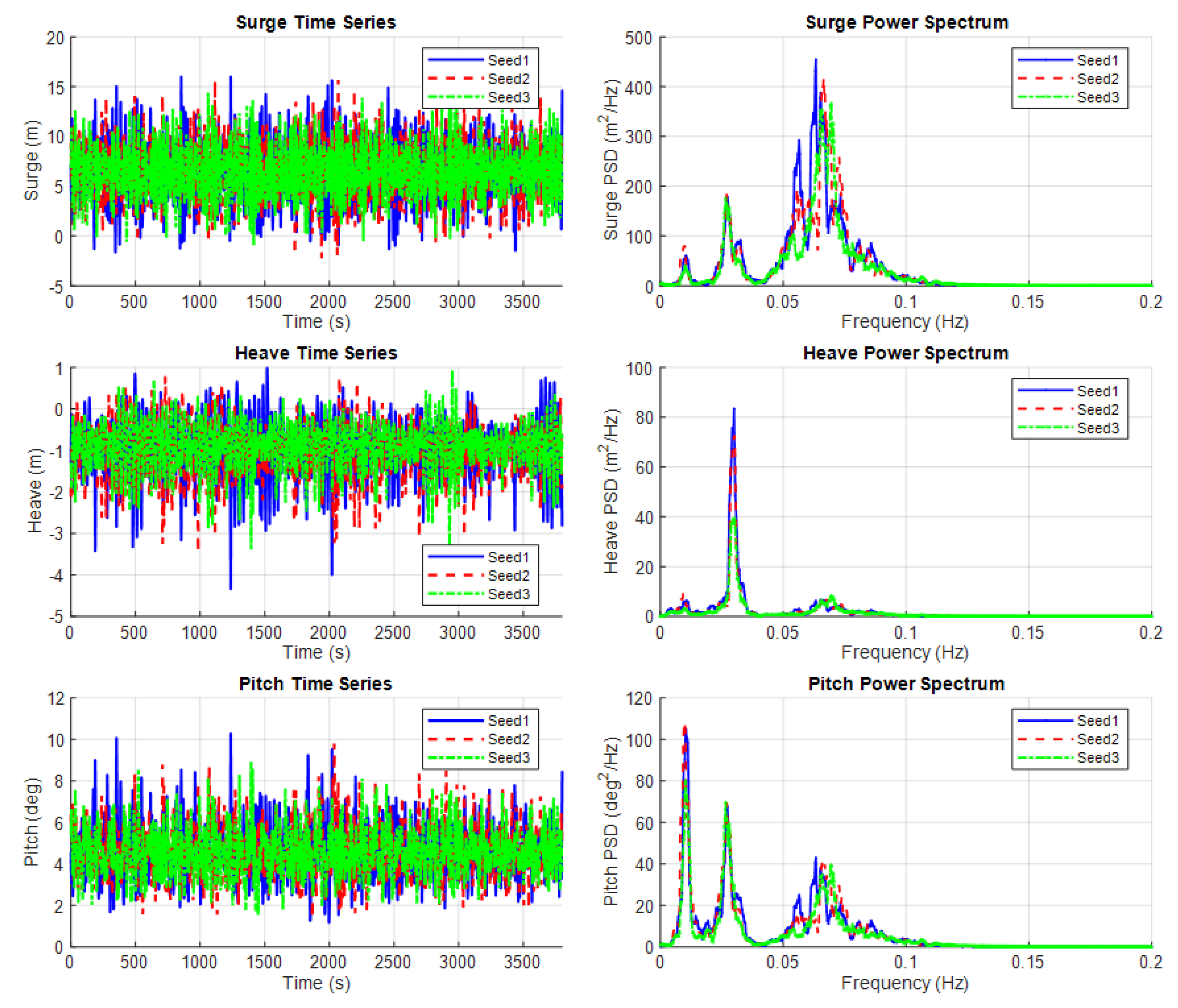
Figure 26.
Time history and PSD of global motions for 45° wave direction, catenary mooring.
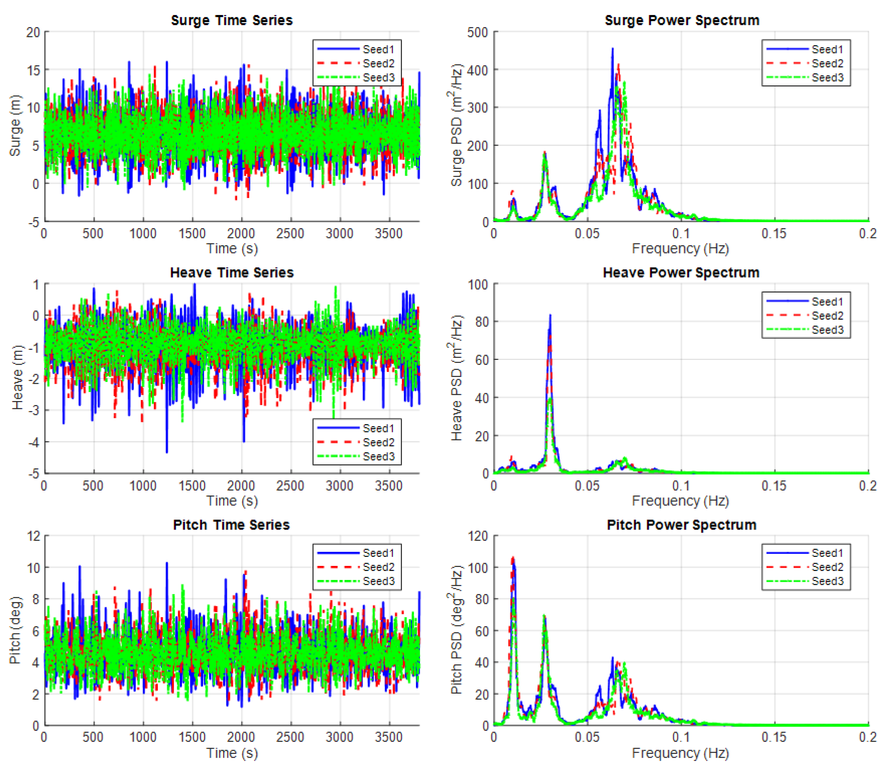
Figure 27.
Time history and PSD of mooring line tension for 0° wave direction, LVTF mooring.
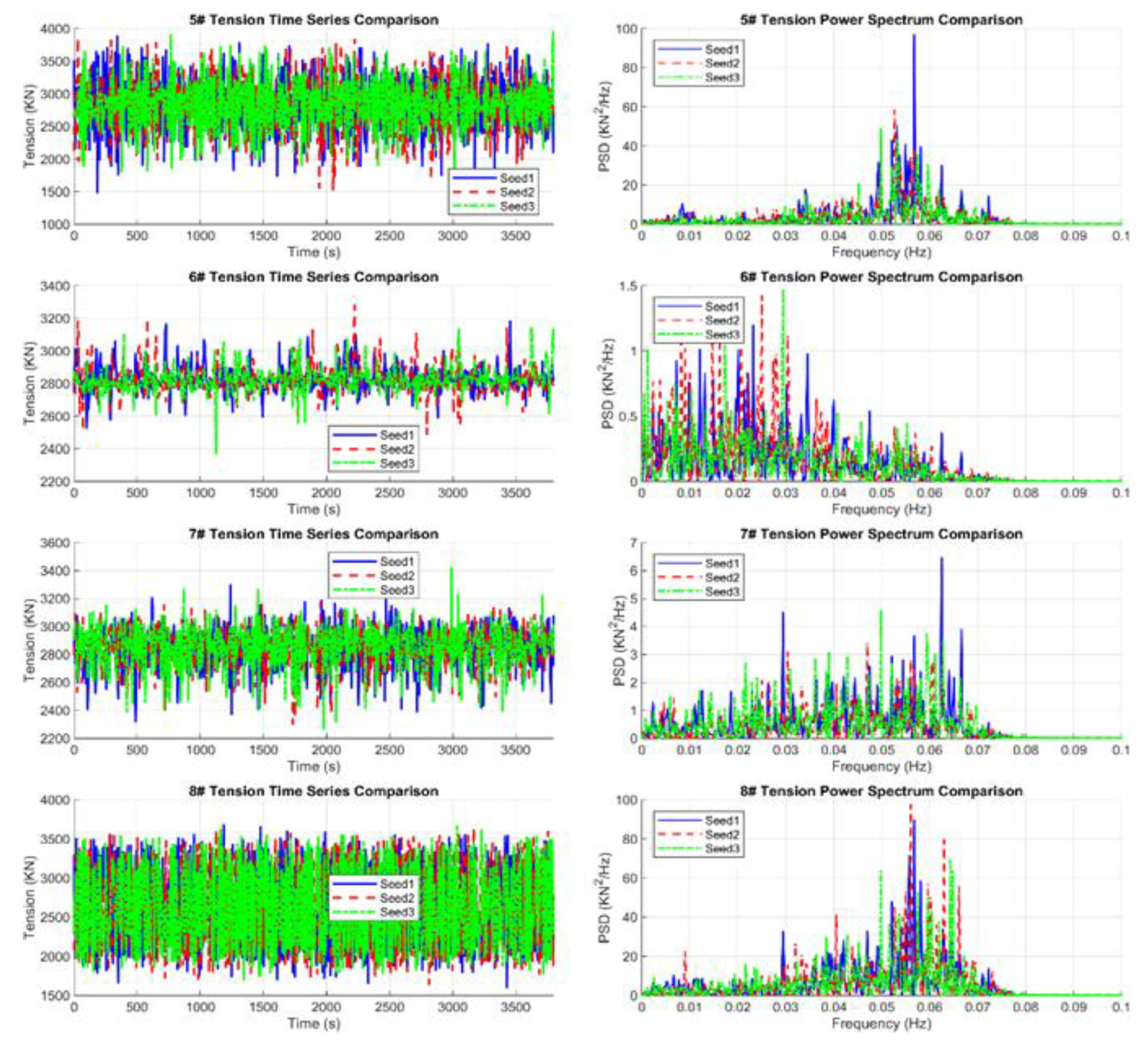
Figure 28.
Time history and PSD of mooring line tension for 45° wave direction, LVTF mooring.
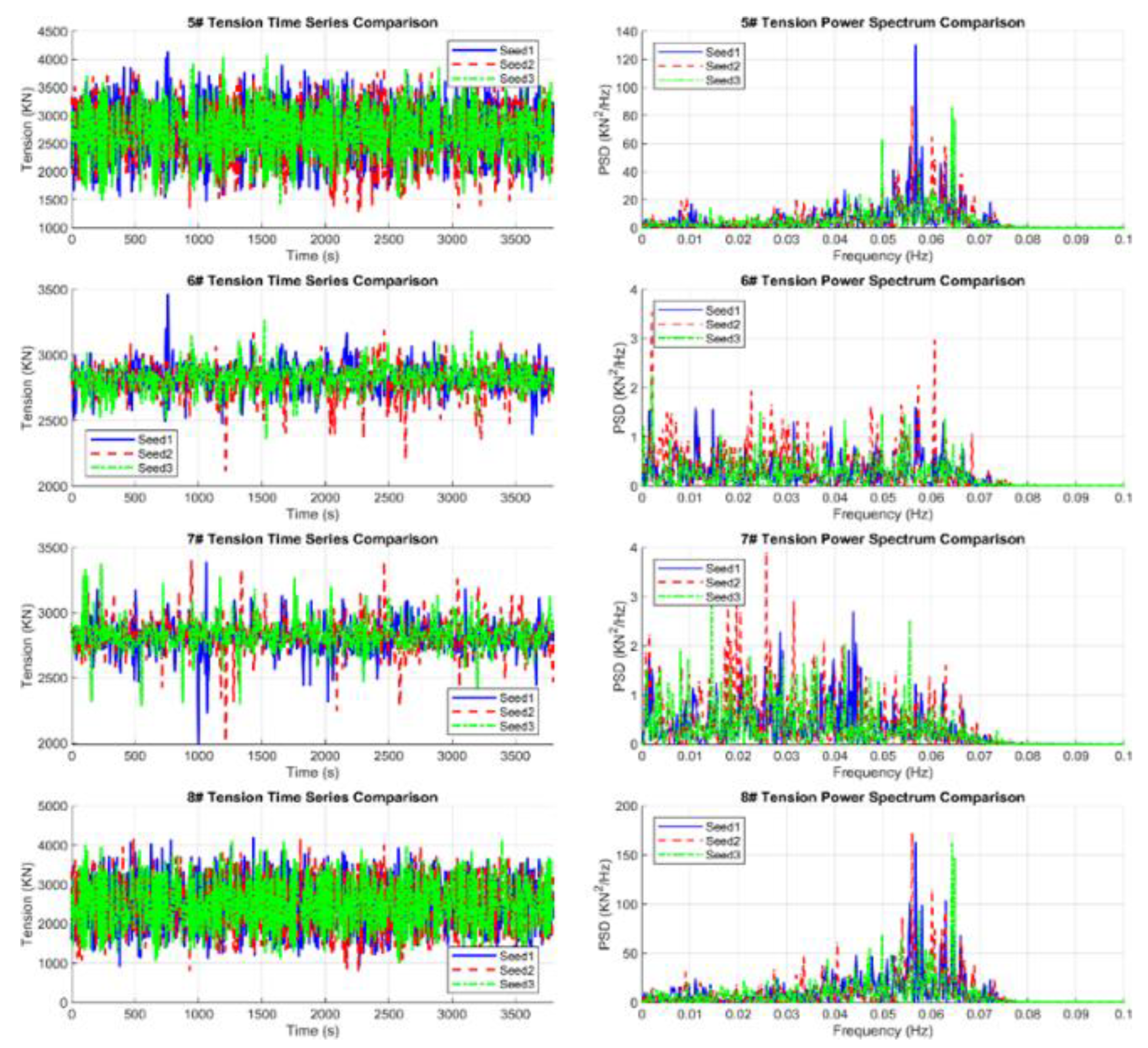
Figure 29.
Time history and PSD of mooring line tension for 0° wave direction, catenary mooring.
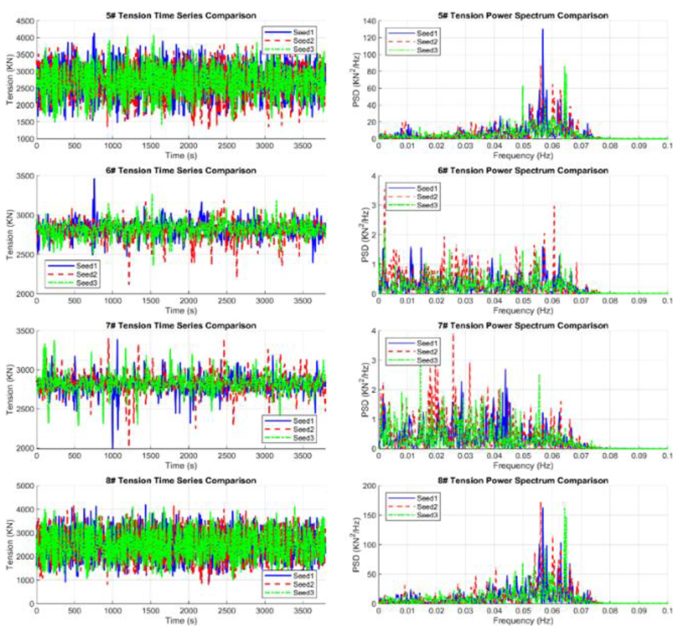
Figure 30.
Time history and PSD of mooring line tension for 45° wave direction, catenary mooring.
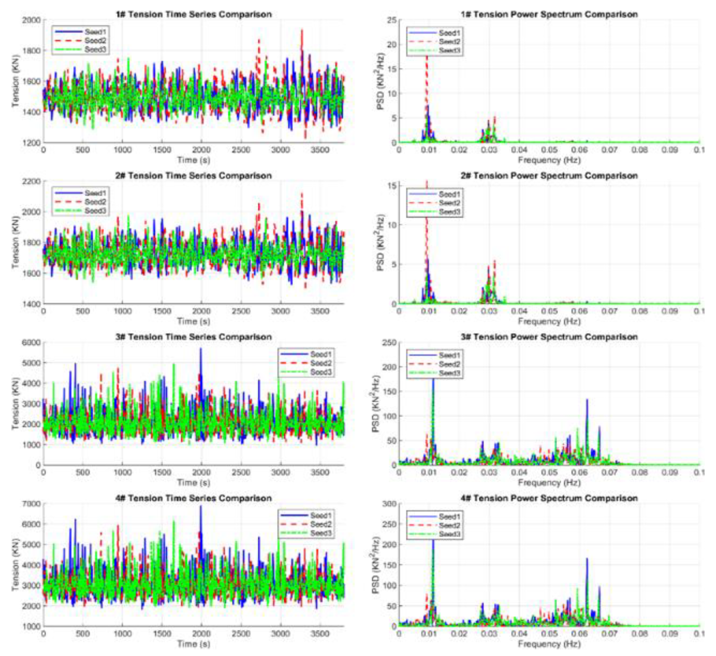

Table 1.
Main dimensions of VolturnUS-S semi-submersible platform.
| Parameters | Unit | Value |
| Length overall | m | 102.13 |
| Width overall | m | 90.13 |
| Outer column spacing | m | 89.63 |
| Outer column diameter | m | 12.50 |
| Mid column diameter | m | 10.00 |
| Mid column – Outer column spacing | m | 51.75 |
| Pontoon width | m | 12.50 |
| Pontoon height | m | 7.00 |
| Draft | m | 20.00 |
| Freeboard | m | 15.00 |
Table 2.
Metocean data and main dimensions of the VISI Spar FOWT.
| Model scale 1:60 | Unit | Prototype | Model |
| Water depth | m | 100 | 1.667 |
| 50-year typhoon: Significant wave height | m | 11.5 | 0.192 |
| Wave spectral peak period | s | 14.7 | 0.898 |
| Hull column diameter | m | 8.0 | 0.133 |
| Design draft | m | 88.0 | 1.467 |
| Nacelle height | m | 150.0 | 2.500 |
| Overall height from platform keel to nacelle | m | 238.0 | 3.967 |
| LVTF mooring system CTU weight | kg | 325000 | 1.500 |
Table 3.
Model test case matrix for typhoon conditions.
| Test case number | Mooring system | Wave heading |
| 1 | Catenary | 0° |
| 2 | Catenary | 45° |
| 3 | LVTF | 0° |
| 4 | LVTF | 45° |
Table 4.
VISI Spar global motions with catenary mooring - 0° wind-wave heading.
| Parameter | Unit | Max | Min | Mean | St. Dev. |
| Surge | m | 15.42 | -1.59 | 6.56 | 2.69 |
| Sway | m | 1.66 | -2.95 | -0.52 | 0.76 |
| Heave | m | 0.03 | -4.88 | -1.82 | 0.62 |
| Roll | deg | 1.49 | -0.95 | 0.30 | 0.42 |
| Pitch | deg | 9.67 | 1.37 | 4.60 | 1.18 |
| Yaw | deg | 4.79 | 0.47 | 2.66 | 0.73 |
| Nacelle Acc-X | m/s2 | 1.53 | -1.37 | 0.00 | 0.41 |
Table 5.
VISI Spar global motions with catenary mooring - 45° wind-wave heading.
| Parameter | Unit | Max | Min | Mean | St. Dev. |
| Surge | m | 14.96 | -1.73 | 6.26 | 2.67 |
| Sway | m | 2.01 | -2.44 | -0.23 | 0.72 |
| Heave | m | 0.94 | -4.94 | -1.85 | 0.65 |
| Roll | deg | 1.72 | -0.74 | 0.60 | 0.38 |
| Pitch | deg | 10.19 | 1.34 | 4.87 | 1.25 |
| Yaw | deg | 6.50 | 1.70 | 4.02 | 0.84 |
| Nacelle Acc-X | m/s2 | 1.56 | -1.38 | 0.00 | 0.43 |
Table 6.
Global motions with LVTF mooring - 0° wind-wave heading.
| Parameter | Unit | Max | Min | Mean | St. Dev. |
| Surge | m | 22.95 | 4.57 | 13.93 | 2.60 |
| Sway | m | 0.20 | -5.64 | -2.04 | 1.00 |
| Heave | m | -0.04 | -4.11 | -1.50 | 0.60 |
| Roll | deg | 1.70 | -0.83 | 0.25 | 0.40 |
| Pitch | deg | 12.67 | 3.27 | 7.32 | 1.24 |
| Yaw | deg | 3.54 | 0.79 | 2.04 | 0.47 |
| Nacelle Acc-X | m/s2 | 1.61 | -1.53 | -0.58 | 0.43 |
Table 7.
Global motions with LVTF mooring - 45° wind-wave heading.
| Parameter | Unit | Max | Min | Mean | St. Dev. |
| Surge | m | 21.59 | 3.89 | 13.37 | 2.40 |
| Sway | m | 0.81 | -2.55 | -1.21 | 0.45 |
| Heave | m | 0.97 | -3.44 | -1.34 | 0.63 |
| Roll | deg | 2.15 | -0.24 | 0.99 | 0.32 |
| Pitch | deg | 11.45 | 3.47 | 6.78 | 1.04 |
| Yaw | deg | 7.92 | 0.79 | 4.19 | 0.91 |
| Nacelle Acc-X | m/s2 | 1.50 | -1.52 | 0.00 | 0.43 |
Table 8.
Natural periods of the VISI Spar with different mooring systems.
| Parameter | Unit | LVTF Mooring | Catenary Mooring |
| Surge / Sway | s | 93.15 | 97.91 |
| Heave | s | 29.12 | 33.93 |
| Roll / Pitch | s | 86.33 | 30.52 |
| Yaw | s | 47.99 | 56.82 |
Table 9.
Mooring line tension statistics of LVTF mooring.
| Tension /No. /heading | Unit | Max | Min | Mean | STD |
| Ten., Line 2, 0° | kN | 4035.7 | 1385.8 | 2700.5 | 602.3 |
| Ten., Line 3, 0° | kN | 4165.1 | 908.8 | 2501.5 | 792.4 |
| Ten., Line 2, 45° | kN | 3906.1 | 1600.8 | 2838.5 | 468.2 |
| Ten., Line 3, 45° | kN | 3661.6 | 1646.1 | 2638.1 | 611.8 |
Table 10.
Mooring line tension statistics of catenary mooring.
| Tension /No. /heading | Unit | Max | Min | Mean | STD |
| Ten., Line 2, 0° | kN | 3798.6 | 1667.4 | 2387.8 | 356.1 |
| Ten., Line 3, 0° | kN | 3607.1 | 1651.6 | 2236.1 | 277.6 |
| Ten., Line 2, 45° | kN | 2031.6 | 1518.4 | 1727.1 | 83.8 |
| Ten., Line 3, 45° | kN | 6319.7 | 1870.0 | 3079.7 | 715.0 |
Table 11.
Comparison of key model test results of extreme values (positive or negative).
| Extreme value (+/-) | Unit | LVTF - 0° | LVTF - 45° | Catenary - 0° | Catenary - 45° |
| Surge | m | 22.95 | 21.59 | 15.42 | 14.96 |
| Sway | m | -3.03 | -2.55 | -2.95 | -2.44 |
| Heave | m | -3.23 | -3.44 | -4.88 | -4.94 |
| Roll | deg | 1.70 | 2.15 | 1.49 | 1.72 |
| Pitch | deg | 12.67 | 11.45 | 9.67 | 10.19 |
| Yaw | deg | 3.54 | 7.92 | 4.79 | 6.50 |
| Nacelle acc-X | m/s2 | 1.61 | -1.52 | 1.53 | 1.56 |
| Line tension | kN | 4165.1 | 3906.1 | 3798.6 | 6319.7 |
Table 12.
Economic analysis of mooring systems – catenary vs. LVTF cost comparison.
| Item | Unit | Catenary Mooring | LVTF Mooring |
| Number of Lines | 4 | 4 | |
| Anchor Radius | m | 950.0 | 70.0 |
| Chain Length/Line | m | 978.5 | 105.8 |
| Chain Weight | ton | 2681.1 | 290.0 |
| Chain Cost | Mil. USD | 4.02 | 0.43 |
| Anchor Cost | Mil. USD | 1.80 | 0.66 |
| CTU/PGU Cost | Mil. USD | N/A | 0.33 |
| Installation Cost | Mil. USD | 3.00 | 1.50 |
| Total Installed Cost | Mil. USD | 8.82 | 2.92 |
Disclaimer/Publisher’s Note: The statements, opinions and data contained in all publications are solely those of the individual author(s) and contributor(s) and not of MDPI and/or the editor(s). MDPI and/or the editor(s) disclaim responsibility for any injury to people or property resulting from any ideas, methods, instructions or products referred to in the content. |
© 2026 by the authors. Licensee MDPI, Basel, Switzerland. This article is an open access article distributed under the terms and conditions of the Creative Commons Attribution (CC BY) license (http://creativecommons.org/licenses/by/4.0/).
Copyright: This open access article is published under a Creative Commons CC BY 4.0 license, which permit the free download, distribution, and reuse, provided that the author and preprint are cited in any reuse.