

Submitted:
17 September 2026
Posted:
17 September 2026
You are already at the latest version
Abstract
Large format additive manufacturing using recycled plastic pellets marks a significant evolution in 3D printing, advancing both fabrication methods and circular economy goals. While it remains underutilized due to the inherent variability and unpredictability of the recycled material, difficult to manage in the context of product design and engineering, the experiences of New01Bike, Amarcord and OneLineTwoCoils show that embracing this unpredictability through iterative feedback loops drives manufacturing innovation and creates cult objects. The proposed approach involves fusing PC pellets with a screw industrial extruder, using parametric modeling and part redesign to mitigate warping, and employing Adaptive Layer Height slicing to unlock new geometries and reduce scrap.
Keywords:
large format additive manufacturing
; warping
; computational design
; adaptive layer height
; recycled polymers
; pellets
; screw extruder
; RAM
; robotic additive moulding
1. Introduction
Large Format Additive Manufacturing (LFAM) of recycled pellets represents a major advancement in 3D printing (3DP) technology, both for improving existing plastic processing methods and for pushing forward circular economy practices.
The primary advantage of using a six degrees of freedom (6dof) robotic arm over a three-axis Cartesian 3D printer lies in the orientation control of the end-of-arm tool (EOAT) through rotations about the x-, y-, and z-axes. In the LFAM industry, robotic arms leverage their kinematic flexibility to overcome the constraint of printing on a flat build plane. This enables non-planar AM, reduces the need for support material, and facilitates the fabrication of complex spatial geometries through techniques such as Adaptive Layer Height (ALH). Following ruled surfaces, rails, and double-curved geometries in space, layer orientation may align with the principal stress paths, enhancing mechanical performance by form, reducing additional supports or infill.
After solving the kinematics, the immediate challenge that LFAM faces is the development of a functional extrusion system, fundamental to achieving high-quality printed parts. In fact, being complex thermolabile molecules behaving as poor conductors, polymers require a stable heat administration that does not compromise their properties; controlled melting and cooling—coupled with the preservation of properties of the material—is key to manage the polymer’s mechanical response after extrusion.
Extruder design and manufacturing represents a long-term, knowledge-intensive discipline: there is no universal extruder, as seemingly minor design adjustments can have a major impact on process stability and material performance. A one-size-fits-all solution inevitably leads to compromises, limiting the ability to process demanding materials such as recycled polymers, PC or PEEK.
Indeed, many LFAM systems adopt simplified melting units for particular thermoplastics rather than fully optimized extrusion systems. Nonetheless, thanks to the polymer manufacturer’s control over virgin material properties, LFAM systems with simplified extrusion units may deliver reliable print quality and reach high extrusion speeds, especially when the material is characterized. To say "characterized" means that material properties have been measured and documented, and the testing phase has determined: morphological features (e.g., particle size, structure), physical properties (density, tensile strength, elasticity, viscosity), chemical composition (presence of additives, contaminants), thermal properties (melting point, softening point, thermal degradation), and its environmental impact (e.g., life-cycle analysis, emissions from reuse).
In the case of recycled pellets, this processing knowledge is difficult to infer or reconstruct, yet it is essential for achieving consistent extrusion performance, particularly when using simplified extrusion units. Inadequate extrusion conditions can result in loss of molecular weight, thermal degradation, oxidation, unstable flow, lower isotropy, and process instability. Properly designed industrial extruders, on the other hand, are able, through the sequential arrangement of temperature-controlled zones, to contain shear and thermal stress, leading to robust control of throughput and pressure stability, even over long print times, while transforming regular pellets into molten and plastified polymer.
Due to a combination of technical and regulatory limitations [1,2], market readiness in Europe for AM of recycled polymers in pellet form is relatively low at the present, with limited demand and marginal industrial uptake compared to AM techniques using virgin polymers and metal powders [3]. The EU Regulation (2022/1616) on recycled plastic materials and articles requires the use of authorized recycling technologies [4,5]. However, obtaining authorization involves multiple assessments which, while significantly increasing costs and environmental impact due to additional logistics, can delay or even hinder the adoption of novel processes—particularly in sectors with long-term asset creation and significant societal impact, such as construction, energy & mobility.
Printing with recycled blends promotes circular economy with the bottom-up optimization of printing parameters and the material characterization of potentially endless polymer-based scrap material [1]—drifting away from, or at least complementing, the classic top-down approach: engineering a new thermo-polymer from scratch. Nonetheless, the difficulties of modeling beforehand the printing process, makes achieving consistent results across different machines and 3DP projects problematic. Since warping, extrusion quality, shock resistance, delamination of the molded part (see a clear example of warping and consequent delamination in Figure 1) are not easily inferable by the sole material datasheet or from a finite element method (FEM), extensive testing and a bottom-up characterization of the material is often indispensable at the batch level.
Extruder design and process optimization require expertise in polymer rheology, heat transfer, screw design, material science, and process control, often accumulated over decades of trial and error. An industrial extruder equipping a high-payload robotic arm enables the production of large-scale furniture, but also of full housing components or self-bearing walls with recycled polymers.
Recycled plastic comes either in the form of PIR (Post-Industrial Recyclate) plastic pellets—also referred to as “Pre-consumer material” by DIN EN ISO 14021:2016 [6]—which are residues coming from the waste stream of manufacturing processes, generally from factory scrap, or in the form of PCR (Post-Consumer Recyclate) pellets, which are made from used plastic products collected after consumer use.
Whereas PCR adoption is gaining ground in the framework of EU’s sustainability goals [7,8], PIR materials are often preferred over PCRs in applications that demand high performance, reliability, and regulatory compliance. Because of their traceability and quality control, PIRs are usually more consistent in composition and cleaner, as they originate from—or are certified by—known sources. PCRs tend to be variably contaminated due to mixed input materials, and they often contain critical foreign fractions, like food residues or labels, reducing mechanical qualities and leavening post-processing costs. Thermo-mechanical reprocessing, as well as other factors such as exposure to UV-light, could result in waste streams with degraded properties.
Therefore, from automotive and racing, to energy and aerospace, LFAM for the manufacturing of high-complexity parts is either being discarded from the beginning as being too costly and too risky [9], or is mostly employing virgin materials [10,11,12] to exclude a layer of complexity and variability of the print caused by material unpredictability. Most capital-intensive industries with significant value-added per unit produced are less sensitive to raw material cost savings while being more concerned with performance and reliability—which influences their appetite for selecting recycled materials. Meanwhile, case studies [13,14,15,16] from architecture and furniture design show promising new applications using robotic extrusion and large-scale pellet systems. The commercial ecosystem for LFAM for furniture, housing, or architecture is still evolving.
If LFAM were reframed as Robotic Additive Moulding (RAM) to emphasize extrusion hardware and polymer processing, it may close the circle: leveraging polymer processing and moulding expertise to effectively process recycled thermoplastics. Although robotic kinematics can now be integrated relatively easily using readily available tools, the design of robust extrusion hardware requires specialized knowledge that directly influences material quality and process reliability. As industrial robots, controllers, simulation software, and associated expertise have become increasingly accessible, advanced polymer processing expertise remains comparatively scarce and continues to represent a key bottleneck.
To invoke Christopher Alexander’s Notes on the Synthesis of Form—if the geometric unpredictability of recycled material is indeed the set of external forces to which form must respond in order to exist [17], are there design principles, or at least heuristics, that would allow form to counterbalance these forces and become more reproducible?
With Gimac Int. S.r.l. and eXgineering SA, INDEXLAB has carved a niche within Design for Additive Manufacturing (DfAM) that is employing computational tools to LFAM with recycled blends [18], to accelerate the innovation cycle of high-performance, sustainable manufacturing, exchanging process parameters and fine-tuning Gimac Int. S.r.l.’s proprietary extrusion technology for robotic fabrication pipelines.
INDEXLAB is a Polytechnic of Milan research laboratory based in Lecco, Lombardy, which explores the future of robotic manufacturing in close collaboration with industrial partners and forward-looking companies. Interpreting technological innovation as the main hinge between academia and industry, in the last ten years INDEXLAB has been interested in robotic fabrication at large, preparing the market for the verge of new disruptive models and production processes.
Leveraging on such long-term expertise in extruder design and melt-processing optimization for challenging materials such as PC, PEEK, and recycled polymers, INDEXLAB combines this core know-how with advanced robotic manipulation and path-planning expertise to enable robust and repeatable manufacturing. Through applied research and testing, these advancements enables the production of otherwise impossible to manufacture cult objects made of recycled plastic that highlight the innovations and pave the way for potential spin-offs.
To demonstrate the technology’s potential and the opportunities for innovative products to reach the market, the article discusses three projects executed via RAM of recycled pellets, developed and manufactured in INDEXLAB from 2021 to 2023, during the R&D partnership with Gimac Int. S.r.l. and eXgineering SA that began in 2019.
The structure of the paper is as follows: Section 2 provides an overview of the materials and methods: the primary hardware and software used, the projects’ background with some foundational assumptions, and sets the stage for the analysis that follows. Section 3 outlines the results: the implementation strategy, emphasizing key findings, for each project. Lastly, Section 4 discusses the outcomes, considering the broader implications of the work, acknowledging its limitations, and suggesting future research.
2. Materials and Methods
The article examines three projects that convert material unpredictability from constraint to design opportunity, highlighting some insights derived from this form-process iterative feedback loop. Apart from sharing the same production hardware and software, New01Bike, Amarcord and OneLineTwoCoils also share other common features which, for clarity, are organized in subsections.
Fusing PC pellets with a screw industrial extruder, using parametric modeling to mitigate warping, employing ALH slicing to unlock new geometries and reduce scrap: these features embody the principles of design-for-fabrication, where—as in nature—form co-evolves iteratively with recycling processes of the material, and where the unpredictability of the material is an actual methodological driver rather than mere technical shortcoming.
Nonetheless, while these common assumptions do provide a rationale for interpreting the discussed projects, the authors do not mean to present a fail-proof method, merely some design choices to work with uncertainty as a productive instrument.
2.1. Hardware and Software Overview
The setup at INDEXLAB features a robotic cell with two 6dof robots, Fanuc R-2000iC 210L robot [19] and Fanuc M-710iC 45M robot [20], using a R-30iB [21] as controller and mounted on two separate 4960 mm long Güdel linear tracks [22] (TMF-1 and TMF-2 respectively) and divided by a 4800 x 1200 x 700 mm table serving as print bed (Figure 2).
The Fanuc R-2000iC 210L robot holds as EOAT one of Gimac Int. S.r.l.’s custom industrial extruders—equipped with a 18 mm screw and a 5 mm nozzle—and performs all the additive operations. Fanuc M-710iC 45M robot performs all the subtractive operations and is equipped with a milling spindle featuring a CMT Orange Tools 198.504.11 [23] solid carbide upcut spiral 10 mm milling bit. The spindle is powered by a Toshiba VF-nC3 [24] variable frequency drive (VFD), operating on a single-phase 200–240 V input and providing a 0.75 kW (1 HP) output.
The setup is complemented by a small compact MTA’s TAEevo M10 [25] air-cooled water chiller and TDE MACNO MINIOPD EXP [26] industrial PLC for the extruder and a Piovan Group’s high-performance double-tower desiccant dryer, featuring a hopper mounted on top of a wheeled common frame which has been used to dry all the polymers.
Researchers at INDEXLAB and Gimac Int. S.r.l. use Grasshopper3D, a visual scripting program built on top of Rhinoceros serving as the primary computational platform for addressing DfAM projects. All projects leverage this cross-disciplinary tool as their main environment for testing and simulation, thanks to its extensive ecosystem of plugins spanning a wide range of industrial applications.
Computational design represents the technical frontier of design by merging algorithmic thinking, data, and automation with creative practice, enabling designers to generate, test, and optimize thousands of variations in real time. Through parametric modeling, complex systems can be refined with precision, transforming the design practice from static drafting into dynamic problem-solving driven by code and performance metrics. Custom Grasshopper3D algorithms for input object meshing, planar (parallel, tweened, ALH) slicing, color-material change, post-processing to machine code are proprietary software of Gimac Int. S.r.l., and were developed by INDEXLAB starting from 2020, and implemented by the INDEXLAB team through the years, in the framework of the collaboration with Gimac Int. S.r.l. and eXgineering SA. Material formulations for all the presented projects were developed by LATI S.p.A., procured by Gimac Int. S.r.l., and tested by eXgineering SA before being used at INDEXLAB.
2.2. Using Recycled PC: Modeling for Warping Mitigation
All the projects discussed share the use of recycled PC–—virgin or blended with other polymers–—as extrusion material (see the in-depth comparison of the blends used in Table 1), with the aim of promoting its adoption in AM and expanding the range of its potential applications.
In fact, compared to ABS, which is widely used and more frequently recycled, PC recycling tend to be unreasonably considered as more complex due to its frequent blending content, and its sensitivity to contamination, while in reality it would deserve a better recollection and recycling platform. These factors often restrict PC recycling to controlled industrial loops: meaning PIR PC is available, but generally in more limited and inconsistent streams.
Common in demanding applications, such as optical discs (DVDs, CDs), automotive headlamp lenses, safety gear and protective equipment, PC delivers superior optical transparency, mechanical strength, impact resistance, and thermal stability. After PMMA, which is not mechanically comparable to PC, and a few niche and expensive polymers, PC offers the best glass-like transparency and optical qualities. Its high Tg temperature—the temperature at which an amorphous material transitions from a hard, brittle state to a soft, rubbery or viscous state as it is heated—allows parts to retain structural integrity under stress over a wide range of temperatures, making it ideal for functional applications, especially when transparency and cost are relevant CTQ parameters.
The challenges of printing PC include: maintaining the pellet dry to tackle its high moisture sensitivity and ensuring ambient temperature is controlled, extruding at high temperatures without de-structuring the polymer chain, modeling to prevent excessive warping.
While the ecosystem of digital solutions for parametric modeling for LFAM 3DP is indeed advancing [27], geometric repeatability still remains a significant challenge [9] (and particularly with PC) mainly because of fluctuations in molecular weight and therefore in viscosity distribution during extrusion. Thermal distortions such as warping and shrinkage may change the geometry of the printed output [9] remarkably.
Adjusting the toolpath and extrusion parameters in real-time to recuperate the print is usually a matter of physical feasibility and a hard task to model and simulate beforehand. With the advances made in meshing, slicing, visualization, simulation of the printing process, only a few platforms (e.g. AdaOne [28], AiSync [29]) offer meaningful integration of the EOAT hardware constraints, and fewer still successfully handle extrusion failure modes consistently across different extruder designs [30].
If material flow during long prints can be improved by employing industry-level extrusion hardware—for instance accounting for multi-zone temperature control and better heat dissipation, to evenly melt the polymer and reduce the risk of clogging—there isn’t a single straightforward solution to reduce warping, only a few practical approaches which may help.
The first approach is to control the normally steep temperature drop (a view of thermal behavior of LATI-A PC can be seen at Figure 3) using a heated print bed, and build a thermostatic cell around the print bed. Although it should be the current industry standard, it remains a cumbersome solution, as the cell either matches the full working range of the robot or is a smaller bounding box tailored to the print bed, which imposes greater printing constraints, particularly for a 6dof machine (i.e. more computational load to calculate collisions).
A branch of the R&D efforts focuses on print bed design, specifically on developing solutions that can retain the polymer onto the printing surface and counteract most deformations mechanically (Figure 4(a) and Figure 4(b)) while avoiding toxic process interruptions.
The second approach is to minimize cooling stresses on the printed piece by reducing areas that might cool unevenly in the design phase, such as large flat surfaces on the print bed, big overhangs, overly dense infill sections. To manage the stresses induced by the fast cooling after the extrusion, a strategy is to trap heat within the perimeter by creating air sockets—hereafter referred to as thermal buffers or TBs—in the most critical regions. This is a very valuable option to adding infill "agnostically", since it maintains the print substantially lighter while still ensuring rigidity—especially when using PC.
Oftentimes, starting from a simplified, an ideal, infill-free PC shell sliced in Constant Layer Height (CLH) with the required external form features, the prototyping goes retroactively to determine the right toolpath to accommodate the observed distortions caused by warping, re-modeling the starting surface and the external perimeters of the print accordingly, reducing scrap employing ALH.
2.3. Adaptive Layer Height Slicing and the Acceptance of the "Corduroy" Aesthetics
To improve the overall print’s fidelity to the counterpart of the 3D model [31], without the need of accessory subtractive operations, the amount of extruded material may be optimized using ALH slicing.
From the ordered robot targets—derived by slicing the model with planar or non-planar intersection curves—a set of feasible minimum and maximum layer heights (LH) and widths (LW) is inferred for each layer, ensuring that only the necessary amount of material to achieve proper adhesion to the previous layer is actually extruded. A tabular chart dated 9th of September, 2022 of LH and revolutions per minute (RPM) for New01Bike’s first ALH prototype is presented in Table 2.
Practically, in order to produce a certain trapezoid of fused material of specific LH, width and length at a certain deposition speed, two RPM values—corresponding to the wanted starting and ending section of the trapezoid—have to be derived. Mapping flow rate to deposited geometry, the knowledge about the minimum layer time when producing a certain extrusion curve, the calculation of the optimal-volume error [32], the accurate description of the inertia of the extruder’ screw, yields the correct RPM values to feed to the motor of the extruder. The information piped to the robot’s post-processor is, in this way, enriching [33] what is already there in the model in the form of geometry, with the EOAT’ screw capability of manufacturing that geometry.
Although ALH openly exposes the manufacturing process in the design of the piece, the adoption of AM in general is correlated to the acceptance of the printed object’ surface features by the general public, and particularly of the step effect. It is as if the layered 3DP volume simply exposed the approximation error of form that is inherent to its manufacturing process: LFAM. But this excludes important design intentions by reducing evaluation to surface smoothness, pushing towards incrementally smaller LH, post-processing (sanding, smoothing), or hybrid manufacturing.
Surface engineering is a core element of modern manufacturing—and, for plastic, it is particularly pushed by emerging metal replacement markets [34,35,36,37]—across virtually all sectors [6] and has evolved to improve both function and appearance [38], integrating advanced coatings such as hybrid, intelligent, and nano-metric layers. These coatings enhance wear resistance, corrosion protection, and antibacterial properties, with applications spanning biomedicine, electronics, aerospace, and construction.
In 3DP, surface treatments such as polishing are necessary, especially in medical applications like implants and dental prosthetics; milling is often needed in large-scale applications to meet the required tolerances, especially when the component is adjacent to another (typically, in these cases, the print is 3-5% over-extruded to allow for the subsequent milling operation to be carried out with a higher margin of error).
Apart from these cases, aimed at smoothing or coating the interface between the 3DP object and the surrounding environment, most of the times there is no real engineering need for a subtractive operation after the extrusion process has finished, succeeded, and produced an object whose mechanical resistance is deemed sufficient [38].
Nonetheless, there is still an acceptance obstacle [39] of the classic step effect that is the typical mark of 3DP. It is the opinion of the authors that the corduroy aesthetics (Figure 5) should be treated as an expression of the manufacturing process, exalting the qualities of the 3DP object. Other surface qualities, such as light diffusion, tactility, acoustic behavior, structural ribbing, can be designed, not just tolerated.
Therefore, the secondary scope of this paper is also to serve as a manifesto for a kind of low-resolution standard[40,41]—a design methodology that exposes ALH, rather than camouflaging the manufacturing process with additional surface processing. Where ALH is treated as a primary design parameter, LH and LW directly affect structural anisotropy, material flow, and how light interacts with the surface.
3. Results
3.1. New01Bike
New01Bike is a PC bike frame (Figure 6) weighting 7.9 kg and produced in about 4 hours 45 minutes using a joint additive-subtractive robotic setup.
The project started officially in January 2022 and was commissioned by Simone Maccagnan. Developed as the thesis work [42] of Francisco Carabetta for the Polytechnic of Milan’s course of study of Design and Engineering, and undertook in conjunction with Federico Bordoni, research fellow at INDEXLAB, and within the research activities supervised by Ruttico, the first prototype (Figure 6) was delivered in April 2022 and, shortly after, exhibited in Milan Fuorisalone at Palazzo Bandello in the framework of Rossana Orlandi’s RoGuiltless Plastic Prize in June 2022.
With an algorithmic approach, the bike frame becomes an adaptive geometry tailoring down, to key measurements of the human’s body, proportions such as wheel diameter, chainstay length, seat post and head tube orientation, while retaining the frame’s fabrication feasibility.
Incorporating complexity into the monocoque piece of the frame, New01Bike is engineered to integrate with selected bike components already available on the market. The frame is then severed from the mold with a milling job of about 45 minutes, allowing both for the next bike to be printed on top of the same mold, and for the right tolerances to be met for the assembly of each component onto the 3DP frame.
During the first prototyping phase, lasting three months, New01Bike was printed using conformal 3DP on a wooden mold at 60 mm/s, using 275 layers, and a CLH of 2 mm.
The first tests of planar printing (see Figure 1), performed at INDEXLAB during the first week of February 2022 at an average environment temperature of 22 °C, showed problematic warping conditions, particularly with respect to the rear of the bike frame. The vertical displacements amounted to over 40 mm in correspondence of the head tube and almost 70 mm in the rear dropout, with delamination occurring after the first 9 layers. Furthermore, the amount of support material needed to reach the first actual layer of the frame makes the results of these thermal stresses complex to forecast in advance.
In light of these empirical findings, conformal printing and surface-based slicing were particularly suited to diminish the support material needed to reach the first layer of the frame, reducing scrap material, processing time and costs. The print bed was modeled as a ruled surface made of lines and arcs with a large inward concavity, so that the slicing resonated with the results of the simple FEM analysis conducted (Figure 7(a)), tailoring down to the minimum the supports.
Being symmetric with respect to the longitudinal axis, the frame achieves the necessary rigidity with a closed-loop shell structure where specular parts of each layer are in direct contact, without adding any infill. While the expected resistance of the frame to axial loads (on the seat post and the head tube) proved coherent with what the first FEMs reported, it was not the same for the torsional resistance, which was significantly lower than expected, causing the first finished prototype to be wobbly in correspondence with the down tube when suddenly turning the handlebars during the test ride.
Further, in regions where the two shell perimeters are in direct contact–—i.e., without an enclosed TB—–heat dissipation was more rapid and thermal stability reduced. While conformal printing on the wooden mold proved to contain most of the vertical warping, the cooling stresses of the PC were still visible in the parts of the model (like the down tube and the rear dropout) featuring high volume-to-surface ratio (VSR), unexpectedly causing brittle failure (Figure 8(a) and Figure 8(b)) with a change of just about 2 °C in the laboratory ambient temperature.
Indeed, some portions of the frame were not cooling down as expected. The frame is sliced parallel to the mold’ surface, as larger layer times (139 seconds) of the bottom layers decrease incrementally until the 28 seconds of the seat post tube. A toolpath with a layer time of approximately 35 seconds will feature adhesion problems or collapse if not appropriately cooled down during printing. Portions such as the head tube or the seat post (see Figure 8(c) for a close-up), which feature a toolpath geometry designed to incorporate chimney-like voids at the junction with the prefabricated components they house, were collapsing with layer times almost 5 seconds lower than their non-hollow perimeter counterparts such as the down tube.
The geometry of the bike frame needed to increase torsional resistance, without losing axial resistance or reducing post-deposit machining. This necessity suggested thinking of the perimeter less as a thick solid wall, and more as a hollow spatial structure, following the concept that, since torsional stresses are highest at the outer radius, removing material near the center increases stiffness relative to weight.
Therefore, through the last three weeks of the prototyping phase, the toolpath of the down tube and the rear dropout changed iteratively to incorporate void sockets. It was directly observed that, retaining heat inside the perimeter and allowing the print to cool down gradually, TBs helped counter warping as well. This was noticeable when operating the milling toolpath at twice the normal speed (from 35 to 70 mm/s) in correspondence with the rear dropout, and witnessing no brittle failures or clearly unexpected after-milling displacements with respect to the support.
Although manufacturing New01Bike’s first working prototype indicated that 3DP with recycled PC can be improved with managing cooling by design, the majority of the challenges were still focused on building the code for the AM part within the robot’s operational range. Here, CLH slicing proved to be very limited for at least two reasons.
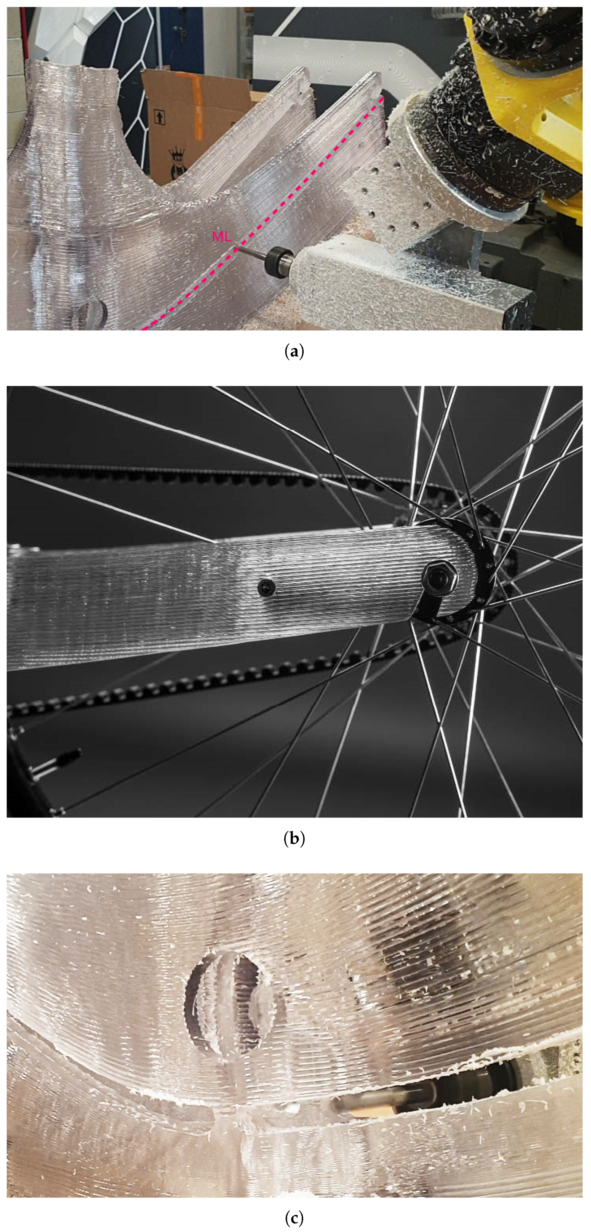
Figure 9.
(a) Close-up of the milling job of New01Bike CLH prototype performed with Fanuc M-710iC 45M robot, in a photo dated 19th of April, 2022. (b) Detail of chainstay of prototype D15V12 dated 20th of April, 2022 of New01Bike: in this case, the milling operation cannot but cut through the layers of the frame to shape it according to the desired proportions and divide it from its support. (c) Close-up of New01Bike ALH version, in a photo dated 22th of July, 2022. In this case, the milling operation severs the frame from the support following the layer orientation of the additive part, without breaking the layer.
Figure 9.
(a) Close-up of the milling job of New01Bike CLH prototype performed with Fanuc M-710iC 45M robot, in a photo dated 19th of April, 2022. (b) Detail of chainstay of prototype D15V12 dated 20th of April, 2022 of New01Bike: in this case, the milling operation cannot but cut through the layers of the frame to shape it according to the desired proportions and divide it from its support. (c) Close-up of New01Bike ALH version, in a photo dated 22th of July, 2022. In this case, the milling operation severs the frame from the support following the layer orientation of the additive part, without breaking the layer.
The first reason is that the feasibility of the printing job is always constrained by the offset of the mold’s surface in the Z direction, which may be followed by the Fanuc R-2000iC 210L robot until G1 continuity (or tangent continuity) of the surface breaks (see Figure 10(a)). In fact, the reachability of the last layers of the seat post is drastically reduced after 490 mm, since the toolpath is following the mold surface. This is indeed a limit of CLH slicing: in fact, to a smaller and smaller radius of the offset 3D arc, corresponds a steeper and steeper acceleration ramp to follow it with the EOAT.
The second reason is connected to the usability of the frame: it is necessary to maintain some key proportions and distances (mainly between the sides of the ideal parallelogram enclosed within the bottom bracket, seat post, head tube and rear dropout vertices), which may be preserved only if the milling operation cuts intra-layer, severing the print from its support (see Figure 9 for a reference of the milling line in CLH mode). Milling through multiple layers at once without following the flow direction of the extrusion exposes the print to very uneven resilience to mechanical shocks. Recycled pellet extrusion produces thick chips with more variation in morphology, occasional voids, debris and possibly imperfect inter-bead fusion at the microscopic scale: cutting within a layer can concentrate stresses at these micro-voids, which in turn may propagate cracks more easily. This means the frame is more exposed to brittle rupture. In contrast, cutting along the primary flow orientation tends to distribute stresses along more continuous material paths, reducing fractures.
These two issues reduce the possibilities of adapting the frame to other body proportions unless, instead of employing offset, the slicing is performed using ALH and tweened surfaces. Employing four main generative surfaces, three tweened surfaces (see Figure 10(b))—from bottom to top of respectively 45, 65 and 140 layers—make robot reachability entirely adaptable to the specific design of the ruled surface section and allow to mill the model following the layer direction. Lowest and highest LH are: 0.6 to 2 mm for the bottom tween group, 0.6 to 2.4 mm for the medium, and 1.2 to 2.1 mm for the top one, producing a maximum-to-minimum layer height ratio (LHR) of 4. The frame weight dropped half a kilogram, to 7.4 kg, as a direct consequence of this slicing strategy.
The second version of New01Bike, manufactured with ALH slicing, was displayed (Figure 11(a)) at the Design Museum in Munich (Pinakothek der Moderne) as the most recent among a selection of 70 bicycles spanning from the late 1800s to 2022 [43] and patented (Figure 11(b), Figure 11(c) and Figure 11(d)) in conjunction with the exhibition.
3.2. Amarcord
Integrating various technologies—motion tracking, CNC-steel bending, augmented reality (AR) assisted assembly and LFAM 3DP—Amarcord is a multidisciplinary artistic project in the form of a sculpture made of steel and PC, weighting about 76 kg and measuring respectively 2000 x 1690 x 1900 mm in length, width and height.
The project started officially in May 2022 with the first LHR experiments breaking the former New01Bike results. It then took a sprint in January 2023 with the project management of Pierpaolo Ruttico, when all the partner companies were officially on-boarded, and was designed, fabricated and coordinated by Federico Bordoni, with the scope of exploring ALH in the context of adaptive shell structures.
Alongside the LATI-D version of New01Bike—Amarcord was presented at Bologna MECSPE in April 2023, an international reference fair for the manufacturing industry, to showcase the immense potential of large-scale LFAM extrusion with recycled PC and precisely to record the database of ALH changes explored in INDEXLAB using LATI-A, probing the limits of the EOAT technology while extruding with challenging inclinations with respect to the print bed.
In fact, if New01Bike solved the seat post toolpath continuity issues through ALH slicing, it is still not clear until what extent the extrusion quality tested with specific RPM-to-LH correlations may be retained with a certain angle of extrusion. The maximum extrusion angle with respect to the print bed experimented in New01Bike was 44 °, and corresponded to the maximum concavity of the first layer of conformal print on the wooden mold. Extrusion failures may be occurring while using steeper inclinations of the EOAT.
Figure 12.
Amarcord on display at MECSPE 2023, in a photo dated 31th of March, 2023
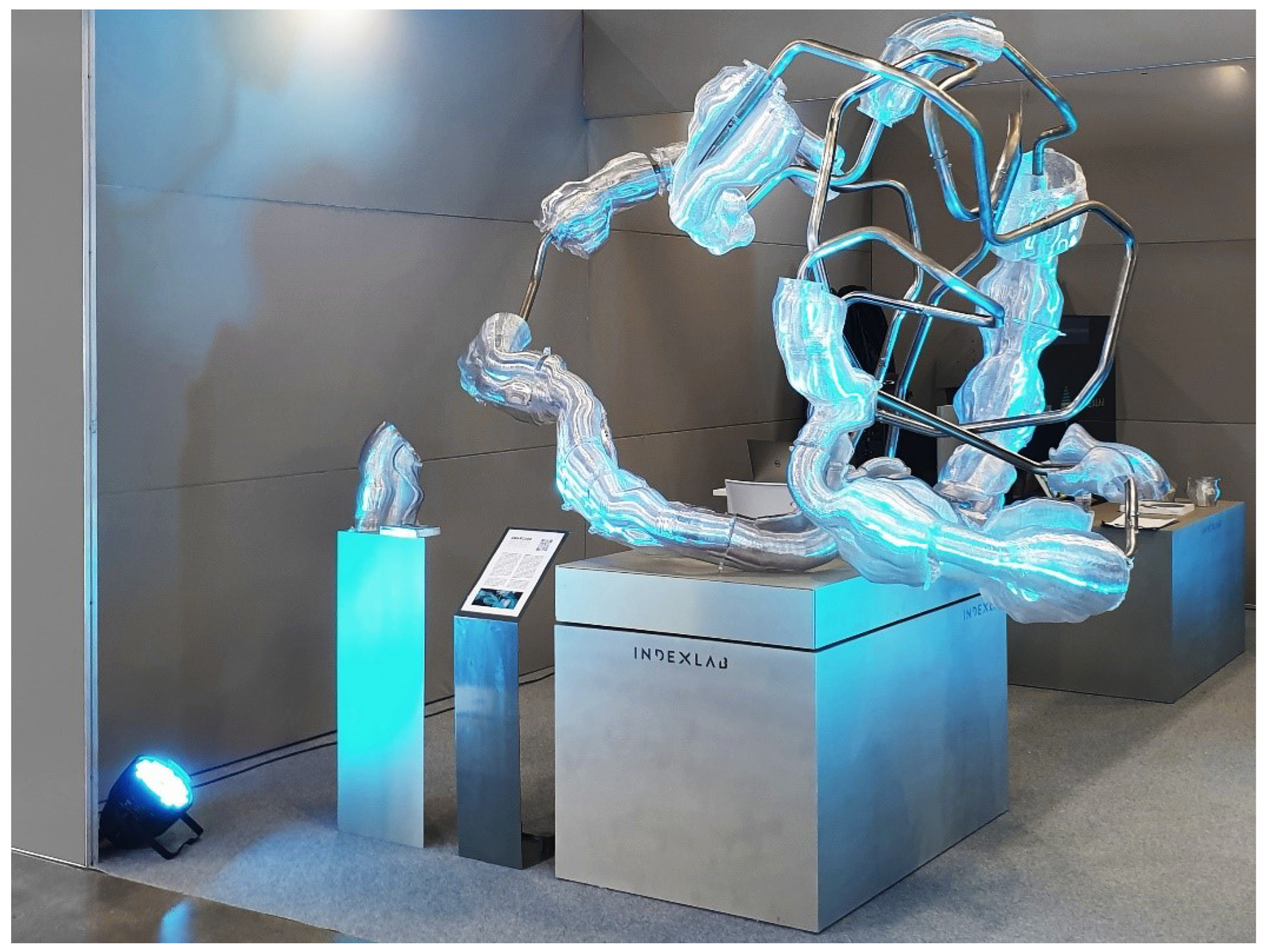
The concept behind Amarcord is to capture the spontaneity and the immediacy of dance with the use of adaptive geometries. The systematic variation of movement is represented as an enlarging and shrinking landscape of PC hollow-core volumes attached along a bent steel tube, sectioned and riveted at the ends to conform to a specific 3D trajectory in space. Amarcord is structured as an archive of possibilities, of trial and errors, describing the effort in fine-tuning ALH ranges—employing arc-based planar slicing—to a complex rail curve: can a 3DP shell follow bends going from 23 to 89 ° and be press-fit to a uniform line-arc rail with minimum tolerances (under 2 mm)?
The first experiments with a higher LHR were undertaken extruding with LATI-C, employing a toolpath resembling a long fin-like shell, measuring up to 750 mm in length. In these experiments, the shell’s minimum and maximum LH are concentrated at the ends, the maximum LH is fixed to 2 mm, and the minimum LH decreases with every printed fin, up to 0.4 mm. From the first ALH experiments (Figure 13(a)), featuring two simple spikes and no TB in correspondence with the minimum LH portion, the section evolves to a TB wrapping around the tube-fitting opening.
Divided by a canyon becoming narrower and more tortuous with every design iteration, both in plan and section, the shell volume of the fin becomes a bent parametric wall with creases to horizontally and vertically constrain the TB and minimize the VSR.
The two most promising experiments were D5V13 (Figure 13(d) and D6V18 (Figure 13(h)) section prototypes, both extruded at a deposition speed of 40 mm/s with a constant layer width of 8 mm. While in all the other experiments some evidences of either warping or layer collapse were noticeable, in these two cases neither one visibly occurred.
In the first one (Figure 13(d), the section length was 600 mm, the VSR was 15.5, the distance between specular parts of the toolpath in the section midpoint was 34 mm, and the total height of the TB 151 mm. The slicing of the piece was performed using 150 tweened layers, the angle difference between the first and the last extruded layers was 11.5 °, the minimum and maximum LH were 0.42 mm and 1.38 mm respectively, the LHR was 2.85, the minimum and maximum RPM were 44 and 199 respectively.
In the second one (Figure 13(h), the section length was 378 mm, the VSR was 10.11, the distance between specular parts of the toolpath in the section midpoint is 25 mm, and the total height of the TB 361 mm. The slicing of the piece was performed using 300 tweened layers, the angle difference between the first and the last extruded layers was 43 °, the minimum and maximum LH were 0.70 mm and 1.84 mm respectively, the LHR was 2.62, the minimum and maximum RPM were 86.9 and 300 respectively.
The first one demonstrates to accomplish a higher LHR—with a minimum LH smaller than New01Bike—with a longer and larger section length compared to the second one. Nonetheless, it fails to provide: any decisive insights on the TB, provided the small height compared to section length, or any hints concerning extrusion quality at higher EOAT inclinations. The second one shows a higher maximum LH without collapsing with a slightly higher and thinner TB, and steeper maximum EOAT’s angle of extrusion.
Once again, as in the empirical experiments of New01Bike, this suggests that lowering VSR (15.5 vs 10.11) while maintaining a higher TB may provide a more reliable configuration for maintaining structural integrity and extrusion quality when in the context of high LH in inclination-intensive prints. It is also interesting to notice that, even if the TB is thinner, the more the geometry "curls" on itself to incorporate the tube-fitting opening (thus minimizing the VSR), the more heat retention is gained. This somehow hints at the fact that a hollow-core ring section may have larger heat retention capabilities, because it is benefiting from more TBs at once. This consideration is key to understand the geometrical development of the 3DP PC clouds of Amarcord, where the section curl on the tube was taken as pivotal parameter for the volumetric generation of each sweep.
The Grasshopper3D algorithm structuring Amarcord is composed of multiple parts, and covers all the process: interpretation and parsing of motion data, steel tube trajectory planning with post-processing for machine bending, PC section and sweeps creation, data visualization to understand basic fabrication feasibility and constraints, extraction and selection of sweep portions for AM, slicing, program-assembly, collision check, post-processing for robotic fabrication, ALH basic database creation. The definition uses Hops Components [44] to separate in clusters and run all these different parts asynchronously. Employing parallel processing, Hops offloads tasks demanding high computing power to a local rhino.compute sever instance and solves them in separate processes, returning the outputs to the current document.
Amarcord’s steel tube rail loosely follows the path of two dancers’ limbs (Figure 14(a)), as they are captured in an instant of a .FBX point-cloud animation (Figure 14(b)) that traces their freeform trajectories in space. 17 pieces of steel tube are connected to form a 2300 mm-long complex rail, made of natural Bezier-like trajectories. A Grasshopper3D algorithm parses the point-cloud, converts the trajectories to lines and arcs (Figure 14(c)), and then to G-code instructions for a CNC tube-bending machine: it sections the tube in pieces that measure a maximum of 2500 mm to prevent collisions with the surroundings during machine bending (Figure 14(d)).
Every piece of tube is of a uniform diameter of 35 mm and 2 mm thickness, and features a rotation about the adjacent one’s axis that is described with polar angles and a list of bending angles. The complexity of assembling the whole rail and rotating each tube segment around the preceding one to achieve the final 3D configuration (Figure 14(e)) is solved by using Microsoft HoloLens 2 and employing the Grasshopper3D plugin Fologram [45] to visualize the 3D model and guide the reconstruction of the actual geometry in space.
Each one of the 6 LATI-A 3DP clouds is developed as a sweep, selecting a different portion (Figure 14(f)) of the bent tube as rail, with lengths ranging from 500 to 2075 mm, and a number of C-shaped silhouettes—ranging from a minimum of 7 to a maximum of 28, with each one varying in proportions and featuring a consequential rotation about the preceding—as sections. After toolpath checking (Figure 14(g)) and file post-processing, they are printed in ALH (Figure 14(h)) with Fanuc R-2000iC 210L robot in INDEXLAB.
The pipe portions are parametrically divided to allow for a maximum of 5 sections to be generated from each portion in order to produce a part of a possible sweep. Sections are created starting from a bounding circle: indeed, having dispatched line-like and arc-like portions of the pipe rail, to each one is assigned a maximum bounding circle radius where the section is inscribed, making sure sweeping through it never generates a self-intersecting volume. This radius—which goes from a minimum of 80 to a maximum of 218 mm, in the case of the largest sections—is then lowered down by a safety factor of 10 mm to produce the maximum section length. These maximum lengths can later be tweaked to allow for some variation on the theme and the generation of more aesthetically pleasing formal possibilities with respect to selected arcs. Each sweep begins and ends with a standard, un-creased, section of a maximum length of either 50 or 60 mm, in a line-like part of the tube, ideally closing the volume of each PC cloud with a coherently smaller edge.
Apart from allowing great formal variety with a set of simple parametric rules, the chosen section topology (Figure 15) was selected because of an aesthetic reason, related to the creation of variation in the different cloud-form volumes through sweeping, and two functional reasons: in order to press-fit the volumes to the tube, and to further experiment what happens to heat retention with TBs forming hollow-core ring sections. To address these last two issues, the section features, respectively, a C-shaped portion which is to be press-fit to the tube, and a cantilever portion of varying configuration.
The C-shaped portion is an arc-like pipe sub-curve whose angle domain—comprised between 160 and 170 °—coincides with the opening angle to fit the sweep around the pipe. The continuation of the arc with a tangential line in the section plane culminates with the main spike of the section, which develops the main opening crease in each swept volume.
The cantilever portion is divided in: a first chunk in the form of another arc, tangential to the C-shaped portion and whose angle domain of 72 °—the same for all the sections—coincides with the section curl, the twist of the section around the pipe; a second chunk interpolates a set of crease points, or spikes, pseudo-randomly displaced with a fixed displacement factor from the section’s bounding circle and employing 15 vectors that equally divide the entirety of the opening angle. This generates an interpolated third-degree curve of crease points that tangentially connects the first chunk of the cantilever with the main opening crease.
To conclude, visualizing the volumes actually swept through these sections, three main TBs are respectively created: one chimney-like cavity which resembles a tortuous multi-segmented pipe of varying diameter (TB 1) and a second larger cavity that culminates with a canyon-like crease (TB 2), which are divided by the pipe-fitting opening (TB 3). This TB, while still being part of the perimeter, is facing the exterior of the swept volume.
The 3DP process began the 20th of March, 2023 and finished on the 25th of March, 2023. To produce the robot programs for AM, each sweep is sliced following the lines and arcs of the rail, sectioning with perpendicular frames distanced 2 mm one from the other with respect to the center of the tube. As this guarantees that every layer’s slicing plane is equally distanced from the consequent one it also mandates that, in correspondence with the arc portion of the rail, LH contraction and expansion will be larger in the part of the sweep section which is farthest from the pipe, and proportionally increasing with the bounding circle of the section.
By showing all the transitions between line-like—corresponding to CLH slicing—and arc-like portions of the tube—corresponding to ALH slicing to cover the angle of each arc—Amarcord is also openly drawing upon the corduroy aesthetics of 3DP. The swept geometries are presenting all the marks of these transitions in the AM extrusion process as if their were surface features, and thus showing the range of angles they did or didn’t successfully bridge. As in New01Bike, this is indeed a major point towards promoting this sort of aesthetics, given that the EOAT extrusion flow is able to follow the geometry’s iso-curves from 0 to 89 ° without resulting in any visible flow instability or extrusion inconsistencies.
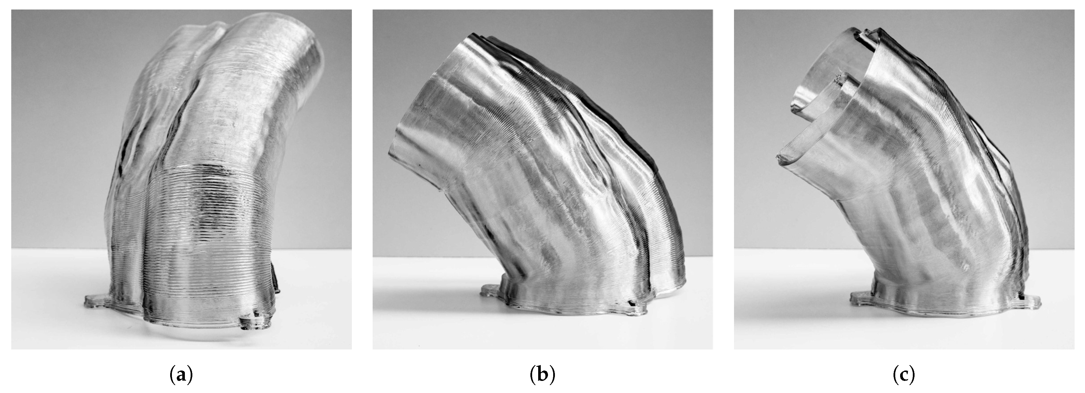
Figure 16.
Sweep 4;0, a PC shell bridging a 43 ° bend on the rail tube employing 2 LH variations, in three photos dated 30th of March, 2023. Even if the PC shell’s transparency may blend the layer perception and nuance some height differences, the transitions between CLH and ALH are still very clear.
Figure 16.
Sweep 4;0, a PC shell bridging a 43 ° bend on the rail tube employing 2 LH variations, in three photos dated 30th of March, 2023. Even if the PC shell’s transparency may blend the layer perception and nuance some height differences, the transitions between CLH and ALH are still very clear.
Motion path is simulated in order to avoid the EOAT impacting against the print bed or with the print itself. Each sweep portion has to be divided into smaller pieces to allow each print to be lasting a maximum of 2 hours (the longest print is approximately 95 min) with a an average deposition speed of 50 mm/s, and to feature a maximum of 3 LH changes. This rule of thumb ensures, given the LFAM printing tolerances, the clouds are not too difficult to press-fit to the rail after the fabrication process has finished and inter-layer adhesion is optimal.
Figure 17.
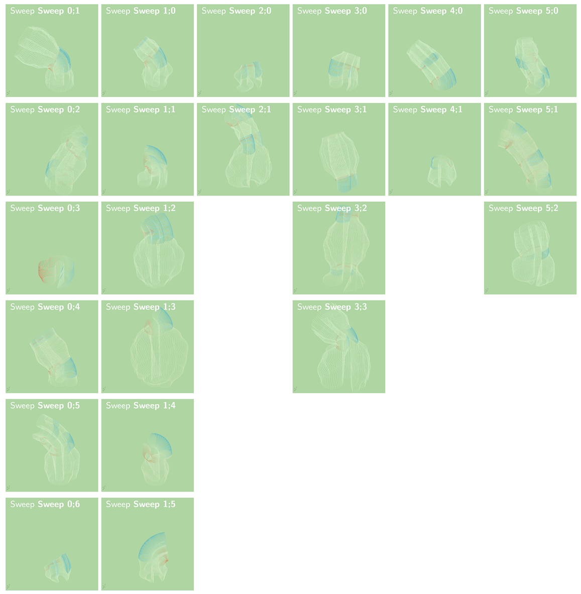
Amarcord’s full view representing, using a tone from red to blue, minimum and maximum LH per sweep portion, in a Rhinoceros screenshot.
Figure 17.
Amarcord’s full view representing, using a tone from red to blue, minimum and maximum LH per sweep portion, in a Rhinoceros screenshot.
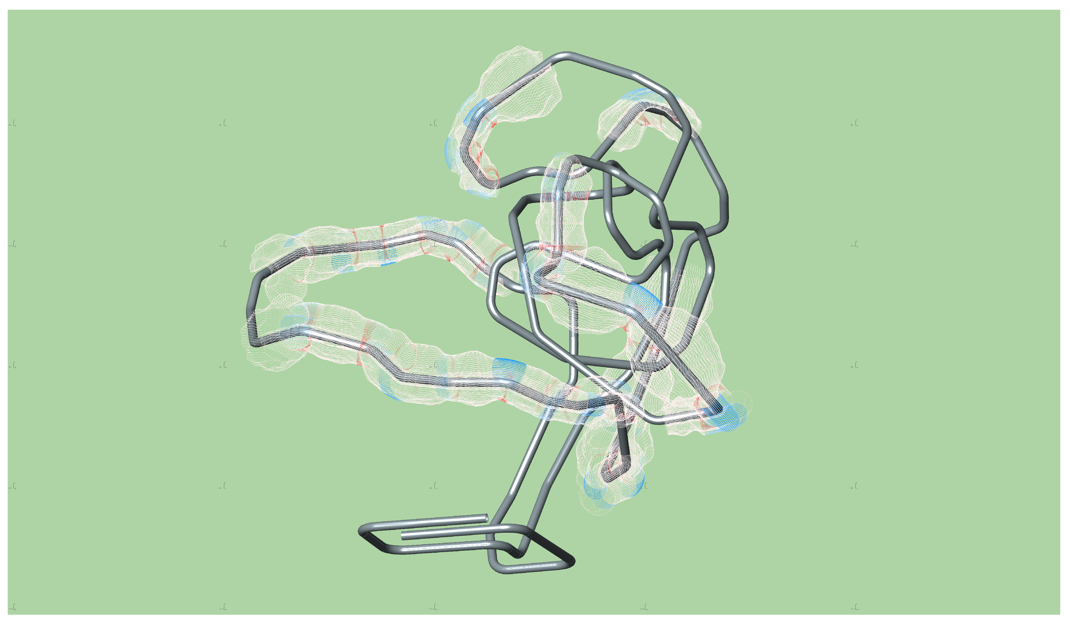

Table 3.
On the top, plot of 3DP data for Amarcord. Note that Sweep 0;0 and Sweep 4;3 are missing from the chart because they were not printed. On the bottom, multiple close-ups representing, using a tone from red to blue, minimum and maximum LH per sweep portion.
Table 3.
On the top, plot of 3DP data for Amarcord. Note that Sweep 0;0 and Sweep 4;3 are missing from the chart because they were not printed. On the bottom, multiple close-ups representing, using a tone from red to blue, minimum and maximum LH per sweep portion.
| Print Time (min): | Total Layers: | Max LH (mm): | Min LH (mm): | Max LHR: | LH Variations: | Degrees Covered (°): | TB Height (mm): | Total VSR: | |
|---|---|---|---|---|---|---|---|---|---|
| Sweep 0;1 | 65 | 224 | 3.8 | 0.1 | 26.7 | 1 | 59 | 448 | 30.5 |
| Sweep 0;2 | 61 | 234 | 4.3 | 0.1 | >36 | 2 | 54, 28 | 468 | 25 |
| Sweep 0;3 | 20 | 73 | 2 | 2 | 1 | 0 | None | 146 | 26.7 |
| Sweep 0;4 | 41 | 170 | 4.9 | 0.1 | 28 | 2 | 22, 40 | 340 | 22.5 |
| Sweep 0;5 | 58 | 234 | 4.6 | 0.2 | 24.2 | 2 | 22, 32 | 468 | 23.9 |
| Sweep 0;6 | 15 | 72 | 3.9 | 0.1 | 25.8 | 1 | 51 | 142 | 18.2 |
| Sweep 1;0 | 40 | 175 | 3.9 | 0.2 | 17.4 | 2 | 10, 48 | 349.9 | 20.4 |
| Sweep 1;1 | 29 | 127 | 3.9 | 0.2 | 19.4 | 1 | 76 | 253.9 | 19.3 |
| Sweep 1;2 | 72 | 230 | 3.8 | 0.2 | 21 | 1 | 81 | 459.9 | 33.1 |
| Sweep 1;3 | 86 | 239 | 4.9 | 0.2 | 29.2 | 1 | 50 | 477.9 | 38.9 |
| Sweep 1;4 | 33 | 138 | 4.9 | 0.2 | 20.8 | 1 | 69 | 275.9 | 22 |
| Sweep 1;5 | 28 | 129 | 4.7 | 0.2 | 25.9 | 1 | 86 | 255.9 | 19.3 |
| Sweep 2;0 | 17 | 78 | 3.8 | 0.2 | 25.2 | 1 | 44 | 156.1 | 17.2 |
| Sweep 2;1 | 77 | 275 | 4.4 | 0.2 | 20.3 | 2 | 55, 46 | 548.4 | 28.9 |
| Sweep 3;0 | 25 | 112 | 4.4 | 0.2 | 19.7 | 1 | 38 | 224.1 | 19.8 |
| Sweep 3;1 | 47 | 165 | 4.5 | 0.2 | 26.1 | 1 | 35 | 330.1 | 29 |
| Sweep 3;2 | 75 | 248 | 4.9 | 0.1 | >36 | 2 | 35, 19 | 496.2 | 31 |
| Sweep 3;3 | 95 | 280 | 3.9 | 0.2 | 22.4 | 1 | 45 | 560.2 | 36.6 |
| Sweep 4;0 | 33 | 163 | 3.9 | 0.2 | 23.9 | 3 | 22, 45 | 326.3 | 18.2 |
| Sweep 4;1 | 19 | 87 | 3.9 | 0.2 | 19.4 | 1 | 10 | 172.2 | 20.7 |
| Sweep 5;0 | 40 | 172 | 3.8 | 0.1 | 30 | 2 | 28, 32 | 344 | 21.9 |
| Sweep 5;1 | 51 | 216 | 5.2 | 0.2 | 28.5 | 3 | 32, 22, 28 | 431.9 | 23.3 |
| Sweep 5;2 | 59 | 212 | 3.8 | 0.2 | 20 | 1 | 22 | 422 | 28.3 |
The experimented LH go from 0.1 to 5.2 mm, with a general tendency to produce under-extrusion if thinner than 0.15 mm, and layer collapse over 4.3 mm without operating additional cooling devices. The steepest LHR measured with the caliper that was successfully printed in Amarcord—without producing extrusion inconsistencies or layer collapse—is 1 to 26.
It is difficult to calculate the TBs’ contribution to the heat retention capabilities of the pieces, especially given that TB 1 and TB 2 are placed, with every consequential rotation of the sections creating each sweep, sometimes in correspondence with minimum and sometimes with maximum LH. Nonetheless, since experimental observations suggest that edges lose heat faster because they are more exposed to cooling gradients, the fact that TB 3 is conveniently placed near the sweep section centroid—shaped as inward and not as outward appendix—decreased the effect of warping on the piece, creating heat retention.
Employing the same material of New01Bike, in Amarcord LHRs from 4 to 6 times larger were effectively printed, with minimum LHs from 3 to 4 times lower, and most importantly without warping in correspondence with the pipe-fitting opening. Minor warping happened to the first layers attached to the print bed, but yielded no substantial over-tolerance displacements or distortions in correspondence with TB 3.
TB 3 is always placed near the centroid of each section between TB 1 and TB 2, where LH is varying less: normally a couple of decimals around 2 mm. Nonetheless, TB 3 is distanced almost half of the section length from the main border of each sweep and still partially exposed to the outside. As it happened with the chainstay in the first CLH planar trials of New01Bike—also printed with a 2 mm LH—peripheral portions of the toolpath exposed to the outside should have warped more.
3.3. OneLineTwoCoils
OneLineTwoCoils is a rolling chair designed by Ron Arad Associates and engineered by INDEXLAB, whose volume is designed to be produced through LFAM. While OneLineTwoCoils received its initial presentation at a privately held event at Rossana Orlandi’s gallery in Milan in November 2023, the project started officially about a year earlier, with the R&D and form-development phase commencing in May 2022 and the first print tests in INDEXLAB from July 2022. OneLineTwoCoils weights about 36 kg and measures respectively 1100 x 630 x 790 mm in length, width and height.
After the experiences of New01Bike and Amarcord, OneLineTwoCoils ’s exploration occurs at a pivotal moment in the evolution of form-engineering practices at Gimac Int. S.r.l. and eXgineering SA, as well as in the development of vertically integrated DfAM projects at INDEXLAB. In fact, since it is characterized by continuous, highly articulated 3D curvature, variable cross-sections and the presence of undercuts, OneLineTwoCoils’s shape cannot be realized through conventional injection molding without segmentation, multi-part tooling, and consequent mold-lines or assembly.
Figure 18.
Teaser photo of OneLineTwoCoils dated 27th of June, 2023
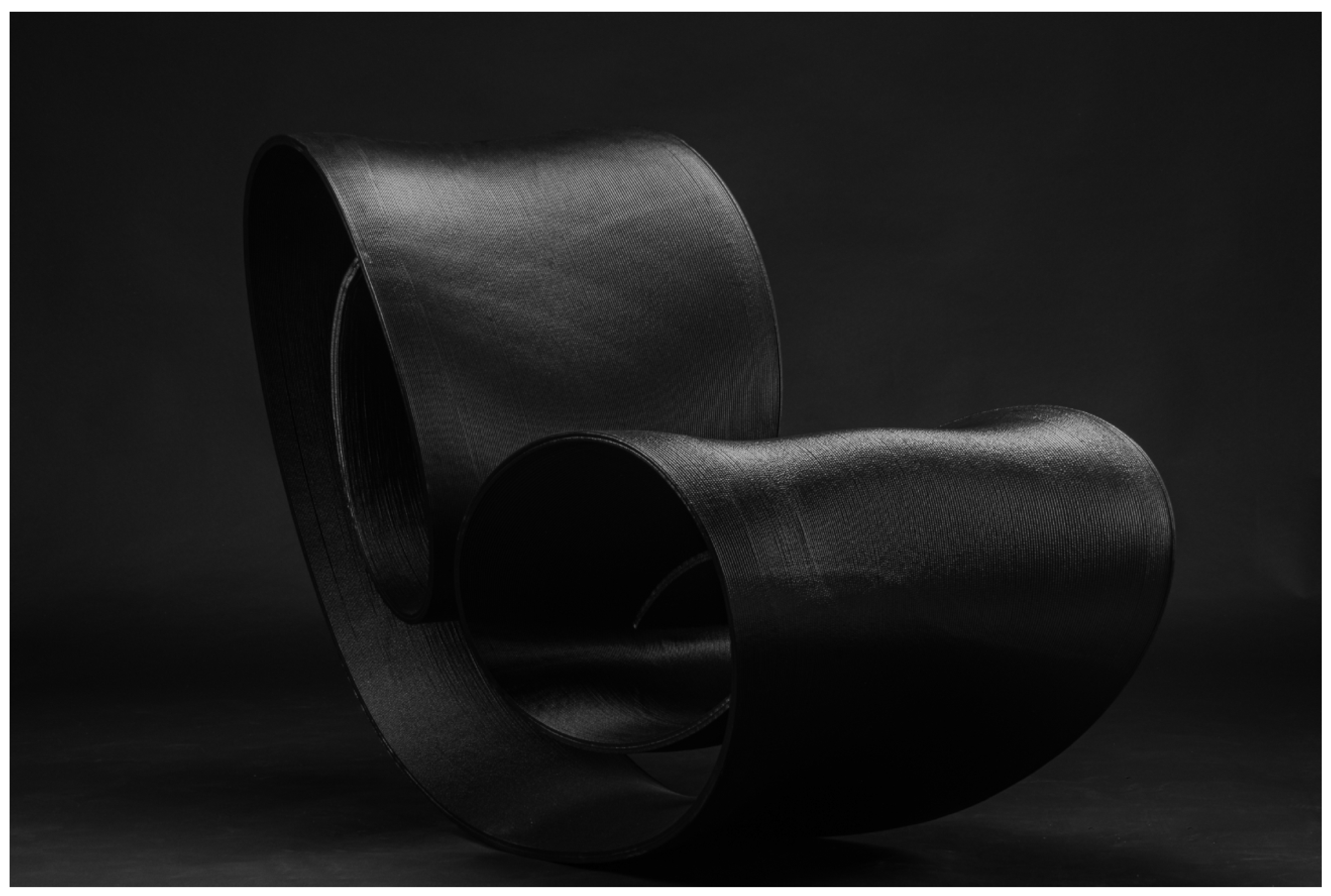
Instead, with the use of a custom 3DP mold, the chair may be printed with a LFAM process, leveraging ALH and the degrees of freedom of an articulated robot. With a DfAM approach, every layer of the chair is featuring a compression-expansion-compression cycle of LH which creates—with every subsequent layer—a functional part of the chair (expansion in the seat and the backrest portions, compression both at the interface with the ground and in the curls).
If every layer is a complex (non-ruled) G2-continuous 3D curve, smoothly changing its orientation and extrusion RPM values point-to-point to guarantee both the adherence of the next layer and the shrinking and enlarging of the chair’s volume, the chair may be printed as one monocoque piece without necessitating accessory surface treatments, part assembly or complex de-molding. In this sense, the case of OneLineTwoCoils is at the apex of the shift partially started with New01Bike, where the creative process generates form directly as a consequence of the technology’s process parameters.
Form is only conceived as a result of the interdependence between the trajectories of the 6dof robot in space and the extrusions performed with the EOAT. The iso curve-based slicing of the 3D model yields the same layer-to-layer distances, but is coordinated point-to-point to make sure the chair can be as large as the maximum LH allows without layer collapse, and as slim as the minimum LH which can be printed without under-extrusion.
Through an intense sparring to improve surface development for 3DP—undertook with the help of Marcus Hirst of Ron Arad Associates—and a custom Grasshopper3D algorithm developed by INDEXLAB, the first tests (Figure 19) to 3DP half of the chair, were performed with LATI-C on a flat print bed. These tests were necessary to: calibrate ALH in the context of non-ruled surface-based slicing—allowing the touching of the TB ends with the increase of LH on a non-planar toolpath—and prevent the EOAT collisions with the already 3DP part.
Drawing from New01Bike’s experience, as the geometry becomes increasingly constrained by the risk of warping, this constraint can be mitigated by redesigning the heat-retention characteristics of the PC shell: acting on the shape of the print bed, lowering VSR with the incorporation of TBs. In the case of OneLineTwoCoils, these two actions are already embedded in the original design of the chair, but proved both challenging to fit perfectly to its geometry.
Remodeling the print bed from the ideal flat plane is necessary to print the entire chair. Stressing the limits of the ALH manufacturing process, the coiled development of the chair is tuned directly to the EOAT extrusion parameters, which—summed up layer after layer starting from the mold—dictate the overall silhouette of the piece.
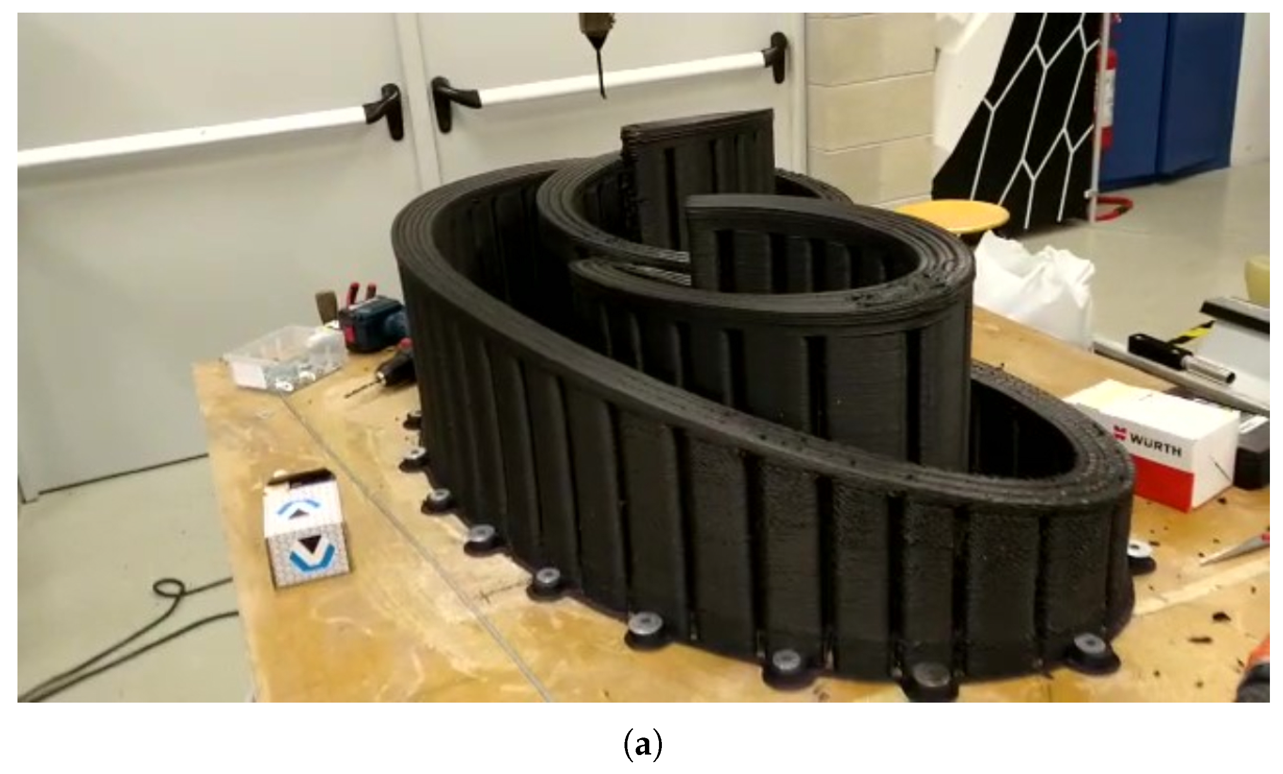
In fact, starting the print on the chair’s side, with a one-turn brim and the touching perimeter on a custom ABS mold (Figure 21), the volume builds up following the normal directions—from every layer’s minimum LH, which is the end of one of the two curls, towards maximum LH, corresponding to seat and backrest, and back to the ending curl—until it reaches the frontal symmetry axis at maximum LH, then continues until the ending cap in a mirrored fashion.
Figure 20.
Photos dated 27th of June, 2023 documenting (a) side, (b) front, and (c) back of OneLineTwoCoils’s first version, successfully printed the 07th of November, 2022 in INDEXLAB using LATI-C. The print was performed at 100 mm/s deposition speed, with 8 mm LW, 0.66 to 3.19 LH (4.83 LHR), with a VSR of 1.10 and RPMs going from 170 to 1214.
Figure 20.
Photos dated 27th of June, 2023 documenting (a) side, (b) front, and (c) back of OneLineTwoCoils’s first version, successfully printed the 07th of November, 2022 in INDEXLAB using LATI-C. The print was performed at 100 mm/s deposition speed, with 8 mm LW, 0.66 to 3.19 LH (4.83 LHR), with a VSR of 1.10 and RPMs going from 170 to 1214.
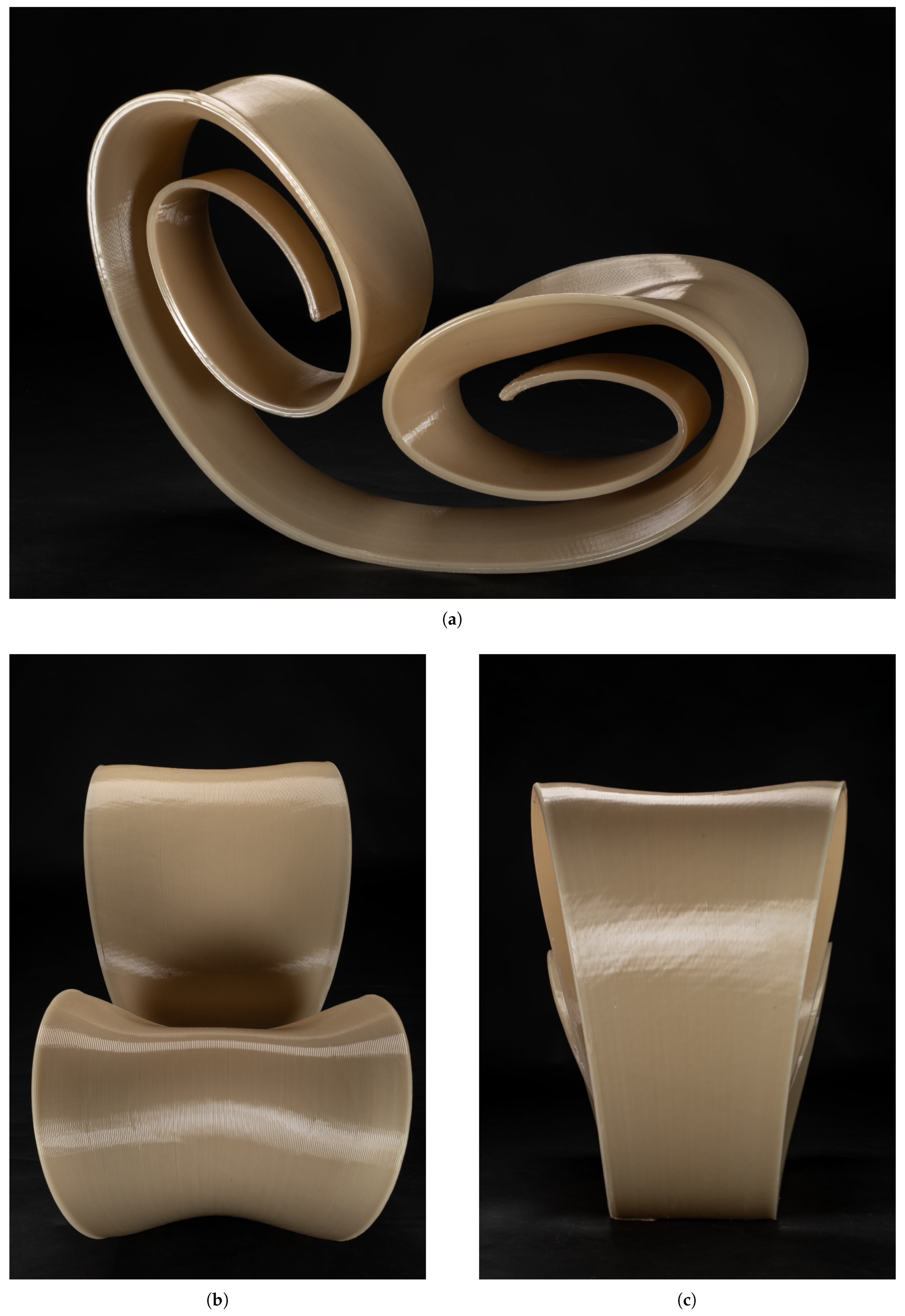
Figure 21.
(a) OneLineTwoCoils’s 3DP ABS mould in INDEXLAB, still from a video dated 25th of October, 2022
Figure 21.
(a) OneLineTwoCoils’s 3DP ABS mould in INDEXLAB, still from a video dated 25th of October, 2022
OneLineTwoCoils’s VSR is 1.10, a value that is very low compared to any value of VSR hence experimented. Much like New01Bike’s down tube, which forms an air socket in the frame with a section that is determined by the incremental separation and then re-joining of the double perimeter extrusion—OneLineTwoCoils’s TB is shaped as the void comprised between the inner and outer surfaces of the rolling chair. The TB is as large as the peak of maximum distance between the perimeters (107 mm), and as high as the peak of the seat portion, the width of the chair (around 600 mm). Its vertical caps are the first and the last group of perimeter layers, which have to fully touch to guarantee the structural rigidity of the piece. Its horizontal caps are the endings of the two curls, where the two perimeters touch.
After the first prototyping phase, carried on employing LATI-C (Figure 20), OneLineTwoCoils has been printed employing LATI-D: a reinforced recycled PC, a blend of PC pellets mixed with 30% carbon fibers which enhances stiffness, distributes heat and stresses, and reduces the susceptibility to brittle failure under shock.
4. Discussion and Future Directions
From the results of the New01Bike, Amarcord and OneLineTwoCoils projects, this work shows a design-oriented approach which may organically encourage reproducibility in LFAM using recycled pellets while also exposing some inherent limitations and open questions.
4.1. Geometry and Process Co-Evolution
The first limitation is about the possibility of changing design with manufacturing constraints. Minimizing the cooling stresses iteratively, by reducing areas that might cool unevenly in the design phase, or developing AM volumes as infill-free PC shells, is only allowed in vertically-integrated R&D phases, where consensus exists that geometric fine-tuning is permitted, provided it enhances overall design quality.
An example of this is particularly evident for New01Bike, where the opportunity of re-modeling the print bed to try to solve vertical warping created the excuse for further studying a formally, design-oriented, solution to a physical constraint induced by the material. Conformal printing on a surface whose curvature normals roughly follow the warping direction proved to be more useful than trying to retain the print on a flat print bed.
This strategy was deliberately adopted both because this iteration between design and manufacturing constraints was encouraged by the client, and also because enclosing a large portion of the laboratory within a thermostatic chamber would have been impractical (particularly given the constant movement of students in and out of the space).
Using conformal printing means surface-based slicing—and overall more computational effort on the software side to calculate the EOAT’s trajectory and slicing efficiency—will have to be deployed. At the same time, at the beginning of the 3DP process, less manual intervention is needed to secure the brim and the first layers to the print bed: a process that oftentimes is carried on directly by the machine operator, and frequently at the expense of human-machine safety interactions and the overall process reproducibility.
Constraining part geometry is often difficult to implement without a more extensive, bottom-up redesign, which must always be validated and strategically assessed by the client. In these cases, an established trust relationship provided a basis for a larger investigation into AM practices with recycled feedstock that was very focused on the co-evolution of geometry and process.
4.2. Quantifying Warping Mitigation
Assessing the extent until which hollow-core 3DP, the height and proportions of the TB, and the low VSR will positively impact heat retention, producing a mitigation of warping without inducing a collapse of the layer, remains an intricate multi-factorial challenge that requires extensive empirical testing and a matrix capable of isolating these interdependent variables.
Warping is the cause of very uneven and unpredictable distortions difficult to forecast even in the most regular 3DP volume—and all the mentioned projects are geometrically complex—but the effect of these three factors on the possible collapse of the layer are still noticeable in an empirical way.
From the experience of New01Bike, it is clear that in regions where the two shell perimeters are in direct contact heat dissipation is more rapid and warping happens more. When the two perimeters are separated by a TB, (i.e. engineering the model perimeter, doubling it and enclosing voids within, lowering the VSR) this concurs in establishing a primary direction of heat retention, and the layers tend to collapse with lower layer times than their non-hollow counterparts.
Drawing on Amarcord, it can be inferred that there might be a width threshold above which the "wall-like", longitudinal TB may be less effective in retaining heat. Nonetheless, if it is strategically placed near the centroid of the 3D volume, if it features a ring-like shape curling on itself, if it is shaped as an inward—rather than outward—appendix, it maintains and even multiplies its heat retention capabilities. High LHRs are achievable as low LHs feature less under-extrusions and less warping, and high LHs tend to collapse more, with lower layer times.
OneLineTwoCoils, in this case, provided a synthesis consistent with these assumptions, exhibiting similar thermal retention behavior and deformation patterns under comparable conditions.
4.3. Eliminating Finishing to Emphasize Isocurves and ALH
Is it possible to eliminate costly and additional surface customizations if the surface finish is exposing the step effect of every layer change in height and width? Is this mechanistic aesthetic exalting or stripping away important parts of how a product should look and feel?
While no obvious answer to these questions is given in the article, it is arguable that without the finishing one could embrace a more organic view of the layer, from simple engineering block to something that may offer visual richness and sensory presence. The geometry of the chosen slicing process and the extrusion quality (particularly with ALH) impacts both the mechanical resistance and the visual identity of the piece, giving a shape to the volume’s generative surfaces and the manufacturing process.
Surface polishing was tested on some of the prototypes of New01Bike and OneLineTwoCoils (Figure 22) and yielded excellent results thanks to the properties of the selected polymeric compound. Nevertheless, it was consistently chosen to leave the layers untreated, framing the “corduroy” texture as a deliberate aesthetic adoption of Ron Arad Associates. This decision was taken with the shared objective to achieve a minimal and economically efficient process—–eliminating unnecessary fabrication steps–—and by the client’s acceptance of this approach.
Discovering the correlations between robot, extruder and material it is possible to develop a kind of empirical, stereotomic knowledge. As if crafting solid blocks of extrusion—the building stones—to create the structural walls of the print, like Mayan or Greek stone masters that needed to seize the shape of interface of two stones, this empirical knowledge leads to a deeper understanding of the mutual intertwining between the machine limits of both robot and EOAT.
New01Bike and OneLineTwoCoils are, in this case, the tips of the iceberg, the results of an optimization process aimed at reducing form to the minimum. On the other side, Amarcord and Superframe are the submerged part of the iceberg, a catalog of variations on a theme: all the tests, trials, and failures that are necessary to construct a valuable database of information for the ALH technology.
4.4. The Material Variable and Future Work
The study used post-industrial recyclate sourced from well-characterized and traceable industrial streams, supported by a material advisory partner that helped ensure consistency and quality of inputs. This approach enabled reliable baseline performance assessment using known and controlled material sources, and enables continuous performance enhancement throughout successive design iterations (Figure 23).
Building on this, a next step is to consider true closed-loop recycling, where failed prints are mechanically ground and reused as feedstock for subsequent fabrication. This would enable direct evaluation of material degradation across multiple recycling cycles. In particular, it is important to assess how many reprocessing iterations the material can undergo while maintaining acceptable mechanical and functional performance.
Evidence from related extrusion-based processing provides some support for the feasibility of repeated processing without necessarily causing substantial molecular degradation. For example, microextrusion has been reported to preserve the molecular weight distribution of polymers [46,47], without significant reductions in mean molecular weight. Such findings suggest that, under appropriately controlled processing conditions, extrusion-based reprocessing can be a relatively low-risk approach for high-molecular-weight polymers. This is particularly relevant to the present context, as it indicates that repeated thermal and mechanical processing does not inherently imply severe chain scission; however, the extent to which this can be maintained over multiple recycling cycles remains to be established for the specific materials and processing conditions considered here.
Achieving comparable AM predictive reliability also with closed-loop recycled materials would represent a significant step toward scalable circular material design. Although post-processing additives like stabilizers or compatibilizers may help mitigate degradation [48], such interventions are not always straightforward when the polymer chains have already undergone multiple changes.
Recent studies [49] have focused on evaluating the properties of 3D-printed Polylactide (PLA), derived from recycled food packaging, and ABS sourced from car dashboards, for the purpose of manufacturing engineering components and compared their performance against that of virgin polymers used in 3DP. Although the thermal properties showed minimal differences between the recycled and virgin materials, the recycling process of PLA, being a biodegradable polymer, resulted in some degree of chain scission, leading to a 33% reduction in both tensile stress and flexural strength, while the recycled ABS when properly processed exhibited no significant change in the mechanical response.
Such an approach would provide a practical framework for understanding the limits and viability of circular AM workflows: modeling and archiving the behavior of the recycled material may help improve the prediction of structural deformations under varying conditions. Leveraging AI-based tools with top-down testing, it would be possible to capture complex, nonlinear behaviors that are difficult to model using traditional analytical approaches.
By integrating data-driven learning with physical insights, the models are expected to achieve higher accuracy and generalization across different scenarios.
5. Patents
The patents that resulted from the work reported in this manuscript are available at:
- Maccagnan, S.; Ruttico, P. Method for Producing Objects. IT IT202100011732A1, November 2021.
- Bordoni, F.; Martins Carabetta, F.; Ruttico, P.; Urso, S.; Maccagnan, S. Frame for Cycles and Motorcycles. EUIPO Registered Community Design 015002682-0001, November 2022.
- Bordoni, F.; Martins Carabetta, F.; Ruttico, P.; Urso, S.; Maccagnan, S. Frame for Cycles and Motorcycles. U.S. Design Patent D1,068,565 S1, April 2025.
Author Contributions
Conceptualization, F.B.; Methodology, P.R. and F.B.; Software, F.B.; Validation, P.R. and F.B.; Formal analysis, F.B.; Investigation, P.R. and F.B.; Resources, P.R.; Data curation, F.B.; Writing—original draft, F.B.; Writing—review and editing, P.R., F.B. and S.M.; Visualization, F.B.; Supervision, F.B.; Project administration, P.R.; Funding acquisition, P.R.; All authors have read and agreed to the published version of the manuscript.
Funding
This research was self-financed by the authors and the companies involved. There are no conflicts with third parties.
Institutional Review Board Statement
Not applicable.
Informed Consent Statement
Not applicable.
Data Availability Statement
Other data that support the findings of this study are available on request from the corresponding author.
Acknowledgments
The authors want to thank: Gimac Int. S.r.l. and eXgineering SA for sponsoring this research and for their involvement and commitment at every step of the process, LATI S.p.A. for providing key insights on the material properties, and all the partner companies involved: OMNICAP-GPEM and FASB Linea 2 for Amarcord, and Ron Arad Associates for OneLineTwoCoils. Special Thanks go to their colleagues at INDEXLAB—Francisco Carabetta, Imane El Bakkali, Carlo Beltracchi— and to Gianpiero Bianchi, who all contributed to the technical development and the testing phases behind these projects. Their support and efforts were essential in bringing them to their current state of development. The authors also wish to thank all those who were directly involved in the 3DP projects in INDEXLAB and contributed in various capacities: Zhu Qiulin, Andrea Gentile, Marco Valerio Usai, Meryl Bougo.
Conflicts of Interest
The authors declare no conflicts of interest.
Abbreviations
The following abbreviations are used in this manuscript:
| 3DP | 3D Printing/ 3D Printed |
| 6dof | Six Degrees of Freedom |
| ALH | Adaptive Layer Height |
| AM | Additive Manufacturing |
| AR | Augmented Reality |
| CLH | Constant Layer Height |
| DfAM | Design for Additive Manufacturing |
| EOAT | End-of-Arm Tool |
| LH | Layer Height |
| LHR | Maximum-to-Minimum Layer Height Ratio |
| LW | Layer Width |
| PCR | Post-Consumer Recyclate |
| PIR | Post-Industrial Recyclate |
| LFAM | Large Format Additive Manufacturing |
| R&D | Research and Development |
| RPM | Revolutions Per Minute |
| TB | Thermal Buffer |
| VSR | Volume-to-surface ratio |
References
- Djonyabe Habiba, R.; Malça, C.; Branco, R. Exploring the Potential of Recycled Polymers for 3D Printing Applications: A Review. Materials 2024, 17, 2915. [Google Scholar] [CrossRef] [PubMed]
- Labib, R.; Amin, R.; Hoffman, L.; Labib, R.; Amin, R.; Hoffman, L. Regulatory and Safety Requirement for Use of Recycled Polyethylene in Food and Cosmetic Packaging. In Polyethylene - New Developments and Applications; IntechOpen, 2023. [Google Scholar] [CrossRef]
- European 3D Printing Industry - Size & Analysis. Available online: https://www.mordorintelligence.com/industry-reports/europe-3d-printing-market (accessed on 2025-09-24).
- EUR-Lex - 02022R1616-20220920 - EN - EUR-Lex Doc ID: 02022R1616-20220920 Doc Sector: 0 Doc Title: Commission Regulation (EU) 2022/1616 of 15 September 2022 on recycled plastic materials and articles intended to come into contact with foods, and repealing Regulation (EC) No 282/2008 (Text with EEA relevance)Text with EEA relevance Doc Type: R Usr_lan: en. Available online: https://eur-lex.europa.eu/eli/reg/2022/1616/2022-09-20/eng (accessed on 2025-09-24).
- Zhao, J.; Yang, Y.; Kobir, M.H.; Faludi, J.; Zhao, F. Driving additive manufacturing towards circular economy: State-of-the-art and future research directions. J. Manuf. Process. 2024, 124, 621–637. [Google Scholar] [CrossRef]
- Environmental labels and declarations — Self-declared environmental claims (Type II environmental labelling). ISO; 14021:2016(en). Available online: https://www.iso.org/obp/ui/#iso:std:iso:14021:ed-2:v1:en (accessed on 2025-09-23).
- Vargas, M. EU’s PPWR: Strategies for Compliance by 2030. Available online: https://www.plasticsengineering.org/2025/06/eus-ppwr-strategies-for-compliance-by-2030-009153/ (accessed on 2025-10-02).
- Holguin, M. Post-Consumer Recycled Market: Forecasts to 2029. Available online: https://www.plasticsengineering.org/2024/12/post-consumer-recycled-market-forecasts-to-2029-007619/ (accessed on 2025-10-02).
- Akbari, S.; Johansson, J.; Johansson, E.; Tönnäng, L.; Hosseini, S. Large-Scale Robot-Based Polymer and Composite Additive Manufacturing: Failure Modes and Thermal Simulation. In Polymers; Multidisciplinary Digital Publishing Institute, 2022; Volume 14. [Google Scholar] [CrossRef] [PubMed]
- Dong, Y.; Li, H.; Wang, L.; Chen, J.; Sucala, V.I.; Jiang, J. Review on Recycled Materials for Additive Manufacturing. Int. J. Precis. Eng. Manuf.-Green Technol. 2025. [Google Scholar] [CrossRef]
- Wolff, I. New Materials Revolutionize Part Manufacturing. Available online: https://www.sme.org/technologies/articles/2017/november/new-materials-revolutionize-part-manufacturing/ (accessed on 2025-10-02).
- https://www.alliedmarketresearch.com, A.M.R. Virgin Resin Market Size, Share and Industry Forecast 2031. Available online: https://www.alliedmarketresearch.com/virgin-resin-market-A31754 (accessed on 2025-10-02).
- CEAD, B.V. | Large Format 3D Printers | Robot & Gantry Systems. Available online: https://ceadgroup.com/ (accessed on 2025-10-02).
- Nagami - Imagine the Impossible, Bring the Future. Available online: https://nagami.design/en (accessed on 2025-10-02).
- LAMÁQUINA 3D PRINTING BARCELONA - LAMÁQUINALAMÁQUINA. Available online: https://lamaquina.io/ (accessed on 2025-10-02).
- 3D Systems’ EXT Titan Pellet Printers Help Model No. Redefine Sustainable High-End Furniture | 3D Systems. Available online: https://www.3dsystems.com/customer-stories/ext-titan-pellet-printers-help-model-no-redefine-sustainable-high-end-furniture (accessed on 2025-10-02).
- Alexander, C. Notes on the synthesis of form; Harvard University Press: Cambridge, Massachusetts, 1964. [Google Scholar]
- Ruttico, P.; Bordoni, F.; Maccagnan, S. Superframe: A Novel Construction System that Combines Planar Panels with 3D-Printed Frames Made from Recycled Thermoplastic Materials. In Coding Architecture: Designing Toolkits, Workflows, Industry; Ruttico, P., Ed.; Springer Nature Switzerland: Cham, 2024; pp. 277–294. [Google Scholar] [CrossRef]
- FANUC R-2000iC/210L Robot | Long Arm Heavy Payload Handling Robot. Available online: https://www.fanucamerica.com/docs/default-source/fanuc-robot-datasheets-new/datasheet-r-2000ic-210l-rz.pdf (accessed on 2025-09-26).
- FANUC M-710iC/45M Robot - Medium Payload Robot | FANUC America. Available online: https://www.fanucamerica.com/docs/default-source/fanuc-robot-datasheets-new/datasheet-m-710ic-45m.pdf (accessed on 2025-09-26).
- R-30iB Plus Controller | FANUC America. Available online: https://www.fanucamerica.com/docs/default-source/robotics-files/r-30ib-plus-controller-product-info.pdf (accessed on 2025-09-26).
- Gudel - TrackMotion Floor TMF. Available online: https://media.gudel.com/v/rtIqMvlB/#page=126 (accessed on 2025-09-26).
- Solid carbide upcut spiral bits 198 | Router cutters & chucks for CNC | CMT Orange Tools USA & Canada. Available online: https://www.cmtorangetools.com/na-en/router-cutters-chucks-for-cnc/solid-carbide-upcut-spiral-bits-3-198 (accessed on 2025-09-26).
- Toshiba - Simple and compact inverter VF-nC3 | Products. Available online: https://www.toshiba-tips.co.jp/en/products/assets/pdf/catalog/inv/cata_vfnc3_ckvj-1135.pdf (accessed on 2025-09-26).
- TAEevo TECH, Air cooled chillers – MTA. Available online: https://www.mta.de/fileadmin/user_upload/LV_EVO_M10_2200286126_Englisch.pdf (accessed on 2025-09-26).
- BDF Digital. Available online: https://www.dynahydraulics.com/wp-content/uploads/2017/03/3-Servo-Drive-TDE-MACNO-S.P.A.pdf (accessed on 2025-09-26).
- Johansson, E. Conformal printing for non-conformal roboticists. Available online: https://adaxis.eu/2024/04/05/conformal-printing-for-non-conformal-roboticists/ (accessed on 2025-10-02).
- Team, T.A. Airtech and ADAXIS Announce Strategic Collaboration to Integrate Airtech Materials and Expertise into AdaOne Software. Available online: https://adaxis.eu/2024/06/26/airtech-and-adaxis-announce-strategic-collaboration-to-integrate-airtech-materials-and-expertise-into-adaone-software/ (accessed on 2025-10-02).
- Ai Build - Additive Manufacturing Software. Available online: https://ai-build.com/ (accessed on 2025-10-02).
- Johansson, E. Avoiding the singularity: AI assisted path planning in AdaOne. Available online: https://adaxis.eu/2024/09/09/avoiding-the-singularity-ai-assisted-path-planning-in-adaone/ (accessed on 2025-10-02).
- Ji, S.; Kumar, S. Adaptive Slicing for 3D Printing Based on Load Concentration. In Proceedings of the Industry 4.0 and Advanced Manufacturing; Chakrabarti, A., Suwas, S., Arora, M., Eds.; Singapore, 2025; Volume 1, pp. 89–97. [Google Scholar] [CrossRef]
- Lv, N.; Ouyang, X.; Qiao, Y. Adaptive Layering Algorithm for FDM-3D Printing Based on Optimal Volume Error. In Micromachines; Multidisciplinary Digital Publishing Institute, 2022; Volume 13. [Google Scholar] [CrossRef] [PubMed]
- Du, X.; Shen, Y.; Zhao, W.; Chen, J.; Liu, R.; Wei, Y. Wire arc additive manufacturing from the perspective of remanufacturing: A review of data processing. J. Manuf. Process. 2023, 107, 385–410. [Google Scholar] [CrossRef]
- Research, I.M. Metal Replacement Market to Reach 408.32 Billion By 2032 Growing CAGR at 9.3% | Introspective Market Research. Available online: https://www.globenewswire.com/news-release/2024/10/29/2970961/0/en/Metal-Replacement-Market-to-Reach-408-32-Billion-By-2032-Growing-CAGR-at-9-3-Introspective-Market-Research.html (accessed on 2025-10-02).
- Global Metal Replacement Market Reaching $275.2 Billion by 2028 Amid Growing Engineering Plastics and Composites Demand. Available online: https://www.prnewswire.com/news-releases/global-metal-replacement-market-reaching-275-2-billion-by-2028-amid-growing-engineering-plastics-and-composites-demand-302040530.html (accessed on 2025-10-02).
- Metal Replacement Market Size, Share & 2030 Growth Trends Report. Available online: https://www.mordorintelligence.com/industry-reports/metal-replacement-market (accessed on 2025-10-02).
- Metal Replacement Market Size, Share, Forecast 2025-2033. Available online: https://www.imarcgroup.com/metal-replacement-market (accessed on 2025-10-02).
- Richert, M.; Dudek, M.; Sala, D. Surface Quality as a Factor Affecting the Functionality of Products Manufactured with Metal and 3D Printing Technologies. In Materials; Multidisciplinary Digital Publishing Institute, 2024; Volume 17. [Google Scholar] [CrossRef] [PubMed]
- Okarma, K.; Fastowicz, J.; Lech, P.; Lukin, V. Quality Assessment of 3D Printed Surfaces Using Combined Metrics Based on Mutual Structural Similarity Approach Correlated with Subjective Aesthetic Evaluation. In Applied Sciences; Multidisciplinary Digital Publishing Institute, 2020; Volume 10. [Google Scholar] [CrossRef]
- Steyerl, H. Politics of the Archive: Translations in Film. In Transversal; 2008. Issue: Transversal 06/08: Borders, Nations, Translations.
- In Defense of the Poor Image - Journal #10. Available online: https://www.e-flux.com/journal/10/61362/in-defense-of-the-poor-image (accessed on 2025-12-14).
- Martins Carabetta, F. Conformal 3D printing of a bike frame in recycled polycarbonate. Master’s thesis, Politecnico di Milano AUIC, PoliTeSi, 2022. [Google Scholar]
- Nollert, A. (Ed.) Kultobjekt, Designobjekt, Fahrrad = Cult object, design object, bicycle: Die Neue Sammlung - The Design Museum; Verlag der Buchhandlung Walther und Franz König, 2022. [Google Scholar]
- Rhino - The Hops Component. Available online: https://developer.rhino3d.com/guides/compute/hops-component/ (accessed on 2022-10-20).
- Fologram. Fologram - Interactive Augmented Reality for Architecture. Available online: https://fologram.com/ (accessed on 2025-10-02).
- Perale, G.; Pertici, G.; Giordano, C.; Daniele, F.; Masi, M.; Maccagnan, S. Nondegradative microextrusion of resorbable polyesters for pharmaceutical and biomedical applications: The cases of poly-lactic-acid and poly-caprolactone. J. Appl. Polym. Sci. 2008, 108, 1591–1595. [Google Scholar] [CrossRef]
- Melocchi, A.; Parietti, F.; Maccagnan, S.; Ortenzi, M.A.; Antenucci, S.; Briatico-Vangosa, F.; Maroni, A.; Gazzaniga, A.; Zema, L. Industrial Development of a 3D-Printed Nutraceutical Delivery Platform in the Form of a Multicompartment HPC Capsule. AAPS PharmSciTech 2018, 19, 3343–3354. [Google Scholar] [CrossRef] [PubMed]
- Gomes, T.E.; Cadete, M.S.; Dias-de Oliveira, J.; Neto, V. Controlling the properties of parts 3D printed from recycled thermoplastics: A review of current practices. Polym. Degrad. Stab. 2022, 196, 109850. [Google Scholar] [CrossRef]
- Pinho, A.C.; Amaro, A.M.; Piedade, A.P. 3D printing goes greener: Study of the properties of post-consumer recycled polymers for the manufacturing of engineering components. Waste Manag. 2020, 118, 426–434. [Google Scholar] [CrossRef] [PubMed]
Figure 1.
Prototype D1V1 dated 22th of January, 2022 of New01Bike showing the very first planar CLH print trials with LATI-A PC. While warping is clearly visible, the symmetrical toolpath forming the rear of the bike warps in a manner that accommodates the displacement of what will become the chain-stay and the rear dropout.
Figure 1.
Prototype D1V1 dated 22th of January, 2022 of New01Bike showing the very first planar CLH print trials with LATI-A PC. While warping is clearly visible, the symmetrical toolpath forming the rear of the bike warps in a manner that accommodates the displacement of what will become the chain-stay and the rear dropout.
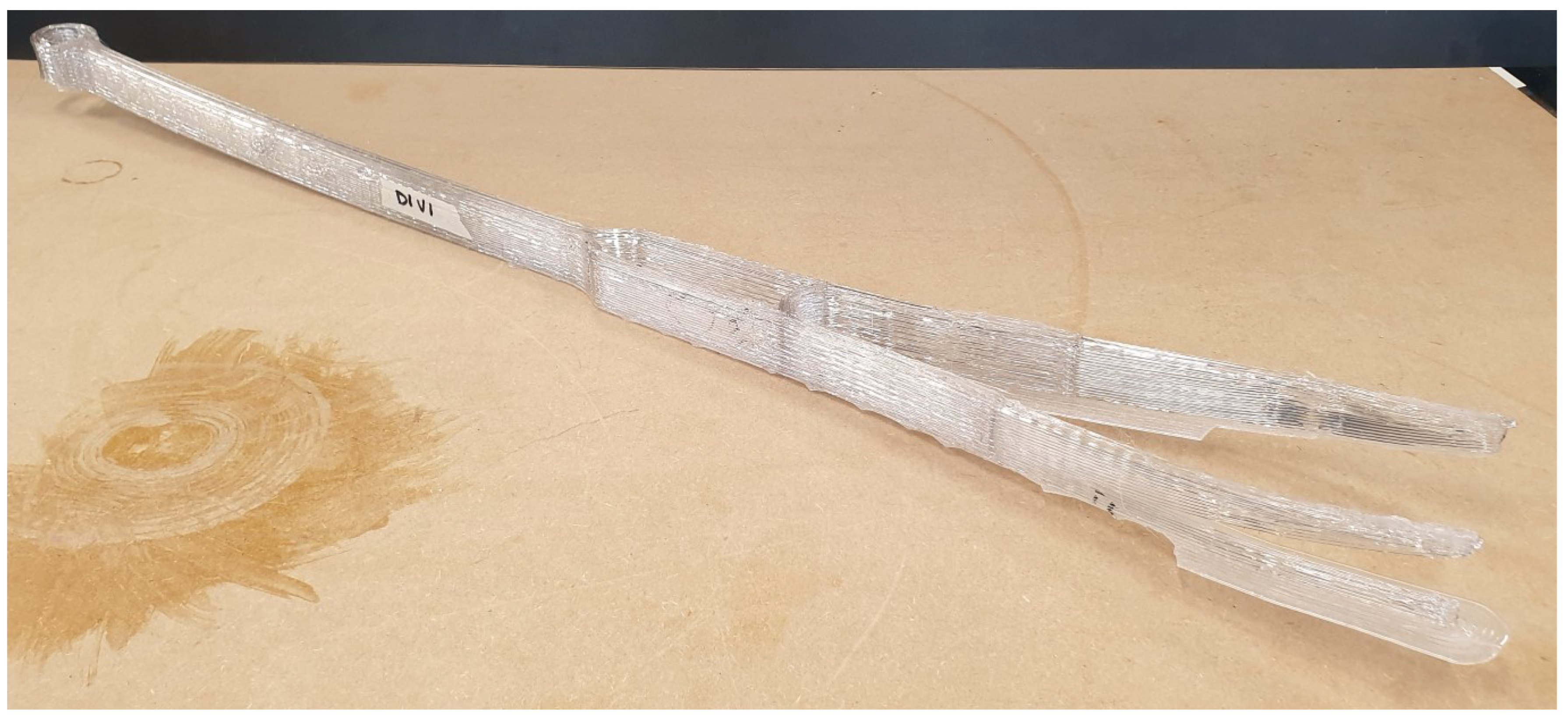
Figure 2.
Schematic representation of INDEXLAB’s robotic cell setup
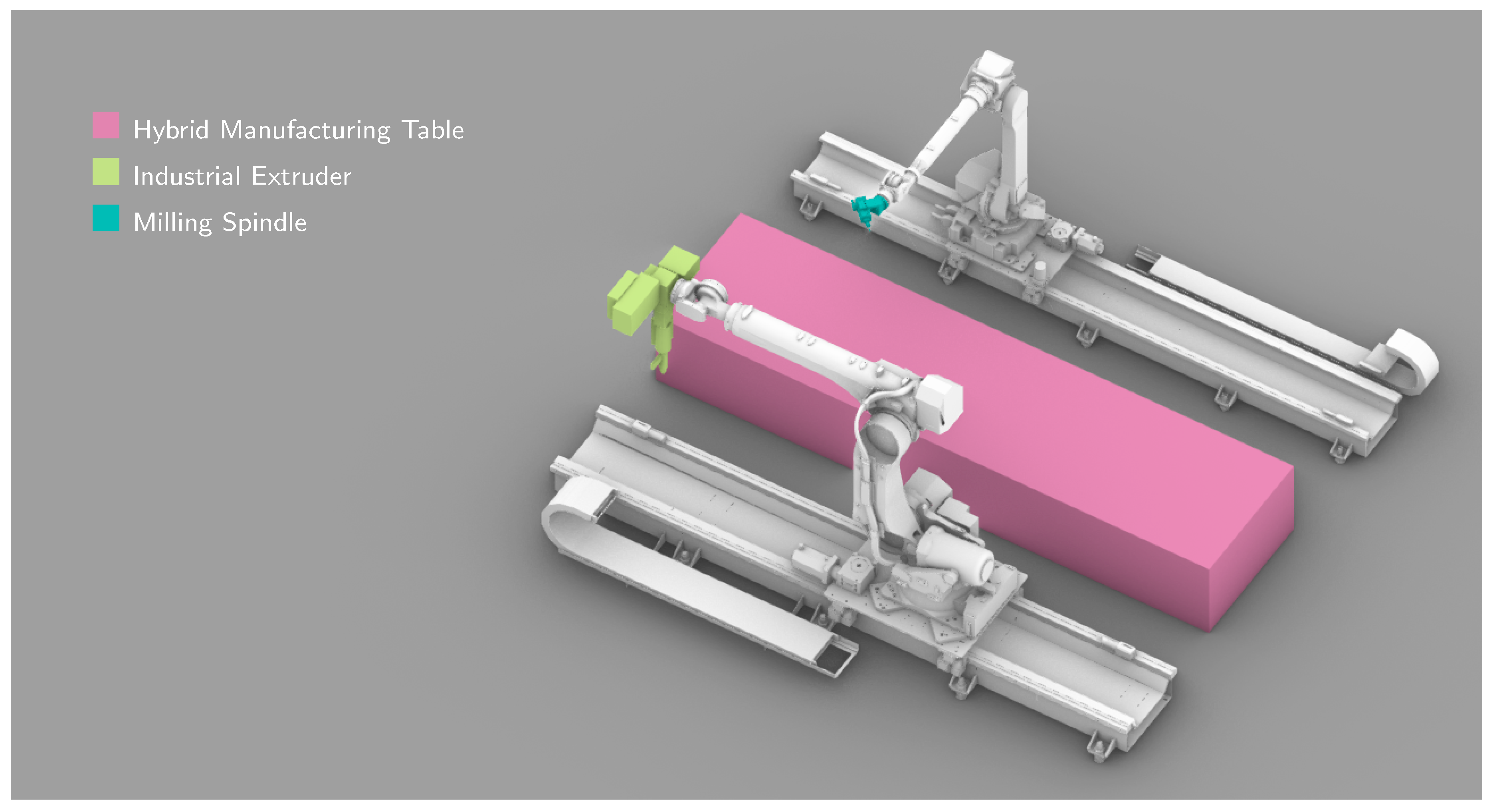
Figure 3.
Heat dissipation in a PC wall printed with a symmetric toolpath of adjacent layers, in two photos dated 7th of February, 2022 taken in INDEXLAB with a FLIR thermo-camera. The distinct color transition highlights the rapid cooling rate of PC when printing without a thermostatic cell, at an ambient temperature of 21-22 °C approximately. The most recently deposited layers cool rapidly reaching nearly 50% of the extrusion temperature within seconds. After approximately 5 minutes, the first dozen layers of the print exhibit a temperature reduction of roughly 70% relative to the extrusion temperature.
Figure 3.
Heat dissipation in a PC wall printed with a symmetric toolpath of adjacent layers, in two photos dated 7th of February, 2022 taken in INDEXLAB with a FLIR thermo-camera. The distinct color transition highlights the rapid cooling rate of PC when printing without a thermostatic cell, at an ambient temperature of 21-22 °C approximately. The most recently deposited layers cool rapidly reaching nearly 50% of the extrusion temperature within seconds. After approximately 5 minutes, the first dozen layers of the print exhibit a temperature reduction of roughly 70% relative to the extrusion temperature.
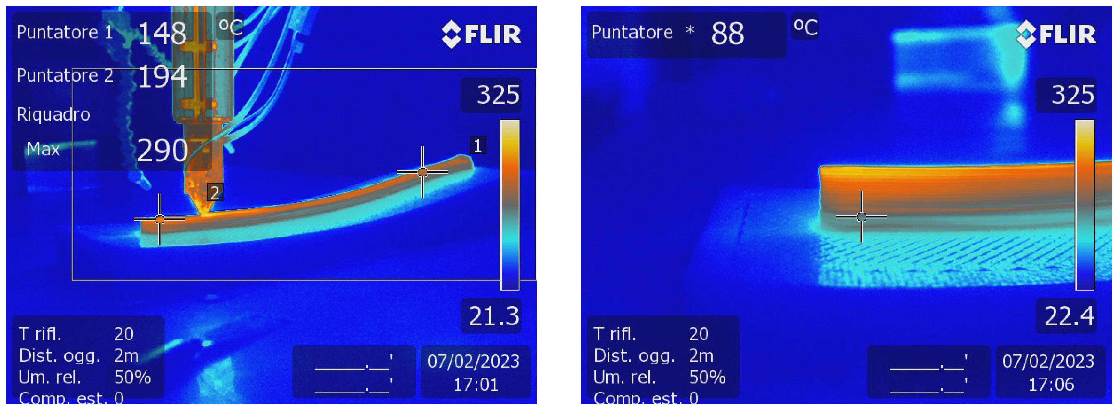
Figure 4.
From top to bottom, left to right: different print bed solutions. (a) The solution implemented by some companies uses a perforated steel sheet as print bed for LFAM 3DP. Over-extruding the first layer, the polymer spills inside the ordered pattern of holes and grips to it, reducing warping. (b) A second solution, extracted from the Method for Producing Objects 2022 patent by Maccagnan and Ruttico, uses a sandwich panel engraved at the top to constrain the molten polymer expansion within an honeycomb pattern. In this case, the engineering of the print bed can be the driver of new research directions. (c and d) Superframe [18] is a system to construct discretized double-curved façades which uses 3DP to produce engineered skins, wholly embedded cladding systems for design and architecture.
Figure 4.
From top to bottom, left to right: different print bed solutions. (a) The solution implemented by some companies uses a perforated steel sheet as print bed for LFAM 3DP. Over-extruding the first layer, the polymer spills inside the ordered pattern of holes and grips to it, reducing warping. (b) A second solution, extracted from the Method for Producing Objects 2022 patent by Maccagnan and Ruttico, uses a sandwich panel engraved at the top to constrain the molten polymer expansion within an honeycomb pattern. In this case, the engineering of the print bed can be the driver of new research directions. (c and d) Superframe [18] is a system to construct discretized double-curved façades which uses 3DP to produce engineered skins, wholly embedded cladding systems for design and architecture.
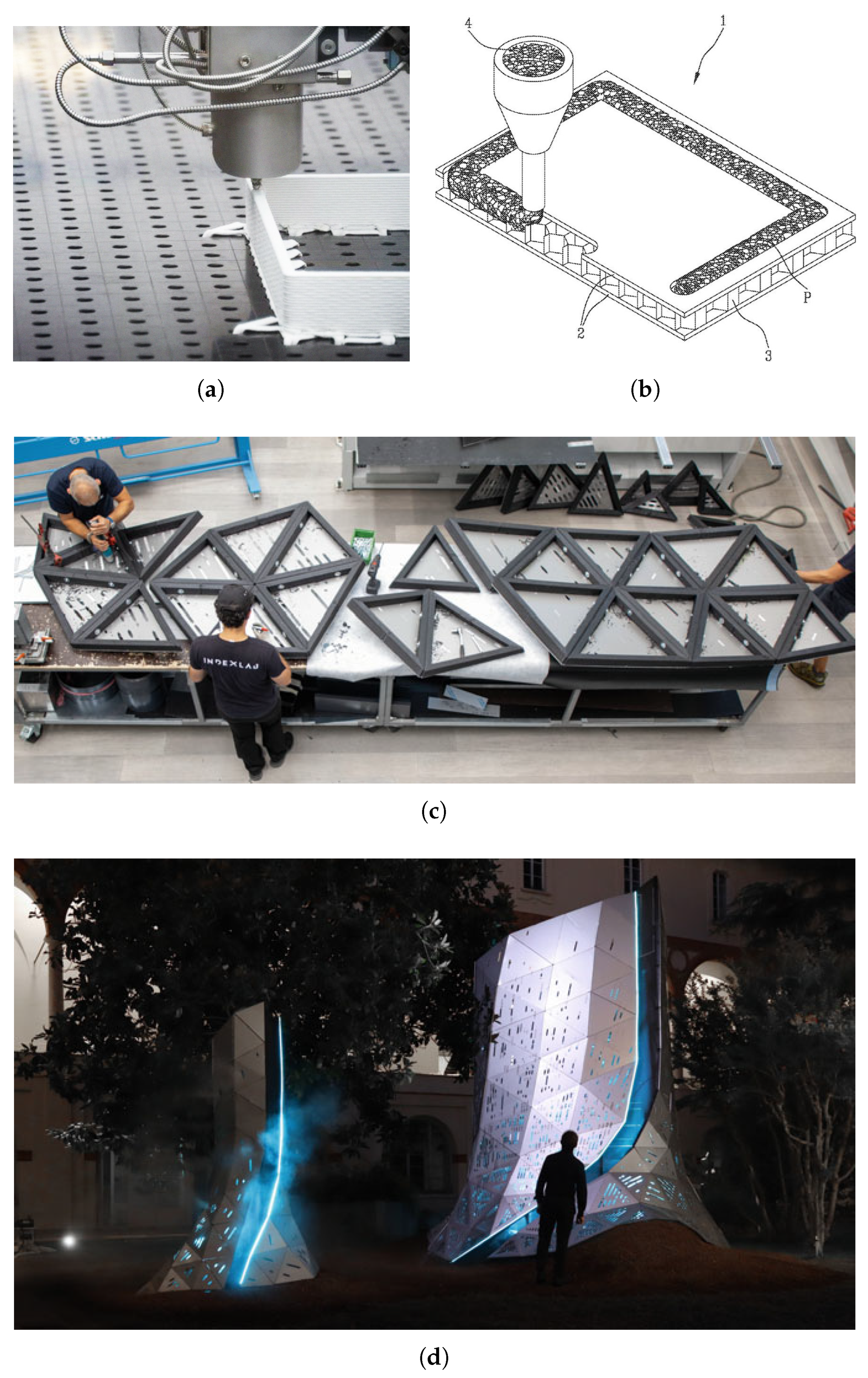
Figure 5.
Detail of OneLineTwoCoils showing the surface characteristics.
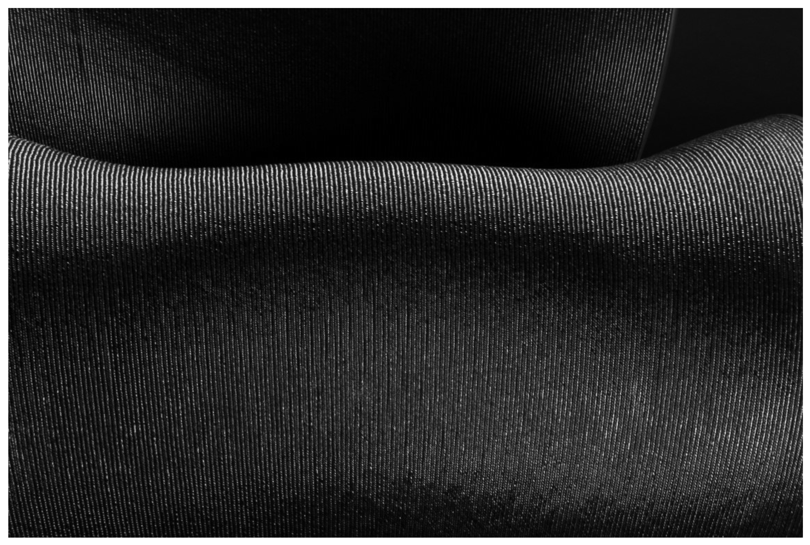
Figure 6.
Prototype D15V12 dated 20th of April, 2022 of New01Bike: first delivered working prototype, printed in conformal mode in CLH employing LATI-A PC. The un-treated surface finish exposes the manufacturing process and highlights the geometric principle behind the design of the frame.
Figure 6.
Prototype D15V12 dated 20th of April, 2022 of New01Bike: first delivered working prototype, printed in conformal mode in CLH employing LATI-A PC. The un-treated surface finish exposes the manufacturing process and highlights the geometric principle behind the design of the frame.
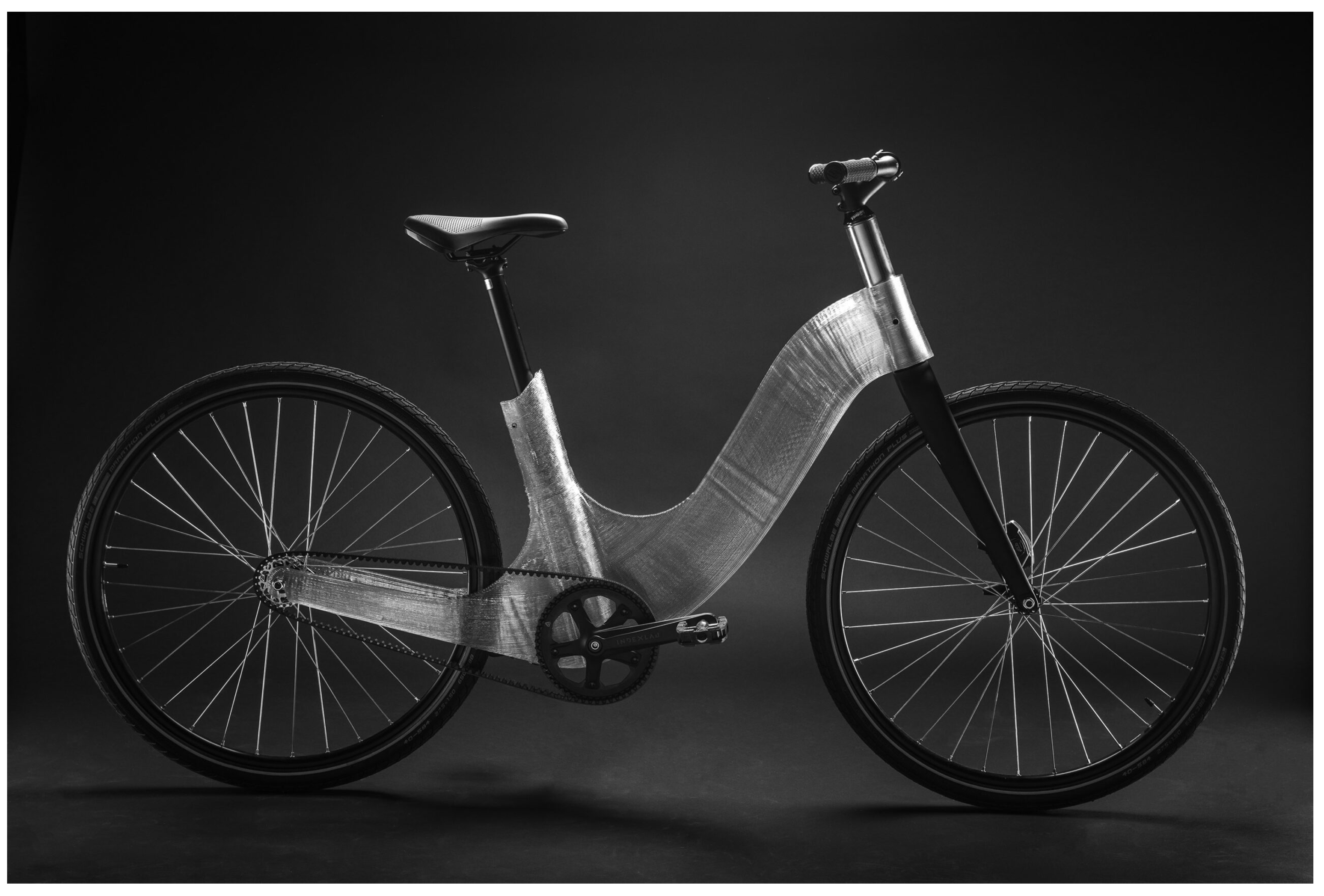
Figure 7.
(a) Simple FEM analysis of the first 3D model, in a Autodesk Fusion 360 screenshot dated 22th of February, 2022. Even if it does not take into account the 3DP process, as if the model was manufactured through injection molding, the main load path criticalities suggest that, if the mold’s geometrical development follows the bottom part of the bike frame, non-structural scrap material is reduced to the minimum. (b) Mold mapping process performed with a calibration tool, in a photo dated 28th of February, 2022.
Figure 7.
(a) Simple FEM analysis of the first 3D model, in a Autodesk Fusion 360 screenshot dated 22th of February, 2022. Even if it does not take into account the 3DP process, as if the model was manufactured through injection molding, the main load path criticalities suggest that, if the mold’s geometrical development follows the bottom part of the bike frame, non-structural scrap material is reduced to the minimum. (b) Mold mapping process performed with a calibration tool, in a photo dated 28th of February, 2022.
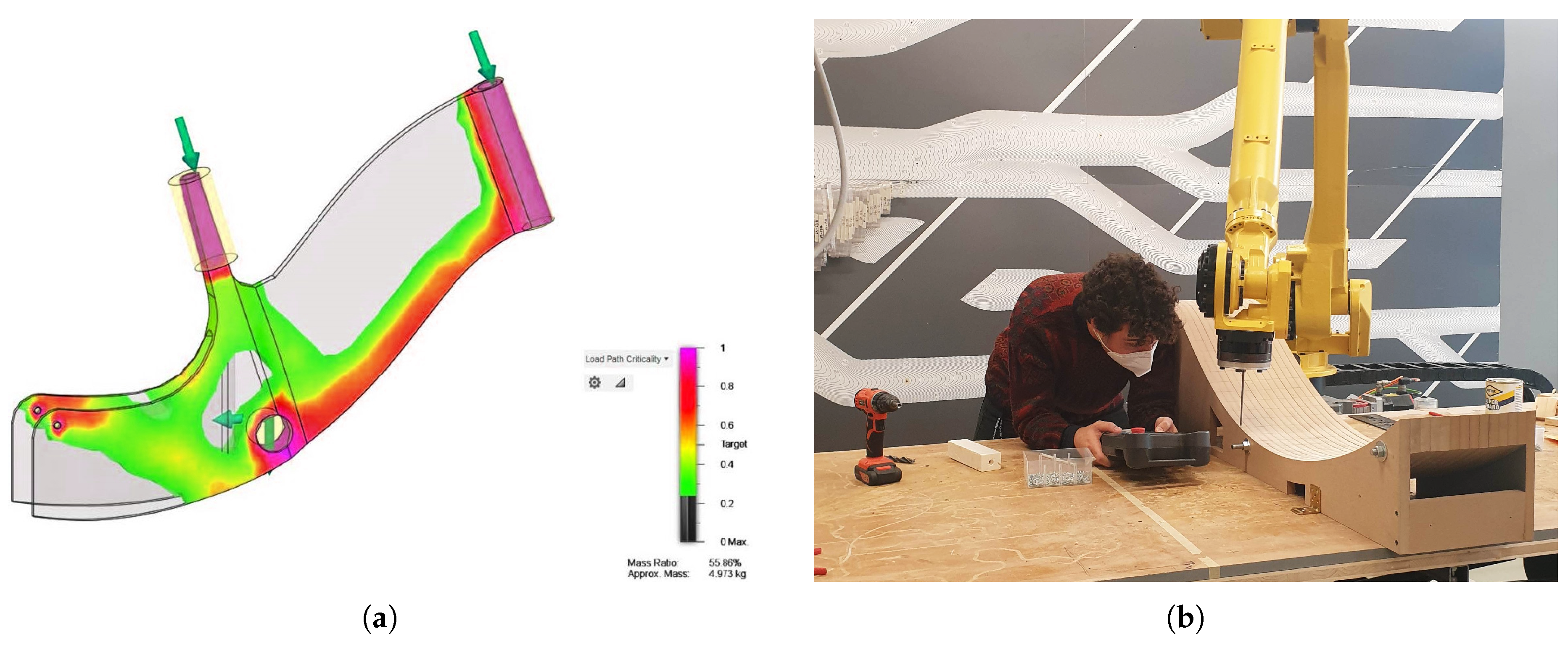
Figure 8.
From top to bottom, left to right:. (a and b) Prototype D13V9 dated 1st of April, 2022 of New01Bike: details of brittle failure in the rear dropout. (c) Prototype D13V9 dated 15th of April, 2022 of New01Bike: view of the bottom of the frame geometry over the interface with the seat post after the milling operation. The double-perimeter shell delays thermal dissipation by creating TBs, which take the form of vertical chimney-like cavities that retain the molten polymer’s heat.
Figure 8.
From top to bottom, left to right:. (a and b) Prototype D13V9 dated 1st of April, 2022 of New01Bike: details of brittle failure in the rear dropout. (c) Prototype D13V9 dated 15th of April, 2022 of New01Bike: view of the bottom of the frame geometry over the interface with the seat post after the milling operation. The double-perimeter shell delays thermal dissipation by creating TBs, which take the form of vertical chimney-like cavities that retain the molten polymer’s heat.
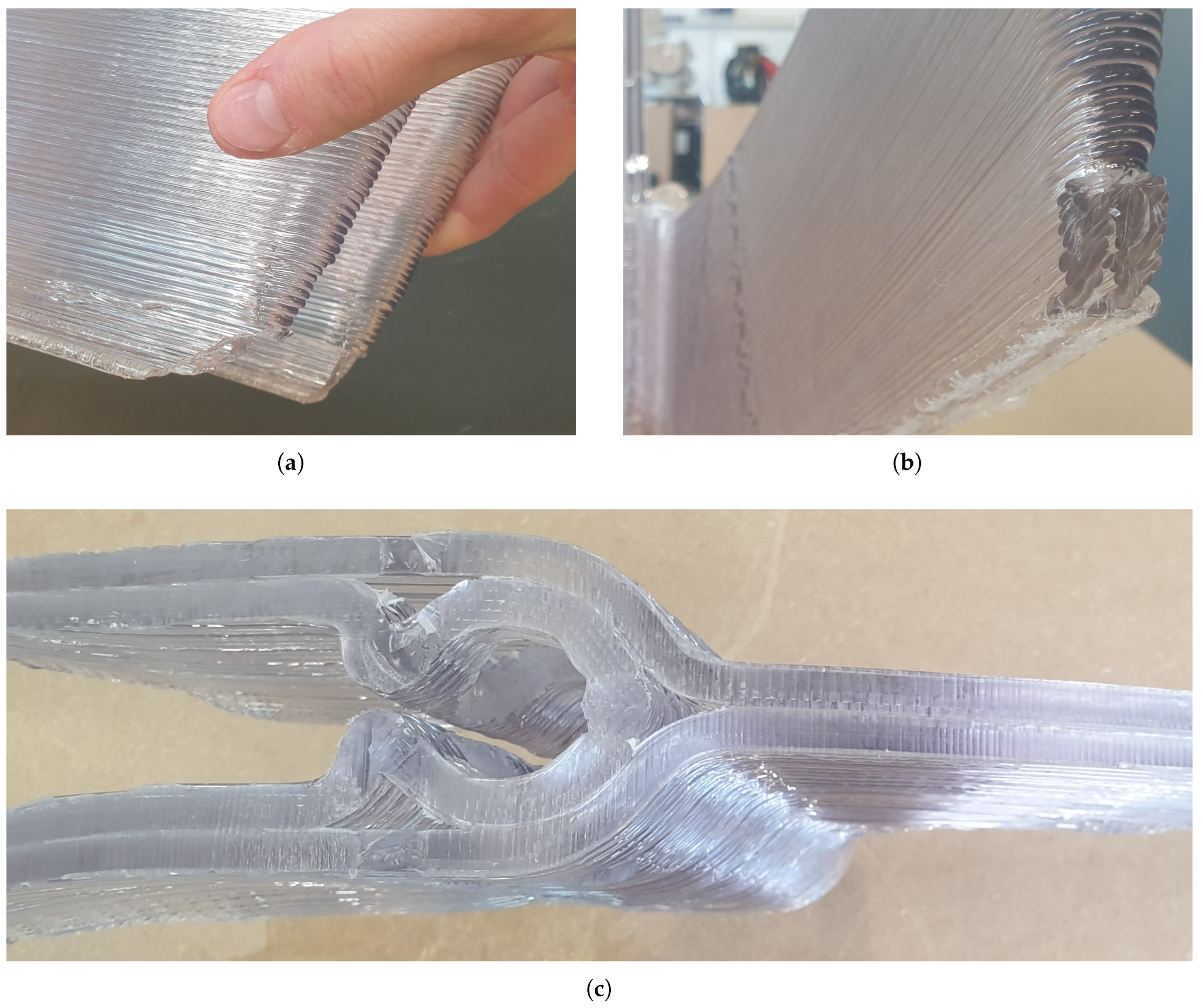
Figure 10.
Slicing differences between: (a) CLH and (b) ALH version of New01Bike. While slicing with offset surface breaks the toolpath’s continuity after 490 mm, slicing with tweened surfaces enables adding, changing, removing slicing surfaces 1, 2, 3, 4 with the manufacturer needs, with the need of adapting the frame to other proportions or constraints. Since the milling line remains in the same position, it is convenient that slicing surface 2 coincides with it.
Figure 10.
Slicing differences between: (a) CLH and (b) ALH version of New01Bike. While slicing with offset surface breaks the toolpath’s continuity after 490 mm, slicing with tweened surfaces enables adding, changing, removing slicing surfaces 1, 2, 3, 4 with the manufacturer needs, with the need of adapting the frame to other proportions or constraints. Since the milling line remains in the same position, it is convenient that slicing surface 2 coincides with it.
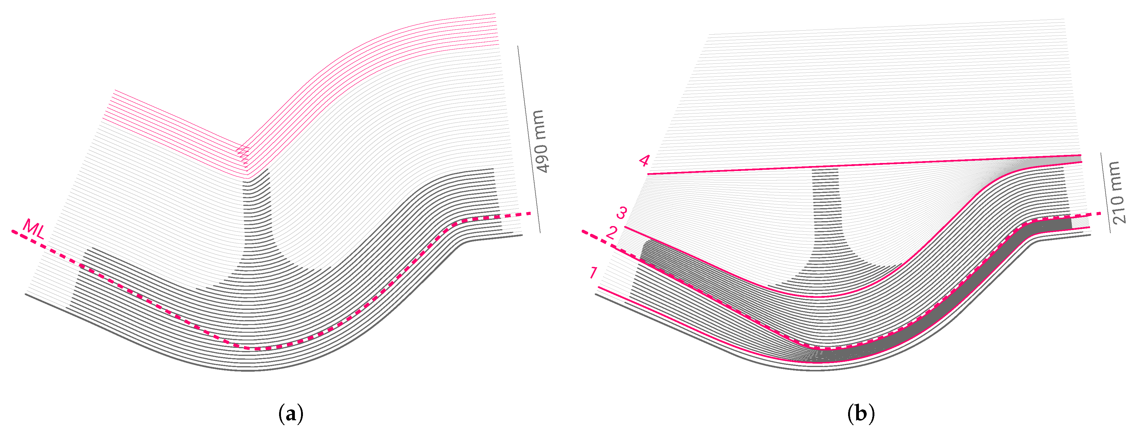
Figure 11.
(a) Version dated 9th of September, 2022 of New01Bike on display at the Pinakothek der Moderne in Munich. (b) Axonometric view, (c) plan and (d) elevation of New01Bike ’s ALH prototype extracted from US Design Patent USD1068565S. Conceived as a spatial structure, the bike frame widens and thickens incorporating air voids in correspondence with the down tube and the rear dropout.
Figure 11.
(a) Version dated 9th of September, 2022 of New01Bike on display at the Pinakothek der Moderne in Munich. (b) Axonometric view, (c) plan and (d) elevation of New01Bike ’s ALH prototype extracted from US Design Patent USD1068565S. Conceived as a spatial structure, the bike frame widens and thickens incorporating air voids in correspondence with the down tube and the rear dropout.
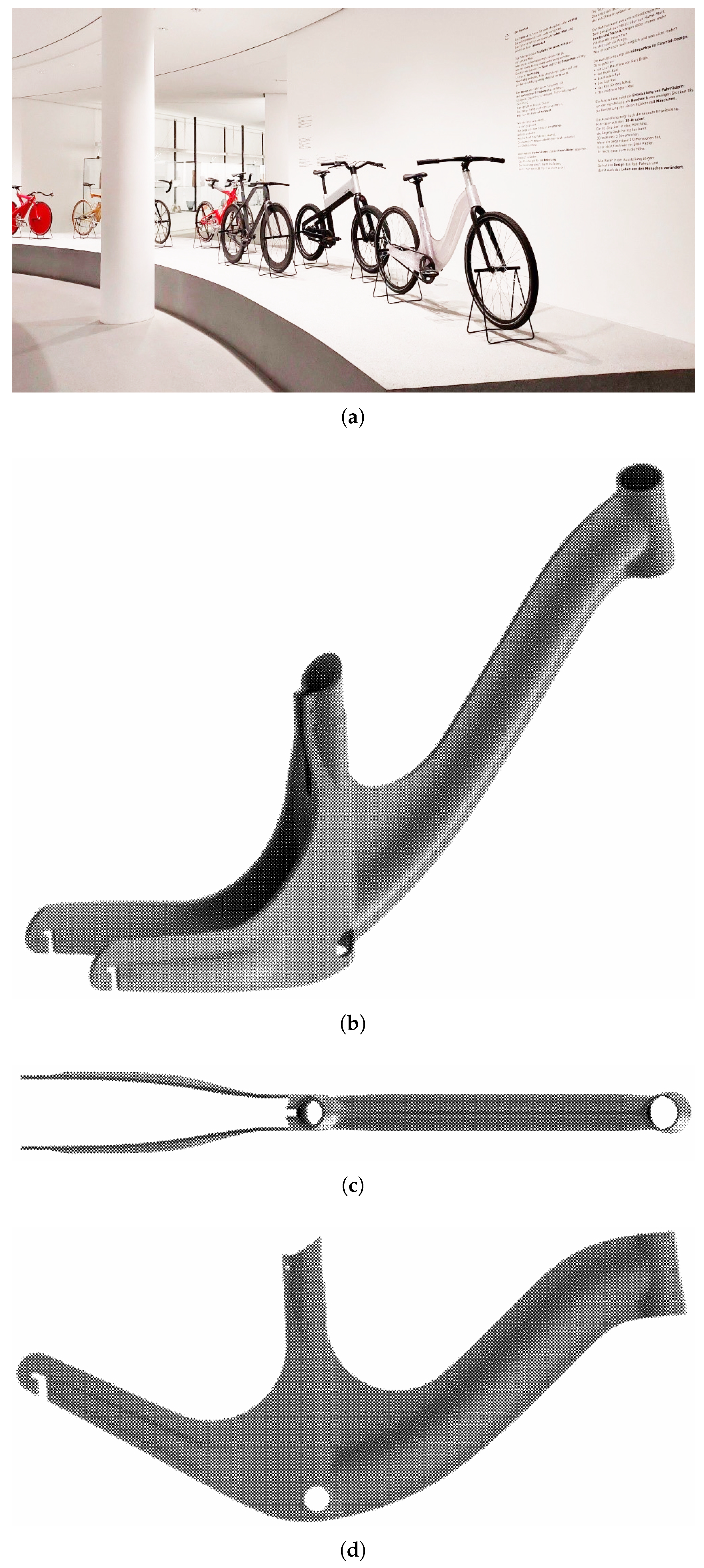
Figure 13.
From top to bottom, left to right:. (a) Amarcord’s D2V9 minimum LH section portion, in a photo dated 23th of June, 2022. Amarcord’s D5V13 section prototype, showing (b) elevation, and (c) focus on minimum and (d) maximum LH portions, in three photos dated 30th of June, 2022. Amarcord’s D6V18 section prototype, showing (e) the top view, (f) the full piece elevation, and focus on minimum (g) and (h) maximum LH portion’ side, in four photos dated 7th of July, 2022.
Figure 13.
From top to bottom, left to right:. (a) Amarcord’s D2V9 minimum LH section portion, in a photo dated 23th of June, 2022. Amarcord’s D5V13 section prototype, showing (b) elevation, and (c) focus on minimum and (d) maximum LH portions, in three photos dated 30th of June, 2022. Amarcord’s D6V18 section prototype, showing (e) the top view, (f) the full piece elevation, and focus on minimum (g) and (h) maximum LH portion’ side, in four photos dated 7th of July, 2022.
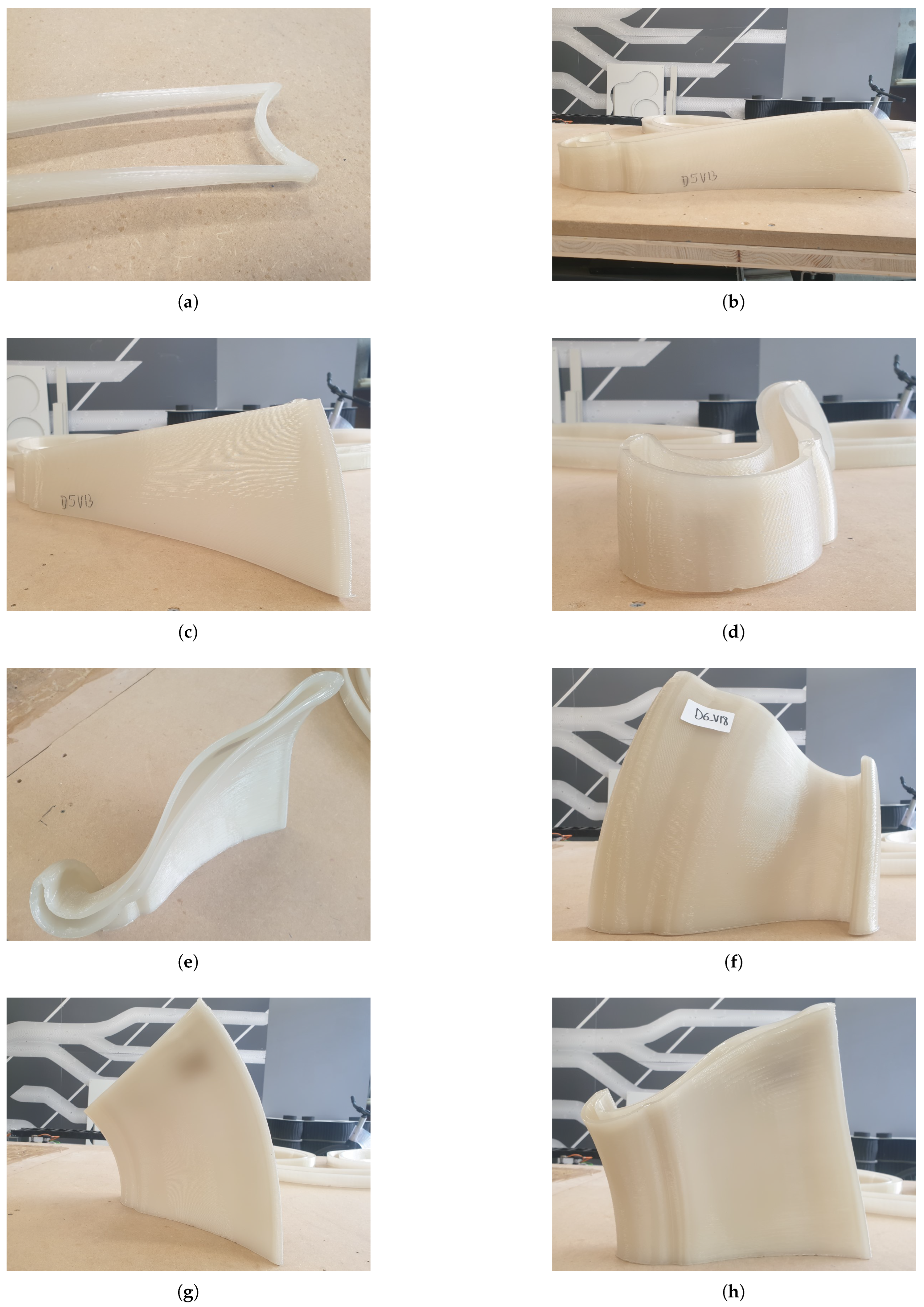
Figure 14.
From top to bottom, left to right:. (a) A fraction of Meryl Bougo’s and Andrea Barberi dance movements, and (b) visualisation of motion-tracking as point cloud data at GPEM Headquarters in Genova (GE), in two photos dated 20th of April, 2022. (c) The overall development of the trajectory discretized in lines and arcs and numbered according to the linear portions’ sequence, in a screenshot of a Rhinoceros viewport dated 23th of February, 2023. (d) CNC-machine bending a tube portion at FASB linea due production facility in Cremella (LC), in a photo dated 6th of March, 2023. (e) AR-guided assembly of Amarcord employing Microsoft HoloLens 2 at INDEXLAB in Lecco, in a photo dated 8th of March, 2023. Before riveting each pipe’s end and locking the final 3D configuration in place, simple duct tape was used to temporarily constrain the rotation of each pipe segment relative to the next. (f) Sweep portioning and selection, (g) examination of robot toolpath for AM, (h) LFAM employing Fanuc R-2000iC 210L robot with a steep EOAT inclination, in three photos dated 24th of March, 2023.
Figure 14.
From top to bottom, left to right:. (a) A fraction of Meryl Bougo’s and Andrea Barberi dance movements, and (b) visualisation of motion-tracking as point cloud data at GPEM Headquarters in Genova (GE), in two photos dated 20th of April, 2022. (c) The overall development of the trajectory discretized in lines and arcs and numbered according to the linear portions’ sequence, in a screenshot of a Rhinoceros viewport dated 23th of February, 2023. (d) CNC-machine bending a tube portion at FASB linea due production facility in Cremella (LC), in a photo dated 6th of March, 2023. (e) AR-guided assembly of Amarcord employing Microsoft HoloLens 2 at INDEXLAB in Lecco, in a photo dated 8th of March, 2023. Before riveting each pipe’s end and locking the final 3D configuration in place, simple duct tape was used to temporarily constrain the rotation of each pipe segment relative to the next. (f) Sweep portioning and selection, (g) examination of robot toolpath for AM, (h) LFAM employing Fanuc R-2000iC 210L robot with a steep EOAT inclination, in three photos dated 24th of March, 2023.
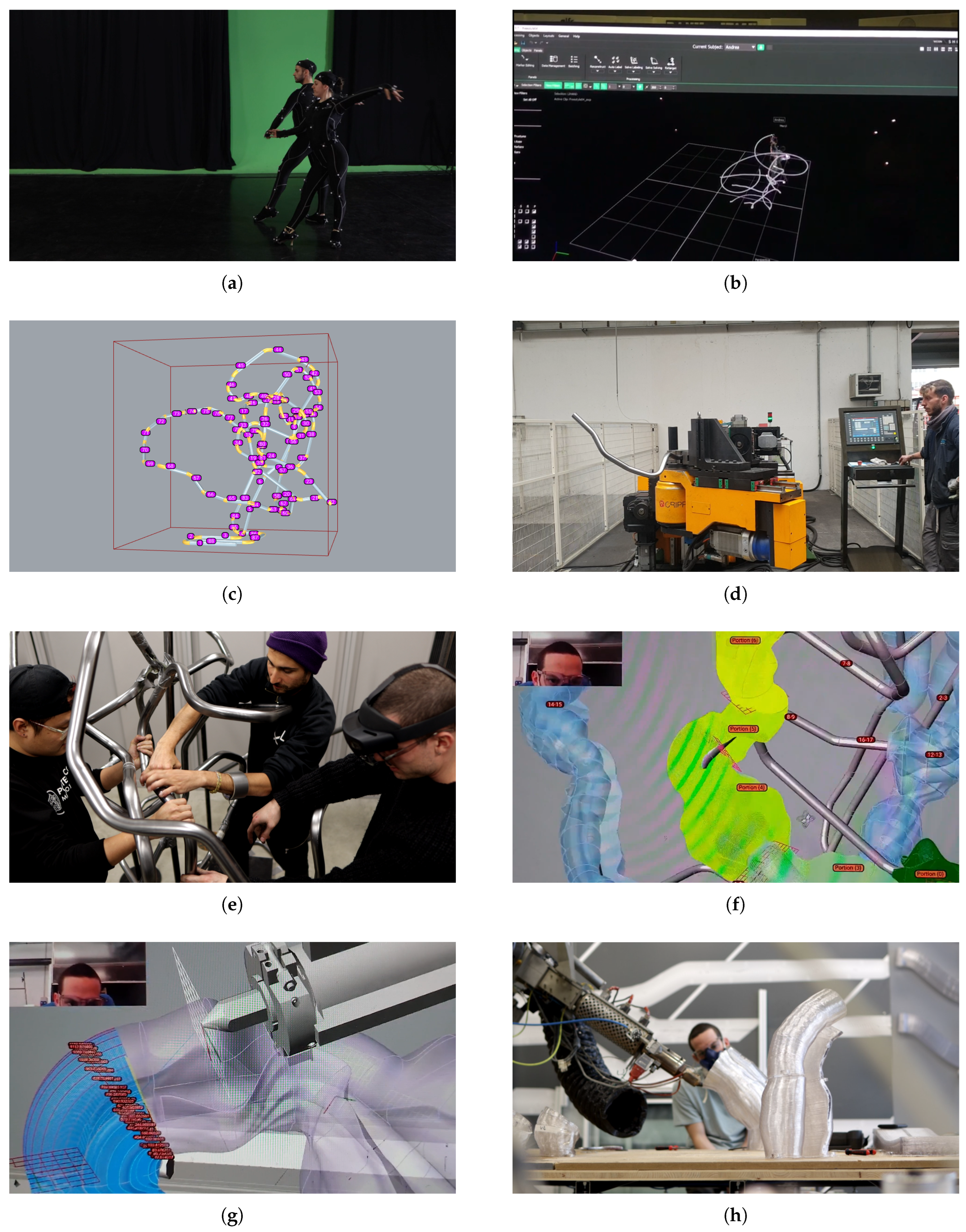
Figure 15.
Divided by the pipe-fitting section opening at the center, at the left end of Amarcord’s sweep type section a larger tube-like section creates TB 1 and, at the right, a canyon-like creased shape creates TB 2.
Figure 15.
Divided by the pipe-fitting section opening at the center, at the left end of Amarcord’s sweep type section a larger tube-like section creates TB 1 and, at the right, a canyon-like creased shape creates TB 2.
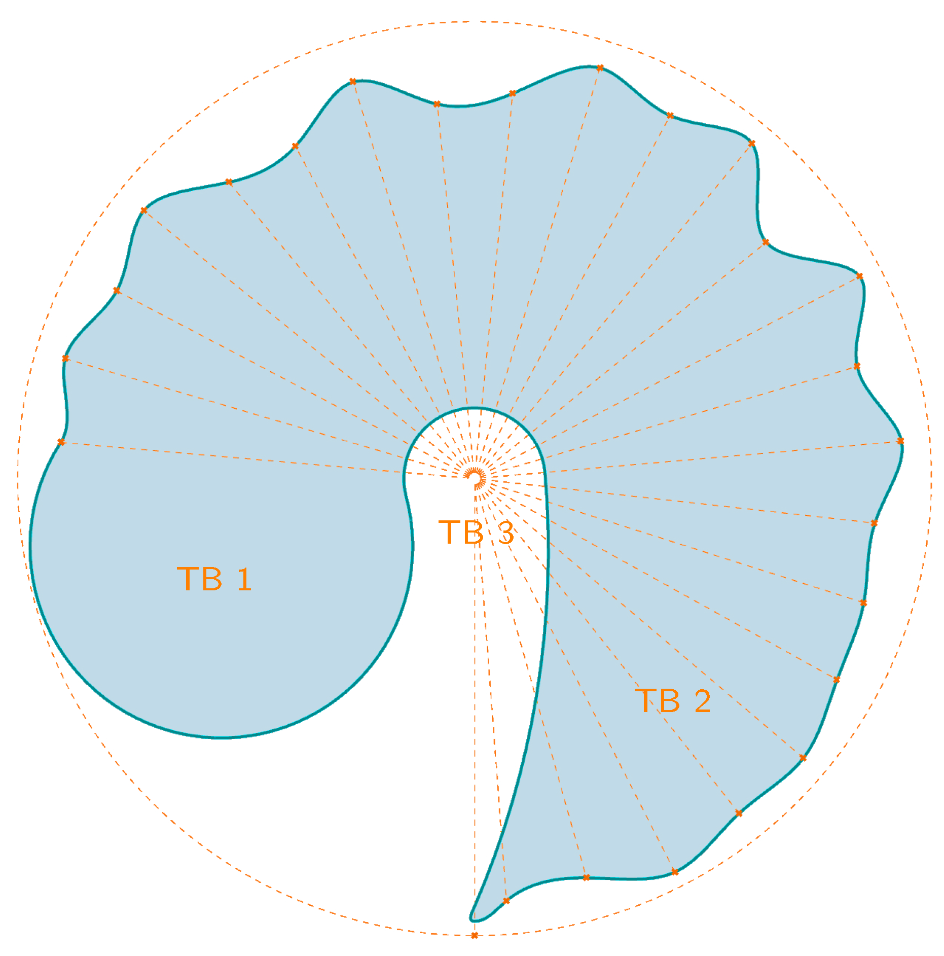
Figure 19.
OneLineTwoCoils’s print tests in INDEXLAB performed using a flat print bed, which corresponds to the chair’s axis of symmetry. On the left: (a) the first difficulties in harmonising the two extrusions of the perimeter on a non-planar last layer with an inclination of 27 °, in a photo dated 15th of July, 2022. On the right: (b and c) photos of the most successful print test, performed at 40 mm/s deposition speed, 8 mm LW, 0.56 to 2.65 LH (4.74 LHR), with a VSR of 1.10 and RPMs going from 55 to 350, in two photos dated 22th of September, 2022
Figure 19.
OneLineTwoCoils’s print tests in INDEXLAB performed using a flat print bed, which corresponds to the chair’s axis of symmetry. On the left: (a) the first difficulties in harmonising the two extrusions of the perimeter on a non-planar last layer with an inclination of 27 °, in a photo dated 15th of July, 2022. On the right: (b and c) photos of the most successful print test, performed at 40 mm/s deposition speed, 8 mm LW, 0.56 to 2.65 LH (4.74 LHR), with a VSR of 1.10 and RPMs going from 55 to 350, in two photos dated 22th of September, 2022
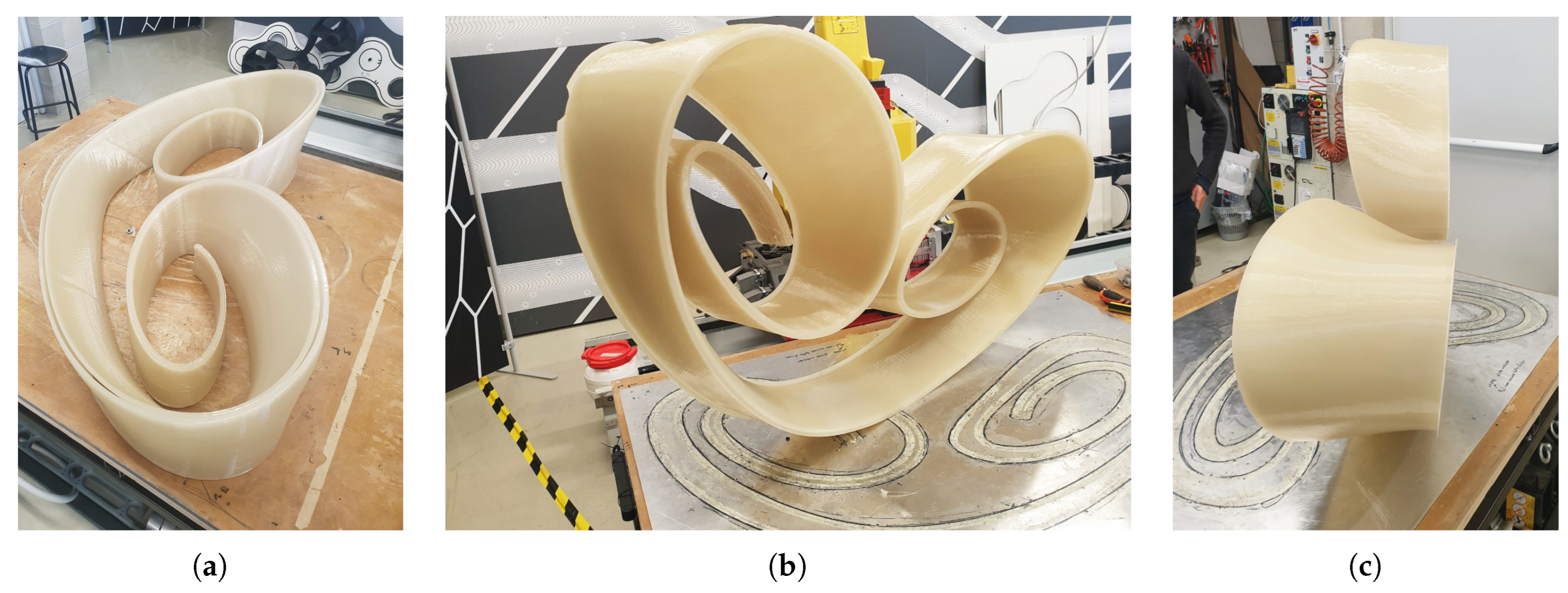
Figure 22.
Two surface polishing outcomes of OneLineTwoCoils, in correspondence with the portions of: (a) backrest and (b) external edges.
Figure 22.
Two surface polishing outcomes of OneLineTwoCoils, in correspondence with the portions of: (a) backrest and (b) external edges.
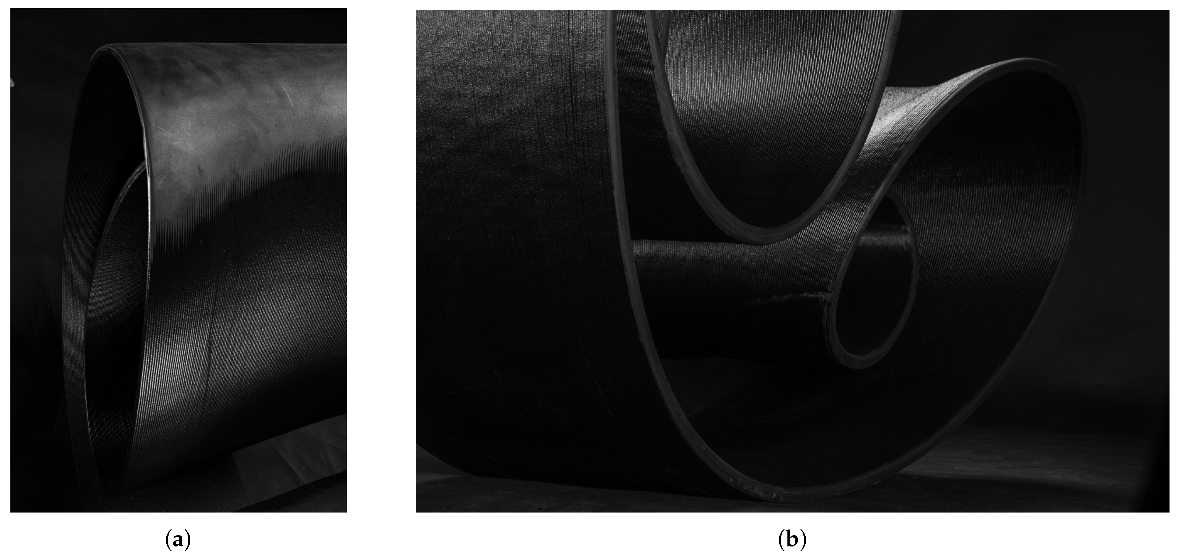
Figure 23.
The last versions of (a) New01Bike and (b) OneLineTwoCoils, both printed using LATI-D—a blend of PC pellets mixed with 30% carbon fibers.
Figure 23.
The last versions of (a) New01Bike and (b) OneLineTwoCoils, both printed using LATI-D—a blend of PC pellets mixed with 30% carbon fibers.
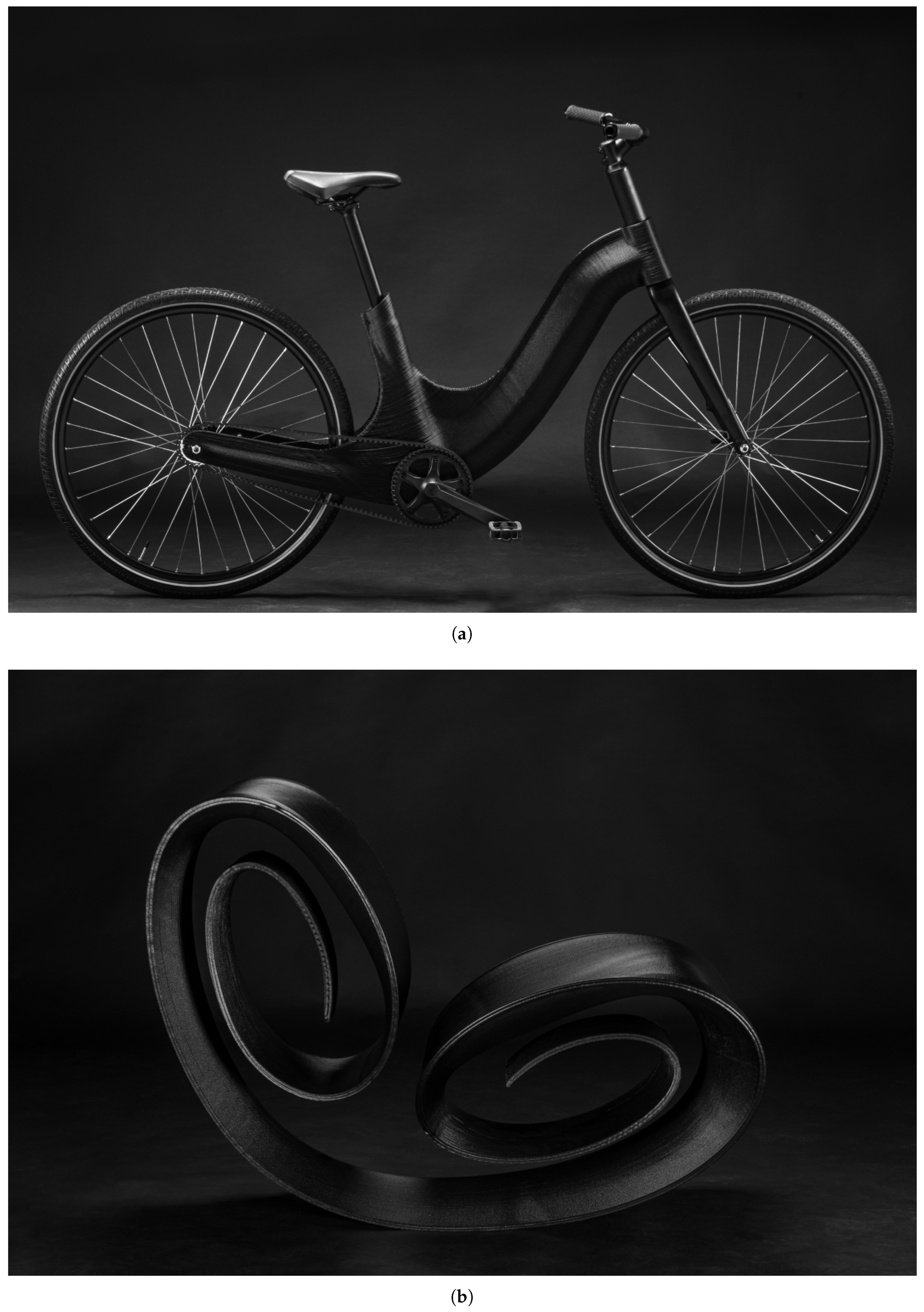
Table 1.
Comparative properties of the four material datasheets as provided by LATI S.p.A.
| Property | Reference Standard | LATI-A | LATI-B | LATI-C | LATI-D |
|---|---|---|---|---|---|
| GENERAL INFORMATION | |||||
| Production Date | 27/01/2020 | 27/09/2021 | 23/06/2022 | 30/08/2022 | |
| Lot Number | - | Lot K206203 | Lot K70869 | Lot K122239 | |
| Tested on project: | New01Bike, Amarcord | New01Bike | Amarcord, OneLineTwoCoils | New01Bike, OneLineTwoCoils | |
| Product base | Polycarbonate (PC) post-consumer | Polybutylene terephthalate (PBT) - Polycarbonate (PC) | Polycarbonate (PC) from mechanical recycling | Polycarbonate (PC) from mechanical recycling | |
| Additive | - | Carbon Fibers | - | Carbon Fibers | |
| UV stabilized | NO | NO | YES | YES | |
| PHYSICAL PROPERTIES | |||||
| Density [g/cm³] | ISO 1183 | 1.20 | 1.31 | 1.25 | 1.33 |
| Melt Flow Index (MFI) @ 230°C - 2,16kg [g/10’] | LATI | — | — | 8 | — |
| MECHANICAL PROPERTIES - INJECTION MOLDING | |||||
| Charpy impact (unnotched) [kJ/m²] - Trial Piece 80x10x4 mm | ISO 179-1eU | NR | 30 | NR | 40 |
| Charpy impact (notched) [kJ/m²] - Trial Piece 80x10x4 mm | ISO 179-1eA | 9 | 4.7 | 6.1 | 7 |
| Elongation at break [%] - Speed 5 mm/min | ISO 527-1 | >100 | 2.9 | >100 | 1.6 |
| Elongation at yield [%] - Speed 5 mm/min | ISO 527-1 | 6 | — | 4.3 | — |
| Tensile strength at break [MPa] - Speed 5 mm/min | ISO 527-1 | 65 | 125 | 35 | 175 |
| Tensile strength at yield [MPa] - Speed 5 mm/min | ISO 527-1 | 65 | — | 50 | — |
| Tensile modulus [MPa] - Speed 1 mm/min | ISO 527-1 | 2400 | 10200 | 2100 | 21000 |
| THERMAL PROPERTIES - INJECTION MOLDING | |||||
| VICAT (50 N) [°C] | ISO 306 | 145 | 177 | 85 | 177 |
| HDT (0.45 MPa) [°C] | ISO 75 | 137 | 201 | 80 | 212 |
| HDT (1.81 MPa) [°C] | ISO 75 | 125 | 142 | 71 | 168 |
| FILAMENT PROCESSING CONDITIONS | |||||
| Drying [h @ °C] | — | 4 @ 100 | 4 @ 40 | 4 @ 80 | |
| Extrusion temperature [°C] | — | 250–265 | 250 | 270–280 | |
| 3D PRINTING CONDITIONS | |||||
| Nozzle temperature [°C] | — | 265 | — | — | |
| Bed temperature [°C] | — | 60 | — | — | |
| Print speed [mm/s] | 20 | 40 | — | — | |
| INJECTION MOLDING CONDITIONS | |||||
| Melt temperature [°C] | — | 250 | — | — | |
| Mold temperature [°C] | — | 80 | — | — | |
Table 2.
Correlation of LH and motor RPM parameters for LATI-A PC for two layer width ranges, extruded in INDEXLAB at 60 mm/s deposition speed at an ambient temperature of 22 °C. Height measurements are verified with a caliper once the printed part has solidified.
Table 2.
Correlation of LH and motor RPM parameters for LATI-A PC for two layer width ranges, extruded in INDEXLAB at 60 mm/s deposition speed at an ambient temperature of 22 °C. Height measurements are verified with a caliper once the printed part has solidified.
| Layer width 7–8 mm | Layer width 5–6 mm | ||
|---|---|---|---|
| LH (mm) | RPM | LH (mm) | RPM |
| 0.09 | 10 | 0.26 | 33 |
| 0.14 | 15 | 0.68 | 85 |
| 0.32 | 40 | 0.72 | 90 |
| 0.45 | 56 | 0.91 | 140 |
| 0.52 | 65 | 1.38 | 213 |
| 0.94 | 145 | 1.82 | 300 |
| 2.00 | 330 | 1.87 | 310 |
| 2.14 | 353 | 1.92 | 317 |
| 2.15 | 355 | ||
| 2.57 | 425 | ||
Disclaimer/Publisher’s Note: The statements, opinions and data contained in all publications are solely those of the individual author(s) and contributor(s) and not of MDPI and/or the editor(s). MDPI and/or the editor(s) disclaim responsibility for any injury to people or property resulting from any ideas, methods, instructions or products referred to in the content. |
© 2026 by the authors. Licensee MDPI, Basel, Switzerland. This article is an open access article distributed under the terms and conditions of the Creative Commons Attribution (CC BY) license (http://creativecommons.org/licenses/by/4.0/).
Copyright: This open access article is published under a Creative Commons CC BY 4.0 license, which permit the free download, distribution, and reuse, provided that the author and preprint are cited in any reuse.