

Submitted:
11 September 2026
Posted:
14 September 2026
You are already at the latest version
Abstract
Thick and ultra-thick coal seams contain large resources; however, greater extraction heights amplify strata movement, coal wall instability, support demand, gas and fire hazards, dilution, and interruption risk. This review develops and foregrounds a conceptual six-gate, non-compensatory “study-to-assurance” framework that turns thick-seam method selection, demonstration, replication, and cross-mine transfer into an explicit evidence-to-decision pathway rather than a one-off design event. The framework specifies minimum evidence sets, auditable artifacts, and pass/conditional-hold/stop outcomes at six stages, from resource screening and geotechnical characterization to integrated design, instrumented demonstration, second-panel replication, and transfer to new blocks or mines. To support and bound this architecture, a structured critical review of literature and grey sources from 1950 to 2025 identified 300 records; 190 were screened, 145 full texts were assessed, and 120 sources were included across ten extraction or boundary option systems. Continuous miners have emerged as India’s most scalable mechanized underground system within a bounded cutting envelope, whereas high-reach single-pass longwalls deliver high outputs only within narrow geomechanical and operational windows. Although longwall top coal caving appears to address the residual height problem, it remains undeveloped in India. Historical blasting galleries, multislice, sublevel-caving, hydraulic, and descending-shield experiences are therefore not used as templates to revive but as engineering evidence that shapes the gate thresholds and failure tests. The proposed six-gate framework integrates evidence quality, geomechanical compatibility, coupled hazards, operational continuity, lifecycle economics, responsibility, and energy transition reporting. Its quantitative thresholds are demonstration minima, not statutory limits or design guarantees, and require field validation and mine-specific recalibration to be effective.
Keywords:
round-control assurance
; statutory scientific studies
; mine safety governance
; performance-based regulation
; technology lifecycle evaluation
; risk-informed design
1. Introduction
The engineering problem posed by a thick coal seam is deceptively simple: the resource thickness exceeds the height that can be extracted safely, continuously, and economically using conventional production units. The resulting challenge is not merely to cut more coal. Increasing the extraction height changes the stress redistribution, size and geometry of the caving zone, coal wall exposure, support loading, ventilation pathways, gas release, spontaneous heating potential, dilution and subsidence. A method that performs well in a persistent, gently dipping seam with a competent floor and predictable caving can become unreliable in a banded seam beneath massive sandstone or above a weak and water-sensitive floor [1,2,3,4,5].
Therefore, a “thick seam” is a technology-dependent and geological description of a coal seam. For inventory and comparison, this review adopted the established Indian operational threshold of a total mineable thickness ≥ 4.8 m [3,78]. For method selection, it also reports the residual thickness Δt = t_seam − h_cut, where h_cut is the repeatable cutting height supported by a mine-specific design. A seam is termed ultra-thick when contemporary high-reach cutting leaves a substantial recoverable upper coal band. This is a functional category rather than a universal legal threshold for mining. For example, a 5.2 m seam is thick relative to a 4.6 m continuous miner cutting envelope (Δt = 0.6 m) but may lie within a validated 5.5 m high-risk surface-penetration level (HR-SPL) envelope. An 8.0 m seam cut at 5.5 m leaves 2.5 m of roof coal and therefore remains a thick-seam recovery problem, even though the lower horizon is mechanically minable. The tables consequently state both the total seam thickness and cutting or drawing height so that identical geologies are not assigned contradictory labels.
India has an unusually rich record of experimentation with thick-seam coal mining. Conventional multi-section bord-and-pillar working, splitting and slicing, hydraulic stowing, cable-bolt-assisted single-lift extraction, blasting-gallery mining, continuous miner depillaring, multislice longwall, longwall sublevel caving, hydraulic mining, descending shields, powered-support longwalls, high-reach single-pass longwalls, and longwall top coal caving (LTCC) have all been used and evaluated previously. Although these records include important technical achievements, their adoption remains inconsistent. Some systems completed a panel without replication, whereas others were discontinued for a combination of geological, equipment, organizational, economic, and mine life-related reasons. Therefore, a mine-level association must not be converted into a method-level causal claim without direct evidence to support it.
The contemporary context is also important. The mechanized underground production of Coal India Limited (CIL) has expanded through continuous mining and selected longwall mining. CMPDI reported 32 continuous miner systems and three bolter miner systems operating in 24 CIL mines in 2024–2025, whereas powered-support longwalls were operating at Moonidih and Jhanjra [1,2]. These deployments show that mechanization is increasing, but they do not resolve the full height recovery problem. Continuous miners commonly work within a bounded cutting envelope, and high-reach longwalls demand geological continuity, capable gate roads, reliable coal clearance, and stable shield–strata interaction. For seams beyond the practical cutting height, LTCC is a credible option; however, its suitability depends on top-coal cavability, drawing behavior, gas and fire control, and rear conveyor operability rather than seam thickness alone [6,7,8,9].
Previous studies have typically examined a single technology, mine, or geotechnical mechanism. The literature is fragmented among peer-reviewed rock mechanics studies, operator reports, government documents, conference proceedings, theses, and mine records. This fragmentation encourages three recurrent errors: treating demonstration as commercial maturity, transferring overseas production rates without transferring the complete operating system, and comparing nominal recovery values calculated on different bases. A critical synthesis must instead separate four outcomes: (i) technical feasibility, meaning that the method can operate under the stated conditions; (ii) panel success, meaning that a planned extraction unit was completed safely and with acceptable recovery; (iii) sustained performance, meaning that production, recovery, and reliability were maintained over successive panels; and (iv) scalability, meaning that the system was replicated across mines without an unacceptable loss of performance.
This review addresses the following three questions: First, what engineering problem does each thick-seam method solve, and what new constraints does it introduce? Second, why have Indian applications achieved different levels of continuity and replication? Third, what evidence is required before a technology progresses from prefeasibility to demonstration and industry-scale adoption? This study provides an integrated comparison of extraction mechanisms, a source-sensitive interpretation of the Indian experience, and a staged selection framework in which geological compatibility, hazard control, production continuity, and life-cycle economics are assessed as individual systems.
1.1. Position Relative to Prior Reviews
Ghose’s global survey [4] and Singh’s Indian mining text [3] established the historical method taxonomy, whereas Kumar; et al. [78] focused on the total thickness of single-lift variants and their practical 10–12 m limit. Khanal; et al. [61,62] provided an Indian LTCC prefeasibility and mine-scale modelling case, and Le; et al. [8] reviewed the LTCC cavability methods.
This study has three deliberately separated contributions. First, it articulates a six-gate, non-compensatory study-to-assurance architecture with explicit pass, conditional-hold, and stop outcomes; minimum evidence sets; role ownership; auditable artifacts; and distinct tests for demonstration, replication, and cross-block transfer. Second, it adapts established elements—PRISMA-informed reporting, AACODS-informed grey literature appraisal, published cavability and support criteria, and mine-specific geomechanical modelling—without claiming that any individual criterion is novel. Third, it consolidates dispersed Indian and international technical evidence into method-wise performance envelopes and a common four-level maturity interpretation: technical feasibility, panel success, sustained performance, and scalability. The resulting framework is a conceptual technical-assurance architecture, not a prescriptive design code; its sequencing and provisional thresholds require empirical testing and refinement through instrumented-demonstration projects.
This review addresses the following three linked questions.
(1) How do the main thick-seam mining options differ in terms of the specific problems they solve, the new constraints they introduce, and the conditions under which they remain operable over time?
(2) What does the India-centered evidence show regarding continuity, traceability, and learning? Why have some Indian applications achieved sustained and repeatable performances, while others have stalled or failed to scale?
(3) What minimum traceable evidence is required at each stage of a study-to-assurance lifecycle before a thick-seam technology is taken from prefeasibility to demonstration and then to wider adoption?
1.2. Energy-Transition and Ethical Context
India’s Long-Term Low-Carbon Development Strategy places coal sector decisions within a net-zero-by-2070 pathway and updated 2030 commitments on non-fossil electricity capacity and emissions intensity [82]. This does not make underground recovery questions irrelevant: coal remains part of the near- and medium-term system, and unplanned sterilization, fires, and methane leakage have material and environmental consequences. This means that a new thick-seam project must be justified against demand, mine life, and lower-carbon alternatives and should report methane intensity, electricity and diesel use, water, waste, subsidence, closure liability, and community effects per tonne of saleable coal, not production alone.
The reviewed methods have different impact pathways. Underground systems generally disturb less surface area than equivalent opencast voids; however, higher extraction can increase the subsidence magnitude and fracture connectivity. Unless controlled, caving may improve resource recovery while increasing methane release, goaf leakage, heating, and material dilution. Automation can remove people from hazardous zones but can also redistribute work, alter skills and employment, and create workloads, trust, and interoperability risks [83]. Recommending a demonstration is ethically defensible only when statutory protection is a floor rather than a target, stop authority is independent of production pressure, affected communities receive transparent subsidence and water information, and the project includes closure and transition planning. Therefore, the framework specifies minimum transparency and reporting expectations but does not define a normative threshold at which a thick-seam project becomes ethically acceptable under a net-zero pathway; that decision remains a policy and societal judgement informed by project-specific evidence.
2. Review Methodology and Evidence Appraisal
2.1. Search Strategy and Eligibility
The review followed a structured critical review process informed by PRISMA reporting principles, without claiming statistical meta-analysis, full PRISMA compliance or complete coverage of unindexed historical mining records [10]. No protocol was pre-registered because the search evolved from legacy technical work assembled over several years, and the early search log was not archived to meet the prospective systematic review standards. Therefore, the method is described as PRISMA-informed rather than a fully systematic review. Scopus, Web of Science Core Collection, ScienceDirect, SpringerLink, and Google Scholar were searched for materials published between 1 January 1950, and 31 December 2025. The principal search expression was: (“thick coal seam” OR “ultra-thick coal seam” OR “thick-seam mining”) AND (“underground mining” OR longwall OR “room and pillar” OR “bord and pillar” OR “continuous miner” OR “blasting gallery” OR “sublevel caving” OR “top coal caving” OR hydraulic OR “descending shield”). An India-focused layer was added (India OR Indian OR Jharia OR Raniganj OR “Godavari Valley” OR SCCL OR “Coal India”). Method-specific searches combined mine names, equipment names, “strata control,” “cavability,” “recovery,” “support loading,” “spontaneous combustion,” and “case study.”.
Database searches were supplemented by targeted searches of official and institutional repositories of the Ministry of Coal, CIL, CMPDI, SCCL, DGMS, CSIR-CIMFR, IIT (Indian School of Mines) Dhanbad, USBM, NIOSH, CSIRO, and public inquiry bodies. Gray sources were identified through institutional website searches, known reports and circular series, mine- and equipment-name searches, backward citation chasing, and forward citation searches of influential case studies and legacy methods. This approach improved access to India-specific evidence but may favor better-known institutions, mines, and methods with comprehensive documentation.
Eligible sources reported at least one identifiable geological setting, method configuration, design parameter, field observation, production or recovery measure, hazard control practice, experiment, or reproducible model relevant to underground thick-seam extraction. Peer-reviewed articles, books, government and regulatory publications, operator technical reports, theses, and substantive conference papers were included in this review. News reports, vendor marketing, unsourced summaries, duplicate publications, surface-mining studies, and sources without sufficient technical details to support the claims were excluded. Underground coal gasification (UCG) was retained only as a boundary case resource conversion option and was not classified as an underground extraction method.
2.2. Screening, Quality Appraisal, and Synthesis
The search identified a total of 300 records. Of these, 110 were removed using DOI, title, author–year combinations, and manual comparisons. The remaining 190 titles and abstracts were screened, and 45 were excluded as being out of scope or technically insufficient. Of the 145 full texts assessed, 25 were excluded because the claimed method, mine, outcome, or evidence source, could not be verified. The final synthesis included 120 studies (Figure 1). One reviewer screened, appraised, extracted, and synthesized the data from all the studies. Domain familiarity supported the retrieval and interpretation of Indian grey literature but cannot substitute for independent duplicate screening; selection, confirmation, and interpretation bias may therefore remain, including a preference towards Indian sources and methods with more extensive documentation. Bias controls were limited to explicit eligibility criteria, consistent A–D source grading, cautious recovery denominator handling, and claim-to-source audits (Table 4). A fully systematic update should prospectively register a protocol, archive dated search strings and exclusion decisions, preserve all quality-grade counts, and use independent, dual screening with adjudication.
Grey literature was appraised using an AACODS-informed test of authority, accuracy, coverage, objectivity, date and significance [11]. Evidence was classified as A (peer-reviewed research, regulator/inquiry evidence, or a traceable official dataset), B (operator or research institution material with identifiable authorship, mine context, and method), C (legacy conference material, incomplete mine records, or secondary historical accounts), or D (untraceable, promotional, or technically inadequate material). A reproducibility audit conducted for this revision classified the 24 grey literature items retained in the final reference list as A = 14, B = 6, C = 4, and D = 0. Materials without identifiable authorship or traceability were excluded from eligibility screening. Because the original search log did not preserve a separate D-grade count, the retrospective number was excluded from the analysis. Grade C evidence is used for chronology or hypothesis generation, not for accident attribution or sustained performance claims. Where a key official report is difficult to obtain, the access limitation is stated in the evidence table, rather than being concealed.
Because the output, recovery, panel length, operating time, and geological conditions were reported inconsistently, the results were synthesized qualitatively rather than pooled statistically. The comparison used six common dimensions: geological compatibility, recovery mechanism and denominator, strata-control demand, coupled gas, fire, dust, and water hazards, production system continuity and replication evidence. Recovery values were distinguished, where sources permitted, among in-situ extraction, run-of-mine recovery after dilution, panel recovery, including pillars and barriers, and mine-scale resource recovery.
Evidence traceability was strengthened in the revision by linking claims, metrics, source types, access limitations, and interpretations (Table 4). Quantitative ranges were reported only when the denominator and operating context could be identified. They are rounded envelopes assembled from heterogeneous cases, not pooled-effect estimates or vendor guarantees.
Two of the LTCC references [63,64] are the authors’ prior works. They are retained because they supply the FTCD formulation and an Indian parametric economic case but are explicitly identified as self-citations and interpreted alongside independent international evidence [8,61,62,65,66,67,68,69,70,79]. No conclusions were drawn solely based on the authors’ publications.
However, this method has several limitations. Older Indian mine records are incompletely indexed, some reports are not publicly accessible, and operational publications often emphasize successful periods over interruptions and mine closures. The single-reviewer process increased the risk of missed records and judgement-dependent classifications, and heterogeneous definitions precluded the meta-analysis. Consequently, the review treats precise mine-level values cautiously, gives greater weight to convergent field, peer-reviewed, and authoritative institutional evidence, and does not claim exhaustive or unbiased literature coverage.
3. Engineering Basis for Thick-Seam Method Selection
A thick-seam method must manage three linked processes: coal breakage, void support, and eventual load transfer to the goaf or to permanent pillars. The apparent simplicity of classifying methods by cutting or caving disguises the fact that each method changes the location and timing of the process. Bord-and-pillar variants defer part of the load to the coal pillars. The multislice longwall divides the seam vertically and repeats the support-and-caving cycles. High-reach longwalls enlarge a single supported opening. Blasting galleries, sublevel caving, and LTCC systems deliberately fragment coal above or beside the production opening and depend on gravity flow. Hydraulic mining transfers both the breakage and transport functions to water. Consequently, the “best” method is the one whose failure mechanisms can be predicted and controlled at the intended panel scale, not the one with the highest nominal production capacity.
3.1. Geology and Geomechanics
Seam continuity, dip, coal strength, cleat and joint spacing, stone-band distribution, roof cavability, floor bearing capacity, depth, and in-situ stress define the first selection boundary [3,4,5,6,7,8,9]. Strong blocky top coal may not fragment sufficiently for caving, whereas very weak coal may spall excessively at a high face height. A massive roof may bridge over the goaf and impose episodic weighting, whereas a weak laminated roof may unravel into the face and gate roads. A weak floor can permit punching, shield rotation, or mobile roof support instability, even when the roof design is adequate. Structures and legacy workings alter the stress paths, gas flow, water connectivity, and panel geometry. These variables must be characterized by spatial distribution rather than a single average value.
3.2. Recovery, Dilution, and Production Continuity
The reported recovery is meaningful only when the denominator has been specified. This method can recover a high percentage of coal at a draw point while leaving substantial coal in barriers, gate pillars, roofs, floors, bands, and unworked blocks. Conversely, a higher in-situ recovery can be offset by waste dilution, product quality loss and extended downtime. For caving methods, the draw control determines both the coal loss and waste ingress. The most common pillar techniques are residual ribs, snooks, barriers, and unsupported remnants. Horizon control and stone-band interception are critical for high-reach cutting operations. Production continuity also matters: peak daily output does not establish sustainable performance if face transfers, support damage, belt constraints, ventilation extensions, maintenance, or geological interruptions dominate operating schedules.
3.3. Coupled Hazards and Organisational Capacity
Thick-seam hazards are coupled with each other in a mine. A large extraction height influences roof movement, which alters the fracture connectivity, air leakage, methane release risk, and spontaneous heating risk. Rapid production can shorten coal exposure but can also exceed gas drainage and coal clearance capacities. Remote operation can remove workers from immediate danger while creating blind zones, communication dependence, and interaction risks with mobile equipment. Therefore, the applicable method must be assessed together with ventilation, gas drainage, fire prevention, dust control, emergency withdrawal, maintenance capability, competence, spares, and decision-making authority. Equipment procurement without these supporting systems is an incomplete technology-transfer process.
4. Technology Evolution and Field Evidence
4.1. Bord-And-Pillar Variants and Single-Lift Depillaring
Bord-and-pillar (room-and-pillar) mining remains important in India because it can accommodate faults, seam splitting, irregular boundaries, variable quality, and comparatively modest capital requirements. However, for thick seams, the development height is generally lower than the total seam thickness. Therefore, traditional practice developed separate sections or selected roof or floor horizons, leaving coal in inter-section partings, roof and floor bands, pillars, and barriers. This approach provides access and flexibility but creates difficult later-stage problems, such as parting instability, pillar interaction, ventilation complexity, spontaneous heating in residual coal, and low total seam recovery [3,4,5].
The scientific pillar design strengthens the system. The Indian empirical database developed by Sheorey; et al. linked pillar strength to coal strength, geometry, and working height, whereas stress modelling clarified the effects of depth and anisotropy [12,13]. Subsequent field studies have shown that pillar, rib, and stook loads evolve as the goaf edge advances and that the roof response is jointly controlled by the extraction height, main roof behavior, parting condition, panel geometry, and retreat regularity [14,15,16,17,18,19,20,21]. This study shifted Indian depillaring from a fixed-rule design to an observational approach using convergence, extensometry, load cells, stress measurements, telltales, and trigger action response plans.
Multi-section extraction remains relevant where legacy reserves already exist; however, it is unattractive for new high-recovery projects. Separate roadway networks increase the development meters, ventilation resistance, support, maintenance, and time for which the reactive coal remains exposed to oxygen. Misaligned pillars can transfer loads to galleries or pillar edges, and weak partings may bend, shear, or separate [15,16,17,18]. Underpinning and simultaneous or carefully sequenced extraction can reduce adverse interactions where partings are thin; however, these systems require site-specific modelling and field verification [16,17].
Cable-bolt-assisted single-lift extraction has been a major development in India. Long cable bolts were used to reinforce a large roof span at a shallow cover and in suitably caveable strata, and full-height coal was recovered using a high-galley system. Field studies at Madhusudanpur and related sites have demonstrated that cable bolts can mobilize a larger reinforced beam and reduce exposure during single-lift extraction [14,21]. This achievement should not be generalized because the performance depends on the shallow cover, roof characteristics, extraction geometry, cable anchorage, and rapid goaf management methods used in this study. Full-height extraction can also increase subsidence cracking and air leakage, intensifying the risk of spontaneous heating in areas where reactive residual coal remains [22,23,24].
Wide-stall, splitting-and-slicing, and SDL/LHD-assisted depillaring methods retain their niche value. Wide stalls can improve recovery while leaving large residual pillars beneath surface constraints. However, enlarged spans are unsuitable for weak, laminated, jointed, and water-sensitive roofs. Conventional splitting and slicing are adaptable but expose workers and equipment to repeated drilling, blasting, fume clearance, and goaf-edge operations, all of which are hazardous. Mechanized loaders reduce manual handling without eliminating incomplete or inconsistent height-recovery processes. Future improvements, such as tele-operation, proximity intervention, mechanized bolting, battery-electric loaders, and wireless convergence monitoring, can reduce exposure but cannot correct incompatible pillar or roof designs.
Ground falls and spontaneous heating are dominant coupled hazards. Increasing the height reduces the pillar and rib width-to-height ratios, enlarges the unsupported volume, and increases abutment loading. Simultaneously, coal left in roof bands, inter-section partings, ribs, and goaf edges can oxidize when leakage persists [22,23,24,25]. Regulator accident compilations are valuable for identifying recurring controls; however, mine-level events should not be assigned to a particular thick-seam method unless an investigation establishes a causal link [25]. Therefore, the enduring lesson from Indian bord-and-pillar research is that one support type does not ensure success, but that the extraction sequence, residual pillar geometry, reinforcement, caving, ventilation, and monitoring must be designed together.
4.2. Blasting-Gallery Mining
Blasting-gallery (BG) mining was introduced in India to recover the full height of thick seams from a development horizon close to the floor level. Long ring holes are drilled into the roof and sides of a retreating extraction front, charged and blasted, and the fragmented coal is recovered, typically by remotely operated load–haul–dump machines, while the overlying roof is permitted or induced to collapse. This method addresses a central limitation of conventional bord-and-pillar mining: it can recover coal above the normal machine reach without developing multiple slices [26,27,28].
Indian applications at East Katras and Chora No. 10, GDK-8, GDK-10, GDK-11/11A, No. 21 Incline, and Vakilpalli have produced a substantial engineering knowledge base. Staggered development improved the stability and extraction geometry, ring-hole practice was refined to control fragmentation, remote loading reduced worker exposure at the goaf edge, and induced-caving studies developed a blastability index for hard roof management [26,27,28,29,30,31]. Reported production and recovery values vary by mine and definition, and the evidence is stronger for technical feasibility and selected panel success than for system-wide scalability.
The BG performance depends on two fragmentation problems that are related but distinct. The coal blast must create fragments that can flow and be loaded without leaving inaccessible stooks, and the roof must cave at a controlled interval without forming hazardous overhangs. Insufficient coal fragmentation lowers recovery and obstructs remote loading, whereas excessive fines can increase the dust and spontaneous heating potential of coal. Delayed roof caving transfers the load to the development pillars and supports and can increase the risk of sudden collapse or air blasts. Induced blasting can reduce overhangs; however, its design must follow site-specific roof characterizations rather than a generic charge rule [27,28].
Mechanistically, scalability is limited by the feedback between coal wall damage, blast sequencing, and goaf response. Ring-hole blasting redistributes the load before the fragmented coal is removed. Repeated vibration and stress concentration can drive gallery-side spall and roof separation, whereas underbreak leaves a stiff remnant that attracts loads. Overbreak opens leakage paths and produces fine particles. Blasting fumes delay re-entry and, if ventilation or stemming is inadequate, can add ignition sources to reactive residual coal. At the roof scale, a strong bridging bed stores elastic energy until span failure, and its sudden collapse can expel the goaf air and broken material. Reported favorable Indian periods reached roughly 0.5–0.9 kt/d and approximately 70–85% panel recovery; however, these values were not maintained consistently across mines and are not a generic design range [26,27,28,29,30,31].
Goaf creates equally important ventilation and fire control issues. Residual broken coal, leakage paths, slow panel advance, and delayed isolation can all sustain oxidation. Nitrogen or carbon dioxide flushing, pressure balancing, telemonitoring of carbon monoxide and methane, rapid sealing preparation, and predefined withdrawal criteria were also established in this study. These controls demonstrate technical learning, but they also reveal the system’s dependence on continuous coordination among blasting, loading, caving, ventilation, inertialization, and maintenance processes.
BG mining should be classified as an Indian technical achievement, with limited evidence of scalable continuity. Its decline cannot be attributed to one cause; fragmentation variability, convergence, caving delay, fire risk, equipment support, reserve exhaustion, mine closure, and the later preference for continuous miner systems all contributed to different locations in the mine. Its continuing value lies in transferable principles—staggered development, remote goaf-edge recovery, induced caving, and integrated fire monitoring—rather than the assumption that the historical system should be revived without any changes to it.
4.3. Continuous-Miner Systems
Continuous miners (CMs) have changed bord-and-pillar production by replacing the drill–charge–blast–ventilate–load cycle with mechanical cutting and immediate loading. Contemporary systems combine remotely controlled cutters, shuttle cars or continuous haulage, roof bolters, belt haulage, machine-mounted methane monitoring, water sprays, diagnostics, and personnel proximity interventions to ensure the safety of workers. In pillar extraction, mobile roof supports (MRS) provide temporary powered protection near the goaf edge, whereas lifts, fenders, ribs, and snooks are recovered through a planned retreat [1,2,32,33,34,35].
The Indian adoption problem has frequently been more difficult than introducing machines into new, regular panels. Many CMs operate in pillars developed decades earlier, with irregular dimensions, limited roadway clearance, variable roof reinforcement, faults, dykes, stone bands, weak floors, water, and restricted panel geometries. These conditions affect the cutting rate, pick wear, machine maneuverability, cable handling, shuttle car travel, bolting time, MRS movement and caving. Field and modelling studies have shown that residual rib and snook geometry control the stress concentration and goaf-edge stability; an MRS cannot compensate for an unsafe extraction sequence or inadequate roof reinforcement [35,36,37].
CM productivity depends on system balance. The cutting capacity is useful only when roof bolting, haulage, belt capacity, ventilation extension, cable management and maintenance are performed. Shuttle car queuing, belt stoppages, geological interruptions, and bolting delays can reduce the utilization to well below the nominal capacity of a machine. Continuous haulage can remove shuttle car exchange losses but may be constrained by inherited layouts, intersections, gradients, panel length, capital costs, and reliability issues. Therefore, sustainable output should be reported with operating hours, delay categories, retreat rate, and recovery, and not peak TPD.
Worker exposure is reduced at the cutting head but is not completely eliminated there. Remote operators can enter tramming or turning envelopes and face crushing or pinning risks; consequently, the National Institute for Occupational Safety and Health (NIOSH) research has supported visual warnings, defined red zones, machine navigation, and proximity systems capable of interrupting hazardous motions [32,33]. Mechanical cutting also generates respirable coal and silica-bearing dust, especially when stone bands or roof and floor rocks are intercepted. Effective control requires cutter sprays, directional ventilation, dust suppression at transfer points, enclosures or scrubber systems, exposure monitoring, and strict maintenance [34].
Spontaneous heating has a two-sided relationship with the surrounding environment. Rapid extraction can complete a panel within the seam’s incubation period, whereas delays, leakage, crushed coal, residual roof coal, and late sealing can increase this risk. A recent Indian case study illustrated the need to treat the incubation period as a planning constraint integrated with the extraction rate and residual coal geometry, rather than as a standalone laboratory value [37]. Methane monitoring and interlocking, ventilation modelling, goaf pressure control, and planned sealing must be incorporated into production systems.
The main limitation of thick seams is their cutting height. Higher-seam machines extend the reach, but the safe height is governed by roof stability, roadway width, machine geometry, floor condition, gradient, support capacity, and approved extraction scheme. Coal above the cutting horizon may remain unless a separate recovery mechanism is employed. Therefore, CMs are best viewed as India’s most scalable contemporary mechanized bord-and-pillar technology rather than a universal full-height method. Their strongest application is in moderate-thickness seams and legacy pillar reserves, where geometric flexibility is more valuable than the uninterrupted production of long wall.
4.4. Multislice Longwall Methods
Multislice longwall mining (MSLM) divides thick seams into two or more workable horizons. In descending slicing, the upper slice is extracted first, and an artificial roof—historically a wire mesh, steel strip, timber mat, or compacted fill—is created for the next slice. Ascending slicing begins at the floor and typically requires stowing or a sufficiently competent interslice structure to prevent excessive displacement. Inclined or horizontal slices can be selected according to the dip and seam geometries [4,38,39].
This method converts a very high opening into repeated conventional-height faces and can achieve a high theoretical total-seam recovery. Its weakness is its cumulative complexity. Each slice requires a gateway, ventilation, support, installation, extraction, and face transfer steps. Lower slices may work beneath disturbed coal and an irregular artificial roof, whereas upper slices can be affected by stress changes and movement from earlier extractions. Mesh damage, water or fines migration, stowing quality, spontaneous heating, and inaccurate vertical alignment can progressively degrade these conditions. Numerical and field studies of goaf loading further show that load transfer evolves with compaction and overburden movement and cannot be represented by a uniform static load [40,41].
The failure sequence was cumulative, rather than confined to a single surface. Extraction of the first slice creates abutment stress, bedding separation, and goaf compaction; the succeeding gateway may therefore be driven through stress shadows, yielding, or locally reloading the rock mass. A mesh or mat artificial roof must bridge local voids while transmitting the load to the supports; tears, corrosion, poor overlap, or irregular caved rock contact can produce progressive sags and guttering. The misalignment of vertically adjacent panels concentrates the load at the gate edges, and water or fines migrating through the broken interslice zone can reduce the friction and conceal the voids. Repeating the caving cycles also broadened the subsidence and air leakage durations. Published multislice cases generally use approximately 2–3.5 m per slice for total seams of approximately 6–15 m; however, comparable Indian availability and cost-per-tonne series have not been consistently reported [38,39,40,41].
Indian trials at Gidi-A, Sudamdih, and JK-5 demonstrated that thick seams could be divided and worked on using the equipment available at that time. They also exposed the method’s sensitivity to artificial roof integrity, slice interaction, caving or stowing quality, equipment continuity, and long production schedules. These outcomes do not imply that the MSLM was technically invalid; rather, the method was an important transition from conventional slicing to the higher-capacity single-pass and caving systems currently in use. Its competitiveness declined because repeated development, face moves, and exposure of the same vertical seam column made it difficult to sustain performance.
4.5. Longwall Sublevel Caving
Longwall sublevel caving, historically termed soutirage in parts of the Indian literature, uses a supported lower horizon and recovers fractured upper coal through openings associated with the support or the face system. Its technical logic anticipates LTCC: retaining a manageable cutting height, inducing or permitting the top coal to fragment, and using gravity to draw it downwards. European and Soviet experiences have established that success depends on coal mass fragmentation, roof caving, draw-point geometry, inclination, and control of the coal–waste interface [42,43,44,45,46].
The East Katras program was India’s most important longwall-souterrain experiment. The approximately 7.5 m seam was mined at shallow-to-moderate depths beneath strata affected by previous extraction. CMRI investigations have characterized coal and the roof, monitored powered support resistance and leg closure, measured convergence, and used equivalent-material modelling to interpret strata behavior [42,44,45,46]. This trial demonstrated technical feasibility and generated valuable support stratum data for future studies. However, a sufficiently reliable, low-dilution, and repeatable production system for widespread use has not yet been developed.
Two mechanisms controlled this outcome. First, the upper coal had to fail into fragments that could flow without stable arching or large block formation. Second, coal must be drawn before the waste-rock interface reaches the opening. The particle size, friction, moisture, partings, dip, opening geometry, and draw sequence affect the shape of the flow zone. Poor fragmentation reduces recovery, whereas aggressive drawing increases dilution. The support response is also dynamic because the condition above the canopy changes from intact coal to fractured coal and caves. These observations are directly relevant to the LTCC design.
4.6. Hydraulic Mining
Hydraulic coal mining uses high-pressure water for coal breakage and its transportation. A complete system includes pumps, a monitor or jet-cutting unit, controlled breakage, flumes or slurry pipelines, oversize reduction, screening, dewatering, clarification, fine management, and water recirculation. It fundamentally differs from hydraulic stowing and water-assisted dust suppression. International USBM studies and operations in steep deposits have demonstrated that monitoring mining can be technically viable where coal is friable, gradients assist transport, and mine water can be managed [47,48,49,50].
India’s principal experiment was in an approximately 7.5 m × Seam at the Gopalichak Colliery. An 80-bar monitor was tested using a modified extraction arrangement. The program demonstrated coal breakage and recovery potential but also showed the limitations of strong coal, unstable residual geometry, stand-off distance, flushing, fines, and water handling [47]. Modern robotic monitors, pulsed jets, hybrid jet–mechanical cutting, closed-loop water treatment, and sensor-controlled pumping can improve performance. They do not remove the fundamental energy, floor deterioration, inundation, slurry, and product quality constraints. Therefore, hydraulic mining should be considered an experimentally demonstrated niche or hybrid research option rather than a replacement for mechanical systems.
4.7. Descending-Shield Methods
The descending shield method was designed for steep seam mining. The protective shield descends under its own weight and caved-rock loading while coal is extracted beneath it and gravitates to a lower horizon. Historical Indian trials at Tipong indicated that the method could work in steep, thick seams; however, the accessible evidence is insufficient to establish sustained performance or transferability [3,4]. The applicability is inherently narrow because shield descent, seam dip, floor and roof geometry, blasting, gravity flow, and lower-level access must remain compatible. Its contemporary importance is mainly historical because it illustrates how a protective structure and gravity transport can be integrated, where conventional longwall geometry is impractical and uneconomical.
The governing instability is the loss of controlled shield translation. If the dip, floor friction, caved-rock pressure, or extraction rate varies along the strike, one portion of the shield can hang while another descends, producing rotation, local overload, and an open path for the roof or broken coal to enter the shield. Excessive fragmentation can run ahead of the shield, whereas insufficient breakage forms a stable arch and transfers the load to the protective structure. Lower-level draw points can be choked, and blasting vibrations can cause misalignments. Historical Indian applications were associated with steep seams, commonly above approximately 40° dip; however, the surviving sources do not provide consistent recovery, output, or support load series. Therefore, the method is retained as a mechanism of evidence and is not assigned a numerical commercial envelope [3,4].
4.8. High-Reach Single-Pass Longwall Mining
High-reach single-pass longwalls (HR-SPL) enlarge conventional longwall openings to cut a greater seam thickness in a single pass. The system combines a high-power shearer, high-capacity shields, heavy-duty armored face conveyor (AFC), stage loader and crusher, gate road belts, hydraulic power, electro-hydraulic control, communication, and condition-monitoring. It avoids repeated slice development and does not depend on top coal drawing. Where geology and system capacity are compatible, they can deliver high production, relatively low dilution, and a simple recovery chain [6,7,51].
However, an increase in height changes facial mechanics. The exposed coal wall area and potentially unstable volume increase, shield center of gravity rise, canopy contact, and face-sprag performance become more important, and the concentrated base pressure can exceed the weak floor capacity. A greater extraction height can increase the abutment effects and overburden movement. Coal wall spalling, shield rotation, roof falls at shield tips, gate road deterioration, floor heave, and horizon control errors have become increasingly consequential [52,53,54,55,56,57,58,59]. Therefore, the correct design height is the maximum repeatable height compatible with face stability and whole-system reliability, and not the largest height available in an equipment catalogue.
China has developed the most mature large- and ultra-large-height single-pass systems, including faces in the Shendong and Yushen mining areas, respectively. Research has addressed coal wall spalling, face–roof–support interaction, overburden movement, and intelligent shield control at very large cutting heights [6,7,54,55,56,57]. The transferable lesson is not the headline height or the output. These operations combine favorable seam continuity in selected blocks with rapid advancement, powerful coal clearance, face-sprag control, automated alignment, weight prediction, and intensive maintenance.
Indian-powered support longwall mining began at Moonidih and expanded to several other coal fields. Khottadih provided data for numerical studies of progressive caving and support selection, while Adriyala used a 250 m face and 2333 m panel, 2.8–3.6 m operating height, and approximately 11.3 MN two-leg shields; the published case reported 3.00 Mt by 31 July 2016, a 0.253 Mt best month, and a 13,187 t best day [52,53,58,60]. Jhanjra is India’s clearest contemporary high-reach application, and a published case reports a best day of approximately 8500 t [84]. These are peak or project-specific observations and not evidence of sustained international benchmark availability. Public sources do not consistently disclose Jhanjra’s full delay distribution, gate-road conditions, face transfer duration, recovery denominator or cost per tonne. Therefore, this review classifies HR-SPL as commercial in selected Indian projects but not as a universally superior or fully scalable method for all projects in India. All output and recovery values in this section are included only to anchor order-of-magnitude comparison; project approval requires mine-specific modelling, capacity balancing, monitoring, and lifecycle availability evidence.
Indian selection must remain conservative because Gondwana seams can contain persistent stone and shale bands, weak laminated immediate roofs, massive sandstone units, weak floors, faults, water, and reactive coal. A stone band that is tolerable in a low face can materially reduce the cutting efficiency and horizon control in a high one. Similarly, a shield sized for the roof load may be unsuitable if the base pressure exceeds the floor’s bearing capacity. Site assessment should include three-dimensional seam-quality modelling, coal-wall strength under the expected stress path, roof cavability, floor bearing, gate-road stability, structures, gas emission, spontaneous heating, water, subsidence, and the capacity of every coal-clearance component [52,53,54,55,56,57,58,59].
4.9. Longwall Top Coal Caving
LTCC combines conventional shearer extraction of the lower seam with the gravity recovery of the upper coal through rear openings in a specially designed shield. The cut coal travels on the front AFC and the caved top coal travels on the rear AFC. Under favorable geological and operating conditions, this method can recover seam thicknesses above the practical cutting height while avoiding repeated gateways and slice interactions of multi-slice longwall mining. Because the cutting horizon can remain moderate, immediate face exposure may be lower than that in some ultra-high single-pass faces; however, this depends on mine-specific strata, support behavior, and hazard control [8,9,61,62,63,64,65,66].
The central design variable was the top-coal cavability. Coal above the shields must fracture under the combined influence of abutment stress, support movement, roof loading, discontinuities, and gravity, and the fragments must flow through the rear opening of the shields. Intact and rock mass strength, bedding, cleat and joint spacing, partings, seam thickness, cutting-to-caving ratio, depth, in-situ stress, roof stiffness, and shield geometry influence this process [8,61,62,67,68,69]. A thick seam is not automatically an LTCC seam. Strong blocky top coal can bridge, whereas very weak coal can cave prematurely, thereby increasing the dilution and causing face instability.
The drawing control determines the recovery and quality of the final product. Experiments and models have shown that the material above the draw point forms an evolving flow zone rather than descending as a uniform vertical column. The draw interval, opening sequence, duration, particle size distribution, dip, moisture, friction, and dirt bands influence whether adjacent flow zones overlap or leave wedges of coal [66,69,70]. Overdrawing admits waste rock, and underdrawing leaves coal that may oxidize. Therefore, reliable coal–gangue discrimination, shield-level sensing, rear-conveyor load monitoring, and automated termination criteria are essential.
Indian prefeasibility work by Khanal, Adhikary, and Balusu integrated geological data, coal and rock properties, COSFLOW mine-scale continuum modelling, support loading, and face geometry for a prospective SCCL application [61,62]. COSFLOW is a calibrated design workflow rather than a scalar cavability threshold. The author’s subsequent work [63,64] defined FTCD as First Top-Coal Caving Distance—the face advance required before full-thickness top coal first caves—not ‘feasibility of top-coal drawing.’ The reported regression is as follows: FTCD (m) = −1.726 − 0.5039 EH + 1.498 TC + 0.0915 RMR + 0.09257 UCS − 0.007519 H, where EH is the lower extraction height (m), TC is the top-coal thickness (m), RMR is the CMRI–ISM rock mass rating, UCS is the coal uniaxial compressive strength (MPa), and H is the cover depth (m). It should only be used within the calibration domain and with uncertainty propagation; it predicts the initiation distance, not the ultimate recovery, dilution distance, or safety distance.
4.9.1. Quantitative Cavability Criteria and Indian Decision Mapping
Table 1 converts the influential LTCC literature into an auditable screen. The central implication is that cavability cannot be inferred from seam thickness or intact coal strength alone; stress, deformation modulus, joint geometry, initiation distance, premature face-side fall, and dilution must be evaluated together before a block progresses beyond Gate 2.
International studies provide both encouraging performance evidence and warnings. Chinese LTCC was developed through sustained equipment and operational research and has achieved high production in selected ultra-thick seams [72]. The Australian ACARP and CSIRO studies examined application limits, cavability, support–strata interaction, gas and dust, and the feasibility of adapting the method outside its main Chinese operating base [65,66]. Numerical studies have demonstrated that top-coal failure can be non-uniform through seam thickness, whereas stress analyses have shown strong interactions among the cutting horizon, upper coal, roof, and support [67,68,69]. These findings argue for coupled modelling rather than independent selection of cutting height, support capacity and drawing rules. These figures are based on a limited set of published mature operations and are not generalized performance expectations for a new mine.
The LTCC creates a distinctive hazardous environment behind the support structures. The rear opening and conveyor connected a high-dust production source to a permeable caving zone. Methane can migrate toward the rear AFC, and leakage can sustain the oxidation of residual coal, and drawing can change local flow resistance. Computational studies and international practices support shield-mounted sprays, ventilation optimization, methane monitoring near the rear conveyor, gas drainage where required, automated drawing, pressure balancing, and early detection of carbon monoxide [65,71]. Preconditioning by hydraulic fracturing or controlled pre-splitting may improve fragmentation in strong coal, but can also alter the permeability, gas movement, water inflow, roof behavior, and spontaneous heating risk of coal. This requires a separate mine-specific evaluation.
Published evidence does not establish an operating Indian LTCC demonstration plant. India’s knowledge has progressed from technology assessment to mine-scale geotechnical modelling and parametric economics; a logical but not yet mandated next step could be a carefully selected and fully instrumented field demonstration, which is subject to operator and regulatory priorities. If such a trial is undertaken, the success criteria should include in-situ and run-of-mine recovery, dilution, face advance, support loading, equipment availability, gas and dust exposure, carbon monoxide trends, drawing consistency, and life cycle cost. A successful first panel would be sufficient only to indicate panel-scale feasibility; additional panels in distinct geological blocks would be required before any robust claims regarding scalability could be made.
4.9.2. Synthesis of Numerical Modelling Results
Numerical studies are informative only when their geometry, constitutive assumptions, and calibration are visible. Therefore, Table 2 lists the selected numerical outputs instead of citing the models. These values are model- or case-specific and should be treated as calibration targets and sensitivity evidence, rather than design loads.
4.10. Underground Coal Gasification as a Boundary Option
UCG converts coal in situ by injecting a gasifying medium and recovering the synthesis gas through the wells. It is not an underground mining method and should not be directly compared with longwall or pillar extraction based on production metrics. Its relevance is as a boundary option for resources that are too deep, disturbed, low-grade, or otherwise uneconomic to mine conventionally [73,74,75,76,77]. International demonstrations confirm that gasification is technically possible, but commercial transfer remains constrained by well linking, cavity control, gas quality, groundwater protection, subsidence, and post-closure liability.
UCG removes workers from conventional underground faces but shifts the risk to well integrity, toxic and combustible gas containment, cavity stability, hydrogeology, and surface process safety. Thick seams may provide a large reaction volume; however, thickness alone is no more decisive for UCG than for LTCC. A resource must be evaluated as a coupled coal–rock–groundwater system using baseline hydrogeology, pressure control, thermo-hydro-chemo-mechanical modelling, process hazard analysis, and long-term monitoring [74,75,76,77]. UCG should consequently appear in a thick-seam strategy as a separately regulated conversion pathway after conventional mining options have been screened, not as evidence that extraction problems have been solved.
Scope decision. Because UCG produces synthesis gas rather than mined coal, its recovery denominator, support system, occupational exposure, and product chain are incommensurable with those in Table 3A,B. A complete UCG technology review would require groundwater reaction chemistry, well integrity statistics, syngas treatment, lifecycle greenhouse gas accounting, and closure monitoring beyond the extraction methods discussed in this study. Therefore, it was deliberately retained as a two-paragraph boundary screen and excluded from the comparative ranking and six-gate mining frameworks.
5. Comparative Assessment and Method Selection
No method dominated all performance dimensions (Table 3A,B). These figures were reported as benchmarks rather than independent observations from the common datasets. They support order-of-magnitude comparisons while preserving the evidence gap where production, recovery denominator, availability, or costs are publicly inaccessible. Indian HR-SPL peaks remain below leading international longwall outputs, whereas CM comparisons with US room-and-pillar operations are confounded by inherited layouts, development/retreat mixes, and different reserve-recovery denominators. International LTCC output demonstrates technical potential but cannot be transferred without considering its geology, gas drainage, coal clearance, automation, maintenance, and operating discipline.
5.1. Evidence Traceability and Benchmark Interpretation
Table 4 maps the selection-critical claims to the supporting evidence, source quality, accessibility, and transfer limitations. The table shows that the strongest evidence supports technical mechanisms and selected case performance, whereas sustained availability, comparable life-cycle cost, and cross-mine transfer remain the least complete evidence streams. The source grade indicates provenance quality, not the certainty that a value transfers to a new mine.

Table 4.
Evidence summary for key quantitative and interpretive claims.
| Claim | Metric/Conclusion | Source | Quality/Access | Transfer Caveat |
|---|---|---|---|---|
| CIL mechanisation count and operating longwalls | 32 CM and three bolter-miner systems in 24 mines; Moonidih/Jhanjra status | CMPDI annual report [2] | A; public official PDF | Corporate reporting; not a performance distribution |
| Indian thick-seam inventory threshold | Operational threshold near 4.8 m | [3,78] | A/peer-reviewed + book | Method-dependent; use residual thickness too |
| BG favourable performance | ~0.5–0.9 kt/d; ~70–85% in selected cases | [26,27,28,29,30,31] | B–C; mixed access | Mine- and period-specific; no pooled availability |
| CM cutting/performance envelope | ~1.4–4.6 m; ~1.5–3 kt/d; ~50–70% | [1,2,35,37] | A–B; mixed | Machine, layout and recovery denominator differ |
| Adriyala high-capacity case | 250 m face; 2333 m panel; 13,187 t best day | [60] | B; published conference paper | Peak and construction case, not lifecycle mean |
| Jhanjra HR-SPL | ~8500 t best reported day | [84] | B; public article | Incomplete availability, transfer and cost disclosure |
| TCCR classes | MCD/TCR quantitative classes | [68] | Peer-reviewed | Empirical/model criterion; recalibrate for mine |
| Indian LTCC prefeasibility | Mine-scale COSFLOW/support/caving assessment | [61,62] | Peer-reviewed | No Indian production validation |
| FTCD equation/economics | Initiation-distance regression; study IRR 30.24% LTCC vs. 18% SPL | [63,64] | Peer-reviewed; author self-citation | Parametric Indian case, not generic business case |
| International LTCC output | ~15–20 kt/d average in reported Chinese applications; >5 Mt/y leading faces | [65,66,72] | A–B/peer-reviewed | Selected mature systems; transfer package matters |
| Numerical model outputs | Convergence, stress, caving and fracture sensitivities | [52,53,56,57,58,61,62,79] | Peer-reviewed | Case/model-specific; calibration required |
| Energy transition and methane | Net-zero 2070 pathway; methane as safety and climate burden | [82,85] | A; official | Project-level methane intensity still required |
5.2. A Hierarchy of Quantitative Selection Gates
Method selection should proceed through exclusion prior to optimization. A technology should first be rejected if its essential mechanism is incompatible with geology, for example, LTCC in persistently blocky, non-cavable coal, HR-SPL above a weak floor that cannot sustain shield base pressure, or hydraulic mining without a controllable water circuit. Only the surviving methods should be compared for recovery, output, capital, operating cost, safety, emissions, and mine life. Multi-criteria rankings are useful after these physical constraints are applied; a weighted score should not allow attractive production assumptions to compensate mathematically for an unmanageable failure mechanism.
The six-gate framework in Table 5 distinguishes between demonstration and diffusion. Each gate has three outcomes: pass, conditional hold, and stop. A conditional hold is not a partial pass; it requires a specified investigation, mitigation, and repeat assessment. No additive multi-criteria score can compensate for the failure of the essential mechanisms. The framework is conceptual and pre-validation; its thresholds are proposed review minima to be tested and recalibrated through field demonstrations, not evidence of universal safety or performance.
Figure 2.
Six-gate method selection, demonstration, replication, and scale-up framework for underground thick-seam technologies.
Figure 2.
Six-gate method selection, demonstration, replication, and scale-up framework for underground thick-seam technologies.
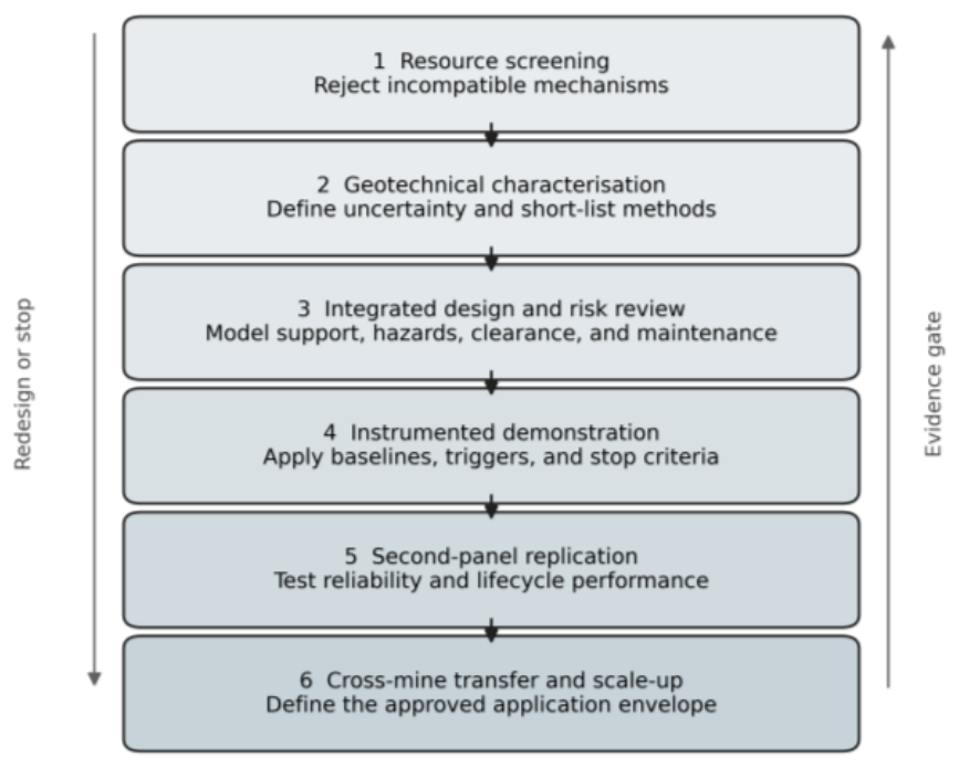
Six-Gate Boundaries and Intended Use
The six-gate framework is a conceptual assurance architecture rather than a design code or a statutory standard. It organizes decision-making from the first resource screening to cross-mine transfer using a consistent structure, rather than prescribing a single numerical limit.
Each gate has three possible outcomes.
- ▯
- Pass: The minimum evidence for that gate is met, and no essential mechanism fails.
- ▯
- Conditional hold: One or more requirements are not yet satisfied, but the gap can, in principle, be closed by defined investigations, redesigns, or monitoring. The project does not progress until these actions are completed and reviewed by the committee.
- ▯
- Stop: An essential mechanism is incompatible with the proposed method (e.g., non-cavable coal for LTCC, an unsustainable floor factor for HR-SPL, or the inability to meet statutory gas or support limits). A stop decision cannot be offset by high expected production, favorable economics, or other attractive scores.
The quantitative values in Table 5 are proposed review minima for a structured demonstration and not universal safety guarantees or legal limits. They are assembled from heterogeneous case evidence, numerical studies, and normative engineering judgments, and must be
- ▯
- The limits were replaced or tightened wherever legislation, approved support rules, or site-specific calibration required more conservative limits.
- ▯
- Recalibrated instrumented demonstrations, replications, and cross-block applications generated improved data.
The intended use is as follows:
- ▯
- For operators and designers, the gates provide a checklist of minimum evidence sets (data, models, monitoring, and reports) that must exist before a thick-seam technology can progress from pre-feasibility to demonstration and then to broader deployment phases.
- ▯
- For independent reviewers and regulators, the gates provide a transparent structure for judging whether a proposal has satisfied geology, geomechanics, hazard, operational, economic, and transfer tests in sequence, without allowing multi-criteria scoring to “average away” a failed physical constraint.
- ▯
- For policy and research planning, the gates identify where current Indian evidence is strong (e.g., geomechanics for certain longwalls and CM experience) and where it is weak (e.g., LTCC field demonstration and replication) so that demonstration projects and monitoring programs can be targeted.
In practice, the framework should be applied as an evidence-to-decision pathway: methods that fail Gates 1 and 2 on basic geometry and geomechanics are excluded before optimization; Gates 3 and 4 then test whether an integrated design works under instrumented field conditions; and Gates 5 and 6 determine whether the performance is reproducible within and across mines. No additive score, economic benefit, or qualitative assurance should override a failed result.
This sequence is supported by the historical evidence. Variable blasting-gallery caving and fire performance support early geological and integrated hazard gates 1–3. The instrumented East Katras trial demonstrated why Gate 4 must measure the support–strata response to maintain stability. The multislice complexity and uneven blasting-gallery continuity justify the second-panel gate 5. The incomplete transfer of imported high-capacity systems motivates the independent cross-block Gate 6. Table 6 maps these lessons, technology by technology.
5.3. Sensitivity Test of the Framework
Worked scenario. Consider an 8.0 m seam with a 400 m cover height. A 3.5 m lower cut leaves a 4.5 m top coal. Using RMR = 40 and coal UCS = 15 MPa in the published FTCD equation yields 5.29 m of coal. Across a plausible uncertainty set—EH 3.5 m, TC 4–5 m, RMR 34–50, UCS 12–20 MPa, and H 350–500 m—the predicted FTCD spanned approximately 2.96–7.80 m. Therefore, the decision is not ‘LTCC passes at 5.29 m’; Stage 2 is conditional, the installation/no-draw monitoring length uses the adverse upper estimate, and Stage 3 must test the fracture network and pre-conditioning scenarios.
The same block illustrates the sensitivity of the proposed method. A CM with a 4.6 m repeatable cut leaves 3.4 m; therefore, it fails a full-height-recovery objective, although it may remain a viable lower-seam option. A 5.5 m HR-SPL leaves 2.5 m and progresses only if partial recovery is acceptable, or another recovery mechanism is justified. It must separately pass the 1.5 floor factor and support load margin. The LTCC passes the geometric screen but remains conditional until the TCCR/COSFLOW, gas, fire, dilution, and rear-AFC capacities are satisfied. If one stop criterion is partly met, such as the predicted support load at 86% of yield against an 85% gate, the project holds for resizing or uncertainty reduction; it is not averaged with an attractive output.
Worked Example (Hypothetical): A 7–9 M Seam Block Through All Six Gates
Consider a Gondwana seam with a thickness varying from 7 to 9 m over the proposed first-panel footprint at depths of 350–450 m. Exploration has provided five core boreholes within the block and three on its periphery. After geostatistical modelling, the 7–9 m seam was reduced to a 7.3–8.6 m P10–P90 range over the first 250 m of retreat, with no design point more than 400 m from a logged core and all faults ≥ 1 m throw mapped from a combination of drilling, 3D seismic and legacy plans. The thickness uncertainty (P90 − P10)/P50 was approximately 17%. Stage 1 therefore passes for an LTCC candidate block, whereas a high-reach single-pass longwall (HR-SPL) is geometry-limited to a 5.5–6.0 m cut and would leave 1.3–3.1 m of roof coal.
In Stage 2 (geotechnical characterisation), laboratory tests yielded mean UCS values of 14–18 MPa for coal, 28–35 MPa for the immediate roof, and 22–28 MPa for the floor, with at least ten valid tests per unit and coefficients of variation of 0.15 and 0.25, respe ctively. The oriented televiewer and roadway mapping identified two dominant discontinuity sets in the top coal, with a mean spacing in the 0.6–1.2 m range and a CMRI–ISM rock mass rating for the top coal between 38 and 46. Floor shear strength tests, combined with a shield-base pressure envelope for the candidate LTCC and HR-SPL supports, showed a floor-bearing factor of safety of ≥1.6 at the 95th-percentile base pressure and ≥1.3 under an adverse stress-rotation scenario. Using these inputs in a TCCR-based cavability screen yields an overall TCCR Class II–III with a modelled top-coal recovery envelope centered near 75–80%, whereas an FTCD calculation across plausible EH (3.2–3.6 m), TC (4.0–5.0 m), RMR (38–46), UCS (14–18 MPa), and depth (350–450 m) combinations produces a 3.0–7.5 m range with a nominal central estimate of approximately 5 m. Therefore, the LTCC passes Stage 2 conditionally: cavability is in the preferred II–III band, but the upper FTCD bound is used to set a conservative no-draw installation length. HR-SPL can pass Stage 2 only if the floor factor and shield-load margins remain acceptable at the proposed 5.5–6.0 m height, and a CM system can pass for a 3.0–3.5 m cut but fails any full-height recovery objective.
At Stage 3 (integrated design), three-dimensional geomechanical models are calibrated against either an adjacent longwall panel or instrumented development headings, with target errors ≤ 20% for convergence, support loads, and caving intervals in the analog. P10/P50/P90 combinations of seam thickness, top-coal RMR, coal UCS, banded stone, and stress were used for both the LTCC and HR-SPL concepts. For LTCC, scenarios include variations in fracture stiffness and friction angle to test for early massive falls (safety-critical) versus incomplete top-coal recovery (economic but non-fatal). For HR-SPL, scenarios explore weak floor lenses and stone band interceptions that could trigger shield rotation, rib spalling or gate-road overstressing. In parallel, ventilation and gas models confirmed that the proposed panel can carry the designed methane emissions, dust, and heat loads with statutory margins, including the additional disturbance of the LTCC drawing at the rear of the AFC system. A design review with independent participation signs off that no scenario within the declared uncertainty set drives shield loads above 85% of the yield, reduces the floor safety factor below 1.5, or produces goaf or face conditions that violate gas, dust, or convergence-triggering limits. Under these conditions, LTCC progresses to Stage 4 as the only method capable of credible full-height recovery, whereas HR-SPL is either abandoned for this block or retained as a partial-recovery lower-seam option with a separately documented residual coal liability.
In Stage 4 (instrumented demonstration), a 200 m face and 1200 m retreat length were approved. The first 60–80 m were advanced without top-coal drawing to confirm the shield pressure response, caving behavior, and strata convergence. The observed main weighting intervals and convergence slopes were compared to Stage 3 predictions; if they remained within the calibrated bands, controlled drawing was started with a 1.0–1.5 m effective opening height and a conservative draw interval. Instrumentation includes shield-pressure transducers on every second unit, leg-closure and tilt sensors, gate-road extensometers, microseismic monitoring where warranted, rear-AFC load cells, ventilation and pressure surveys, continuous methane and CO monitoring at the face, tailgate, and rear AFC, and routine dust and ash sampling. Over the first 100–150 m of drawing, the demonstration meets or exceeds the provisional targets: in-situ recovery ≥ 75%, top-coal recovery ≥ 70%, dilution ≤ 15% by mass in the saleable product, mechanical availability ≥ 75%, and 95th-percentile support loads below 80–85% of yield, with all statutory environmental and occupational exposures within limits. A shortfall in a non-safety metric—for example, a 65% top-coal recovery with acceptable safety performance—triggers a conditional hold, additional draw-geometry and fragmentation analysis, and a repeated bounded trial, rather than a silent normalization.
In Stage 5 (replication), a second LTCC panel is driven in the same block with the same reporting definitions for reserve, recovery denominator, dilution, availability, delays, support loads, gas and fire indicators, dust exposure, and cost per saleable tonne. If the second panel shows no unexplained > 10 pp deterioration in recovery or availability and no new safety-significant mechanism, the LTCC is regarded as locally mature for the 7–9 m seam domain in this mine. In contrast, if the second panel reveals, for example, increasing floor damage under a slightly thicker segment of the seam or a different stone band configuration, the method may remain approved but with a narrowed geological envelope and revised operating rules that must be followed by the miners.
In Stage 6 (transfer and scale-up), the operator proposes to apply LTCC to a second 7–9 m seam block in another mine, again at approximately 350–450 m depth, but with a stiffer immediate roof and more pronounced stone bands. The geological model, geotechnical test program, TCCR/FTCD assessment, coupled geomechanical and ventilation models, and hazard controls are repeated rather than assumed to be transferable. The approving authority requires a fresh demonstration plan with pre-declared success, conditional-hold and stop criteria, and an explicit comparison with the first mine’s operating envelope. Only after the second mine has completed at least one fully instrumented panel, with comparable recovery, dilution, availability, and safety performance, does the LTCC qualify as a scalable national option for 7–9 m seams within the defined RMR, stress, floor, and gas bounds. HR-SPL and CM remain the preferred options in other geological domains but are no longer assumed to close the full-height recovery gap in this thickness range without a similar gate-by-gate demonstration.
5.4. Comparison of Indian Technology Maturity
The Indian experience is best understood as a portfolio rather than linear replacement (Table 6). Conventional and mechanized bord-and-pillar systems are necessary for irregular and legacy reserves in the coal mining industry. HR-SPL is appropriate for selected continuous block sets. In some settings, the LTCC may address part of the vertical recovery gap left by both systems, but only if its cavability and rear-face hazards are first demonstrated and independently validated under Indian conditions; currently, this remains a hypothesis rather than an established outcome.
6. Why Technologies Succeed, Stall, or Disappear
6.1. Compatibility Is More Important than Nominal Capacity
Indian records repeatedly show that equipment capacity is a necessary but insufficient condition for good performance. The longwall output depends on stable gate roads, face continuity, caving, coal clearance, and rapid repair. The CM output depends on the balance among cutting, bolting, haulage, ventilation, and support movement. BG recovery depends on a combination of coal fragmentation, remote loading, roof caving, and fire management. The LTCC depends on the coupled response of the lower face, top coal, roof, shield, rear AFC and ventilation systems. Therefore, a technology can be technically capable but systemically incompatible with the mine.
Geology should be treated as an uncertain, rather than a fixed, input. Borehole spacing can conceal local stone bands, rolls, faults, weak floor zones, and roof-channel sandstones. A deterministic design based on average properties may fail when the tails of the distribution control the performance. Geostatistical seam models, uncertainty envelopes, sensitivity analyses, and observational updates during development provide a strong basis for this. The objective is not to eliminate uncertainty before mining—an impossible standard—but to identify which uncertainties can trigger different failure mechanisms and to monitor them accordingly.
6.2. Production Continuity and Maintainability
The peak output is often the most visible performance measure; however, continuity is crucial for the commercial viability. A high-capacity system has a dense chain of dependencies, and the failure of the weakest component prevents the entire system from functioning appropriately. The history of longwall mining in India demonstrates the importance of spare parts, overhaul capacity, gate road conditions, face transfer, and original equipment support (OES). CM systems add fleet coordination, cable and shuttle car management, and bolting capacity to mining processes. BG added cyclic blasting and fume clearance to their model. Technologies should be compared based on their availability, utilization, retreat rate, planned and unplanned delays, maintenance hours, panel completion time and face transfer duration.
Discontinuation should not be automatically labelled as a technical failure. Reserve exhaustion, mine closure, opencast conversion, corporate standardization, withdrawal of vendor support, workforce changes, and competing capital priorities can end a method that is technically feasible. Conversely, repeated use does not prove optimal recovery if favorable short-term production masks sterilized roofs or residual pillars. Future case reporting should separate the reasons for panel cessation, mine-level discontinuation, and organization-level technology selection.
6.3. Safety and Regulatory Learning
The safe operating envelope of a new method should be expressed in terms of performance requirements and trigger levels rather than as a fixed equipment specification. The key indicators include support pressure and convergence, roof separation, rib deformation, floor heave, methane and carbon monoxide levels, airflow, dust exposure, water balance, machine proximity events, and deviations from the extraction sequence. Trigger-action-response plans must state who receives the information, who may stop production, and what evidence is required to restart the process.
Table 7 shows why controls cannot be assigned to hazards independently. For example, increasing the face advance rate may reduce spontaneous heating exposure while increasing the methane and coal clearance demand. Induced caving can reduce dangerous roof overhangs but can disturb ventilation or increase gas emissions. Water injection can suppress dust or improve fragmentation while degrading the weak floor or changing its permeability. Therefore, integrated design reviews must evaluate the interactions and unintended consequences.
6.4. Technology Transfer as System Adaptation
Successful transfer requires adaptation at three linked levels: The physical system includes the equipment geometry, support, haulage, power, ventilation, and monitoring. The operating system includes maintenance, logistics, production rules, competencies, and emergency responses. The governance system includes design review, change control, reporting definitions, stop authority, and learning across the panels. This is consistent with sociotechnical transition theory, in which technologies co-evolve with user practices, infrastructure, institutions, and rules, rather than diffusing as isolated artifacts [80,81]. In mining, automation also changes the workload, situational awareness, trust, task identity, employment, and community relations [83]. Therefore, importing only the machine transfers nominal capacity but not a functioning sociotechnical system.
This interpretation explains why historical technologies remain useful. BG contributes knowledge on remote recovery and induced caving. MSLM contributes to the understanding of interslice interaction and artificial roofs. East Katras contributes support–strata observations under top-coal caving. Hydraulic mining contributes to remote breakage and closed-loop material transport. CM research contributes to proximity protection and rib/snook design. HR-SPL contributes to face alignment, shield control, and system-capacity matching. Although the future system may be novel, many of its failure mechanisms have already been observed in other systems.
6.5. Economics, Automation and Broader Impact
Comparable capital and operating costs are the weakest pieces of quantitative evidence in this study. The currency year, local content, development scope, financing, rehabilitation, vendor support, and recovery denominators differ significantly in establishing a universal cost-per-tonne ranking. The author’s parametric case [63] reported an LTCC internal rate of return of 30.24% versus 18% for single-pass longwall under assumed 70% top-coal recovery, 85% performance, 20% cost increment, and a two-grade product penalty. This is scenario evidence and not an investment benchmark. Therefore, every Stage 3 case should report the P10/P50/P90 NPV, IRR, and cost per saleable tonne, including the costs of development, equipment moves, gas drainage, inertization, water, subsidence compensation, closure, and carbon/methane sensitivity.
Automation readiness also differs according to the employed methods. CM systems can combine guidance, remote cutting, proximity intervention, and continuous haulage capabilities. HR-SPL can be used for automated horizon control, shield advancement, face alignment, and condition monitoring. LTCC additionally requires automated rear-door sequencing, coal–gangue discrimination, and rear AFC gas/dust sensing. BG, hydraulic, and descending-shield concepts benefit mainly from teleoperation, which removes personnel from blast or draw zones. Across all methods, reliable communication, interoperable sensing, degraded-mode procedures, change and cyber security controls, and clearly defined human overrides remain the minimum system requirements [32,33,83].
Broader impact assessments must extend beyond production costs. Thick-seam projects should quantify the predicted subsidence and receptors, groundwater drawdown and contamination pathways, methane captured, oxidized, and vented, energy and water per saleable tonne, dust, noise and vibration exposure, residual coal/fire liability, land requirements, and closure monitoring. Workforce assessments should report the roles removed from high-risk zones, new control and maintenance competencies, retraining requirements, contractor dependence, and local employment effects. Community engagement should begin before a demonstration, disclose uncertainty and compensation rules, and provide accessible grievance and monitoring mechanisms. These conditions link technology selection to environmental justice, occupational health ethics, and a managed energy transition, rather than treating “Ethics approval: not applicable” as an adequate ethical analysis. These indicators are proposed as reporting minima for demonstration, not as a complete ESG framework or a normative ethical approval test.
7. Research Priorities and an Indian Implementation Roadmap
7.1. A National Thick-Seam Characterisation Framework
India requires a searchable, source-traceable inventory of thick-seam blocks rather than a single national percentage of “thick-seam resources.” The inventory should record the seam thickness distribution, dip, depth, stone bands, coal and rock mass properties, roof cavability, floor bearing capacity, structures, legacy workings, hydrogeology, gas content and emission, spontaneous heating indices, surface constraints, and data confidence levels. This would allow the resource to be classified by a feasible extraction mechanism, rather than thickness alone.
Standardization is equally important in the project performance stage. Every demonstration should report the panel reserve, extraction denominator, dilution, product recovery, gate and barrier coal, face advance, operating hours, delays, support loading, gas and fire indicators, dust exposure, maintenance, capital and operating costs, and the reasons for cessation. In the absence of common definitions, cross-mining learning remains anecdotal.
7.2. Priority Research Questions
The first priority is coupled geomechanical research. The models should represent coal wall failure, roof caving, goaf compaction, support response, floor bearing, and stress transfer to the gate roads and legacy workings. Calibration must use field measurements rather than visual agreement alone [35,36,52,53,54,55,56,57,58,59]. Probabilistic or scenario-based results are preferable when the input uncertainty is high.
The second priority is to understand full-height recovery options beyond the reach of CM. When considering LTCC, candidate blocks can be ranked using laboratory fragmentation tests, discontinuity mapping, rock mass cavability assessment, numerical modelling, physical or particle flow experiments, and mine-scale gas and fire analysis [8,61,62,63,64,65,66,67,68,69,70,71,72]. Any future LTCC field trial, if pursued, should be designed as an experiment with pre-declared success, conditional hold, and stop criteria, rather than as a routine production installation.
The third priority is intelligent sensing and control. Machine navigation, shield pressure analytics, face imaging, coal–gangue discrimination, wireless convergence monitoring, methane and carbon monoxide networks, and predictive maintenance can reduce exposure and detect emerging instability [32,33,36]. Algorithms must remain auditable, fail-safe, and subordinate to the defined human authorities. The training data should include abnormal and interrupted conditions in addition to steady production.
The fourth priority is the life cycle evaluation of technology. Recovery, dilution, energy, water, emissions, surface impact, waste, occupational exposure, mine closure, and stranded equipment should be assessed over the panel and mine life. A method with a lower peak output may create greater value if it reduces the need for sterilization and provides more reliable results than current methods. Conversely, high in-situ recovery is not automatically preferable if dilution, fire loss, or prolonged delays erode saleable recovery and increase risk.
7.3. Proposed Demonstration Sequence
For seams within a defensible cutting envelope, India is likely to obtain the most immediate benefits by continuing to improve HR-SPL and CM systems through geological modelling, gate-road and residual-pillar design, automation, proximity intervention, dust control, and maintenance analytics. For seams beyond this envelope, LTCC currently appears to offer a plausible demonstration pathway because it directly targets the upper coal that might otherwise remain unexploited. However, this rationale is contingent on site-specific cavability, hazard control, monitoring capability, and institutional appetite for conducting high-consequence field experiments.
The first panel should provide a face width of at least 150 m and a retreat length of at least 1000 m, or demonstrate by calibrated modelling that a shorter geometry contains three main weighting cycles and ≥100 m of stable drawing. Instrumentation should include pressure on every shield (or a validated dense sample), leg closure and attitude, gate convergence/extensometers, face-spall mapping, microseismic monitoring where warranted, airflow and pressure surveys, continuous methane at the face/tailgate/rear AFC, CO and temperature in return/goaf monitoring points, personal and fixed dust sampling, rear-AFC mass flow, image/sensor-based coal–gangue indicators, product ash/dilution sampling, water balance, energy use, delay coding, and maintenance records. Establish ≥30 operating days of baseline, advance ≥ 50 m without top-coal drawing, and then draw under controlled rules for ≥100 m and ≥3 weight cycles before routine operation.
The progression targets were as follows: in situ recovery ≥ 75%, top-coal recovery ≥ 70%, dilution ≤ 15%, mechanical availability ≥ 75%, 95th-percentile support load < 85% of yield, floor factor ≥ 1.5, and all methane, dust, CO, ventilation, and occupational exposures within statutory and approved trigger-action-response limits. These are proposed demonstration targets and not substitutes for legal limits. Stop immediately for uncontrolled top-coal/roof fall, structural support damage, loss of rear-AFC ventilation or communication, or any statutory withdrawal trigger. A miss on a non-safety target causes a documented conditional hold, root cause analysis, and bounded repeat, not a silent average. The first weighting, stable drawing, 100 m, midpoint, and panel completion were reviewed, and at least one full panel plus 12 months of post-mining subsidence, gas/fire, and water monitoring before Stage 5 were retained for the analysis. Replication requires a second full panel and disclosure of face-transfer time, lifecycle costs, and all delay categories.
8. Conclusions
Underground thick-seam mining is not a contest to identify a universally superior technology. The decisive question is whether the extraction mechanism and complete operating system are compatible with the seam, surrounding strata, hazards, infrastructure, and organizational capabilities of the mine site. The only initial variable was the seam thickness. Continuity, coal mass structure, roof cavability, floor bearing, stress, stone bands, gas, spontaneous heating, water, surface constraints, panel geometry, coal clearance, maintenance, and workforce competence determine whether a method progresses from technical feasibility to sustainable performance.
India’s historical records support the following five conclusions: First, bord-and-pillar variants remain necessary for irregular and legacy reserves; however, full seam recovery is constrained by the height and residual support geometries. Second, continuous miners are the country’s most scalable mechanized underground system within bounded cutting and depillaring envelopes. Third, although high-reach single-pass longwalls can deliver strong performance in carefully selected continuous blocks, increasing the height magnifies the coal wall, shield, floor, and gate road requirements. Fourth, the blasting gallery, multislice, sublevel-caving, hydraulic, and descending-shield methods are best treated as valuable bodies of engineering evidence or niche options, not as automatically transferable historical solutions. Fifth, LTCC is a prominent candidate for any future demonstration addressing seams beyond the practical cutting height; however, its status in India remains entirely pre-demonstration, and currently, there is insufficient field evidence to support any claims of operational maturity or comparative advantage.
In doing so, this review delivers three main advances over earlier syntheses.
- ▯
- A structured six-gate assurance architecture that turns statutory scientific study, instrumented trials, replication, and cross-mine transfer into an explicit, non-compensatory sequence of decisions, instead of treating thick-seam approvals as one-off design events is proposed.
- ▯
- Source-graded performance envelopes for major methods, grounded in Indian and international thick-seam practice and explicitly labelled by evidence type (field, numerical, regulatory, expert), so that the proposed quantitative “gates” are transparently linked to the quality and origin of the underlying data.
- ▯
- A decision-oriented reading of the historical Indian experience, using past BG, CM, HR-SPL, longwall, and LTCC attempts, proposes minimum evidence sets and gate outcomes for any future technology demonstrations and possible scale-up, rather than presenting these cases only as a narrative.
- ▯
- A decision-oriented reading of the historical Indian experience, using past BG, CM, HR-SPL, longwall, and LTCC attempts to define minimum evidence sets and gate outcomes for future technology demonstrations and scale-up, rather than presenting these cases only as narratives.
The central policy implication is that India needs a national process for characterizing, selecting, demonstrating, and scaling mine-specific systems rather than a single national thick-seam method. Transparent recovery definitions, authoritative accident evidence, coupled hazard assessments, instrumented trials, independent reviews, and second-panel replications are the minimum conditions required for scaling-up. Technology transfer succeeds when equipment, geology, support, ventilation, coal clearance, maintenance, competencies, and governance are integrated into one system.
Author Contributions
Conceptualization, N.B.; methodology, N.B.; validation, N.B.; formal analysis, N.B.; investigation, N.B.; resources, N.B.; data curation, N.B.; writing—original draft preparation, N.B.; writing—review and editing, N.B.; visualization, N.B.; project administration, N.B. The author has read and agreed to the published version of the manuscript.
Funding
This research did not receive any external funding.
Institutional Review Board Statement
Not applicable because this study is a review of published and publicly available technical evidence and does not involve human participants or animals.
Informed Consent Statement
Not applicable.
Data Availability Statement
No new datasets were created in this study. The evidence supporting the synthesis is contained in the cited literature, and the claim-to-source audit is presented in Table 4 below. Mine-specific applications require geological, operational, and monitoring data that are subject to the owners’ access conditions.
Acknowledgments
Paperpal was used for grammar and language refinement, and ChatGPT (OpenAI) was used for editorial restructuring, consistency checking, and document formatting support during revision. The author has reviewed and edited all outputs and takes full responsibility for the manuscript. No AI tool was used to generate, alter, or analyze primary data.
Conflicts of Interest
The author declares no conflict of interest.
Appendix A. Practitioner Implementation Checklist
- ▯
- The total seam thickness, candidate cutting height, and residual thickness Δt were defined, and the recovery denominator was then calculated.
- ▯
- Confirm core/logging coverage, uncertainty metrics, structures, legacy work, hydrogeology, and surface receptors.
- ▯
- Report coal/roof/floor test counts, distributions, discontinuity sets, stress, lower confidence bounds and upper confidence bounds.
- ▯
- For LTCC, the TCCR class and FTCD uncertainty were calculated; for HR-SPL, the floor factor and support margin were verified; and for CM, cutting/pick-wear and layout trials were performed.
- ▯
- Calibrate geomechanical, ventilation, gas, and fire models to field or analog observations and test adverse scenarios.
- ▯
- Coal clearance, ventilation, drainage, inertization, water, power, spares, and maintenance for the same production cases were also considered.
- ▯
- Predeclare success, conditional hold, and stop criteria, and identify independent stop authority, and restart evidence.
- ▯
- Establish baseline and instrument support, strata, gas, CO, dust, dilution, energy, water, delays, and costs.
- ▯
- The report panel, saleable recovery, availability, utilization, delay distribution, and face-transfer durations were also analyzed.
- ▯
- Evaluate P10/P50/P90 NPV/IRR/cost per saleable tonne, methane/carbon sensitivity, and closure liabilities.
- ▯
- Complete workforce skills, automation human factors, and emergency, community, subsidence, and water impact plans.
- ▯
- Requires second-panel replication and cross-block verification before claiming scalability.
References
- Ministry of Coal; Government of India. Technology Roadmap for the Coal Sector; Ministry of Coal: New Delhi, India, 2021. Available online: https://coal.gov.in/techno-roadmap-coal-sector (accessed on 9 August 2026).
- Central Mine Planning and Design Institute Limited. 50th Annual Report and Accounts 2024–2025; CMPDI: Ranchi, India, 2025; Available online: https://www.cmpdi.co.in/sites/default/files/2025-08/50th%20Annual%20Report%20of%20CMPDIL%20for%20the%20FY%202024-25.pdf (accessed on 9 August 2026).
- Singh, R.D. Principles and Practices of Modern Coal Mining; New Age International: New Delhi, India, 1998. [Google Scholar]
- Ghose, A.K. Underground methods of extraction of thick coal seams—A global survey. Min. Sci. Technol. 1984, 2, 17–32. [Google Scholar] [CrossRef]
- Central Mining Research Station. Proceedings of the International Symposium on Thick Seam Mining: Problems and Issues, Dhanbad, India, 19–21 November 1992; CMRS: Dhanbad, India, 1992. [Google Scholar]
- Wang, J. Development and prospect on fully mechanized mining in Chinese coal mines. Int. J. Coal Sci. Technol. 2014, 1, 253–260. [Google Scholar] [CrossRef]
- Wang, J.; Wang, Z. Systematic principles of surrounding-rock control in longwall mining within thick coal seams. Int. J. Min. Sci. Technol. 2019, 29, 65–71. [Google Scholar] [CrossRef]
- Le, T.D.; Oh, J.; Hebblewhite, B.; Zhang, C.; Mitra, R. A review of cavability evaluation in longwall top coal caving. Int. J. Min. Sci. Technol. 2017, 27, 907–915. [Google Scholar] [CrossRef]
- Jangara, H.; Ozturk, C.A. Longwall top coal caving design for thick coal seam in very poor strength surrounding strata. Int. J. Coal Sci. Technol. 2021, 8, 641–658. [Google Scholar] [CrossRef]
- Page, M.J.; McKenzie, J.E.; Bossuyt, P.M.; et al. The PRISMA 2020 statement: An updated guideline for reporting systematic reviews. BMJ 2021, 372, n71. [Google Scholar] [CrossRef] [PubMed]
- Tyndall, J. AACODS Checklist; Flinders University: Adelaide, Australia, 2010; Available online: https://fac.flinders.edu.au/dspace/api/core/bitstreams/e94a96eb-0334-4300-8880-c836d4d9a676/content (accessed on 9 August 2026).
- Sheorey, P.R.; Das, M.N.; Barat, D.; Prasad, R.K.; Singh, B. Coal pillar strength estimation from failed and stable cases. Int. J. Rock Mech. Min. Sci. Geomech. Abstr. 1987, 24, 347–355. [Google Scholar] [CrossRef]
- Sheorey, P.R. A theory for in situ stresses in isotropic and transversely isotropic rocks. Int. J. Rock Mech. Min. Sci. Geomech. Abstr. 1994, 31, 23–34. [Google Scholar] [CrossRef]
- Singh, R.; Mandal, P.K.; Singh, A.K.; Singh, T.N. Cable bolting based mechanised depillaring of a thick coal seam. Int. J. Rock Mech. Min. Sci. 2001, 38, 245–257. [Google Scholar] [CrossRef]
- Singh, R.; Sheorey, P.R.; Singh, D.P. Stability of the parting between coal-pillar workings in level contiguous seams during depillaring. Int. J. Rock Mech. Min. Sci. 2002, 39, 9–39. [Google Scholar] [CrossRef]
- Singh, R.; Ram, S.; Singh, A.K.; Prasad, S.; Buragohain, J. Underground extraction of contiguous coal seams/sections consisting of thin parting: A case study. J. S. Afr. Inst. Min. Metall. 2004, 104, 17–27. [Google Scholar]
- Mandal, P.K.; Singh, R.; Maiti, J.; Singh, A.K.; Kumar, R.; Sinha, A. Underpinning-based simultaneous extraction of contiguous sections of a thick coal seam under weak and laminated parting. Int. J. Rock Mech. Min. Sci. 2008, 45, 11–28. [Google Scholar] [CrossRef]
- Singh, R.; Mandal, P.K.; Singh, A.K.; Kumar, R.; Maiti, J.; Ghosh, A.K. Upshot of strata movement during underground mining of a thick coal seam below hilly terrain. Int. J. Rock Mech. Min. Sci. 2008, 45, 29–46. [Google Scholar] [CrossRef]
- Singh, R.; Mandal, P.K.; Singh, A.K.; Kumar, R.; Sinha, A. Optimal underground extraction of coal at shallow cover beneath surface/subsurface objects: Indian practices. Rock Mech. Rock Eng. 2008, 41, 421–444. [Google Scholar] [CrossRef]
- Singh, R.; Singh, A.K.; Maiti, J.; Mandal, P.K.; Singh, R.; Kumar, R. An observational approach for assessment of dynamic loading during underground coal-pillar extraction. Int. J. Rock Mech. Min. Sci. 2011, 48, 794–804. [Google Scholar] [CrossRef]
- Kumar, R.; Mishra, A.K.; Singh, A.K.; Singh, A.K.; Ram, S.; Singh, R. Depillaring of total thickness of a thick coal seam in single lift using cable bolts: A case study. Int. J. Min. Sci. Technol. 2016, 26, 223–233. [Google Scholar] [CrossRef]
- Banerjee, S.C. Prevention and Combating of Mine Fires; Oxford & IBH Publishing: New Delhi, India, 2000. [Google Scholar]
- Singh, R.V.K. Spontaneous Heating and Fire in Coal Mines; CRC Press: Boca Raton, FL, USA, 2013. [Google Scholar] [CrossRef]
- Directorate General of Mines Safety. Technical Circular No. 4 of 2018: Guidelines for Determination of Incubation Period of Coal Seams; DGMS: Dhanbad, India, 2018. [Google Scholar]
- Directorate General of Mines Safety. Major Accidents in Indian Coal Mines, 1952–2005; DGMS: Dhanbad, India, 2005. [Google Scholar]
- Mangal, A.; Paul, P.S.; Dash, A.K.; Bhattacharjee, R.M. Role of convergence behaviour for superior recovery of thick coal seams in underground mines by blasting gallery. J. Mines Met. Fuels 2016, 64, 63–73. [Google Scholar]
- Singh, R. Staggered development of a thick coal seam for full-height working in a single lift by the blasting-gallery method. Int. J. Rock Mech. Min. Sci. 2004, 41, 745–759. [Google Scholar] [CrossRef]
- Sawmliana, C.; Pal Roy, P. A new blastability index for hard roof management in blasting gallery method. Geotech. Geol. Eng. 2012, 30, 1357–1367. [Google Scholar] [CrossRef]
- CSIR–Central Institute of Mining and Fuel Research. Annual Report 2014–2015; CSIR-CIMFR: Dhanbad, India, 2015. [Google Scholar]
- Kushwaha, A.; Bhattacharjee, R.; Tewari, S.; Sinha, A. Extraction of locked-up coal in standing pillars in Indian underground coal mines. J. Rock Mech. Tunn. Technol. 2015, 21, 115–129. [Google Scholar]
- Singareni Collieries Company Limited. Revised Mining Plan and Mine Closure Plan of Vakilpalli Mine; SCCL: Kothagudem, Telangana, 2018. [Google Scholar]
- National Institute for Occupational Safety and Health. Accurate Navigation and Control of Continuous Mining Machines for Coal Mining; DHHS (NIOSH) Publication 98-101: Pittsburgh, PA, USA, 1997. [Google Scholar]
- Jobes, C.C.; Carr, J.L.; DuCarme, J.P. A New Visual Warning System to Reduce Struck-by or Pinning Accidents Involving Continuous Mining Machines; DHHS (NIOSH) Publication 2013-151: Pittsburgh, PA, USA, 2013. [Google Scholar]
- National Institute for Occupational Safety and Health. Best Practices for Dust Control in Coal Mining, 2nd ed.; DHHS (NIOSH) Publication 2021-119: Pittsburgh, PA, USA, 2021. [Google Scholar] [CrossRef]
- Singh, R.; Kumar, A.; Singh, A.K.; Coggan, J.; Ram, S. Rib/snook design in mechanised depillaring of rectangular/square pillars. Int. J. Rock Mech. Min. Sci. 2016, 84, 119–129. [Google Scholar] [CrossRef]
- Vinay, L.S.; et al. Machine learning approach for prediction of mining-induced stress in underground mines to mitigate ground-control disasters and accidents. Geomech. Geophys Geo-Energy Geo-Resour. 2024, 10. [Google Scholar] [CrossRef]
- Mandal, P.K.; Bhattacharjee, R.; Ghosh, N.; Singh, A.P.; Tewari, S.; Das, A.J. Bridging efficiency and safety: Extraction of a thick coal seam having low incubation period using continuous miner. In Proceedings of the 10th Asian Mining Congress 2023; Springer: Cham, Switzerland, 2023; pp. 110–129. [Google Scholar] [CrossRef]
- Oitto, R.H.; et al. Methods for Thick Coal Seams in the Western United States; US Bureau of Mines: Washington, DC, USA, 1979. [Google Scholar]
- Boreck, D.L.; Clarke, D.R.; Hackett, T.D. Multislice Mining for Thick Western Coal Seams; US Bureau of Mines Information Circular: Washington, DC, USA, 1990. [Google Scholar]
- Morsy, K.; Peng, S.S.; Zhang, Y. Numerical modelling of the gob loading mechanism in longwall coal mines. In Proceedings of the 21st International Conference on Ground Control in Mining, Morgantown, WV, USA, 6–8 August 2002. [Google Scholar]
- Wang, P.; Zhao, J.; Feng, G.; Wang, Z. Interaction between vertical stress distribution within the goaf and surrounding rock mass in longwall panel systems. J. S. Afr. Inst. Min. Metall. 2018, 118, 745–756. [Google Scholar] [CrossRef]
- Singh, T.N. Soutirage—A dream mining method of thick coal seams. Trans. Min. Geol. Metall. Inst. India 1988, 85, 88–110. [Google Scholar]
- Smart, B.G.D.; Aziz, N.I. The influence of caving mechanism on powered-support rating. AusIMM Bull. Proc. 1989, 294, 77–84. [Google Scholar]
- Singh, R.; Singh, T.N. Investigation into the behaviour of a support system and roof strata during sublevel caving of a thick coal seam. Geotech. Geol. Eng. 1999, 17, 21–35. [Google Scholar] [CrossRef]
- Singh, R.; Kushwaha, A.; Singh, T.N. Geotechnical evaluation of a mechanised longwall-soutirage face. Minetech 1993, 14, 42–45. [Google Scholar]
- Singh, T.N. A Study of the Behaviour of Ground Due to Mining of Thick Coal Seams by Equivalent-Material Mine Modelling. Ph.D. Dissertation, Indian School of Mines, Dhanbad, India, 1982. [Google Scholar]
- Das, T.K.; Singh, T.N. Hydraulic mining at Gopalichak Colliery of Jharia Coalfield. J. Mines Met. Fuels 1995, 43, 7–16. [Google Scholar]
- Cooley, W.C. Survey of Underground Hydraulic Coal Mining Technology, Volume 1: Final Report; US Bureau of Mines: Washington, DC, USA, 1975; NTIS PB 251493. [Google Scholar]
- Read, R.G.; Tarter, J.H.; Smith, C.K.; Walter, R.P. Design of a Hydraulic-Jet Coal Miner; Report BRL/TR-74-7020; US Bureau of Mines Contract H0133052: Washington, DC, USA, 1974. [Google Scholar]
- Royal Commission on the Pike River Coal Mine Tragedy; Final Report; Government of New Zealand: Wellington, New Zealand, 2012; Volume 2, Part 2, Chapter 19.
- Adam, R.F.J.; Douglas, W.J. Assessment of the Single-Pass Thick-Seam Longwall Mining Method; US Bureau of Mines: Washington, DC, USA, 1982. [Google Scholar]
- Singh, G.S.P.; Singh, U.K. A numerical modelling approach for assessment of progressive caving and powered-support performance in longwall workings. Comput Geotech. 2009, 36, 1142–1156. [Google Scholar] [CrossRef]
- Singh, G.S.P.; Singh, U.K. Prediction of caving behaviour of strata and optimum rating of hydraulic powered support for longwall workings. Int. J. Rock Mech. Min. Sci. 2010, 47, 1–16. [Google Scholar] [CrossRef]
- Wang, J.; Yang, S.; Kong, D. Failure mechanism and control technology of longwall coalface in large-cutting-height mining. Int. J. Min. Sci. Technol. 2016, 26, 111–118. [Google Scholar] [CrossRef]
- Fu, Y.; et al. Movement of overlying strata in an ultra-large-mining-height face at Shangwan Coal Mine. Appl. Sci. 2024, 14, 4685. [Google Scholar] [CrossRef]
- Bai, Q.S.; Tu, S.H.; Chen, M.; Zhang, C. Numerical modelling of coal-wall spall in a longwall face. Int. J. Rock Mech. Min. Sci. 2016, 88, 242–253. [Google Scholar] [CrossRef]
- Kong, D.Z.; Cheng, Z.B.; Zheng, S.S. Failure mechanism and stability control in a large-cutting-height face with a deep-buried seam. Bull. Eng. Geol. Environ. 2019, 78, 6143–6157. [Google Scholar] [CrossRef]
- Behera, B.; Yadav, A.; Singh, G.S.P.; Sharma, S.K. Numerical modelling of geomechanical response in longwall operations under Indian conditions. Rock Mech. Rock Eng. 2020, 53, 1827–1856. [Google Scholar] [CrossRef]
- Trueman, R.; Lyman, G.; Cocker, A. Longwall roof control through understanding shield–strata interaction. Int. J. Rock Mech. Min. Sci. 2009, 46, 371–380. [Google Scholar] [CrossRef]
- Ramesh Kumar, B.; Chandrasekhar, S.; Veera Reddy, B. Construction and operation of high-capacity longwall project: Adriyala experience. In Recent Advances in Rock Engineering; Atlantis Press: Dordrecht, The Netherlands, 2016; pp. 53–61. [Google Scholar] [CrossRef]
- Khanal, M.; Adhikary, D.; Balusu, R. Prefeasibility study—Geotechnical studies for introducing longwall top coal caving in Indian mines. J. Min. Sci. 2014, 50, 719–732. [Google Scholar] [CrossRef]
- Khanal, M.; Adhikary, D.; Balusu, R. Evaluation of mine-scale longwall top-coal caving parameters using continuum analysis. Min. Sci. Technol. 2011, 21, 787–796. [Google Scholar] [CrossRef]
- Balasubrahmanyam, N.; Budi, G. Techno-economic feasibility of the longwall top coal caving method based on the FTCD index: A parametric case study in India. Energies 2021, 14, 6115. [Google Scholar] [CrossRef]
- Balasubrahmanyam, N.; Budi, G. Critical aspects of longwall top coal caving for application in Indian geomining conditions. In Geotechnical Challenges in Mining, Tunnelling and Underground Infrastructures; Lecture Notes in Civil Engineering; Springer: Singapore, 2022; Volume 228, pp. 77–96. [Google Scholar] [CrossRef]
- Humphries, P.; Poulsen, B.; Ren, T. Longwall Top Coal Caving Application Assessment in Australia; ACARP Project C13018; CSIRO: Brisbane, Queensland, 2006. [Google Scholar]
- Cai, Y.; Hebblewhite, B.K.; Onder, U.; Xu, B.; Kelly, M.; Wright, B.; Kraemer, M. Application of Longwall Top Coal Caving to Australian Operations; CSIRO–ACARP Report C11040: Brisbane, Queensland, 2003. [Google Scholar]
- Alehossein, H.; Poulsen, B.A. Stress analysis of longwall top coal caving. Int. J. Rock Mech. Min. Sci. 2010, 47, 30–41. [Google Scholar] [CrossRef]
- Vakili, A.; Hebblewhite, B.K. A new cavability assessment criterion for longwall top coal caving. Int. J. Rock Mech. Min. Sci. 2010, 47, 1317–1329. [Google Scholar] [CrossRef]
- Yasitli, N.E.; Ünver, B. 3D numerical modelling of longwall mining with top-coal caving. Int. J. Rock Mech. Min. Sci. 2005, 42, 219–235. [Google Scholar] [CrossRef]
- Wang, J.; Zhang, J.; Song, Z.; Li, Z. Three-dimensional experimental study of loose top-coal drawing law for longwall top coal caving. J. Rock Mech. Geotech. Eng. 2015, 7, 318–326. [Google Scholar] [CrossRef]
- Ren, T.; Wang, Z.; Zhang, J. Improved dust management at a longwall top-coal-caving face: A computational fluid dynamics approach. Adv. Powder Technol. 2018, 29, 2368–2379. [Google Scholar]
- Wang, J.; Yu, B.; Kang, H.; et al. Key technologies and equipment for a fully mechanized top-coal caving operation with a large mining height at ultra-thick coal seams. Int. J. Coal Sci. Technol. 2015, 2, 97–161. [Google Scholar] [CrossRef]
- Klimenko, A.Y. Early ideas in underground coal gasification and their evolution. Energies 2009, 2, 456–476. [Google Scholar] [CrossRef]
- Bhutto, A.W.; Bazmi, A.A.; Zahedi, G. Underground coal gasification: From fundamentals to applications. Prog. Energy Combust. Sci. 2013, 39, 189–214. [Google Scholar] [CrossRef]
- Perkins, G. Underground coal gasification—Part I: Field demonstrations and process performance. Prog. Energy Combust. Sci. 2018, 67, 158–187. [Google Scholar] [CrossRef]
- Singan, A.; Ranade, V.V. Deployment of underground coal gasification in India. Curr. Sci. 2017, 113, 218–227. [Google Scholar] [CrossRef]
- Younger, P.L. Hydrogeological and geomechanical aspects of underground coal gasification and coupling to carbon capture and storage. Mine Water Environ. 2011, 30, 127–140. [Google Scholar] [CrossRef]
- Kumar, R.; Singh, A.K.; Mishra, A.K.; Singh, R. Underground mining of thick coal seams. Int. J. Min. Sci. Technol. 2015, 25, 885–896. [Google Scholar] [CrossRef]
- Le, T.D.; Dao, H.Q.; Vu, D.H.; Nguyen, A.T. Impact of discrete fracture characteristics on longwall top coal stability. Acta Montan Slovaca 2022, 27, 851–863. [Google Scholar] [CrossRef]
- Geels, F.W. Technological transitions as evolutionary reconfiguration processes: A multi-level perspective and a case study. Res. Policy 2002, 31, 1257–1274. [Google Scholar] [CrossRef]
- Markard, J.; Raven, R.; Truffer, B. Sustainability transitions: An emerging field of research and its prospects. Res. Policy 2012, 41, 955–967. [Google Scholar] [CrossRef]
- Government of India. India’s Long-Term Low-Carbon Development Strategy; Submitted to the United Nations Framework Convention on Climate Change: New Delhi, India, 2022; Available online: https://unfccc.int/sites/default/files/resource/India_LTLEDS.pdf (accessed on 9 August 2026).
- Codoceo-Contreras, L.; Rybak, N.; Hassall, M. Exploring the impacts of automation in the mining industry: A systematic review using natural language processing. Min. Technol. 2024, 133. [Google Scholar] [CrossRef]
- Murmu, S.; Budi, G. An overview on the successful implementation of longwall mining technology in Indian geo-mining condition—A case study. Int. Res. J. Eng. Technol. 2018, 5, 1132–1139. [Google Scholar]
- Ministry of Coal; Government of India. Section-Wise Consolidated Note: Coal Gasification, Coal Bed Methane and Coal Mine Methane; Ministry of Coal: New Delhi, India, 2023. Available online: https://coal.gov.in/sites/default/files/2021-01/Section_Wise_06072023.pdf (accessed on 9 August 2026).
Figure 1.
PRISMA-inspired evidence-selection flow for the structured critical review (not a fully PRISMA-compliant systematic review; limitations are described in Section 2.2).
Figure 1.
PRISMA-inspired evidence-selection flow for the structured critical review (not a fully PRISMA-compliant systematic review; limitations are described in Section 2.2).
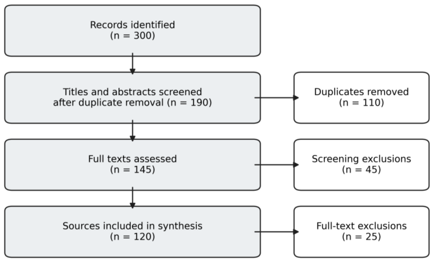
Table 1.
Quantitative LTCC cavability criteria and use in the proposed gates.
| Criterion | Published Quantitative Range | Meaning | Use in This Review | Source |
|---|---|---|---|---|
| TCCR Class I | MCD < 7 m; TCR > 100% | Very weak/excessive caving; >100% indicates roof material in the draw stream | Conditional: strengthen face-fall and dilution controls; do not auto-progress | [68] |
| TCCR Class II | MCD 7–15 m; TCR 79–100% | Good cavability | Progress if gas, fire, roof and floor gates also pass | [68] |
| TCCR Class III | MCD 15–23 m; TCR 59–79% | Fair cavability | Conditional progress; require calibrated draw/recovery model and target TCR ≥ 70% | [68] |
| TCCR Class IV | MCD 23–32 m; TCR 39–59% | Poor cavability | Hold/reject unless preconditioning is modelled, trialled and reclassified | [68] |
| TCCR Class V | MCD > 32 m; TCR < 39% | Very poor cavability | Reject conventional LTCC concept; reassess extraction mechanism | [68] |
| Khanal COSFLOW | Mine-specific properties, stress, geometry and support; no universal cut-off | Indian SCCL prefeasibility and mine-scale response | Use to calibrate support/caving scenarios and uncertainty; not as a stand-alone pass score | [61,62] |
| FTCD | Regression shown in text; examples in [63] produced ~3–8 m for varied top-coal thickness | Initial full-thickness caving distance | Set installation-room/no-draw monitoring length from upper confidence estimate | [63,64] |
| Coal UCS flag | ~25 MPa indicative upper reference; not universal | Intact-strength screen | Above value: require joint-resolved modelling and fragmentation/preconditioning trials | [78] |
| Discrete-fracture sensitivity | Orientation 45–135°: model TCR 60.35–92.16%; density 0.5–2 m/m2: TCR 60.35–68.55% | Joint geometry can outweigh intact strength | Measure orientation/density distributions and model adverse tails | [79] |
Table 2.
Selected numerical-modelling results relevant to thick-seam selection.
| Study Group | Reported Model/Case Result | Mechanism | Decision Use | Source |
|---|---|---|---|---|
| Indian longwall caving/support | 23 Indian case histories used in validation; convergence-rate criterion ~75 mm per metre of face advance | Support demand and progressive caving | Use convergence slope as an observational warning reference, then calibrate to site | [52,53] |
| Coal-wall spall | Modelled peak vertical stress 38.5 MPa about 3.2 m ahead of the face; steep reduction within ~1 m | High-face spall and sprag demand | Instrument the near-face stress/spall zone; do not equate peak model stress with UCS | [56] |
| Deep large-height face | Case geometry included ~860 m depth, 300 m face width and >1000 m panel length | Depth/width amplify gate and face response | Test depth, width, defects and support capacity jointly | [57] |
| Indian longwall geomechanics | Calibrated numerical studies reproduce progressive caving and support response under Indian strata | Support–strata interaction | Require quantitative error against field pressure/convergence histories | [58] |
| LTCC discrete fractures | Fracture stiffness 1→20 GPa/m reduced model TCR 68.34→59.02%; friction angle 5→35° reduced TCR 71.00→57.93% | Stronger/stiffer joints impede draw | Use distributions, not mean UCS alone | [79] |
| LTCC depth/material | Coal modulus 0.61→3.64 GPa reduced TCR 67.37→61.56%; depth 100→400 m increased pre-support top-coal fall 1.45→53.70% | Cavability and face fall are distinct outcomes | Model both ahead-of-support fall and behind-support recovery | [79] |
| Indian LTCC mine-scale | Continuum scenarios evaluated caving, support loading and panel geometry for an SCCL block | Indian prefeasibility | Recalibrate with new boreholes and development observations before procurement | [61,62] |
Table 3.
(A) Quantitative performance envelope of principal thick-seam methods. (B) Equipment, geometry, automation and economic evidence.
Table 3.
(A) Quantitative performance envelope of principal thick-seam methods. (B) Equipment, geometry, automation and economic evidence.
| (A) | ||||
| Method | Seam/Cutting Range | Reported Recovery | Reported Output | Evidence/Caveat |
| Bord-and-pillar variants | ~1.5–4.8 m mechanical cut; special induced-caving variants to ~10–12 m total | ~40–85% in selected development/depillaring cases; denominator varies | ~0.5–3 kt/d (case dependent) | Indian cases [3,14,19,21,78] |
| Blasting gallery | ~6–12 m seam; ~2.4–3.0 m floor galleries | ~70–85% selected favourable panels | ~0.5–0.9 kt/d favourable periods | Indian mine reports [26,27,28,29,30,31]; not sustained series |
| Continuous miner | ~1.4–4.6 m machine envelope | ~50–70%; selected pillar-extraction reports ~65–70% | ~1.5–3.0 kt/d Indian planning/case range | [1,2,35,37]; layout and delay dependent |
| Multislice longwall | ~2–3.5 m per slice; ~6–15 m total | ~70–90% in selected international/historical cases | ~0.5–3.0 kt/d; Indian series not comparable | [4,38,39,40,41] |
| Longwall sublevel caving | ~2.5–3.0 m lower cut plus top coal; East Katras ~7.5 m seam | ~60–80% experimental/case range | Generally <2 kt/d in historical evidence | [42,43,44,45,46]; experimental |
| Hydraulic mining | Gopalichak ~7.5 m seam; 80-bar monitor | Not consistently reported on comparable basis | Not consistently reported | [47,48,49,50]; experimental |
| Descending shield | Steep seams, commonly >40° dip | Not consistently reported | Not consistently reported | [3,4]; historical trial evidence |
| HR-SPL | ~4.5–6 m established range; ~6–8.8 m international leading edge | ~80–95% face/panel recovery in sui continuous blocks | India peaks ~8.5–13.2 kt/d; international high-capacity faces ~15–30 kt/d | [6,7,54,55,56,57,58,59,60,84] |
| LTCC | ~2.5–5 m lower cut; ~6–20+ m total seam | ~70–90%; drawing and dilution dependent | ~15–20 kt/d reported Chinese average; >5 Mt/y leading faces | [65,66,72]; no Indian production face |
| (B) | ||||
| Method Group | Support-Capacity Indication | Typical Panel Geometry | Automation/Remote Operation | Economic Evidence |
| Bord-and-pillar/BG | No longwall shield; MRS where mechanised pillar extraction | Short/irregular panels; geometry mine-specific | Remote LHD, proximity protection, mechanised bolting | Low–moderate capital; cost/t highly site-specific |
| Continuous miner | MRS rating project-specific; cutter/bolter support system | Panels/districts governed by inherited pillars and ventilation | Remote cutting, guidance, proximity intervention, condition monitoring | Moderate modular capital; delay and haulage balance dominate cost/t |
| Multislice/sublevel | Technology-era powered supports; no comparable cross-case range | Repeated slice panels/gateways | Limited historical automation; modern sensing transferable | Repeated development and face moves increase lifecycle cost |
| Hydraulic/descending shield | Special monitor or protective shield; no comparable kN/leg series | Narrow geometry-specific layouts | Remote jet/blast control possible | Evidence insufficient for normalized capital or cost/t |
| HR-SPL | ~11–26 MN/shield (~5.5–13 MN/leg for two-leg designs) | ~145–300 m face; ~1–3 km panel | Electro-hydraulic shield control, horizon/alignment sensing, remote diagnostics | High capital; viable only with high utilization and reliable face transfers |
| LTCC | ~8–20 MN/shield (~4–10 MN/leg for two-leg designs), site-specific | ~150–300 m face; ~1–3 km panel | Automated draw sequencing, coal–gangue sensing, rear-AFC gas/dust monitoring | High capital and two-AFC complexity; Indian cost evidence is parametric only |
Note: Values are rounded envelopes from heterogeneous reported cases and are not pooled effect estimates or guaranteed design limits. Recovery denominators differ among face, panel, and mine-scale reports; ‘not consistently reported’ is retained where a defensible comparison is unavailable.
Table 5.
Proposed quantitative evidence gates for selection, demonstration and scale-up.
| Gate | Proposed Minimum Quantitative Evidence | Progression/Stop Rule | Primary Responsibility and Minimum Artefact |
|---|---|---|---|
| 1 Resource screening | ≥3 geotechnically logged core intersections in/adjacent to candidate block; no design point > 500 m from geological control unless geophysics closes the gap; map faults ≥ 1 m throw and all legacy workings; thickness uncertainty (P90 − P10)/P50 ≤ 20% over first panel | The process was stopped if the essential geometry was absent. If the data minimum is not met, hold for infill and do not allow a weighted-score pass. | Operator geology/resource team independently reviewed the block model and uncertainty register. |
| 2 Geotechnical characterisation | Per geotechnical domain: ≥10 valid UCS/elastic tests for coal, immediate roof, and floor; ≥3 oriented discontinuity windows/televiewer intervals; report mean, COV, and lower/upper 95% bounds. Floor: factored capacity/95th-percentile base pressure ≥ 1.5. Support: 95th-percentile predicted load ≤ 80–85% yield capacity. | LTCC: TCCR II–III preferred; model target TCR ≥ 70%; Class I conditional for premature fall/dilution; IV–V hold/reject unless preconditioning reclassifies. HR-SPL: stop/resize if the floor or support margin fails. CM: complete cutting/pick-wear trial—no universal minimum UCS. | Operator geotechnical team with independent design reviewer; geotechnical baseline report and signed design criteria. |
| 3 Integrated design | Calibrate models to analog or development measurements with ≤20% error in selected load/convergence/caving observables; test at least P10/P50/P90 geology and ±20% key property perturbations. Ventilation, methane, dust, fire, water, clearance, and maintenance capacities must be approved by an independent review. | Redesign if any adverse scenario activates a different failure mechanism or exceeds the statutory/approved limits. The production benefit cannot compensate for the failure of a physical gate. | Multidisciplinary operator design team, independent assurance and regulatory review, integrated design basis, model-calibration record, and TARP. |
| 4 Instrumented demonstration | Baseline ≥ 30 operating days; commissioning without top-coal draw ≥ 50 m; controlled LTCC drawing ≥ 100 m; and ≥3 main weighting cycles. Targets: in-situ recovery ≥ 75%, top-coal recovery ≥ 70%, dilution ≤ 15%, mechanical availability ≥ 75%, 95th-percentile support load < 85% yield, and convergence slope below the calibrated trigger (75 mm/m is a literature reference [52]). | Immediate cessation of statutory gas/dust/fire triggers, uncontrolled face/goaf falls, support damage, and loss of ventilation/communication. Conditional hold when one performance target is missed: diagnose, add data, re-model and repeat the bounded trial. | The operator project manager provided independent assurance and regulatory oversight, and approved the demonstration plan, live monitoring record, and stage report. |
| 5 Replication | Complete a second full panel; report recovery denominator, dilution, availability, delays, face transfer time, gas/dust/fire indicators and cost/t. No safety-significant deterioration and no >10 percentage-point decline in recovery or availability without an explained reason. | Mine-scale maturity is achieved only if the replicated performance and lifecycle value remain within the approved envelope. | Operator with independent panel-completion review; second-panel life cycle performance and lessons report. |
| 6 Transfer and scale-up | Apply in a second block/mine with an independent geological model, competence audit, supply chain/spare plan, and the same metric definition. Pre-declare acceptable confidence bounds and audit at commissioning, first weighting, and panel completion. | Scalable only after the transfer of evidence; otherwise, it retains site-specific approval. | Receiving operator/mine and regulator with independent peer review; transfer case, competence audit, and commissioning report. |
Note: These are conceptual review framework minima, not statutory prescriptions, design guarantees, or validated universal thresholds. Mine management, the operator, independent reviewers, and the regulator must replace them wherever legislation, approved support rules, calibrated site evidence, or uncertainty require a more conservative limit.
Table 6.
Interpretation of selected Indian thick-seam experience.
| Technology/Case Group | Technical and Panel Evidence | Sustained Performance | Scalability | Interpretation and Gate Lesson |
|---|---|---|---|---|
| Cable-bolt single-lift depillaring | Demonstrated with favourable results at selected shallow-cover sites | Limited to compatible conditions | Low–moderate | Site-specific innovation: Gates 1–2 must bound shallow cover and reinforcement conditions. |
| Blasting-gallery mines | Demonstrated at multiple mines; several successful panels reported | Uneven across mines and periods | Limited | Caving, remote loading, fire, and uneven continuity motivate Gates 3–5. |
| Continuous-miner bord-and-pillar | Repeated project application at multiple mines | Established within method limits | Highest among current Indian UG systems | Cutting-height/layout constraints and repeated deployments demonstrated the value of Gates 1, 2, and 5. |
| Multislice longwall | Demonstrated historically; selected faces operated | Operational continuity difficult | Low | Cumulative slice interactions and repeated moves motivated the integrated-design Gate 3 and replication Gate 5. |
| East Katras sublevel caving | Instrumented trial demonstrated feasibility and generated field data | Not established | Low | Instrumented feasibility is a Gate 4 precedent, but the absence of replication prevents a scalability claim. |
| Gopalichak hydraulic mining | Modified trials demonstrated experimental feasibility | Not established | Low | Water circuit and floor/hydrogeological interactions require Gates 3–4; no sustained evidence supports Gate 5. |
| HR-SPL, including Jhanjra | High-capacity operation demonstrated in selected blocks | Established where system conditions align | Moderate | Floor/support margins belong to Gate 2; peak output must be separated from Gate 4–5 availability and transfer. |
| Indian LTCC research | Mine-scale modelling and prefeasibility completed; no operating demonstration face | Not applicable | Not established | Modelling supports Gates 2–3 only; Gate 4 field demonstration and later replication remain absent from the literature. |
Table 7.
Coupled hazards, leading indicators and control priorities.
| Coupled Problem | Leading Indicators | Primary Controls | Methods Especially Affected |
|---|---|---|---|
| Roof weighting–support overload | Shield/MRS pressure, convergence, leg closure, roof separation, microseismic or extensometer trend | Calibrated support design, extraction sequence, induced caving where justified, withdrawal triggers | HR-SPL, LTCC, BG, CM depillaring, MSLM |
| Coal-wall/rib instability | Spall depth, rib displacement, cutter load, stress trend, geological defects | Face sprags, rapid advance, rib/snook redesign, reinforcement, remote operation | HR-SPL, CM, high-extraction B&P |
| Residual coal–air leakage–heating | CO trend, Graham’s ratio or approved indicators, pressure differential, temperature, oxygen | Leakage control, inertisation, rapid extraction and sealing, residual-coal minimisation | BG, CM depillaring, LTCC, B&P, MSLM |
| Caving–methane–ventilation interaction | Rear-face methane, goaf pressure, airflow distribution, emission rate | Drainage, ventilation-network modelling, monitoring/interlocks, caving restrictions | LTCC, sublevel caving, longwall, BG |
| Cutting/drawing–dust exposure | Personal and fixed dust measurements, visibility, water pressure/flow | Drum and shield sprays, scrubbers/enclosure, directional airflow, automation | CM, HR-SPL, LTCC |
| Weak floor–mobile/powered support instability | Floor heave, base penetration, shield attitude, MRS inclination | Bearing-capacity assessment, base-area/control changes, floor reinforcement, exclusion | HR-SPL, LTCC, CM depillaring |
| Water use–floor/hydrogeological deterioration | Sump balance, pore pressure, turbidity, floor deformation | Closed-loop water control, drainage capacity, hydrogeological barriers, emergency pumping | Hydraulic mining, water-assisted preconditioning |
Disclaimer/Publisher’s Note: The statements, opinions and data contained in all publications are solely those of the individual author(s) and contributor(s) and not of MDPI and/or the editor(s). MDPI and/or the editor(s) disclaim responsibility for any injury to people or property resulting from any ideas, methods, instructions or products referred to in the content. |
© 2026 by the authors. Licensee MDPI, Basel, Switzerland. This article is an open access article distributed under the terms and conditions of the Creative Commons Attribution (CC BY) license (http://creativecommons.org/licenses/by/4.0/).
Copyright: This open access article is published under a Creative Commons CC BY 4.0 license, which permit the free download, distribution, and reuse, provided that the author and preprint are cited in any reuse.