

Submitted:
10 September 2026
Posted:
11 September 2026
You are already at the latest version
Abstract
Hydrogen compression is a critical interface between production, storage and end use in decentralized green hydrogen infrastructure, where fluctuating electrolyzer output and intermittent demand require operation over variable pressure and flow conditions. This review provides a cross-technology and application-oriented assessment of conventional mechanical, liquid-piston, electrochemical, metal-hydride and hybrid compression systems using common criteria including pressure ratio, specific energy consumption, thermal behavior, hydrogen purity, dynamic flexibility, reliability, scalability and technology readiness. The comparison shows that mechanical compressors remain the reference choice when high pressure, high throughput and commercial maturity dominate. Liquid-piston systems may offer advantages where thermal management and near-isothermal operation are priorities, but their performance depends on working-fluid properties, interface stability, chamber scaling and hydraulic efficiency. Electrochemical compressors are attractive for compact, high-purity and moderate-flow applications, although membrane durability, hydrogen crossover and water management remain key barriers. Metal-hydride systems are most relevant where low-grade or waste heat is available, while hybrid systems can distribute complementary compression functions between stages. Overall, no single technology is optimal; selection should consider the complete operating envelope and integration with electrolyzer operation, buffer storage and downstream demand. Future development requires standardized reporting, long-term cyclic validation, and realistic lifetime and cost data.
Keywords:
hydrogen compression
; decentralized green hydrogen
; mechanical hydrogen compressors
; liquid-piston compressor
; electrochemical hydrogen compressor
; metal-hydride compressor
; near-isothermal compression
; hydrogen refueling station
; hybrid compression
1. Introduction: Hydrogen Compression as an Infrastructure Bottleneck
Hydrogen is increasingly viewed not only as an industrial feedstock but also as a system-level energy carrier linking production, conditioning, storage, distribution and end-use applications [1,2,3,4,5,6]. Across this chain, hydrogen often has to be brought from production conditions to the pressure, purity and flow requirements of storage, transport and utilization [7,8,9,10]. Compression therefore constitutes a critical interface between hydrogen production and downstream infrastructure.
In decentralized green hydrogen systems, hydrogen is commonly produced locally by electrolysis and then conditioned and compressed for buffer storage, refueling, industrial use or fuel-cell applications [11,12,13,14,15]. Variations in renewable power and demand expose compression systems to fluctuating inlet pressure and flow rates, partial-load operation and frequent start–stop cycles [16,17,18]. Compression must therefore accommodate the mismatch between variable hydrogen production and the pressure and flow requirements of high-pressure storage, refueling stations, industrial supply and fuel-cell systems [19,20,21,22,23,24,25,26].
Emerging tubular electrochemical configurations further broaden the range of compact non-mechanical compression options [27]. The demands placed on hydrogen compressors are also shaped by the physical properties of hydrogen. Its low volumetric energy density often necessitates compression for practical gaseous storage and transport [28,29], while its high diffusivity and low molecular weight complicate sealing and materials compatibility [6,30]. Its wide flammability range increases safety requirements [31,32,33], and its thermophysical properties make heat management more challenging. Accordingly, compressor selection is a multidimensional problem in which pressure and flow requirements must be considered together with hydrogen purity, thermal management, materials compatibility, safety, reliability, operating flexibility and energy consumption. The relative importance of these factors varies across the hydrogen value chain [34,35,36,37,38,39,40]. The main functions of compression and the associated technological challenges are summarized in Table 1.
As highlighted in Table 1, hydrogen compression involves interconnected thermodynamic, mechanical, purity and operational challenges. Thermal management is particularly important because gas heating affects compression work, the allowable pressure ratio per stage, cooling demand, component lifetime and operational safety [80,81,82,83,84,85]. Compressor design must therefore combine effective pressure generation and heat removal with reliable operation under cyclic high-pressure conditions [81,86]. These combined requirements have stimulated interest in liquid-piston systems with the potential for near-isothermal operation, electrochemical compressors, thermally driven metal-hydride compressors and hybrid systems as alternatives or complements to conventional mechanical compression, particularly in decentralized systems with variable operating conditions [27,87,88,89,90,91,92,93,94].
Although hydrogen production, storage and end-use technologies are widely reviewed, compression is commonly considered within broader studies of hydrogen storage, delivery or refueling infrastructure rather than as a separate cross-cutting infrastructure challenge [95,96,97,98,99]. Compressor-focused studies have generally examined individual technology classes, including mechanical, liquid-piston, electrochemical, metal-hydride and other non-mechanical systems [37,47,89,100,101,102]. The operating context is characterized by coupled variability in renewable electricity supply, electrolyzer output, buffer-storage conditions and end-use demand [103,104], but this system-level variability is only partially addressed in existing cross-technology comparisons [97,102].
This review provides a cross-technology and application-oriented assessment of established mechanical compressors and emerging liquid-piston, electrochemical, metal-hydride and hybrid compression concepts for decentralized green hydrogen infrastructure. The analysis focuses on gaseous-hydrogen compression technologies with established or emerging relevance to decentralized electrolysis, buffer storage, high-pressure storage and hydrogen refueling, with the mechanical category represented primarily by reciprocating, diaphragm, hydraulically driven piston and centrifugal systems. The technologies are evaluated in terms of thermodynamic performance, hydrogen purity, dynamic operation, reliability, scalability, technology maturity, and integration with electrolyzers, buffer storage, high-pressure storage and end-use applications.
Unlike recent reviews focused primarily on hydrogen-refueling-station design or non-mechanical compression technologies [97,102], the present review considers compression within the complete decentralized production–conditioning–storage–demand chain. Particular attention is given to variable electrolyzer output, partial-load and start–stop operation, buffer-storage integration, and the coupled thermal, purity and control requirements of liquid-piston and electrochemical compressors. The resulting comparison is therefore intended as a system-level, application-oriented assessment rather than a ranking based primarily on nominal pressure, flow rate or technology readiness. Where direct hydrogen-specific evidence is limited, studies of liquid-piston air compression and related PEM electrochemical systems are used to identify transferable heat-transfer, multiphase-flow and membrane-degradation mechanisms; such evidence is not treated as direct validation of hydrogen-compressor performance.
The remainder of this review is organized as follows. Section 2 defines the compression requirements and evaluation criteria relevant to decentralized hydrogen systems. Section 3, Section 4, Section 5 and Section 6 examine the main compression technology classes, including conventional mechanical compressors, liquid-piston systems, electrochemical hydrogen compressors, metal-hydride compressors and hybrid compression concepts. Section 7 provides a cross-technology and application-oriented comparison and discusses technology selection for representative decentralized hydrogen applications. Section 8 identifies the main research gaps and future development priorities, while Section 9 summarizes the principal conclusions of the review.
2. Hydrogen Compression Requirements and Evaluation Criteria
2.1. Compression Requirements in Decentralized Hydrogen Systems
In decentralized green hydrogen systems, compression forms part of an integrated production–conditioning–storage–demand chain linking local electrolysis with buffer storage, high-pressure storage and end-use interfaces [93,105]. A typical on-site system includes an electrolyzer followed by gas–liquid separation, drying and, where required, deoxygenation or additional purification. Hydrogen is then routed via buffer storage and one or more compression stages to high-pressure storage or an end-use interface, such as a vehicle dispenser, industrial supply line or cylinder-filling unit [106,107,108,109].
The compressor must therefore accommodate variable hydrogen production while supplying downstream equipment within more tightly specified pressure, flow-rate and purity ranges. Its inlet conditions depend on the electrolyzer technology and balance-of-plant configuration, including production pressure, hydrogen flow rate, moisture and impurity content, gas-conditioning arrangement and the presence of intermediate buffer storage [15,17,41,42,110].
The required outlet pressure is determined by the storage or end-use application. Low- or medium-pressure storage may be sufficient for local distribution, industrial supply or short-term buffering, whereas mobility applications generally require substantially higher pressures. Hydrogen refueling is commonly associated with the H35 and H70 pressure classes, corresponding to nominal vehicle storage pressures of 35 and 70 MPa, respectively [111]. H35 systems are often used for heavy-duty applications, while H70 is widely applied to light-duty fuel-cell vehicles [8,19,109]. For H70 refueling, station-side cascade storage or booster compression may involve pressures of approximately 70–90 MPa to maintain the pressure differential required during filling [48,109,112]. Consequently, the effective compressor pressure ratio changes during operation as upstream and downstream storage pressures vary.
Buffer storage is therefore a key element of decentralized hydrogen systems. A low- or medium-pressure buffer between the electrolyzer and compressor partially decouples hydrogen production from compression, dampens short-term flow fluctuations and stabilizes suction conditions [93,97]. Downstream high-pressure storage provides compressed-hydrogen inventory for periods of peak demand. In refueling stations, cascade storage further modifies the compressor duty cycle because the compressor intermittently replenishes storage banks rather than directly following each dispensing event [46,47,48].
Renewable-powered electrolysis introduces additional dynamic requirements [113]. Variations in renewable power alter the electrolyzer load, hydrogen production rate and compressor inlet flow [15,42,55]. Depending on the buffer-storage strategy, the compressor may operate at partial load, with intermittent flow or through repeated start–stop cycles. Relevant performance characteristics include turndown capability, minimum controllable throughput, start-up time, permissible cycling frequency, part-load efficiency, response to changing suction and discharge pressures, and maintenance requirements under cyclic operation [37,114]. The compressor’s role in a typical decentralized green hydrogen system is illustrated in Figure 1.
As illustrated in Figure 1, the compressor in a decentralized hydrogen system cannot be characterized by a single nominal operating point. Its operating requirements are determined by the combined influence of electrolyzer output, gas-conditioning configuration, buffer-storage strategy, high-pressure storage architecture and end-use demand. Compressor selection should therefore consider the complete operating envelope and associated system requirements, including inlet-pressure range, required discharge pressure, pressure ratio, flow-rate variability, hydrogen purity and moisture tolerance, part-load efficiency, start–stop capability, thermal-management requirements and maintenance requirements under cyclic operation. These parameters provide the basis for the evaluation criteria discussed in the following section.
2.2. Evaluation Criteria for Hydrogen Compression Technologies
Because mechanical, liquid-piston, electrochemical, metal-hydride and hybrid compression systems rely on different physical principles, their comparison cannot be based solely on maximum outlet pressure or nominal capacity [56,102]. The criteria used in this review therefore include pressure ratio, specific energy consumption, compression efficiency, thermal behavior, hydrogen flow-rate range, gas purity, dynamic flexibility, reliability and maintenance requirements, scalability and technology readiness. Together, these criteria provide a common basis for assessing different hydrogen compression technologies under the operating conditions relevant to decentralized green hydrogen infrastructure.
The most basic pressure-related parameters are inlet pressure, outlet pressure and pressure ratio [115,116]. The pressure ratio, commonly expressed as , determines the required compression work and strongly influences the number of compression stages, gas temperature rise and equipment design [117,118]. In decentralized hydrogen systems, β is not fixed: inlet pressure varies with electrolyzer operation and buffer-storage state, while outlet pressure changes with downstream storage or refueling demand [8]. The useful operating pressure range should therefore be reported together with the nominal pressure ratio [26,97,112].
From a thermodynamic perspective, isothermal and adiabatic compression represent two limiting reference processes [36]. In the isothermal limit, the gas temperature remains constant and the theoretical compression work is minimized, whereas in the adiabatic limit no heat is removed during compression and the gas temperature rises. Real compression processes generally lie between these limits and are commonly represented by a polytropic relation [119]. At a given pressure ratio, approaching the isothermal limit reduces both theoretical compression work and gas temperature rise, but requires effective heat rejection during compression. This is particularly relevant for hydrogen because elevated gas temperature affects energy consumption, material loading, component lifetime and operational safety [80,81,82,83,84,85].
Multistage compression with intercooling is a conventional strategy for reducing gas temperature and compression work when high overall pressure ratios are required [117,120]. Dividing the total pressure increase among several stages and cooling the gas between stages brings the overall compression process closer to the isothermal limit. However, additional stages and cooling equipment increase system complexity, footprint, capital cost and maintenance requirements. For decentralized applications, these benefits must therefore be balanced against compactness, dynamic operation and the expected hydrogen demand profile [26,97].
Specific energy consumption is one of the principal indicators used to compare hydrogen compression technologies. It is typically expressed in kWh per kilogram of hydrogen and may refer either to the energy input of the compression unit alone or to a broader system boundary that includes auxiliaries such as cooling, hydraulic pumps, valves, control systems and gas conditioning [121]. This distinction is particularly important when comparing technologies that use different forms of energy input. Electrochemical compressors consume electrical energy in the stack, metal-hydride compressors require thermal energy, and liquid-piston systems require hydraulic pumping power and may also require cooling. Reported specific energy consumption should therefore be interpreted together with the defined system boundary, operating conditions and included auxiliary loads [26,52,97,114].
Compression efficiency can also be defined in different ways, including isothermal, isentropic and polytropic efficiency [122,123]. Isothermal efficiency is particularly useful for evaluating near-isothermal compression concepts, whereas isentropic or polytropic efficiencies are more commonly applied to conventional mechanical compressors. Electrochemical systems require additional indicators, including Faradaic efficiency, cell voltage, current density and hydrogen crossover [44,58,89]. These quantities describe different aspects of system performance and are not directly interchangeable. Meaningful comparison therefore requires clear specification of the efficiency definition, pressure ratio, temperature, hydrogen flow rate and balance-of-plant assumptions.
Hydrogen flow-rate range and dynamic flexibility are closely related criteria. Compressor selection depends not only on the required pressure level but also on the demand profile and operating range. A compressor suitable for large industrial hydrogen supply may be inefficient or oversized for a small on-site electrolyzer, while a compact compressor may be unsuitable for a refueling station with high hourly or back-to-back fueling demand [7,112,116]. For decentralized systems, maximum capacity alone is therefore insufficient. Turndown capability, minimum stable throughput, part-load efficiency, response time, permissible start frequency and the ability to operate under changing suction and discharge pressures are important indicators for systems coupled to variable renewable electricity and intermittent hydrogen production [15,113,114,124,125,126].
Hydrogen purity is another critical criterion, particularly for PEM fuel-cell applications, where trace contaminants can poison catalysts and reduce durability, and for high-purity industrial applications requiring controlled impurity levels [127,128,129]. Compression technologies can affect gas quality through lubricant contamination, particle generation, working-fluid carry-over, membrane degradation products or water transport. Diaphragm and other oil-free mechanical compressors, as well as electrochemical compressors, can be attractive for high-purity applications, although their limitations differ with respect to sealing, membrane durability, water management and impurity tolerance [38,61,62,63,64,65,66,67,68]. The effect of compression on hydrogen purity should therefore be evaluated together with downstream purity requirements and any additional gas-cleaning needs.
Reliability, maintenance requirements, scalability and technology readiness determine whether favorable thermodynamic or laboratory-scale performance can translate into practical deployment. The relevant degradation and maintenance mechanisms differ substantially between compressor classes. Mechanical compressors require maintenance of moving parts, seals and valves [56], whereas liquid-piston compressors introduce working-fluid management, gas–liquid interface and hydraulic system considerations [87,130,131]. Electrochemical compressor durability depends on membrane integrity, hydrogen crossover, catalyst and catalyst-layer stability, water management and high-pressure stack design [44,99,132]. Metal-hydride compressors are limited by heat transfer within the hydride bed, absorption/desorption kinetics and material degradation during repeated thermal and pressure cycling [69,75,133]. Technology assessment should therefore consider demonstrated pressure and flow ranges, operational lifetime, maintainability, scale-up potential and commercial availability in addition to thermodynamic performance [37,57,59,89,97].
Table 2 summarizes the main evaluation criteria used in this review for comparing hydrogen compression technologies.
These criteria provide the basis for the following technology-specific sections, where mechanical, liquid-piston, electrochemical and complementary compression technologies are assessed for their suitability in decentralized green hydrogen infrastructure.
3. Conventional Mechanical Hydrogen Compressors
Conventional mechanical compressors represent the most mature and widely de-ployed class of hydrogen compression technologies. They are used in industrial hydro-gen supply, hydrogen refueling stations, high-pressure storage systems and gas-distribution infrastructure. In contrast to electrochemical, metal-hydride and other non-mechanical concepts, mechanical compressors increase hydrogen pressure by transferring mechanical work to the gas through positive-displacement or dynamic compression mechanisms, using components such as pistons, diaphragms, hydraulic drives or rotating impellers [98].
Mechanical compressors therefore provide the industrial baseline against which emerging hydrogen compression technologies are commonly compared. Their main advantages include technological maturity, broad commercial availability, high achievable pressures, established engineering practice and applicability across a broad range of hydrogen flow rates and system scales. Hydrogen service, however, imposes specific challenges because of the low molecular weight, high diffusivity and low density of hydrogen, together with stringent requirements for leak-tight operation, gas purity and safe handling at high pressure [23,24,25,86]. These factors directly affect sealing systems, valve design, material selection, lubrication strategy, thermal management, reliability and maintenance requirements.
For decentralized green hydrogen infrastructure, mechanical compressors remain attractive because commercially available systems can be integrated with electrolyzers, buffer storage and high-pressure storage. Their suitability, however, depends not only on nominal pressure and capacity but also on their response to variable suction and discharge pressures, intermittent flow, partial-load operation and repeated start–stop cycles [15,42,114]. These conditions are particularly relevant for reciprocating, diaphragm and hydraulically driven piston compressors, where cyclic loading, valve dynamics, seal wear and thermal cycling can influence long-term reliability.
3.1. Reciprocating and Diaphragm Compressors
Reciprocating piston compressors and diaphragm compressors are among the most commonly used mechanical technologies for high-pressure gaseous hydrogen compression. Both are positive-displacement compressors, but their operating principles and practical limitations differ significantly [134,135,136,137]. In a reciprocating compressor, hydrogen is compressed by the back-and-forth motion of a piston within a cylinder. Gas enters the cylinder through an inlet valve during the suction stroke and is compressed as the piston reduces the cylinder volume during the compression stroke. When the cylinder pressure exceeds the discharge pressure, the discharge valve opens and the compressed hydrogen leaves the cylinder. The basic operating principle is illustrated in Figure 2.
In diaphragm compressors, the gas is compressed by the deflection of one or more flexible diaphragms, which are usually actuated hydraulically. The diaphragm separates the hydrogen from the hydraulic fluid and the mechanical drive, making this technology particularly attractive for high-purity hydrogen applications [37,98]. The basic operating principle of a diaphragm compressor is illustrated in Figure 3.
Reciprocating compressors are widely used because they can cover a broad range of pressure ratios and flow rates. They are suitable for industrial hydrogen supply, trailer loading, hydrogen storage systems and refueling-station applications. Their modular and multistage design allows pressure to be increased progressively, with intercooling between stages to reduce gas temperature and compression work. This is important because single-stage compression to high pressures would lead to excessive gas heating, reduced volumetric efficiency and higher mechanical loading [138,139,140]. Multistage reciprocating compressors therefore remain among the most established solutions when high outlet pressure and relatively large hydrogen throughput are required [98,117].
The main technical challenges of reciprocating hydrogen compressors are associated with sealing, lubrication, valve reliability, wear and heat removal. Because of the small molecular size, high diffusivity and low viscosity of hydrogen, leakage through small clearances and sealing gaps is more difficult to prevent than for heavier gases. Piston rings, packing systems, valve seats and static seals are therefore critical components for compressor reliability and safety [50,135,141]. Oil-lubricated compressors may provide improved sealing and reduced wear, but they introduce the risk of oil contamination in the hydrogen stream. This is undesirable for PEM fuel-cell applications and other high-purity uses, where trace contaminants may affect downstream system performance [38,61,62,63,64,65,66,67,68]. For this reason, oil-free or dry-running reciprocating compressors are often preferred for fuel-cell-grade hydrogen, although they may face greater challenges related to friction, wear and thermal management [142,143].
Valve reliability is another critical issue in reciprocating hydrogen compression. Inlet and discharge valves operate under repeated pressure cycling and must respond rapidly to changing cylinder pressure. Valve leakage, delayed closing, impact fatigue and wear can reduce volumetric efficiency, increase temperature rise and shorten service intervals. These problems become more severe at high pressure ratios and under frequent start–stop operation, which is typical of decentralized hydrogen systems with variable production and demand [144,145,146]. Research on high-pressure oil-free hydrogen compressors has therefore emphasized the importance of sealing performance and self-acting valve reliability for hydrogen refueling applications [50].
Diaphragm compressors differ from reciprocating piston compressors in that the hydrogen chamber is physically separated from the hydraulic drive by a metallic diaphragm or diaphragm pack. This oil-free gas path minimizes the risk of lubricant contamination and makes diaphragm compressors particularly suitable for hydrogen refueling stations and other high-purity applications, including cylinder filling, laboratory supply and fuel-cell-related hydrogen systems [136,147,148]. This separation from lubricated moving components is a key advantage when strict hydrogen purity requirements must be maintained [37,38].
Diaphragm compressors can achieve high outlet pressures and are compatible with cascade storage and high-pressure hydrogen dispensing. However, their flow capacity is generally lower than that of large reciprocating piston compressors. They are therefore particularly suitable for applications where high pressure and gas purity are more important than very large throughput. In refueling stations, system design must also account for storage-bank sizing, compressor duty cycle, refueling demand profile and maintenance requirements [37,46,47,48].
One of the principal limitations of diaphragm compressors is diaphragm fatigue. During operation, the diaphragm undergoes repeated cyclic deformation under high differential pressure, which over time can lead to fatigue damage, crack initiation or rupture. The risk may increase under non-uniform stress distribution, excessive displacement, pressure pulsations, hydraulic oil–gas pressure mismatch or surface damage caused by impurities or debris [149,150,151,152]. Diaphragm failure is a critical reliability and safety issue because it can result in hydrogen leakage or cross-contamination with hydraulic fluid. Diaphragm material selection, diaphragm-pack design, stroke control, pressure monitoring and preventive maintenance are therefore central to reliable compressor operation [37,98].
Thermal management is important in both reciprocating and diaphragm compressors because gas heating during compression increases discharge temperature and can affect volumetric efficiency, component loading, seals, valves, diaphragm lifetime, lubrication stability and material compatibility [147,153]. Reciprocating compressors commonly use external cooling, interstage cooling and aftercooling to control gas temperature, while diaphragm compressors require heat removal from both the compression head and the hydraulic system. Inadequate cooling can increase mechanical stresses and reduce service life, whereas increasingly complex cooling systems add footprint and maintenance requirements. Thermal performance should therefore be evaluated together with pressure ratio, flow rate and duty cycle rather than treated as a secondary design consideration [80,81,82,83,84,85,117,120].
3.2. Hydraulically Driven Piston and Dynamic Compressors
Hydraulically driven solid-piston compressors represent another important group of mechanical hydrogen compressors, particularly for high-pressure storage and refueling applications. In these systems, hydrogen is compressed by a solid piston, while piston motion is generated by a hydraulic drive rather than directly by a crankshaft or other mechanical linkage [154,155]. Hydraulic actuation enables high force transmission, controlled piston displacement and relatively compact compressor architectures. This configuration is particularly attractive where high discharge pressures and controlled piston motion are required [52,98]. A two-stage hydraulically driven piston compressor is illustrated in Figure 4.
It is important to distinguish hydraulically driven solid-piston compressors from liquid-piston compressors. In hydraulically driven solid-piston systems, hydrogen is compressed by a solid piston, while the hydraulic fluid serves only as the actuation medium. In contrast, liquid-piston compressors use a liquid column or gas–liquid interface as the moving compression boundary in direct or near-direct contact with the gas [57,82,130,139]. Hydraulically driven solid-piston compressors are therefore classified as conventional mechanical compression technologies, whereas liquid-piston systems are treated separately in Section 4 because their compression boundary and heat-transfer mechanisms differ fundamentally.
The main advantages of hydraulically driven piston compressors include high-pressure capability, compact or modular design, controlled piston motion and suitability for intermittent high-pressure operation. Because hydraulic actuation can generate large compression forces at relatively low piston speeds, these compressors are attractive where high outlet pressure, operational flexibility and compact system integration are more important than very high continuous throughput. They are therefore relevant for hydrogen refueling stations, heavy-duty vehicle refueling, cascade-storage replenishment and small- to medium-scale decentralized hydrogen installations [97,114,156].
However, hydraulically driven piston compressors retain many of the limitations of positive-displacement mechanical compressors. Gas-side pistons, seals and valves are exposed to cyclic pressure loading, while the hydraulic circuit adds pumps, valves, accumulators, hydraulic lines and control components. Reliable separation between the hydraulic fluid and hydrogen must be maintained to prevent contamination of the gas stream, which is particularly important for PEM fuel-cell-grade hydrogen. Seal wear, leakage, valve dynamics, thermal cycling and hydraulic-system maintenance are therefore important factors affecting long-term reliability [50,98,135].
Thermal management also remains an important design consideration. Although hydraulic actuation allows controlled piston motion, compression is still achieved through mechanical volume reduction and therefore produces gas heating. High pressure ratios may require multistage arrangements, intercooling or aftercooling, as in other positive-displacement compressors [155,157]. For decentralized systems, the additional cooling hardware, hydraulic auxiliaries and control complexity must therefore be balanced against the benefits of compact high-pressure operation and flexible cycling [158,159,160].
Dynamic, or turbodynamic, compressors—primarily centrifugal compressors—constitute a distinct category of mechanical hydrogen compression technology. Instead of trapping and compressing a fixed gas volume, they impart kinetic energy to the gas by means of a rotating impeller, after which part of this kinetic energy is converted into pressure in a diffuser and volute [161,162]. Their main advantage is the ability to handle large continuous flow rates with relatively smooth operation and without the reciprocating motion characteristic of positive-displacement compressors. For this reason, centrifugal compressors are mainly considered for large industrial hydrogen flows, pipeline boosting, central production facilities and prospective hydrogen network applications [21,79,122,126]. The basic operating principle of a centrifugal compressor is illustrated in Figure 5.
For hydrogen, however, dynamic compressors face specific design challenges. The low molecular weight and low density of hydrogen limit the pressure rise achievable per stage compared with heavier gases. Consequently, high rotational speeds, multiple impeller stages or more complex compressor trains may be required to achieve substantial overall pressure ratios [164,165]. These requirements impose stringent demands on rotor dynamics, bearings, seals, materials, leakage control and mechanical integrity. Centrifugal compressors are also generally less suitable for low flow rates and highly intermittent operation because their stable operating range is constrained by surge and choke limits [98,122].
In decentralized green hydrogen systems, dynamic compressors are therefore generally less suitable than positive-displacement machines for final compression to high-pressure storage or refueling levels [98,116]. Their main strengths are realized where hydrogen flow is large, continuous and relatively stable, such as in industrial supply, pipeline transport, gas-grid injection and large centralized hydrogen production facilities. By contrast, small on-site electrolyzer systems and refueling stations with variable demand typically require broader turndown capability, stronger part-load performance and greater tolerance to frequent start–stop cycles [97,105,113,166].
Overall, hydraulically driven solid-piston and centrifugal compressors occupy distinct roles within the mechanical compressor landscape. Hydraulically driven piston systems are better suited to compact, high-pressure applications with intermittent or cyclic operation, whereas centrifugal compressors are more appropriate for large, continuous hydrogen flows. Their suitability for decentralized hydrogen infrastructure therefore depends on the required pressure and flow range, duty cycle, cooling and maintenance requirements, and integration with buffer and high-pressure storage.
4. Near-Isothermal Liquid-Piston Hydrogen Compressors
Liquid-piston hydrogen compressors represent an emerging class of compression technologies aimed at addressing some of the limitations of conventional mechanical compressors. Unlike reciprocating piston and diaphragm compressors, in which hydrogen is compressed by a solid moving boundary, liquid-piston systems use a liquid column or gas–liquid interface as the moving compression boundary. The liquid therefore acts both as a displacement medium and as a thermal buffer capable of absorbing part of the heat generated during compression. These characteristics make liquid-piston compressors promising candidates for near-isothermal hydrogen compression, particularly in small- and medium-scale decentralized systems, hydrogen refueling infrastructure and high-pressure storage applications [81,87,100,130,167,168].
The term “near-isothermal”, however, should not be treated as an inherent property of a liquid-piston compressor. The extent to which the compression process approaches the isothermal limit depends on working-fluid properties, chamber geometry, gas–liquid contact area, compression duration, heat transfer to the chamber walls, pressure ratio and operating conditions. Compared with conventional solid-piston compression, the gas–liquid interface provides an additional heat-transfer pathway and thermal capacity within the compression chamber. Under appropriate operating conditions, this can limit the gas temperature rise and bring the compression trajectory closer to the isothermal limit, particularly when compression is sufficiently slow or heat-transfer enhancement strategies are applied [81,82,87,131,169,170,171,172].
4.1. Operating Principle and Configurations
The operating principle of a liquid-piston hydrogen compressor is based on the displacement of gas by a liquid column within a compression chamber. During the suction stage, hydrogen enters the chamber through an inlet valve or is supplied from a low-pressure buffer volume. During compression, a hydraulic pump or another actuation system supplies the working liquid to the lower part of the chamber. As the liquid level rises, the gas volume decreases and the hydrogen pressure increases. When the chamber pressure exceeds the downstream pressure, the discharge valve opens and compressed hydrogen is delivered to a high-pressure storage vessel, cascade storage bank or subsequent compression stage. During the return stroke, the working liquid is withdrawn or redirected, increasing the volume available for hydrogen and initiating the next suction stage [81,87,130,173,174,175].
Figure 6.
Schematic representation of a liquid-piston hydrogen compression system. (a) Basic operating principle of a liquid-piston compression chamber, adapted from Ref. [82]. (b) Multi-cylinder hydraulic configuration connecting the compression chambers with low- and high-pressure hydrogen storage: H2—low-pressure hydrogen tank; V1–V3—compression cylinders; V4—high-pressure buffer cylinder; T1—working-fluid tank; P1—hydraulic pump; S1–S13—servo valves; D1–D3—flow meters; D4–D6—optical sensors; D7–D8—pressure gauges, adapted from Ref. [175].
Figure 6.
Schematic representation of a liquid-piston hydrogen compression system. (a) Basic operating principle of a liquid-piston compression chamber, adapted from Ref. [82]. (b) Multi-cylinder hydraulic configuration connecting the compression chambers with low- and high-pressure hydrogen storage: H2—low-pressure hydrogen tank; V1–V3—compression cylinders; V4—high-pressure buffer cylinder; T1—working-fluid tank; P1—hydraulic pump; S1–S13—servo valves; D1–D3—flow meters; D4–D6—optical sensors; D7–D8—pressure gauges, adapted from Ref. [175].
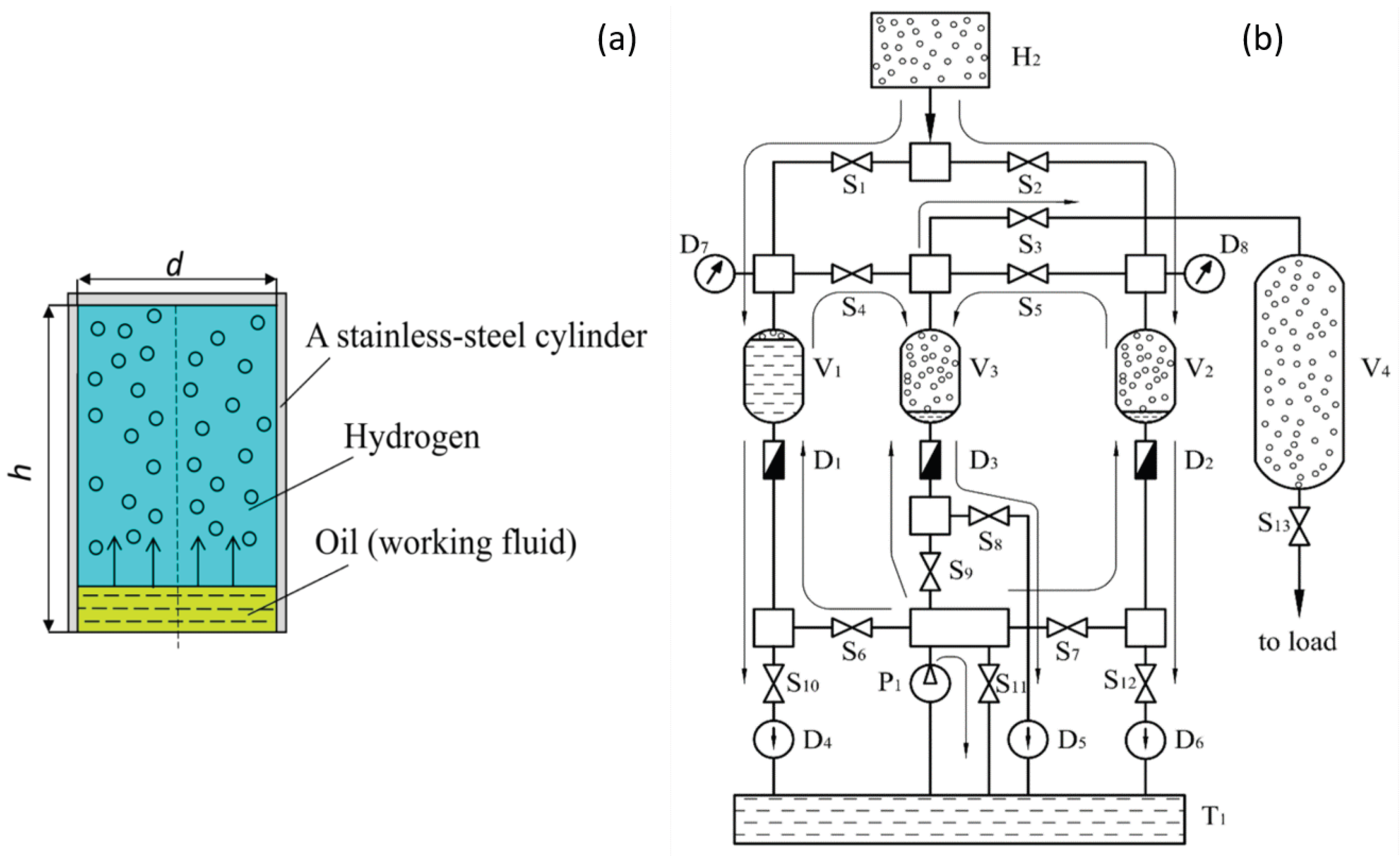
The liquid phase acts as the moving compression boundary, replacing the rigid gas-side piston characteristic of conventional reciprocating compressors. Hydrogen is compressed by displacement of the gas–liquid interface, which can reduce the need for piston rings, packing systems and other sliding gas-side seals. However, liquid-piston compressors are not mechanically simple systems: they still require hydraulic pumps, valves, reservoirs, sensors and control equipment, and their reliability depends on the coordinated operation of these components under cyclic pressure conditions [87,100,130].
Liquid-piston compressors should be distinguished from hydraulically driven solid-piston compressors. In the latter, the hydraulic fluid provides the actuation force while hydrogen is compressed by a solid piston. In a liquid-piston compressor, the working liquid itself forms the moving boundary of the gas volume and may be in direct or near-direct contact with hydrogen. This distinction leads to different heat-transfer mechanisms, contamination and gas-dissolution risks, interface dynamics and scale-up considerations. Liquid-piston compressors are therefore treated separately in this review as a distinct liquid-based compression concept.
Single-stage liquid-piston compressors represent the simplest configuration and typically comprise one compression chamber, a working-liquid supply system, inlet and outlet gas valves and a hydraulic circuit controlling liquid motion. Such systems are well suited to numerical and experimental investigation of heat transfer, gas-temperature evolution, pressure ratio, compression duration and working-fluid effects [81,82,131,176]. Their main limitation is the high pressure ratio that may need to be achieved within a single chamber, which can increase gas temperature, hydraulic power demand and mechanical requirements for valves and the compression chamber [57,82,87,88,177].
Multistage liquid-piston compression can distribute the total pressure increase among two or more chambers or stages [88,100]. Intermediate cooling or buffer volumes may be used between stages, allowing each chamber to operate over a lower pressure ratio [120,173]. Although conceptually similar to multistage mechanical compression with intercooling, liquid-piston systems require additional coordination of chamber operation, hydraulic flow distribution, valve timing and working-liquid management [88,174]. Such arrangements are particularly relevant for hydrogen refueling and high-pressure storage, where the final pressure may substantially exceed the electrolyzer or upstream buffer pressure [46,47,48,51,175].
The hydraulic drive is a central component of most liquid-piston compressor architectures. A hydraulic pump supplies the working liquid to the compression chamber, while pump flow rate, valve positions and hydraulic-circuit configuration determine the liquid-piston motion and compression rate [87,100,175,178,179]. This provides a degree of control over the compression trajectory but also contributes to total energy consumption and adds auxiliary components whose efficiency and reliability must be included in system-level assessment [180,181]. Reported performance should therefore clearly state whether energy consumption refers only to the compression process or also includes hydraulic pumping and other auxiliary losses [87,100,131,182,183,184,185,186,187].
Buffer volumes can be incorporated upstream, downstream or within multichamber liquid-piston systems. Upstream buffering stabilizes suction conditions and partially decouples variable electrolyzer output from the compression cycle, whereas downstream high-pressure storage can reduce continuous compressor operation and support intermittent demand peaks [46,47,48,105,188]. Internal or double-buffer configurations may additionally reduce pressure pulsations and improve pressure management between successive compression cycles [88,189]. These arrangements can be advantageous in decentralized systems subject to variable flow and repeated start–stop operation [91,190].
The working liquid is both the displacement medium and an important determinant of compressor performance [81,87,191]. Its thermophysical properties, hydrogen compatibility and potential for gas contamination influence thermal performance, hydraulic losses and system durability. These effects are discussed in detail in Section 4.2 and Section 4.3.
Ionic-liquid compressors represent a related but more specialized liquid-based compression concept. Ionic liquids can act as moving compression media while offering very low vapor pressure [53,98,192,193,194,195,196]. In some configurations, they replace a conventional solid piston or reduce direct mechanical contact between lubricated components and the compressed hydrogen, potentially limiting lubricant contamination and improving sealing behavior [191,197,198,199]. Their performance nevertheless depends on liquid properties, gas–liquid interaction, wave formation, viscosity, material compatibility, cost and long-term stability under repeated high-pressure operation [53,200,201,202,203,204,205,206,207]. In this review, ionic-liquid compressors are therefore considered within the broader family of liquid-based compression technologies but are distinguished from generic liquid-piston systems when the ionic liquid itself is the specialized working medium.
4.2. Thermal Management and Near-Isothermal Behavior
Thermal management is one of the defining features of liquid-piston hydrogen compression. During compression, part of the mechanical or hydraulic work increases the internal energy of the gas, causing its temperature to rise [81,82,87]. In conventional reciprocating compressors, heat is rejected primarily through the cylinder walls and external cooling systems, including intercoolers and aftercoolers. In liquid-piston systems, heat can additionally be transferred directly from the hydrogen to the working liquid through the gas–liquid interface. This additional heat-transfer pathway is the main reason why liquid-piston compressors are considered promising for near-isothermal operation [130,208,209,210,211,212].
Heat transfer in a liquid-piston compressor involves several coupled mechanisms. Hydrogen exchanges heat with the working liquid at the gas–liquid interface and with the chamber walls, while the liquid itself exchanges heat with the chamber wall and can transport absorbed heat through circulation or replacement between compression cycles. The relative importance of these mechanisms depends on chamber geometry, working-fluid properties, compression duration, pressure ratio and internal flow conditions. Thermal performance therefore cannot be assessed from final pressure alone but should be evaluated together with transient gas-temperature evolution and heat-transfer conditions [57,82,213].
The working liquid acts both as a displacement medium and as a thermal buffer. High heat capacity increases its ability to absorb compression heat, while higher thermal conductivity can improve heat spreading within the liquid and between the gas–liquid interface and the chamber wall. These thermal benefits, however, must be balanced against hydraulic and gas-quality constraints, because fluid properties that favor heat transfer may also influence pumping losses, hydrogen dissolution and liquid or vapor carry-over [53,81,87,131,214,215,216,217,218,219,220,221,222,223]. The broader implications of working-fluid selection are discussed in Section 4.3.
Compression duration is one of the key parameters governing the degree of near-isothermal behavior. At high liquid-piston velocities, less time is available for heat transfer and the compression process moves toward the adiabatic limit, resulting in a larger gas-temperature rise and greater departure from ideal isothermal compression [81,169,210]. A slower compression stroke allows more heat to be transferred from hydrogen to the working liquid and chamber walls, bringing the process closer to the isothermal limit [57,82]. However, slower compression reduces throughput and may require larger chambers or multiple parallel units for a given hydrogen demand. Liquid-piston compressor design therefore involves a fundamental trade-off between thermal performance and volumetric productivity [87,100,224,225].
The gas–liquid and gas–wall heat-transfer areas strongly influence thermal behavior. A larger heat-transfer area relative to the compressed gas volume generally enhances heat removal and reduces temperature gradients. In liquid-piston systems, this area is governed by chamber geometry, gas–liquid interface characteristics and internal heat-transfer structures. Chamber dimensions and aspect ratio therefore affect the thermal response by changing the available gas–wall and gas–liquid heat-transfer area and the characteristic heat-transfer distances [57,82,87,226,227,228,229,230,231,232,233]. These effects become particularly important during scale-up, when geometric changes may reduce passive heat-transfer effectiveness; chamber-scaling considerations are discussed further in Section 4.3.
Several strategies have been investigated to intensify heat transfer in liquid-piston compressors. Porous inserts, metallic foams and other high-conductivity structures can increase the effective heat-transfer area and reduce thermal gradients [170,216]. Fins, structured walls and internal heat exchangers can improve heat exchange between the gas, working liquid and chamber wall, while spray- or droplet-assisted concepts can increase gas–liquid contact area. Multichamber or staged configurations can additionally reduce the pressure ratio per chamber and provide opportunities for intermediate heat rejection [234,235,236,237,238,239,240]. These approaches may improve near-isothermal performance but can also introduce pressure losses, flow maldistribution, contamination risks, additional complexity and maintenance requirements. Heat-transfer enhancement should therefore be assessed at system level rather than solely by the resulting reduction in gas temperature.
Near-isothermal behavior must be defined using quantitative thermal and energetic criteria [87,123,241]. The presence of a liquid piston alone is not sufficient to classify a compressor as near-isothermal. Relevant indicators include the maximum gas-temperature rise during compression, average gas temperature relative to the initial state, effective polytropic exponent, deviation of actual compression work from the ideal isothermal work, isothermal efficiency and spatial temperature uniformity [81,212,216,242].
A useful practical benchmark is the comparison of the actual compression trajectory with the theoretical isothermal and adiabatic limits [216,243]. If the pressure–volume trajectory remains close to the isothermal path and the gas-temperature rise remains small at the required pressure ratio and flow rate, the compressor can be considered near-isothermal under those specific operating conditions [87,230]. Such classification should always be reported together with compression duration, chamber size, pressure ratio and cooling or heat-rejection strategy [244,245,246]. A system may exhibit near-isothermal behavior at low throughput or moderate pressure ratio but deviate substantially from it at higher compression rates or outlet pressures. Near-isothermal performance should therefore be regarded as an operating envelope rather than a fixed property of the compressor [247,248,249].
For decentralized green hydrogen infrastructure, improved thermal management can have important system-level consequences [81,82,100,158]. Limiting the gas-temperature rise can reduce the need for downstream or interstage cooling, decrease thermal loading of valves and chamber components and reduce the compression work required for a given pressure ratio [80,84,153]. However, achieving these benefits may require slower compression, controlled working-liquid motion or additional heat-transfer structures, which can affect throughput, auxiliary energy consumption, compactness and dynamic response [87,100,175]. Thermal performance must therefore be assessed together with variable inlet conditions, partial-load operation, start–stop cycling and hydrogen-purity requirements [91,97,105,129,250,251].
Overall, near-isothermal liquid-piston compression is best understood as a design objective rather than an inherent property of the technology. The degree of approach to isothermal compression depends on the balance between compression rate and heat-transfer rate, together with chamber geometry, working-fluid properties, heat-transfer area, enhancement strategy and operational control. These coupled factors provide the basis for the discussion of working-fluid selection, chamber scaling and control in Section 4.3.
4.3. Working-Fluid Selection, Chamber Scaling and Operational Control
The practical performance of a liquid-piston hydrogen compressor depends on the coupled effects of working-fluid properties, chamber geometry and scaling, compression trajectory, valve operation and heat transfer within the compression chamber. These factors influence gas-temperature rise and compression efficiency as well as hydrogen purity, hydraulic losses, dynamic response, reliability and scalability. Working-fluid selection, chamber design and operational control should therefore be considered as interconnected design tasks rather than optimized independently. The principal design, operating and modeling factors governing liquid-piston compressor performance and their system-level implications are summarized in Figure 7.
The working fluid is one of the key design parameters in liquid-piston compression because it functions simultaneously as the displacement medium, a thermal buffer and a potential source of interaction with the compressed hydrogen [81,130,243]. Relevant properties include density, specific heat capacity, thermal conductivity, viscosity, vapor pressure, chemical stability, hydrogen solubility and compatibility with chamber materials, seals and valves [131,252]. High heat capacity and thermal conductivity favor heat absorption and redistribution, whereas high viscosity can increase hydraulic pumping losses and reduce system efficiency [87,130,211,219]. Working-fluid selection therefore requires a balance between thermal performance, hydraulic efficiency and material compatibility.
Volatility and hydrogen solubility are particularly important because the working liquid is in direct or near-direct contact with the gas. Vapor formation, droplets, foaming or aerosol generation may lead to working-fluid carry-over into the hydrogen stream, which is a concern for PEM fuel-cell applications with strict purity requirements [38,53,61,62,63,64,65,66,67,68,87,129,130,131]. Dissolution of hydrogen in the liquid can reduce recoverable gas, influence the effective compression process and cause delayed gas release during depressurization or subsequent cycles [131,253,254]. The magnitude of these effects depends on fluid type, pressure, temperature, contact time and interfacial area [53,131]. A suitable working fluid should therefore combine favorable thermal properties with low volatility, limited hydrogen solubility, low contamination risk and long-term chemical stability under cyclic pressure operation.
Chamber geometry directly affects heat transfer, gas-volume reduction and liquid-piston motion. Chamber height, radius, aspect ratio and total volume determine the stroke length, wall area available for heat exchange and surface-area-to-volume ratio [130,243,244]. Increasing chamber size generally reduces the surface-area-to-volume ratio and can weaken passive heat removal, meaning that favorable thermal behavior observed in small laboratory chambers cannot necessarily be extrapolated directly to practical systems [57,82,87].
The chamber radius-to-height relationship also influences temperature distribution and interface stability. Tall, narrow chambers provide long strokes and compact radial dimensions but may develop stronger axial temperature gradients and longer heat-transfer distances. Wider chambers alter the distribution of heat-transfer area and characteristic heat-transfer distances, but their benefit depends on aspect ratio and stable gas–liquid interface motion [233,243,255]. Chamber geometry should therefore be optimized jointly for heat transfer, pressure generation and stable liquid-piston operation.
Beyond overall chamber dimensions, specific cylinder and hydraulic-circuit designs can also be used to control working-fluid behavior during hydrogen compression. A patented compression-cylinder concept has been proposed specifically to limit foam formation in the working liquid [256], while related patented hydraulic-compression architectures employ multiple compression cylinders, controlled working-fluid routing, buffer storage, valves and flow-monitoring elements [257]. These developments highlight that compression-chamber design is not solely a geometric or structural issue but also a fluid-management problem, because foaming, liquid entrainment, gas–liquid interface stability and repeatable filling and discharge can affect hydrogen purity, pressure control and cyclic operation. Such configuration-specific solutions should therefore be assessed together with hydraulic efficiency and validated under representative hydrogen pressures and repeated operating cycles [169,220,221,223].
Scale-up is not a purely geometric process. Larger systems may require higher working-liquid flow rates, more powerful hydraulic pumps, stronger chamber walls, larger valves and more advanced control hardware [173,181]. At the same time, chamber volume, wall heat-transfer area and working-liquid thermal capacity do not necessarily scale proportionally. Simple geometric enlargement may therefore reduce effective heat-transfer intensity and weaken the near-isothermal benefit observed at laboratory scale. Maintaining favorable thermal performance at larger scales requires coordinated optimization of chamber aspect ratio, liquid-piston trajectory, hydraulic efficiency and, where necessary, internal heat-transfer enhancement [258]. Scale-up should consequently be evaluated together with mechanical strength, hydraulic power demand, heat-transfer performance and system-integration requirements.
The liquid-piston trajectory is another important operational variable. Liquid motion depends on pump flow rate, valve actuation, chamber geometry, pressure difference and hydraulic-system dynamics. Faster piston motion increases throughput but reduces the time available for heat transfer, whereas slower motion favors heat rejection but lowers volumetric productivity [81,87,100,157,178,207,210]. The liquid-piston trajectory should therefore be treated as an actively controlled operating variable rather than merely as a consequence of pump operation.
Valve operation is equally important for reliable compression. Suction and discharge valves control gas intake and delivery and influence pressure losses, hydrogen backflow, volumetric efficiency and gas–liquid interface stability. Leakage, rebound, delayed closing or inappropriate valve characteristics can reduce effective throughput and generate pressure fluctuations within the chamber [140,196,202,259,260]. In multistage or buffer-assisted configurations, pressure equalization between chambers and storage volumes becomes particularly important. Buffer- and double-buffer configurations can help stabilize suction and discharge conditions, reduce pressure pulsations and improve operation under variable inlet pressure and intermittent hydrogen demand [88].
Operational control becomes particularly important when liquid-piston compressors are coupled to renewable-powered electrolyzers. Hydrogen production rate, compressor inlet pressure and available buffer inventory can all vary with time. Operational flexibility can be achieved by coordinating hydraulic-pump operation, liquid-piston trajectory and stroke duration, valve switching, and upstream and downstream buffer storage [103,105,180,261]. This requires reliable monitoring of chamber pressure, liquid level, gas temperature, hydraulic flow and valve actuation. Protection functions should also limit liquid carry-over, excessive interface oscillations and transient pressure excursions through appropriate valve sequencing, operating limits, interlocks and pressure-relief devices [169,220,221,222,262].
Numerical modeling, including computational fluid dynamics (CFD), conjugate heat-transfer and multiphysics approaches, is valuable for analyzing the coupled thermal and fluid-dynamic phenomena occurring during liquid-piston hydrogen compression [82,87,168]. Such models can resolve transient temperature distributions in the hydrogen, working liquid and chamber walls and estimate gas–liquid and gas–wall heat transfer [171,233,263]. They also enable systematic comparison of chamber dimensions, port arrangements, internal heat-transfer structures, piston trajectories and compression durations [57,157,206,244]. Parametric simulations can therefore assess the effects of initial pressure, liquid-piston velocity, wall material and thickness, and external cooling conditions on gas-temperature rise and compression work [233,244,255]. This is particularly useful because local gas-temperature measurements inside high-pressure hydrogen chambers are experimentally difficult and outlet temperature alone may not capture the maximum transient temperature.
Numerical predictions nevertheless require careful validation. The gas–liquid interface may deform, oscillate or become unstable, especially at high liquid velocities or unfavorable chamber and port geometries. Accurate representation of these effects requires appropriate multiphase modeling, sufficient spatial and temporal resolution, mesh-independence assessment and validation against transient experimental data. Many models also simplify valve and hydraulic-drive dynamics or neglect liquid carry-over, hydrogen dissolution, working-fluid contamination and real-gas behavior at high pressure [82,191,192,193,264,265,266,267,268,269,270]. Numerical results should therefore support, rather than replace, experimental validation when assessing performance or scale-up.
Overall, practical liquid-piston compressor performance results from the coupled effects of working-fluid properties, chamber geometry and scale, liquid-piston trajectory, valve operation and control strategy. Achieving near-isothermal operation requires these factors to be optimized together with hydraulic efficiency, hydrogen purity, reliability and scalability. Liquid-piston compressors therefore offer significant design flexibility but remain technically demanding systems for decentralized hydrogen infrastructure.
4.4. Advantages, Limitations and Technology Readiness
Liquid-piston hydrogen compressors offer several potential advantages over conventional solid-piston compressors and provide an alternative architecture to diaphragm compressors [37,98,99,130]. Their main mechanical advantage is the replacement of the rigid gas-side piston by a moving liquid interface, which can reduce the need for piston rings, packing systems and sliding gas-side seals and thereby eliminate some sources of friction, leakage and wear [50,98,99,130,271]. The working liquid can also absorb and redistribute part of the compression heat, potentially limiting hydrogen temperature rise and bringing the compression process closer to the isothermal limit under appropriate operating conditions [81,82,130,168]. These features make liquid-piston systems particularly attractive where thermal management, reduced gas-side wear and flexible operation are important.
These advantages do not eliminate system-level mechanical and operational complexity. Liquid-piston compressors still require hydraulic pumps, gas-side valves, reservoirs, seals, sensors and control systems, and their performance depends on the coordinated operation of the hydraulic and gas circuits. Pump efficiency, valve leakage and timing, pressure pulsations and control accuracy can affect compression efficiency, hydrogen purity and long-term reliability [173,207,259,260,272,273,274,275].
The gas–liquid interface is a specific source of uncertainty. At high liquid-piston velocities, large chamber dimensions or during transient operation, the interface may deform or oscillate, leading to non-uniform compression, pressure fluctuations, local temperature gradients and increased liquid entrainment [53,87,100,131]. Liquid carry-over through droplets, foam or aerosols may contaminate the compressed hydrogen and is particularly important for PEM fuel-cell applications with strict purity requirements [38,61,62,63,64,65,66,67,68,129]. Practical systems may therefore require separators, demisters, filters or other gas-cleaning components, adding pressure losses, maintenance requirements and system complexity [169,266,274].
Working-fluid properties remain central to both performance and reliability. Suitable fluids should combine favorable thermal properties with low volatility, limited hydrogen solubility, chemical stability and compatibility with seals, valves and chamber materials, while avoiding excessive hydraulic losses [191,192,193,194,223]. Ionic liquids are attractive in some configurations because of their very low vapor pressure, but viscosity, cost, materials compatibility and long-term stability remain important considerations [274]. These trade-offs reinforce the need to evaluate the working fluid as part of the complete compressor system rather than as an isolated thermal component.
Scale-up remains another major challenge. Thermal advantages observed in small chambers may diminish as the surface-area-to-volume ratio decreases and the requirements for liquid flow, hydraulic power, chamber strength and valve capacity increase [57,82,87]. Larger systems may therefore require coordinated optimization of chamber geometry, interface stability, hydraulic power and heat-transfer enhancement rather than simple geometric enlargement.
Experimental validation remains comparatively limited. Much of the published liquid-piston literature is based on numerical studies, analytical models or laboratory-scale test rigs [57,82,87,100,167,168,181,203,272]. These studies provide valuable information on thermal behavior, chamber geometry and working-fluid effects, but practical deployment requires validation under representative hydrogen pressures, flow rates, purity requirements and repeated operating cycles [181,202,207,223,263,264,272,275]. Outlet pressure and bulk temperature measurements alone are insufficient to characterize transient interface behavior, spatial gas-temperature gradients, hydrogen dissolution, liquid carry-over and valve dynamics; additional diagnostics such as fast-response temperature measurements, high-speed visualization, mass-balance measurements and valve-motion monitoring may therefore be required [169,202,220,221,259,272,273,274,275].
Long-term cyclic testing is particularly important for assessing technology readiness. Repeated start–stop operation, variable-load compression and pressure cycling can affect working-fluid stability, seals, valves, hydraulic pumps and chamber integrity [103,105,191,223,259,272,273,276]. A short-term demonstration of pressure increase is therefore insufficient to establish practical readiness. Assessment should include representative or accelerated cycling, monitoring of energy consumption and hydrogen purity, evaluation of working-fluid stability and post-test inspection of critical components [223,272,275,277,278].
Compared with reciprocating and diaphragm compressors, liquid-piston hydrogen compressors remain less commercially mature, although specific liquid-based and ionic-liquid concepts have demonstrated practical relevance [97,191]. Their technology readiness depends strongly on configuration, working fluid, pressure and flow range, and degree of system integration. Near-term applications are therefore most likely to be those in which moderate flow rates, improved thermal management, flexible operation and reduced gas-side mechanical wear offer sufficient advantages to justify the additional hydraulic and fluid-management complexity. The main advantages, limitations and technology-readiness considerations are summarized in Table 3.
Overall, liquid-piston compressors represent a developing hydrogen compression pathway with potential advantages in thermal management, reduced gas-side mechanical wear and controlled operation. Their practical performance, however, depends on stable gas–liquid interface behavior, suitable working-fluid properties, control of liquid carry-over and hydrogen dissolution, hydraulic-system efficiency, successful scale-up and long-term cyclic durability. These factors make liquid-piston compressors more appropriately viewed as application-specific complements to conventional mechanical compression rather than universal replacements. Their strongest potential lies in decentralized and dynamically operated hydrogen systems where moderate flow rates, thermal management and flexible control are more important than very high continuous throughput and fully established commercial maturity.
5. Electrochemical Hydrogen Compressors
Electrochemical hydrogen compressors (EHCs) represent a non-mechanical approach to hydrogen compression in which pressure increase is achieved through electrochemical reactions and selective proton transport rather than mechanical volume reduction [44,58]. Unlike reciprocating, diaphragm and liquid-piston compressors, EHCs do not require a moving mechanical compression boundary on the gas side [89,99]. Hydrogen is oxidized at the anode, transported through a proton-conducting membrane in ionic form and recombined as molecular hydrogen at the cathode, where it is delivered at elevated pressure. This operating principle makes EHCs particularly attractive for applications requiring high hydrogen purity, compactness, low vibration and integration with hydrogen-production or fuel-cell systems [132,279,280,281].
For decentralized green hydrogen infrastructure, EHCs offer two particularly relevant functions. They can potentially combine hydrogen purification and compression within a single device, which is advantageous when locally produced hydrogen must meet stringent downstream purity requirements. In addition, hydrogen transport is controlled electrically through the applied current, providing a potential means of adjusting compressor throughput to variable hydrogen production. These advantages, however, are accompanied by challenges related to membrane durability, hydrogen crossover, water and thermal management, impurity tolerance, high-pressure stack design, achievable throughput, lifetime and cost. Electrochemical compression should therefore be regarded as a complementary technology whose suitability depends strongly on the required pressure, flow rate, purity and operating profile [44,58,89].
5.1. Operating Principle and Main Components
The operating principle of an electrochemical hydrogen compressor is based on electrochemical hydrogen pumping through a proton-conducting membrane. Although its membrane–electrode architecture is similar to that used in proton-exchange membrane electrochemical devices, an EHC operates by selectively transporting hydrogen from a low-pressure anode compartment to a high-pressure cathode compartment. The basic operating principle is illustrated in Figure 8.
At the anode, molecular hydrogen is oxidized:
The generated protons migrate through the proton-conducting membrane under the applied electrochemical potential, while the electrons are transported through the external electrical circuit. At the cathode, protons and electrons recombine to form molecular hydrogen:
When low-pressure hydrogen is supplied to the anode and the cathode is connected to a high-pressure volume, hydrogen is electrochemically transported against the pressure gradient from the low-pressure side to the high-pressure side. The applied electrical potential provides the driving force for proton transport, while the membrane, seals and stack structure must limit hydrogen back-diffusion and external leakage in order to maintain the pressure differential [85,89].
The reversible voltage required for electrochemical hydrogen compression depends on the operating temperature and the pressure ratio between the cathode and anode compartments [85]. In practice, the applied cell voltage exceeds the reversible value because of electrode activation overpotentials, ohmic losses in the membrane, electrodes and electrical contacts, and mass-transport limitations [85,99]. EHC performance should therefore be evaluated not only by outlet pressure but also by cell voltage, current density, Faradaic efficiency, hydrogen crossover, specific energy consumption and stack durability [58,64,99].
The proton-conducting membrane is the central component of an electrochemical hydrogen compressor. In low-temperature EHCs, proton-exchange membranes are commonly used because they combine proton conductivity with separation of the anode and cathode gas compartments [280]. An appropriate membrane should provide high proton conductivity, low hydrogen permeability, chemical stability and sufficient mechanical strength under differential pressure [282,283]. Membrane thickness introduces an important trade-off: thinner membranes reduce proton-transport resistance but generally increase hydrogen crossover and mechanical sensitivity to differential pressure, whereas thicker membranes can suppress crossover and improve mechanical robustness at the expense of higher ohmic losses. This trade-off becomes increasingly important as the pressure differential and target outlet pressure increase. Hydrogen crossover and its implications for energy consumption have also been investigated in related PEM electrochemical devices [284,285].
Catalyst layers on both sides of the membrane promote hydrogen oxidation at the anode and hydrogen evolution at the cathode [58]. Platinum-based catalysts are commonly used because of their high activity and low overpotential for these reactions. Their cost and susceptibility to poisoning by impurities such as CO and sulfur-containing species, however, remain important limitations [58,62,63]. Catalyst loading, ionomer distribution, porosity and electrode microstructure affect the electrochemically active surface area, charge and mass transport, water distribution and overall cell performance [286,287]. These issues become particularly important when the EHC is used for simultaneous hydrogen purification and compression, where feed-gas impurities may directly affect catalyst activity [62,63,281].
Gas-diffusion layers (GDLs) provide gas distribution, electron conduction and mechanical support between the catalyst layers and bipolar plates [58,288]. Their pore structure, wettability, thickness and compression state influence gas transport, water distribution, electrical contact resistance and mechanical support of the membrane–electrode assembly [289,290]. In high-pressure EHCs, the GDLs must maintain continuous gas-transport pathways while withstanding assembly compression and pressure-induced mechanical loading.
Bipolar plates and flow fields distribute hydrogen over the active area, conduct electrical current and provide structural support to the membrane–electrode assembly [58,99,280]. Their geometry influences pressure drop, flow uniformity, water distribution, electrical contact and local mechanical stresses [291,292]. Bipolar-plate materials must combine corrosion resistance, electrical conductivity, low gas permeability and adequate mechanical strength [58]. At stack level, end plates, clamping elements, gaskets and seals must maintain sufficiently uniform compression while withstanding the internal pressure load and preventing hydrogen leakage [283,293]. Mechanical design is therefore closely coupled to electrochemical performance, particularly at high differential pressure [288].
Electrochemical hydrogen compressors can be arranged as single-stage or multistage systems. In a single-stage configuration, the required pressure increase is achieved within one electrochemical compression stage. This architecture is simpler but subjects the membrane, seals and supporting components to the full pressure differential. In multistage systems, hydrogen passes sequentially through several electrochemical stages operating at lower individual pressure ratios. This can reduce the pressure differential imposed on each stage, but increases the number of stacks, control complexity, balance-of-plant requirements and capital cost. The appropriate architecture therefore depends on target pressure, hydrogen throughput, energy consumption, durability and application requirements [44,58,89,99,132].
Different cell and stack geometries have also been investigated, including conventional plate-and-frame and tubular configurations. Tubular EHCs may offer advantages in pressure containment, sealing or modularity but introduce additional challenges related to current distribution, membrane fabrication, thermal management and scale-up. Overall, although the electrochemical compression mechanism is conceptually simple, practical EHC development requires simultaneous optimization of membrane transport, catalyst and electrode structure, pressure-resistant stack design and balance-of-plant integration.
5.2. Performance, Purification and Water Management
The performance of an electrochemical hydrogen compressor is commonly characterized by outlet pressure and pressure ratio, hydrogen flow rate, current density, cell voltage, Faradaic efficiency, specific energy consumption and performance stability [58,64,282]. According to Faraday’s law, the theoretical hydrogen transport rate is proportional to the applied current; increasing current density therefore increases the hydrogen pumping rate per unit active area [85,294,295]. However, higher current density generally increases activation, ohmic and mass-transport losses, thereby increasing cell voltage, electrical power consumption and heat generation. It can also intensify membrane-hydration and water-management requirements [294,296]. Higher current density can therefore increase throughput and reduce the active area required for a given hydrogen flow rate, but may reduce energy efficiency if thermal management, water management and membrane–electrode assembly design are not adequately controlled [58,89,297].
The achievable outlet pressure depends on membrane hydrogen permeability and mechanical integrity, support from porous layers and flow-field structures, sealing quality, stack compression and cathode-side pressure control [89,282,283,284]. Increasing the outlet pressure increases the differential pressure across the membrane, gas-diffusion layers and seals and may intensify hydrogen back-diffusion and mechanical loading of the membrane–electrode assembly and stack [288,292,298]. Reported EHC performance should therefore include anode and cathode pressures, pressure ratio, cell temperature, current density, membrane-humidification conditions and active area [283,299]. Without these parameters, meaningful comparison of hydrogen flux, cell voltage, outlet pressure and energy efficiency between studies is difficult [64,89,280,282].
Specific energy consumption is particularly important when EHCs are compared with mechanical and liquid-piston compressors. The principal energy input is electrical and depends on cell voltage and hydrogen throughput, but system-level consumption may also include power electronics, humidification, cooling, gas recirculation, pressure regulation and control. Consequently, EHC energy performance should be evaluated using clearly defined system boundaries and operating conditions rather than stack voltage alone [44,58,85,114,132]. The competitiveness of electrochemical compression depends on both pressure ratio and required throughput, as these parameters determine stack size, electrical demand and balance-of-plant requirements.
A distinctive advantage of EHCs is their potential to combine hydrogen separation, purification and compression in a single device [132]. Hydrogen is selectively oxidized at the anode, transported through the membrane as protons and recombined at the cathode, while many non-hydrogen species remain predominantly in the anode-side stream and can be removed through exhaust or purge [294,295,296,297]. This principle has been investigated for hydrogen mixtures containing nitrogen, methane, carbon dioxide and other diluents, although achievable purity and hydrogen recovery depend on membrane permeability, operating conditions and catalyst tolerance to feed-gas impurities [295,300,301]. Electrochemical compression can also upgrade hydrogen from carrier-based or reformate streams while simultaneously delivering it at elevated pressure [66,302]. EHCs can therefore function as both compressors and selective hydrogen separators, although crossover and catalyst poisoning may limit performance for some feed compositions [295,296,297,303].
Purification performance depends strongly on impurity type and concentration. Inert species can often be rejected because they do not participate in proton transport, whereas reactive contaminants may adsorb on catalysts, alter membrane behavior or participate in side reactions. Carbon monoxide, sulfur-containing compounds, ammonia, carbon dioxide, oxygen and moisture can affect electrochemical performance differently depending on concentration, operating temperature and electrode material [38,61,62,63,64,65,66,67,68]. EHC systems intended for purification may therefore require feed pretreatment, purge strategies or impurity-tolerant catalysts. These requirements are especially important when the compressed hydrogen is intended for PEM fuel-cell applications with stringent purity limits [127,128,129].
Water management is closely coupled to EHC efficiency and durability. Electro-osmotic drag transports water with protons from the anode toward the cathode, which can lead to non-uniform hydration of the membrane–electrode assembly. Excess water on the cathode side may obstruct gas-transport pathways and increase mass-transport resistance, whereas insufficient anode hydration reduces proton conductivity and increases ohmic losses [281,289,290,291]. These effects become more difficult to control at high current density and elevated cathode pressure. EHC operation therefore requires coordinated control of inlet humidity, cell temperature, hydrogen flow rate and purge conditions to maintain adequate membrane hydration without excessive water accumulation [282,283,289,295,297].
Hydrogen crossover is another important performance parameter. Molecular hydrogen can permeate from the high-pressure cathode side back toward the low-pressure anode side, reducing net hydrogen transport and Faradaic efficiency [58,85,89,99]. Crossover generally becomes more significant with increasing pressure differential, membrane permeability and temperature and is also influenced by membrane thickness and defects. It should therefore be reported together with membrane type, pressure ratio, operating temperature and current density when comparing EHC performance.
Thermal management is also closely coupled to electrochemical performance. Although EHCs do not heat hydrogen through mechanical volume reduction in the same manner as reciprocating compressors, heat is generated by activation and ohmic losses and by auxiliary equipment [44,298]. Temperature influences proton conductivity, electrode kinetics, water transport, hydrogen permeability and component stability [280,281]. Moderate increases in temperature may improve conductivity and reaction kinetics, whereas excessive temperature can disrupt hydration and accelerate material degradation. EHC thermal management must therefore balance electrochemical performance, membrane hydration and component durability [304,305].
5.3. Durability, Cost and Dynamic Operation
Durability remains one of the main barriers to wider deployment of electrochemical hydrogen compressors [306]. The membrane is exposed to combined mechanical, chemical and electrochemical stresses arising from differential pressure, hydration–dehydration cycling, temperature variation and possible feed-gas contaminants [307,308]. During long-term operation, particularly under repeated start–stop and load-changing conditions, these stresses may promote membrane deformation and progressive loss of mechanical integrity. Evidence from EHCs and closely related pressure-differential PEM devices indicates that cyclic swelling and contraction, elevated pressure and local material defects can contribute to membrane thinning, pinhole formation and mechanical failure [297,304,309,310]. Such degradation increases hydrogen crossover, lowers Faradaic efficiency and may ultimately lead to internal leakage, loss of outlet pressure or hydrogen purity, and stack failure [311].
Catalyst and catalyst-layer degradation can also limit EHC lifetime [58,281]. Platinum-based catalysts may undergo particle growth, dissolution or redistribution and can be poisoned by feed-gas impurities [312,313]. Repeated humidity, pressure and current cycling may additionally alter catalyst-layer microstructure, ionomer pathways, porosity and mass-transport characteristics. Species such as CO and sulfur-containing compounds can inhibit the hydrogen oxidation reaction and increase the required cell voltage [62,314,315]. Regeneration strategies may restore part of the catalyst activity for some contaminants, but recovery depends on the impurity and exposure history. Feed-gas quality and catalyst impurity tolerance therefore remain important determinants of long-term performance.
Mechanical stability under differential pressure is particularly important in high-pressure EHCs [89,283]. The membrane–electrode assembly, gas-diffusion layers, gaskets, bipolar plates, end plates and clamping system must maintain structural integrity while separating the low- and high-pressure hydrogen compartments [288]. Non-uniform stack compression can create local stress concentrations, membrane deformation and leakage paths, while repeated pressure cycling can degrade seals and interfaces. High cathode pressure also increases both mechanical loading and the driving force for hydrogen permeation. Stack design must therefore combine electrochemical performance with sufficient mechanical integrity for sustained operation under high differential pressure [292,293].
Cost is another important limitation. EHC systems require proton-conducting membranes, noble-metal catalysts, corrosion-resistant bipolar plates, precision seals, pressure-resistant end plates, power electronics and water- and thermal-management equipment [89,280,281]. Costs can increase substantially when large active membrane areas, multiple cells or several compression stages are required to achieve higher hydrogen throughput and outlet pressure [316]. Important cost-reduction pathways therefore include lower catalyst loading, improved membrane lifetime, less expensive bipolar-plate materials, optimized stack sizing and simplified balance-of-plant systems [317,318].
The absence of moving mechanical compression parts does not automatically imply longer service life than that of mature mechanical compressors [44,58]. EHC degradation involves different mechanisms, including membrane deterioration and crossover, catalyst degradation or poisoning, seal leakage, water-management instability and mechanical fatigue of stack components. Technology readiness should therefore be evaluated through long-term or accelerated testing under representative pressure, current-density, humidity, impurity and load-cycling conditions rather than through short-term pressure demonstrations alone [297,306,312,315,319,320].
Dynamic operation is potentially attractive for decentralized green hydrogen systems because hydrogen transport can be modulated electrically through the applied current [44,85,89,294,321]. This enables the EHC throughput to be adjusted in response to changing hydrogen availability and downstream demand and can facilitate integration with renewable-powered electrolyzers [105,318,322]. However, dynamic operation also introduces additional durability and control challenges. Rapid current changes can disturb membrane hydration, produce temperature transients and modify the pressure distribution across the membrane, while repeated start–stop operation can intensify hydration–dehydration cycling and mechanical loading of the membrane–electrode assembly and seals [287,294,295,296,297,304,307]. High current-density peaks increase voltage losses, electrical power consumption and heat generation, whereas operation at very low current density reduces throughput. Dynamic EHC operation therefore requires coordinated control of current density, anode and cathode pressures, temperature, humidity, purge conditions and downstream storage state [295,299,317].
Integration with electrolyzers can follow different configurations. An EHC may operate downstream of drying and purification units and receive relatively clean hydrogen through an intermediate buffer tank [45,105]. Alternatively, it may combine purification and compression when the feed contains species that can be retained in the anode-side stream or removed through purging [64,65,66]. In either case, the EHC inlet pressure and flow rate depend on electrolyzer technology, operating load and balance-of-plant configuration [103,105,250]. Intermediate buffer storage can partially decouple hydrogen production from compression and stabilize EHC inlet conditions, although it adds equipment, footprint and capital cost [17,47,261,322].
Overall, EHCs combine high-purity hydrogen compression, purification potential, compact architecture and electrically controlled operation. Their principal limitations are membrane and stack durability, hydrogen crossover, water management, impurity sensitivity, material and system cost, and limited long-term field evidence. They are therefore best regarded as complementary rather than universal alternatives to mechanical and liquid-piston compression. Their strongest application potential lies where high hydrogen purity, moderate throughput, compactness and electrical controllability outweigh the need for very large continuous flow.
6. Complementary and Hybrid Compression Concepts
The preceding sections examined the principal hydrogen compression technologies considered most relevant to decentralized green hydrogen infrastructure: conventional mechanical compressors, liquid-piston systems with the potential for near-isothermal operation, and electrochemical hydrogen compressors. These technologies, however, do not cover the full range of available compression concepts. Thermally driven and hybrid systems may provide advantages in specific applications, particularly where low-grade or waste heat is available, hydrogen flow rates are moderate, high purity is required, or the overall pressure increase can be distributed among complementary stages. Metal-hydride compressors and hybrid compression architectures are therefore considered here as application-specific complements to the principal compression technologies rather than as universal replacements for conventional mechanical compression [56,69,70,102].
6.1. Metal-Hydride Compressors
Metal-hydride (MH) compressors are thermally driven hydrogen compression systems based on the reversible absorption and desorption of hydrogen by metal alloys or intermetallic compounds capable of forming hydrides. During the absorption stage, hydrogen is absorbed by the hydride-forming material at relatively low temperature and pressure. During desorption, heat is supplied to the hydride bed, shifting the thermodynamic equilibrium toward hydrogen release at a higher pressure. The achievable pressure ratio is therefore governed by the pressure–temperature equilibrium of the selected metal–hydrogen system, the operating temperature range and the effectiveness of thermal management [69,70]. The basic operating principle of metal-hydride compression is illustrated in Figure 9.
In a practical metal-hydride compressor, the hydride bed is cyclically cooled and heated. Cooling promotes hydrogen absorption at lower pressure, whereas heating shifts the equilibrium toward hydrogen desorption at higher pressure. Higher outlet pressures can be achieved using multistage arrangements with different hydride materials or multiple beds operating over different temperature ranges. Unlike mechanical compression, the pressure increase is generated by a thermally induced shift in the metal–hydrogen equilibrium rather than by direct reduction of the gas volume [69,70,83].
One of the principal advantages of metal-hydride compressors is their ability to use thermal energy as the driving input for hydrogen compression [69,70]. This makes them potentially attractive at sites where low-grade or waste heat is available from industrial processes, electrolyzer cooling circuits or other balance-of-plant equipment, as well as where solar thermal energy can be supplied [323,324,325]. In such applications, heat that would otherwise be rejected can provide part of the compression duty and reduce demand for high-grade electrical energy. The practical benefit, however, depends strongly on the temperature level, continuity and availability of the heat source, together with hydride selection, heat-exchanger design, heat-transfer rate and cycling strategy [74,83,325,326,327].
Metal-hydride compressors may also offer advantages in hydrogen purity and mechanical simplicity. Hydrogen is selectively absorbed by the hydride-forming material, which can provide a degree of separation or purification, although the effect depends on impurity type and concentration and on the selected hydride material; some reactive impurities can poison or deactivate the alloy [59,69,328]. In addition, metal-hydride compressors do not require a moving mechanical gas-compression boundary, which can reduce vibration, noise and some sources of mechanical wear [69,102,329]. These characteristics make them potentially attractive for small stationary systems, niche hydrogen-refueling applications and integrated hydrogen storage–compression concepts [71,90,330].
The principal limitations of metal-hydride compression are associated with heat and mass transfer and material behavior [59,69,70,72]. Hydrogen absorption and desorption can be relatively slow, particularly when heat transfer within the hydride bed is insufficient [59,83,331]. The low effective thermal conductivity of many hydride beds makes rapid and uniform heat addition or removal difficult [73,75,332]. Temperature gradients can therefore develop within the bed, reducing usable hydrogen capacity, increasing cycle time and limiting hydrogen throughput [72,83]. Heat exchangers, fins, metal foams, expanded graphite and other thermal-conductivity-enhancement strategies are commonly used to improve heat-transfer rates and temperature uniformity [73,75,333].
Material degradation is another important limitation [69,71,133]. Repeated hydrogen absorption and desorption can cause decrepitation and pulverization, structural or phase changes, increased hysteresis, loss of reversible hydrogen capacity and changes in equilibrium behavior [59,334]. Feed-gas impurities may poison or deactivate the hydride material, reducing absorption kinetics and usable capacity [335]. Repeated thermal and pressure cycling can also generate mechanical stresses in the hydride bed, containment vessel and internal heat-transfer structures as particles expand, fragment, redistribute or agglomerate [71,336]. Long-term stability under representative hydrogen pressures, temperatures, impurity levels and cycling conditions is therefore essential for assessing practical technology readiness [71,133,337].
From a system perspective, metal-hydride compressors are best suited to applications where heat integration, quiet operation and hydrogen purity are more important than high continuous throughput or rapid transient response [69,70,102]. Potential applications include small-scale hydrogen refueling stations, stationary or off-grid hydrogen systems and industrial sites with available low-grade or waste heat [90,325,329,338]. Their applicability to high-flow or rapidly varying duty cycles remains limited by sorption kinetics, hydride-bed heat transfer, heat-exchanger complexity, material degradation and thermal inertia [72,73,74,133,325].
6.2. Hybrid Compression Systems
Hybrid compression systems combine two or more compression technologies within a single pressure-boosting chain. Instead of relying on one compressor type to provide the entire pressure increase from production to storage or end use, the overall pressure ratio is distributed among complementary stages [102,114]. The objective is to operate each technology within the pressure, flow-rate and purity range where its specific advantages are most effectively utilized. Depending on the configuration, hybridization may reduce the duty imposed on the primary compressor, improve thermal management or hydrogen purity, and increase operational flexibility [56,74,339].
One possible architecture combines electrochemical and mechanical compression. An electrochemical hydrogen compressor can provide initial pressure boosting and, where required, selective purification, followed by a mechanical compressor for higher-pressure and higher-throughput duty [92,97,98]. This arrangement can limit the pressure differential imposed on the EHC while retaining the high-pressure capability and maturity of mechanical compression. Where purification is required, the electrochemical stage may also remove non-hydrogen components before downstream compression [44,64,65,89,132]. The overall benefit depends on feed-gas composition, required pressure ratio and throughput, EHC membrane and catalyst durability, water management, and the relative capital and operating costs of the electrochemical and mechanical stages [58,89,315,340].
Mechanical–liquid-piston hybrid systems represent another possible pathway, although hydrogen-specific evidence remains comparatively limited [97,102]. A liquid-piston stage may be used at low or intermediate pressure to limit gas-temperature rise before final pressure boosting by a conventional mechanical compressor [81,87,98,210]. Conversely, mechanical pre-compression may be followed by a liquid-piston stage where enhanced heat transfer is beneficial. Such arrangements could distribute the pressure ratio and thermal load more favorably across the compression train. Their practical advantage, however, must be weighed against additional hydraulic equipment, working-liquid management, valve coordination, control requirements and hydrogen-purity risks. Related two-stage pump–compressor and hydraulic-accumulator concepts also show that fluid compressibility, pressure-energy recovery and interstage coordination can materially affect hybrid-system performance [341,342].
Electrochemical–metal-hydride combinations provide a further hybrid option, particularly where both electrical flexibility and low-grade or waste heat are available [74,102,343]. The electrochemical stage can provide selective purification, electrically controlled compression and intermediate-pressure regulation, whereas the metal-hydride stage can provide thermally driven pressure boosting or integrated storage–compression functionality [69,70,71]. Such configurations allow compression duty to be distributed between electrically and thermally driven processes. Effective integration nevertheless requires careful matching of pressure levels, hydrogen flow rate, available heat-source temperature, EHC water management, hydride cycling strategy and feed-gas impurity tolerance.
A central design question in any hybrid compression system is the allocation of pressure ratio and operating duty between stages. The optimum distribution depends on inlet and outlet pressures, hydrogen flow profile, purity requirements, available thermal energy, cooling capacity, dynamic operating mode and technology cost. A liquid-piston stage may be advantageous where heat removal is a dominant constraint, an electrochemical stage where purification or electrical controllability is valuable, and a metal-hydride stage where suitable waste heat is available and slower cycling is acceptable. Pressure staging should therefore be optimized at system level rather than determined only from nominal compressor ratings [56,97,102,114].
Hybrid architectures may also help decouple the primary compressor from fluctuations in production and demand. Buffer storage and complementary compression stages can allow the main compressor to operate over a narrower pressure or flow range, potentially reducing thermal and mechanical cycling. In decentralized hydrogen systems, such load sharing is most useful when electrolyzer output, buffer-storage state, compressor operation and downstream demand are coordinated at system level [93,105,113].
The main disadvantage of hybrid compression is additional integration complexity [56,114,344]. Combining multiple technologies requires additional valves, sensors, controllers, heat exchangers, power electronics, safety systems and maintenance interfaces. Interstage conditions must be managed to avoid pressure oscillations, hydrogen losses, impurity accumulation, overheating, membrane dehydration, hydride degradation or working-liquid carry-over. Hybridization is therefore justified only when gains in efficiency, purity, thermal management or operational flexibility outweigh the additional capital cost and balance-of-plant complexity. Recent computational and experimental studies of multistage and larger-scale metal-hydride compressors further expand the evidence base for integrating thermally driven stages into hybrid compression systems [345,346,347,348].
Overall, hybrid compression broadens the design space for decentralized green hydrogen infrastructure by allowing different pressure ranges and functions to be assigned to technologies that match them best. Its practical value will depend on system-level optimization, long-term validation, realistic cost assessment and the identification of applications in which hybridization provides a measurable advantage over a single compression technology.
7. Comparative Assessment for Decentralized Green Hydrogen Infra-Structure
No single hydrogen compression technology is optimal across all decentralized green hydrogen applications. The suitability of each compressor class depends on its operating envelope, including pressure ratio, hydrogen flow-rate range, thermal performance, hydrogen purity, dynamic flexibility, maintenance requirements, scalability and technology readiness. Technology selection should therefore be based on the requirements of the complete production–conditioning–storage–demand chain rather than on maximum outlet pressure or nominal capacity alone.
Application priorities differ across system configurations. Small on-site electrolyzer systems may prioritize flexible operation, part-load performance and high hydrogen purity, whereas hydrogen refueling stations require high discharge pressure, sufficient peak throughput and compatibility with cascade storage. Larger industrial or network-connected applications may prioritize continuous high flow rates, while heat-integrated systems may benefit from thermally driven or hybrid compression concepts. The following assessment compares the main technologies considered in this review using the criteria defined in Section 2 and identifies the operating conditions and application contexts in which their respective advantages and limitations become most relevant.
7.1. Cross-Technology Comparison
Direct comparison of hydrogen compression technologies is challenging because published performance data are reported under different inlet and outlet pressures, flow rates, cooling strategies, system boundaries and levels of technological maturity. Specific energy consumption, for example, may refer only to the compression unit or may also include auxiliary loads such as cooling, hydraulic pumping, power electronics, humidification, valves, control systems and gas conditioning. Likewise, a reported maximum outlet pressure alone does not indicate practical suitability for storage or refueling unless hydrogen throughput, duty cycle, thermal performance, dynamic operation and reliability are also considered. Table 4 therefore provides a structured qualitative, application-oriented comparison of the principal technologies, focusing on their operating role, energy and thermal characteristics, hydrogen-purity and dynamic-performance implications, key limitations and supporting evidence base. The qualitative assessments synthesize the evidence discussed and cited in Section 3, Section 4, Section 5 and Section 6 and are intended to indicate relative application suitability rather than provide a numerical ranking of technologies.
Table 4 highlights distinct application envelopes rather than a universal ranking of hydrogen compression technologies. Conventional mechanical compressors remain the most mature options for high-pressure and higher-throughput applications, but their performance is accompanied by gas heating, sealing, wear and maintenance requirements. Liquid-piston and electrochemical compressors address different system constraints: liquid-piston systems offer potential advantages where thermal management and controlled compression are important, whereas EHCs are particularly attractive where hydrogen purity, compactness and electrical controllability are prioritized. Ionic-liquid compressors represent a specialized liquid-based pathway with low volatility but additional two-phase-flow and fluid-management challenges. Metal-hydride compressors are most relevant where suitable low-grade or waste heat is available and slower cycling is acceptable, while hybrid architectures can allocate pressure boosting, purification and thermal-management functions among complementary stages. Technology selection should therefore be based on the dominant requirements of the specific application rather than on maximum pressure or nominal capacity alone.
7.2. Technology Selection by Application
Technology selection for decentralized green hydrogen infrastructure should be application-driven. A compressor technology that is well suited to one system configuration may be inappropriate in another because the relevant requirements depend on hydrogen production rate, inlet and target pressures, purity requirements, dynamic operating profile, available heat sources and maintenance constraints. Compressor selection should therefore consider the complete system, including the electrolyzer, gas-conditioning equipment, buffer storage, high-pressure storage and end-use demand.
Table 5 summarizes suitable primary and complementary compression options for representative application scenarios based on the evaluation criteria defined in Section 2 and the cross-technology evidence synthesized in Section 3, Section 4, Section 5, Section 6 and Section 7.1. The table should not be interpreted as a universal ranking of technologies, but as an application-oriented guide reflecting the dominant technical requirements and limitations of each use case.
For on-site and small decentralized hydrogen systems, the compressor must accommodate variable hydrogen production while meeting downstream pressure and purity requirements [42,103,105,113,250,261,322]. Oil-free reciprocating and diaphragm compressors remain attractive because of their technical maturity and established high-pressure capability [37,92,97,98]. Electrochemical compressors become particularly relevant where high hydrogen purity, compactness or combined purification and compression are required [44,64,65,89,132,300,301,302,303]. Liquid-piston compressors may offer advantages where thermal management and controllable compression trajectories are important [81,87,130,178,180,222]. However, both electrochemical and liquid-piston systems still require long-term validation under representative pressures, variable-load conditions and repeated start–stop operation [181,272,297,304,319].
Hydrogen refueling stations impose particularly demanding requirements because high discharge pressure, sufficient hydrogen throughput and repeated operating cycles must be combined with reliable cascade-storage operation [8,37,92,97,98,112]. Reciprocating, diaphragm and hydraulically driven piston compressors therefore remain the most established options [37,92,97,98,139,140]. Their limitations include gas heating and cooling demand, leakage and valve wear, diaphragm fatigue, seal and piston-ring degradation, and maintenance under repeated pressure cycling [49,50,84,136,141,142,143,144,145,146,147,148,149,150,151,152,153,154,155,156,157,158,278]. Electrochemical, liquid-piston and ionic-liquid systems may serve as complementary stages where purification, thermal management or intermediate pressure boosting provides a system-level advantage, although their use depends on throughput, pressure requirements, maturity and cost [56,97,102,114,191].
In high-purity and fuel-cell applications, gas quality becomes a dominant selection criterion [38,63,127,128,129]. Diaphragm compressors are attractive because the hydrogen stream is physically separated from the lubricated hydraulic drive [37,98], while electrochemical compressors can combine selective hydrogen separation with compression [64,65,89,132,300,301,302,303]. Their applicability nevertheless depends on membrane durability, hydrogen crossover, water management and catalyst tolerance to feed-gas impurities [281,289,295,297,304,312,315,318]. Liquid-piston systems may also be considered where working-fluid carry-over, vapor or aerosol contamination and hydrogen dissolution can be adequately controlled, potentially requiring separators, demisters, filters or other downstream gas-cleaning measures [169,191,192,193,200,204,220,221,223,242,266].
Industrial sites with access to low-grade or waste heat provide a distinct application niche for metal-hydride compression. In such systems, thermal energy drives hydrogen absorption–desorption cycles and can reduce the demand for high-grade electrical compression energy [59,69,70,323,324,325]. Metal-hydride compressors are therefore most attractive where moderate flow rates, quiet operation, heat integration and high hydrogen purity are valued more highly than rapid transient response [69,70,90,102,325,329]. Their limitations remain slow sorption kinetics, low effective hydride-bed thermal conductivity, heat-exchanger requirements and material degradation under repeated cycling [72,73,83,133,331,332,333,334,335,336,337]. Hybrid systems may become advantageous where waste heat and electrical flexibility are both available and compression duty can be distributed between complementary stages [114,339,341,343,344,345,346,347,348].
For large continuous hydrogen flows, centrifugal compressors and large multistage reciprocating compressor trains remain more appropriate than electrochemical, metal-hydride or small liquid-piston systems [97,102,115,122]. Centrifugal compressors are particularly relevant to industrial hydrogen supply, pipeline transmission and large centralized production facilities [122,349]. However, hydrogen’s low molecular weight and density limit the pressure rise achievable per stage, often requiring high impeller tip speeds, multiple stages and intercooling [97,164,165]. Their stable operating range is also constrained by surge and choke, making them less suitable for small systems with strongly fluctuating flow [97,161,162,350].
Buffer storage is a cross-cutting element in decentralized hydrogen systems because it can partially decouple variable hydrogen production from compressor operation and downstream demand [47,94,105,166]. Upstream buffers stabilize compressor suction conditions, whereas downstream high-pressure and cascade storage reduce the need for the compressor to respond directly to short-duration demand peaks [46,47,94,105,108,112,160,166,261]. Compressor sizing and control should therefore be optimized together with buffer-storage capacity and pressure configuration rather than treated as independent equipment decisions [108,114,351,352].
Dynamic operation further differentiates the technologies. Mechanical compressors tolerate a broad range of established operating duties but repeated load and pressure cycling can accelerate wear of valves, seals and piston rings [49,50,143,144,145,146,278]. EHC throughput can be modulated through electrical current, although membrane hydration, temperature and differential pressure must remain within acceptable limits [294,295,296,297,298,299,304,318,319]. Liquid-piston compressors can adjust hydraulic flow, stroke duration and piston trajectory, but reliable dynamic operation requires stable gas–liquid interface motion, valve control and limitation of liquid carry-over [169,178,180,200,202,204,207,259,260,263,266,272]. Metal-hydride compressors are inherently slower because their transient response is governed by sorption kinetics, heat-transfer rates and hydride-bed thermal inertia [59,69,70,72,73,83,325,326,331,332].
Overall, compressor selection is governed by the dominant system constraint rather than by a single performance metric. Mechanical compression remains the reference choice where maturity, high pressure and high throughput dominate. Electrochemical compression is particularly attractive where hydrogen purity, compactness and electrical controllability are prioritized. Liquid-piston systems may provide advantages where thermal management and controlled compression are central, while metal-hydride compressors are most relevant where suitable waste heat is available and slower cycling is acceptable. Hybrid architectures become attractive when pressure boosting, purification, thermal management or storage functions can be distributed among complementary technologies.
8. Research Gaps and Future Perspectives
The preceding comparison shows that hydrogen compression in decentralized green hydrogen infrastructure should be considered at the system level rather than solely as a component-level engineering problem. Compressor performance is coupled to electrolyzer operation, gas conditioning, buffer and high-pressure storage, end-use demand, hydrogen-purity requirements and dynamic operating conditions. Although conventional mechanical compressors are commercially mature and liquid-piston, electrochemical, metal-hydride and hybrid systems offer complementary capabilities, several research gaps still limit reliable cross-technology comparison and application-specific technology selection.
A first major gap is the lack of widely adopted standardized test conditions and consistent performance metrics across hydrogen compression technologies [97,102,181,319]. Published data are obtained at different inlet and outlet pressures, hydrogen flow rates, temperatures, cooling conditions and system boundaries. Specific energy consumption may refer only to the compression unit or may include auxiliary loads such as cooling, hydraulic pumping, humidification, power electronics, purge flows and gas conditioning. Similarly, efficiency may be reported using different thermodynamic, electrochemical or system-level definitions. Future studies should therefore report the complete operating envelope, including inlet and outlet pressures, pressure ratio, hydrogen flow rate, temperature, duty cycle, cooling strategy, auxiliary energy demand, hydrogen purity and measurement uncertainty [26,97,117,118,121]. A harmonized reporting framework would improve the transparency and comparability of performance data across compressor technologies.
A second major gap is the limited availability of long-term experimental data for emerging compression systems [97,181,319]. Liquid-piston compressors require validation of gas–liquid interface stability, working-fluid carry-over and degradation, hydrogen dissolution, valve behavior and hydraulic-system reliability under representative hydrogen pressures, flow rates and repeated operating cycles [57,81,82,87,100,181,272]. Electrochemical compressors similarly require long-term evaluation of membrane durability, hydrogen crossover, catalyst stability, water management, seal integrity and stack mechanical stability under differential pressure [44,58,89,99,132,297]. Short-term demonstrations of pressure increase are therefore insufficient to establish practical readiness. Future studies should include long-duration or accelerated cycling, monitoring of hydrogen purity and energy consumption, and post-test analysis of critical components.
A third research gap concerns partial-load operation, transient behavior and repeated start–stop cycling. Renewable-powered electrolysis exposes compression systems to variable hydrogen production rates, changing suction pressures and intermittent flow [42,103,105,113,250,261,322]. These conditions affect compressor technologies differently. Mechanical compressors experience cyclic loading and wear of valves, seals, piston rings and diaphragms [49,50,143,144,145,146,152,156,278]. Liquid-piston systems must maintain stable gas–liquid interface motion and control pressure oscillations and working-fluid carry-over [169,200,202,204,259,260,263,272]. Electrochemical compressors must maintain membrane hydration, thermal balance and acceptable differential pressure during changes in current density and operating load [294,295,296,297,298,299,304,307,308,309,310,318,319]. Metal-hydride compressors are less responsive to rapid load variation because their transient behavior is governed by sorption kinetics, heat-transfer rates and hydride-bed thermal inertia [59,69,70,72,73,83,325,326,331,332]. Future work should therefore move beyond nominal steady-state operating points toward dynamic experiments, control-oriented models and experimentally validated transient simulations under representative renewable-hydrogen operating conditions [103,113,166,181,272,297,299,319,321].
A fourth research gap is the lack of reliable cost, maintenance and lifetime data, particularly for emerging and hybrid compression technologies [97,102,114,319,325,344]. Capital expenditure (CAPEX) and operating expenditure (OPEX) depend not only on the compressor itself but also on cooling systems, hydraulic circuits, humidification and water-management equipment, gas purification, control hardware, buffer storage, component replacement, inspection requirements and downtime [17,47,105,112,114,118,344]. Long-term field experience is more extensive for mature mechanical compressors, although component lifetime under highly variable green-hydrogen operation remains application-dependent [37,49,50,98,145,154,278]. For liquid-piston and electrochemical compressors, economic projections remain uncertain because degradation rates, maintenance intervals and component-replacement data are still limited [97,181,191,272,280,281,297,316,319]. Metal-hydride economics additionally depend strongly on hydride-material cost, heat-exchanger design and thermal-cycling stability [59,69,74,83,133,325,327,334,335,336,337]. Future techno-economic assessments should therefore incorporate realistic lifetime assumptions, part-load operation, auxiliary energy demand, component replacement, maintenance schedules and purity-management requirements rather than relying primarily on idealized efficiency or initial capital cost [74,114,118,181,297,319,325,339,344].
A fifth priority is deeper integration of compression with electrolyzers, buffer storage and complementary compression stages [56,102,114,339,344]. Hybrid architectures can distribute pressure boosting, purification and thermal-management functions among technologies operating under different conditions [74,114,339,340,341]. Mechanical compressors can provide mature high-pressure and high-throughput compression [97,98,340], electrochemical stages can provide selective purification and electrically controlled pressure boosting [64,65,89,294,300,301,302,303], liquid-piston stages can improve thermal management within selected pressure ranges [81,87,130,208,210], and metal-hydride systems can utilize low-grade or waste heat where rapid dynamic response is less critical [69,70,325,329,343]. The benefit of hybridization depends on pressure-ratio allocation, coordinated operation of individual stages, buffer-storage design, heat-source availability, impurity management and the additional balance-of-plant complexity introduced by the hybrid architecture [47,74,105,114,166,325,339,342,343,344]. Recent numerical and experimental studies also demonstrate progress toward multistage, high-pressure and larger-scale metal-hydride compression [345,346,347,348].
Buffer-storage design is particularly important for integrated decentralized systems because it determines how strongly compressor operation follows variations in electrolyzer output and downstream demand [47,94,105,166]. Appropriate upstream and downstream buffering can stabilize compressor operating conditions, reduce short-term pressure and flow fluctuations and modify compressor duty cycles. Compression technology, buffer capacity and storage-pressure configuration should therefore be optimized together rather than treated as independent design variables [108,114,351,352].
Adaptive control represents a related future research direction for systems coupled to variable electrolysis [103,105,113,250,261,322]. Compressor operation should be coordinated with electrolyzer load, gas-conditioning conditions, buffer-storage pressure, high-pressure storage state and end-use demand [45,94,105,108,261,322]. Model predictive control, digital twins, fault diagnostics and real-time optimization may support such integration, although their implementation requires reliable dynamic models, online sensor data and experimental validation [105,145,146,156,166,190,321,353,354]. Relevant control variables are technology-specific: EHC operation depends on current density, anode and cathode pressures, humidity, temperature and purge strategy [294,295,296,297,298,299,304,318,321], whereas liquid-piston systems require control of hydraulic flow rate, piston trajectory, stroke duration, liquid level and valve operation [173,178,180,202,207,222,259,262,272]. Mechanical compressor control must similarly coordinate capacity, staging, cooling and start–stop limits with storage state and hydrogen demand [47,105,120,145,146,154,158,166,190,355].
Overall, future research should shift from isolated compressor demonstrations toward system-level validation under realistic decentralized hydrogen operating conditions. The main priorities are standardized performance reporting, long-term cyclic validation, dynamic operation under variable electrolyzer output, realistic cost and lifetime assessment, and integrated compression architectures with coordinated control. Addressing these gaps will provide a stronger basis for identifying where mature mechanical compressors remain preferable, where liquid-piston or electrochemical systems offer application-specific advantages, and where metal-hydride or hybrid compression concepts can provide measurable system-level benefits.
9. Conclusions
Hydrogen compression is a critical interface between production, conditioning, storage and end use in decentralized green hydrogen infrastructure. The comparison presented in this review shows that compressor selection cannot be based on maximum outlet pressure or nominal capacity alone. Pressure ratio, energy consumption, thermal behavior, hydrogen purity, dynamic flexibility, reliability, maintenance, scalability and technology maturity must be considered together with electrolyzer operation, buffer-storage strategy, high-pressure storage and end-use demand.
Conventional mechanical compressors remain the reference technologies where high pressure, high throughput and commercial maturity are the dominant requirements. Reciprocating, diaphragm and hydraulically driven piston compressors provide established solutions for hydrogen refueling, storage filling and industrial supply, although gas heating, sealing, valve and component wear, diaphragm fatigue and cyclic maintenance remain important limitations. Centrifugal compressors are better suited to large, continuous hydrogen flows than to small decentralized systems with strongly variable demand.
Emerging technologies address different system constraints rather than providing universal replacements for mechanical compression. Liquid-piston compressors offer potential advantages where thermal management, reduced gas-side mechanical wear and controlled compression trajectories are important, but their performance depends on working-fluid properties, gas–liquid interface stability, liquid carry-over, hydraulic efficiency, chamber scaling and long-term validation. Electrochemical hydrogen compressors are particularly attractive where high hydrogen purity, compactness, purification capability and electrical controllability are prioritized, while membrane durability, hydrogen crossover, water management, catalyst sensitivity, stack mechanics and cost remain key barriers. Metal-hydride compressors are most relevant where low-grade or waste heat is available and slower dynamic response is acceptable, whereas hybrid architectures can distribute pressure boosting, purification and thermal-management functions among complementary stages.
Overall, no single compression technology is optimal for all decentralized hydrogen applications. Technology selection should therefore be application-driven and based on the complete operating envelope and dominant system constraint. Future progress requires standardized performance reporting, long-term cyclic and field validation, realistic lifetime and CAPEX/OPEX data, and coordinated control of electrolyzers, buffer storage and compression systems. These developments are needed to identify where established mechanical compression remains preferable and where liquid-piston, electrochemical, metal-hydride or hybrid systems can provide measurable system-level advantages.
Author Contributions
Conceptualization, M.K., V.B. (Valerijs Bezrukovs), K.L. and A.I.P.; methodology, M.K., V.B. (Vladislavs Bezrukovs) and A.B.; investigation, M.K., V.B. (Valerijs Bezrukovs) and K.L.; data curation, M.K., M.B. and A.B.; formal analysis, M.K. and A.I.P.; visualization, V.B. (Vladislavs Bezrukovs), A.B. and M.K.; writing—original draft preparation, M.K., V.B. (Vladislavs Bezrukovs) and A.I.P.; writing—review and editing, M.K., V.B. (Valerijs Bezrukovs), M.B., K.L. and A.I.P.; supervision, M.K. and A.I.P.; project administration, V.B. (Valerijs Bezrukovs); funding acquisition, V.B. (Vladislavs Bezrukovs). All authors have read and agreed to the published version of the manuscript.
Funding
This research has been financed by the HORIZON Coordination and Support Action project MarTe: Marine Technology Excellence Hub for Sustainable Blue Economy in the Baltics, project ID: 101186498, implemented in the Ventspils University of Applied Sciences.
Institutional Review Board Statement
Not applicable.
Informed Consent Statement
Not applicable.
Data Availability Statement
No new data were created or analyzed in this study. Data sharing is not applicable to this article.
Conflicts of Interest
M.K., V.B. (Valerijs Bezrukovs), V.B. (Vladislavs Bezrukovs) and A.B. are named inventors on patents LV15782 and EP4352368B1 cited in this review. The authors declare no other conflicts of interest.
References
- Mazloomi, K.; Gomes, C. Hydrogen as an energy carrier: Prospects and challenges. Renew. Sustain. Energy Rev. 2012, 16, 3024–3033. [Google Scholar] [CrossRef]
- Muhammed, N.S.; Gbadamosi, A.O.; Epelle, E.I.; Abdulrasheed, A.A.; Haq, B.; Patil, S.; Al-Shehri, D.; Kamal, M.S. Hydrogen production, transportation, utilization, and storage: Recent advances towards sustainable energy. J. Energy Storage 2023, 73, 109207. [Google Scholar] [CrossRef]
- Coelho, M.S.; Gaspar, G.; Surra, E.; Coelho, P.J.; Ferreira, A.F. Systematic analysis of the hydrogen value chain from production to utilization. Appl. Sci. 2025, 15, 8242. [Google Scholar] [CrossRef]
- Kleperis, J.; Bajārs, G.; Grīnberga, L.; Vaivars, G.; Purāns, J.; Vītiņš, Ģ.; Kučinskis, G. From electrochromic phenomena to energy harvesting and storage—an overview of solid state ionics research at the Institute of Solid State Physics, University of Latvia. J. Solid State Electrochem. 2023, 27, 1641–1660. [Google Scholar] [CrossRef]
- Li, Q.; Zhang, Q.; Zhang, L.; Lang, J.; Yuan, W.; An, G.; Lei, T. A comprehensive review of advances and challenges of hydrogen production, purification, compression, transportation, storage and utilization technology. Renew. Sustain. Energy Rev. 2026, 226, 116196. [Google Scholar] [CrossRef]
- Zendehboudi, S.; Ghorbani, B. Physical-Based Hydrogen Storage. In Hydrogen Production, Transportation, Storage, and Utilization: Theoretical and Practical Aspects; Elsevier: Amsterdam, The Netherlands, 2025; pp. 163–253. [Google Scholar] [CrossRef]
- Busch, T.; Derichs, J.; Klütz, T.; Linßen, J.; Stolten, D. The hydrogen supply chain—A comprehensive literature review incorporating purity analysis. Int. J. Hydrogen Energy 2025, 164, 149367. [Google Scholar] [CrossRef]
- Pereira, R.; Monteiro, V.; Afonso, J.L.; Teixeira, J. Hydrogen Refueling Stations: A Review of the Technology Involved from Key Energy Consumption Processes to Related Energy Management Strategies. Energies 2024, 17, 4906. [Google Scholar] [CrossRef]
- Magnaval, G.; Mouhoub, M.; Boulay, A. M.; Margni, M. Harmonizing the assessment of (green) hydrogen supply chain: a modular and parametrized life cycle assessment framework. Energy Environ. Sci. 2026, 19(8), 2616–2643. [Google Scholar] [CrossRef]
- Nayebossadri, S.; Walsh, M.; Smailes, M. An Overview of the Green Hydrogen Value Chain Technologies and Their Challenges for a Net-Zero Future. Hydrogen 2025, 6, 26. [Google Scholar] [CrossRef]
- Pivetta, D.; Dall’Armi, C.; Sandrin, P.; Bogar, M.; Taccani, R. The role of hydrogen as enabler of industrial port area decarbonization. Renew. Sustain. Energy Rev. 2024, 189, 113912. [Google Scholar] [CrossRef]
- Minutillo, M.; Perna, A.; Forcina, A.; Di Micco, S.; Jannelli, E. Analyzing the levelized cost of hydrogen in refueling stations with on-site hydrogen production via water electrolysis in the Italian scenario. Int. J. Hydrogen Energy 2021, 46, 13667–13677. [Google Scholar] [CrossRef]
- Schmitt, T.; Engel, J.; Kopp, M.; Rodemann, T. Implicit incorporation of heuristics in MPC-based control of a hydrogen plant. arXiv 2023, arXiv:2309.10660. [Google Scholar]
- Risco-Bravo, A.; Varela, C.; Bartels, J.; Zondervan, E. From green hydrogen to electricity: A review on recent advances, challenges, and opportunities on power-to-hydrogen-to-power systems. Renew. Sustain. Energy Rev. 2024, 189, 113930. [Google Scholar] [CrossRef]
- Assunçao, R.; Ajeeb, W.; Eckl, F.; Gomes, D.M.; Neto, R.C. Decentralized hydrogen–oxygen co-production via electrolysis for large hospitals with integrated hydrogen refueling station. Int. J. Hydrogen Energy 2025, 103, 87–98. [Google Scholar] [CrossRef]
- Niu, M.; Li, X.; Sun, C.; Xiu, X.; Wang, Y.; Hu, M.; Dong, H. Operation optimization of wind/battery storage/alkaline electrolyzer system considering dynamic hydrogen production efficiency. Energies 2023, 16, 6132. [Google Scholar] [CrossRef]
- Endrődi, B.; Trapp, C.A.; Szén, I.; Bakos, I.; Lukovics, M.; Janáky, C. Challenges and opportunities of the dynamic operation of PEM water electrolyzers. Energies 2025, 18, 2154. [Google Scholar] [CrossRef]
- Sharifzadeh, M.; Cooper, N.; Van’t Noordende, H.; Shah, N. Operational strategies and integrated design for producing green hydrogen from wind electricity. Int. J. Hydrogen Energy 2024, 64, 650–675. [Google Scholar] [CrossRef]
- Tahan, M.R. Recent advances in hydrogen compressors for use in large-scale renewable energy integration. Int. J. Hydrogen Energy 2022, 47, 35275–35292. [Google Scholar] [CrossRef]
- Caponi, R.; Bocci, E.; Del Zotto, L. Techno-economic model for scaling up of hydrogen refueling stations. Energies 2022, 15, 7518. [Google Scholar] [CrossRef]
- Dawood, F.; Shafiullah, G.; Anda, M. Hydrogen-enabled power systems: Technologies’ options overview and effect on the balance of plant. Hydrogen 2025, 6, 57. [Google Scholar] [CrossRef]
- Magliano, A.; Perez Carrera, C.; Pappalardo, C.M.; Guida, D.; Berardi, V.P. A comprehensive literature review on hydrogen tanks: Storage, safety, and structural integrity. Appl. Sci. 2024, 14, 9348. [Google Scholar] [CrossRef]
- Aziz, M.; Amrite, A.; Aryal, U.R.; Prasad, A.K. Electrochemical hydrogen separation and compression. J. Appl. Electrochem. 2025, 55, 2369–2383. [Google Scholar] [CrossRef]
- Peschel, A. Industrial perspective on hydrogen purification, compression, storage, and distribution. Fuel Cells 2020, 20, 385–393. [Google Scholar] [CrossRef]
- Lange, H.; Klose, A.; Beisswenger, L.; Erdmann, D.; Urbas, L. Modularization approach for large-scale electrolysis systems: A review. Sustain. Energy Fuels 2024, 8, 1208–1224. [Google Scholar] [CrossRef]
- Ucok, M.D. Advancing sustainable transport: Renewable energy integration in hydrogen refueling stations. Renew. Sustain. Energy Rev. 2026, 226, 116393. [Google Scholar] [CrossRef]
- Zängler, W.; Mohseni, M.; Keller, R.; Wessling, M. A tubular electrochemical hydrogen compressor. Int. J. Hydrogen Energy 2024, 66, 48–54. [Google Scholar] [CrossRef]
- Andersson, J.; Grönkvist, S. Large-scale storage of hydrogen. Int. J. Hydrogen Energy 2019, 44, 11901–11919. [Google Scholar] [CrossRef]
- Barthélémy, H.; Weber, M.; Barbier, F. Hydrogen storage: Recent improvements and industrial perspectives. Int. J. Hydrogen Energy 2017, 42, 7254–7262. [Google Scholar] [CrossRef]
- Hong, S.; Ma, X.; Zhao, Y.; Zhang, M.; Li, C.; Luo, J.; Wang, Y.; Hong, B. Advances in hydrogen pipeline joints: Materials, sealing structures, and intelligent monitoring for safe hydrogen transport. Energies 2026, 19, 1408. [Google Scholar] [CrossRef]
- Wen, J.X.; Hecht, E.S.; Mevel, R. Recent advances in combustion science related to hydrogen safety. Prog. Energy Combust. Sci. 2025, 107, 101202. [Google Scholar] [CrossRef]
- Calabrese, M.; Portarapillo, M.; Di Nardo, A.; Venezia, V.; Turco, M.; Luciani, G.; Di Benedetto, A. Hydrogen safety challenges: A comprehensive review on production, storage, transport, utilization, and CFD-based consequence and risk assessment. Energies 2024, 17, 1350. [Google Scholar] [CrossRef]
- Jeon, J.; Kim, S.J. Recent progress in hydrogen flammability prediction for safe energy systems. Energies 2020, 13, 6263. [Google Scholar] [CrossRef]
- Lu, T.; Yi, X.; Li, J.; Wu, S. Collaborative planning of integrated hydrogen energy chain multi-energy systems: A review. Appl. Energy 2025, 393, 126019. [Google Scholar] [CrossRef]
- Yang, M.; Hunger, R.; Berrettoni, S.; Sprecher, B.; Wang, B. A review of hydrogen storage and transport technologies. Clean Energy 2023, 7, 190–216. [Google Scholar] [CrossRef]
- Tzimas, E.; Filiou, C.; Peteves, S.D.; Veyret, J.B. Hydrogen Storage: State-of-the-Art and Future Perspective; European Commission: Petten, The Netherlands, 2003; ISBN 9289469501. ISSN 9289469501. [Google Scholar]
- Giuffrida, A.; Colbertaldo, P. Overview of diaphragm compressors for hydrogen service: Capacity, discharge pressure and operational challenges. J. Energy Storage 2025, 129, 117286. [Google Scholar] [CrossRef]
- Reiter, V.; Brandner, L.A.; Scheikl, S.; Tintori, M.; Stöhr, T.; Brandstätter, S.; Trattner, A. Multicomponent gas standards for hydrogen purity analysis according to ISO 14687 Grade D. Anal. Chem. 2026, 98, 7403–7412. [Google Scholar] [CrossRef] [PubMed]
- Vives, A.M.V.; Wang, R.; Roy, S.; Smallbone, A. Techno-economic analysis of large-scale green hydrogen production and storage. Appl. Energy 2023, 346, 121333. [Google Scholar] [CrossRef]
- Eißler, T.; Schumacher, G.; Behrens, J.; Mendler, F.; Voglstätter, C. Detailed cost analysis of hydrogen refueling costs for fleets. Chem. Ing. Tech. 2024, 96, 86–99. [Google Scholar] [CrossRef]
- Buttler, A.; Spliethoff, H. Current status of water electrolysis for energy storage, grid balancing and sector coupling via power-to-gas and power-to-liquids: A review. Renew. Sustain. Energy Rev. 2018, 82, 2440–2454. [Google Scholar] [CrossRef]
- Lopez, V.M.; Ziar, H.; Haverkort, J.W.; Zeman, M.; Isabella, O. Dynamic operation of water electrolyzers: A review for applications in photovoltaic systems integration. Renew. Sustain. Energy Rev. 2023, 182, 113407. [Google Scholar] [CrossRef]
- Hodges, A.; Hoang, A.L.; Tsekouras, G.; Wagner, K.; Lee, C.Y.; Swiegers, G.F.; Wallace, G.G. A high-performance capillary-fed electrolysis cell promises more cost-competitive renewable hydrogen. Nat. Commun. 2022, 13, 1304. [Google Scholar] [CrossRef] [PubMed]
- Durmus, G.N.B.; Colpan, C.O.; Devrim, Y. A review on the development of the electrochemical hydrogen compressors. J. Power Sources 2021, 494, 229743. [Google Scholar] [CrossRef]
- Spatolisano, E.; Pellegrini, L.A. A technical analysis of the H2 purification trains downstream of alkaline electrolyzers. Energies 2025, 18, 2886. [Google Scholar] [CrossRef]
- Rothuizen, E.; Rokni, M. Optimization of the overall energy consumption in cascade fueling stations for hydrogen vehicles. Int. J. Hydrogen Energy 2014, 39, 582–592. [Google Scholar] [CrossRef]
- Reddi, K.; Elgowainy, A.; Sutherland, E. Hydrogen refueling station compression and storage optimization with tube-trailer deliveries. Int. J. Hydrogen Energy 2014, 39, 19169–19181. [Google Scholar] [CrossRef]
- Genovese, M.; Cigolotti, V.; Jannelli, E.; Fragiacomo, P. Hydrogen refueling process: Theory, modeling, and in-force applications. Energies 2023, 16, 2890. [Google Scholar] [CrossRef]
- Kim, C.; Cho, S.H.; Park, S.H.; Kim, M.; Lee, G.; Kim, S.; Kim, D.K. Failure analysis and maintenance of hydrogen refueling stations. J. Mech. Sci. Technol. 2024, 38, 3829–3836. [Google Scholar] [CrossRef]
- Yu, W.; Xin, D.; Feng, J.; Peng, X. Research on sealing performance and self-acting valve reliability in high-pressure oil-free hydrogen compressors for hydrogen refueling stations. Int. J. Hydrogen Energy 2010, 35, 8063–8070. [Google Scholar] [CrossRef]
- Luo, H.; Xiao, J.; Bénard, P.; Yuan, C.; Tong, L.; Chahine, R.; Yao, C. Thermodynamic modeling and analysis of cascade hydrogen refuelling with three-stage pressure and temperature for heavy-duty fuel cell vehicles. Int. J. Hydrogen Energy 2024, 63, 103–113. [Google Scholar] [CrossRef]
- Fornaciari, A.; Bertoli, M.; Zardin, B.; Rizzoli, M.; Noppe, E.; Borghi, M.; Barth, F.; Kučera, P.; Kloft, P.; Eynard, F.; et al. Multi-physical modeling and design of a hydraulic compression system for hydrogen refueling of heavy-duty vehicles. Energies 2025, 18, 6333. [Google Scholar] [CrossRef]
- Guo, Y.; Wang, Q.; Geng, M.; Peng, X.; Feng, J. Effects of liquid density on the gas–liquid interaction of the ionic liquid compressor for hydrogen storage. Energies 2023, 16, 3193. [Google Scholar] [CrossRef]
- Louli, R.; Giurgea, S.; Salhi, I.; Laghrouche, S.; Djerdir, A. A critical review of green hydrogen production by electrolysis: From technology and modeling to performance and cost. Energies 2026, 19, 59. [Google Scholar] [CrossRef]
- Wang, J.; Wen, J.; Wang, J.; Yang, B.; Jiang, L. Water electrolyzer operation scheduling for green hydrogen production: A review. Renew. Sustain. Energy Rev. 2024, 203, 114779. [Google Scholar] [CrossRef]
- Sdanghi, G.; Maranzana, G.; Celzard, A.; Fierro, V. Towards non-mechanical hybrid hydrogen compression for decentralized hydrogen facilities. Energies 2020, 13, 3145. [Google Scholar] [CrossRef]
- Konuhova, M.; Bezrukovs, V.; Bezrukovs, V.; Bezrukovs, D.; Buryi, M.; Gorbunovs, N.; Popov, A.I. Numerical simulations of scaling of the chamber dimensions of the liquid piston compressor for hydrogen applications. Technologies 2025, 13, 226. [Google Scholar] [CrossRef]
- Sansores, G.M.; García, J.L.; Arriaga, L.G.; Cruz, J.C.; Gurrola, M.P. Research progress on components and design variables in electrochemical hydrogen compressor: An analytical review. Mater. Renew. Sustain. Energy 2025, 14, 53. [Google Scholar] [CrossRef]
- Yartys, V.A.; Lototskyy, M.; Linkov, V.; Grant, D.; Stuart, A.; Eriksen, J.; Denys, R.; Bowman, R.C., Jr. Metal hydride hydrogen compression: Recent advances and future prospects. Appl. Phys. A 2016, 122, 415. [Google Scholar] [CrossRef]
- Micari, S.; Scardino, A.S.; Napoli, G.; Costanzo, L.; Belcore, O.M.; Polimeni, A. A flow-based approach for the optimal location and sizing of hydrogen refueling stations along a highway corridor. Energies 2025, 18, 5322. [Google Scholar] [CrossRef]
- Kumar, M.; Raj, A.; Srivastava, P. Fuel cells: Contamination and recent advancements for its stabilization. MATTER Int. J. Sci. Technol. 2019, 5, 28–45. [Google Scholar] [CrossRef]
- Prass, S.; Friedrich, K.A.; Zamel, N. Tolerance and recovery of ultralow-loaded platinum anode electrodes upon carbon monoxide and hydrogen sulfide exposure. Molecules 2019, 24, 3514. [Google Scholar] [CrossRef] [PubMed]
- Beurey, C.; Gozlan, B.; Carré, M.; Bacquart, T.; Morris, A.; Moore, N.; Arrhenius, K.; Meuzelaar, H.; Persijn, S.; Rojo, A.; Murugan, A. Review and survey of methods for analysis of impurities in hydrogen for fuel cell vehicles according to ISO 14687:2019. Front. Energy Res. 2021, 8, 615149. [Google Scholar] [CrossRef]
- Nordio, M.; Rizzi, F.; Manzolini, G.; Mulder, M.; Raymakers, L.; Van Sint Annaland, M.; Gallucci, F. Experimental and modelling study of an electrochemical hydrogen compressor. Chem. Eng. J. 2019, 369, 432–442. [Google Scholar] [CrossRef]
- Vermaak, L.; Neomagus, H.W.J.P.; Bessarabov, D.G. Recent advances in membrane-based electrochemical hydrogen separation: A review. Membranes 2021, 11, 127. [Google Scholar] [CrossRef] [PubMed]
- Blasius, M.; Pappler, S.; Mader, T.; Mrusek, S.; Rüde, T.; Geißelbrecht, M.; Wasserscheid, P. Upgrading LOHC-based hydrogen through electrochemical hydrogen compression for fuel cell applications. Int. J. Hydrogen Energy 2026, 202, 153039. [Google Scholar] [CrossRef]
- Qi, P.; Wu, Z.; Mou, J.; Wu, D.; Gu, Y.; Xu, M.; Li, Z.; Luo, Y. A review of water management in proton exchange membrane fuel cell systems. Sustain. Energy Fuels 2025, 9, 72–97. [Google Scholar] [CrossRef]
- Ozen, D.N.; Timurkutluk, B.; Altinisik, K. Effects of operation temperature and reactant gas humidity levels on performance of PEM fuel cells. Renew. Sustain. Energy Rev. 2016, 59, 1298–1306. [Google Scholar] [CrossRef]
- Lototskyy, M.V.; Yartys, V.A.; Pollet, B.G.; Bowman, R.C., Jr. Metal hydride hydrogen compressors: A review. Int. J. Hydrogen Energy 2014, 39, 5818–5851. [Google Scholar] [CrossRef]
- Lototskyy, M.; Linkov, V. Thermally driven hydrogen compression using metal hydrides. Int. J. Energy Res. 2022, 46, 22049–22069. [Google Scholar] [CrossRef]
- Tarasov, B.P.; Bocharnikov, M.S.; Yanenko, Y.B.; Fursikov, P.V.; Minko, K.B.; Lototskyy, M.V. Metal hydride hydrogen compressors for energy storage systems: Layout features and results of long-term tests. J. Phys. Energy 2020, 2, 024005. [Google Scholar] [CrossRef]
- Kukkapalli, V.K.; Kim, S.; Thomas, S.A. Thermal management techniques in metal hydrides for hydrogen storage applications: A review. Energies 2023, 16, 3444. [Google Scholar] [CrossRef]
- Larpruenrudee, P.; Bennett, N.S.; Luo, Z.; Hossain, M.J.; Haque, N.; Sauret, E.; Fitch, R.; Islam, M.S. A review on the overall performance of metal hydride-based hydrogen storage systems. Energies 2025, 18, 1291. [Google Scholar] [CrossRef]
- Corgnale, C.; Sulic, M. Techno-economic analysis of high-pressure metal hydride compression systems. Metals 2018, 8, 469. [Google Scholar] [CrossRef]
- Fleming, L.; Passing, M.; Puszkiel, J.; Klassen, T.; Jepsen, J. A metal hydride compressor concept using hydrogen as a heat transfer fluid. Commun. Eng. 2026, 5, 49. [Google Scholar] [CrossRef] [PubMed]
- Laurencelle, F.; Dehouche, Z.; Goyette, J.; Bose, T.K. Integrated electrolyser–metal hydride compression system. Int. J. Hydrogen Energy 2006, 31, 762–768. [Google Scholar] [CrossRef]
- Kelly, N.A.; Girdwood, R. Evaluation of a thermally driven metal-hydride-based hydrogen compressor. Int. J. Hydrogen Energy 2012, 37, 10898–10916. [Google Scholar] [CrossRef]
- Minko, K.B.; Bocharnikov, M.S.; Yanenko, Y.B.; Lototskyy, M.V.; Kolesnikov, A.; Tarasov, B.P. Numerical and experimental study of heat-and-mass transfer processes in a two-stage metal hydride hydrogen compressor. Int. J. Hydrogen Energy 2018, 43, 21874–21885. [Google Scholar] [CrossRef]
- Zohra, F.T.; Webb, C.J.; Gray, E.M. Degradation of intermetallic hydrogen storage alloys under isochoric thermal cycling: Heat-pump-like conditions. Int. J. Hydrogen Energy 2026, 220, 154174. [Google Scholar] [CrossRef]
- Zhang, J.; Fisher, T.S.; Ramachandran, P.V.; Gore, J.P.; Mudawar, I. A review of heat transfer issues in hydrogen storage technologies. J. Heat Transf. 2005, 127, 1391–1399. [Google Scholar] [CrossRef]
- Kermani, N.A.; Rokni, M. Heat transfer analysis of liquid piston compressor for hydrogen applications. Int. J. Hydrogen Energy 2015, 40, 11522–11529. [Google Scholar] [CrossRef]
- Bezrukovs, V.; Bezrukovs, V.; Konuhova, M.; Bezrukovs, D.; Kaldre, I.; Popov, A.I. Numerical Simulations of Thermodynamic Processes in the Chamber of a Liquid Piston Compressor for Hydrogen Applications. Technologies 2024, 12, 266. [Google Scholar] [CrossRef]
- Gkanas, E.I.; Stamatakis, E.; Christodoulou, C.N.; Tzamalis, G.; Karagiorgis, G.; Chroneos, A.; Kuganathan, N.; Khzouz, M.; Stubos, A.K. Study on the operation and energy demand of dual-stage metal hydride hydrogen compressors under effective thermal management. Int. J. Hydrogen Energy 2021, 46, 29272–29287. [Google Scholar] [CrossRef]
- Ren, S.; Jia, X.; Zhang, J.; Xin, D.; Peng, X. Analysis of heat transfer of the gas head cover of diaphragm compressors for hydrogen refueling stations. Processes 2023, 11, 2274. [Google Scholar] [CrossRef]
- Kee, B.L.; Curran, D.; Zhu, H.; Braun, R.J.; DeCaluwe, S.C.; Kee, R.J.; Ricote, S. Thermodynamic insights for electrochemical hydrogen compression with proton-conducting membranes. Membranes 2019, 9, 77. [Google Scholar] [CrossRef] [PubMed]
- San Marchi, C.W.; Somerday, B.P. Technical Reference for Hydrogen Compatibility of Materials; Sandia National Laboratories: Livermore, CA, USA, 2012; Report No. SAND2012-7321. [Google Scholar] [CrossRef]
- Specklin, M.; Deligant, M.; Sapin, P.; Solis, M.; Wagner, M.; Markides, C.N.; Bakir, F. Numerical study of a liquid-piston compressor system for hydrogen applications. Appl. Therm. Eng. 2022, 216, 118946. [Google Scholar] [CrossRef]
- Kang, X.; Gao, X.; Liu, Z.; Cai, L.; Li, Y. Modeling and development of a liquid piston hydrogen compressor with a double buffer structure: A new insight. Int. J. Hydrogen Energy 2023, 48, 12410–12423. [Google Scholar] [CrossRef]
- Marciuš, D.; Kovač, A.; Firak, M. Electrochemical hydrogen compressor: Recent progress and challenges. Int. J. Hydrogen Energy 2022, 47, 24179–24193. [Google Scholar] [CrossRef]
- Barale, J.; Nastro, F.; Violi, D.; Rizzi, P.; Luetto, C.; Baricco, M. A metal hydride compressor for a small-scale H2 refuelling station. Int. J. Hydrogen Energy 2023, 48, 34105–34119. [Google Scholar] [CrossRef]
- Jarosch, C.; Jahnke, P.; Giehl, J.; Himmel, J. Modelling decentralized hydrogen systems: Lessons learned and challenges from German regions. Energies 2022, 15, 1322. [Google Scholar] [CrossRef]
- Sdanghi, G.; Maranzana, G.; Celzard, A.; Fierro, V. Review of the current technologies and performances of hydrogen compression for stationary and automotive applications. Renew. Sustain. Energy Rev. 2019, 102, 150–170. [Google Scholar] [CrossRef]
- Kim, G.-W.; Park, S.-W.; Son, S.-Y. Techno-Economic Optimal Operation of an On-Site Hydrogen Refueling Station. Appl. Sci. 2025, 15, 10999. [Google Scholar] [CrossRef]
- Zhao, L.; Brouwer, J. Dynamic operation and feasibility study of a self-sustainable hydrogen fueling station using renewable energy sources. Int. J. Hydrogen Energy 2015, 40, 3822–3837. [Google Scholar] [CrossRef]
- Osman, A.I.; Mehta, N.; Elgarahy, A.M.; Hefny, M.; Al-Hinai, A.; Al-Muhtaseb, A.A.H.; Rooney, D.W. Hydrogen production, storage, utilisation and environmental impacts: A review. Environ. Chem. Lett. 2022, 20, 153–188. [Google Scholar] [CrossRef]
- Li, F.; Liu, D.; Sun, K.; Yang, S.; Peng, F.; Zhang, K.; Guo, G.; Si, Y. Towards a future hydrogen supply chain: A review of technologies and challenges. Sustainability 2024, 16, 1890. [Google Scholar] [CrossRef]
- Letsios, K.; Charisiou, N.D.; Skodras, G.S.; Goula, M.A.; Douvartzides, S.L. Hydrogen compression choices for tomorrow’s refueling stations: Review of recent advances and selection guide. Hydrogen 2026, 7, 25. [Google Scholar] [CrossRef]
- Xu, H.; Fang, Y.; Zhou, M.-Y.; Wang, X.; Wang, R.; Dai, Y.-M.; Li, J.-C.; Li, J.-Q.; Kwon, J.-T. Application and research progress of mechanical hydrogen compressors in hydrogen refueling stations: Structure, performance, and challenges. Machines 2025, 13, 1015. [Google Scholar] [CrossRef]
- Zou, J.; Han, N.; Yan, J.; Feng, Q.; Wang, Y.; Zhao, Z.; Fan, J.; Zeng, L.; Li, H.; Wang, H. Electrochemical compression technologies for high-pressure hydrogen: Current status, challenges and perspective. Electrochem. Energy Rev. 2020, 3, 690–729. [Google Scholar] [CrossRef]
- Zhou, H.; Ooi, K.T.; Dong, P.; Yang, Z.; Zhou, S.; Zhao, S. Dynamic and energy analysis of a liquid piston hydrogen compressor. Int. J. Hydrogen Energy 2023, 48, 20694–20704. [Google Scholar] [CrossRef]
- Orlova, S.; Mezeckis, N.; Vasudev, V.P.K. Compression of hydrogen gas for energy storage: A review. Latv. J. Phys. Tech. Sci. 2023, 60, 4–16. [Google Scholar] [CrossRef]
- Parida, A.; Muthukumar, P.; Dalal, A. A review on non-mechanical hydrogen compressors for hydrogen refuelling stations. Int. J. Hydrogen Energy 2025, 145, 292–321. [Google Scholar] [CrossRef]
- Sayed-Ahmed, H.; Toldy, Á.I.; Santasalo-Aarnio, A. Dynamic operation of proton exchange membrane electrolyzers—Critical review. Renew. Sustain. Energy Rev. 2024, 189, 113883. [Google Scholar] [CrossRef]
- Kalchschmid, V.; Erhart, V.; Angerer, K.; Roth, S.; Hohmann, A. Decentral Production of Green Hydrogen for Energy Systems: An Economically and Environmentally Viable Solution for Surplus Self-Generated Energy in Manufacturing Companies? Sustainability 2023, 15, 2994. [Google Scholar] [CrossRef]
- Cardona, P.; Costa-Castelló, R.; Roda, V.; Carroquino, J.; Valiño, L.; Serra, M. Model predictive control of an on-site green hydrogen production and refuelling station. Int. J. Hydrogen Energy 2023, 48, 17995–18010. [Google Scholar] [CrossRef]
- European Industrial Gases Association AISBL. Guideline for Small Scale Hydrogen Production; Doc. 246/23; European Industrial Gases Association AISBL: Brussels, Belgium, 2023; Available online: https://www.eiga.eu/uploads/documents/DOC246.pdf (accessed on 4 September 2026).
- Dispenza, G.; Sergi, F.; Napoli, G.; Randazzo, N.; Di Novo, S.; Micari, S.; Antonucci, V.; Andaloro, L. Development of a solar powered hydrogen fueling station in smart cities applications. Int. J. Hydrogen Energy 2017, 42, 27884–27893. [Google Scholar] [CrossRef]
- Sun, J.; Peng, Y.; Lu, D.; Chen, X.; Xu, W.; Weng, L.; Wu, J. Optimized Configuration and Operating Plan for Hydrogen Refueling Station with On-Site Electrolytic Production. Energies 2022, 15, 2348. [Google Scholar] [CrossRef]
- Mayyas, A.; Mann, M. Manufacturing competitiveness analysis for hydrogen refueling stations. Int. J. Hydrogen Energy 2019, 44, 9121–9142. [Google Scholar] [CrossRef]
- Holst, M.; Aschbrenner, S.; Smolinka, T.; Voglstätter, C.; Grimm, G. Cost Forecast for Low Temperature Electrolysis—Technology Driven Bottom-Up Prognosis for PEM and Alkaline Water Electrolysis Systems; Fraunhofer Institute for Solar Energy Systems ISE: Freiburg, Germany, 2021; 79p. [Google Scholar] [CrossRef]
- SAE International. Fueling Protocol for Gaseous Hydrogen Powered Heavy Duty Vehicles; SAE J2601/2_202307; SAE International: Warrendale, PA, USA, 2023. [Google Scholar] [CrossRef]
- Parks, G.; Boyd, R.; Cornish, J.; Remick, R. Hydrogen Station Compression, Storage, and Dispensing Technical Status and Costs; Technical Report NREL/BK-6A10-58564; National Renewable Energy Laboratory: Golden, CO, USA, 2014. [Google Scholar]
- Lange, H.; Klose, A.; Lippmann, W.; Urbas, L. Technical evaluation of the flexibility of water electrolysis systems to increase energy flexibility: A review. Int. J. Hydrogen Energy 2023, 48, 15771–15783. [Google Scholar] [CrossRef]
- Prokopou, G.I.; Faust, J.M.; Mitsos, A.; Bongartz, D. Cost-optimal design and operation of hydrogen refueling stations with mechanical and electrochemical hydrogen compressors. Comput. Chem. Eng. 2025, 192, 108862. [Google Scholar] [CrossRef]
- Brown, R.N. Compressors: Selection and Sizing, 3rd ed.; Gulf Professional Publishing: Woburn, MA, USA, 2005. [Google Scholar]
- Van Lier, L.; Tümer, C.; Tedesco, M.; Buijs, L. Hydrogen Compression—Boosting the Hydrogen Economy; European Forum for Reciprocating Compressors: 2022. Available online: https://www.recip.org/wp-content/uploads/2023/01/2022-EFRC-WhitePaper-Hydrogen-Compression.pdf (accessed on 4 September 2026).
- Franco, A.; Giovannini, C. Hydrogen gas compression for efficient storage: Balancing energy and increasing density. Hydrogen 2024, 5, 293–311. [Google Scholar] [CrossRef]
- Khan, M.A.; Young, C.; MacKinnon, C.; Layzell, D.B. The techno-economics of hydrogen compression. Transit. Accel. Tech. Briefs 2021, 1, 1–36. [Google Scholar] [CrossRef]
- Makridis, S. Hydrogen storage and compression. arXiv 2017, arXiv:1702.06015. [Google Scholar]
- Lugo-Méndez, H.; Lopez-Arenas, T.; Torres-Aldaco, A.; Torres-González, E.V.; Sales-Cruz, M.; Lugo-Leyte, R. Interstage pressures of a multistage compressor with intercooling. Entropy 2021, 23, 351. [Google Scholar] [CrossRef] [PubMed]
- Clean Hydrogen Joint Undertaking. Strategic Research and Innovation Agenda 2021–2027; Clean Hydrogen Joint Undertaking: Brussels, Belgium, 2022. Available online: https://www.clean-hydrogen.europa.eu/about-us/key-documents/strategic-research-and-innovation-agenda_en (accessed on 4 September 2026).
- Casey, M.; Robinson, C. Radial Flow Turbocompressors: Design, Analysis, and Applications, 1st ed.; Cambridge University Press: Cambridge, UK, 2021; ISBN 978-1-108-24166-3. [Google Scholar]
- Millar, D.L. On the Determination of Efficiency of a Gas Compressor. Energies 2024, 17, 3260. [Google Scholar] [CrossRef]
- Soriano, L. Design considerations on reciprocating compressors for green hydrogen production plants. Gas Compression Magazine. August 2024. Available online: https://www.neuman-esser.com/en/news-media/magazine/design-considerations-on-reciprocating-compressors-for-green-hydrogen-production-plants/ (accessed on 4 September 2026).
- Lupkes, K. Advanced Hydrogen Compressor for Hydrogen Storage Integrated with a Powerplant: Final Report; Siemens Energy, Inc.: Orlando, FL, USA, 2022; DOE Award No. DE-FE0032033. [Google Scholar]
- Siemens Energy. Hydrogen Compressors. Available online: https://www.siemens-energy.com/global/en/home/products-services/product/hydrogen-compressors.html (accessed on 4 September 2026).
- Cheng, X.; Shi, Z.; Glass, N.; Zhang, L.; Zhang, J.; Song, D.; Liu, Z.-S.; Wang, H.; Shen, J. A review of PEM hydrogen fuel cell contamination: Impacts, mechanisms, and mitigation. J. Power Sources 2007, 165, 739–756. [Google Scholar] [CrossRef]
- Wang, X.; Baker, P.; Zhang, X.; Garces, H.F.; Bonville, L.J.; Pasaogullari, U.; Molter, T.M. An experimental overview of the effects of hydrogen impurities on polymer electrolyte membrane fuel cell performance. Int. J. Hydrogen Energy 2014, 39, 19701–19713. [Google Scholar] [CrossRef]
- International Organization for Standardization. ISO 14687:2025 Hydrogen Fuel Quality—Product Specification, 2nd ed.; International Organization for Standardization: Geneva, Switzerland, 2025; Available online: https://www.iso.org/standard/82660.html (accessed on 4 September 2026).
- Van de Ven, J.D.; Li, P.Y. Liquid piston gas compression. Appl. Energy 2009, 86, 2183–2191. [Google Scholar] [CrossRef]
- Ahn, B.; Ro, P.I. Experimental Investigation of Impacts of Initial Pressure Levels on Compression Efficiency and Dissolution in Liquid Piston Gas Compression. Energies 2023, 16, 1921. [Google Scholar] [CrossRef]
- Rhandi, M.; Trégaro, M.; Druart, F.; Deseure, J.; Chatenet, M. Electrochemical hydrogen compression and purification versus competing technologies: Part I. Pros and cons. Chin. J. Catal. 2020, 41, 756–769. [Google Scholar] [CrossRef]
- Zohra, F.T.; Webb, C.J.; Lamb, K.E.; Gray, E.M. Degradation of metal hydrides in hydrogen-based thermodynamic machines: A review. Int. J. Hydrogen Energy 2024, 64, 417–438. [Google Scholar] [CrossRef]
- Chalkiadakis, N.; Stubos, A.; Stamatakis, E.; Zoulias, E.; Tsoutsos, T. A review on hydrogen compression methods for hydrogen refuelling stations. In Hydrogen Electrical Vehicles; Sankır, M., Sankir, N., Eds.; Wiley: Hoboken, NJ, USA, 2023; pp. 47–73. [Google Scholar] [CrossRef]
- Xing, C.; Li, P.; Liu, Y.; Ding, Y.; Li, Y.; Lv, Y. Optimization of oil-free dynamic sealing performance of high-pressure hydrogen compressors using a novel piston structure. Proc. Inst. Mech. Eng. Part J J. Eng. Tribol. 2026, 240, 852–866. [Google Scholar] [CrossRef]
- Sun, C.; He, Z.; Li, D.; Chen, X.; Tang, J.; Yan, M.; Kang, X. Research on the Diaphragm Movement Characteristics and Cavity Profile Optimization of a Dual-Stage Diaphragm Compressor for Hydrogen Refueling Applications. Appl. Sci. 2025, 15, 8353. [Google Scholar] [CrossRef]
- Ren, S.; Jia, X.; Jiang, J.; Zhang, S.; Zhao, B.; Peng, X. Effect of hydraulic oil compressibility on the volumetric efficiency of a diaphragm compressor for hydrogen refueling stations. Int. J. Hydrogen Energy 2022, 47, 15224–15235. [Google Scholar] [CrossRef]
- Richardson, I.A.; Fisher, J.T.; Frome, P.E.; Smith, B.O.; Guo, S.; Chanda, S.; McFeely, M.S.; Miller, A.M.; Leachman, J.W. Low-cost, transportable hydrogen fueling station for early market adoption of fuel cell electric vehicles. Int. J. Hydrogen Energy 2015, 40, 8122–8127. [Google Scholar] [CrossRef]
- Giuffrida, A. Hydrogen compression in hydraulically driven piston systems: Analysis of technical data and selection of the electric motor. Hydrogen 2026, 7, 26. [Google Scholar] [CrossRef]
- Wang, Y.; Qi, Q.; Xiong, W.; Peng, X. Experimental investigation on the hydraulic-driven piston compressor for hydrogen under varied operating conditions. Int. J. Hydrogen Energy 2024, 74, 78–88. [Google Scholar] [CrossRef]
- Zheng, Y.; Tan, Y.; Zhou, C.; Chen, G.; Li, J.; Liu, Y.; Liao, B.; Zhang, G. A review on effect of hydrogen on rubber seals used in the high-pressure hydrogen infrastructure. Int. J. Hydrogen Energy 2020, 45, 23721–23738. [Google Scholar] [CrossRef]
- Pöllinger, A.; Maurer, J.; Koch, T.; Krenn, S.; Plank, B.; Schwarz, S.; Stöger-Pollach, M.; Siakkou, E.; Smrczkova, K.; Schöbel, M. Characterization of PPS piston and packing ring materials for high-pressure hydrogen applications. Polymers 2024, 16, 412. [Google Scholar] [CrossRef] [PubMed]
- Ding, Y.; Li, P.; Xing, C.; Kang, X.; Lv, Y.; Du, X.; Gao, X.; Li, Y. Lifespan prediction of the piston ring set of oil-free reciprocating compressors coupled with pressure distribution variation. Eng. Fail. Anal. 2025, 171, 109317. [Google Scholar] [CrossRef]
- Han, L.; Jiang, K.; Wang, Q.; Wang, X.; Zhou, Y. Quantitative Evaluation on Valve Leakage of Reciprocating Compressor Using System Characteristic Diagnosis Method. Appl. Sci. 2020, 10, 1946. [Google Scholar] [CrossRef]
- Pichler, K.; Lughofer, E.; Pichler, M.; Buchegger, T.; Klement, E.P.; Huschenbett, M. Fault detection in reciprocating compressor valves under varying load conditions. Mech. Syst. Signal Process. 2016, 70–71, 104–119. [Google Scholar] [CrossRef]
- Sim, H.Y.; Ramli, R.; Saifizul, A.; Soong, M.F. Detection and estimation of valve leakage losses in reciprocating compressor using acoustic emission technique. Measurement 2020, 152, 107315. [Google Scholar] [CrossRef]
- Zhao, Z.; Wang, G.; He, J.; Tian, Y. Thermodynamics and dynamic investigation of ultra-high-pressure diaphragm compressor. Front. Energy Res. 2024, 12, 1365558. [Google Scholar] [CrossRef]
- Long, Y.; Li, S.; Liu, G.; Shen, L.; Liao, Z.; Lv, Y.; Zhong, Y.; Li, Y. Effects of hydraulic oil viscosity on the operational performance of ultra-high-pressure hydrogen diaphragm compressors. Energy 2025, 330, 136955. [Google Scholar] [CrossRef]
- Li, T.; Hu, W.; Luo, H.; Li, M.; Hou, Y.; Sun, Q. Coupled thermal-structural analysis and structural optimization of the diaphragm of a diaphragm compressor for a hydrogen refueling station. Rev. Int. Métodos Numér. Cálc. Diseño Ing. 2025, 41, 1–19. [Google Scholar] [CrossRef]
- Li, M.; An, L.; Hu, W.; Hou, Y.; Wang, Z. Research on the mechanical characteristics and structural optimization of high-pressure diaphragm compressors in hydrogen refueling stations under service conditions. Rev. Int. Métodos Numér. Cálc. Diseño Ing. 2026, 42, 23. [Google Scholar] [CrossRef]
- Wang, Q.; He, G.; Zhao, W.; Han, Z.; Wei, L. Design of GH4169 diaphragm for combined improvements of yield strength and surface roughness. Clean Energy 2023, 7, 53–58. [Google Scholar] [CrossRef]
- Jia, X.; Chen, J.; Wu, H.; Peng, X. Study on the diaphragm fracture in a diaphragm compressor for a hydrogen refueling station. Int. J. Hydrogen Energy 2016, 41, 6412–6421. [Google Scholar] [CrossRef]
- Ren, S.; Jia, X.; Li, K.; Chen, F.; Zhang, S.; Shi, P.; Peng, X. Enhancement performance of a diaphragm compressor in hydrogen refueling stations by managing hydraulic oil temperature. Case Stud. Therm. Eng. 2024, 53, 103905. [Google Scholar] [CrossRef]
- Qi, Q.; Ren, S.; Wang, C.; Chen, Z.; Jia, X.; Peng, X. Thermodynamic performance optimization of two-stage hydraulic-driven piston hydrogen compressors based on variable speed control method. Int. J. Hydrogen Energy 2025, 145, 205–214. [Google Scholar] [CrossRef]
- Ye, J.; He, Y.; Du, Z.; Ji, R.; Xie, J.; Liu, J. The transient flow and heat transfer characteristics in reciprocated conditions of hydraulic-driven piston hydrogen compressor in hydrogen storage system. J. Energy Storage 2024, 89, 111662. [Google Scholar] [CrossRef]
- Wang, Y.; Ren, P.; Xiong, W.; Peng, X. Strain analysis and non-destructive monitoring of the two-stage hydraulic-driven piston compressor for hydrogen storage. J. Energy Storage 2024, 94, 112494. [Google Scholar] [CrossRef]
- Ye, J.; Du, Z.; Xie, J.; Yin, X.; Peng, W.; Yan, Z. Transient flow performance and heat transfer characteristic in the cylinder of hydraulic driving piston hydrogen compressor during compression stroke. Int. J. Hydrogen Energy 2023, 48, 7072–7084. [Google Scholar] [CrossRef]
- Genovese, M.; Blekhman, D.; Dray, M.; Fragiacomo, P. Improving chiller performance and energy efficiency in hydrogen station operation by tuning the auxiliary cooling. Int. J. Hydrogen Energy 2022, 47, 2532–2546. [Google Scholar] [CrossRef]
- Tian, Z.; Lv, H.; Zhou, W.; Zhang, C.; He, P. Review on equipment configuration and operation process optimization of hydrogen refueling station. Int. J. Hydrogen Energy 2022, 47, 3033–3053. [Google Scholar] [CrossRef]
- Xu, Z.; Dong, W.; Yang, K.; Zhao, Y.; He, G. Development of efficient hydrogen refueling station by process optimization and control. Int. J. Hydrogen Energy 2022, 47, 23721–23730. [Google Scholar] [CrossRef]
- Dumitrescu, O.; Strătilă, S.; Drăgan, V. Design methods and practices for centrifugal compressor diffusers: A review. Machines 2025, 13, 990. [Google Scholar] [CrossRef]
- Srinivasan, A.; David, T.; Fowler, E.; Pirouzpanah, S.; Silva, D.; Kurz, R. Assessment of aerodynamic performance characteristics of centrifugal compressors with low solidity diffusers. J. Glob. Power Propuls. Soc. 2025, 9, 304–317. [Google Scholar] [CrossRef] [PubMed]
- Qingyi, S.; Jian, C.; Bo, Z. Performance prediction of centrifugal compressor based on a new volute loss model and corrected theoretical work. Energy Sci. Eng. 2023, 11, 685–698. [Google Scholar] [CrossRef]
- Pereira Neto, M.S.S.; Nagy, B.J.A.; Yanagihara, J.I. Numerical aerothermodynamic analysis of a centrifugal compressor stage for hydrogen pipeline transportation. Processes 2025, 13, 4008. [Google Scholar] [CrossRef]
- Klimaszewski, P.; Klonowicz, P.; Witanowski, Ł.; Lampart, P. High-speed impeller design for the first stage of a hydrogen compressor system. Materials 2025, 18, 4184. [Google Scholar] [CrossRef] [PubMed]
- Ren, S.; Jia, X.; Wang, S.; He, P.; Zhang, S.; Peng, X. Creation and validation of a dynamic simulation method for the whole process of a hydrogen refueling station. J. Energy Storage 2024, 82, 110508. [Google Scholar] [CrossRef]
- Jin, Y.; Guo, Y.; Zhang, J.; Peng, X. Numerical study on two-phase flow and heat transfer characteristics of the ionic liquid compressor for hydrogen refuelling stations. Appl. Therm. Eng. 2024, 240, 122241. [Google Scholar] [CrossRef]
- Kang, X.; Liu, Z.; Ge, Y.; Gao, X.; Li, Y. CFD analysis and conjugate heat transfer modeling of ionic compressors. Int. J. Hydrogen Energy 2024, 49, 264–277. [Google Scholar] [CrossRef]
- Middleton, L.; Bernagozzi, M.; Morgan, R.; Milton, G.; Atkins, A.; Atkins, P. Liquid piston compression heat transfer prediction via thermal-resistance network: Simulation, experimental validation, and liquid carryover evaluation. Energy Technol. 2024, 12, 2401121. [Google Scholar] [CrossRef]
- Wieberdink, J.; Li, P.Y.; Simon, T.W.; Van de Ven, J.D. Effects of porous media insert on the efficiency and power density of a high-pressure (210 bar) liquid piston air compressor/expander—An experimental study. Appl. Energy 2018, 212, 1025–1037. [Google Scholar] [CrossRef]
- Huynh, V.T.; Kim, D. Numerical investigations of heat transfer enhancement in ionic liquid-piston compressor using cooling pipes. J. Vis. 2025, 28, 59–81. [Google Scholar] [CrossRef]
- Zhou, H.; Ooi, K.T.; Sun, H.; Dong, P.; Fan, S.; Zhao, S. Parameter optimization study of porous media for enhanced heat transfer in liquid piston-type hydrogen compressor based on SOBP-SO algorithm. Renew. Energy 2025, 242, 122505. [Google Scholar] [CrossRef]
- Zhou, H.; Dong, P.; Zhu, S.; Li, S.; Zhao, S.; Wang, Y. Design and theoretical analysis of a liquid piston hydrogen compressor. J. Energy Storage 2021, 41, 102861. [Google Scholar] [CrossRef]
- Zhou, H.; Liu, M.; Dong, P.; Liu, D.; Guo, Y.; Zhao, S. Theoretical study of the dynamic characteristics of a self-commutating liquid piston hydrogen compressor. Int. J. Hydrogen Energy 2023, 48, 5999–6009. [Google Scholar] [CrossRef]
- Bezrukovs, V.; Bezrukovs, Vl.; Konuhova, M.; Bezrukovs, D.; Berzins, A. Hydrogen hydraulic compression system for refuelling stations. Latv. J. Phys. Tech. Sci. 2022, 59, 96–105. [Google Scholar] [CrossRef]
- Ahn, B.; Schmetzer, M.; Ro, P.I. Experimental study of aqueous foam use for heat transfer enhancement in liquid piston gas compression at various initial pressure levels. Thermo 2025, 5, 39. [Google Scholar] [CrossRef]
- Kronberg, A.; Glushenkov, M.; Roosjen, S.; Kersten, S. Isobaric expansion engines–compressors: Thermodynamic analysis of multistage vapor-driven compressors. Energies 2023, 16, 6791. [Google Scholar] [CrossRef]
- Guo, Y.; Tang, Y.; Wang, L.; Diao, A.; Peng, X. Optimal design of the piston trajectory for the ionic liquid compressor applied in hydrogen storage. Int. J. Hydrogen Energy 2024, 56, 709–716. [Google Scholar] [CrossRef]
- Li, P.Y.; Saadat, M. An approach to reduce the flow requirement for a liquid piston near-isothermal air compressor/expander in a compressed air energy storage system. IET Renew. Power Gener. 2016, 10, 1506–1514. [Google Scholar] [CrossRef]
- Sun, H.; Zhou, H.; Dong, P.; Zhu, W.; Chen, K.; Zhao, S. Study on the control of piston motion trajectory in ionic liquid hydrogen compressor. Int. J. Hydrogen Energy 2025, 112, 172–182. [Google Scholar] [CrossRef]
- Solai, E.; Specklin, M.; Deligant, M. Assessment of liquid piston compression efficiency through uncertainty analysis based on experimental measurements and 0D system modeling. Energy Convers. Manag. 2025, 326, 119431. [Google Scholar] [CrossRef]
- Kang, X.; Liu, Z.; Lv, Y.; Li, Y. Energy consumption analysis of ionic liquid compressors via lumped parameter model. Energy Proc. 2024, 49. [Google Scholar] [CrossRef]
- Kuznyetsov, O.; Atamaniuk, V. Energy-based model of a liquid piston gas compression system. Rev. Roum. Sci. Techn.–Électrotechn. Energ. 2025, 70, 145–150. [Google Scholar] [CrossRef]
- Lis, P.; Milewski, J.; Shuhayeu, P.; Paczucha, J.; Ryś, P. Mathematical Model of Fluid Flow Machine Unit for a Small-Scale Compressed Gas Energy Storage System. Energies 2025, 18, 2874. [Google Scholar] [CrossRef]
- Cui, Y.; Jiang, T.; Hou, H. A Novel Isothermal Compressed Air Energy Storage System Based on Cooperative Operation of Two-Stage Liquid Piston Units. Energies 2025, 18, 3184. [Google Scholar] [CrossRef]
- Alemdaroglu, U.; Guler, Z.; Sevim, S.; Dalkiran, F. Energy efficiency by reducing throttling losses in hydraulic systems. J. Mechatron. Artif. Intell. Eng. 2023, 4, 1–7. [Google Scholar] [CrossRef]
- Mahato, A.C.; Ghoshal, S.K. An overview of energy savings approaches on hydraulic drive systems. Int. J. Fluid Power 2020, 21, 81–118. [Google Scholar] [CrossRef]
- Zúñiga-Saiz, P.; Sánchez-Díaz, C. Design of a hydrogen refueling station with hydrogen production by electrolysis, storage and dispensing for a bus fleet in the city of Valencia. Int. J. Hydrogen Energy 2025, 104, 651–664. [Google Scholar] [CrossRef]
- Genovese, M.; Blekhman, D.; Xie, C.; Dray, M.; Fragiacomo, P. Assuring pulsation-free flow in a directly pressurized fuel delivery at a retail hydrogen station. Int. J. Hydrogen Energy 2018, 43, 16623–16637. [Google Scholar] [CrossRef]
- Fochesato, M.; Laaksonlaita, T.; Heer, P.; Lygeros, J. Modeling and real-time control of a hydrogen refueling station with uncertain demand. IFAC-PapersOnLine 2023, 56, 2695–2700. [Google Scholar] [CrossRef]
- Kermani, N.A.; Petrushina, I.; Rokni, M.M. Evaluation of ionic liquids as replacements for the solid piston in conventional hydrogen reciprocating compressors: A review. Int. J. Hydrogen Energy 2020, 45, 16337–16354. [Google Scholar] [CrossRef]
- Lei, Z.; Dai, C.; Chen, B. Gas solubility in ionic liquids. Chem. Rev. 2014, 114, 1289–1326. [Google Scholar] [CrossRef] [PubMed]
- Raeissi, S.; Peters, C.J. Understanding temperature dependency of hydrogen solubility in ionic liquids, including experimental data in [bmim][Tf2N]. AIChE J. 2012, 58, 3553–3559. [Google Scholar] [CrossRef]
- Kermani, N.A.; Petrushina, I.; Nikiforov, A.; Jensen, J.O.; Rokni, M. Corrosion behavior of construction materials for ionic liquid hydrogen compressor. Int. J. Hydrogen Energy 2016, 41, 16688–16695. [Google Scholar] [CrossRef]
- Wang, L.; Liao, Y.; Wang, Q.; Guo, Y.; Feng, J.; Peng, X. Effects of pressure ratio allocation on the flow characteristics in a five-stage ionic liquid compressor. Appl. Therm. Eng. 2024, 248, 123168. [Google Scholar] [CrossRef]
- Guo, Y.; Wang, T.; Liu, X.; Zhang, M.; Peng, X. Mathematical modelling and design of the ionic liquid compressor for the hydrogen refuelling station. Int. J. Energy Res. 2022, 46, 19123–19137. [Google Scholar] [CrossRef]
- Predel, T.; Schlücker, E.; Wasserscheid, P.; Gerhard, D.; Arlt, W. Ionic liquids as operating fluids in high-pressure applications. Chem. Eng. Technol. 2007, 30, 1475–1480. [Google Scholar] [CrossRef]
- Song, J. Research progress of ionic liquids as lubricants. ACS Omega 2021, 6, 29345–29349. [Google Scholar] [CrossRef] [PubMed]
- Liu, Z.; Kang, X.; Li, Y. Numerical analysis of the dynamic two-phase flow behavior in the ionic compressor with a novel H-shaped piston. In Compressors and Their Systems; Springer Nature Switzerland: Cham, Switzerland, 2023; pp. 383–394. [Google Scholar] [CrossRef]
- Guo, Y.; Wang, Q.; Ren, S.; Zhang, M.; Peng, X. Numerical investigation on the wave transformation in the ionic liquid compressor for the application in hydrogen refuelling stations. Int. J. Hydrogen Energy 2023, 48, 13955–13971. [Google Scholar] [CrossRef]
- Wang, L.; Liao, Y.; Lv, H.; Guo, Y.; Feng, J.; Peng, X. Investigation of the minimum filling amount of ionic liquid in the multi-stage ionic liquid compressor. Int. J. Multiph. Flow 2024, 177, 104879. [Google Scholar] [CrossRef]
- Wang, L.; Liao, Y.; Niu, J.; Guo, Y.; Feng, J.; Peng, X. Investigation of the number of flow passages in the self-acting valve applied in the hydrogen ionic liquid compressor. Int. J. Heat Mass Transf. 2025, 241, 126784. [Google Scholar] [CrossRef]
- Jin, Y.; Guo, Y.; Zhou, R.; Peng, X. Investigation of the two-phase flow and heat transfer characteristics with different inlet and outlet arrangements in the ionic liquid compressor for the hydrogen refuelling station. Int. J. Hydrogen Energy 2025, 97, 673–689. [Google Scholar] [CrossRef]
- Kang, X.; Liu, Z.; Lv, Y.; Li, Y. CFD analysis on liquid overflow of ionic compressors considering valve resistance. Chem. Eng. Trans. 2024, 114, 241–246. [Google Scholar] [CrossRef]
- Guo, Y.; Wang, Q.; Cao, J.; Wang, Y.; Peng, X. Performance assessment and optimisation of a concentric two-piston compressor system for hydrogen storage. Energy Convers. Manag. 2024, 310, 118470. [Google Scholar] [CrossRef]
- Jin, Y.; Guo, Y.; Wang, Y.; Cao, J.; Peng, X. Effects of injection flow rate on the thermal performance of the ionic liquid hydrogen compressor. Int. J. Heat Mass Transf. 2026, 256, 128020. [Google Scholar] [CrossRef]
- Jin, Y.; Guo, Y.; Cao, J.; Peng, X. Effects of the hydraulic parameters on the thermodynamic performance of the ionic liquid compressor for hydrogen storage. J. Energy Storage 2026, 154, 121172. [Google Scholar] [CrossRef]
- Kim, T.; Lee, C.-Y.; Hwang, Y.; Radermacher, R. A review on nearly isothermal compression technology. Int. J. Refrig. 2022, 144, 145–162. [Google Scholar] [CrossRef]
- Qin, C.; Loth, E. Liquid piston compression efficiency with droplet heat transfer. Appl. Energy 2014, 114, 539–550. [Google Scholar] [CrossRef]
- Patil, V.C.; Acharya, P.; Ro, P.I. Experimental investigation of heat transfer in liquid piston compressor. Appl. Therm. Eng. 2019, 146, 169–179. [Google Scholar] [CrossRef]
- Cerkovnik, N.; Costa, V.A.F.; Lopes, A.M.G. Modeling and parametric optimization of a liquid piston compressor with inner cooling tubes. Appl. Therm. Eng. 2023, 228, 120436. [Google Scholar] [CrossRef]
- Patil, V.C.; Acharya, P.; Ro, P.I. Experimental investigation of water spray injection in liquid piston for near-isothermal compression. Appl. Energy 2020, 259, 114182. [Google Scholar] [CrossRef]
- Gouda, E.M.; Neu, T.; Benaouicha, M.; Fan, Y.; Subrenat, A.; Luo, L. Experimental and numerical investigation on the flow and heat transfer behaviors during a compression–cooling–expansion cycle using a liquid piston for compressed air energy storage. Energy 2023, 277, 127622. [Google Scholar] [CrossRef]
- Gouda, E.M.; Fan, Y.; Benaouicha, M.; Neu, T.; Luo, L. Review on liquid piston technology for compressed air energy storage. J. Energy Storage 2021, 43, 103111. [Google Scholar] [CrossRef]
- Ahn, B.; Patil, V.C.; Ro, P.I. Effect of integrating metal wire mesh with spray injection for liquid piston gas compression. Energies 2021, 14, 3723. [Google Scholar] [CrossRef]
- Ahn, B.; Schmetzer, M.; Ro, P.I. Comparative Study of Solid-Based and Liquid-Based Heat Transfer Enhancement Techniques in Liquid Piston Gas Compression. Energies 2025, 18, 2032. [Google Scholar] [CrossRef]
- Park, J.K.; Ro, P.I.; He, X.; Mazzoleni, A.P. Analysis, fabrication, and testing of a liquid piston compressor prototype for an ocean compressed air energy storage (OCAES) system. Mar. Technol. Soc. J. 2014, 48, 86–97. [Google Scholar] [CrossRef]
- Lis, P.; Milewski, J.; Ryś, P.; Shuhayeu, P. A fluid flow machine unit for a small-scale compressed gas energy storage system—Literature review. Appl. Energy 2025, 383, 125312. [Google Scholar] [CrossRef]
- Shcherba, V.; Pavlyuchenko, E.; Nosov, E.; Bulgakova, I. Analysis of the influence of thermophysical properties of a droplet liquid on the work processes of a two-stage piston hybrid power machine. Machines 2022, 10, 70. [Google Scholar] [CrossRef]
- Ahn, B.; Ro, P.I. Spray cooling technique in liquid piston gas compression and impact of air dissolution on efficiency evaluation at different pressure levels. J. Energy Storage 2024, 81, 110460. [Google Scholar] [CrossRef]
- Yu, Q.; Chen, J.; Sun, G.; Qin, R.; Wang, Y.; Wang, C. Modeling, experiment and performance analysis of liquid-piston gas compression system considering gas dissolution. J. Energy Storage 2026, 162, 122063. [Google Scholar] [CrossRef]
- Panesar, A.; Pike-Wilson, E.; De Sercey, G.; Preston, T. Architecture, instrumentation and control of liquid piston compressor for energy storage applications. In Proceedings of the 2025 7th Global Power, Energy and Communication Conference (GPECOM), Cappadocia, Türkiye, June 2025; IEEE: Piscataway, NJ, USA, 2025; pp. 673–678. [Google Scholar] [CrossRef]
- Brandner, L.A.; Stöhr, T.; Araneda, K.; Hafner, T.; Reiter, V.; Scheikl, S.; Bijedic, M.; Brandstätter, S.; Trattner, A. Qualification and pre-screening of lubricants for use in high-pressure hydrogen tanks: Ensuring ISO 14687 Grade D purity within fuel cell drive trains. Hydrogen 2026, 7, 83. [Google Scholar] [CrossRef]
- Saadat, M.; Li, P.Y.; Simon, T.W. Optimal trajectories for a liquid piston compressor/expander in a compressed air energy storage system with consideration of heat transfer and friction. In Proceedings of the 2012 American Control Conference (ACC), Montréal, QC, Canada, 27–29 June 2012; Montréal, QC, Canada, 27–29 June 2012, IEEE: Piscataway, NJ, USA, 2012; pp. 1800–1805. [Google Scholar] [CrossRef]
- Yan, B.; Wieberdink, J.; Shirazi, F.; Li, P.Y.; Simon, T.W.; Van de Ven, J.D. Experimental study of heat transfer enhancement in a liquid piston compressor/expander using porous media inserts. Appl. Energy 2015, 154, 40–50. [Google Scholar] [CrossRef]
- Piya, C.; Sircar, I.; Van de Ven, J.D.; Olinger, D.J. Numerical modeling of liquid piston gas compression. In Proceedings of the ASME 2009 International Mechanical Engineering Congress and Exposition, Lake Buena Vista, FL, USA, 13–19 November 2009; ASME: New York, NY, USA, 2009; Vol. 43826, pp. 507–517. [Google Scholar] [CrossRef]
- Gouda, E.M.; Benaouicha, M.; Neu, T.; Fan, Y.; Luo, L. Flow and heat transfer characteristics of air compression in a liquid piston for compressed air energy storage. Energy 2022, 254, 124305. [Google Scholar] [CrossRef]
- Khaljani, S.; Mahmoudi, Y.; Murphy, A.; Harrison, J.; Surplus, D. Thermodynamic and heat transfer analysis of a liquid piston gas compressor (LPGC). In Proceedings of the International Conference on Innovative Applied Energy (IAPE’19), Oxford, UK, 14–15 March 2019; p. 270. Available online: http://iape-conference.org/Downloads/Proceedings/Articles%20(Abstracts%20&%20Papers)/a-1-Article-270.pdf (accessed on 4 September 2026).
- Hu, S.; Xu, W.; Cai, M.; Jia, G. Energy efficiency and power density analysis of a tube array liquid piston air compressor/expander for compressed air energy storage. J. Energy Storage 2022, 55, 105674. [Google Scholar] [CrossRef]
- Li, C.; Wang, H.; He, X.; Zhang, Y. Experimental and thermodynamic investigation on isothermal performance of large-scaled liquid piston. Energy 2022, 249, 123731. [Google Scholar] [CrossRef]
- Haney, L.; Prosser, R.; Lanzon, A.; Mahmoudi, Y. Modelling of near-isothermal liquid piston gas compressor employing porous media for compressed air energy storage systems. Int. J. Therm. Sci. 2025, 212, 109775. [Google Scholar] [CrossRef]
- Ren, T.; Wu, B.; Chen, F.-C.; Zhou, X.; Chen, C.-Z.; Liu, H.-F. CFD-based comparison of liquid-piston compression performance between two operating modes. J. Braz. Soc. Mech. Sci. Eng. 2026, 48, 410. [Google Scholar] [CrossRef]
- Konuhova, M.; Bezrukovs, V.; Bezrukovs, V.; Buryi, M.; Popov, A.I. Analysis of Chamber Wall Thickness Influence on Liquid Piston Compressor Efficiency. Eng 2026, 7, 167. [Google Scholar] [CrossRef]
- Zhang, C.; Shirazi, F.A.; Yan, B.; Simon, T.W.; Li, P.Y.; Van de Ven, J. Design of an interrupted-plate heat exchanger used in a liquid-piston compression chamber for compressed air energy storage. In Proceedings of the ASME 2013 Heat Transfer Summer Conference, Minneapolis, MN, USA, 14–19 July 2013; ASME: New York, NY, USA, 2013; Vol. 2, p. V002T04A002. [Google Scholar] [CrossRef]
- Lee, C.Y.; Liu, H.; Gao, L.; Muehlbauer, J.; Hwang, Y.; Radermacher, R. Development of a near-isothermal transcritical CO2 compression system with a liquid piston compressor. Appl. Therm. Eng. 2025, 261, 125108. [Google Scholar] [CrossRef]
- Ren, T.; Xu, W.; Cai, M.; Wang, X.; Li, M. Experiments on Air Compression with an Isothermal Piston for Energy Storage. Energies 2019, 12, 3730. [Google Scholar] [CrossRef]
- Zhang, C.; Yan, B.; Wieberdink, J.; Li, P.Y.; Van de Ven, J.D.; Loth, E.; Simon, T.W. Thermal analysis of a compressor for application to compressed air energy storage. Appl. Therm. Eng. 2014, 73, 1402–1411. [Google Scholar] [CrossRef]
- Ramakrishnan, K.R.; Ro, P.I.; Patil, V.C. Temperature abatement using hollow spheres in liquid piston compressor for ocean compressed air energy storage system. In Proceedings of the OCEANS 2016 MTS/IEEE Monterey, Monterey, CA, USA, 19–23 September 2016; IEEE: Piscataway, NJ, USA, 2016; pp. 1–5. [Google Scholar] [CrossRef]
- Borg, K.T.; Sant, T.; Abela, B.; Aquilina, L.; Cutajar, C. Numerical Modelling of the Discharge Cycle of a Subsea Hydro-Pneumatic Energy Storage System. Energies 2026, 19, 974. [Google Scholar] [CrossRef]
- Khaljani, M.; Vennard, A.; Harrison, J.; Surplus, D.; Murphy, A.; Mahmoudi, Y. Experimental and modelling analysis of efficiency enhancement in a liquid piston gas compressor using metal plate inserts for compressed air energy storage application. J. Energy Storage 2021, 43, 103240. [Google Scholar] [CrossRef]
- Dolatabadi, A.; Fabris, D.; Samara-Rubio, D. Isothermal efficiency of liquid piston compressors employed in compressed air energy storage systems. In Proceedings of the ASME 2013 Fluids Engineering Division Summer Meeting, Incline Village, NV, USA, 7–11 July 2013; ASME: New York, NY, USA, 2013; Vol. 1B, p. V01BT12A003. [Google Scholar] [CrossRef]
- Khaljani, M.; Harrison, J.; Surplus, D.; Murphy, A.; Sapin, P.; Markides, C.N.; Mahmoudi, Y. A combined experimental and modelling investigation of an overground compressed-air energy storage system with a reversible liquid-piston gas compressor/expander. Energy Convers. Manag. 2021, 245, 114536. [Google Scholar] [CrossRef]
- Schober, M.; Deichsel, M.; Schlücker, E. CFD-Simulation and Experimental Validation of Heat Transfer in Liquid Piston Compressors. In Proceedings of the 12th International Conference on Heat Transfer, Fluid Mechanics and Thermodynamics, HEFAT, Malaga, Spain, 11–13 July 2016; pp. 511–516. [Google Scholar]
- Mutlu, M.; Kılıç, M. Effects of piston speed, compression ratio and cylinder geometry on system performance of a liquid piston. Therm. Sci. 2016, 20, 1953–1960. [Google Scholar] [CrossRef]
- Shcherba, V.E.; Pavlyuchenko, E.A.; Nosov, E.Y.; Bulgakova, I.Y. Approximation of the compression process to isothermal in a reciprocating compressor with a liquid piston. Appl. Therm. Eng. 2022, 207, 118151. [Google Scholar] [CrossRef]
- Hu, S.; Zhang, X.; Xu, W.; Cai, M.; Xu, Y.; Chen, H. Experimental study of tube-array-based liquid piston air compressor for near-isothermal compressed air energy storage system. Appl. Energy 2024, 373, 123979. [Google Scholar] [CrossRef]
- Cutajar, C.; Sant, T.; Aquilina, L. Investigating the thermal performance of a subsea liquid piston air compressor pipeline operating at very high pressure ratios. J. Phys. Conf. Ser. 2024, 2929, 012001. [Google Scholar] [CrossRef]
- Zhang, Y.; Jin, P.; Wang, H.; Cai, X.; Ge, G.; Chen, H.; Wang, H.; Li, R. Dimensionless thermal performance analysis of a closed isothermal compressed air energy storage system with spray-enhanced heat transfer. Energy 2024, 307, 132716. [Google Scholar] [CrossRef]
- Liu, H.; Aute, V.; Hwang, Y.; Lee, C.-Y.; Muehlbauer, J.; Gao, L. Dynamic modeling methodology for near isothermal compressor. In Proceedings of the American Modelica Conference 2024, Storrs, CT, USA, 14–16 October 2024; Linköping Electronic Conference Proceedings: Linköping, Sweden, 2025; Vol. 207, pp. 15–20. [Google Scholar] [CrossRef]
- Flamm, B.; Peter, C.; Büchi, F.N.; Lygeros, J. Electrolyzer modeling and real-time control for optimized production of hydrogen gas. Appl. Energy 2021, 281, 116031. [Google Scholar] [CrossRef]
- Genovese, M.; Blekhman, D.; Dray, M.; Fragiacomo, P. Hydrogen losses in fueling station operation. J. Clean. Prod. 2020, 248, 119266. [Google Scholar] [CrossRef]
- Mazhar, A.R.; Shen, Y.; Liu, S. Viability of low-grade heat conversion using liquid piston Stirling engines. WIREs Energy Environ. 2024, 13, e509. [Google Scholar] [CrossRef]
- Huang, L.; Simon, T.W.; Li, P.Y.; Hummelt, E.J. Analysis of dissolved gas in the application of liquid piston gas compression. In Proceedings of the 1st Thermal and Fluid Engineering Summer Conference (TFESC), New York, NY, USA, 9–12 August 2015. [Google Scholar] [CrossRef]
- Zhu, Z.; Cao, Y.; Zheng, Z.; Chen, D. An accurate model for estimating H2 solubility in pure water and aqueous NaCl solutions. Energies 2022, 15, 5021. [Google Scholar] [CrossRef]
- Zhang, C.; Li, P.Y.; Van de Ven, J.D.; Simon, T.W. Design analysis of a liquid-piston compression chamber with application to compressed air energy storage. Appl. Therm. Eng. 2016, 101, 704–709. [Google Scholar] [CrossRef]
- Bezrukovs, V.; Bezrukovs, Vl.; Bezrukovs, D.; Konuhova, M.; Berzins, A. Cylinder for hydraulic compression of hydrogen with limited foam formation in the working fluid. Latvian Patent LV15782, 20 April 2024. [Google Scholar]
- Bezrukovs, V.; Bezrukovs, Vl.; Bezrukovs, D.; Konuhova, M.; Berzins, A. Hydrogen hydraulic compression device. European Patent EP4352368B1, 9 April 2025. [Google Scholar] [CrossRef]
- Zhou, H.; Dong, P.; Zhao, S.; Geng, M.; Guo, Y.; Wang, Y. Interrupted plate porous media design for ionic liquid-type liquid piston hydrogen compressor and analysis of the effect on compression efficiency. J. Energy Storage 2022, 51, 104410. [Google Scholar] [CrossRef]
- Wang, L.; Liao, Y.; Guo, Y.; Feng, J.; Peng, X.; Zhang, Z. Study on the influence of spring characteristics in the gas valves on the performance of the ionic liquid hydrogen compressor. Appl. Therm. Eng. 2025, 264, 125489. [Google Scholar] [CrossRef]
- Wang, L.; Liao, Y.; Niu, J.; Guo, Y.; Feng, J.; Peng, X. Two-phase flow characteristics within the ionic liquid compression chamber under different Mach numbers of the self-acting valve. Phys. Fluids 2025, 37, 013303. [Google Scholar] [CrossRef]
- Benmehel, A.; Sebbar, E.H.; Lamrani, B.; Kousksou, T. Power-to-hydrogen: Physical modelling and dynamic control. Energy Convers. Manag. X 2026, 31, 102036. [Google Scholar] [CrossRef]
- Su, J.; Kang, X.; Zhang, W.; Liu, Z.; Lv, Y.; Li, Y. An improved soft sensing method for measuring the liquid amount inside cylinders of ionic compressors based on pressure reconstruction. Energy 2026, 347, 140409. [Google Scholar] [CrossRef]
- Wang, Z.; Zhao, Q.; Shao, M.; Zhu, C.; Chen, Z.; Qu, D.; Wei, S.; Zhang, X. Oscillating flow and heat transfer characteristics of ionic liquid hydrogen compressor. Appl. Therm. Eng. 2025, 280, 127959. [Google Scholar] [CrossRef]
- Wang, Z.; Zhao, Q.; Shao, M.; Chen, Z.; Wang, W.; Qu, D. Research of the operating parameters influence mechanism on heat transfer characteristics for ionic liquid hydrogen compressor. Appl. Therm. Eng. 2026, 284, 129150. [Google Scholar] [CrossRef]
- Jin, Y.; Guo, Y.; Zhang, S.; Jiang, J.; Peng, X. Study on the dynamic characteristics of the free piston in the ionic liquid compressor for hydrogen refuelling stations by the fluid-structure interaction modelling. Int. J. Hydrogen Energy 2023, 48, 25410–25422. [Google Scholar] [CrossRef]
- Zhou, H.; Ooi, K.T.; Sun, H.; Fei, L.; Dong, P.; Liu, B.; Zhao, S. Research on ionic liquid circulation method based on high-pressure common rail concept for ionic liquid hydrogen compressors and its impact on compressor energy efficiency. Energy 2026, 352, 140949. [Google Scholar] [CrossRef]
- Kordi, A.; Sabzi, F. Thermodynamic modeling of hydrogen solubility in a series of ionic liquids. Int. J. Hydrogen Energy 2018, 43, 18296–18305. [Google Scholar] [CrossRef]
- Nakhaei-Kohani, R.; Atashrouz, S.; Pourmahdi, M.; Hadavimoghaddam, F.; Jabbour, K.; Hemmati-Sarapardeh, A.; Mohaddespour, A. Hydrogen solubility in ionic liquids: Application of a structure-based deep learning approach and equations of state. Int. J. Hydrogen Energy 2023, 48, 31234–31253. [Google Scholar] [CrossRef]
- Leachman, J.W.; Jacobsen, R.T.; Penoncello, S.G.; Lemmon, E.W. Fundamental equations of state for parahydrogen, normal hydrogen, and orthohydrogen. J. Phys. Chem. Ref. Data 2009, 38, 721–748. [Google Scholar] [CrossRef]
- Chen, H.; Zheng, J.; Xu, P.; Li, L.; Liu, Y.; Bie, H. Study on real-gas equations of high-pressure hydrogen. Int. J. Hydrogen Energy 2010, 35, 3100–3104. [Google Scholar] [CrossRef]
- Winkelmann, H.; Pöllinger, A.; Bernardi, J.; Whitmore, K.; Schwarz, S.; Krenn, S.; Seichter, S.; Schöbel, M. Wear mechanisms and material deposition of high-performance polymer composites for hydrogen compression. Eng. Fail. Anal. 2024, 164, 108712. [Google Scholar] [CrossRef]
- Zhou, H.; Zhou, S.; Sun, H.; Yang, X.; Dong, P.; Zhao, S. Development and experimental research of an integrated dynamic simulation platform for an ionic liquid hydrogen compressor utilized in hydrogen refueling stations. Renew. Energy 2025, 252, 123565. [Google Scholar] [CrossRef]
- Wang, Z.; Li, X.; Shao, M.; Ma, P.; Jiang, W.; Dong, B.; Chai, Y. Analysis and optimization of pressurized flow characteristics of hydraulic-driven hydrogen compressors. Int. J. Hydrogen Energy 2026, 237, 155343. [Google Scholar] [CrossRef]
- Wang, L.; Liao, Y.; Liu, X.; Guo, Y.; Feng, J.; Peng, X. Multi-objective optimization of the gas valve and liquid piston in the ionic liquid hydrogen compressor. Int. J. Hydrogen Energy 2025, 118, 312–322. [Google Scholar] [CrossRef]
- Guo, Y.; Zhang, S.; Qi, Q.; Peng, X. Study on the thermodynamic performance of the hydraulic-actuated piston compressor by non-destructive methods for hydrogen storage. Case Stud. Therm. Eng. 2025, 74, 106928. [Google Scholar] [CrossRef]
- Liu, Z.; Kang, X.; Lv, Y.; Feng, S.; Wu, G.; Li, Y. Effect of two-phase flow characteristics on the clearance volume in ionic compressors. Appl. Therm. Eng. 2025, 268, 125842. [Google Scholar] [CrossRef]
- Li, Q.; Xu, H.; Chen, X. Physics-informed failure mechanism for hydraulic pumps: State-of-the-art review, challenges and trends. Renew. Sustain. Energy Rev. 2026, 229, 116610. [Google Scholar] [CrossRef]
- Terlip, D. Hydrogen Compressor Reliability Investigation and Improvement; Cooperative Research and Development Final Report, CRADA No. CRD-13-514; Report No. NREL/TP-5400-66027; National Renewable Energy Laboratory: Golden, CO, USA, 2016. [Google Scholar] [CrossRef]
- Hamdan, M. Electrochemical Compression. In In Proceedings of the 2019 DOE Hydrogen and Fuel Cells Program Annual Merit Review and Peer Evaluation Meeting, Crystal City, VA, USA, 29 April–1 May 2019; Giner ELX, Inc.: Newton, MA, USA, 2019. [Google Scholar]
- Gao, Z.; Fan, C.; Yin, Z.; Wang, S.; Zhang, L.; Xing, N.; Zhu, S.; Yao, Z.; Wu, H.; Jiang, Z. Electrochemical hydrogen compression: Module design and membrane development. Chem. Eng. J. 2024, 488, 150733. [Google Scholar] [CrossRef]
- Zhu, Z.; Zou, J.; Ding, Z.; Wang, M.; Sun, E.; Zhang, K.; Zhao, W.; Wu, M.; Wang, H. Research progress on membrane electrode assembly for low-pressure electrochemical hydrogen compressors. eTransportation 2025, 24, 100407. [Google Scholar] [CrossRef]
- Aziz, M.; Aryal, U.R.; Prasad, A.K. Parametric investigation of electrochemical hydrogen compression: An experimental study. Int. J. Hydrogen Energy 2025, 136, 217–228. [Google Scholar] [CrossRef]
- Chu, C.; Kim, M.; Kim, Y.; Park, S.; Beom, T.; Kim, S.; Kim, D.K. Serial electrochemical hydrogen compressor stack for high-pressure compression. Appl. Energy 2025, 383, 125397. [Google Scholar] [CrossRef]
- Kang, Z.; Pak, M.; Bender, G. Introducing a novel technique for measuring hydrogen crossover in membrane-based electrochemical cells. Int. J. Hydrogen Energy 2021, 46, 15161–15167. [Google Scholar] [CrossRef]
- Wrubel, J.A.; Milleville, C.; Klein, E.; Zack, J.; Park, A.M.; Bender, G. Estimating the energy requirement for hydrogen production in proton exchange membrane electrolysis cells using rapid operando hydrogen crossover analysis. Int. J. Hydrogen Energy 2022, 47, 28244–28253. [Google Scholar] [CrossRef]
- Navarro-Montejo, A.; Pacheco, C.; Ortegon, J.; Barbosa, R. Numerical study on enhanced electrochemical performance of hydrogen compressor electrodes by controlled phase alignment. J. Power Sources 2025, 641, 236889. [Google Scholar] [CrossRef]
- Braig, M.; Cho, H.; Marchfelder, C.; Atanasov, V.; Zeis, R. Poly(pentafluorstyrene)-based ionomers for electrochemical hydrogen pumps I—How electrode properties affect the performance. Int. J. Hydrogen Energy 2025, 174, 151219. [Google Scholar] [CrossRef]
- Lee, J.; Yoon, S.; Park, H.; Ju, H. Influence of key design variables on the performance and mechanical behavior of an electrochemical hydrogen compressor. J. Power Sources 2024, 594, 234043. [Google Scholar] [CrossRef]
- Yao, K.; Zhu, Z.; Sun, Y.; Zou, J.; Wang, M.; Wang, H. Enhanced low-humidity performance of electrochemical hydrogen compressors through efficient water management with Janus gas diffusion layers. Int. J. Hydrogen Energy 2025, 150, 150129. [Google Scholar] [CrossRef]
- Lee, M.; Huang, X. Development of a hydrophobic coating for the porous gas diffusion layer in a PEM-based electrochemical hydrogen pump to mitigate anode flooding. Electrochem. Commun. 2019, 100, 39–42. [Google Scholar] [CrossRef]
- Gong, M.; Na, Y. Louver and step flow field design to increase the water content of the membrane of an electrochemical hydrogen compressor. Int. J. Hydrogen Energy 2024, 78, 513–523. [Google Scholar] [CrossRef]
- Lee, J.; Yoon, S.; Park, H.; Chinannai, M.F.; Phan, T.T.; Kim, S.K.; Ju, H. Coupled mechanical and electrochemical modeling and simulations for electrochemical hydrogen compressors (EHC). Renew. Energy 2023, 216, 119071. [Google Scholar] [CrossRef]
- Caponetto, R.; Privitera, E.; Mirone, G.; Matera, F. Structural analysis of electrochemical hydrogen compressor end-plates for high-pressure applications. Energies 2022, 15, 5823. [Google Scholar] [CrossRef]
- Kim, M.S.; Kim, J.; Kim, S.Y.; Chu, C.H.; Rho, K.H.; Kim, M.; Kim, D.K. Parametric study on the performance of electrochemical hydrogen compressors. Renew. Energy 2022, 199, 1176–1188. [Google Scholar] [CrossRef]
- Pineda-Delgado, J.L.; Chávez-Ramirez, A.U.; Rivas, S.; Marisela, C.R.; de Jesús Hernández-Cortes, R.; Menchaca-Rivera, J.A.; Pérez-Robles, J.F. Effect of relative humidity and temperature on the performance of an electrochemical hydrogen compressor. Appl. Energy 2022, 311, 118617. [Google Scholar] [CrossRef]
- Pineda-Delgado, J.L.; Menchaca-Rivera, J.A.; Pérez-Robles, J.F.; Aviles-Arellano, L.M.; Chávez-Ramirez, A.U.; Gutierrez B., C.K.; de Jesús Hernández-Cortes, R.; Rivera, J.G.; Rivas, S. Energetic evaluations of an electrochemical hydrogen compressor. J. Energy Storage 2022, 55, 105675. [Google Scholar] [CrossRef]
- Pivac, I.; Pavasović, A.S.; Barbir, F. Recent advances and perspectives in diagnostics and degradation of electrochemical hydrogen compressors. Int. J. Hydrogen Energy 2024, 54, 387–396. [Google Scholar] [CrossRef]
- Chouhan, A.; Bahar, B.; Prasad, A.K. Effect of back-diffusion on the performance of an electrochemical hydrogen compressor. Int. J. Hydrogen Energy 2020, 45, 10991–10999. [Google Scholar] [CrossRef]
- Richter, M.; Keuschnigg, C.; Grabner, B.; Macherhammer, M.G.; Trattner, A. Investigation of favourable operating conditions for electrochemical hydrogen compressors by 3D CFD simulation and single cell tests. Int. J. Hydrogen Energy 2025, 185, 150251. [Google Scholar] [CrossRef]
- Zanella, E.; Longhi, M.; Tondelli, G.; Minguzzi, A.; Comite, A.; Vertova, A.; Pirola, C. Separation of hydrogen–methane mixtures by electrochemical hydrogen compressor: Experimental and modelling investigation on the influence of different Nafion membranes and operative conditions. Int. J. Hydrogen Energy 2025, 126, 439–449. [Google Scholar] [CrossRef]
- Jackson, C.; Smith, G.; Kucernak, A.R. Deblending and purification of hydrogen from natural gas mixtures using the electrochemical hydrogen pump. Int. J. Hydrogen Energy 2024, 52, 816–826. [Google Scholar] [CrossRef]
- Chu, C.; Kim, S.; Park, S.; Chae, J.E.; Choi, J.; Kim, M.; Kim, D.K. Simultaneous high-pressure compression and purification of reformate hydrogen using a high-temperature electrochemical compressor. Sep. Purif. Technol. 2026, 393, 137258. [Google Scholar] [CrossRef]
- Sarma, P.J.; Ma, D.; Gardner, C.L.; Kjeang, E. Technical evaluation of electrochemical separation of hydrogen from a natural gas/hydrogen mixture. Int. J. Hydrogen Energy 2024, 78, 610–621. [Google Scholar] [CrossRef]
- Zou, J.; Jin, Y.; Wen, Z.; Xing, S.; Han, N.; Yao, K.; Zhao, Z.; Chen, M.; Fan, J.; Li, H.; Wang, H. Insights into electrochemical hydrogen compressor operating parameters and membrane electrode assembly degradation mechanisms. J. Power Sources 2021, 484, 229249. [Google Scholar] [CrossRef]
- Aykut, Y.; Akay, R.G.; Yurtcan, A.B. Compression performance of an electrochemical hydrogen compressor at low and high temperatures. Int. J. Hydrogen Energy 2024, 75, 222–228. [Google Scholar] [CrossRef]
- Zou, J.; Wu, S.; Zhu, Z.; Sun, E.; Sun, Y.; Chen, J.; Yin, Z.; Wang, B.; Wang, M. High-performance water management film for durable and recyclable electrochemical hydrogen compressors. Ind. Eng. Chem. Res. 2026, 65, 5927–5938. [Google Scholar] [CrossRef]
- Lee, C.J.; Kim, Y.R.; Song, J.; Ham, H.D.; Oh, K.-H.; Yu, D.M.; Yoon, S.J.; Lee, S.-Y.; So, S. Why wet–dry cycling matters for polymeric membrane durability in water electrolysis: The role of membrane–electrode interface design. ACS Electrochem. 2026, 2, 486–499. [Google Scholar] [CrossRef]
- Dang, J.; Zhang, J.; Deng, X.; Yang, S.; Liu, B.; Zhu, X.; Li, Y.; Yang, F.; Ouyang, M. Hydrogen crossover measurement and durability assessment of high-pressure proton exchange membrane electrolyzer. J. Power Sources 2023, 563, 232776. [Google Scholar] [CrossRef]
- Liu, C.; Wrubel, J.; Padgett, E.; Bender, G. The impacts of membrane pinholes on PEM water electrolysis. J. Power Sources 2023, 581, 233507. [Google Scholar] [CrossRef]
- Zhao, Y.; Li, T.; Wang, W.; Chi, J.; Song, W.; Zhao, Y.; Yu, H.; Wu, H.; Shao, Z. Hydrogen crossover in proton exchange membrane water electrolysis: Effects of membrane type, temperature and pressure. Chem. Eng. J. 2026, 530, 173725. [Google Scholar] [CrossRef]
- Hoang-Ngoc, C.T.; Kim, S.M. Pinhole formation in proton exchange membrane in fuel cells: Degradation mechanisms and mitigation strategies. J. Power Sources 2026, 662, 238793. [Google Scholar] [CrossRef]
- Trégaro, M.; Rhandi, M.; Druart, F.; Deseure, J.; Chatenet, M. Electrochemical hydrogen compression and purification versus competing technologies: Part II. Challenges in electrocatalysis. Chin. J. Catal. 2020, 41, 770–782. [Google Scholar] [CrossRef]
- Gao, Y.; Cao, J.; Chen, C. Electrochemical and microscopic characterization of fuel cell catalyst layer degradation during accelerated stress tests: A review. J. Energy Chem. 2025, 105, 96–111. [Google Scholar] [CrossRef]
- Sharma, K.; Sahadevan, S.A.; Ramani, V. Pulsed oxidation-driven catalyst regeneration enabling durable CO-tolerant low-temperature electrochemical hydrogen pumps. ACS Sustain. Chem. Eng. 2025, 13, 15875–15886. [Google Scholar] [CrossRef]
- Dong, W.; Xu, C.; Zhao, W.; Xin, M.; Xiang, Y.; Zheng, A.; Dou, M.; Ke, S.; Dong, J.; Qiu, L.; Xu, G. Poisoning effects of H2S, CS2, and COS on hydrogen oxidation reaction over Pt/C catalysts. ACS Appl. Energy Mater. 2022, 5, 12640–12650. [Google Scholar] [CrossRef]
- Prokopou, G.I.; Mödden, M.L.; Mitsos, A.; Bongartz, D. Optimal sizing and operation of electrochemical hydrogen compression. Chem. Eng. Sci. 2024, 293, 120031. [Google Scholar] [CrossRef]
- Aykut, Y.; Yurtcan, A.B. Catalyst development for viability of electrochemical hydrogen purifier and compressor (EHPC) technology. Int. J. Hydrogen Energy 2022, 47, 19619–19632. [Google Scholar] [CrossRef]
- Sdanghi, G.; Dillet, J.; Branco, M.; Prouvé, T.; Maranzana, G. An innovative water management system for the electrochemical compression of hydrogen up to 10 MPa. Int. J. Hydrogen Energy 2024, 87, 117–129. [Google Scholar] [CrossRef]
- Bagacki, R.; Reinhardt, M.; Schlatmann, R.; Calnan, S.; van de Krol, R.; Browne, M.P. Electrochemical hydrogen pumps: A researcher’s guide and review. Chem. Commun. 2025, 61, 10210–10227. [Google Scholar] [CrossRef] [PubMed]
- Lipp, L. Electrochemical Hydrogen Compressor: Final Scientific/Technical Report; FuelCell Energy, Inc.: Torrington, CT, USA, 2016; DOE Award No. DE-EE0003727. [Google Scholar]
- Marciuš, D.; Kovač, A.; Firak, M. Fundamental mathematical model of electrochemical hydrogen compressor. Energy Convers. Manag. 2024, 309, 118423. [Google Scholar] [CrossRef]
- Toghyani, S.; Baniasadi, E.; Afshari, E. Performance assessment of an electrochemical hydrogen production and storage system for solar hydrogen refueling station. Int. J. Hydrogen Energy 2021, 46, 24271–24285. [Google Scholar] [CrossRef]
- Laurencelle, F.; Dehouche, Z.; Morin, F.; Goyette, J. Experimental study on a metal hydride based hydrogen compressor. J. Alloys Compd. 2009, 475, 810–816. [Google Scholar] [CrossRef]
- Karagiorgis, G.; Christodoulou, C.N.; von Storch, H.; Tzamalis, G.; Deligiannis, K.; Hadjipetrou, D.; Odysseos, M.; Roeb, M.; Sattler, C. Design, development, construction and operation of a novel metal hydride compressor. Int. J. Hydrogen Energy 2017, 42, 12364–12374. [Google Scholar] [CrossRef]
- Cousins, A.; Kinaev, N.; Edwards, S.; Langley, M.; Gray, E.M. Understanding the application envelope for metal hydride compressors (techno-economic considerations). Hydrogen 2026, 7, 35. [Google Scholar] [CrossRef]
- Askri, F.; Mellouli, S.; Alqahtani, T.; Algarni, S.; El Awadi, G.A. Performance enhancement of metal hydride hydrogen compressors using a novel operating procedure. Appl. Therm. Eng. 2023, 233, 121178. [Google Scholar] [CrossRef]
- Solovey, V.V.; Zipunnikov, M.M.; Vorobjova, I.O. Thermodynamic efficiency of the metal hydride compressor with optimised regeneration of heat. J. Alloys Compd. 2025, 1046, 184897. [Google Scholar] [CrossRef]
- Guo, L.; Wu, Z.; Li, R.; Huang, X.; Wang, B.; Yang, F.; Zhang, Z. New insights into the impurity transport and separation behaviours during metal hydride dehydrogenation for ultra-pure hydrogen. Appl. Energy 2024, 353, 122178. [Google Scholar] [CrossRef]
- Stamatakis, E.; Zoulias, E.; Tzamalis, G.; Massina, Z.; Analytis, V.; Christodoulou, C.; Stubos, A. Metal hydride hydrogen compressors: Current developments and early markets. Renew. Energy 2018, 127, 850–862. [Google Scholar] [CrossRef]
- Plerdsranoy, P.; Thaweelap, N.; Le, T.T.; Pistidda, C.; Klassen, T.; Utke, R. Integrated AB5-based hydrogen compression and storage system coupled with PEMFC. Fuel 2027, 429, 140655. [Google Scholar] [CrossRef]
- Madaria, Y.; Kumar, E.A. Effect of heat transfer enhancement on the performance of metal hydride based hydrogen compressor. Int. J. Hydrogen Energy 2016, 41, 3961–3973. [Google Scholar] [CrossRef]
- Muthukumar, P.; Maiya, M.P.; Murthy, S.S. Parametric studies on a metal hydride based single stage hydrogen compressor. Int. J. Hydrogen Energy 2002, 27, 1083–1092. [Google Scholar] [CrossRef]
- Bai, X.S.; Yang, W.W.; Tang, X.Y.; Dai, Z.Q.; Yang, F.S. Parametric optimization of coupled fin-metal foam metal hydride bed towards enhanced hydrogen absorption performance of metal hydride hydrogen storage device. Energy 2022, 243, 123044. [Google Scholar] [CrossRef]
- Tarasov, B.P.; Bocharnikov, M.S.; Yanenko, Y.B.; Fursikov, P.V.; Lototskyy, M.V. Cycling stability of RNi5 (R = La, La + Ce) hydrides during the operation of metal hydride hydrogen compressor. Int. J. Hydrogen Energy 2018, 43, 4415–4427. [Google Scholar] [CrossRef]
- Shi, H.; Cui, W.-G.; Li, Z.; Gao, F.; Wang, X.; Wang, K.; Gao, Y.; Yang, Y.; Shen, Z.; Liu, Y.; Miao, J.; Xiao, X.; Fang, F.; Pan, H. Poisoning resistance for metal hydride hydrogen storage materials: Mechanism, strategies, and challenges. Energy Technol. 2025, 13, 2500132. [Google Scholar] [CrossRef]
- Tran, D.-P.; La, M.-P.; Lototskyy, M.V. Stress analysis of cyclic sorption-desorption in metal hydride vessels. J. Energy Storage 2024, 98, 112868. [Google Scholar] [CrossRef]
- Zhang, X.; Li, J.; Zhao, Y.; Zhang, G.; He, X.; Bai, J.; Hu, X.; Liu, Q.; Zhou, S.; Wang, L. Cycling decay mechanism of AB5-type hydrogen storage alloy for metal hydride hydrogen compressor. J. Rare Earths 2026, 44, 1562–1570. [Google Scholar] [CrossRef]
- Tarasov, B.P.; Fursikov, P.V.; Volodin, A.A.; Bocharnikov, M.S.; Shimkus, Y.Y.; Kashin, A.M.; Yartys, V.A.; Chidziva, S.; Pasupathi, S.; Lototskyy, M.V. Metal hydride hydrogen storage and compression systems for energy storage technologies. Int. J. Hydrogen Energy 2021, 46, 13647–13657. [Google Scholar] [CrossRef]
- Singh, U.R.; Bhogilla, S.S.; Sou, H.; Itoko, S.; Tolj, I. Performance evaluation of hybrid compressors for hydrogen storage and refuelling stations. J. Energy Storage 2025, 114, 115778. [Google Scholar] [CrossRef]
- Prokopou, G.I.; Mödden, M.L.; Mitsos, A.; Bongartz, D. Energetic comparison of electrochemical versus mechanical compression of hydrogen. In Computer Aided Chemical Engineering: 34th European Symposium on Computer Aided Process Engineering / 15th International Symposium on Process Systems Engineering; Manenti, F., Reklaitis, G.V., Eds.; Elsevier: Amsterdam, The Netherlands, 2024; Vol. 53, pp. 2047–2052. [Google Scholar] [CrossRef]
- Zanin, A.; Pavlyuchenko, E.; Shcherba, V. Numerical and experimental study on fluid compressibility in a two-stage reciprocating pump-compressor. Appl. Therm. Eng. 2021, 194, 117106. [Google Scholar] [CrossRef]
- Guo, Y.; Zhang, Z.; Tang, Y.; Ma, Z.; Peng, X. Performance enhancement of a new hybrid hydrogen compression system via hydraulic accumulator-mediated pressure energy recovery. Int. J. Hydrogen Energy 2026, 234, 154914. [Google Scholar] [CrossRef]
- Prakash, K.S.J.; Sharma, V.K. Recent developments on metal hydride hydrogen compressors—A comprehensive review. J. Alloys Compd. 2025, 1037, 182505. [Google Scholar] [CrossRef]
- Chahrouri, R.; Colomar, D.; Jeanmougin, A.; Martinez-Abenojar, A. The COSMHYC project series: Innovative hydrogen compression solutions. Chem. Ing. Tech. 2024, 96, 36–42. [Google Scholar] [CrossRef]
- Muthukumar, P.; Patel, K.S.; Sachan, P.; Singhal, N. Computational study on metal hydride based three-stage hydrogen compressor. Int. J. Hydrogen Energy 2012, 37, 3797–3806. [Google Scholar] [CrossRef]
- Chen, Y.H.; Shen, C.C.; Hsu, C.W.; Lee, S.L. Development of a metal hydride hydrogen compressor with high-pressure hydrogen storage alloys. Mater. Chem. Phys. 2024, 314, 128917. [Google Scholar] [CrossRef]
- Parida, A.; Muthukumar, P.; Dalal, A. Experimental evaluation of hydrogen transfer dynamics in a multistage metal hydride hydrogen compressor. J. Alloys Compd. 2025, 1045, 184482. [Google Scholar] [CrossRef]
- Parida, A.; Kumar, A.; Muthukumar, P.; Dalal, A.; Kumar, S. Experimental study and performance evaluation of a large-scale multistage metal hydride-based hydrogen compressor. Appl. Energy 2025, 390, 125798. [Google Scholar] [CrossRef]
- Genovese, M.; Piraino, F.; Kovač, A.; Marciuš, D.; Pagnotta, L.; Fragiacomo, P. Integration of hydrogen compressors and turbines into current and future hydrogen infrastructure. J. Power Sources 2025, 629, 235965. [Google Scholar] [CrossRef]
- Xiong, Z.; Liu, Y.; Cai, Y.; Chang, W.; Wang, Z.; Li, Z.; Peng, S. Research on the effect of green hydrogen blending on natural gas centrifugal compressor performance. Renew. Energy 2025, 242, 122378. [Google Scholar] [CrossRef]
- Lv, H.; Zhang, Q.; Tian, Z.; Zhang, C. Optimization of cascade storage and compression systems in hydrogen refueling stations. Int. J. Hydrogen Energy 2025, 153, 150017. [Google Scholar] [CrossRef]
- Lian, J.; Qiu, M.; Kang, L.; Liu, Y. Collaborative optimization method for cascade compression and storage system in hydrogen refueling station. Int. J. Hydrogen Energy 2026, 236, 155047. [Google Scholar] [CrossRef]
- Monopoli, D.; Semeraro, C.; Abdelkareem, M.A.; Alami, A.H.; Olabi, A.G.; Dassisti, M. How to build a digital twin for operating PEM-electrolyser system—A reference approach. Annu. Rev. Control 2024, 57, 100943. [Google Scholar] [CrossRef]
- An, N.Y.; Yang, J.H.; Song, E.; Hwang, S.-H.; Byun, H.-G.; Park, S. Digital twin-based hydrogen refueling station (HRS) safety model: CNN-based decision-making and 3D simulation. Sustainability 2024, 16, 9482. [Google Scholar] [CrossRef]
- Zhao, D.; Zhang, J.; Wang, Y.; Zhang, Y.; Jiang, Z.; Dong, T. Improvement of hydrogen reciprocating compressor efficiency: A novel capacity control system and its multi-objective optimization. Int. J. Hydrogen Energy 2024, 92, 349–366. [Google Scholar] [CrossRef]
Figure 1.
Schematic representation of hydrogen compression within a decentralized green hydrogen production–conditioning–storage–demand chain.
Figure 1.
Schematic representation of hydrogen compression within a decentralized green hydrogen production–conditioning–storage–demand chain.
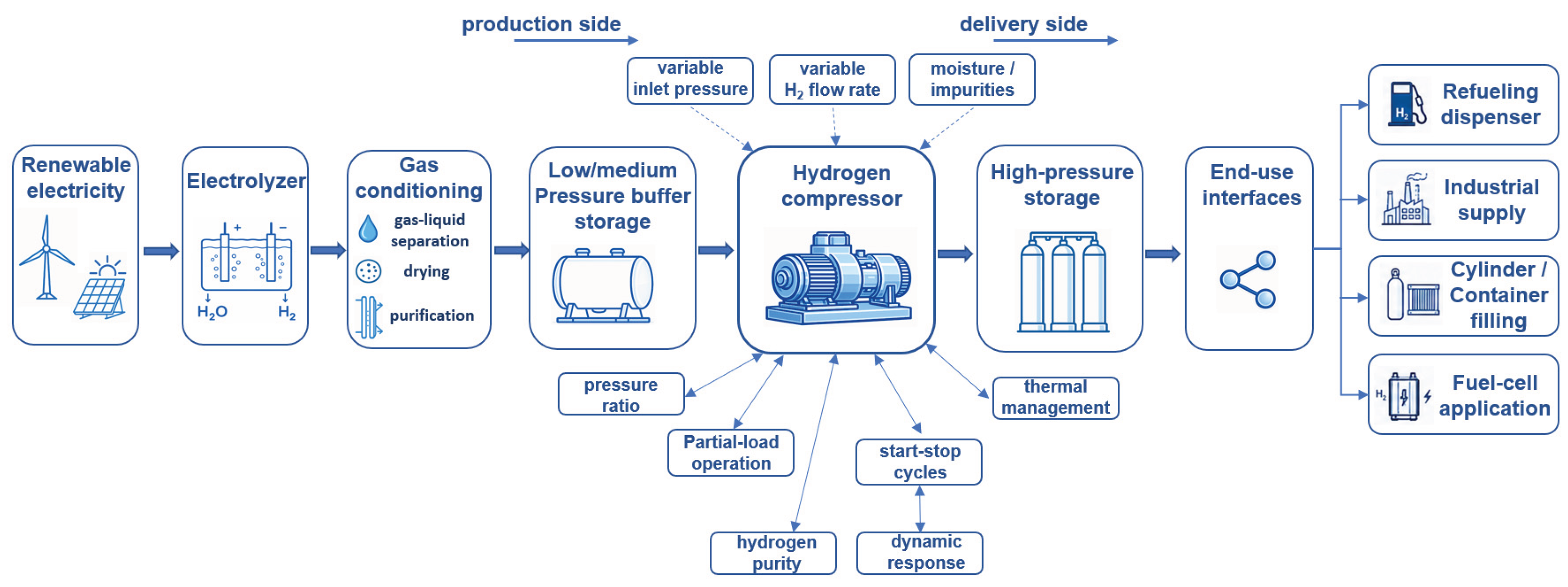
Figure 2.
Schematic representation of a single-stage reciprocating compressor [92].
Figure 2.
Schematic representation of a single-stage reciprocating compressor [92].
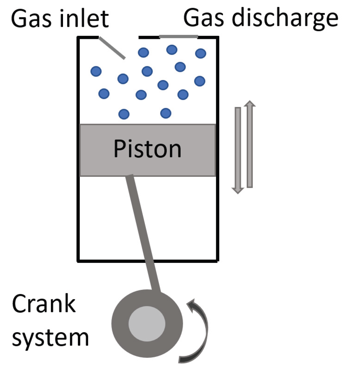
Figure 3.
Schematic operating principle of a hydraulically driven diaphragm compressor [92].
Figure 3.
Schematic operating principle of a hydraulically driven diaphragm compressor [92].
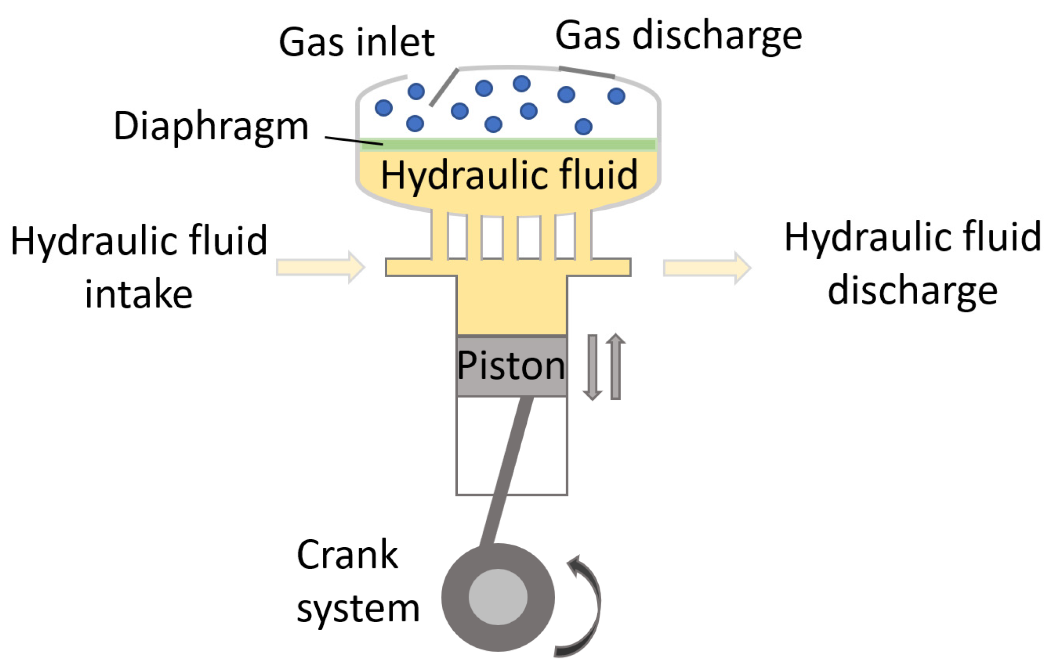
Figure 4.
Schematic representation of a two-stage, single-acting hydraulically driven piston compressor. The first-stage low-pressure hydrogen chamber is shown on the left and the second-stage high-pressure chamber on the right, with the hydraulic cylinder driving the central piston assembly. The arrows indicate the current directions of piston motion and fluid flow. During the reverse stroke, partially compressed hydrogen is transferred from the first stage to the second stage through the interstage gas line. Adapted from Ref. [139].
Figure 4.
Schematic representation of a two-stage, single-acting hydraulically driven piston compressor. The first-stage low-pressure hydrogen chamber is shown on the left and the second-stage high-pressure chamber on the right, with the hydraulic cylinder driving the central piston assembly. The arrows indicate the current directions of piston motion and fluid flow. During the reverse stroke, partially compressed hydrogen is transferred from the first stage to the second stage through the interstage gas line. Adapted from Ref. [139].
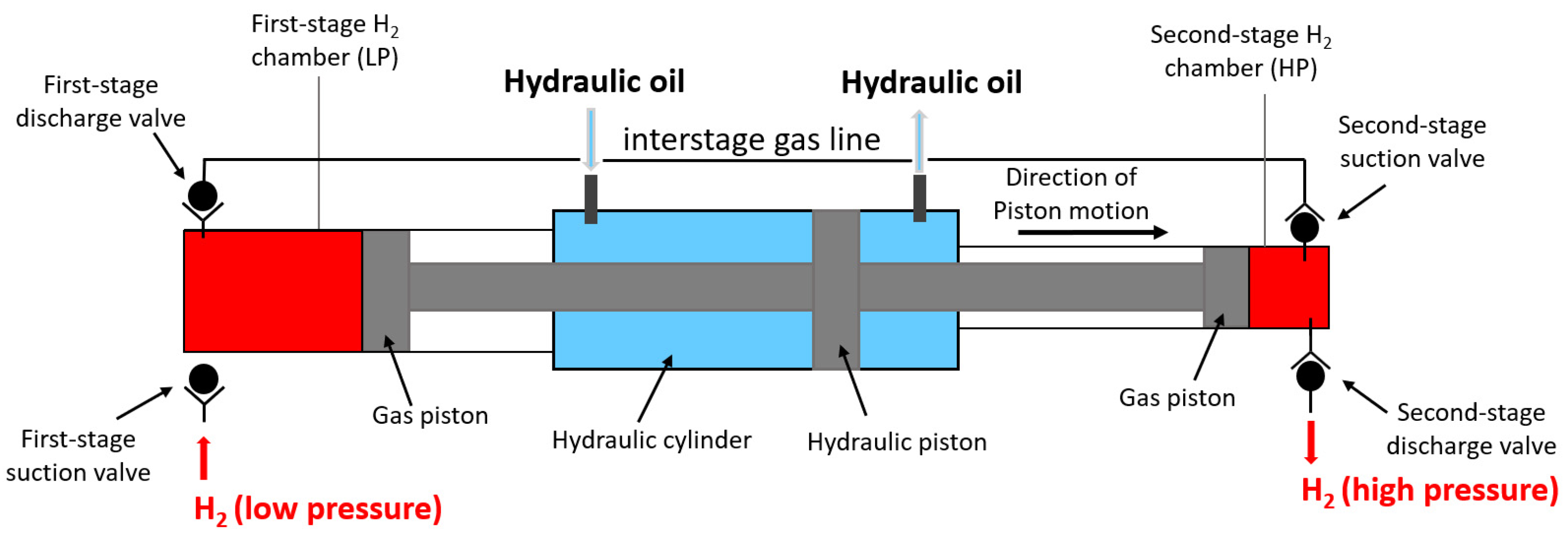
Figure 5.
Schematic operating principle of a centrifugal compressor. Adapted from Ref. [163].
Figure 5.
Schematic operating principle of a centrifugal compressor. Adapted from Ref. [163].
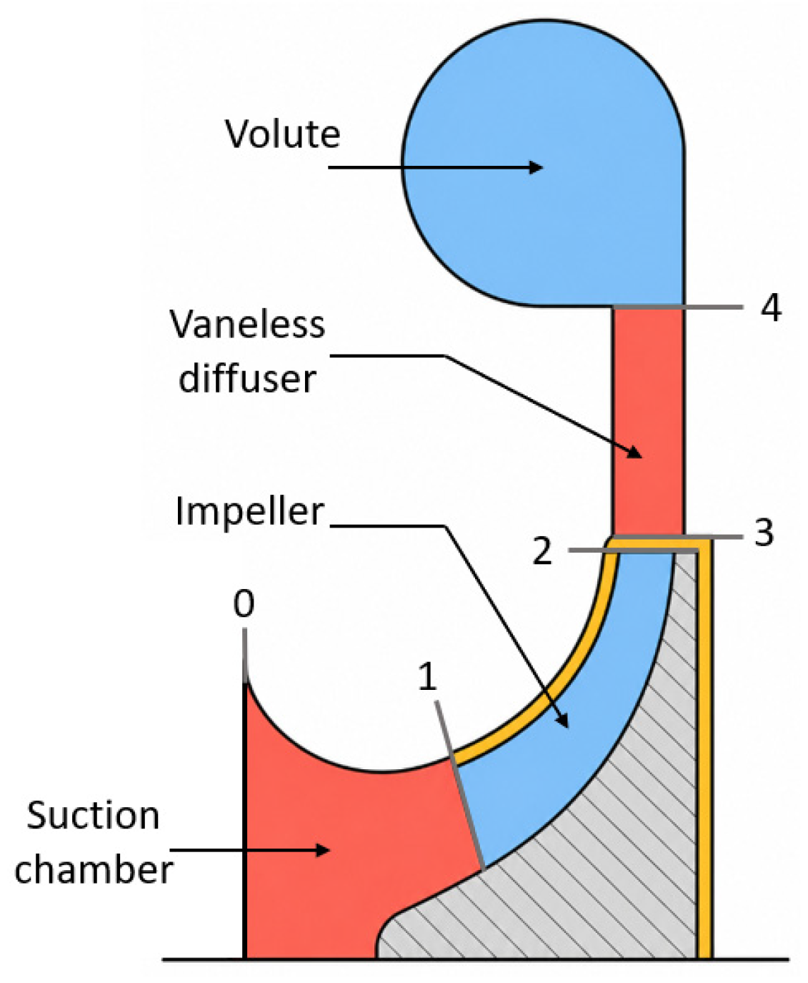
Figure 7.
Coupled design, operating and modeling factors affecting liquid-piston hydrogen compressor performance and their system-level implications.
Figure 7.
Coupled design, operating and modeling factors affecting liquid-piston hydrogen compressor performance and their system-level implications.
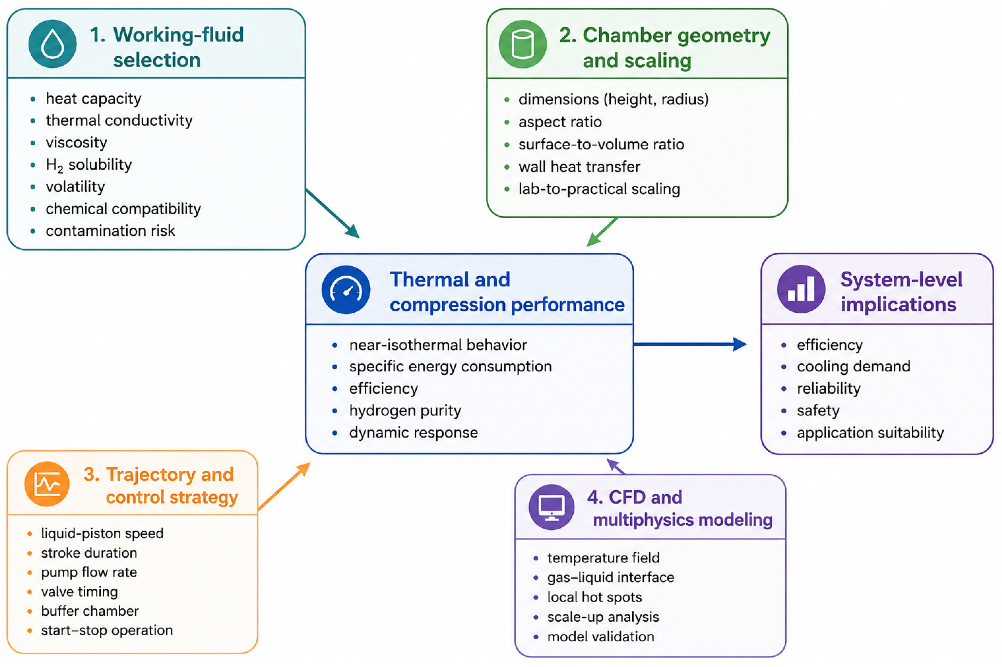
Figure 8.
Schematic operating principle of a PEM-based electrochemical hydrogen compressor. PEM—proton-exchange membrane; EHC—electrochemical hydrogen compressor; FC—fuel cell; EL—electrolyzer. Adapted from [279].
Figure 8.
Schematic operating principle of a PEM-based electrochemical hydrogen compressor. PEM—proton-exchange membrane; EHC—electrochemical hydrogen compressor; FC—fuel cell; EL—electrolyzer. Adapted from [279].
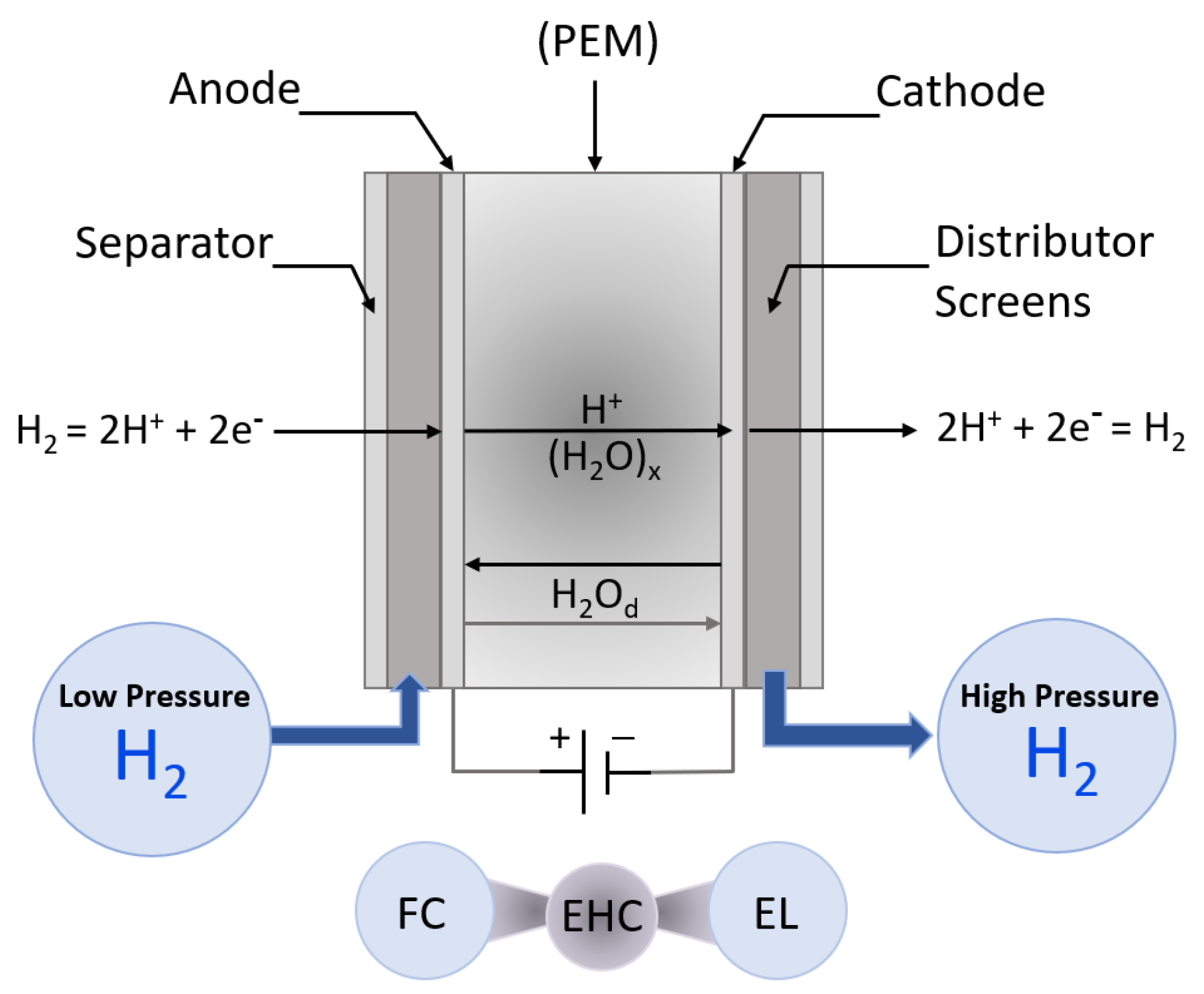
Figure 9.
Basic operating principle of a metal-hydride hydrogen compressor. Cooling promotes hydrogen absorption at lower pressure, whereas heat input drives hydrogen desorption at higher pressure [69,70,92].
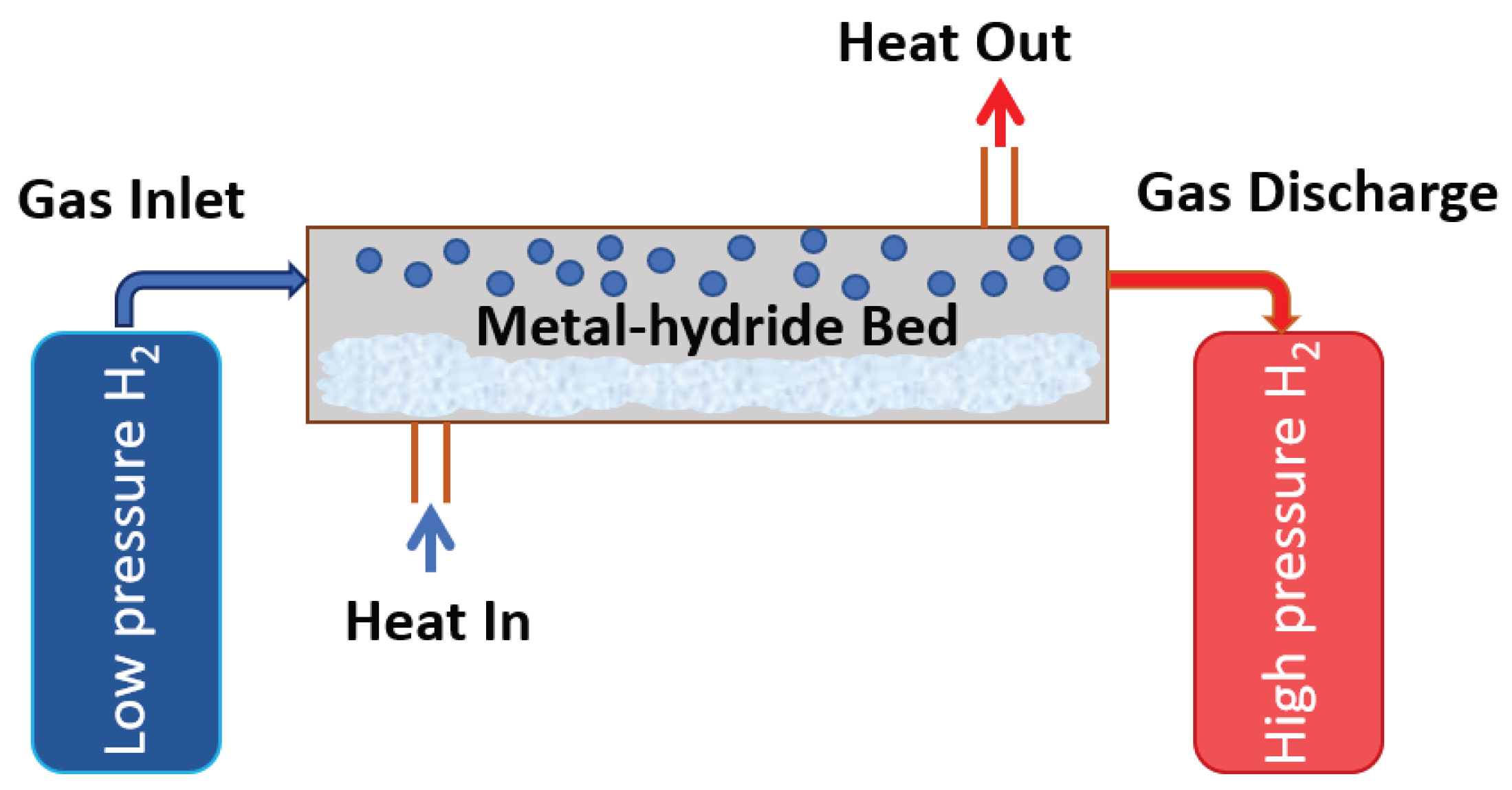

Table 1.
System role and technological challenges of hydrogen compression in hydrogen infrastructure.
Table 1.
System role and technological challenges of hydrogen compression in hydrogen infrastructure.
| Application context | Role of compression | Relevant technologies | Main challenges | Ref. |
| Hydrogen production and conditioning | Pressure boosting downstream of electrolysis or other hydrogen-production processes before storage or use | Mechanical, liquid-piston and electrochemical compressors | Variable inlet pressure and flow rate, moisture and impurities, integration with gas-conditioning units | [41,42,43,44,45] |
| Hydrogen storage and refueling stations | Compression to buffer and cascade-storage pressures and delivery of hydrogen for vehicle refueling | Reciprocating, diaphragm, hydraulically driven piston and ionic-liquid compressors | Energy consumption, gas heating, leakage, wear, high-pressure safety | [46,47,48,49,50,51,52,53] |
| Small decentralized green hydrogen systems | Matching variable local hydrogen production with storage and end-use pressure requirements | Liquid-piston, electrochemical, metal-hydride and compact mechanical compressors | Partial-load operation, frequent start-stop cycles, variable flow rate, compactness requirements | [54,55,56,57,58,59,60] |
| High-purity and fuel-cell-grade hydrogen | Compression without purity degradation or combined hydrogen purification and compression | Electrochemical, diaphragm and other oil-free mechanical compressors | Oil contamination, PEM fuel-cell sensitivity to impurities, water management | [61,62,63,64,65,66,67,68] |
| Heat-integrated industrial systems | Thermally driven pressure boosting and integration of compression with available low-grade or waste heat | Metal-hydride and hybrid compressors | Low hydride-bed thermal conductivity, slow kinetics, thermal-cycling degradation and heat-exchanger complexity | [69,70,71,72,73,74,75,76,77,78,79] |
Table 2.
Main criteria for evaluating hydrogen compression technologies.
| Criterion | Main indicators | Relevance for technology comparison |
| Pressure level and pressure ratio | Inlet pressure, outlet pressure, pressure ratio (pout/pin) | Determines compression work, number of stages, component loading and applicability to storage, refueling or industrial supply. |
| Thermodynamic compression path | Isothermal, adiabatic and polytropic behavior; gas temperature rise | Characterizes compression work and heat generation and enables assessment of the degree of near-isothermal operation. |
| Staging and cooling strategy | Number of stages, intercooling, heat rejection, cooling demand | Can reduce gas temperature rise and compression work but increases system complexity, footprint, cost and maintenance requirements. |
| Specific energy consumption | kWh/kg H2; compressor power and auxiliary energy demand | Directly affects operating cost and system efficiency; reported values must be interpreted together with the defined system boundary. |
| Compression efficiency | Isothermal, isentropic or polytropic efficiency; Faradaic efficiency for electrochemical systems | Enables comparison of performance when the efficiency definition, pressure ratio, temperature and flow conditions are clearly specified. |
| Hydrogen flow rate and capacity | Nominal flow rate, peak flow, minimum stable flow | Determines suitability for on-site electrolysis, refueling stations, industrial supply or small decentralized systems. |
| Hydrogen purity and contamination risk | Oil contamination, moisture, impurities, working-fluid carry-over, membrane crossover | Critical for PEM fuel cells and high-purity applications; compression may preserve, degrade or, in some technologies, improve gas quality. |
| Dynamic flexibility | Turndown ratio, part-load efficiency, response time, start-stop capability | Important for coupling with electrolyzers, variable renewable electricity and intermittent hydrogen demand. |
| Reliability and maintenance | Moving parts, seals, valves, membranes, working fluids, hydride degradation | Affects availability, service intervals, lifetime and practical deployability in decentralized systems. |
| Technology readiness and scalability | Technology readiness level, demonstrated pressure/flow range, commercial availability, scale-up potential | Indicates maturity and suitability for near-term deployment or future development. |
Table 3.
Advantages, limitations and technology-readiness considerations for liquid-piston hydrogen compressors.
Table 3.
Advantages, limitations and technology-readiness considerations for liquid-piston hydrogen compressors.
| Aspect | Main advantages | Main limitations / challenges | Relevance for technology readiness |
| Mechanical wear | Reduced need for gas-side piston rings, packing and sliding seals | Pumps, valves and other mechanical components remain subject to wear | Long-term durability under cyclic operation requires validation |
| Thermal behavior | Potential for reduced gas-temperature rise and near-isothermal operation | Performance depends strongly on working fluid, geometry, compression rate and heat-transfer conditions | Benefits must be demonstrated under representative pressure and flow conditions |
| Gas–liquid interface | Provides an additional heat-transfer pathway | Interface deformation, oscillations and liquid entrainment | Directly affects performance repeatability and cyclic reliability |
| Working fluid and hydrogen purity | Potentially low lubricant-related contamination | Vapor or droplet carry-over, hydrogen dissolution, fluid degradation and material compatibility | Critical for PEM fuel-cell-grade hydrogen and long-term operation |
| Hydraulic and control system | Controllable piston trajectory and flexible operation | Hydraulic losses, pumps, valves, reservoirs, sensors and control complexity | System-level efficiency and reliability must be demonstrated |
| Scaling | Favorable thermal performance can be achieved at laboratory scale | Scale-up may reduce heat-transfer effectiveness and increase hydraulic and structural requirements | Pilot- and larger-scale validation is needed |
| Experimental validation | Growing numerical and laboratory-scale evidence base | Limited long-term cyclic and field data | Technology readiness remains strongly configuration- and application-dependent |
Table 4.
Application-oriented cross-technology comparison of hydrogen compression technologies for decentralized green hydrogen infrastructure.
Table 4.
Application-oriented cross-technology comparison of hydrogen compression technologies for decentralized green hydrogen infrastructure.
| Technology | Pressure and flow role | Energy and thermal profile | Purity and dynamic operation | Main limitations and evidence |
| Reciprocating piston compressors | High-pressure; medium-to-high flow; suitable for hydrogen refueling station, storage filling and industrial supply | Mature multistage compression; intercooling and aftercooling commonly required at high pressure ratios | Dynamic operation possible, but frequent start–stop cycling increases wear; oil-free or dry-running designs preferred for high-purity H2 | Moving parts, seals, valves and lubrication/dry-running wear; commercially mature with broad field, experimental and techno-economic evidence |
| Diaphragm compressors | High-pressure; low-to-medium flow; widely used in HRS and cylinder filling | Mechanical/hydraulic compression; heat removal required from the compression head and hydraulic system | Well suited to high-purity H2 because of the separated gas path; moderate dynamic flexibility | Diaphragm fatigue, hydraulic-system management and valve wear; commercially mature with substantial field and experimental evidence |
| Hydraulically driven piston | High-pressure; low-to-medium flow; suitable for compact and intermittent high-pressure operation | Controlled hydraulic actuation, but hydraulic losses and cooling demand contribute to system energy use | Good controllability; hydrogen purity depends on reliable separation from the hydraulic circuit and sealing quality | Pumps, seals, valves and accumulators increase maintenance requirements; application-specific commercial and experimental evidence |
| Centrifugal | Large continuous flow; industrial supply, pipeline boosting and centralized production | Efficient near the design point; hydrogen service may require high rotational speed and/or multiple stages | Less suitable for small, strongly fluctuating systems; turndown constrained by surge and choke limits | Rotor dynamics, bearings, seals and multistage complexity; mature turbomachinery with hydrogen-specific applicability concentrated at larger scales |
| Liquid-piston compressors | Low-to-medium flow; promising for thermally optimized small- and medium-scale systems | Potential for reduced gas-temperature rise and near-isothermal operation under appropriate conditions; total energy depends strongly on hydraulic losses and auxiliaries | Potentially flexible through pump and trajectory control; purity affected by liquid carry-over, volatility and H2 dissolution | Interface stability, working-fluid selection, hydraulic complexity, scale-up and validation; lower commercial maturity with mainly numerical, laboratory and emerging pilot evidence |
| Ionic-liquid compressors | Low-to-medium flow; specialized liquid-based concept for H2 storage and refueling | Very low vapor pressure can limit vapor-phase contamination; viscosity and two-phase dynamics affect energy consumption | Potentially low vapor contamination; dynamic behavior depends strongly on gas–liquid interface and valve operation | Liquid waves, carry-over, viscosity, materials compatibility and cost; configuration-dependent maturity with numerical and experimental evidence |
| Electrochemical | Low-to-medium flow; attractive for compact and high-purity applications; pressure capability is configuration-dependent | Electrically driven compression; energy consumption depends on cell voltage, current density, pressure ratio and auxiliaries | Strong purification potential and electrically controlled throughput; performance depends on impurity tolerance and water management | Membrane durability, crossover, water management, catalyst sensitivity, stack mechanics and cost; growing experimental evidence but limited long-term field data |
| Metal-hydride compressors | Low-to-moderate flow; application-specific thermally driven compression | Uses thermal energy as the principal driving input; attractive where suitable low-grade or waste heat is available | Quiet operation and potential purification; relatively slow dynamic response | Sorption kinetics, low hydride-bed thermal conductivity, material degradation and heat-exchanger complexity; application-specific maturity with experimental and techno-economic evidence |
| Hybrid systems | System-specific; pressure and functional duties distributed among stages | Can allocate compression, purification, thermal management or heat-driven boosting to complementary technologies | Potentially high flexibility when stages and control strategy are properly matched | Additional valves, sensors, heat exchangers, power electronics and control complexity; emerging evidence base dominated by system studies, modeling and techno-economic assessment |
Table 5.
Application-oriented selection of hydrogen compression technologies for representative hydrogen-system configurations.
Table 5.
Application-oriented selection of hydrogen compression technologies for representative hydrogen-system configurations.
| Application/system context | Primary candidate(s) | Alternative/complementary option(s) | Main selection rationale | Main limitations |
| On-site electrolyzer system | Compact oil-free mechanical or electrochemical compressor | Liquid-piston compressor; hydraulically driven piston compressor | Integration with local hydrogen production and buffer storage; flexible pressure boosting downstream of electrolysis | Variable inlet flow and pressure, start–stop operation, moisture and purity management |
| Small decentralized H2 system | Electrochemical or liquid-piston compressor | Diaphragm compressor; metal-hydride compressor | Suitable for moderate flow rates, compact system integration and flexible operation | Limited throughput for some concepts, control sensitivity and limited long-term field data for emerging technologies |
| Hydrogen refueling station | Reciprocating, diaphragm or hydraulically driven piston compressor | Electrochemical compressor as a complementary stage; liquid-piston or ionic-liquid compressor | High-pressure capability and compatibility with cascade storage and dispensing | Wear and maintenance, cooling demand, diaphragm fatigue or hydraulic-system complexity |
| High-purity fuel-cell hydrogen | Electrochemical or diaphragm compressor | Oil-free reciprocating compressor; liquid-piston system with appropriate gas-cleaning measures | Low contamination risk and, for EHCs, potential simultaneous purification and compression | Membrane durability, water management and catalyst sensitivity for EHCs; diaphragm fatigue for diaphragm compressors |
| Industrial site with available waste heat | Metal-hydride compressor | Mechanical–metal-hydride or electrochemical–metal-hydride hybrid system | Utilization of low-grade or waste heat; quiet operation; potential high-purity hydrogen delivery | Slow sorption kinetics, hydride-bed heat transfer, material degradation and heat-exchanger complexity |
| Large continuous industrial hydrogen flow | Centrifugal/dynamic compressor or large reciprocating compressor | Multistage mechanical compression train; hybrid compression system | High flow-rate capability and suitability for continuous industrial operation | Less suitable for strongly fluctuating low-flow operation; surge/choke constraints for dynamic compressors |
Disclaimer/Publisher’s Note: The statements, opinions and data contained in all publications are solely those of the individual author(s) and contributor(s) and not of MDPI and/or the editor(s). MDPI and/or the editor(s) disclaim responsibility for any injury to people or property resulting from any ideas, methods, instructions or products referred to in the content. |
© 2026 by the authors. Licensee MDPI, Basel, Switzerland. This article is an open access article distributed under the terms and conditions of the Creative Commons Attribution (CC BY) license (http://creativecommons.org/licenses/by/4.0/).
Copyright: This open access article is published under a Creative Commons CC BY 4.0 license, which permit the free download, distribution, and reuse, provided that the author and preprint are cited in any reuse.