

Submitted:
09 September 2026
Posted:
10 September 2026
You are already at the latest version
Abstract
Thin-walled cold-formed C- and Z-sections are widely used in lightweight structural systems, where web openings are frequently introduced for service integration, weight reduction, or manufacturing requirements. However, local perforations alter not only the classical bending and shear stiffness but also torsional response, warping, and the coupling between generalized deformation modes. This study develops a reduced stiffness framework for perforated thin-walled members based on static condensation of detailed shell finite element models. Each perforated segment is first condensed to its boundary degrees of freedom (DOF) and subsequently projected onto an enriched beam-type kinematic basis comprising six classical rigid-section modes and an additional sectorial warping mode. The resulting reduced element is described by a compact stiffness matrix that preserves the energetic influence of local deformation around the opening while enabling efficient one-dimensional assembly of long perforated members. The effect of perforation is expressed through an opening-induced stiffness correction relative to the corresponding unperforated segment. A low-dimensional representation of this correction is further investigated using proper orthogonal decomposition (POD), allowing the dependence of the reduced stiffness matrix on opening geometry to be represented by a limited number of dominant stiffness modes. Only three POD modes were required to represent more than 99.9% of the snapshot energy of the combined C- and Z-section stiffness-correction database, while the surrogate reconstruction error of the complete correction matrix remained approximately 1.5% on average. At member level, the proposed seven-DOF formulation reduced the number of structural degrees of freedom by approximately 400–455 times while keeping displacement and twist profile errors below 3.2%.
Keywords:
cold-formed steel
; thin-walled sections
; web openings
; static condensation
; reduced-order modeling
; warping
; generalized beam element
; stiffness matrix
; proper orthogonal decomposition
; surrogate modeling
1. Introduction
Cold-formed thin-walled steel members offer a favorable strength-to-weight ratio, manufacturing flexibility, and high structural efficiency, which has led to their widespread use in building systems, storage structures, lightweight frames, and other engineering applications. In many practical configurations, C- and Z-sections contain web openings introduced for installation purposes, connections, weight reduction, thermal considerations, or technological requirements. Such perforations interrupt the otherwise prismatic geometry and may considerably alter the mechanical response of the member. Early investigations therefore focused primarily on the degradation of strength and stability caused by openings. Miller and Peköz [1] examined local buckling of perforated wall studs, while Shan et al. [2] and LaBoube et al. [3] investigated the interaction of bending, shear, and web openings in cold-formed C-sections. Davies et al. [4] subsequently addressed perforated sections subjected to combined axial loading and bending, highlighting the additional complexity introduced by regularly distributed holes.
A substantial part of the subsequent research has remained focused on strength-oriented representations of perforated members. The concept of an equivalent reduced web thickness was proposed as a practical means of representing regularly perforated channel sections [5], whereas detailed studies examined elastic buckling of plates with holes [6] and incorporated the influence of openings into the Direct Strength Method for cold-formed steel columns [7]. Web crippling and its interaction with perforations were investigated experimentally and numerically by Uzzaman et al. [8,9]. Alternative numerical approaches have also been developed for stability assessment, including finite-strip formulations for perforated rack columns [10] and thin-walled columns with repeated perforation patterns [11]. These investigations established that the influence of an opening cannot generally be represented solely by the loss of cross-sectional area, since its geometry and location affect local, distortional, and global deformation mechanisms.
Further work has therefore increasingly addressed interactions between perforation geometry and specific structural modes. Cai and Moen [12] employed Generalized Beam Theory (GBT) to investigate elastic buckling of members containing rectangular holes, while Wang and Young [13] studied the flexural behavior of built-up cold-formed sections with web perforations. Distortional buckling of channel beams with circular openings was analyzed by Yuan et al. [14], and the effects of edge-stiffened openings on compressed channel sections were investigated by Chen et al. [15]. Pham et al. [16] focused on shear strength and design of channels with web holes, whereas Yu et al. [17] examined distortional buckling under distributed transverse loading. More recent studies have continued this trend toward increasingly detailed treatment of perforation-induced instability and strength reduction, including analytical formulations for distortional buckling [18], combined compression and bending [19], and web-perforated lipped channels [20]. The broad scope of current research in this field has recently been summarized by Zeng et al. [21], confirming that strength, buckling, and ultimate resistance remain the dominant topics in studies of perforated cold-formed members.
An important parallel development concerns reduced one-dimensional representations capable of reproducing complex thin-walled behavior at substantially lower computational cost than detailed shell models. GBT provides an especially powerful framework because global, local, distortional, and warping deformation modes can be introduced explicitly into a beam-type description [22,23]. Its extension to perforated members has led to several sophisticated formulations. Bonada et al. [24] incorporated perforation effects into geometrically nonlinear GBT analysis of rack columns, while Duan and Zhao [25] developed an extended first-order GBT formulation in which enrichment functions describe displacement discontinuities associated with arbitrary holes. This framework was subsequently extended to linear buckling [26], elastoplastic analysis [27], edge-stiffened openings [28], and, most recently, large-deformation analysis [29]. Dynamic behavior of perforated rack members has also been successfully treated within the GBT framework [30]. These approaches demonstrate that advanced beam theories can retain much of the mechanical richness of shell models while significantly reducing the number of degrees of freedom.
A different reduction philosophy consists of deriving an equivalent one-dimensional description directly from a detailed numerical model rather than prescribing a specialized analytical representation of the perforation. Static condensation, originating from classical matrix reduction concepts [31], provides a natural basis for such an approach because internal degrees of freedom can be eliminated while preserving the force–displacement relationship at selected interfaces. Shell-to-beam numerical homogenization has previously been used to determine equivalent stiffnesses of thin-walled perforated beams [32] and subsequently combined with parametric optimization and soft-computing techniques [33]. Related studies demonstrated that the same energy-equivalence philosophy can accommodate local geometric imperfections [34], perforation and creasing in layered structures [35], and non-classical shear effects that are difficult to estimate using elementary sectional formulas [36]. These results suggest that detailed local mechanics can be transferred effectively to computationally inexpensive structural representations without explicitly deriving separate analytical correction factors for each deformation mechanism.
Other recent approaches also point toward homogenized or equivalent descriptions of perforated members. Dong et al. [37], for example, proposed a homogenized model accounting for the enhanced shear deformation of perforated steel beams and demonstrated that opening geometry can be incorporated through equivalent stiffness measures. However, equivalent sectional properties such as , , , or characterize individual deformation mechanisms separately and may not retain the complete coupling structure of an arbitrary perforated thin-walled segment. This limitation becomes particularly relevant for open C- and Z-sections, where shear, bending, torsion, and cross-sectional warping may interact and where the presence of a web opening may modify not only individual stiffness terms but also their mutual couplings.
The present study therefore adopts a different perspective. Rather than deriving isolated effective sectional properties or introducing the perforation directly into a predefined beam theory, a detailed shell segment containing an opening is first reduced by static condensation to its end interfaces. The condensed response is then projected onto a beam-type kinematic basis enriched by a sectorial warping mode, resulting in a compact element stiffness matrix . Consequently, the local shell deformation around the opening is retained energetically in a generalized one-dimensional element that can subsequently be assembled in the same manner as conventional finite elements. The perforation effect is expressed through an opening-induced stiffness correction, , with respect to the corresponding unperforated segment.
A further objective is to determine whether this matrix correction possesses an intrinsically low-dimensional structure. Proper orthogonal decomposition (POD) has proven effective in reducing parametrically varying structural systems [38] and in constructing reduced representations of modular structures whose independently generated substructures are subsequently assembled [39]. Here, POD is applied not to displacement snapshots but to dimensionless stiffness-correction matrices. If only a limited number of dominant matrix modes is required, the geometry-dependent reduced stiffness can be reconstructed from a small set of modal coefficients, which may subsequently be predicted using a lightweight surrogate model. The resulting framework establishes a direct path from detailed shell mechanics to a warping-enriched beam model whose element stiffness can be rapidly adapted to different opening geometries and assembled into long perforated C- and Z-section members. This provides the basis for computationally efficient structural analysis while preserving the essential stiffness modifications and coupling effects induced by web perforations.
2. Materials and Methods
The proposed formulation replaces a detailed shell representation of a perforated thin-walled segment by a compact one-dimensional finite element whose stiffness matrix retains the energetic influence of the opening, including bending, shear, torsion, cross-sectional warping, and the couplings between these deformation mechanisms. The method is formulated for cold-formed C- and Z-sections, although the reduction procedure itself is not restricted to these cross-sectional families. A local Cartesian system -- is adopted, with aligned with the member axis and and lying in the cross-sectional plane. The reference point of each intact end section is located at the centroid of the corresponding unperforated cross-section. The same reference system is used for the perforated and unperforated segments so that the resulting stiffness matrices can be compared componentwise.
A computational segment of length contains one web opening and is bounded by two intact cross-sections, denoted by and . For regularly perforated members, is equal to the opening pitch , and the opening is placed at the center of the segment. For non-uniform perforation patterns, the interfaces may be positioned at any intact cross-sections between adjacent openings, provided that the same interface definition is used in the detailed and reduced models. Figure 1 illustrates the adopted segment, coordinate system, opening parameters, and end interfaces. The geometric notation used throughout the formulation is summarized in Table 1.
Unless stated otherwise, the numerical analyses were performed for lipped C- and Z-sections with mm, mm, mm, and mm. The reduced-element length was mm. The material was assumed to be linear elastic with GPa and . The same nominal dimensions were adopted for the C- and Z-section families so that differences in the reduced response resulted from cross-sectional arrangement rather than from changes in gross dimensions.
Unless stated otherwise, the numerical analyses were performed for lipped C- and Z-sections with mm, mm, mm, and mm. The reduced-element length was mm. The material was assumed to be linear elastic with GPa and . The same nominal dimensions were adopted for the C- and Z-section families so that differences in the reduced response resulted from cross-sectional arrangement rather than from changes in gross dimensions.
The geometry of an opening is represented by a dimensionless parameter vector. For a fixed cross-sectional family, a convenient generic description is
where parameters that are not relevant to a particular opening family are omitted. Opening shape is treated as a categorical variable rather than assigned an artificial numerical distance. Consequently, when several discrete opening families are investigated, separate surrogate mappings are constructed for each opening family and for each section family, whereas the reduction procedure remains identical. This also permits direct comparison of the reduced stiffness operators obtained for C- and Z-sections.
The material is assumed to be homogeneous, isotropic, and linearly elastic. Because the objective is the identification of elastic stiffness rather than resistance, yielding, residual stresses, geometrical imperfections, and material nonlinearities are excluded. The detailed models were discretized using four-node flat shell elements with six degrees of freedom per node. The formulation combined in-plane membrane behavior with Reissner–Mindlin bending, MITC4-type assumed transverse shear interpolation, and weak drilling-rotation stabilization. Mesh refinement was concentrated around the opening boundary and at geometrical transitions. Mesh convergence was assessed using the complete reduced stiffness matrix rather than a single displacement quantity; the adopted discretization was required to differ from the finest reference solution by less than 1% in the Frobenius norm of the dimensionless reduced stiffness matrix.
For a given detailed segment, the linear finite element equilibrium equations are written as
where is the assembled shell stiffness matrix, is the vector of nodal degrees of freedom, and is the corresponding nodal force vector. The degrees of freedom are partitioned into retained interface translations, denoted by , and eliminated degrees of freedom . Importantly, only the three translational degrees of freedom of the nodes located on are retained. All remaining degrees of freedom, including the rotational shell degrees of freedom at the interfaces, are included in . This choice avoids prescribing an artificial shell-director rotation at the reduced interfaces and allows the local shell rotations to relax consistently with the imposed translational interface kinematics. The partitioned system is therefore
where no external forces are applied to the eliminated internal degrees of freedom during the reduction. Static condensation [31] gives the exact interface stiffness associated with the retained translations,
so that . In the numerical implementation, the inverse in Equation (4) is not formed explicitly; the required products are obtained by solving linear systems with . The condensation preserves the exact static force-displacement relation at the retained interface translations. At this stage, no beam assumption has yet been introduced and still allows arbitrary translational deformation patterns of both end cross-sections.
The second reduction step introduces a compact beam-type interface basis. Six classical rigid-section modes are augmented by one sectorial warping mode. The warping function is determined once for the corresponding unperforated C- or Z-section and is subsequently kept fixed for all perforated variants of that cross-sectional family. This is possible because the end interfaces are located at intact cross-sections. The local shell field inside the segment remains unconstrained and is therefore free to develop opening-induced bending, shear deformation, local distortion, and non-classical warping.
The preliminary sectorial coordinate , defined along the mid-line coordinate of the thin-walled cross-section, is evaluated from
with and measured from the adopted cross-sectional reference point. Since the sectorial coordinate is defined up to additive rigid and linear components, it is orthogonalized with respect to the axial-extension and the two bending fields. The corrected warping function is written as
where , , and are selected such that
The three coefficients can be obtained directly from the small linear system
where the area integrals are evaluated over the thin-walled cross-section, equivalently as thickness-weighted line integrals along its mid-line. Orthogonalization in Equations (6)-(8) prevents the warping coordinate from duplicating the constant axial or linear bending modes. A consistent sign convention is enforced for all models by requiring the value of at a selected reference flange tip to be positive. Figure 2 summarizes the static-condensation stage preceding the projection onto the generalized interface basis.
At each end of the segment, the generalized displacement vector is defined as
where , , and are translations of the reference point, , , and are cross-sectional rotations, and is the amplitude of the sectorial warping mode. Since , the warping amplitude has dimension , ensuring that has the dimension of displacement. The formulation does not impose the classical Vlasov relation between and the spatial derivative of twist inside the reduced segment; instead, is treated as an independent interface coordinate. The relation between torsional rotation, warping, and the corresponding generalized forces is therefore inherited directly from the condensed shell stiffness.
For an interface node located at , the translational displacement is expressed as
which combines rigid translation, rigid cross-sectional rotation, and axial sectorial warping. The matrices are assembled for all translational degrees of freedom at a given interface to obtain and . For the complete two-ended segment,
where . The strain energy stored in the statically condensed shell segment is
and energy equivalence immediately yields the reduced element stiffness matrix
with . Equation (13) is the central shell-to-beam reduction used in this study. For comparison, a classical six-degree-of-freedom interface model is obtained simply by deleting the warping column from and , leading to a element matrix. Table 2 summarizes both reduced kinematic bases. Their comparison provides a direct quantitative measure of the improvement associated with the single additional warping coordinate.
Although Equations (2)-(13) are written in terms of explicit shell stiffness matrices, direct access to the complete assembled matrix is not required. An equivalent implementation can identify through a sequence of unit generalized-displacement analyses. If denotes the -th unit vector in the 14-dimensional generalized coordinate space, the boundary translations are prescribed, the shell problem is solved with all internal degrees of freedom free to equilibrate, and the resulting interface reactions are projected back to generalized forces according to
The reduced stiffness matrix is then assembled columnwise as
This unit-displacement implementation is mathematically equivalent to Equations (4) and (13) for a linear elastic problem and is convenient when commercial FE software does not provide straightforward access to the assembled stiffness matrix. Figure 3 summarizes both equivalent computational routes.
For every perforated segment, a geometrically identical reference segment without an opening is reduced using the same interfaces, mesh convention, reference system, and warping basis. Its stiffness matrix is denoted by . The mechanical influence of the opening is represented by the signed stiffness-correction operator
so that . Using the correction rather than the total matrix separates the known stiffness of the prismatic unperforated segment from the geometry-dependent perturbation produced by the opening and substantially improves the numerical conditioning of the subsequent reduced-order representation.
Because the generalized coordinates have different physical dimensions, POD must not be applied directly to the raw entries of . A dimensionless energetic scaling is therefore introduced. With the characteristic length , the scaling matrix for one end is
such that , where is dimensionless. Using as the reference energy scale, where is the gross area of the unperforated cross-section, the dimensionless stiffness matrix is defined as
This transformation ensures that all components entering the data reduction are dimensionless and energetically comparable.
A proper orthogonal decomposition is then used to investigate whether the opening-induced matrix correction occupies a low-dimensional subspace. POD is evaluated both separately for the C- and Z-section datasets and jointly for the combined C+Z database. The separate decompositions quantify section-specific compressibility, whereas the combined decomposition provides the common reduced basis subsequently adopted in the surrogate models. Separate surrogate mappings are constructed for the C- and Z-section families. For each sampled geometry , the independent entries of the symmetric matrix are mapped to a vector using the symmetric vectorization operator , in which off-diagonal terms are multiplied by . This convention preserves the matrix Frobenius norm under vectorization. Thus,
for the proposed element. For sampled geometries, the stiffness-correction vectors are collected directly in the snapshot matrix
No mean subtraction is applied because the zero correction has a direct mechanical meaning and corresponds to the unperforated reference segment. The singular value decomposition is therefore performed as
The number of retained modes is selected from
The POD coordinates associated with sample are
and the corresponding rank- reconstruction is
Here, contains the first POD stiffness-correction modes. For matrix representation, the -th POD stiffness-correction mode is defined as , so that .
Figure 4.
Low-dimensional representation of the opening-induced stiffness correction: geometry sampling, shell reduction, dimensionless matrix correction, symmetric vectorization, POD, surrogate prediction of modal coefficients, and reconstruction of .
Figure 4.
Low-dimensional representation of the opening-induced stiffness correction: geometry sampling, shell reduction, dimensionless matrix correction, symmetric vectorization, POD, surrogate prediction of modal coefficients, and reconstruction of .
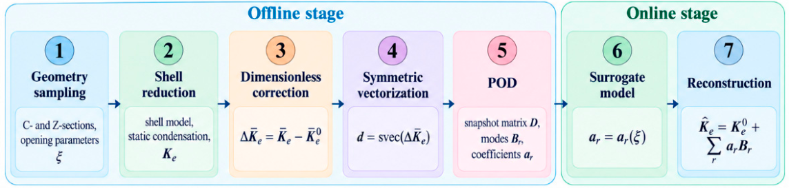
The dependence of the POD coordinates on the opening geometry is represented using Gaussian process regression (GPR). Separate surrogate models are constructed for the C- and Z-section families and for each retained POD coefficient. In the present study, the surrogate database consists of the same 12 rectangular-opening geometries per section family used in the POD analysis, corresponding to and . For each validation fold, the two input variables and the corresponding POD coefficient are standardized using only the statistics of the current training subset. A squared-exponential kernel with automatic relevance determination is adopted,
where is the signal amplitude, are the characteristic length scales, and is the regularization parameter used in Equation (26). For a new geometry , the predicted coefficient is
where is the kernel matrix of the training inputs, is the kernel vector between the new input and all training samples, and contains the training values of the -th POD coordinate. Hyperparameters are obtained by maximizing the marginal likelihood. Predictive accuracy is assessed by leave-one-out cross-validation. For each section family and each POD coefficient, one of the 12 geometries is excluded, the GPR model is trained using the remaining 11 samples, and the excluded coefficient is subsequently predicted. This procedure is repeated for all geometries. The predictions reported in following Figures, and Tables therefore represent pooled out-of-sample leave-one-out results. Accordingly, the reported leave-one-out errors assess GPR prediction conditional on the fixed POD basis; the POD basis itself is not recomputed within individual validation folds.
For an unseen opening geometry, the predicted correction vector is reconstructed as
After applying the inverse symmetric-vectorization operator, the dimensionless element stiffness is obtained from
and the dimensional matrix used in structural calculations follows as
Symmetry is preserved exactly by the representation. Physical admissibility is additionally checked by fixing all generalized degrees of freedom at one end and verifying that the resulting dimensionless stiffness block is positive definite. Surrogate predictions are used only inside the sampled geometrical domain; a violation of this stability condition triggers evaluation of the corresponding detailed shell model rather than extrapolation.
The reduced matrices are subsequently assembled in the same manner as conventional finite elements. Adjacent perforated segments share the seven generalized coordinates at their common intact cross-section, including the warping amplitude . For element , let denote the Boolean connectivity matrix and the local-to-global coordinate transformation. The global reduced stiffness is
For straight C- and Z-members aligned with the global axis, reduces to the identity matrix. The generalized force vector work-conjugate to the seven nodal coordinates is written as
where is the generalized bimoment associated with . Free warping at an external end is a natural boundary condition corresponding to , whereas fully restrained warping is imposed by . Figure 5 shows the assembly of a long perforated member from geometry-dependent reduced elements and illustrates the treatment of the shared warping degree of freedom.
Validation is performed at three levels. First, the influence of the interface enrichment is assessed by comparing the B6 and B7 models with a detailed shell model for load cases dominated by bending, shear, torsion, and combined bending-torsion. This comparison establishes whether one sectorial warping mode is sufficient for the investigated C- and Z-sections. Second, POD/GPR predictions are evaluated for geometries excluded from the training set by comparing the predicted and directly condensed element matrices. Third, complete members containing multiple openings are analyzed both with an unconstrained detailed shell model and with an assembly of reduced elements. The latter validation is essential because the internal cross-sections of the detailed model are not forced to follow the seven-mode interface basis; consequently, agreement at member level directly tests whether the selected reduced kinematics is sufficiently rich to transfer the opening-induced local mechanics along the structure. The principal validation cases are summarized in Table 3.
For quantitative comparison of surrogate-predicted and directly condensed stiffness corrections, the relative Frobenius error is defined as
Because matrix agreement alone does not guarantee identical structural behavior, an energy-based error is evaluated for prescribed generalized displacement states,
For comparison with the full shell member, translational shell displacements extracted at selected intact cross-sections are projected onto the seven-dimensional interface basis using a weighted least-squares projection,
where is a diagonal matrix of nodal tributary-area weights. This projection permits direct comparison of the shell response with the generalized displacement vector of the reduced model without artificially constraining the shell cross-section. The corresponding relative generalized-displacement error over all inspected sections is
while the global strain-energy discrepancy is evaluated analogously to Equation (33). Together, the matrix, energy, and structural-response measures distinguish three possible sources of error: truncation of the interface kinematic basis, POD truncation, and surrogate prediction. This separation is important because the static condensation itself is exact for the retained interface translations, whereas approximation enters only through the subsequent interface projection and the low-dimensional prediction of the geometry-dependent stiffness correction.
3. Results
The results were organized to assess the proposed framework at four successive levels: (i) numerical consistency of the shell model and the interface reduction, (ii) ability of the reduced element to reproduce the stiffness of individual perforated segments, including warping effects, (iii) low-dimensional representation and prediction of the opening-induced stiffness correction, and (iv) accuracy and computational efficiency of structural models assembled from the reduced elements. The same sequence was applied to both C- and Z-sections so that the influence of cross-sectional asymmetry and stiffness coupling could be assessed consistently.
3.1. Numerical Convergence and Accuracy of the Reduced Element
The numerical convergence of the reduced stiffness matrix was first examined for the unperforated and perforated C-section. Four progressively refined shell meshes were considered, and the finest discretization was adopted as the reference solution. The relative error was evaluated using the Frobenius norm of the complete reduced stiffness matrix.
Figure 6.
Mesh-convergence characteristics: (a) relative error of the complete reduced stiffness matrix for the solid and representative perforated C-section; (b) convergence of selected generalized energetic stiffness measures for the representative perforated C-section.
Figure 6.
Mesh-convergence characteristics: (a) relative error of the complete reduced stiffness matrix for the solid and representative perforated C-section; (b) convergence of selected generalized energetic stiffness measures for the representative perforated C-section.
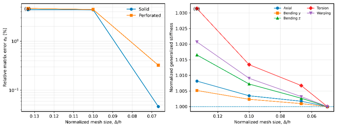
For the unperforated section, refinement from and to and reduced the matrix error from 4.37% to only 0.046%. For the representative perforated section with , the corresponding error decreased from 4.45% to 0.324%. Selected energetic stiffness measures converged at a similar rate. At the third mesh level, the deviations from the finest solution were approximately 0.17% for axial stiffness, 0.09–0.27% for bending-related measures, 0.67% for torsion, and 0.32% for warping. The third mesh level therefore provided a suitable compromise between accuracy and computational cost and was used in the subsequent parametric analyses unless stated otherwise.

Table 4.
Mesh-convergence study for the reference and representative perforated segments.
| Model | Mesh | Nodes | Shell elements | Shell DOFs | Relative error of[%] | ||
| Solid C-section | 1 | 0.1333 | 0.1000 | 299 | 264 | 1,794 | 4.406 |
| Solid C-section | 2 | 0.1000 | 0.0667 | 578 | 528 | 3,468 | 4.372 |
| Solid C-section | 3 | 0.0667 | 0.0500 | 1,075 | 1,008 | 6,450 | 0.046 |
| Solid C-section | 4 | 0.0500 | 0.0333 | 2,145 | 2,048 | 12,870 | Reference |
| Perforated C-section | 1 | 0.1333 | 0.1000 | 284 | 240 | 1,704 | 4.668 |
| Perforated C-section | 2 | 0.1000 | 0.0667 | 606 | 540 | 3,636 | 4.454 |
| Perforated C-section | 3 | 0.0667 | 0.0500 | 998 | 912 | 5,988 | 0.324 |
| Perforated C-section | 4 | 0.0500 | 0.0333 | 2,088 | 1,960 | 12,528 | Reference |
The influence of the interface treatment and of the additional warping coordinate was subsequently examined using several independent loading modes. The comparison included formulations retaining either three translational shell degrees of freedom or all six shell degrees of freedom at each interface node, followed by projection onto either a six- or seven-DOF generalized basis. For each loading mode, the reported error is the relative strain-energy discrepancy defined in Equation (33); the mean energy error is the arithmetic mean over the five considered deformation states.
Table 5.
Influence of interface representation and warping enrichment on reduced-element accuracy.
| Interface shell DOFs per node | Generalized DOFs per reduced node | Axial error [%] | Major-axis bending error [%] | Minor-axis bending error [%] | Torsional error [%] | Bending–torsion error [%] | Mean energy error [%] |
| 3 | 6 | 2.267 | 1.067 | 1.892 | 97.414 | 97.154 | 39.959 |
| 3 | 7 | 2.267 | 0.942 | 1.892 | 1.665 | 1.643 | 1.682 |
| 6 | 6 | 2.285 | 1.092 | 1.916 | 97.417 | 97.157 | 39.974 |
| 6 | 7 | 2.285 | 0.987 | 1.916 | 23.521 | 23.448 | 10.431 |
For axial and bending-dominated deformation, all four variants provided errors of approximately 1–2%. A fundamentally different behavior was observed in torsion. The six-DOF reduced model produced torsional errors of approximately 97%, independently of whether three or six shell degrees of freedom were retained at the interface. The omission of the sectorial warping coordinate effectively suppresses the longitudinal warping deformation at successive reduced interfaces and therefore results in a strongly over-stiff torsional response.
Introducing the seventh generalized degree of freedom reduced the torsional error to 1.67% when only translational shell degrees of freedom were retained. In contrast, retaining the shell rotations at the interface still resulted in a torsional error exceeding 23%. The latter result confirms that shell nodal rotations should remain internal variables and be eliminated during static condensation rather than directly constrained by the beam-type kinematic basis.
The effect becomes particularly clear for a member consisting of six perforated segments subjected to a pure end torque. The member consisted of six m segments, giving m, and was subjected to an end torque kNm. Classical generalized motions were restrained at the left end, while the warping coordinate was either left free or set to zero to obtain the free- and restrained-warping cases, respectively. Both free- and restrained-warping boundary conditions were examined.
Figure 7.
Influence of warping enrichment on torsional response: (a) free-warping case; (b) restrained-warping case. The full shell solution is compared with the six-DOF and seven-DOF reduced formulations.
Figure 7.
Influence of warping enrichment on torsional response: (a) free-warping case; (b) restrained-warping case. The full shell solution is compared with the six-DOF and seven-DOF reduced formulations.
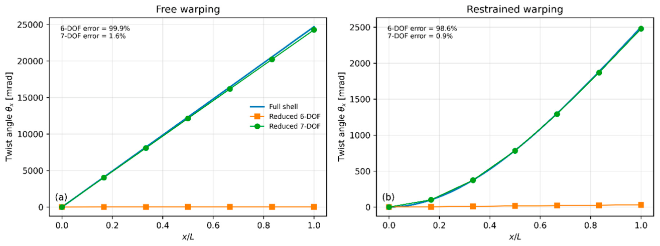
For free warping, the six-DOF model differed from the full shell solution by 99.87%, whereas the seven-DOF formulation reduced this discrepancy to 1.65%. Under restrained warping, the corresponding errors were 98.61% and 0.95%, respectively. The additional sectorial coordinate is therefore essential for representing the torsional response of perforated open thin-walled sections.
3.2. Reduced Stiffness Matrices and Opening-Induced Stiffness Modification
The influence of a web opening was next examined directly at the matrix level. The reduced stiffness matrix of each perforated segment was compared with the corresponding unperforated reference through the dimensionless correction
For a centered rectangular opening with and , the relative Frobenius norm of the stiffness correction reached 28.45% for the C-section and 28.06% for the Z-section. The correction was clearly non-uniform across the matrix, demonstrating that a perforation cannot be represented accurately by a single scalar reduction factor. Instead, the opening modifies individual stiffness contributions and generalized couplings to different degrees.
The global magnitude of the opening-induced correction for several representative opening geometries is summarized in Table 6.
For the representative centered rectangular opening, the global correction magnitude was almost identical for both section families, reaching 28.45% for the C-section and 28.06% for the Z-section, although Figure 8 shows that the distribution of individual matrix contributions differed between the two cross-sections.
The sensitivity to opening height was then investigated for centered rectangular openings at constant .
Figure 9.
Effect of normalized opening height on the reduced stiffness response of C- and Z-sections at : (a) major-axis bending-related stiffness; (b) transverse-shear-related stiffness; (c) torsional and warping-related stiffness; (d) normalized off-diagonal coupling norm.
Figure 9.
Effect of normalized opening height on the reduced stiffness response of C- and Z-sections at : (a) major-axis bending-related stiffness; (b) transverse-shear-related stiffness; (c) torsional and warping-related stiffness; (d) normalized off-diagonal coupling norm.
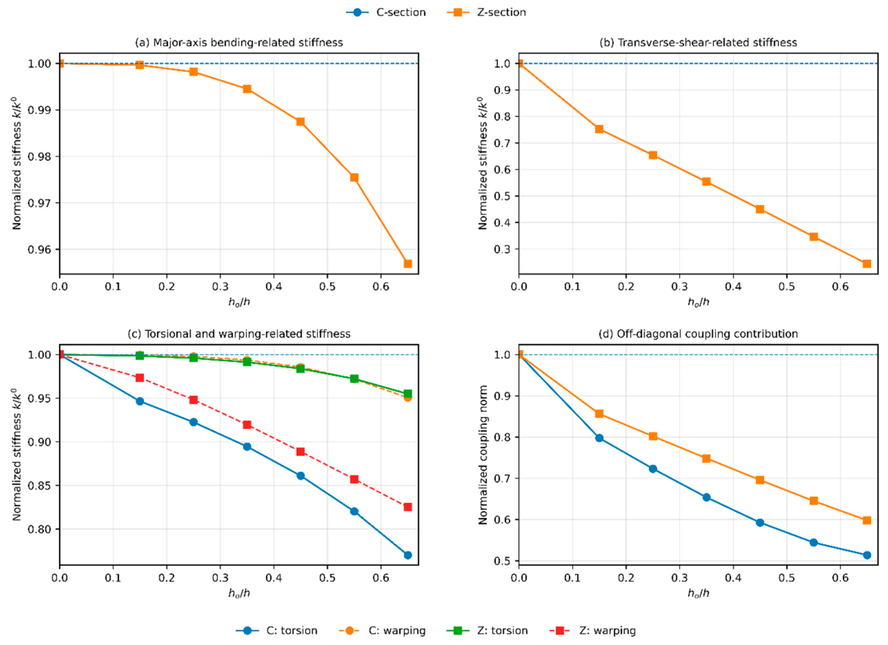
Increasing primarily affected the shear-related response. At , the normalized transverse-shear stiffness measure decreased to approximately 0.244 for both section types, whereas the bending-related measure remained close to 0.957. The torsional response showed a stronger dependence on cross-section type. For the C-section, the normalized torsional measure decreased to 0.770, while the Z-section retained a value of approximately 0.955. Conversely, the warping-related measure decreased more strongly for the Z-section, reaching 0.825 compared with 0.951 for the C-section. The normalized magnitude of the off-diagonal coupling terms also decreased substantially, to approximately 0.514 and 0.598 for C- and Z-sections, respectively.
A complementary analysis was performed by varying the longitudinal opening dimension while maintaining .
Figure 10.
Effect of normalized opening length on the reduced stiffness response of C- and Z-sections at : (a) major-axis bending-related stiffness; (b) transverse-shear-related stiffness; (c) torsional and warping-related stiffness; (d) normalized off-diagonal coupling norm.
Figure 10.
Effect of normalized opening length on the reduced stiffness response of C- and Z-sections at : (a) major-axis bending-related stiffness; (b) transverse-shear-related stiffness; (c) torsional and warping-related stiffness; (d) normalized off-diagonal coupling norm.
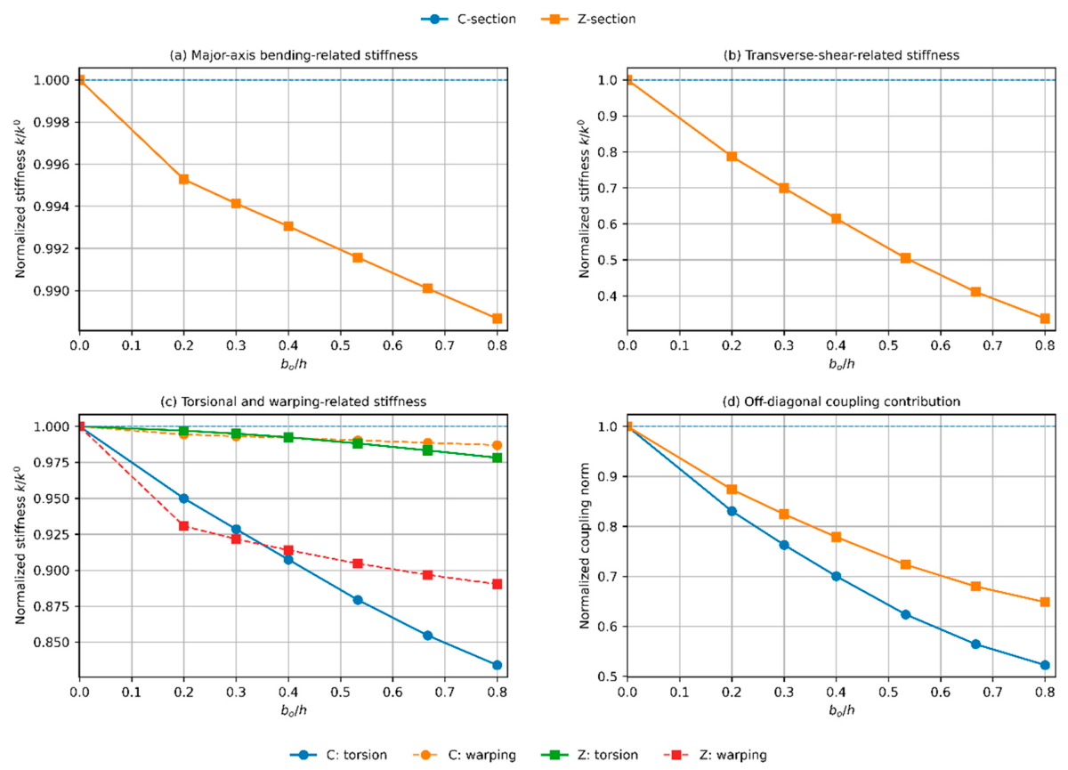
At , the bending-related measure remained above 0.988 for both sections, whereas the shear-related stiffness decreased to approximately 0.337. For the C-section, the torsional measure decreased to 0.834, while the corresponding Z-section value remained close to 0.978. The opposite tendency was again observed for the warping-related contribution, which remained at 0.987 for the C-section but decreased to 0.890 for the Z-section. Hence, opening height and opening length influence different components of the generalized stiffness matrix, with transverse shear being consistently the most sensitive contribution.
3.3. Low-Dimensional Structure of the Stiffness Correction
The stiffness corrections were subsequently analyzed using proper orthogonal decomposition. The database consisted of 12 rectangular-opening geometries for each section type, obtained from combinations of and A total of 24 dimensionless stiffness-correction matrices were therefore used.
Figure 11.
POD characteristics of the opening-induced stiffness-correction database: (a) normalized singular-value decay; (b) cumulative POD energy, with the complementary residual energy shown on a logarithmic secondary scale.
Figure 11.
POD characteristics of the opening-induced stiffness-correction database: (a) normalized singular-value decay; (b) cumulative POD energy, with the complementary residual energy shown on a logarithmic secondary scale.
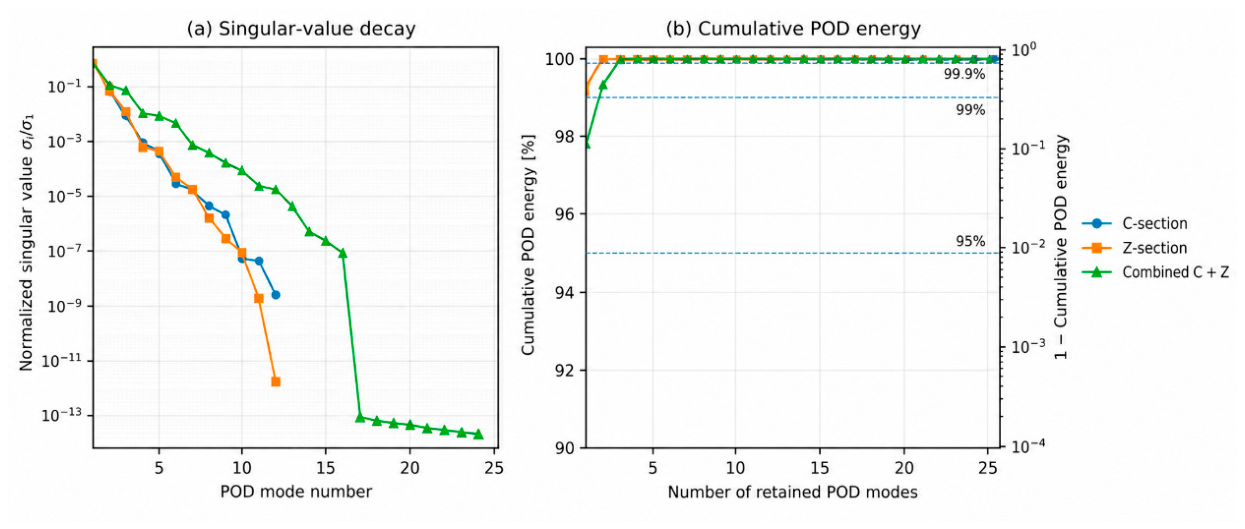
Table 7.
POD compression of the stiffness-correction database.
| Section/data set | Snapshots | Modes for 95% energy | Modes for 99% energy | Modes for 99.9% energy | Adopted | Mean reconstruction error [%] | Maximum reconstruction error [%] |
| C-section | 12 | 1 | 1 | 2 | 2 | 0.881 | 2.010 |
| Z-section | 12 | 1 | 1 | 2 | 2 | 1.293 | 3.015 |
| Combined C + Z | 24 | 1 | 2 | 3 | 3 | 1.465 | 2.944 |
A pronounced singular-value decay was observed. For the C-section database, a single POD mode captured more than 99% of the total energy, while two modes exceeded 99.9%. The same behavior was obtained for the Z-section. When both section types were combined into a single database, one mode still represented more than 95% of the energy, two modes exceeded 99%, and only three modes were required to exceed 99.9%.
Using the adopted 99.9% energy criterion, the mean matrix reconstruction errors were 0.88% for the C-section, 1.29% for the Z-section, and 1.47% for the combined C+Z database. The corresponding maximum errors remained below approximately 3%. The first three modes of the combined database are shown in Figure 12.
The first mode alone contained 97.82% of the total POD energy. The second and third modes contributed only 1.58% and 0.58%, respectively, giving a cumulative energy of 99.9825%. The dominant opening-induced stiffness modification can therefore be interpreted as essentially one-dimensional, while the second and third modes account for comparatively small but mechanically relevant differences between section type and opening geometry.
The representational capability of this low-dimensional basis was additionally verified for an intermediate geometry not included in the POD snapshot grid, with , .
Figure 13.
Comparison between directly condensed and POD-reconstructed stiffness corrections for representative perforated segments: direct result, reconstructed result, and residual matrix.
Figure 13.
Comparison between directly condensed and POD-reconstructed stiffness corrections for representative perforated segments: direct result, reconstructed result, and residual matrix.
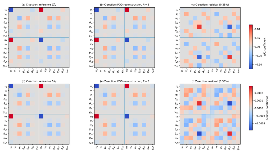
Projection onto only three POD modes reproduced the complete stiffness correction with an error of 0.251% for the C-section and 0.329% for the Z-section. The residual matrices were small compared with the reference corrections and did not reveal any additional dominant stiffness pattern. This confirms that the selected POD basis is sufficiently rich to describe intermediate opening geometries within the analyzed parameter domain.
3.4. Surrogate Prediction of Geometry-Dependent Reduced Stiffness
The dependence of the POD coefficients on the opening dimensions was represented using Gaussian process regression. Separate surrogate models were constructed for the C- and Z-section families, while the same combined three-mode POD basis was retained. The surrogate input consisted of the two dimensionless opening parameters and . Model accuracy was assessed using leave-one-out validation.
Figure 14.
Leave-one-out surrogate predictions of the retained POD coefficients: predicted versus reference values for (a) , (b) , and (c) . C- and Z-section samples are indicated separately; the dashed line represents perfect agreement.
Figure 14.
Leave-one-out surrogate predictions of the retained POD coefficients: predicted versus reference values for (a) , (b) , and (c) . C- and Z-section samples are indicated separately; the dashed line represents perfect agreement.
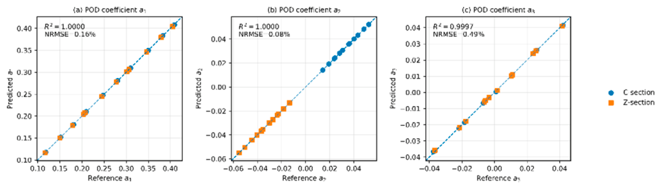
The predicted coefficients showed almost perfect agreement with their reference values. The coefficients of determination were for , , and , respectively. The corresponding normalized RMSE values were 0.157%, 0.081%, and 0.489%.
Table 8a.
Accuracy metrics of the surrogate model for the POD coefficients and the reconstructed reduced stiffness correction.
Table 8a.
Accuracy metrics of the surrogate model for the POD coefficients and the reconstructed reduced stiffness correction.
| Quantity | RMSE | NRMSE [%] | Mean matrix error [%] | Maximum matrix error [%] | |
| 0.00046 | 0.157 | 0.99997 | – | – | |
| 0.00009 | 0.081 | 0.99999 | – | – | |
| 0.00039 | 0.489 | 0.99966 | – | – | |
| Full stiffness correction | – | – | – | 1.486 | 3.036 |
More importantly, the error was also evaluated after reconstruction of the complete stiffness correction rather than only at coefficient level. Across all leave-one-out cases, the mean error of was 1.49%, and the maximum error was 3.04%. For the C-section, the mean and maximum errors were 1.36% and 2.26%, respectively, while for the Z-section they were 1.61% and 3.04%.
Table 8b.
Mean and maximum reconstruction errors of the surrogate-predicted reduced stiffness correction for the C- and Z-sections.
Table 8b.
Mean and maximum reconstruction errors of the surrogate-predicted reduced stiffness correction for the C- and Z-sections.
| Section | Mean matrix error [%] | Maximum matrix error [%] |
| C-section | 1.363 | 2.264 |
| Z-section | 1.610 | 3.036 |
The spatial distribution of the reconstruction error over the investigated parameter domain is shown in Figure 15.
The error remained low throughout the complete range of and . For the C-section, it varied between 0.57% and 2.26%, while for the Z-section it ranged from 0.62% to 3.04%. No localized region of markedly reduced surrogate accuracy was observed. Thus, the combination of POD and Gaussian process regression provides a compact representation of the opening-dependent stiffness matrix over the investigated range of centered rectangular perforations.
3.5. Structural Assembly and Validation Against Full Shell Models
The reduced matrices were finally assembled into complete one-dimensional members and compared directly with detailed shell models. To isolate the error associated with interface reduction and structural assembly, the element matrices used in this subsection were obtained by direct shell condensation and projection rather than from the GPR surrogate. The first validation considered four identical perforated segments modeled as a cantilever and subjected at the free end to kNm and kNm. The total member length was m. Each segment had a length of m and contained a centered rectangular opening with and .
Figure 16.
Validation of the assembled seven-DOF reduced model against the full shell model for a member containing four identical perforated segments under combined bending and torsion: (a) C-section transverse displacement; (b) C-section twist; (c) Z-section transverse displacement; (d) Z-section twist.
Figure 16.
Validation of the assembled seven-DOF reduced model against the full shell model for a member containing four identical perforated segments under combined bending and torsion: (a) C-section transverse displacement; (b) C-section twist; (c) Z-section transverse displacement; (d) Z-section twist.
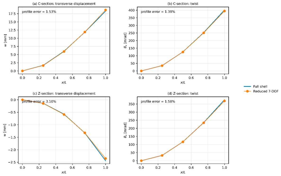
Table 9.
Validation of the assembled reduced model against the complete shell model.
| Quantity | C-section | Z-section |
| Full shell DOFs | 13,932 | 13,932 |
| Reduced DOFs | 35 | 35 |
| Tip displacement, shell [mm] | 18.286 | -2.440 |
| Tip displacement, reduced [mm] | 18.617 | -2.352 |
| Tip displacement error [%] | 1.809 | 3.575 |
| Tip twist, shell [mrad] | 401.260 | 375.842 |
| Tip twist, reduced [mrad] | 394.658 | 368.640 |
| Tip twist error [%] | 1.645 | 1.916 |
| Profile error [%] | 1.531 | 3.103 |
| Profile error [%] | 1.390 | 1.582 |
For the C-section, the profile errors were 1.53% for transverse displacement and 1.39% for twist. The corresponding errors for the Z-section were 3.10% and 1.58%. For the C-section, the shell and reduced tip displacements were 18.286 and 18.617 mm, respectively, while the corresponding twist angles were 401.26 and 394.66 mrad. For the Z-section, the tip displacements were and mm, and the twist angles were 375.84 and 368.64 mrad.
The full shell models contained 13,932 degrees of freedom, whereas the assembled reduced members required only 35 generalized degrees of freedom.
A more demanding validation was performed for a non-uniformly perforated member. Four successive segments were assigned the opening dimensions A consistent orientation of the sectorial warping mode was imposed for all segments before global assembly. The same cantilever boundary conditions and end loads as in the repeated-opening validation case were applied, with kN·m and kN·m at the free end.
Figure 17.
Validation for a non-uniformly perforated member: (a) sequence of normalized opening dimensions and along the four reduced segments; (b) transverse displacement; (c) twist. Full shell and assembled seven-DOF reduced solutions are compared for the C- and Z-sections.
Figure 17.
Validation for a non-uniformly perforated member: (a) sequence of normalized opening dimensions and along the four reduced segments; (b) transverse displacement; (c) twist. Full shell and assembled seven-DOF reduced solutions are compared for the C- and Z-sections.
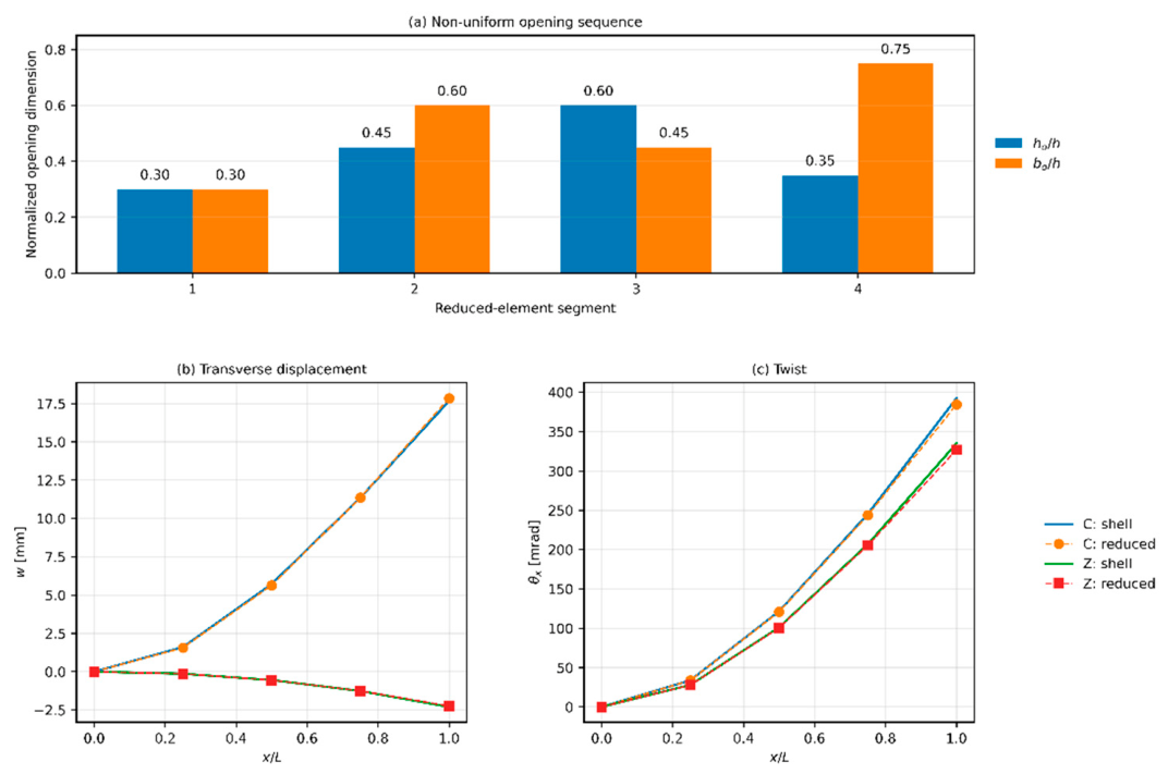
Despite the varying local stiffness matrices, the reduced solution remained in close agreement with the full shell model. For the C-section, the displacement and twist profile errors were 0.93% and 1.71%, respectively. For the Z-section they were 2.30% and 2.08%. The detailed shell model contained 15,912 degrees of freedom, compared with only 35 generalized degrees of freedom in the reduced representation.
For the C-section, the shell and reduced tip displacements were 17.666 and 17.847 mm, respectively, while the corresponding twist angles were 392.50 and 384.50 mrad. For the Z-section, the tip displacements were and mm, with twist angles of 335.12 and 326.77 mrad. The resulting accuracy-to-model-size relation is summarized in Figure 18.
Table 10.
Computational efficiency of the proposed reduced framework.
| Validation case | Reduced formulation | Full shell DOFs | Reduced DOFs | DOF reduction factor | Meanprofileerror [%] | Maximum profile error [%] |
| Repeated perforation, C-section | 7-DOF | 13,932 | 35 | 398.1× | 1.461 | 1.531 |
| Repeated perforation, Z-section | 7-DOF | 13,932 | 35 | 398.1× | 2.343 | 3.103 |
| Non-uniform perforation, C-section | 7-DOF | 15,912 | 35 | 454.6× | 1.318 | 1.705 |
| Non-uniform perforation, Z-section | 7-DOF | 15,912 | 35 | 454.6× | 2.190 | 2.297 |
| Free-warping torsion | 7-DOF | 20,796 | 49 | 424.4× | 1.647 | 1.647 |
| Restrained-warping torsion | 7-DOF | 20,796 | 49 | 424.4× | 0.945 | 0.945 |
| Free-warping torsion | 6-DOF | 20,796 | 42 | 495.1× | 99.873 | 99.873 |
| Restrained-warping torsion | 6-DOF | 20,796 | 42 | 495.1× | 98.608 | 98.608 |
For the repeated-opening members, the reduction in model size was approximately , while for the non-uniform members it reached approximately . The seven-DOF torsional benchmark provided a reduction of approximately . Across all assembled seven-DOF models, the maximum profile error remained below 3.5%.
In contrast, replacing the enriched seven-DOF representation by a six-DOF formulation increased the reduction factor only moderately, from approximately to , while increasing the torsional error to approximately 99%. The additional warping degree of freedom therefore introduces negligible computational overhead but is essential for retaining the mechanics of open thin-walled sections.
Overall, the results demonstrate that the proposed formulation preserves the dominant stiffness, coupling, torsional, and warping characteristics of perforated C- and Z-sections while reducing the dimensionality of the structural model by more than two orders of magnitude. The low-dimensional structure of the opening-induced stiffness correction additionally enables the reduced matrices to be reconstructed efficiently from only a few POD coefficients, providing a practical route from detailed shell analysis to rapid member-level simulation.
4. Discussion
The results demonstrate that the mechanical effect of a web opening in an open thin-walled section cannot be represented adequately by a single stiffness-reduction coefficient. Although the perforation occupies only a local region of the web, its influence propagates through several generalized deformation modes and modifies both diagonal and coupling terms of the reduced stiffness matrix. For the representative opening considered in this study, the Frobenius norm of the dimensionless stiffness correction reached approximately 28% of the corresponding unperforated matrix for both C- and Z-sections. More importantly, the correction was highly non-uniform. This observation provides the principal motivation for representing the perforated segment through the complete reduced matrix rather than through independently modified classical section properties.
Among the individual deformation mechanisms, transverse shear was consistently the most sensitive to the presence of an opening. Increasing the opening height to reduced the corresponding normalized stiffness measure to approximately 0.24, whereas the bending-related stiffness remained close to 0.96. A similar tendency was observed when the longitudinal dimension of the opening was increased. At , the shear-related stiffness decreased to approximately one third of the unperforated value, while the bending-related measure remained above 0.98. This distinction is mechanically reasonable because the opening directly interrupts the web region responsible for transmitting shear, whereas global bending stiffness remains dominated by the flange system and by material located farther from the neutral axis.
The torsional and warping responses revealed a more complex dependence on cross-section type. While the shear-related measures for C- and Z-sections were almost identical for the investigated centered openings, their torsional and warping contributions evolved differently. For the largest opening height considered, the torsional measure of the C-section decreased substantially, whereas the corresponding Z-section value remained close to that of the solid section. The reverse tendency was observed for the warping-related stiffness. This indicates that torsion and sectorial warping should not be treated as independent scalar corrections. Their interaction depends on cross-sectional geometry and on the distribution of the opening-induced perturbation relative to the open-section warping field.
A particularly important result concerns the selection of interface degrees of freedom. Retaining only the three translational shell degrees of freedom at each interface node before projection produced a more accurate reduced description than retaining all six shell degrees of freedom. When shell rotations were directly retained and subsequently linked to the generalized beam kinematics, the torsional response became artificially stiff. In the present formulation, the shell rotations therefore remain internal variables and are eliminated through static condensation. This is not merely a numerical convenience. It avoids imposing an unnecessarily restrictive rotational field on the shell interface and allows the condensed shell solution to develop the local bending and rotational patterns required by the thin-walled cross-section.
The second essential ingredient is the explicit sectorial warping degree of freedom. The comparison between the six- and seven-DOF formulations showed that the six-DOF rigid-section interface projection adopted in the present reduction is insufficient to reproduce the torsional response of the considered open thin-walled members. Under both free- and restrained-warping torsion, omission of the warping coordinate resulted in errors approaching 99%. The seven-DOF formulation reduced these errors to approximately 1–2%. The very large discrepancy of the six-DOF model arises because successive reduced interfaces effectively suppress the axial warping deformation that develops naturally in an open section. Thus, the additional generalized coordinate should not be regarded as a refinement needed only for specialized torsional cases. It is required to preserve the underlying kinematics of the shell model during one-dimensional assembly.
The present approach differs from existing advanced one-dimensional descriptions in the manner in which perforation effects are introduced. GBT-based formulations [22,23,24,25,26,27,28,29,30] enrich the beam kinematics analytically to represent local and distortional deformation associated with openings, whereas the present method transfers these local effects directly from a detailed shell segment through static condensation and energetic projection. Compared with the earlier shell-to-beam homogenization approach [32], the current formulation retains an explicit sectorial warping coordinate and the complete coupled reduced stiffness operator rather than a set of independently identified equivalent sectional stiffnesses. It also differs from homogenized equivalent-property models such as [37], because the opening effect is represented as a matrix-valued correction, preserving interactions between bending, shear, torsion, and warping.
At the same time, the opening-induced stiffness correction was found to possess a remarkably low-dimensional structure. For the separate C- and Z-section databases, two POD modes were sufficient to exceed 99.9% of the snapshot energy. Even when both section families were combined, only three modes were required. The first mode alone represented approximately 97.8% of the total snapshot energy. This means that, although formally contains many independent matrix entries, the physically admissible changes induced by the investigated openings occupy only a small subspace of that matrix space. In mechanical terms, the opening modifies several stiffness and coupling terms simultaneously, but these modifications are strongly correlated rather than independent.
The POD reconstruction of an intermediate geometry not contained in the snapshot grid further supports this interpretation. Using only three modes, the full stiffness correction was recovered with errors of approximately 0.25% and 0.33% for the C- and Z-sections, respectively. Consequently, the reduced basis does not merely compress the original snapshots; it also provides an effective representation of intermediate geometries within the considered parameter domain.
This property makes surrogate modeling particularly attractive. Instead of predicting every independent component of a symmetric stiffness matrix, the surrogate needs to predict only three scalar POD coefficients. The leave-one-out Gaussian-process results showed coefficients of determination above 0.9996 for all three amplitudes. After reconstruction of the complete matrix, the mean error remained approximately 1.5%, with a maximum of about 3.0%. The error maps also showed no isolated region of pronounced deterioration within the sampled domain. The combination of physically based dimensionality reduction and a lightweight regression model therefore appears preferable to direct black-box prediction of the stiffness matrix.
The assembled-member simulations provide the most direct verification of the proposed framework. For members composed of repeated identical perforated segments, reduction from approximately 14,000 shell degrees of freedom to only 35 generalized degrees of freedom resulted in displacement and twist errors generally between 1% and 3%. Similar accuracy was maintained for non-uniform members assembled from segments with different opening dimensions. In the latter case, the reduction factor exceeded 450 while the maximum profile error remained approximately 2.3%. These results are particularly significant because no additional calibration was introduced at member level; each global model was assembled directly from independently reduced segment matrices.
For non-uniform assembly, one implementation detail deserves attention. The sectorial warping function is defined only up to a multiplicative sign. Independently generated reduced segments may therefore contain equivalent warping modes with opposite orientation. A common sign convention must be enforced before adjacent matrices are assembled. Once this orientation was made consistent, the non-uniform C- and Z-section models reproduced the shell solutions with the expected accuracy. This requirement is straightforward computationally but important for any automated library of reduced perforated elements.
The reduction factors reported here refer to the number of structural degrees of freedom rather than directly to CPU-time acceleration. Actual computational speed-up depends on the solver, matrix sparsity, preprocessing, and the number of repeated analyses. Nevertheless, reducing a shell model containing approximately – degrees of freedom to several tens of generalized unknowns fundamentally changes the computational scale of member-level simulation. The advantage becomes particularly relevant in optimization, uncertainty propagation, inverse identification, or digital-model applications, where the same structural system may need to be evaluated thousands of times.
Several limitations should also be acknowledged. The present formulation is restricted to linear elastic response and therefore does not describe local yielding, plastic redistribution, local or distortional buckling, or post-buckling behavior around the opening. The numerical database used for POD and surrogate validation is intentionally compact and focuses primarily on centered rectangular openings. The current treatment of curved opening boundaries also relies on the available shell discretization strategy and should be replaced by a fully conforming representation before quantitative conclusions are drawn regarding corner-radius effects or detailed comparisons between circular, elliptical, and rounded-rectangular holes. Likewise, extension to additional section dimensions, thickness ratios, opening eccentricities, lip geometries, and material parameters would require enlargement of the parameter space and reassessment of the POD basis.
These limitations do not affect the central observation of the study: local shell mechanics around a perforation can be retained in a compact generalized stiffness matrix and subsequently propagated through a one-dimensional structural model. The framework therefore occupies an intermediate level between conventional beam models, which may lose important local coupling and warping effects, and full shell simulations, which retain these effects at considerably greater computational cost.
5. Conclusions
A reduced stiffness formulation for perforated thin-walled C- and Z-sections was developed by combining shell finite element analysis, static condensation, enriched beam-type interface kinematics, proper orthogonal decomposition, and surrogate modeling. The study leads to several main conclusions.
The most accurate interface representation was obtained by retaining only translational shell degrees of freedom during static condensation and eliminating shell nodal rotations as internal variables. Projection onto seven generalized degrees of freedom per reduced node, including an explicit sectorial warping coordinate, was essential. Removing this coordinate produced torsional errors close to 99%, whereas the enriched formulation reproduced the shell torsional response with errors of approximately 1–2%.
Web openings affected the generalized stiffness matrix in a strongly non-uniform manner. For a representative perforation, the magnitude of the total stiffness correction was approximately 28% of the unperforated matrix. Transverse shear was the most strongly affected deformation mechanism, while bending stiffness was considerably less sensitive. Torsional and warping contributions depended more strongly on whether the member had a C- or Z-shaped cross-section.
The opening-induced correction was also highly compressible. Two POD modes represented more than 99.9% of the snapshot energy for the individual C- and Z-section databases, and three modes were sufficient for the combined database. For an intermediate geometry not included in the snapshot set, the three-mode reconstruction error remained below 0.35%.
Gaussian-process surrogates accurately reproduced the three POD coefficients. Leave-one-out validation gave for all coefficients, while the reconstructed complete stiffness correction had a mean error of approximately 1.5% and a maximum error of approximately 3%.
At member level, the proposed formulation reduced shell models containing approximately 14,000–16,000 degrees of freedom to only 35 generalized degrees of freedom. This corresponds to reductions of approximately –, while global displacement and twist profile errors remained below approximately 3.2% for all assembled seven-DOF validation cases, including members with non-uniform opening geometries.
Overall, the proposed approach provides a compact bridge between detailed shell mechanics and efficient one-dimensional analysis. It retains opening-induced stiffness coupling and sectorial warping while enabling the reduced matrices to be represented by only a few geometry-dependent coefficients. This makes the formulation particularly suitable for rapid parametric analysis, optimization, probabilistic simulation, and future digital-model applications involving long perforated thin-walled members.
Author Contributions
Conceptualization, T.G. and J.P.; methodology, T.G.; software, T.G.; validation, J.P., Z.P. and T.G.; formal analysis, J.P.; investigation, J.P.; resources, Z.P.; data curation, Z.P.; writing—original draft preparation, T.G. and J.P.; writing—review and editing, Z.P. and T.G.; visualization, T.G. and J.P.; supervision, T.G.; project administration, J.P.; funding acquisition, Z.P. and J.P. All authors have read and agreed to the published version of the manuscript.
Funding
This research was funded by The National Centre for Research and Development, grant number POIR.01.01.01-00-0177/21.
Institutional Review Board Statement
Not applicable.
Informed Consent Statement
Not applicable.
Data Availability Statement
The data presented in this study is available on request from the corresponding author.
Acknowledgments
This work was published within the grant of The National Centre for Research and Development under the number POIR.01.01.01-00-0177/21.
Conflicts of Interest
The authors declare no conflicts of interest.
References
- Miller, T.H.; Peköz, T. Unstiffened strip approach for perforated wall studs. J. Struct. Eng. 1994, 120, 410–421. [Google Scholar] [CrossRef]
- Shan, M.Y.; LaBoube, R.A.; Yu, W.W. Bending and shear behavior of web elements with openings. J. Struct. Eng. 1996, 122, 854–859. [Google Scholar] [CrossRef]
- LaBoube, R.A.; Yu, W.W.; Langan, J.E.; Shan, M.Y. Cold-formed steel webs with openings: Summary report. Thin-Walled Struct. 1997, 27, 79–84. [Google Scholar] [CrossRef]
- Davies, J.M.; Leach, P.; Taylor, A. The design of perforated cold-formed steel sections subject to axial load and bending. Thin-Walled Struct. 1997, 29, 141–157. [Google Scholar] [CrossRef]
- Salhab, B.; Wang, Y.C. Equivalent thickness of cold-formed thin-walled channel sections with perforated webs under compression. Thin-Walled Struct. 2008, 46, 823–838. [Google Scholar] [CrossRef]
- Moen, C.D.; Schafer, B.W. Elastic buckling of thin plates with holes in compression or bending. Thin-Walled Struct. 2009, 47, 1597–1607. [Google Scholar] [CrossRef]
- Moen, C.D.; Schafer, B.W. Direct Strength Method for design of cold-formed steel columns with holes. J. Struct. Eng. 2011, 137, 559–570. [Google Scholar] [CrossRef]
- Uzzaman, A.; Lim, J.B.P.; Nash, D.; Rhodes, J.; Young, B. Cold-formed steel sections with web openings subjected to web crippling under two-flange loading conditions—Part I: Tests and finite element analysis. Thin-Walled Struct. 2012, 56, 38–48. [Google Scholar] [CrossRef]
- Uzzaman, A.; Lim, J.B.P.; Nash, D.; Rhodes, J.; Young, B. Cold-formed steel sections with web openings subjected to web crippling under two-flange loading conditions—Part II: Parametric study and proposed design equations. Thin-Walled Struct. 2012, 56, 79–87. [Google Scholar] [CrossRef]
- Casafont, M.; Pastor, M.; Bonada, J.; Roure, F.; Peköz, T. Linear buckling analysis of perforated steel storage rack columns with the Finite Strip Method. Thin-Walled Struct. 2012, 61, 71–85. [Google Scholar] [CrossRef]
- Smith, F.H.; Moen, C.D. Finite strip elastic buckling solutions for thin-walled metal columns with perforation patterns. Thin-Walled Struct. 2014, 79, 187–201. [Google Scholar] [CrossRef]
- Cai, J.; Moen, C.D. Elastic buckling analysis of thin-walled structural members with rectangular holes using generalized beam theory. Thin-Walled Struct. 2016, 107, 274–286. [Google Scholar] [CrossRef]
- Wang, L.; Young, B. Design of cold-formed steel built-up sections with web perforations subjected to bending. Thin-Walled Struct. 2017, 120, 458–469. [Google Scholar] [CrossRef]
- Yuan, W.-B.; Yu, N.-T.; Li, L.-Y. Distortional buckling of perforated cold-formed steel channel-section beams with circular holes in web. Int. J. Mech. Sci. 2017, 126, 255–260. [Google Scholar] [CrossRef]
- Chen, B.; Roy, K.; Uzzaman, A.; Raftery, G.M.; Nash, D.; Clifton, G.C.; Pouladi, P.; Lim, J.B.P. Effects of edge-stiffened web openings on the behaviour of cold-formed steel channel sections under compression. Thin-Walled Struct. 2019, 144, 106307. [Google Scholar] [CrossRef]
- Pham, S.H.; Pham, C.H.; Rogers, C.A.; Hancock, G.J. Shear strength experiments and design of cold-formed steel channels with web holes. J. Struct. Eng. 2020, 146, 04019173. [Google Scholar] [CrossRef]
- Yu, N.-T.; Kim, B.; Li, L.-Y.; Hong, W.-J.; Yuan, W.-B. Distortional buckling of perforated cold-formed steel beams subject to uniformly distributed transverse loads. Thin-Walled Struct. 2020, 148, 106569. [Google Scholar] [CrossRef]
- Qin, J.; Guo, X.; Liao, L.; Li, G. Analytical method for distortional buckling load of cold-formed steel members with perforated web under bending moment. Structures 2023, 57, 105189. [Google Scholar] [CrossRef]
- Ma, R.; Fang, Z.; Xi, X.; Tiwari, S.; Roy, K.; Lim, J.B.P. Structural behaviour of cold-formed steel channels with unstiffened and edge-stiffened web holes under combined compression and bending. Structures 2025, 82, 110509. [Google Scholar] [CrossRef]
- Shabhari, A.; Jeyapragasam, V.V.K.; Chandrasekar, D. Distortional buckling behaviour of web perforated cold-formed steel lipped channel columns. J. Constr. Steel Res. 2026, 237, 110128. [Google Scholar] [CrossRef]
- Zeng, J.; Xu, N.; He, J.; Liu, W.; Zhang, L.; Cai, Y. Recent developments in the mechanical properties of perforated cold-formed thin-walled steel members. Mech. Solids 2025, 60, 4786–4800. [Google Scholar] [CrossRef]
- Gonçalves, R.; Dinis, P.B.; Camotim, D. GBT formulation to analyse the first-order and buckling behaviour of thin-walled members with arbitrary cross-sections. Thin-Walled Struct. 2009, 47, 583–600. [Google Scholar] [CrossRef]
- Gonçalves, R.; Camotim, D.; Basaglia, C.; Martins, A.D.; Peres, N. Latest developments on the analysis of thin-walled structures using Generalised Beam Theory (GBT). J. Constr. Steel Res. 2023, 204, 107858. [Google Scholar] [CrossRef]
- Bonada, J.; Casafont, M.; Roure, F.; Pastor, M.M. Geometrically nonlinear analysis of perforated rack columns under a compression load by means of Generalized Beam Theory. Thin-Walled Struct. 2021, 166, 108102. [Google Scholar] [CrossRef]
- Duan, L.; Zhao, J. An extended first-order generalized beam theory for perforated thin-walled members. Thin-Walled Struct. 2021, 161, 107492. [Google Scholar] [CrossRef]
- Duan, L.; Zhao, J.; Zou, J. Generalized beam theory-based advanced beam finite elements for linear buckling analyses of perforated thin-walled members. Comput. Struct. 2022, 259, 106683. [Google Scholar] [CrossRef]
- Duan, L.; Zhao, J. An extended GBT formulation for elastoplastic analyses of perforated thin-walled members. Thin-Walled Struct. 2022, 181, 110143. [Google Scholar] [CrossRef]
- Duan, L.; Miao, J.; Li, H.-T.; Zhao, J. Extended GBT formulation for eigenvalue buckling analyses of thin-walled members with edge-stiffened holes. Thin-Walled Struct. 2024, 197, 111628. [Google Scholar] [CrossRef]
- Duan, L.; Miao, J.; Zhao, J. An extended Generalized Beam Theory formulation for large deformation analyses of perforated thin-walled members. Comput. Struct. 2026, 321, 108052. [Google Scholar] [CrossRef]
- López-Rull, I.; Bonada, J.; Bové, O.; Casafont, M. Dynamic analysis with point-masses of perforated pallet rack structural members by means of the Generalized Beam Theory. Thin-Walled Struct. 2024, 202, 112090. [Google Scholar] [CrossRef]
- Guyan, R.J. Reduction of stiffness and mass matrices. AIAA J. 1965, 3, 380. [Google Scholar] [CrossRef] [PubMed]
- Staszak, N.; Gajewski, T.; Garbowski, T. Shell-to-beam numerical homogenization of 3D thin-walled perforated beams. Materials 2022, 15, 1827. [Google Scholar] [CrossRef] [PubMed]
- Gajewski, T.; Staszak, N.; Garbowski, T. Parametric optimization of thin-walled 3D beams with perforation based on homogenization and soft computing. Materials 2022, 15, 2520. [Google Scholar] [CrossRef] [PubMed]
- Staszak, N.; Gajewski, T.; Garbowski, T. Effective stiffness of thin-walled beams with local imperfections. Materials 2022, 15, 7665. [Google Scholar] [CrossRef] [PubMed]
- Garbowski, T.; Knitter-Piątkowska, A.; Mrówczyński, D. Numerical homogenization of multi-layered corrugated cardboard with creasing or perforation. Materials 2021, 14, 3786. [Google Scholar] [CrossRef] [PubMed]
- Garbowski, T.; Gajewski, T. Determination of transverse shear stiffness of sandwich panels with a corrugated core by numerical homogenization. Materials 2021, 14, 1976. [Google Scholar] [CrossRef] [PubMed]
- Dong, Z.-C.; Xu, M.-H.; Shen, B.; Xie, Q.-Q.; Cao, T.-T.; Ma, K.-J. Homogenised model of a common perforated steel beam with four types of openings under uniformly distributed lateral loading. Thin-Walled Struct. 2023, 192, 111107. [Google Scholar] [CrossRef]
- Eftekhar Azam, S.; Mariani, S. Investigation of computational and accuracy issues in POD-based reduced order modeling of dynamic structural systems. Eng. Struct. 2013, 54, 150–167. [Google Scholar] [CrossRef]
- Ritzert, S.; Macek, D.; Simon, J.-W.; Reese, S. Reduced order modeling of modular parameter dependent structures based on proper orthogonal decomposition and mesh tying. Proc. Appl. Math. Mech. 2023, 22, e202200189. [Google Scholar] [CrossRef]
Figure 1.
Geometry of the perforated C- and Z-section segments, local coordinate system, intact end interfaces and , and parameters describing the web opening.
Figure 1.
Geometry of the perforated C- and Z-section segments, local coordinate system, intact end interfaces and , and parameters describing the web opening.
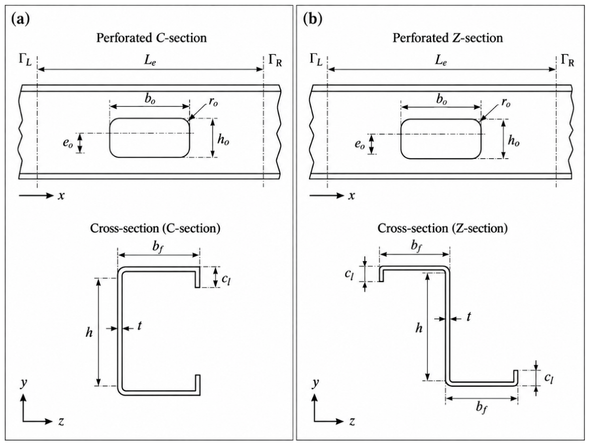
Figure 2.
Static-condensation stage of the shell-to-reduced-element formulation: full shell segment, partition into retained interface translations and eliminated degrees of freedom, static condensation, and the condensed interface relation .
Figure 2.
Static-condensation stage of the shell-to-reduced-element formulation: full shell segment, partition into retained interface translations and eliminated degrees of freedom, static condensation, and the condensed interface relation .

Figure 3.
Shell-to-reduced-element workflow. Route A uses explicit static condensation to obtain followed by projection onto the enriched interface basis. Route B identifies the same from fourteen unit generalized-displacement analyses and projected interface reactions.
Figure 3.
Shell-to-reduced-element workflow. Route A uses explicit static condensation to obtain followed by projection onto the enriched interface basis. Route B identifies the same from fourteen unit generalized-displacement analyses and projected interface reactions.
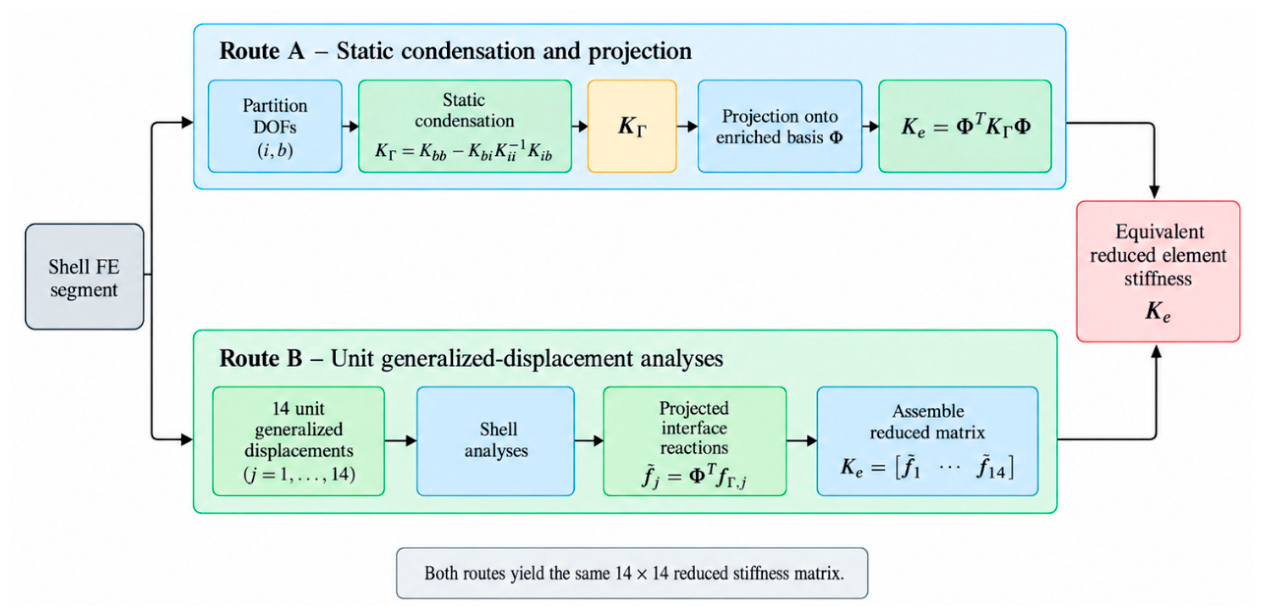
Figure 5.
Assembly of a perforated member from reduced elements. Each intact interface carries seven generalized degrees of freedom; the sectorial warping amplitude is shared between adjacent elements in the same manner as the classical translations and rotations.
Figure 5.
Assembly of a perforated member from reduced elements. Each intact interface carries seven generalized degrees of freedom; the sectorial warping amplitude is shared between adjacent elements in the same manner as the classical translations and rotations.
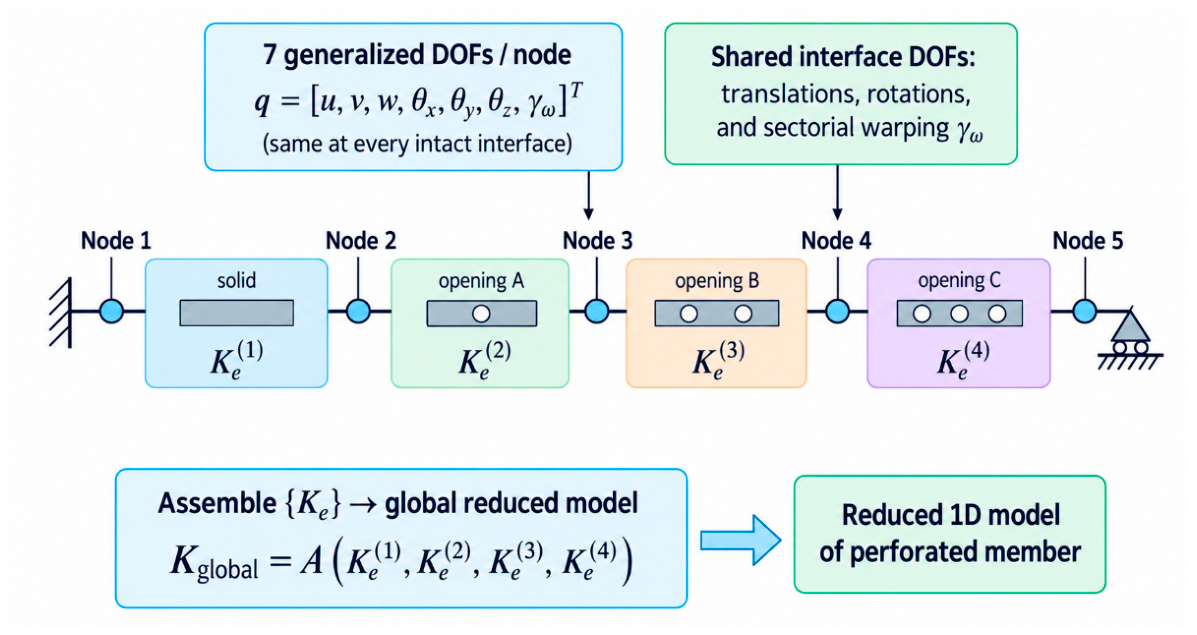
Figure 8.
Dimensionless reduced stiffness matrices and opening-induced corrections: (a) for the C-section; (b) for a representative perforated C-section; (c) for the Z-section; (d) for the corresponding perforated Z-section.
Figure 8.
Dimensionless reduced stiffness matrices and opening-induced corrections: (a) for the C-section; (b) for a representative perforated C-section; (c) for the Z-section; (d) for the corresponding perforated Z-section.
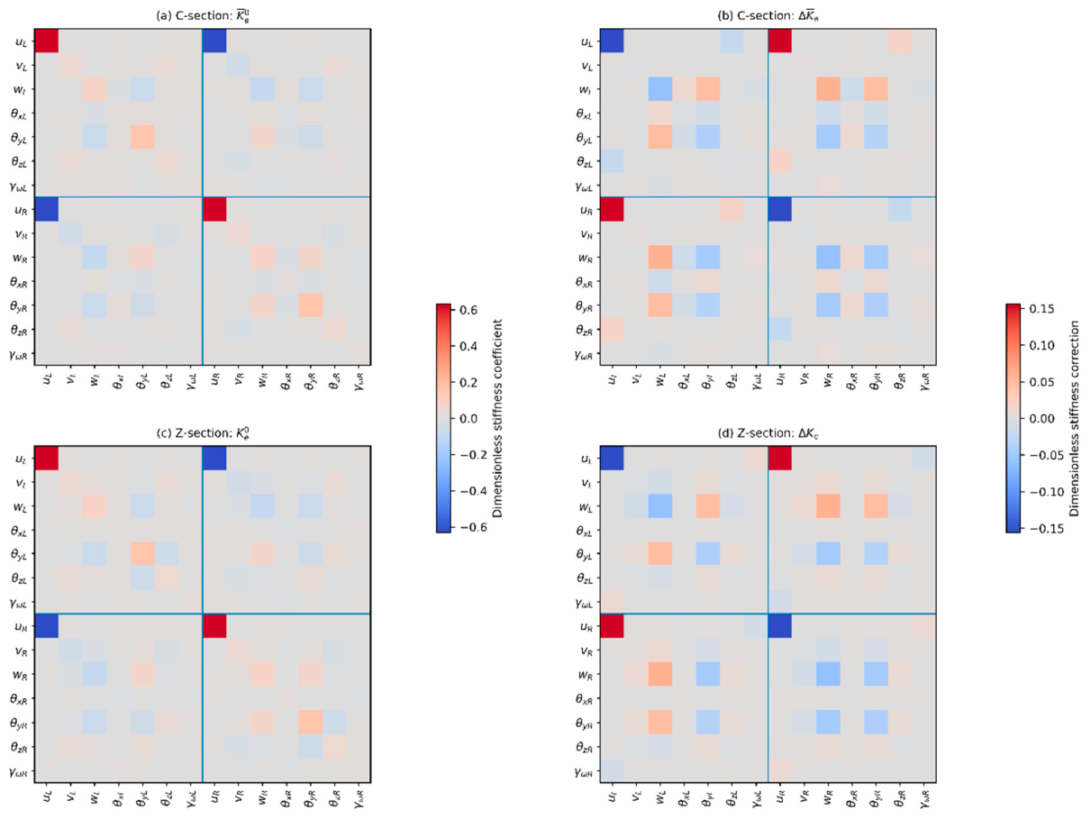
Figure 12.
Leading POD modes of the dimensionless stiffness-correction matrix for the combined C+Z database: (a) ; (b) ; (c) .
Figure 12.
Leading POD modes of the dimensionless stiffness-correction matrix for the combined C+Z database: (a) ; (b) ; (c) .
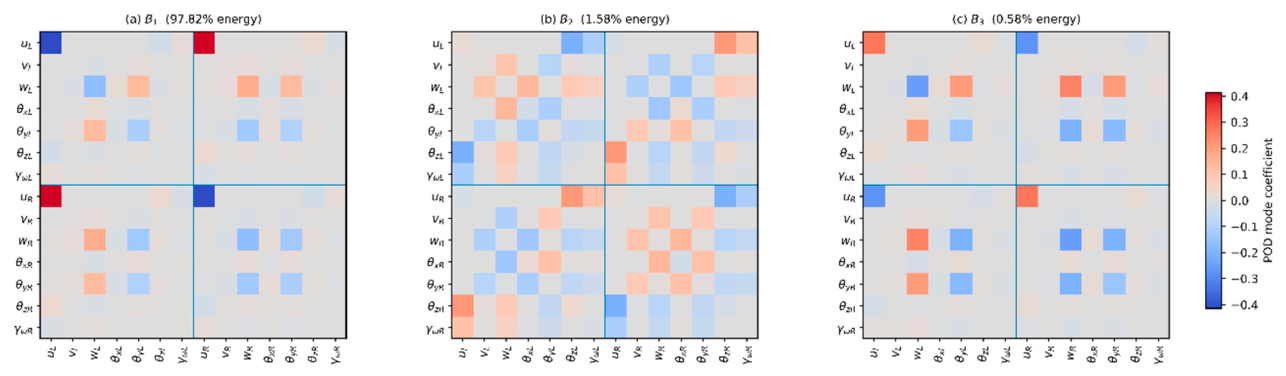
Figure 15.
Leave-one-out relative reconstruction error of the complete dimensionless stiffness correction over the investigated parameter domain : (a) C-section; (b) Z-section.
Figure 15.
Leave-one-out relative reconstruction error of the complete dimensionless stiffness correction over the investigated parameter domain : (a) C-section; (b) Z-section.
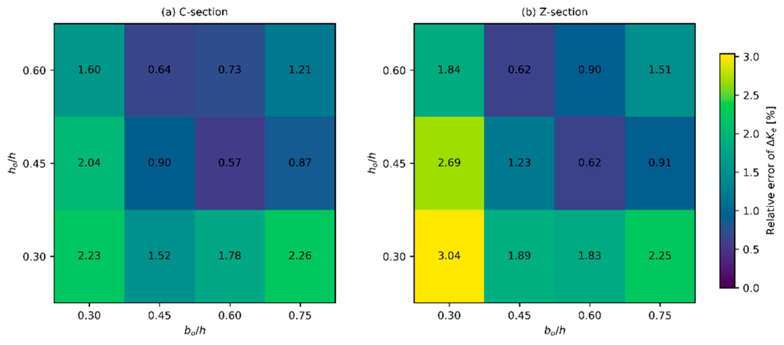
Figure 18.
Accuracy–efficiency comparison of the investigated modeling strategies.
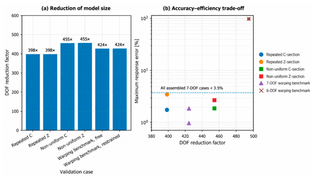
Table 1.
Geometric and material quantities used in the reduced-stiffness formulation.
| Symbol | Definition | Dimensionless form / comment |
| clear web height | characteristic length | |
| flange width | ||
| lip length, when present | ||
| wall thickness | ||
| reduced-element length | ||
| opening height | ||
| opening length in the longitudinal direction | ||
| vertical eccentricity of the opening center | ||
| corner radius, when applicable | ||
| Young’s modulus | linear elastic material parameters |
|
| Poisson’s ratio |
Table 2.
Reduced interface bases considered for assessment of the warping enrichment.
| Model | Generalized coordinates at each end | Element matrix size | Purpose |
| B6 | classical rigid-section reference | ||
| B7 | proposed warping-enriched model |
Table 3.
Validation hierarchy and representative load cases.
| Level | Compared models | Representative actions | Main quantities assessed |
| 1 | B6, B7, detailed shell | axial force, major/minor bending, shear, torsion, combined bending-torsion | displacement, twist, strain energy, influence of warping enrichment |
| 2 | surrogate-predicted , directly condensed | geometries excluded successively in leave-one-out validation | coefficient error, matrix error, positive-definiteness check |
| 3 | assembled reduced member, full shell member | bending, torsion with free warping, torsion with restrained warping, combined loading | deflection and twist distributions, generalized section response |
Table 6.
Magnitude of the opening-induced stiffness correction for the representative centered rectangular opening.
Table 6.
Magnitude of the opening-induced stiffness correction for the representative centered rectangular opening.
| Section | Opening shape | Relative correction [%] | |||
| C-section | Rectangular | 0.600 | 0.533 | 0 | 28.451 |
| Z-section | Rectangular | 0.600 | 0.533 | 0 | 28.064 |
Disclaimer/Publisher’s Note: The statements, opinions and data contained in all publications are solely those of the individual author(s) and contributor(s) and not of MDPI and/or the editor(s). MDPI and/or the editor(s) disclaim responsibility for any injury to people or property resulting from any ideas, methods, instructions or products referred to in the content. |
© 2026 by the authors. Licensee MDPI, Basel, Switzerland. This article is an open access article distributed under the terms and conditions of the Creative Commons Attribution (CC BY) license (http://creativecommons.org/licenses/by/4.0/).
Copyright: This open access article is published under a Creative Commons CC BY 4.0 license, which permit the free download, distribution, and reuse, provided that the author and preprint are cited in any reuse.