

Submitted:
08 September 2026
Posted:
09 September 2026
You are already at the latest version
Abstract
To address the drawbacks of horizontal- and vertical-axis wind turbines, a new concept has recently emerged. A novel active-axis wind turbine (AAWT) aims to reduce mechanical loads and structural costs when compared to conventional horizontal-axis wind turbines. The AAWT uses a pitch-tilt angle mechanism to balance aerodynamic lift and centrifugal forces acting on the rotor, thereby providing stable rotor rotation. Previous research on a small laboratory prototype AAWT established the relationship between pitch and tilt angles for quasi-static equilibrium. However, the transient dynamic behaviour about the tilt axis during movement between these states has not yet been investigated. This work develops a transient dynamic model of the AAWT pitch-tilt mechanism and controls the transition between the equilibrium states of aerodynamic lift and centrifugal moments. The cross-arm tilt axis is introduced as the first degree of freedom of the rotation system, triggered by a change in balance between the aerodynamic lift moment and the centrifugal moment about the tilt axis. A controller that combines feedforward and PD feedback is used to control the tilt transition and compensate for the lack of a mechanical damper on the tilt arm axis. To achieve a stable response across different rotor speeds, gain scheduling is applied to the controller’s derivative term. The results show that the PD controller can suppress oscillations in the transient response and provide smooth convergence to the new target equilibrium point. At different tested rotor rotation speeds, the settling time decreases with increasing rotation speed. The research provides a basis for future control-strategy experiments to achieve dynamic changes in tilt angle in the AAWT.
Keywords:
wind turbine
; pitch and tilt angle control
; virtual damper
; PD controller
; settling time
1. Introduction
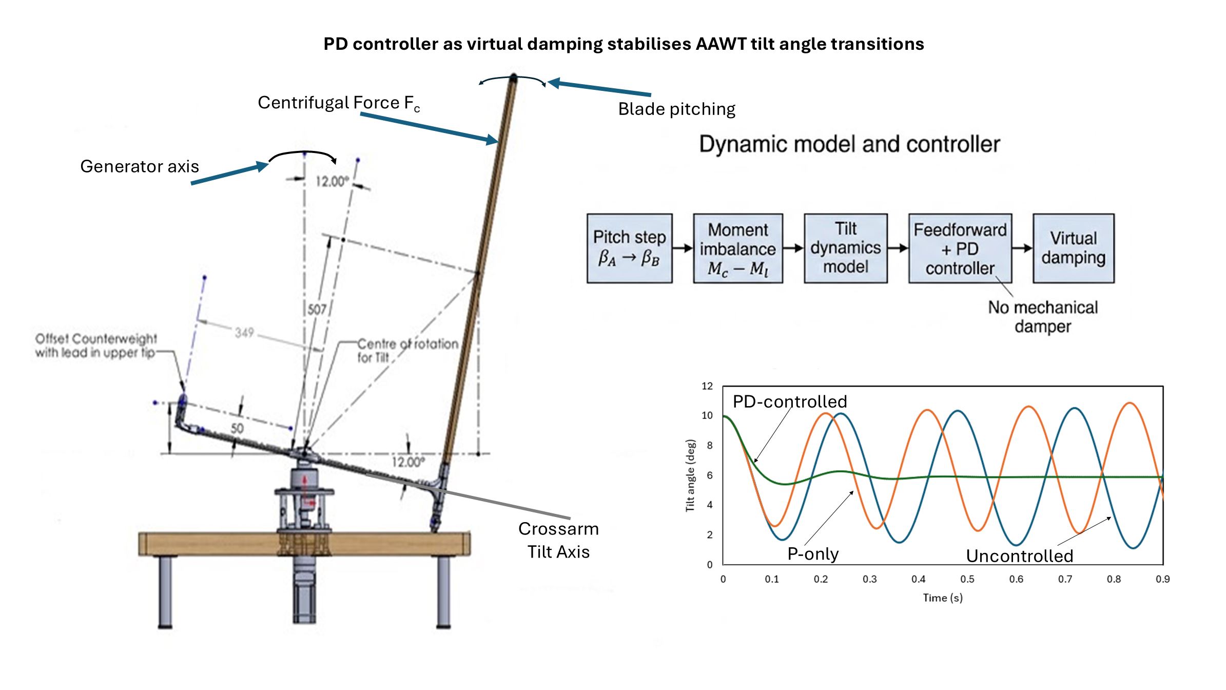
Wind energy systems continue to develop and mature in technology, toward lighter, more reliable, and more efficient structural engineering [1,2]. As energy demands grow, larger turbines are required to optimise power generation and reduce the Levelized Cost of Energy (LCoE) [3,4]. With larger turbines, there are challenges in tower design regarding loads and costs [1,3]. It is desirable to continue the progress of wind energy technology toward even lower costs. Also [5] states that as modern wind turbines continue to grow in size and capacity, advanced control strategies are required to ensure optimal power capture, structural load mitigation and system reliability. The active-axis wind turbine (AAWT) is an emerging innovation designed to reduce blade, tower and foundation loads and their attendant cost. Unlike conventional wind turbines, the AAWT employs a pitch-and-tilt control mechanism that actuates the turbine rotor blade, dynamically changing its orientation using a pitch control system (see Figure 1). By achieving the correct pitch-tilt relationship, the system allows balancing between aerodynamic lift and centrifugal forces, thereby sustaining stability and reducing the need for heavy blade and tower support structures. Given that wind turbine towers can account for 20%-30% of the cost of a wind turbine project, reducing the need for these structures and their foundations, and further reducing blade costs, would significantly improve the LCOE [6] for wind.
The principal concept of the Active Axis Wind Turbine (AAWT) is illustrated in Figure 1. In this concept, the AAWT does not have tower, unlike HAWTs, which are supported by a conventional tower. Instead, the blade is intended to follow a controlled pitched and tilted flight path around the generator axis. The blade pitch angle is actively regulated about the blade’s longitudinal axis to generate aerodynamic lift. This elevates the blade and determines the tilt angle. The central design philosophy is to balance the aerodynamic lift moment with the centrifugal moment so that the blade can maintain a stable operating path.
The current study does not model a full-scale commercial AAWT. Instead, it develops a control-oriented dynamic tilt model based on the small laboratory proof-of-concept prototype previously developed and published by Mezaal et al.[7]. The prototype was designed and built to demonstrate the feasibility of the pitch-tilt mechanism and to establish the equilibrium pitch–tilt relationship. This paper extends that work by investigating the transient tilt response when the system moves between equilibrium operating points.
Recent research by Mezaal et al. [7] identified the specific combinations of pitch and tilt angles required for the AAWT to maintain equilibrium between aerodynamic and centrifugal forces in the absence of wind. The study calculated the mass distribution of each rotor component required for the rotating rotor to produce lift and centrifugal forces that are in equilibrium. This quasi-static relationship achieves a condition in which the net torque acting on the rotor about the tilt axis approaches zero. Although the study [7] established the equilibrium combinations of pitch and tilt, the dynamic transient behaviour of the tilt during movement between equilibrium points is less well understood.
. If the AAWT is operated in a steady wind, with constant pitch and a circular blade tip path, then the aerodynamic and centrifugal forces would be in the same direction during the downwind pass of the blade. This is not a desired situation, as it would require infrastructure (e.g., horizontal stays) to ensure the rotor remains intact. The role of the control system is to pitch the blade as the rotor rotates [8] so that the tip of the blade traverses a path where the forces are in balance. A step change in the pitch angle can be a useful mathematical construct to examine the transition from one equilibrium operating point to another. During the transition period, an imbalance between aerodynamic and centrifugal moments can generate oscillations in the tilt angle response, as there is no physical damper to suppress it. Consequently, understanding the system’s behaviour and controlling oscillations during the transition are crucial to ensuring stable, reliable operation.
Having an accurate model of aerodynamic forces is important. The model for the aerodynamic and centrifugal forces acting on the rotor of AAWT is developed in [7]. The rotor blade design uses an NACA0018 airfoil, and experimental data from Jacobs et al. [6] were used to estimate the lift coefficient for the AAWT simulation model. The velocities and dimensions involved in the AAWT rotor design result in a low Reynolds number model. Timmer et al. [9] conducted wind-tunnel tests on the NACA0018 airfoil, producing aerodynamic data at low Reynolds numbers used for this study. A 4th-order polynomial is used to plot the trend in lift coefficient with angle of attack (a).
1.1. Literature Review and Research Gap
Reduced-order simulation models are commonly employed in wind turbine control design, fast simulation, or dynamic operation analysis to achieve near-high aeroelastic fidelity while significantly reducing computational cost [10,11,12]. Research on floating large-scale wind turbines showed that a simplified dynamic model for a nonlinear system can maintain the required control-relevant states while eliminating computationally burdensome full-physics models [13,14]. The model reduction strategy is significant when the aim is to study and analyse the system’s transient response, state transitions under operating change conditions, and the controller’s contribution. A recent study on wind turbine control and load reduction emphasises the need for models that retain crucial nonlinearity rather than linearising [15].
Control strategies were used in recent wind turbine control literature to provide damping compensation when an inherent physical damper is limited or absent [16,17,18]. This method was specifically used for floating offshore wind turbines, as the floating platform’s surge and pitch, and the rotor dynamics, strongly interact. Also, a lack of structural damping can cause oscillatory behaviour problems. Capaldo and Mella [16] demonstrated that a control strategy can be designed to add explicit damping to platform pitch motion. This damping can thereby reduce vibration and preserve the platform’s natural pitch movement. Moreover, a review study on vibration and load alleviation [8] showed that active control in wind turbines is not only used to regulate power but also to shape the dynamic response and reduce oscillations. In the absence of a physical damper, the controller can contribute to stabilising and suppressing oscillations by operating at transition points [16,18,19,20].
In wind turbine systems with nonlinear behaviour, feedback with a conventional feedback controller is widely implemented due to its simple structure and practical integration [21,22]. However, tuning the control parameter with a fixed tuning gain can be impractical, especially when the system dynamics change significantly across different operating conditions [23]. Implementing gain scheduling is a practical and significant technique in wind turbine control that can adapt to varying operating points [24], rotor rotation velocity or loading changes by adjusting the effective gain to mitigate tuning complexity and enhance regulation performance [5]. An analysis of pitch control scheduling showed that scheduling must be carefully performed, as mismatches between the scheduled controller and the nonlinear system can introduce hidden terms, increase instability, and reduce performance. Other studies on pitch control showed that controller tuning with gain scheduling is a practical strategy to provide acceptable dynamic response and load reduction across a wide range of operating conditions [24,25].
The trend in wind turbine control research is to analyse performance beyond steady-state conditions and to study transient characteristics, including how quickly the system regains steady-state, response speed and returning to the desired operating state under different operating conditions [26,27,28]. Ebbehoj et al. [29] explain that the dynamic properties of wind turbines are sensitive to changes in environmental and operational conditions and that aero-servo-elastic interactions of multi-megawatt wind turbines can cause short-term variability in operational damping of the order of a few seconds.
While modal analysis methods have been developed to capture the transient dynamics of horizontal-axis wind turbines [30,31], the transient-dynamic period characteristics of the AAWT tilt mechanism have not yet been investigated. This paper develops the first transient dynamic model of the AAWT’s tilt system to understand its behaviour and investigate the transient control between the nonlinear aerodynamic lift moment and the centrifugal moment equilibrium points. Because the tilt axis motion mechanism lacks a mechanical damper to suppress oscillation and provide stability, a proportional-derivative feedback controller is introduced to inject damping during the tilt’s transient period as a virtual damper, and a rotor speed gain-scheduling is used to maintain robust damping across different operating conditions. The study then investigated how different rotor speeds influence the system response and how settling time varies across different rotor rotation speeds.
The research questions of this study are as follows:
- How does the tilt system behave in the transient period when the mass-balanced, laboratory prototype AAWT moves from one equilibrium pitch-tilt point to another?
- Can the tilt angle reach a steady state in response to a pitch angle step change without a mechanical damper?
- What is the best control strategy to stabilise the system and act as virtual damping for the tilt system?
- If the tilt system reaches steady state, how long does it take to reach the new tilt angle target (i.e., what is the settling time)?
The key contributions of this study to literature are as follows:
Developing the transient dynamics model of the pitch-tilt mechanism of the unique and innovative AAWT as the tilt angle motion is driven by nonlinear imbalance of the aerodynamic lift and centrifugal moments between equilibrium states.
- Implementing a feedback controller as a virtual damper to compensate for the lack of physical damping and suppress the otherwise continuous transient oscillations.
- Demonstration of rpm gain scheduling tuning for the controller to stabilise the nonlinear behaviour of the tilt system under various rpm ranges.
- Investigating pitch actuation saturation to sustain safe system operation outside the stall region.
- Capturing settling time and implementing analysis during the transient period, which depends on local characteristics rather than the tilt angle magnitude change.
This is a novel type of wind turbine with promising potential to reduce LCOE. The control strategy for the AAWT is crucial to performance and stability. The paper gives further insight into the dynamics of the AAWT during operation and the control strategy required.
2. Methodology
2.1. Kinematics and System Modelling
Figure 2 shows a proof-of-concept laboratory-scale prototype used as the basis for the developed dynamic model of AAWT. Before take-off, the blade sits on an adjustable wheel assembly with the wheel running on a table as the AAWT rotates. In this scenario, there is no external wind speed, and aerodynamic forces on the blade can only be generated by creating an angle between the velocity vector and the chord line of the blade. This is achieved by pitching the blade around its longitudinal axis. A servo motor activates rods in a cross-arm that connects to a blade pitch mechanism. Pitching the blade generates aerodynamic lift, allowing it to take off and change its tilt. The blade can thus be “flown” over a range of tilt angles, set during flight by changing the blade pitch. The role of the control system is to adjust the blade’s pitch angle to optimise aerodynamic performance and ensure the resulting tilt is at an angle where the centrifugal and aerodynamic lift forces are in or close to equilibrium, enabling stable flight.
In outdoor wind conditions, as the AAWT blade moves along its flight path, the pitch angle must change quite rapidly as the turbine rotates to maintain an optimal angle of attack for performance. In indoor conditions without wind, a sudden change in pitch angle will cause the tilt angle to deviate from the equilibrium curve. Depending on the sign of the pitch (positive or negative), the lift is now greater than the centrifugal forces and the tilt angle reduces, or the centrifugal forces are now greater than the lift and the tilt angle increases. The blade can be pitched up to around 10 degrees, after which, further pitching would take the NACA0018 airfoil, operating at a Reynolds number of around 125,000, into stall. At this point, the tilt angle has decreased from 12◦ (where the wheel is on the table) to 6◦.
The tilting system is modelled as a one-degree-of-freedom system about the crossarm axis, representing the rotor components tilting around the pivot. The tilt angle is represented in θt(t) in degrees, the pitch control signal by β(t) in degrees, and the rotor velocity is denoted by Ω (RPM). The pitch-tilt coupling is explicitly handled via the net moment of the tilting axis, which is influenced by β, θt, and Ω.
2.2. Aerodynamic Lift and Centrifugal Force Equilibrium with Pitch-Tilt Relationship
Mezaal et al.[7] developed a lumped mass model for the AAWT and determined the static equilibrium points in relation to the pitch and tilt angles for operation indoors without wind. This yielded a set of pitch and tilt combinations that maintain system balance, where aerodynamic lift and centrifugal forces acting on the rotor are in equilibrium, resulting in net zero torque. These equilibrium values βeq and θt,eq are then used to develop a dynamic simulation model of the tilting system and to define a feedforward pitch strategy that targets the next equilibrium tilt position following a step change in pitch. The dynamic model transitions between equilibrium points. For each operating condition, the simulation is initialised at point A (βA and θt,A) at t=0 and then moves to a new operating point (βB, θt, B). The controller is implemented with a feedforward pitch input βff = βB, derived from the equilibrium curve Figure 3, while the feedback correction is described in Section 2.4.
2.3. Dynamic Model of Tilt System
The tilting motion about the crossarm axis is represented by the rotor’s lumped inertia I, and is driven by the difference between the aerodynamic and centrifugal moments as follows:
Where denotes the aerodynamic lift moment and the centrifugal moment. The lift force is mapped into the aerodynamic moment through its effective perpendicular moment arm about the tilt pivot. Drag was neglected in the present reduced-order model because, under the operating conditions considered, its contribution to the tilt-axis moment was significantly small relative to the lift and centrifugal moments and did not materially alter the predicted transient response. The aerodynamic lift force acting on the rotor is calculated as:
Where: ρ is the air density, c is the blade chord, l is the blade span, and Vrot is the tangential velocity given by Vrot =Rblade(θt)Ω. The lift coefficient CL for the NACA0018 airfoil is approximated, based on our previous work [7], using a fourth-order polynomial fit:
where the relationship between the pitch angle and angle of attack, in the absence of an external wind speed, is expressed by:
This polynomial relationship between CL, α, and β is consistent with experimental data from previous low-Reynolds-number studies and with our previously developed model [7,9,32].
The centrifugal moment is derived from the centrifugal force Fc = mΩ2Rcm, which is converted to a moment about the tilt axis for each rotor component, yielding Mc(θt, Ω). The AAWT model geometry and operating parameters are summarised in Table 1.
2.4. Feedforward and Feedback Controller Structure
To transition the tilt angle from one equilibrium point to another, the pitch angle is stepped to the corresponding value defined by the balancing curves in Figure 2. This pitch actuation is implemented using a feedforward term combined with a feedback controller.
Regarding research question (3), the feedback controller was designed as a PD controller rather than a PI or full PID. This choice reflects the primary objective of this study: to analyse the transient stability and duration of the tilt motion as the system transitions between equilibrium points, rather than to eliminate steady-state offset or reject persistent disturbances. The proportional term reduces the error relative to the desired tilt angle, while the derivative term provides angle-rate-dependent damping, effectively introducing a virtual damper [33,34]. The inclusion of the derivative term is particularly appropriate for the AAWT tilting system, as the tilt axis lacks a physical damping mechanism.
The integral term is not included in this controller because the pitch actuator is subject to amplitude limits; under such constraints, integral action may accumulate and lead to windup, resulting in overshoot and increased settling time [35].
Given that the focus of this study is on transient behaviour and oscillation suppression, the derivative term, via damping injection, provides a more direct and effective control mechanism. The feedback component is formulated as a proportional- derivative (PD) controller, given by:
And
Then followed by saturation:
Where βMax and βMin denote the actuator limits, defining the allowable pitch range to avoid stall (see Figure 2).
The feedforward term βff drives the system directly toward the desired equilibrium point via a step change, thereby initiating the tilt response. The derivative component of the feedback controller acts as a virtual damper, compensating for the absence of a mechanical damper on the crossarm, which would otherwise dissipate oscillations and stabilise the tilt angle during transient periods. Such velocity-proportional damping is widely employed to suppress oscillations in platform or pitch dynamics [16].
To ensure consistent damping performance across the operating range, the derivative term is scheduled with the rotor speed. A gain-scheduling approach, commonly used in wind turbine pitch control [36], is adopted. Despite 300 rpm as the nominal rotation speed of the AAWT, 200 rpm was taken as the reference operating condition for tuning the derivative term because it represents the intermediate operating speed within the testing range and provides a baseline for balanced damping behaviour across and around operating rotor speeds. The derivative gain is therefore defined to be inversely proportional to the rotor speed and is implemented as:
where Kd,200 was tuned at 200 rpm using a rule-of-thumb tuning method [37]. In this work, Kd,200 = 0.25, with Kp kept constant. The feedforward plus PD feedback controller block diagram is shown in Figure 4.
2.5. Simulation Implementation
The dynamic simulation was implemented in continuous time in Excel using fixed-step integration with a time step Δt = 1 ms. The angular acceleration is calculated as:
From eq. (1), the net torque on the rotor is then:
Assuming constant acceleration over each time step Δt, the angular acceleration is updated as:
The tilt angular position increment in radians is calculated as:
The tilt is updated as:
The simulation is initialised at equilibrium point A, defined by βA and θt,A, at t=0. The tilt reference point is then updated to θt,B, with the feedforward input set to βff = βB, and the combined feedforward and feedback controller applied. Figure 5 illustrates the block diagram of the implemented dynamic tilt model for the AAWT, integrated with the feedforward-feedback PD controller.
2.6. Settling Time Calculation of the Tilt Angle Dynamic Model
3. Results and Discussion
This section presents the transient tilt response of the AAWT obtained from the dynamic simulation model under various controller configurations and rotor speeds. The analysis considers transitions between equilibrium operating points defined in the framework (see Figure 3), with the feedforward-feedback controller illustrated in Figure 4. The system response is examined in terms of tilt dynamics, rotor speed dependence, and tilt angle settling time across multiple equilibrium translations.
3.1. Impact of Controller Structure on Tilt Angle Response
The transient tilt response was evaluated for three cases: no controller, P control, and PD control. Figure 6 compares the responses under identical test conditions (300 rpm, pitch step from -3◦ to -10◦). Both the uncontrolled case and the P controller exhibit sustained and large-amplitude oscillations. In contrast, the PD-controlled response converges rapidly to the new equilibrium angle with significantly reduced oscillations. This behaviour confirms that the derivative term provides effective virtual damping, compensating for the absence of a physical damper on the tilt axis.
The PD controller functions as a velocity proportional compensator, effectively acting as a damper to suppress oscillations and enhance system stability. Even in the absence of significant physical damping, the controller provides compensation that improves the dynamic response and system stability [16].
3.2. Rotor Velocity Impact on Tilt Dynamic Transient Response with Gain Scheduling
The model was evaluated at different rotor speeds to assess the tilt system response. As shown in Figure 7, simulations were conducted at 100, 200, and 300 rpm using an adaptive inverse rpm- scheduling of the derivative gain. The tilt response to a pitch step change (from -3◦ to -10◦) remains stable across the tested rotor speed range, while the settling time decreases as the rpm increases. The settling time is 0.717 s at 100 rpm, reduced to 0.484 s at 200 rpm, and 0.309 s at the maximum rotor speed of 300 rpm. Figure 8 (a) illustrates the settling time as a function of rotor speed for the AAWT under the PD-controlled dynamic model. These results indicate that, with the implemented gain scheduling, the system reaches equilibrium more rapidly at higher rotor speeds.
The well-damped response across various rotor speeds supports the adopted gain-scheduled derivative-term tuning for this nonlinear system, whose dynamic response varies with rotation speed. When testing the model to predict settling time at varying rotor speeds, Figure 8(a), the gain schedule changes, Figure 8(b). For the speed rotation velocity from 50 to 300 rpm. Kd decreased inversely with increasing rpm. Meanwhile, the settling time dropped from 0.762 s to 0.323 s across the same range under the same step magnitude change.
3.3. Settling Time for Transient Duration Between Equilibrium Operating Points
The model was further evaluated for transitions across a range of equilibrium points, based on the corresponding pitch-tilt relationships defined in Figure 3. Table 2 presents six test cases for transitions from point A to point B, demonstrating that the magnitude of the tilt angle change alone does not determine the settling time. For example, the transition from 12◦ to 6◦, the largest change among the cases, settles in 0.199 s, whereas the smaller transition from 6◦ to 4◦ requires approximately 0.45 s to settle.
It should be noted that a test case involving a tilt angle of approximately 4◦ has a corresponding angle of attack that exceeds 12◦. This places the NACA0018 airfoil within the stall region. In practice, the control system should be designed to avoid pitching the blade to angles greater than about 10◦, as this may degrade aerodynamic performance.
The transient behaviour and settling time depend on the operating equilibrium points, the pitch angles associated with those equilibrium points, and the nonlinear balance between the aerodynamic and centrifugal moments, not just on the size of the tilt angle change itself.
These results indicate that settling time varies with operating point and transition conditions, so a single nominal settling time is insufficient for controller design or for assessing transition time. However, it is more appropriate to consider a range of AAWT transition settling times, to be assessed based on the corresponding range of operating points or the maximum or worst-case settling time for transient operating points the system is expected to traverse during the AAWT tilt system transient period. In practical terms, while rotor-speed is a key factor in scheduling Kd, the controller is employed to ensure consistent damping during the anticipated transitions and should be evaluated across the pertinent operating-point range.
3.4. Model Moment Balance and Convergence Resultant Torque
The aerodynamic lift moment, centrifugal moments of all rotor components, and the resulting net torque are presented in the time domain in Figure 9 (a). These results illustrate the evolution of the forces acting on the rotor during transient operation during a change of pitch angle from -3◦ to -10 ◦.Following this step change in pitch angle, Ml and Mc become unbalanced, producing a non-zero net torque, Tnet, which drives tilt acceleration. The sudden increase in angle of attack leads to an initial increase in the lift moment and a decrease in net torque as per equations (1) and (10).
As the transient progresses and the aerodynamic lift and centrifugal moments converge, Tnet reaches zero at the new equilibrium operating point. At the operating points where the Tnet remains near zero, tilt angle settling coincides with the tilt angle response shown in Figure 9 (b). These results confirm that the equilibrium between aerodynamic and centrifugal forces governs the simulation model’s tilt-angle response behaviour.
Before drawing conclusions from this study, it is important to acknowledge the limitations of this model. The simulation is based on a simplified control-oriented representation and employs an estimated lift coefficient relationship with angle of attack derived from data from previous studies. In addition, the actuation is modelled as an idealised step change in pitch angle, without accounting for the actuator’s dynamic and transient behaviour. Consequently, the reported settling times should be interpreted as control-oriented estimates and will require experimental validation, including actuation dynamics, in future work.
4. Conclusion
In this work, we presented a reduced-order model to investigate the tilting behaviour of a laboratory prototype mass-balanced Active Axis Wind Turbine (AAWT) during a transition period where it moved between stability points (equilibrium pitch-tilt points). Based on the identified points in our previous study’s static equilibrium map, the developed model here shows the tilt angle response to a loss of balance between aerodynamic and centrifugal moments, triggered by a change in pitch angle during the transition period. In the absence of a mechanical damper on the tilt axis, a feedforward with a PD feedback controller term was employed in the simulation model. The feedforward part of the controller transfers the system to the next targeted equilibrium point. In contrast, the derivative part works as a virtual damper to compensate for the absence of a mechanical damper.
The simulation showed that the tilt angle naturally oscillates when no damper is present. Even with a P-only feedback controller, the results showed continuous oscillatory behaviour. However, the PD controller provided a significant improvement in damping oscillations and in converging to the targeted new equilibrium tilt point. Also, the controller provided an effective response across different rotor rotation speeds when inverse-rpm scheduling gain tuning was applied to the derivative term of the feedback controller. As the rotation speed increased, the tilt settling time decreased.
Furthermore, the analysis of this research showed that the tilt system settling time depends not only on the magnitude of the tilt change but also on the nonlinearity of the behaviour and the balance between the aerodynamic lift and the centrifugal forces acting on the rotor. This indicates there is no single settling time that can describe the dynamic transition behaviour for all transients between equilibrium points.
In general, the paper showed that the applied controller, which combined feedforward with PD feedback, acted as a virtual damper and effectively compensated for the absence of a physical damper in the tilting system of the AAWT. The study further provided a useful framework for analysing transient behaviour on the tilting axis and predicting the settling time range. In the longer term, the AAWT can achieve controlled, stable flight without the need for costly towers and supporting spars, and it can reduce the LCOE of wind turbines. Further work will focus on validating this simulation through experiments on the AAWT prototype at Murdoch University.
CRediT authorship contribution statement: Jawad Alubaid: Writing—original draft, review & editing, visualisation, validation, software, resources, project administration, methodology, investigation, formal analysis, data curation, conceptualisation, resources. Jonathan Whale: Supervision, review & editing, validation, methodology, investigation, formal analysis, conceptualisation, project administration. Kim Schlunke: methodology, formal analysis, conceptualisation, resources, project administration. Parisa Bahri: Supervision, editing, and conceptualisation. David Parlevliet: Supervision, Resources, review & editing. All authors have read and agreed to the published version of the manuscript.
Funding
This research received no external funding.
Declaration of Competing Interest
Author Kim Schlunke was employed by the company Sifte Pty Ltd. The remaining authors declare that the research was conducted in the absence of any commercial or financial relationships that could be construed as a potential conflict of interest.
Data Availability
The original contributions presented in the study are included in the article, further inquiries can be directed to the corresponding author.
Nomenclature
| Angle of attack | [°] | |
| Azimuth angle | [°] | |
| The opposite angle to the relative wind | [°] | |
| ѱ | Flow angle | [°] |
| Pitch angle | [°] | |
| Equilibrium pitch angle | [°] | |
| initial and final pitch angles at equilibrium | [°] | |
| Feedforward pitch input | [°] | |
| Commanded pitch angle | [°] | |
| Pitch setpoint | [°] | |
| Pitch actuator limits | [°] | |
| Kp | Proportional gain | |
| Kd | Derivative gain | |
| Relative wind speed | [m/s] | |
| Induced velocity | [m/s] | |
| Tangential velocity | [m/s] | |
| Rotor radius | [m] | |
| Rotational speed | [rad/s] | |
| I | Lumped inertia about the rotor | [Kg.m2] |
| l | blade span | [m] |
| Air density | [kg/m3] | |
| Lift coefficient | ||
| Blade chord length | [m] | |
| Drag force | [N] | |
| Normal force | [N] | |
| MC | Centrifugal moment | [Nm] |
| Ml | Lift moment | [Nm] |
| Moment arm length of the tilted blade mass | ||
| Net torque about the rotor | ||
| Radius from centre of rotation to the centre of mass of the blade without tilting | [m] | |
| Tilt angle | ||
| equilibrium tilt angle | [°] | |
| , | initial and final tilt angles at equilibrium | [°] |
| Δt | simulation time step | [s] |
| ts | Settling time | [s] |
| Rcm | Distance from the centre of rotation to the centre of mass | [m] |
References
- Veers, P.; et al. Grand challenges in the design, manufacture, and operation of future wind turbine systems Wind Energy Science 2023, 8(7), 1071–1131.
- Meng, H. Study on the nonlinear structural coupling for wind turbine blade under large deflections by using novel finite difference method Renewable Energy 2024, 223, 120095.
- Alves Ribeiro, J. Offshore wind turbine tower design and optimization: A review and AI-driven future directions Applied Energy 2025, 397, 126294.
- Mehta, M.; Zaaijer, M.; von Terzi, D. Drivers for optimum sizing of wind turbines for offshore wind farms Wind Energ. Sci. 2024, 9(1), 141–163. [CrossRef]
- Amour, A.; Arbaoui, A. A parametric gain-scheduling framework for pitch control of large-Scale wind turbines: Analytical modeling and comparative validation Ocean Engineering 2026, 348, 123980.
- Hernandez-Estrada, E.; et al. Considerations for the structural analysis and design of wind turbine towers: A review Renewable and Sustainable Energy Reviews 2021, 137, 110447.
- Mezaal, J.; et al. Des. An. Act. Axis Wind Turbine (AAWT) That Can Balance Centrifugal and Aerodynamic Forces to Reduce Support Infrastructure While Maintaining a Stable Flight Path Energies 2024, 17(22), 5743.
- Zhang, Q. Aerodynamic analysis of a novel pitch control strategy and parameter combination for vertical axis wind turbines Renewable Energy 2023, 216, 119089.
- Timmer, W. Two-dimensional low-Reynolds number wind tunnel results for airfoil NACA 0018 Wind engineering 2008, 32(6), 525–537. [CrossRef]
- López-Queija, J.; et al. A Simplified Modeling Approach of Floating Offshore Wind Turbines for Dynamic Simulations Energies 2022, 15(6), 2228.
- Lee, Y.H.; Bayat, S.; Allison, J.T. Wind turbine control co-design using dynamic system derivative function surrogate model (DFSM) Based OpenFAST Linearization Appl. Energy 2025, 396, 126203.
- Dallas, S.; Stock, A.; Hart, E. Control-Oriented Model. Wind Dir. Var. Wind Energ. Sci. 2024, 9(4), 841–867. [CrossRef]
- López-Queija, J. Simultaneous design optimisation methodology for floating offshore wind turbine substructure and feedback-based control strategy Applied Ocean Research 2024, 150, 104120.
- Pustina, L. A multi-objective economic nonlinear model predictive controller for power and platform motion on floating offshore wind turbines Ocean Engineering 2025, 342, 122888.
- Liu, J. Nonlinear model predictive control for maximum wind energy extraction of semi-submersible floating offshore wind turbine based on simplified dynamics model Energy 2024, 311, 133356.
- Capaldo, M.; Mella, P. Damping Anal. Float. Offshore Wind Turbines (FOWTs) : a new control strategy reducing the platform vibrations Wind Energ. Sci. 2023, 8(8), 1319–1339.
- Truong, H.V.A. Active control strategies for system enhancement and load mitigation of floating offshore wind turbines: A review Renewable and Sustainable Energy Reviews 2022, 170, 112958.
- Machado, M.R.; Dutkiewicz, M. Wind turbine vibration management: An integrated analysis of existing solutions, products, and Open-source developments Energy Reports 2024, 11, 3756–3791.
- Safaeinejad, A. A sensorless active control approach to mitigate fatigue loads arising from the torsional and blade edgewise vibrations in PMSG-based wind turbine system International Journal of Electrical Power & Energy Systems 2024, 155, 109525.
- Wen, X. Active vibration control for flexible towers based on displacement observation and reduced-order controller in modal space: Theory and experiment Engineering Structures 2024, 311, 118136.
- Yiza, S.R.; Dantas, A.F.O.d.A.; Hur, S.-h. Comparative analysis of control methods for a wind turbine in normal and gusty conditions Control Engineering Practice 2024, 151, 106016.
- Zhang, Z. Collective and individual blade pitch control strategy for floating wind turbines based on improved ALO and fractional order PIDD2 Ocean Engineering 2025, 341, 122851.
- Espinoza, V. Reinforcement learning-based pitch control for wind turbines using double deep Q-networks ISA Transactions 2026, 169, 428–435. [PubMed]
- Poureh, A.; Chamani, M.; Bahri, A. Nonlinear analysis of gain scheduled controllers for the NREL 5-MW turbine blade pitch control system International Journal of Electrical Power & Energy Systems 2023, 145, 108578.
- Lim, C.-W. A study of a gain-scheduled individual pitch controller for an NREL 5 MW wind turbine Energies 2024, 17(1), 246.
- Wang, J. A review on power control of wind turbines with the perspective of dynamic load mitigation Ocean Engineering 2024, 311, 118806.
- Chen, Z. Improved pitch control strategy for the robust operation of wind energy conversion system in the high wind speed condition International Journal of Electrical Power & Energy Systems 2023, 153, 109381.
- Zhang, Y. Turbulent wind thrust control to reduce pitch motion of floating wind platforms with improved rotor operation Renewable Energy 2026, 125074.
- Ebbehøj, K.L. Experimental validation of a short-term damping estimation method for wind turbines in nonstationary operating conditions Wind Energ. Sci. 2024, 9(4), 1005–1024.
- Peng, M. Modal analysis of mistuned wind turbine induced by blade local damage using continuum mathematical model Renewable Energy 2025, 252, 123520.
- Jokar, H.; Mahzoon, M.; Vatankhah, R. Dynamic modeling and free vibration analysis of horizontal axis wind turbine blades in the flap-wise direction Renewable Energy 2020, 146, 1818–1832.
- Jacos, E.N.; Ward, K.E.; Pinkerton, R.M. The Characteristics Of 78 Related Airfoil, Sections. From Tests Var. Density Wind Tunn. 1935. [Google Scholar]
- Chamoli, S.; Gambier, A. Active Edgewise Blade Damping Control of Large Wind Turbines by Using the Pitch Controller and an Interval Observer Actuators 2024, 13(2), 58.
- Stockhouse, D. Robust multi-loop control of a floating wind turbine Wind Energy 2024, 27(11), 1205–1228. [CrossRef]
- Jiao, X.; et al. Anti-Windup Pitch Angle Control for Wind Turbines Based on Bounded Uncertainty and Disturbance Estimator Journal of Marine Science and Engineering 2024, 12(3), 473.
- Abbas, N.J.; et al. A reference open-source controller for fixed and floating offshore wind turbines Wind Energ. Sci. 2022, 7(1), 53–73.
- Mezaal, J.; Alameri, T. Design and construct unit to control fluid entering solar collectors during efficiency tests Journal of Applied Engineering Science 2022, 20(4), 1063–1072.
- Ferreira, L.J.F. Optimal Linear Feedback Control—OLFC Applied to a Small Turbine Operating in Region II Energies 2026, 19(5), 1129.
- Esfandiari, R.S.; Lu, B. Modeling and analysis of dynamic systems; CRC press, 2010. [Google Scholar]
Figure 1.
Conceptual representation of the AAWT, showing the pitch axis, tilt axis, wind direction, and generator axis. The blade is pitched about its longitudinal axis to generate aerodynamic lift, which elevates the blade and thus controls the tilt angle as the blade rotates around the generator axis.
Figure 1.
Conceptual representation of the AAWT, showing the pitch axis, tilt axis, wind direction, and generator axis. The blade is pitched about its longitudinal axis to generate aerodynamic lift, which elevates the blade and thus controls the tilt angle as the blade rotates around the generator axis.
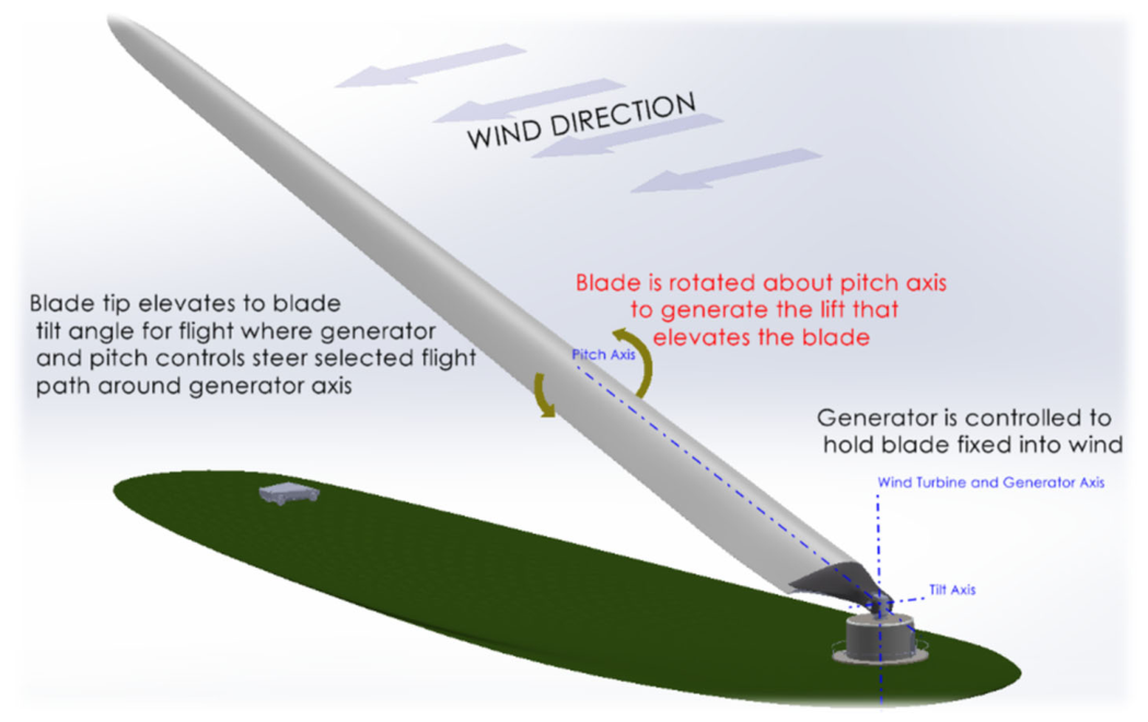
Figure 2.
AAWT prototype (a) schematic drawing of the prototype tilting with a tilt angle of 12◦ and (b) top view of angles and forces acting on the blade.
Figure 2.
AAWT prototype (a) schematic drawing of the prototype tilting with a tilt angle of 12◦ and (b) top view of angles and forces acting on the blade.
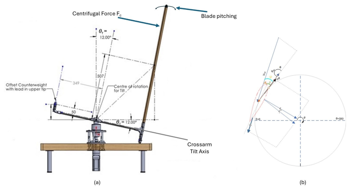
Figure 2.
The relationship between the tilt angle and pitch angle on the equilibrium curve provides the balance between aerodynamic forces and centrifugal forces acting on the rotor of an AAWT. The shaded area is the blade stall area that the control system should avoid.
Figure 2.
The relationship between the tilt angle and pitch angle on the equilibrium curve provides the balance between aerodynamic forces and centrifugal forces acting on the rotor of an AAWT. The shaded area is the blade stall area that the control system should avoid.
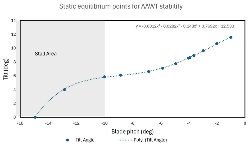
Figure 3.
The block diagram of the feedforward plus feedback controller for the tilt system of the AAWT.
Figure 3.
The block diagram of the feedforward plus feedback controller for the tilt system of the AAWT.
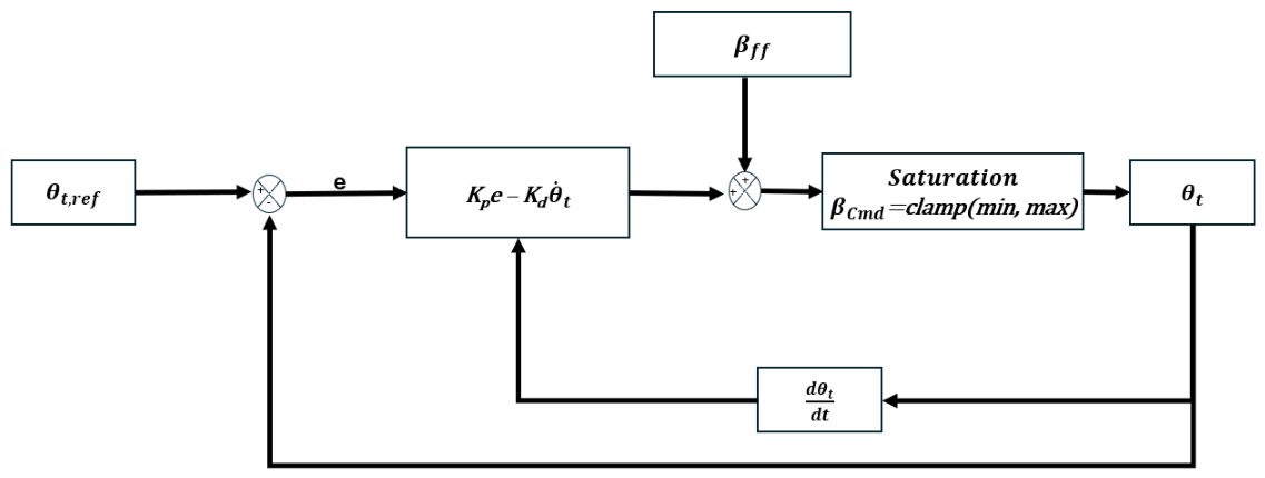
Figure 4.
Block diagram of the implemented dynamic tilt model for the AAWT, integrated with the feedforward-feedback PD controller.
Figure 4.
Block diagram of the implemented dynamic tilt model for the AAWT, integrated with the feedforward-feedback PD controller.
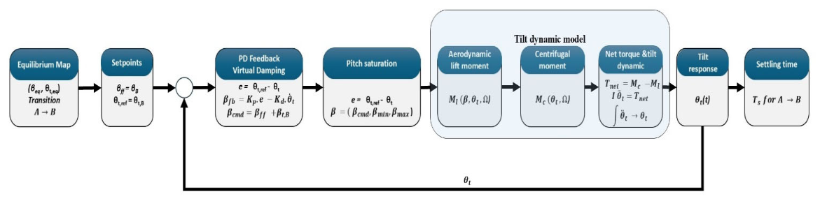
Figure 5.
Tilt angle transient response to pitch step change comparison with no control, P- control, feedforward and PD controller at the same operating conditions.
Figure 5.
Tilt angle transient response to pitch step change comparison with no control, P- control, feedforward and PD controller at the same operating conditions.
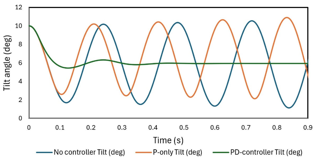
Figure 6.
Tilt angle system response for different rotor speeds 100, 200 and 300.
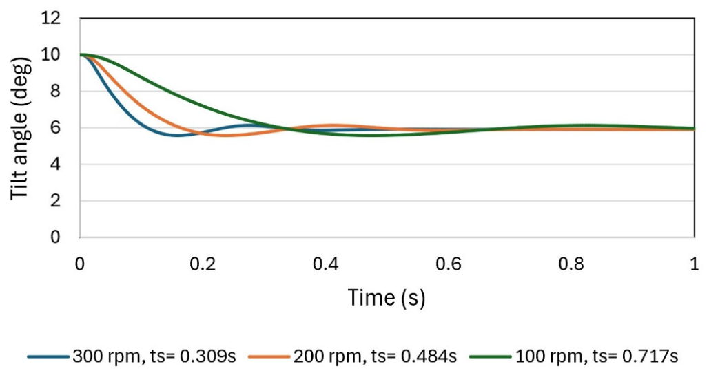
Figure 7.
(a) Settling time as a function of rotor speed of the AAWT under the PD controller dynamic model and (b), Kd gain scheduling for the same test condition of pitch step change from -3◦ to -10◦ and tilt angle from 10◦ to 6◦.
Figure 7.
(a) Settling time as a function of rotor speed of the AAWT under the PD controller dynamic model and (b), Kd gain scheduling for the same test condition of pitch step change from -3◦ to -10◦ and tilt angle from 10◦ to 6◦.
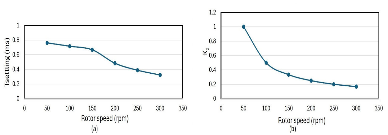
Figure 8.
Evolution of parameters during change of pitch angle from -3◦ to -10 ◦.using a feedforward PD controller (a) aerodynamic lift moment, centrifugal moment and net torque and (b) tilt angle response to the same response in.
Figure 8.
Evolution of parameters during change of pitch angle from -3◦ to -10 ◦.using a feedforward PD controller (a) aerodynamic lift moment, centrifugal moment and net torque and (b) tilt angle response to the same response in.
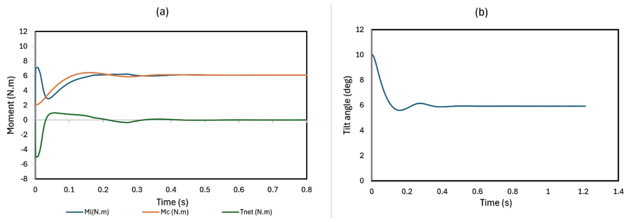

Table 1.
Key parameter values of the AAWT model.
| Parameter | value |
| Nominal rotational speed (rpm) | 300 |
| Number of blades | 1 |
| Blade airfoil | NACA0018 |
| Rotor radius [m] | 0.38 |
| Chord length [m] | 0.12 |
| Span [m] | 0.92 |
| Aspect ratio | 7.7 |
| Air density [kg/m3] | 1.2 |
| Minimum manufacturing mass per unit area [kg/cm2] | 1 |
| Moment of inertia [Kg.m2] | 0.1 |
Table 2.
Tilt angle dynamic model transition for movement between different operating equilibrium points (A to B).
Table 2.
Tilt angle dynamic model transition for movement between different operating equilibrium points (A to B).
| Pitch A | Pitch B | Tilt A | Tilt B | Settling time (s) |
| -0.02 | -2.6723 | 12 | 10 | 0.299 |
| -2.6723 | -4.7118 | 10 | 8 | 0.439 |
| -4.7118 | -9.8476 | 8 | 6 | 0.228 |
| -9.8476 | -12.8478 | 6 | 4 | 0.495 |
| -2.6723 | -9.8476 | 10 | 6 | 0.228 |
| -0.02 | -9.8476 | 12 | 6 | 0.199 |
Disclaimer/Publisher’s Note: The statements, opinions and data contained in all publications are solely those of the individual author(s) and contributor(s) and not of MDPI and/or the editor(s). MDPI and/or the editor(s) disclaim responsibility for any injury to people or property resulting from any ideas, methods, instructions or products referred to in the content. |
© 2026 by the authors. Licensee MDPI, Basel, Switzerland. This article is an open access article distributed under the terms and conditions of the Creative Commons Attribution (CC BY) license (http://creativecommons.org/licenses/by/4.0/).
Copyright: This open access article is published under a Creative Commons CC BY 4.0 license, which permit the free download, distribution, and reuse, provided that the author and preprint are cited in any reuse.