

Submitted:
09 September 2026
Posted:
09 September 2026
You are already at the latest version
Abstract
Virtual synchronous generator (VSG) has been proven as a promising control strategy for grid-forming (GFM) converters, which is applicable for power system with high penetration of converter interfaced generation. However, different with real synchronous generator (SG) consisting of copper-iron, VSG is essentially power semiconductor device with poor overcurrent capability. Current saturation limit is usually employed in VSG to prevent overcurrent, which may bring transient voltage/current source switching mode (TVCSM) and deteriorate VSG’s transient synchronizing stability. In this paper, the transient stability of VSG-based GFM converter is focused on, with the effect of TVCSM considered especially. First, concerning VSG’s virtual rotor motion influenced by TVCSM, a switching dynamic model is developed to depict VSG’s synchronizing behavior. It is identified that TVCSM introduces switching dynamics and reshapes the equivalent P-δ curve of VSG’s virtual rotor motion. Then, the impact mechanism of TVCSM on the transient synchronizing stability is clearly revealed based on the acceleration/deceleration area method. Analysis results indicate that TVCSM increases acceleration area and decreases maximum deceleration area, worsening transient stability. To quantitatively assess the impact of TVCSM on the transient stability furtherly, a novel analysis idea combining phase portrait method and inverse trajectory method is proposed to accurately estimate critical clearing angle (CCA) and critical clearing time (CCT). Finally, the influence factors including power reference, maximum allowable current and grid impedance are investigated. MATLAB/Simulink simulations are presented to verify the theoretical analysis.
Keywords:
current limiting
; grid-forming (GFM) converter
; transient stability
; transient voltage/current source switching mode (TVCSM)
; virtual synchronous generator (VSG)
1. Introduction
With the accelerated transformation of energy structure globally, the proportion of renewable energy generation with voltage source converters (VSCs) as grid interfaces is rapidly increasing in modern power system [1]. Currently, grid-following (GFL) control is commonly employed in VSCs, which track terminal voltage through phase-locked loop to synchronize with AC grid [2]. Yet, the high penetration of converter interfaced generation results in the grid presenting low inertia and weak damping. Grid-forming (GFM) converters such as virtual synchronous generators (VSGs) are considered as a viable solution, generating synchronization phase based on power control and actively participating in grid regulation [3]. VSG imitates the dynamic characteristics of synchronous generator (SG) and may suffer from similar synchronizing stability issues under disturbances, which has attracted increasing attention in industry and academia.
In the last decade, the small-signal stability of GFM converters has been extensively studied and many scholars have made outstanding contributions [4,5,6,7]. In [4], a linearized model is developed to assess the power oscillation risk of VSG. Based on eigenvalue analysis, increasing damping coefficient and grid impedance is more beneficial to improve the small-signal stability. In [5], the dq-frame impedance model of VSG is established. Small-signal stability is explored from source-load interactions in the low-frequency range. In [6] and [7], an analogized Heffron-Phillips model of VSG-based GFM converter is developed and complex torque method is used to reveal the synchronizing oscillation mode damping. It indicates that control loops may introduce negative damping torque deteriorating the VSG’s small-signal stability. Extensive literatures carry out such studies, which give a deeper comprehension on the small-signal stability of GFM converters. Yet, the analysis method based on linearized model is concerned only with the synchronizing dynamics around steady-state operating point.
In general, disturbances, large or small, occur in the power grid all the time. GFM converters are at risk of losing synchronizing with AC grid under large disturbance conditions [8,9,10,11]. In [8], a comparative study of GFM converters based on different control schemes is carried out. It reveals that VSG-based GFM converter may undergo transient instability due to insufficient damping of inertial response, even if the equilibrium points exist after fault. In [9,10], the Lyapunov-based stability criterion is employed to evaluate the VSG’s transient stability. The attraction domain is closely related to grid strength and control parameters. In [11], the energy function model of GFM converter is developed. The stability boundary under different grid conditions is investigated from the perspective of energy conversion. Yet, GFM converters are essentially power semiconductor devices with poor overcurrent capability unlike SGs. Consequently, current limiting methods are incorporated into the control system to prevent overcurrent damage, which may deeply change the VSG’s transient synchronizing behaviors [12]. This vital factor is ignored in the stability analysis of above studies.
Currently, common current limiting strategies are classified into two types: current reference limiting and virtual impedance. Virtual impedance is an indirect strategy to achieve current limiting by reducing voltage reference [13]. It may not be effective in suppressing current peaks if the parameters are not properly preset [14]. In contrast, the current reference limiting strategy has better steady-state performance [12] and is easy for implementation, which is employed and focused on in this paper. Recently, some scholars have conducted studies on the transient stability of GFM converters with current reference limiting [15,16,17,18,19,20,21,22,23]. It has been reported in [15] that the synchronizing dynamics of GFM converters with current limiting is deeply changed due to current saturation under grid fault conditions. In [16,17,18], based on droop-controlled GFM converter, it focuses on the existence of post-fault equilibrium points and then reveals the negative impact of current limiting on transient stability. Yet, for VSG-based GFM converter, sufficient deceleration area after fault clearing is also a necessary condition for maintaining transient stability. In [21], the transient stability assessment of VSG with current limiting is experimentally carried out. Complementarily, the transient stability of VSG is quantitatively studied but the damping effect is neglected [22]. In [23], the transient instability mechanism of VSG with current limiting during grid fault is investigated, but the synchronizing dynamics after fault clearing is not considered. Thus, the transient stability analysis of GFM converters with current limiting is significant but inadequate, which urgently needs to be further explored.
In this paper, the transient stability of VSG-based GFM converter is focused on, with the effect of transient voltage/current source switching mode (TVCSM) induced by current limiting considered especially. Compared with existing works, the main contributions and novelties of this paper are in three aspects:
- (1)
- An equivalent motion model with switching logic is developed to depict the VSG’s transient synchronizing behaviors, where TVCSM reshapes power angle curve and adjusts equivalent driving force.
- (2)
- Based on the acceleration/deceleration area method, the impact mechanism of TVCSM on the VSG’s transient stability is explored, which is manifested as increasing acceleration area and decreasing deceleration area.
- (3)
- A novel analysis idea combining phase portrait method and inverse trajectory method is proposed to quantitatively assess the VSG’s transient stability with damping considered, and the main influencing factors are investigated.
The rest of this paper is organized as follows. In Section 2, a synchronizing dynamic model of VSG considering TVCSM is developed. Based on the developed mode, the impact mechanism of TVCSM on the transient stability is clearly revealed based on the acceleration/deceleration area method in Section 3. In Section 4, the transient stability quantitative assessment is carried out. A novel analysis idea combining phase portrait method and inverse trajectory method is presented to accurately estimate critical clearing angle (CCA) and critical clearing time (CCT). In Section 5, the influencing factors are investigated based on acceleration/deceleration area method and CCA/CCT quantitative assessment. Finally, Section 6 concludes this paper.
2. Transient Switching Dynamic Model of VSG
2.1. Equivalent Motion Model of VSG
The typical topology of VSG connected to AC grid is shown in Figure 1. A multilayer cascade control structure is employed by VSG to mimic the dynamics of synchronous generator (SG). The outer control loops including active power control based on virtual rotor motion and alternating voltage control imitate SG’s inertia/damping response and voltage regulation, which usually have low bandwidth. The outer control loops generate dq-axis component order and phase information of command voltage for inner control loops. As actuator, the inner control loops including dq-axis current control and dq-axis voltage control are used to improve dynamics and protect against overvoltage or overcurrent during generating the command voltage vector, which usually have high bandwidth. To prevent overcurrent in case of grid fault, current saturation limit is applied between the dq-axis voltage control and dq-axis current control. When the command current generated by the dq-axis voltage control is within the limit range, current saturation limit does not take effect. Yet, when the command current exceeds the limit range, the real current references of dq-axis current control are fixed by the current saturation limit and do not respond to the dynamical regulation of outer control loops. VSG operates in current source mode in this situation.
Virtual rotor motion that imitates SG’s rotor motion characteristics for grid synchronization and inertia emulation is the core feature of VSG, which dominates VSG’s synchronizing dynamics. In the p.u. system, the angular frequency ωvsg and phase θvsg of VSG are expressed as
Pref is regulated by primary frequency regulation in slow timescale, which can be assumed to be constant in the virtual rotor motion analysis.
The power angle δ of VSG is generally defined as the difference between the converter synchronizing phase θvsg and grid voltage phase θg, and is given as
where ωp denotes the angular frequency deviation between VSG and AC grid.
VSG’s multilayer cascade control loops present multi-timescale dynamic characteristics. For the concerned synchronizing dynamic timescale that is dominated by VSG’s virtual rotor motion, the fast response control loops including alternating voltage control, dq-axis voltage control and dq-axis current control can be simplified to a quasi steady state model by neglecting controllers’ dynamics. The slow response control loops that adjusts Pref and Utref can be assumed to no enough time to respond, indicating that Pref and Utref can be assumed to be constant. Then VSG can be simplified to a controlled voltage source vector as shown in the upper part in Figure 2 when the current saturation limit does not take effect. Under disturbance, the amplitude of the controlled voltage source vector keeps constant at Utref. The phase of the controlled voltage source vector rotates with θvsg.
However, unlike SG, VSG is the power semiconductor device with poor overcurrent capability. Current limiting strategy is usually employed to prevent overcurrent in case of grid fault. In this paper, a current saturation limit strategy in 24 is employed and defined as
where Idqref are the current references generated by the inner dq-axis voltage control. Idq* are the real current references rectified by the current saturation limit. Imax is the maximum allowable current determined by the current capacity of VSG.
From (4), the current limiting strategy does not work when the amplitude of Idqref is smaller than Imax. Then the output voltage of VSG is driven to follow the command voltage by the voltage control loops and dq-axis current control. VSG operates in controlled voltage source mode in this situation. Yet in case of grid voltage sag fault, the generated current references Idqref may be larger than Imax for the output voltage of VSG to follow the command voltage. The current saturation limit takes effect, indicating that the voltage control loops lose effectiveness and the real current references Idq* are up to the current saturation limit in (4). VSG operates in controlled current source mode in this situation. The amplitude of the controlled current source vector keeps constant at Imax. The phase of the controlled current source vector rotates with θvsg in the same way. As a result, current saturation limit brings voltage/current source switching mode (TVCSM) for VSG as shown in Figure 2.
In voltage source mode, the active power P delivered by VSG can be expressed as
where Ug is the equivalent grid voltage vector; I is the output current vector of VSG; is the conjugate of I. Note that only grid inductance is considered here, since in power transmission scenarios there is usually Xg >> Rg.
The voltage and current vector diagram in voltage source mode is shown in Figure 3. According to the above analysis, VSG operating in voltage source mode needs to satisfy certain vector constraints, which is shown as
where Ut is the terminal voltage vector.
In voltage source mode, the output current magnitude |I| increases with the increase of power angle δ. When δ reaches the critical value δs, the output current of VSG increases to the maximum allowable current Imax, as shown in Figure 3. If the voltage and current vectors satisfy the triangle rule, δs can be calculated by the constraint equation. If a severe grid voltage dip makes the triangle rule unsatisfied, the magnitude of δs is 0. Thus, δs can be obtained by
Then the constraint in (6) can be identified by comparing δ and δs. When δ ≤ δs, the constraint I ≤Imax is satisfied and the VSG operates in voltage source mode.
If δ > δs, the output current exceeds the maximum allowable current and thus triggers the current limiting. In this case, the VSG can be considered as a controlled current source, as shown in Figure 2. In current source mode, the phase dynamics of current vector is still dominated by rotor swing equation. Differently, the output current amplitude Imax is directly determined by (4). In synchronizing dynamics, the output active power in current source mode is given as
where Imax is the maximum output current vector; • means the dot product operation of vectors.
According to (1), (3), (5) and (8), the synchronizing dynamic differential equation of VSG can be described as
where
The equivalent motion model of VSG considering TVCSM can be developed as shown in Figure 4. The critical value δs is referred to as the TVCSM angle. Obviously, this is a synchronizing motion model with switching logic. With normal operating conditions, the VSG is equivalent to a controlled voltage source and its active power is determined by (5). When δ increases above the threshold δs, the VSG is considered as a controlled current source and its active power is given by (8). In the transient process, VSG presents the power characteristics switching between voltage source mode and current source mode due to current limiting. Thus, TVCSM reshapes the P-δ curve of VSG, which deeply affects the VSG’s synchronizing dynamics.
2.2. P-δ Curve Reshaping Analysis
Generally, the power angle characteristics of VSG ignoring TVCSM are consistent with those of SG and can be described by (5). The P-δ curve is determined by the sine function of voltage source mode only, as shown by the blue dotted curve in Figure 5. For VSG considering TVCSM, if δ > δs, the VSG will switch to current source mode as in (8). Quite differently, the P-δ curve is constructed jointly by the sine function of voltage source mode and the cosine function of current source mode, which is described by (10), as shown by the black solid curve in Figure 6. Similar to SG, the VSG’s synchronizing dynamics is driven by unbalanced torque. The intersections of equivalent mechanical torque Pref and equivalent electromagnetic torque P are stable equilibrium point (SEP) and unstable equilibrium point (UEP), whose angles are δse and δue, respectively. After the grid fault is cleared, the system will regain transient stability if the operating point can return to SEP. Conversely, if the operating point crosses UEP, the system will be transiently unstable. Based on Figure 6, TVCSM reshapes the P-δ curve of VSG and thus modifies equivalent electromagnetic torque, which inevitably affects the transient stability, as discussed in the next section.
3. Transient Synchronizing Stability Analysis
Transient stability is closely related to the acceleration and deceleration area, which is determined by the unbalanced torques Pref and P. Based on the previous analysis, the equivalent mechanical torque remains constant in both operating modes. Yet, TVCSM reshapes the P-δ curve of VSG and thus modifies equivalent electromagnetic torque. Driven by different unbalanced torques, the synchronizing dynamics of VSG considering TVCSM differs significantly from that of VSG ignoring TVCSM. In this section, the influencing mechanism of TVCSM on the transient stability is analyzed based on the acceleration/deceleration area method.
Considering a large grid voltage dip, the acceleration areas of VSG considering and ignoring TVCSM are shown in Figure 7(a) and (b), respectively. Assuming that initial operating angle δ0 and fault clearing angle δfc are the same for both cases, the difference in acceleration area is mainly related to the unbalanced torque. Ignoring TVCSM, the equivalent electromagnetic torque during fault is determined by the sine function of voltage source mode, as shown in Figure 7(a). The kinetic energy Eki accumulated during fault is equivalent to acceleration area Sa1, which can be calculated as
where Vgref is the residual voltage of the AC grid after a fault.
Considering a severe voltage dip, i.e., satisfying , TVCSM angle δs during grid fault is 0 according to (7). More specifically, VSG will switch to current source mode directly after a fault occurs due to δ0 > δs = 0.
Thus, when TVCSM is considered, the equivalent electromagnetic torque during fault is determined by the cosine function of current source mode only, as shown in Figure 7(b). The kinetic energy Ekc accumulated during fault is equal to the sum of acceleration area Sa2 and Sa3, which can be calculated as
It is seen that acceleration area Sa2 is approximately equal to acceleration area Sa1. Yet, Sa3 is the additional acceleration area introduced by TVCSM. Thus, TVCSM changes the unbalanced torque, resulting in the VSG with a larger acceleration area. That is, the VSG considering the effect of TVCSM will accumulate more kinetic energy during grid fault, which is not conducive to maintaining transient stability.
The comparison of feasible deceleration area is shown in Figure 6 (c) and (d). For VSG ignoring TVCSM, the equivalent electromagnetic torque after fault clearing is still determined by the sine function of voltage source mode. Quite differently, for VSG considering TVCSM, the equivalent electromagnetic torque after fault clearing is determined by both the sine function of voltage source mode and the cosine function of current source mode. When δ is smaller than δs, the equivalent electromagnetic torque depends on the sine function. And if δ > δs, the equivalent electromagnetic torque is given by the cosine function. It is seen that the sine function of voltage source mode is significantly higher than the cosine function of current source mode, which results in a significant reduction of feasible deceleration area, i.e., Sd2 << Sd1. The reduced deceleration area due to TVCSM is Sd3, as shown by the gray region in Figure 6 (d).
Based on the above analysis, the transient stability comparison of VSG considering and ignoring TVCSM with the same fault clearing angle δfc are shown in Figure 6 (e) and (f). Since TVCSM reshapes the P-δ curve, the acceleration and deceleration areas of VSG change significantly with different unbalanced torques. Ignoring TVCSM, there is still a large deceleration area after the fault is cleared, and thus the system is less prone to transient instability. According to Figure 6 (e), the maximum convertible potential energy Epi is equal to deceleration area Sdi and is given as
Considering TVCSM, the additional acceleration area is introduced resulting in more kinetic energy accumulated during fault, i.e., Sac1 > Sai. Moreover, the feasible deceleration area is significantly reduced due to the fact that the cosine function of current source mode is smaller than the sine function of voltage source mode after fault clearing. From Figure 6 (f), the UEP angle δue of VSG considering TVCSM is less than fault clearing angle δfc. This means that the VSG does not move into the deceleration area instead the next acceleration area Sac2 after fault clearing. Even if the SEP exists in the system after fault clearing, the VSG is doomed to transient instability due to the absence of deceleration area. As a result, TVCSM changes the unbalanced torque of VSG, which increases the acceleration area and decreases the deceleration area, worsening the transient stability of the system.
The transient response of angular frequency ωvsg in both cases is shown in Figure 7. A severe grid voltage dip fault is set at 1.0s with residual voltage of 0.2p.u.. The grid fault lasts for 200ms and then is cleared. It is seen that the VSG ignoring TVCSM can regain synchronizing stability after fault clearing due to its larger deceleration area. Based on the previous analysis, TVCSM introduces additional acceleration area and reduces deceleration area due to P-δ curve reshaping which significantly changes equivalent electromagnetic torque. Thus, the VSG considering TVCSM undergoes transient instability for the same fault duration as shown in Figure 7.
4. Quantitative Assessment of Transient Stability
In this section, the transient stability of VSG considering TVCSM is quantitatively assessed furtherly based on two core indexes, CCA and CCT. On the one hand, ignoring the effect of damping, CCA and CCT are calculated analytically based on equal area rule. The transient stability of VSG considering and ignoring TVCSM is quantitatively compared. On the other hand, a novel analysis idea combining phase portrait method and inverse trajectory method is presented to approximately estimate the transient stability of VSG with the damping considered. In the phase plane, the intersection of forward acceleration state trajectory and backward deceleration state trajectory identifies the CCA.
Neglecting the damping effect, the VSG system is energy conservative. In the transient process, kinetic energy Ek and equivalent potential energy Ep are converted to each other, and the total energy remains constant. According to equal area rule and Figure 8, the CCA of VSG considering TVCSM satisfies
Among them, δ0, δs and δue are calculated separately as
Then, combing (14)-(17), the analytical expression of CCA for VSG considering TVCSM is obtained as
where
Further, the numerical method 26 is employed to calculate CCT. Similarly, the transient stability of VSG ignoring TVCSM can be quantitatively assessed based on CCA and CCT. With different power reference Pref, the comparisons of the transient stability for VSG considering and ignoring TVCSM are shown in Table 1.
The results indicate that both CCA and CCT of VSG considering TVCSM are much smaller than that of VSG ignoring TVCSM. That is, TVCSM greatly reduces the stability domain and thus deteriorates the transient stability of VSG. The quantitative study well validates the conclusions of mechanism analysis.
Quantitative Evaluation of CCA and CCT with Damping Considered
With the damping considered, there is not only energy transformation between kinetic energy Ek and equivalent potential energy Ep but also energy dissipated by damping in the transient process. Thus, the results of CCA and CCT calculations neglecting damping are conservative due to the neglect of energy dissipation. In order to more accurately quantify the transient stability of VSG considering TVCSM, the analysis idea combining phase portrait method and inverse trajectory method is employed.
First, the whole grid fault process is divided into two stages: fault duration and fault recovery. The state trajectories inside the two stages are discussed separately. In fault duration stage, the synchronizing dynamic differential equation with the damping considered is given as (23) based on the developed model in Figure 4.
By numerical calculation, the time forward integration of (23) from δ0 yields the forward acceleration state trajectory in fault duration stage, as shown in Figure 9.
Then, the synchronizing dynamic differential equation with the damping considered in fault recovery stage is represented as
where
The backward deceleration state trajectory can be easily obtained based on the inverse trajectory method [27]. The time backward integration of (24) is equivalent to the time forward integration of the following system.
Nonlinear systems (24) and (26) have the same state trajectory in the phase plane but with opposite trajectory direction. (26) is the inverse trajectory system of (24). The backward deceleration state trajectory in fault recovery stage obtained by numerical integration of (26) from δue is shown in Figure 9. The x-axis is power angle δ. And the y-axis is angular frequency deviation ωp, which reflects the kinetic energy Ek = (Jω2p)/2 of the state point. The intersection of forward acceleration state trajectory and backward deceleration state trajectory implies that the difference between accumulated kinetic energy and damped dissipation energy in fault duration stage is equal to the sum of consumed kinetic energy and damped dissipation energy in fault recovery stage. Thus, the power angle δcc corresponding to the intersection of state trajectories is CCA. Based on the CCA obtained from phase portrait, the CCT can be similarly calculated by numerical method. According to the parameters given in the Appendix, the CCA and CCT with the damping considered are calculated as 0.5rad and 90ms, as shown in Figure 9. Compared with the results 0.39rad and 61ms in Table I, it is seen that the transient stability assessment neglecting the effect of damping is more conservative and the damping term significantly increases the transient stability margin of VSG.
5. Simulation Validations
In this section, the effects of power reference, maximum allowable current and grid impedance on the transient stability of VSG considering TVCSM are investigated based on acceleration/deceleration area method and CCA/CCT quantitative assessment. Besides, detailed simulations are carried out in MATLAB/Simulink to verify the correctness of theoretical analysis.
Figure 10 shows the influence of power reference Pref on the acceleration and deceleration area of VSG considering TVCSM. Obviously, Pref directly determines the equivalent mechanical torque. Thus, the acceleration area decreases and the maximum deceleration area increases with the decreasing of Pref.
Figure 11 shows the transient stability assessment results with different power reference Pref. From (15) and (17), both initial power angle δ0 and UEP angle δue are related with Pref. With the decreasing of Pref, δ0 decreases while δue increases. Since Pref determines the magnitude of equivalent mechanical torque, decreasing Pref slows down the acceleration of forward state trajectory and speeds up the deceleration of backward state trajectory. Thus, both CCA and CCT increase as Pref decreases, and the transient stability is enhanced. This means that the improved control strategy of enhancing transient stability by reducing power reference during fault is still applicable to the scenario where TVCSM is considered.
The simulation results are given in Figure 12, where the main parameters are kept constant as in Appendix, except for the studied influencing factor. A severe grid voltage dip fault is set at 6s with the residual voltage of 0.2p.u. It is seen that VSG with Pref of 1.0p.u. can regain synchronizing stability if the fault is 0.09s, while transient instability occurs if FCT is 0.1s. Thus, the CCT of EMT model is between 0.09s and 0.1s, which is very close to the CCT of 90ms as the quantitative estimation in Figure 11. Similarly, the CCT of EMT model with Pref of 0.8p.u. is between 0.17s and 0.18s, and the CCT with Pref of 0.6p.u. is between 0.3s and 0.31s, both of which are close to the results of theoretical analysis in Figure 11. The simulation results verify the correctness of transient stability quantitative assessment.
5.1. Influence of Maximum Allowable Current
Figure 13 shows the influence of maximum allowable current Imax on the acceleration and deceleration area of VSG considering TVCSM. The equivalent mechanical torque is only depended on Pref, which does not change varying with Imax.
According to (10), the sine function in voltage source mode is independent of Imax while the cosine function in current source mode is closely related to Imax. Thus, the equivalent electromagnetic torque tends to rise as Imax increases in the fault
duration and recovery stages. The acceleration area decreases and the maximum deceleration area increases with the increasing of Imax.
Figure 14 shows the transient stability assessment results with different maximum allowable current Imax. (15)-(17) indicates that Imax does not affect δ0 but significantly changes δue and δs. Based on the previous analysis, it is known that the equivalent electromagnetic torque increases with increasing Imax while the equivalent mechanical torque remains constant. More specifically, a larger Imax will correspond to a smaller unbalanced torque difference in the fault duration and recovery stages. Thus, increasing Imax will slow down the acceleration of forward state trajectory and speed up the deceleration of backward state trajectory. The CCA is obtained from the intersection of state trajectories and then the CCT is estimated as in Figure 14. It can be seen that as Imax increases, both CCA and CCT increase and the transient stability is improved. This illustrates that the VSG with strong overcurrent capability has better transient stability and is easier to maintain synchronizing after fault clearing.
The simulation results are given in Figure 15, with the same fault settings as in Figure 12. It is seen that the CCTs of EMT model are 0.05s-0.06s, 0.15s-0.16s and 0.21s-0.22s when Imax is 1.2p.u., 2.0p.u. and 3.0p.u., respectively. The CCTs based on quantitative assessment are 46ms, 138ms and 215ms, respectively. The theoretical analysis and simulation results are in good agreement.
5.2. Influence of Grid Impedance
Figure 16 shows the influence of grid impedance Xg on the acceleration and deceleration area of VSG considering TVCSM. Similarly, the equivalent mechanical torque is not influenced by Xg. Contrary to Imax, the sine function in voltage source mode is related to Xg, while the cosine function in current source mode is independent of Xg. Thus, in fault duration stage, the equivalent electromagnetic torque keeps unchanged with the increasing of Xg. The equivalent electromagnetic torque tends to drop as Xg increases in fault recovery stage. Yet, initial power angle δ0 is strongly influenced by Xg. The acceleration area variation needs to be discussed in the specific scenario. The maximum deceleration area decreases with the increasing of Xg.
Figure 17 shows the transient stability assessment results with different grid impedance Xg. Based on (15)-(17), it is known that δ0 and δs are closely related to Xg while δue does not depend on the magnitude of Xg. When Xg is 0.2p.u., 0.3p.u. and 0.5p.u., the quantitatively calculated CCA and CCT are 0.48rad and 97ms, 0.52rad and 83ms, 0.64rad and 59ms, respectively. It can be seen that the CCA of VSG considering TVCSM increases but the CCT decreases as Xg increases. The reason for this difference is that increasing Xg reduces the maximum deceleration area, but it also significantly increases initial power angle δ0. Thus, although the variation Δδ decreases in transient process, the magnitude of δcc = δ0 + Δδ still increases due to the larger δ0. Since Xg has little effect on the unbalanced torque in fault duration stage, CCT depends mainly on the increment Δδ, which decreases with increasing Xg due to the decreasing of equivalent electromagnetic torque in fault recovery stage. As a result, as Xg increases, CCA increases and CCT decreases instead. It is easy to misjudge the effect of Xg on the transient stability of VSG considering TVCSM based on the CCA index alone. In practice, the CCT index is commonly used to guide relay protection design and should be taken into account even more.
The simulation results are given in Figure 18. It is seen that the CCTs of EMT model are 0.1s-0.11s, 0.09s-0.1s, and 0.06s-0.07s when Xg is 0.2p.u., 0.3p.u. and 0.5p.u., respectively. The simulation results are close to the quantitative assessment in Figure 17, thus verifying the validity of theoretical analysis.
6. Conclusions
In this paper, the transient stability of VSG-based GFM converter is studied, with the effect of TVCSM induced by current limiting considered especially.
First, the equivalent motion model is developed to clearly depict the VSG’s synchronizing behaviors, where TVCSM reshapes the P-δ curve and thus adjusts equivalent driving force in transient process. Further, the impact mechanism of TVCSM on the transient stability of VSG is clearly revealed based on the acceleration/deceleration area method. A novel analysis idea combining phase portrait method and inverse trajectory method is proposed to quantitatively assess the transient stability margin. Finally, the influences of power reference, maximum allowable current and grid impedance on transient stability is investigated. The valuable conclusions are as follows:
1) Based on the developed equivalent motion model, it is found that TVCSM introduces switching dynamics to VSG and significantly reshapes the equivalent power angle curve of virtual rotor motion.
2) TVCSM modifies the equivalent electromagnetic torque, resulting in a larger acceleration area and a smaller deceleration area. Both CCA and CCT of VSG are significantly reduced with TVCSM considered.
3) Decreasing power reference and increasing maximum allowable current will increase both CCA and CCT of VSG considering TVCSM. The effect of grid impedance on CCA and CCT is inconsistent, which is manifested as increasing CCA and decreasing CCT.
The works in this paper not only clearly reveal the impact mechanism of TVCSM on VSG’s transient stability, but also give a reference for improving control and relay protection design.
Author Contributions
Y.C.: methodology, formal analysis, simulation analysis and original draft; T.W.: simulation analysis and writing—review and editing; Q.H.: methodology, formal analysis, review and editing. All authors have agreed to the published version of the manuscript.
Data Availability Statement
Not applicable.
Conflicts of Interest
The authors declare no conflict of interest.
References
- Shair, J.; Li, H.; Hu, J.; Xie, X. Power system stability issues, classifications and research prospects in the context of high-penetration of renewables and power electronics. Renew. Sustain. Energy Rev. 2021, vol. 145. [Google Scholar] [CrossRef]
- Hu, Q.; Fu, L.; Ma, F.; Ji, F. Large signal synchronizing instability of PLL-based VSC connected to weak AC grid. IEEE Trans. Power Syst. 2019, vol. 34(no. 4), 3220–3229. [Google Scholar] [CrossRef]
- Zhang, H.; Xiang, W.; Lin, W.; Wen, J. Grid forming converters in renewable energy sources dominated power grid: Control strategy, stability, application, and challenges. J. Mod. Power Syst. Clean Energy 2021, vol. 9(no. 6), 1239–1256. [Google Scholar] [CrossRef]
- Sun, P.; Yao, J.; Zhao, Y.; Fang, X.; Cao, J. Stability assessment and damping optimization control of multiple grid-connected virtual synchronous generators. IEEE Trans. Energy Convers. 2021, vol. 36(no. 4), 3555–3567. [Google Scholar] [CrossRef]
- Guo, J.; Chen, Y.; Liao, S.; Wu, W.; Zhou, L.; Xie, Z.; Wang, X. Analysis and mitigation of low-frequency interactions between the source and load virtual synchronous machine in an islanded microgrid. IEEE Trans. Ind. Electron. 2022, vol. 69(no. 4), 3732–3742. [Google Scholar] [CrossRef]
- Huang, L.; Xin, H.; Wang, Z. Damping low-frequency oscillations through VSC-HVDC stations operated as virtual synchronous machines. IEEE Trans. Power Electron. 2018, vol. 34(no. 6), 5803–5818. [Google Scholar] [CrossRef]
- Qu, Z.; Peng, C. H.; Yang, H.; Srinivasan, D. Modeling and analysis of inner controls effects on damping and synchronizing torque components in VSG-controlled converter. IEEE Trans. Energy Convers. 2021, vol. 36(no. 1), 488–499. [Google Scholar] [CrossRef]
- Pan, D.; Wang, X.; Liu, F.; Shi, R. Transient stability of voltage-source converters with grid-forming control: A design-oriented study. IEEE J. Emerg. Sel. Top. Power Electron. 2020, vol. 8(no. 2), 1019–1033. [Google Scholar] [CrossRef]
- Shuai, Z.; Shen, C.; Liu, X.; Li, Z.; Shen, Z. J. Transient angle stability of virtual synchronous generators using Lyapunov’s direct method. IEEE Trans. Smart Grid 2019, vol. 10(no. 4), 4648–4661. [Google Scholar] [CrossRef]
- Zhao, F.; Shuai, Z.; Huang, W.; Shen, Y.; Shen, Z. J.; Shen, C. A unified model of voltage-controlled inverter for transient angle stability analysis. IEEE Trans. Power Del. 2022, vol. 37(no. 3), 2275–2288. [Google Scholar] [CrossRef]
- Fu, X.; Sun, J.; Huang, M.; Tian, Z.; Yan, H.; Iu, H. H.; Hu, P.; Zha, X. Large-signal stability of grid-forming and grid-following controls in voltage source converter: A comparative study. IEEE Trans. Power Electron. 2021, vol. 36(no. 7), 7832–7840. [Google Scholar] [CrossRef]
- Fan, B.; Liu, T.; Zhao, F.; Wu, H.; Wang, X. A review of current-limiting control of grid-forming inverters under symmetrical disturbances. IEEE Open J. Power Electron. 2022, vol. 3, 955–969. [Google Scholar] [CrossRef]
- Qoria, T.; Gruson, F.; Colas, F.; Denis, G.; Prevost, T.; Guillaud, X. Critical clearing time determination and enhancement of grid-forming converters embedding virtual impedance as current limitation algorithm. IEEE J. Emerg. Sel. Top. Power Electron. 2020, vol. 8(no. 2), 1050–1061. [Google Scholar] [CrossRef]
- Qoria, T.; Gruson, F.; Colas, F.; Kestelyn, X.; Guillaud, X. Current limiting algorithms and transient stability analysis of grid-forming VSCs. Electr. Power Syst. Res. 2020, vol. 189, 106726. [Google Scholar] [CrossRef]
- Xin, H.; Huang, L.; Zhang, L.; Wang, Z.; Hu, J. Synchronous instability mechanism of P-f droop-controlled voltage source converter caused by current saturation. IEEE Trans. Power Syst. 2016, vol. 31(no. 6), 5206–5207. [Google Scholar] [CrossRef]
- Huang, L.; Xin, H.; Wang, Z.; Zhang, L.; Wu, K.; Hu, J. Transient stability analysis and control design of droop-controlled voltage source converters considering current limitation. IEEE Trans. Smart Grid 2019, vol.10(no. 1), 578–591. [Google Scholar] [CrossRef]
- Fan, B.; Wang, X. Equivalent circuit model of grid-forming converters with circular current limiter for transient stability analysis. IEEE Trans. Power Syst. 2022, vol. 37(no. 4), 3141–3144. [Google Scholar] [CrossRef]
- Fan, B.; Wang, X. Fault recovery analysis of grid-forming inverters with priority-based current limiters. IEEE Trans. Power Syst. 2023, vol.38(no. 6), 5102–5112. [Google Scholar] [CrossRef]
- Zhuang, K.; Xin, H.; Hu, P.; Wang, Z. Current saturation analysis and anti-windup control design of grid-forming voltage source converter. IEEE Trans. Energy Convers. 2022, vol. 37(no. 4), 2790–2802. [Google Scholar] [CrossRef]
- Zhang, Y.; Zhang, C.; Yang, R.; Molinas, M.; Cai, X. Current- constrained power-angle characterization method for transient stability analysis of grid-forming voltage source converters. IEEE Trans. Energy Convers. 2023, vol.38(no. 2), 1338–1349. [Google Scholar] [CrossRef]
- Saffar, K. G.; Driss, S.; Ajaei, F. B. Impacts of current limiting on the transient stability of the virtual synchronous generator. IEEE Trans. Power Electron. 2023, vol. 38(no. 2), 1509–1521. [Google Scholar] [CrossRef]
- Rokrok, E.; Qoria, T.; Bruyere, A.; Francois, B.; Guillaud, X. Transient stability assessment and enhancement of grid-forming converters embedding current reference saturation as current limiting strategy. IEEE Trans. Power Syst. 2022, vol. 37(no. 2), 1519–1531. [Google Scholar] [CrossRef]
- Wang, G.; Fu, L.; Hu, Q.; Liu, C.; Ma, Y. Transient synchronization stability of grid-forming converter during grid fault considering transient switched operation mode. IEEE Trans. Sustain. Energy 2023, vol.14(no. 3), 1504–1515. [Google Scholar] [CrossRef]
- Giroux, P.; Sybille, G. Static Synchronous Compensator (STATCOM) Used for Midpoint Voltage Regulation on a 500kV Transmission Line; MathWorks, Inc.: Natick, MA, USA, 2006. [Google Scholar]
- Blasko, V.; Kaura, V. A new mathematical model and control of a three-phase AC-DC voltage source converter. IEEE Trans. Power Electron. 1997, vol. 12(no. 1), 116–123. [Google Scholar] [CrossRef]
- Kundur, P. Power System Stability and Control; McGraw-Hill: New York, NY, USA, 1994. [Google Scholar]
- Genesio, R.; Vicino, A. New techniques for constructing asymptotic stability regions for nonlinear systems. IEEE Trans. Circuits Syst. 1984, vol. 31(no. 6), 574–581. [Google Scholar] [CrossRef]
Figure 1.
1. Typical control structure of grid-connected VSG.
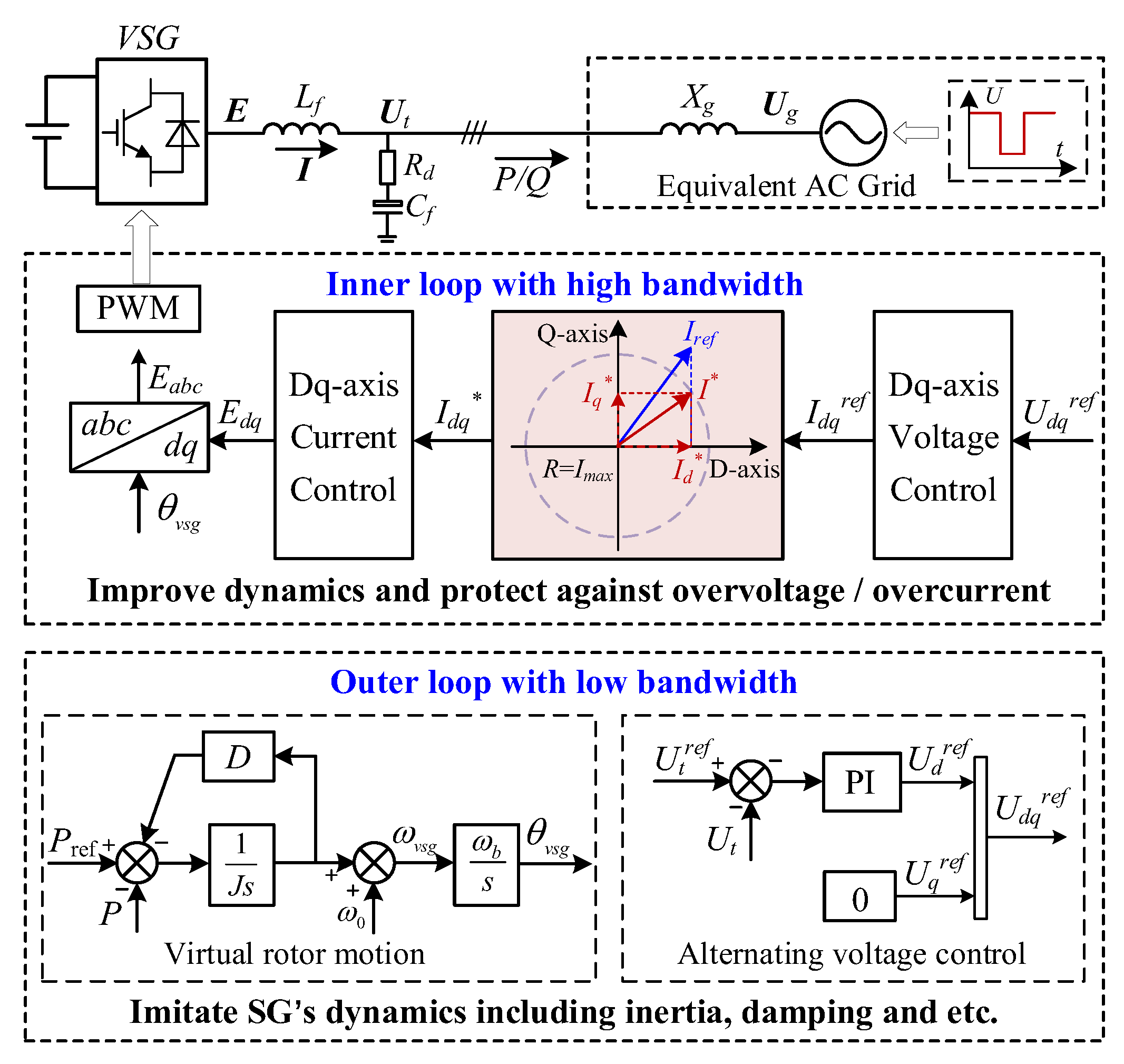
Figure 2.
. Equivalent circuit model of the VSG-based GFM converter.
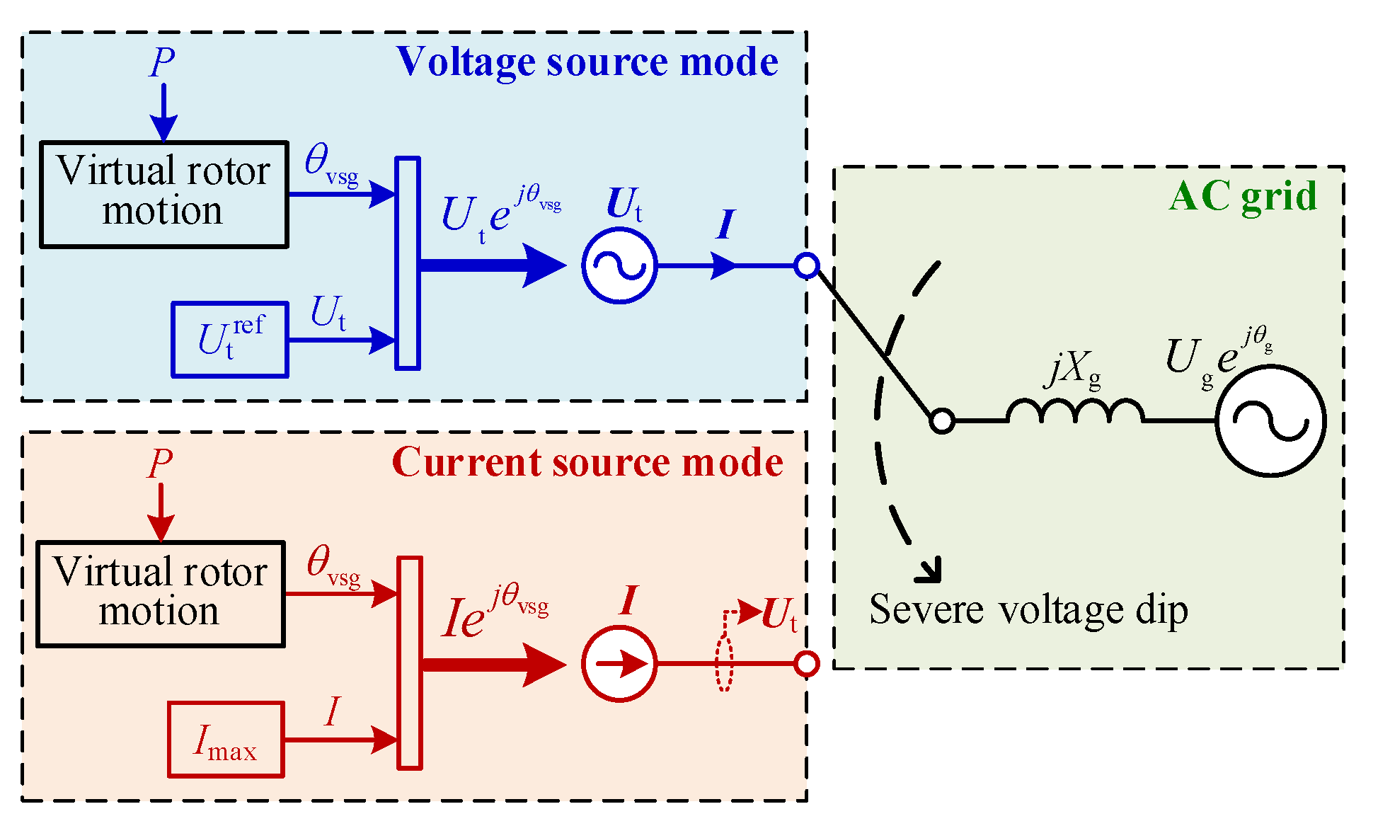
Figure 3.
. Vector diagram of VSG in voltage source mode.
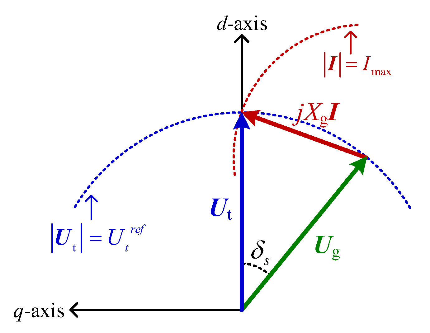
Figure 4.
. Equivalent motion model of VSG considering TVCSM.
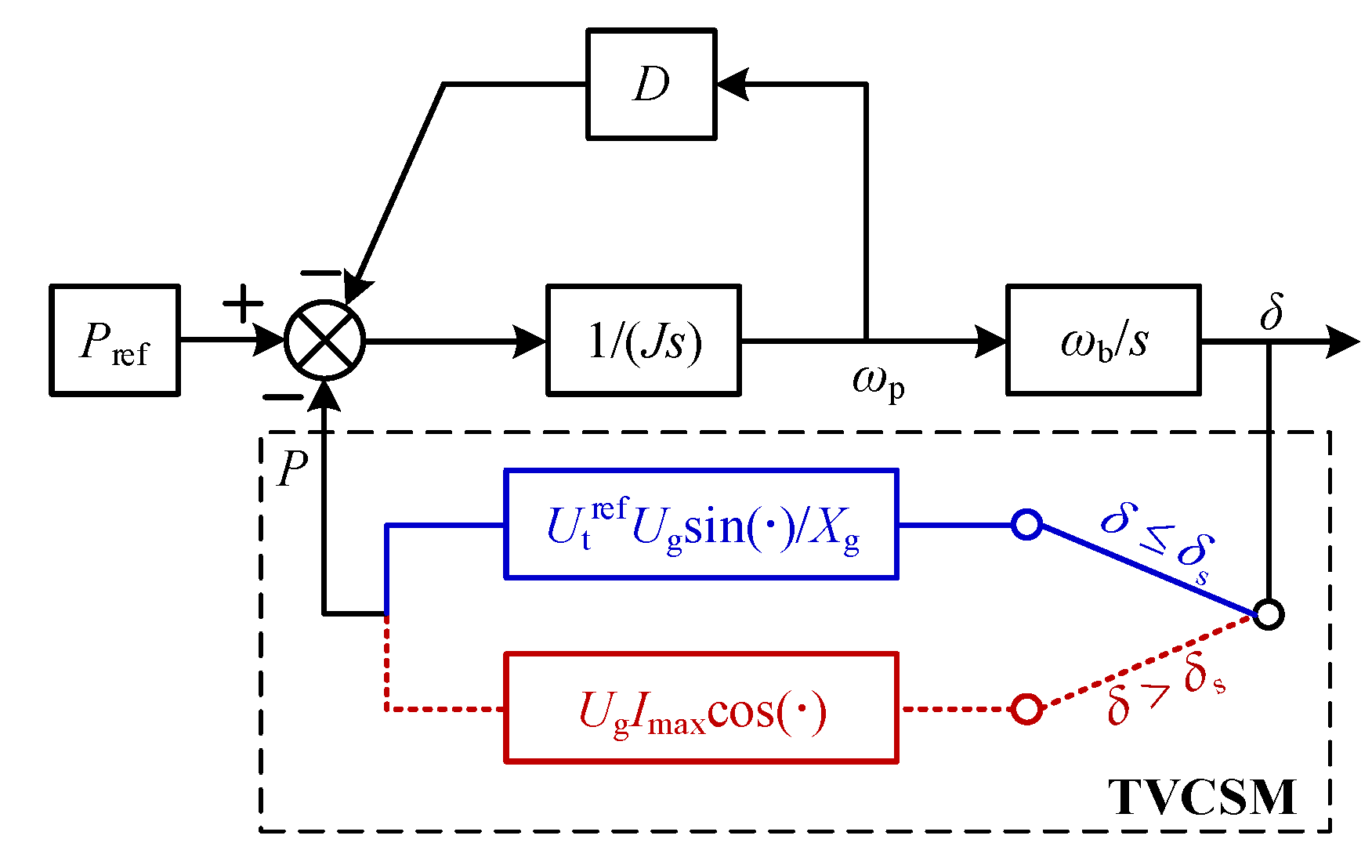
Figure 5.
. P-δ curve reshaping induced by TVCSM.
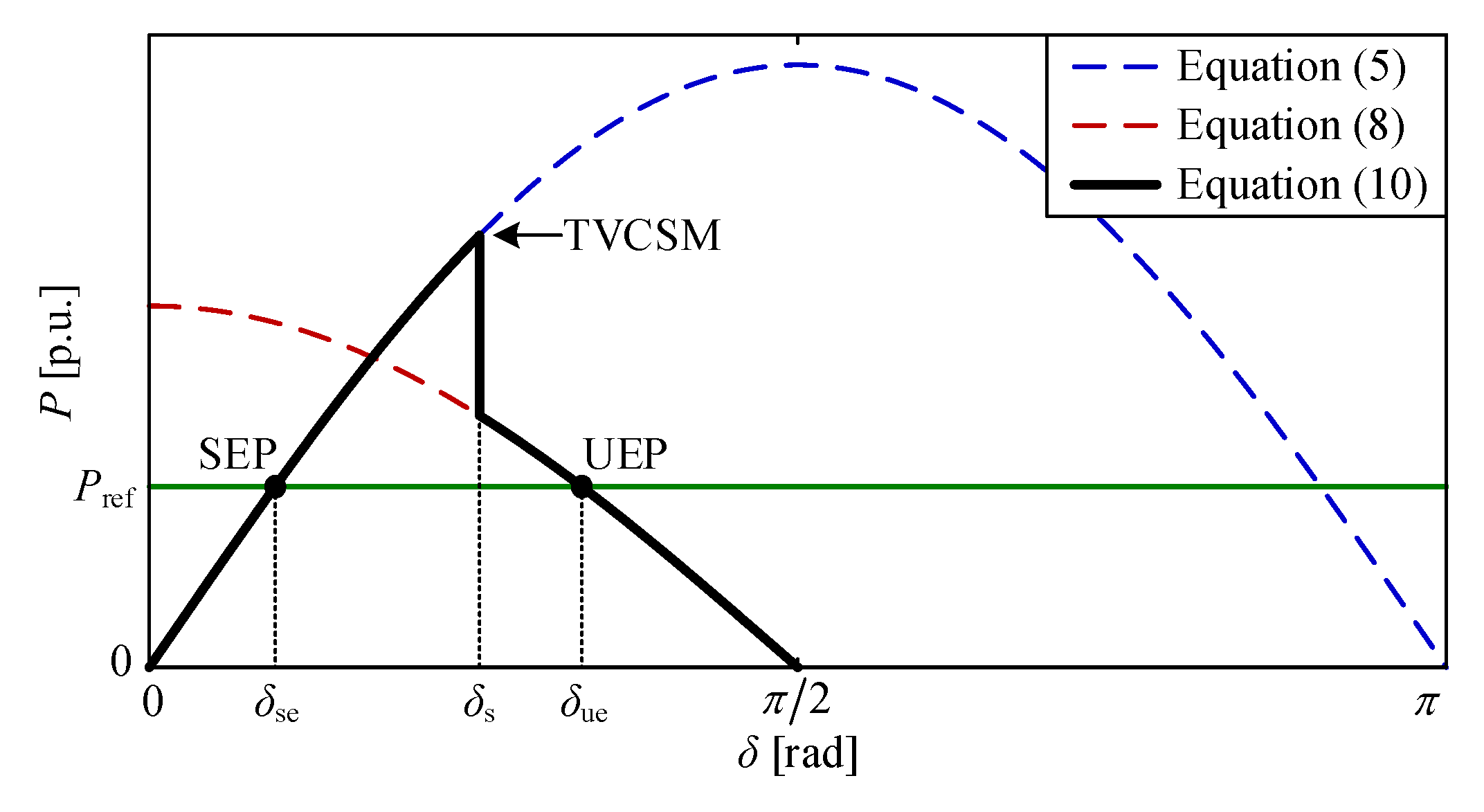
Figure 6.
. Transient stability mechanism analysis based on acceleration/deceleration area method (a) acceleration area of VSG ignoring TVCSM (b) acceleration area of VSG considering TVCSM (c) feasible deceleration area of VSG ignoring TVCSM (d) feasible deceleration area of VSG considering TVCSM (e) transient stability analysis of VSG ignoring TVCSM (f) transient stability analysis of VSG considering TVCSM.
Figure 6.
. Transient stability mechanism analysis based on acceleration/deceleration area method (a) acceleration area of VSG ignoring TVCSM (b) acceleration area of VSG considering TVCSM (c) feasible deceleration area of VSG ignoring TVCSM (d) feasible deceleration area of VSG considering TVCSM (e) transient stability analysis of VSG ignoring TVCSM (f) transient stability analysis of VSG considering TVCSM.
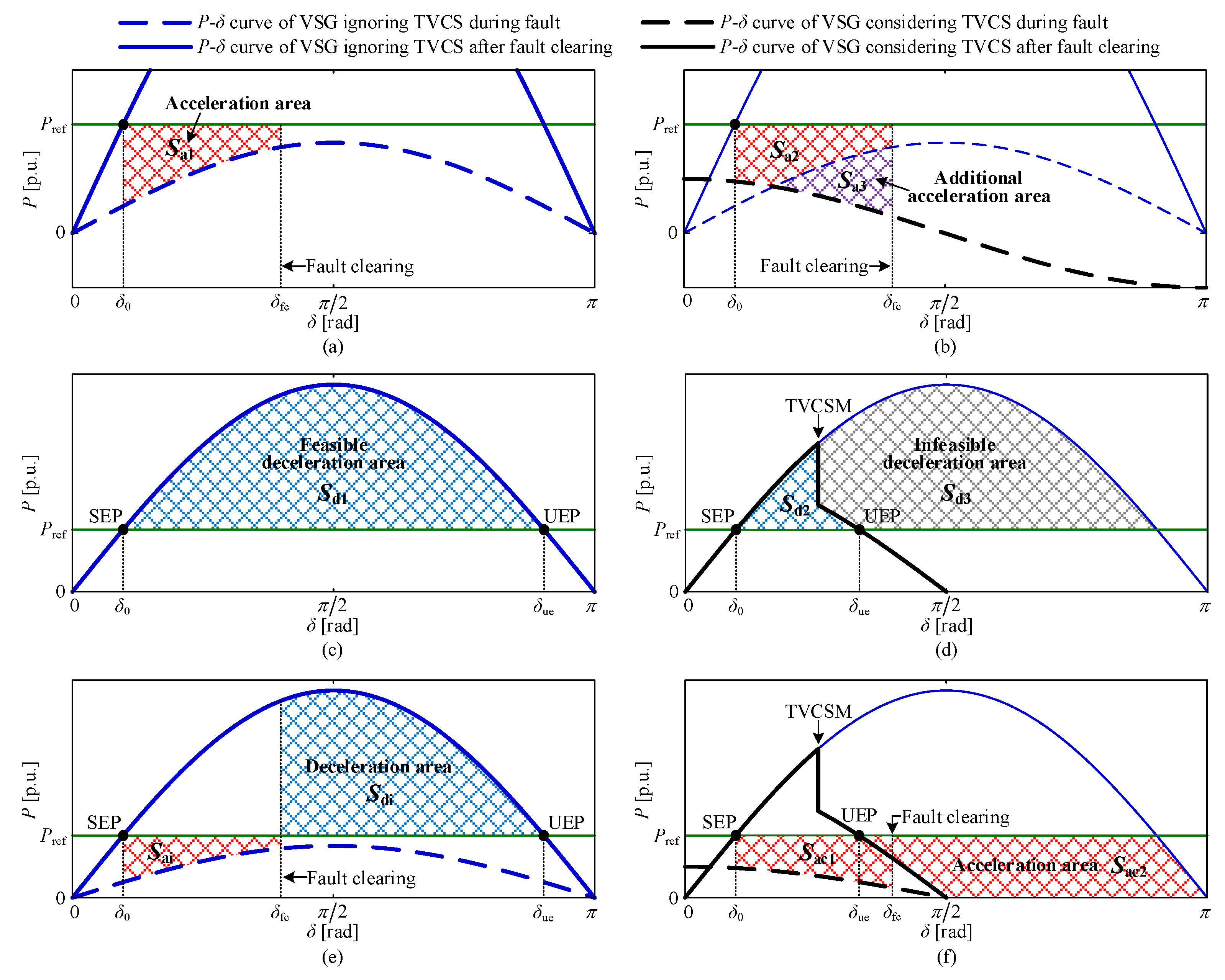
Figure 7.
. Comparison of transient response under 0.2s duration fault.
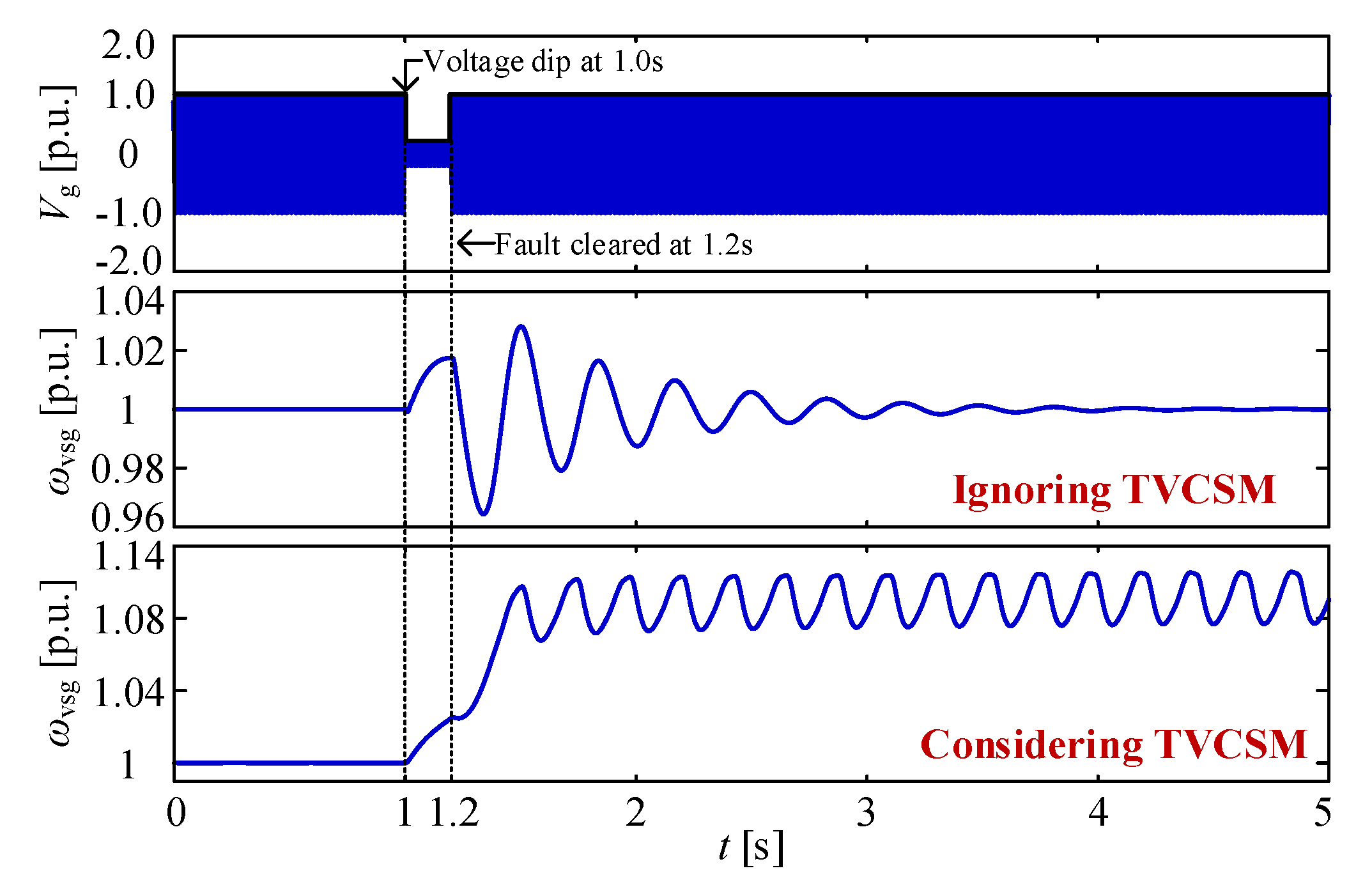
Figure 8.
Transient stability assessment based on equal area rule.
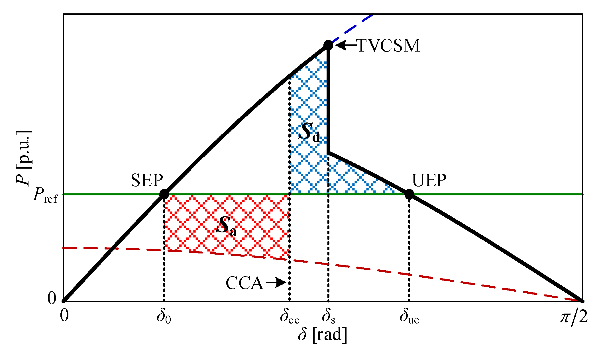
Figure 9.
Transient stability assessment based on inverse trajectory method.
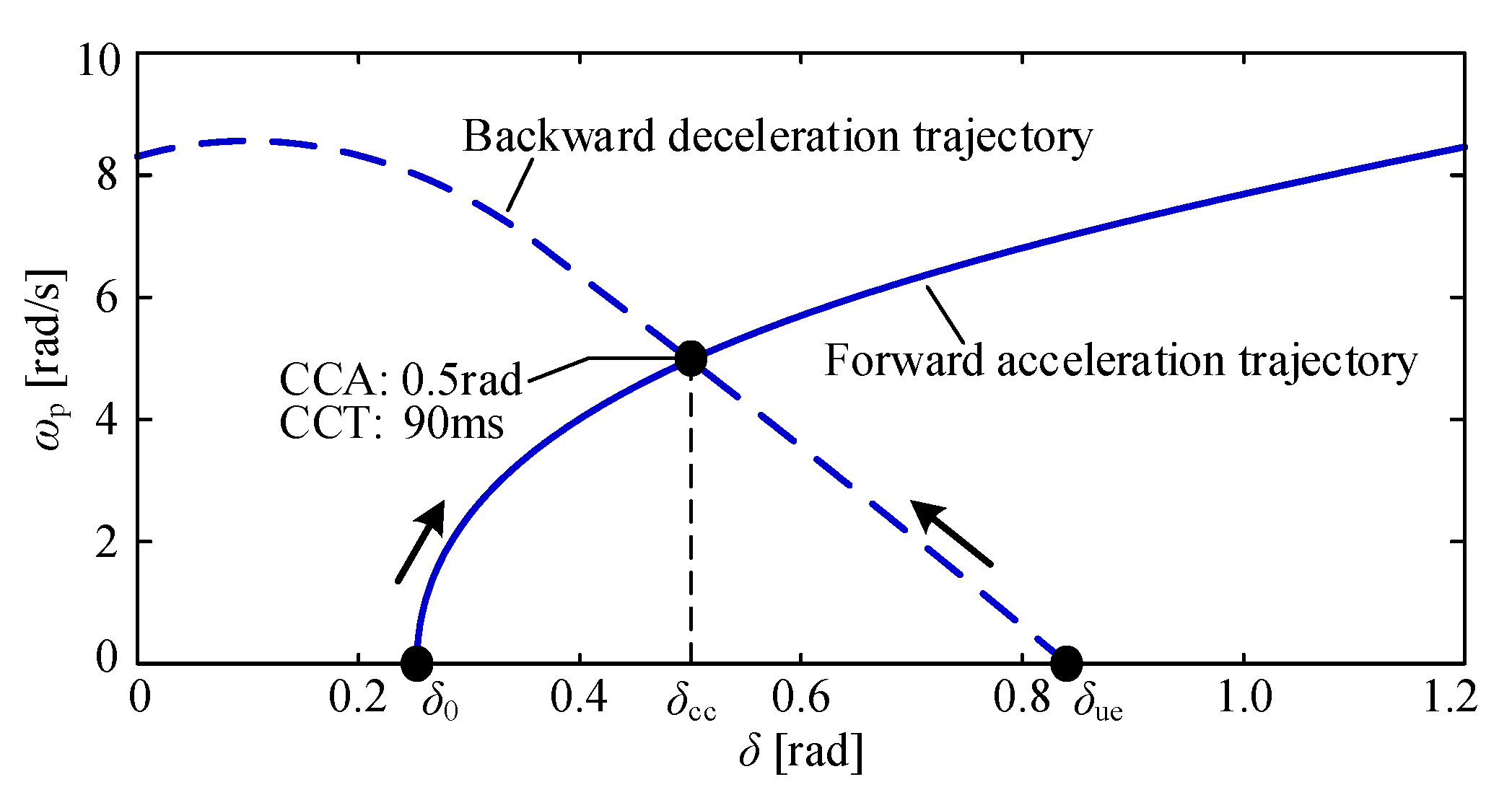
Figure 10.
The influence of Pref on acceleration and deceleration area.
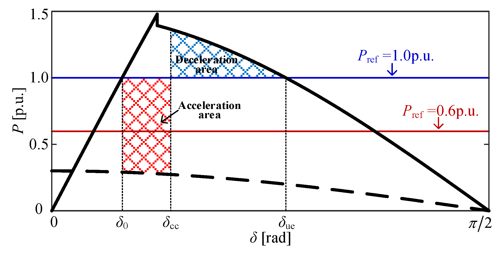
Figure 11.
Transient stability assessment with different Pref.
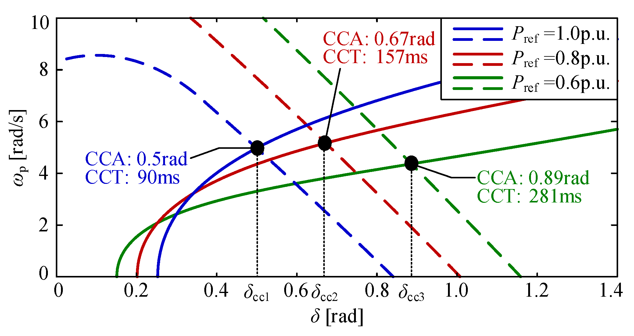
Figure 12.
Transient response with different Pref and FCT. clearing time (FCT).
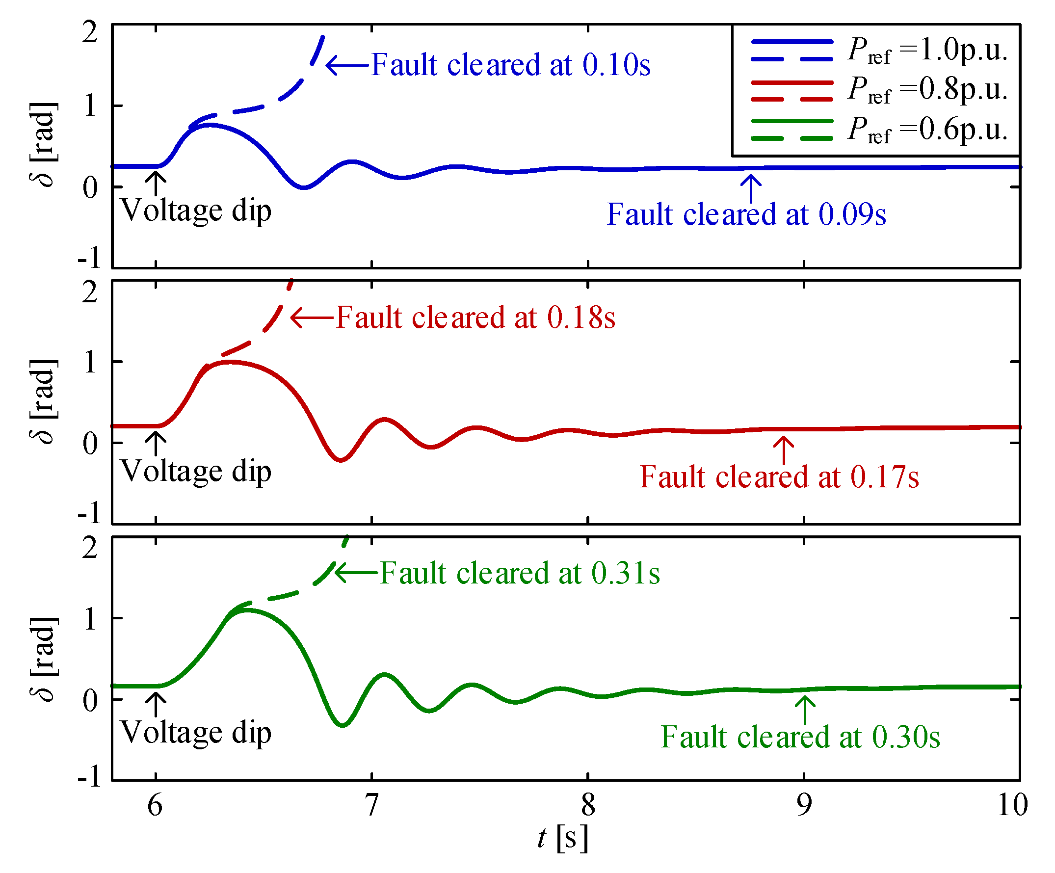
Figure 13.
The influence of Imax on acceleration and deceleration area.
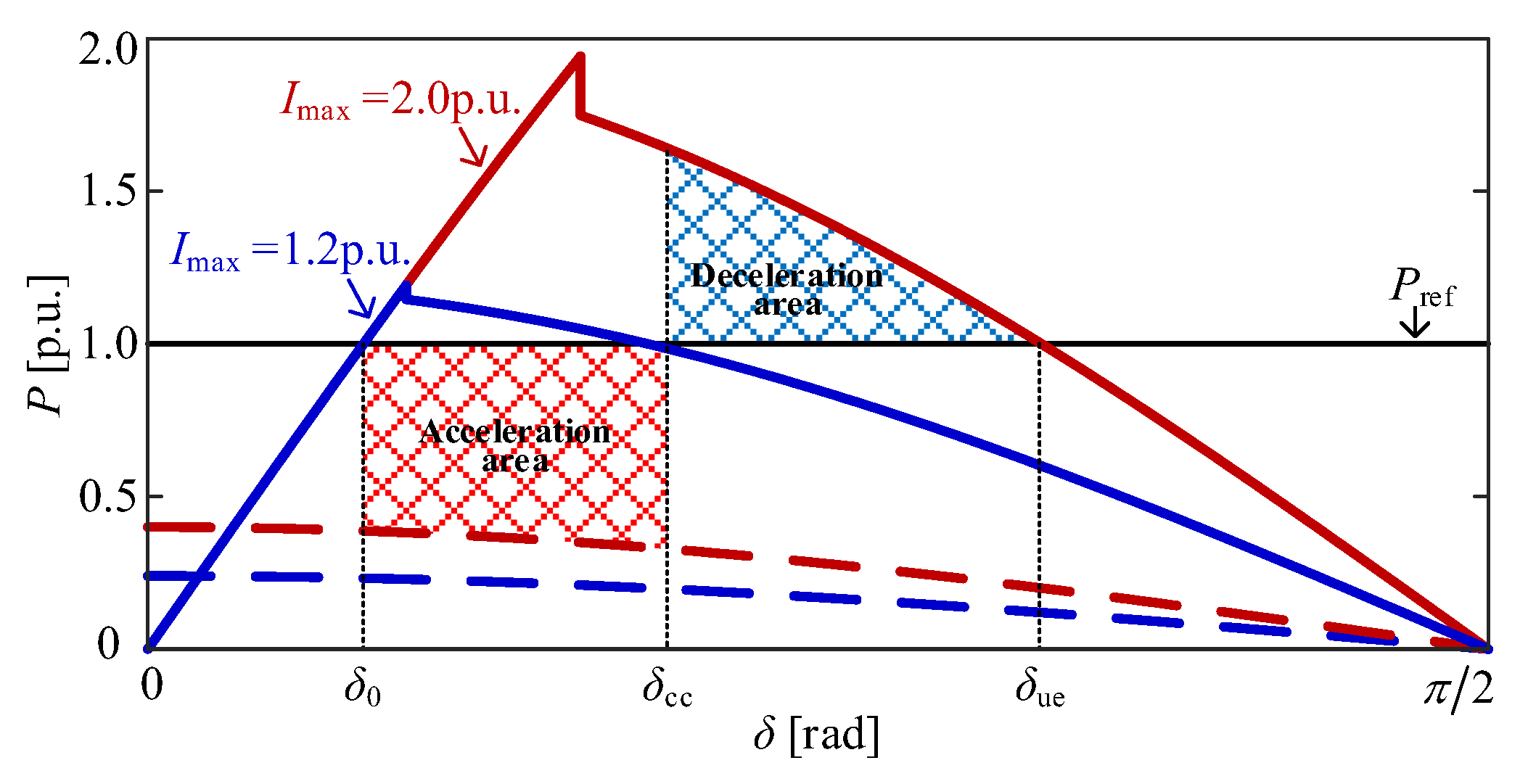
Figure 14.
Transient stability assessment with different Imax.
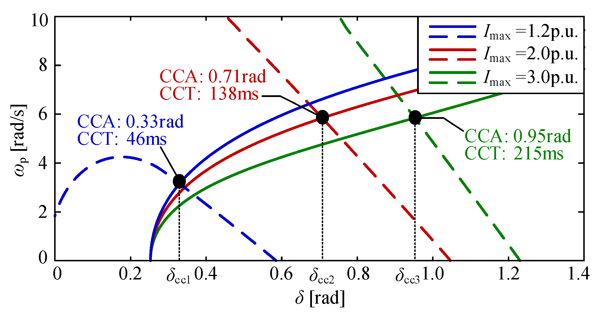
Figure 15.
Transient response with different Imax and FCT.
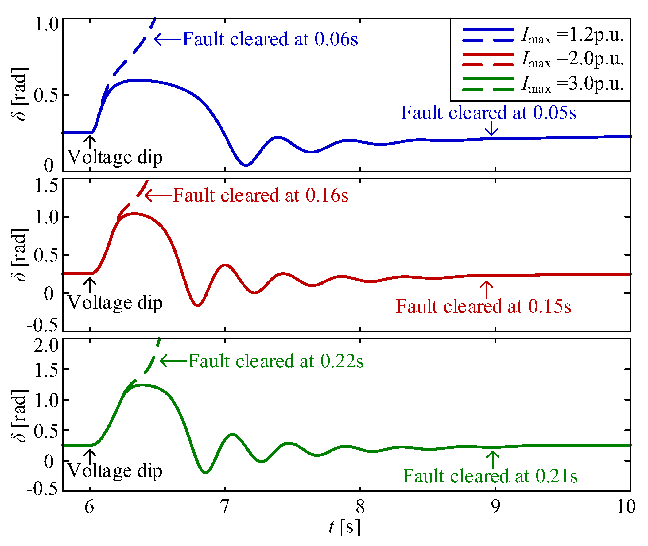
Figure 16.
The influence of Xg on acceleration and deceleration area.
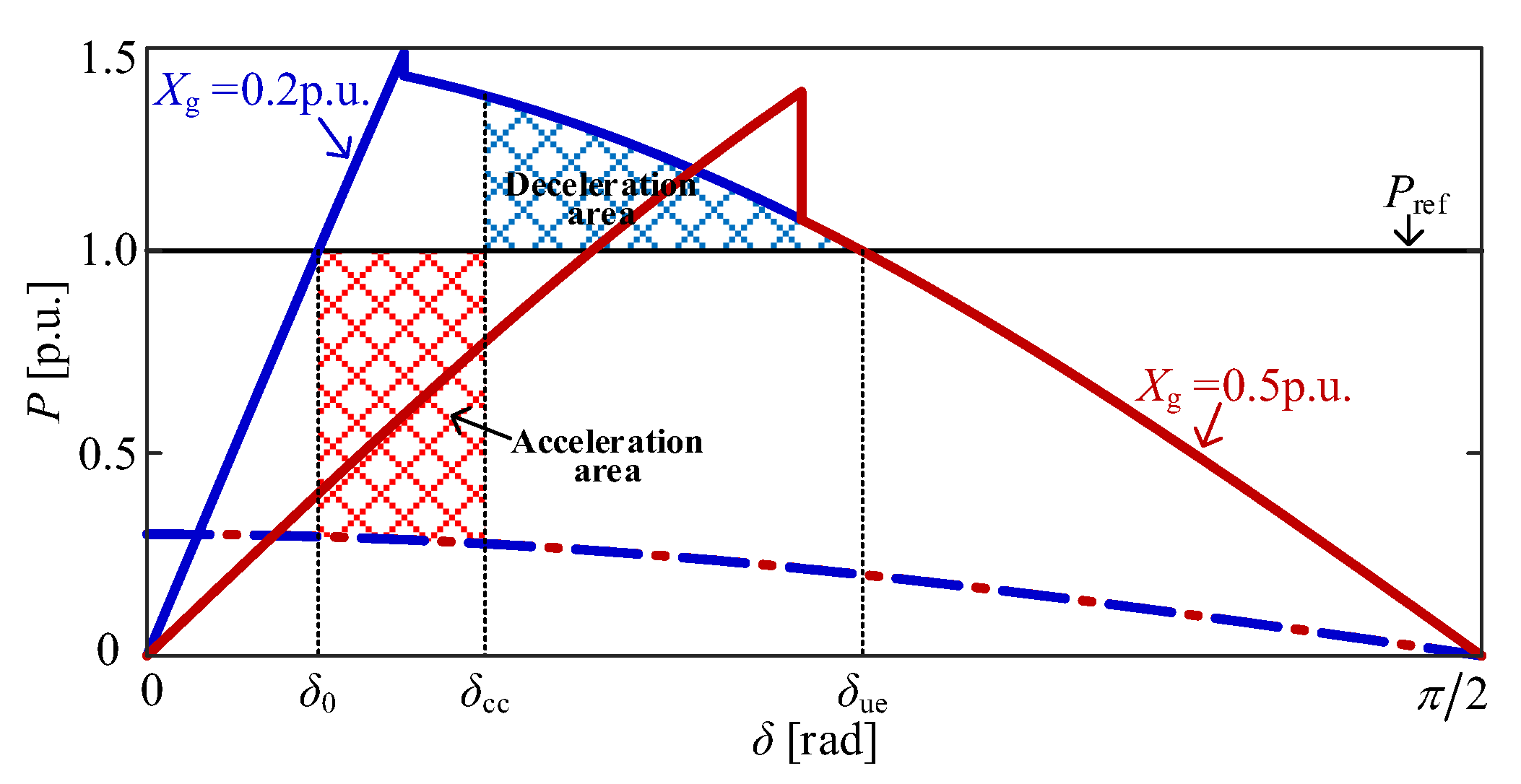
Figure 17.
Transient stability assessment with different Xg.
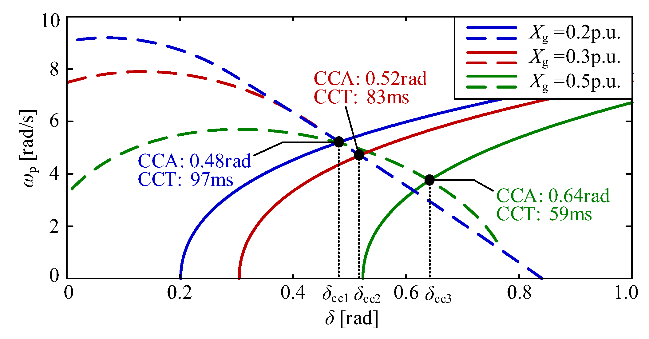
Figure 18.
Transient response with different Xg and FCT.
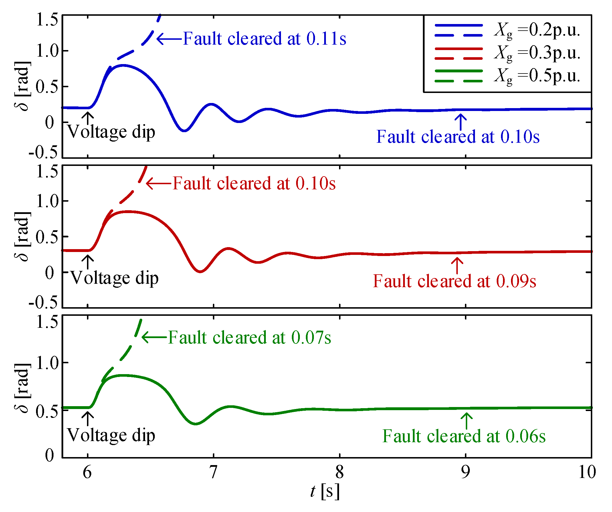

Table 1.
Comparison of CCA and CCT With Different Power Reference.
| Pref/p.u. | VSG considering TVCSM | VSG ignoring TVCSM | VSG considering TVCSM | VSG ignoring TVCSM |
|---|---|---|---|---|
| CCA/rad | CCT/ms | CCA/rad | CCT/ms | |
| 1.0 | 0.39 | 61 | 2.25 | 259 |
| 0.9 | 0.42 | 78 | 2.35 | 295 |
| 0.8 | 0.47 | 100 | 2.47 | 349 |
| 0.7 | 0.51 | 125 | 2.62 | 449 |
Disclaimer/Publisher’s Note: The statements, opinions and data contained in all publications are solely those of the individual author(s) and contributor(s) and not of MDPI and/or the editor(s). MDPI and/or the editor(s) disclaim responsibility for any injury to people or property resulting from any ideas, methods, instructions or products referred to in the content. |
© 2026 by the authors. Licensee MDPI, Basel, Switzerland. This article is an open access article distributed under the terms and conditions of the Creative Commons Attribution (CC BY) license (http://creativecommons.org/licenses/by/4.0/).
Copyright: This open access article is published under a Creative Commons CC BY 4.0 license, which permit the free download, distribution, and reuse, provided that the author and preprint are cited in any reuse.