

Submitted:
08 September 2026
Posted:
09 September 2026
You are already at the latest version
Abstract
This review provides a comprehensive analysis of the suitability of steel helical pile groups as a foundational solution for expanding energy transmission networks with specific focus on Australia. It synthesizes a wide array of research, from government policy and industry plans to geotechnical studies and engineering case histories, to evaluate the technology's performance against critical technical, logistical, and economic criteria. The analysis confirms that Australia is on the cusp of an unprecedented energy transi-tion, necessitating the rapid and efficient deployment of thousands of kilometres of new transmission infrastructure. Traditional foundation methods, such as bored Piles, are proving to be a bottleneck due to their reliance on complex logistics, extensive site work, and high material and labor costs. The findings of this review conclude that steel helical pile groups represent a superior, more resilient alternative. Their inherent advantages—including a design that funda-mentally mitigates the risks of Australia's expansive clay soils, a lower-impact installa-tion process, immediate load-bearing capacity, and a verifiable quality control method-ology—directly address the core challenges facing major projects. The use of prefabri-cated steel piles, which are manufactured in-house and can be deployed with smaller crews and equipment, dramatically reduces on-site labor hours and eliminates the need for concrete curing. Furthermore, the minimal environmental footprint, including a significantly lower embodied carbon profile, aligns with modern sustainability goals and helps secure the social license to operate for large-scale infrastructure projects. This review recommends that helical pile technology be considered a primary solution in the early stages of design for future transmission and renewable energy projects. To accelerate its adoption, there is a clear need for formalized, Australian-specific engi-neering guidelines and the establishment of local pilot projects to provide a definitive public demonstration of their performance, productivity, and cost-effectiveness. The strategic adoption of helical piles is not merely a matter of technical preference but a critical component of a robust, cost-effective, and sustainable approach to modernizing Australia's energy grid.
Keywords:
helical piles
; transmission tower foundations
; bored piles
; geotechnical engineering
; deep foundations
; sustainable construction
; foundation design
1. Introduction
Transmission infrastructure is the network of high-capacity power lines, towers, substations, and related equipment that transports electricity over long distances from where it is generated (like power plants) to the local distribution systems that deliver it to homes and businesses. Think of it as the "interstate highway system for electricity." Just as highways move large volumes of cars and trucks between regions, the transmission grid moves massive amounts of electricity between power sources and population centers.
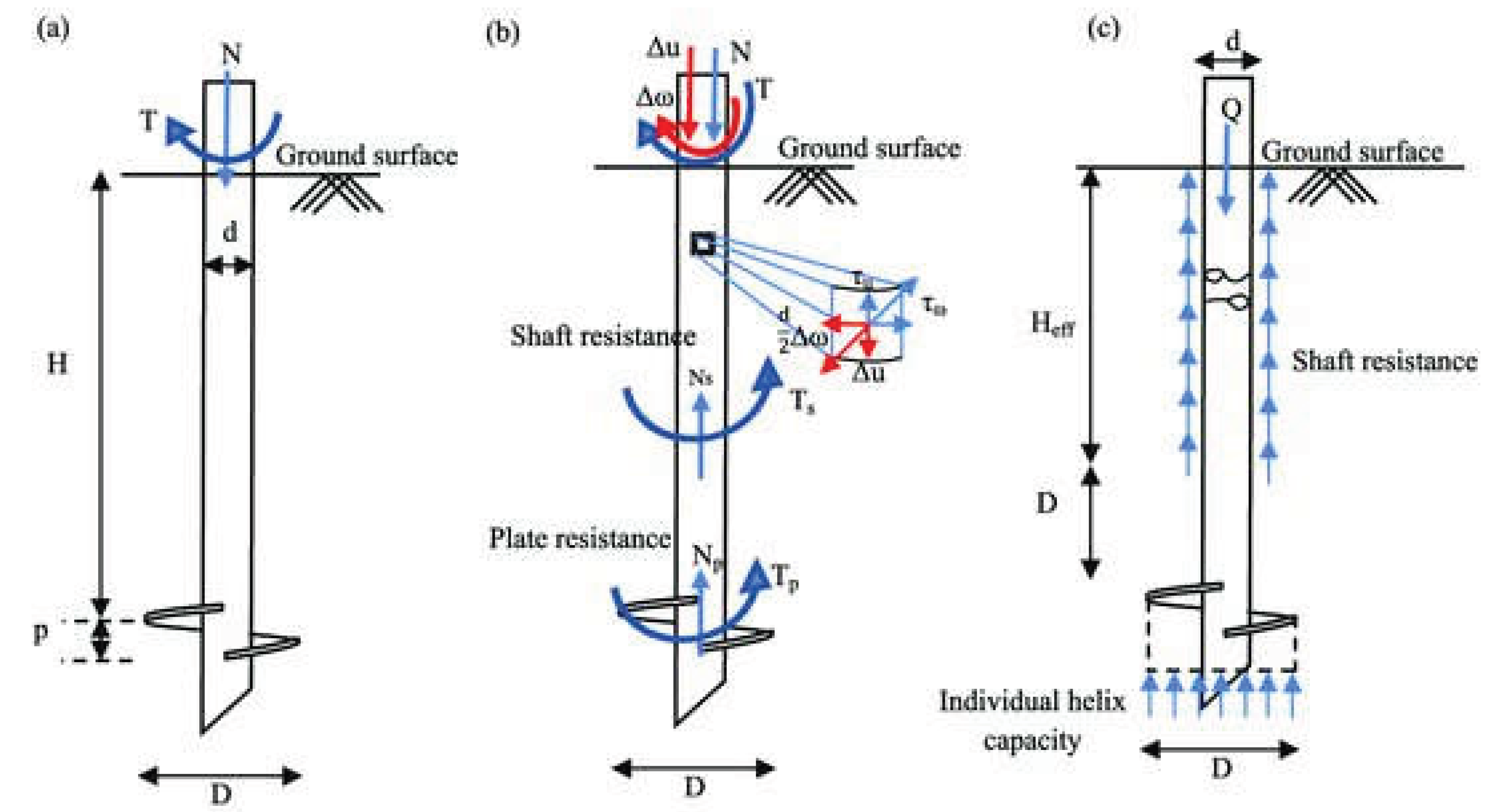
Foundations are not just a main part of transmission infrastructure; they are the critical, non-negotiable base upon which the entire system depends. Their importance cannot be overstated. While the tall towers and high-voltage wires are the most visible parts of the transmission system, the foundations are their unseen, indispensable anchor. They are the first component built and the most critical to the system's structural integrity, safety, and longevity. If a foundation fails, the tower can collapse, and a single tower failure can bring down an entire line, causing a blackout for millions of people and businesses. Moreover, Transmission lines are designed to last for 50 to 100 years. The foundation must endure for this entire lifespan while being constantly subjected to weather cycles (freeze-thaw, wet-dry), corrosion from soil and water, potential seismic activity and etc. The foundation for a tower must resist four primary types of loads. Compression is the downward, crushing force from the structure's own constant weight. Tension or Uplift is the opposing upward force, typically caused by strong wind attempting to pull one side of the foundation out of the ground. The most critical load is the Overturning Moment, a powerful twisting action created by wind pressure that tries to rotate the entire tower over. This moment is the root cause of the extreme compression and tension on opposite sides of the base. Finally, Shear or Lateral Load is the direct sideways shove from the wind, trying to slide the foundation horizontally through the soil [1]. Shows the schematic of loads applied on a helical pile [2].
Figure 1.
Schematic of a deeply embedded helical pile with a single helix: (a) installation forces and key dimensions; (b) forces on the shaft and helical plate and shear stresses generated along the shaft; (c) Individual plate bearing for helical piles under axial compression [2].
Figure 1.
Schematic of a deeply embedded helical pile with a single helix: (a) installation forces and key dimensions; (b) forces on the shaft and helical plate and shear stresses generated along the shaft; (c) Individual plate bearing for helical piles under axial compression [2].
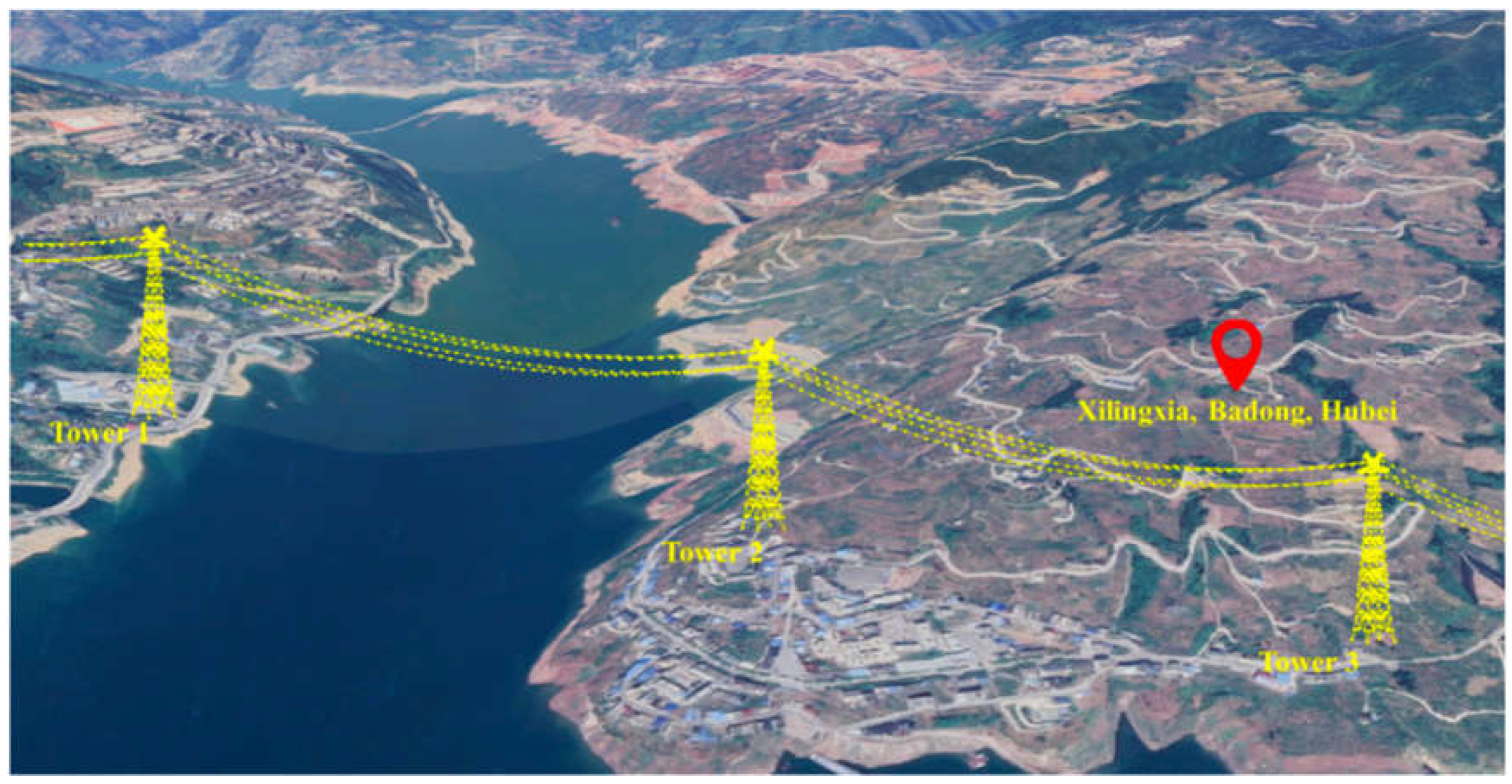
Considering all above discussed, foundations design and construction are of great importance and a small failure of foundations can lead to catastrophic results [1]. shows the transmission towers that are placed far from each other on reliable foundations, which can withstand different types of loads implied.
Figure 2.
Transmission Tower Lines [1].
Figure 2.
Transmission Tower Lines [1].
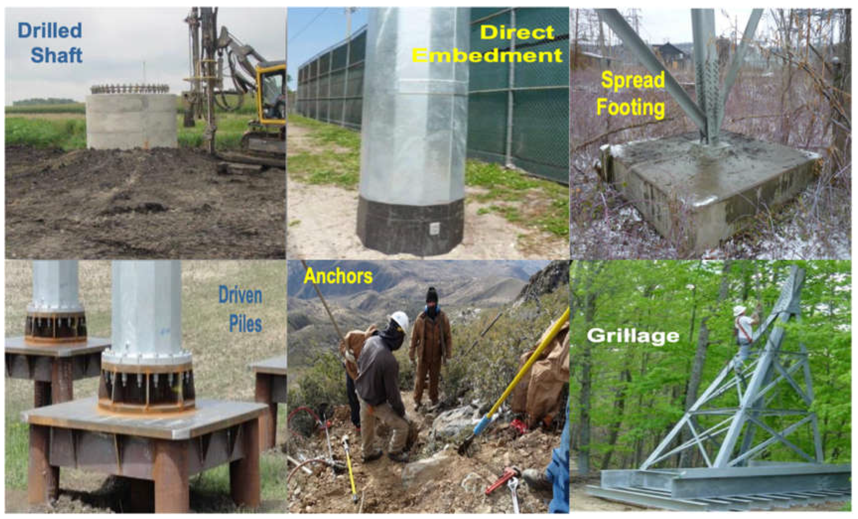
Designing an appropriate foundation is a very complicated process and there is no one-size-fits-all solution. There are several types of foundations encountered for each practice, which is entirely dependent on the local geology, soil conditions, environmental considerations, and etc. Drilled shaft, direct embedment, spread footing, grillage, driven piles and anchors are among the so many foundation types shown in [3].
Figure 3.
Several Types of Foundations [2].
Figure 3.
Several Types of Foundations [2].
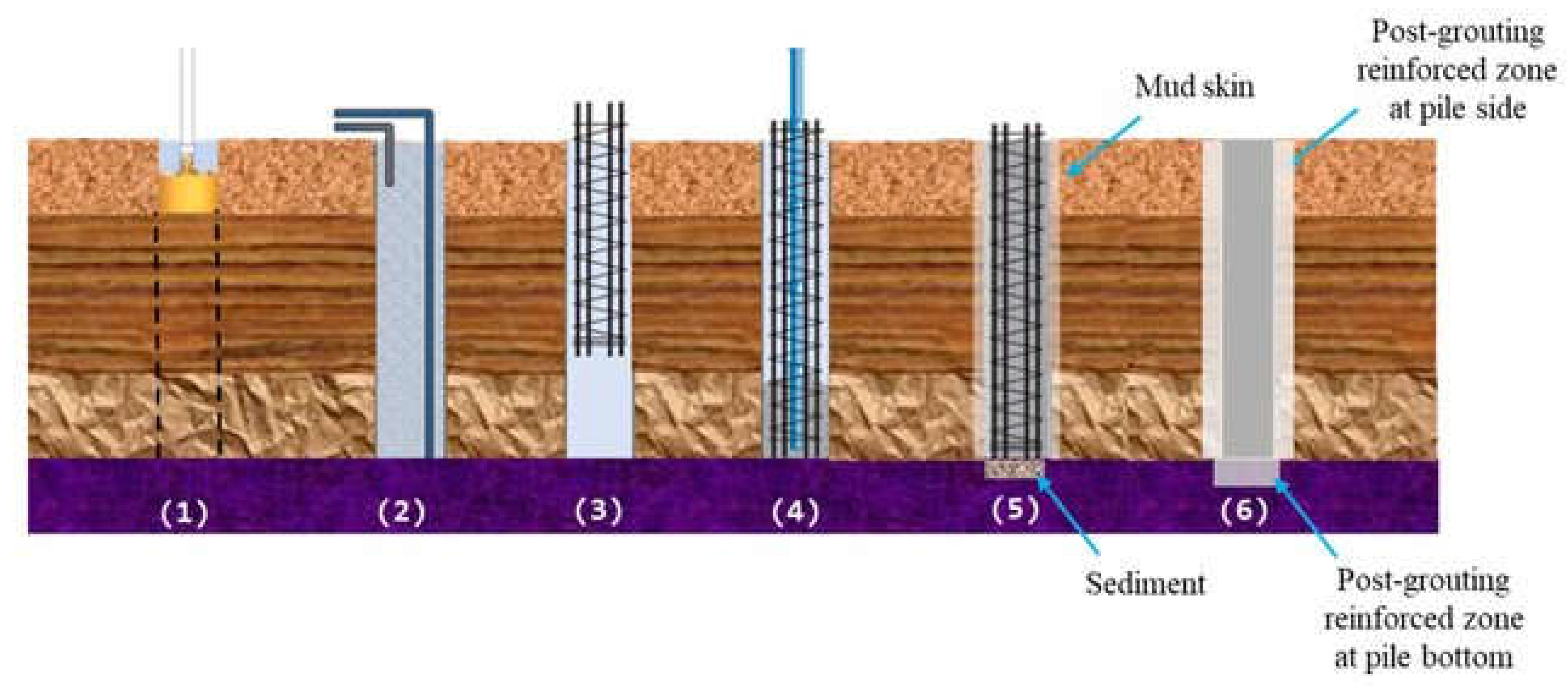
Bored piles, also known as a drilled shaft or caisson, are a fundamental and widely used type of deep foundations, and they are absolutely considered a traditional and essential method in transmission infrastructure and civil engineering as a whole. They are the essential solution when towers must be founded on stable ground that lies far beneath the surface. When you see a massive transmission tower crossing a river valley, marshland, or a seismically active area, there is a very high probability that it is securely anchored to the earth with bored piles [4]. As shown in , a bored pile is a deep foundation element constructed by drilling a cylindrical hole deep into the ground, Installing a steel reinforcement cage and filling the hole with concrete [4].
Figure 4.
Stages of bored pile construction [4].
Figure 4.
Stages of bored pile construction [4].
The pile transfers the load from the structure down to a deeper, more competent soil layer or bedrock [4]. summarizes the application of different types of foundations.

Table 1.
Application of different foundations [2].
Table 1.
Application of different foundations [2].
| Foundation type | Category | Typical use case in transmission |
|---|---|---|
| Grillage foundation | Shallow | Stable, high-capacity soil at shallow depth. Good for both compression and uplift [5]. |
| Spread footing | Shallow | Competent rock or very dense soil at the surface. Simple and cost-effective [5]. |
| Bored pile | Deep | Weak surface soils, need to reach deep bedrock, high uplift loads, difficult terrain [5]. |
| Direct embedment | Deep | A specific type for poles, where the pole itself is the foundation element [5]. |
Even though bored piles have great advantages such as high load capacity (can support immense axial and lateral loads), high adaptability (can be drilled to great depths and varying diameters to suit specific site conditions), have minimal vibration (is Ideal for sensitive sites), and moreover, can be installed in difficult ground via using techniques like casing and slurry, which allow construction in almost any soil type, but their installation and construction is engaged with different problems which limits their application [6]
Firstly, they are generally more expensive than shallow foundations due to the required equipment and materials. Huge drilling equipment and machines for making and pouring concrete into holes, all lead to high logistic costs. The transportation of this heavy equipment to the foundation site is also an extra problem which may even make a project impossible in remote areas. Moreover, the implementation of bored piles usually requires high work force, and the rate of steel installation and pouring concrete is influenced by the experience and number of steel crew. Thus, the project expenses are usually high [6].
Secondly, The construction process is less visible (underground), so rigorous inspection is needed to ensure the hole is clean, straight, and properly filled with concrete [6]. Concrete takes long time to cure and for this reason, the installation of bored piles are usually long term projects [7]. However, the production of concrete is a major global contributor to carbon emissions and concrete is an indispensable part of bored piles [8].
Finally, the environmental performance of a foundation system is an increasingly important consideration for large-scale infrastructure projects. Bored piles require the removal of large volumes of soil and replacing them in another location, which negatively influences the environment and endangers its balance [9]. Besides this, the capacity of a bored pile is highly dependent on soil conditions, requiring thorough geotechnical investigation. Before construction of a bored pile, a pre-investigation is vital, which only includes statistical sample analysis around the foundation but do not cover the entire area. The existence of soil types with different cohesion or stiffness from site to site, existence of natural obstacles, and etc. makes it very difficult to predict the load bearing capacity of a bored pile before construction [6].
Considering both pros and cons of bored piles, the disadvantages of bored piles outweigh its advantages, thus, application of novel foundations seem to be an essential need in foundation industries.
1.1. Context and Market Need: The Impetus for Transmission Expansion
Australia is undergoing a profound and rapid energy transformation, driven by a national commitment to decarbonization and the urgent need to replace aging fossil fuel assets. The Australian Government’s "Rewiring the Nation" program is a cornerstone of this policy, providing concessional finance to modernize the electricity grid and deliver new and upgraded infrastructure [10]. This initiative is designed to lower the cost of essential infrastructure for consumers and support Australia's emissions reduction targets of 43% by 2030 and net-zero emissions by 2050 [10].
The scale of this transition is immense. The Australian Energy Market Operator's (AEMO) 2024 Integrated System Plan (ISP), which serves as a roadmap for the National Electricity Market (NEM), forecasts an estimated 4,581 km of new transmission lines are needed to meet 2030 targets alone [11]. The optimal development path to net-zero by 2050 has an annualized capital cost of $122 billion [12]. AEMO projects that the investment in these transmission projects will recoup their $16 billion investment costs, save consumers a further $18.5 billion, and deliver $3.3 billion in emissions reductions [12].
This national agenda includes a number of priority transmission projects across the country [10]. In New South Wales, this includes HumeLink, the Sydney Ring, and the Victoria-New South Wales Interconnector West (VNI West) [10]. In Tasmania, the Marinus Link and North West Transmission Developments (NWTD) are receiving significant government funding [10]. The government has also agreed to support transmission upgrades in Western Australia and the Northern Territory, highlighting the national scope of the modernization effort [10].
A key challenge highlighted in AEMO's analysis is the unprecedented cost increases observed across the energy sector in recent years [11]. These increases are driven by supply chain constraints and global competition for electricity infrastructure assets, as well as workforce and skills shortages [11]. In this context, the choice of a foundation system transcends a simple technical decision; it becomes a critical component of project risk management. A foundation method that can mitigate these pressures by being faster, requiring less labor, and having a more streamlined supply chain than traditional concrete-based foundations become a strategic advantage. This elevates the discussion from a simple engineering choice to a core component of project risk management and accelerated delivery to meet the nation's energy goals [13].
Beyond technical design compliance, Australian transmission projects are delivered inside a regulated investment and procurement environment where early-works definition, latent-condition exposure, and program certainty materially influence foundation selection. For major network augmentations, Transmission Network Service Providers (TNSPs) commonly seek regulatory approval and funding for enabling activities (e.g., land access, environmental/geotechnical investigations, route refinement, constructability development) before committing to full construction. A practical illustration is the North West Transmission Developments (NWTD) Stage 1 early works, where the Australian Energy Regulator approved AUD 167.3 million (2024–25) for TasNetworks to progress early works that de-risk delivery prior to the construction phase [14]. Such early-works packages are intended to reduce downstream uncertainty; however, they also surface a central commercial risk: residual ground-condition uncertainty is priced into tenders and can escalate sharply if site data maturity is insufficient at award. Standard-form contracting in Australia (e.g., AS 4000:2025) formalizes concepts such as Program and risk allocation frameworks that shape contractor pricing and claims posture when subsurface conditions materially deviate from disclosed information [15].
Program certainty is additionally constrained by approval-gated milestones and stakeholder commitments, where slippage can erode both market benefits and social license. Project communications show that timelines are actively re-baselined to accommodate required assessment and access processes: for example, VNI West updated its expected completion from 2028 to late 2030 to allow additional time for environmental, geotechnical, and cultural assessments and land access arrangements [16]. Comparable gated pathways are visible in national interconnector delivery; the Marinus Link public project timeline indicates construction is expected to begin in 2026 and be completed by 2030, reflecting sequencing across approvals, procurement readiness, and execution [17]. At the project workface level, TNSPs explicitly position geotechnical investigations as early works that inform planning and design; Powerlink commenced investigations from April 2025 along the Calvale–Calliope River alignment, noting that the main construction start is contingent on formal approvals and that early works are sensitive to weather and site conditions [18]. In this context, foundation systems that reduce dependence on long-lead site establishment, extensive concrete logistics, and weather-sensitive curing windows can improve program certainty, particularly where early works must transition rapidly into construction without remobilization or rework.
A compounding delivery constraint is workforce saturation, which increases the probability that schedule milestones translate into cost escalation and program blowouts, especially in regional corridors where multiple transmission programs compete for labor. Infrastructure Australia estimates Australia’s current infrastructure workforce at ~204,000 (Oct 2025) with an immediate shortfall of ~141,000, potentially rising to ~300,000 by 2027 as the pipeline peaks; labor shortages and labor cost pressures are repeatedly identified as substantial delivery risks by surveyed firms [19]. These market conditions increase the value of construction methods that (i) minimize site labor hours, (ii) reduce specialist trade stacking, and (iii) simplify logistics and QA/QC. Accordingly, helical pile groups can be positioned not only as a geotechnical solution but also as a procurement and schedule-risk mitigation measure in regulated transmission programs facing concurrent approval gating and workforce constraints.
From an insurer and underwriter perspective, foundation selection is relevant not only because it affects ultimate geotechnical performance, but also because it changes the project’s risk transparency, evidentiary record, and dispute exposure. Geotechnical engineering is distinguished from many other design disciplines by the natural variability of the ground and the persistent scarcity of complete subsurface information; as a result, uncertainty is not eliminated at tender stage but instead must be allocated, monitored, and contractually managed throughout design and construction [20,21]. In practice, this has direct implications for EPC and design-and-construct delivery models, where unresolved foundation uncertainty commonly migrates into higher contractor contingency, conservative detailing, tighter contractual exclusions, and more contentious interface management between client, designer, and constructor. Spross et al. [21] observe that common contractual disputes in geotechnical projects arise from vague clauses regarding risk sharing, especially where the ownership of additional time and cost consequences is unclear. Consistent with this, Hatem [22] showed that geotechnical baselines are not merely technical descriptors of subsurface conditions, but instruments with explicit professional liability implications, because they influence how design assumptions, contractor pricing, and subsequent responsibility for differing conditions are judged. For this reason, a foundation solution that reduces ambiguity in subsurface response can improve the quality of EPC risk allocation and reduce the likelihood that foundation-related claims evolve into professional negligence or indemnity disputes [21,22].
This issue also extends to professional indemnity insurance (PII). While peer-reviewed evidence directly linking foundation type to PII premium is limited, recent construction-insurance research shows that the use of PII is strongly influenced by the project’s legal framework, premium environment, and exposure to design error or omission, indicating that insurability is closely tied to how technical risk is defined and controlled [23]. For foundation systems, the critical distinction is whether performance can be demonstrated with a robust contemporaneous record. Helical piles offer an advantage in this respect because installation generates pile-by-pile torque and depth data, and the torque–capacity relationship has been validated against field records and full-scale load tests; Sakr [24], for example, showed that the torque factor is influenced by pile geometry, soil properties, and load path, but that the relationship can nonetheless be calibrated against substantial installation and test data. By contrast, bored piles remain comparatively opaque after construction: defects may arise from slurry, casing, concrete placement, reinforcement positioning, or workmanship, and because 100% inspection is often impractical, defect occurrence and defect size may be only partially known until remedial testing or distress becomes necessary [25]. Li et al. [25] further note that such uncertainty can lead to delays, remedial action, higher inspection cost, and disputes over cause and responsibility. Accordingly, for transmission and renewable-energy projects, a helical pile solution can be argued to reduce exposure to latent conditions risk in two ways: first, by reducing dependence on excavation stability, slurry control, and concrete placement in variable ground; and second, by transforming part of the subsurface uncertainty into measurable installation parameters that can be reviewed immediately by the contractor, designer, superintendent, and certifier [24,25]. In that sense, greater foundation reliability is not only a structural benefit; it is also a commercial and insurability benefit, because it supports cleaner EPC risk allocation and a more defensible professional indemnity position [22,23,24,25].
1.2. Australian Soil Profiles and Geotechnical Implications
Australia's vast and ancient geological landscape presents a unique set of challenges for infrastructure development. The continent's geology is composed of Archaean cratonic shields, Proterozoic fold belts, and Phanerozoic sedimentary basins [26]. While this diversity means a wide range of soil types, certain profiles are particularly problematic for deep foundations and are highly prevalent along major transmission corridors.
One of the most significant and widespread challenges is the presence of reactive or expansive clay soils. These soils, which include Vertosols in Queensland's Darling Downs and Central Highlands and Class E soils in South Australia, are characterized by their high clay content and ability to absorb and shed water [27]. This process leads to dramatic and cyclical shrink-swell behavior, a phenomenon often visible in the dry season as deep polygonal cracks in the ground [28]. This constant movement exerts immense pressure on foundations, leading to differential heaving or settlement that can cause severe structural distress to structures [29]. For lightly loaded structures, such as transmission tower legs, the uplift forces exerted by swelling clays can be substantial, as they may not have enough dead weight to counteract the upward pressure [30].
Traditional shallow foundations are particularly vulnerable to this behavior, but even some deep foundation methods can be compromised. Bored Piles, for example, can be engaged by friction within the reactive clay zone, causing them to follow the same path and level of heave movement, leading to structural damage [31].This has been observed to cause significant distress, including cracked slabs and floors [31].
Another major challenge is the presence of low-bearing-pressure soils, such as loose sands, which are common in coastal regions and inland arid areas [27]. These soils have poor load-bearing capacity and can present significant risks for foundation stability [27]. Urban and developing areas are also often built on uncontrolled fill or alluvial soil, which is weak and unconsolidated, placing standard shallow footings at high risk of shifting or sinking [32].
Shallow groundwaters are also costly and problematic for the application of traditional bored piles. The excavation process creates an open hole where water can freely flow in from the surrounding soil. This influx of water causes the sides of the hole to slump or cave in (especially in sandy or silty soils), destabilizing the excavation. To proceed, contractors must implement complex and expensive mitigation measures such as installing temporary steel casings, using drilling mud (bentonite slurry) to create hydrostatic pressure, or constantly running dewatering pumps. All of this slows installation, increases cost, and can compromise the quality of the concrete pour [33].
Another geotechnically important profile in Australia is the deep weathered bedrock sequence, particularly saprolite, which is common in landscapes shaped by prolonged chemical weathering. Australian regolith studies show that weathered rock, sediment, and soil cover occur over large parts of the continent, and that saprolitic profiles are widespread in these terrains [34,35]. In Western Australia, for example, complete weathering profiles developed on granite commonly include soil, duricrust, saprolite, and saprock, with typical profile thicknesses of the order of 20 m in the Darling Range [36]. Australian and international residual-soil studies further show that these profiles are not mechanically uniform: weathering produces strong vertical changes in texture, pore structure, permeability, and shear strength, and the transitions between horizons are frequently gradational rather than sharply bounded [37,38]. For transmission foundations, this means that a borehole may identify a broad weathered interval, but the exact depth at which materially reliable end bearing or socket resistance develops can remain uncertain over relatively short horizontal distances [34,37,38].
This has direct implications for bored pile constructability. In saprolitic and highly weathered profiles, the pile bore can encounter mixed behaviour over short depth intervals, including softened clay-rich seams, relict rock fabric, variable cementation, and irregular transitions into saprock or weak rock. Such variability complicates drilling control, socket termination, sidewall stability, and base cleaning, and can increase reliance on casing, slurry support, and conservative construction tolerances [37,38]. The consequence is not only slower installation, but also a greater requirement for post-construction verification because bored-pile performance is sensitive to construction-induced defects such as toe debris, mud cake, necking, and bulging [39,40]. Li et al. note that, in practice, only a limited proportion of bored piles can usually be inspected because full integrity assessment is costly and can delay work [39]. More recent reliability analysis indicates that defects associated with bored-pile construction can materially reduce ultimate capacity; in the cited study, toe debris reduced capacity by about 17% and mud-cake defects by about 19% [40].
Accordingly, where deep saprolite is present, bored piles remain feasible but are often less constructible and less predictable than in more uniform strata, because the weathered profile amplifies uncertainty in founding level, bore stability, and as-built pile quality [37,38,39,40]. summarizes major REZ (Renewable Energy Zone) corridors and the dominant soil challenges along them in Australia.
Table 2.
Major REZ corridors and the dominant soil challenges along them.
| REZ / transmission corridor | Region / State | Primary stated purpose/driver | Inferred dominant soil challenges for foundations |
|---|---|---|---|
| Central-West Orana (CWO) | Central-West NSW | New South Wales' first planned REZ, focusing on solar and wind generation. | Mixed/weathered sediments & rock: expected shallow to moderately deep weathered sandstone and shale. Potential for variable rock depth, requiring careful helix placement. expansive clays in areas could pose issues with lateral soil movement. |
| HumeLink (HCC) | Southern NSW / ACT | New transmission to connect Snowy 2.0 and deliver renewable energy from the region. | Mountainous & rugged terrain: likely encounters shallow bedrock and rock outcrops, making deep pile penetration difficult. Colluvial soils (slope deposits) can be loose and unstable on steeper terrain [41]. |
| Victoria to New South Wales interconnector (VNI-West) | Victoria / NSW border | Major interstate link to share renewable energy capacity. | Riverine plains & volcanic plains: deep alluvial sequences (clays, silts, sands) near major rivers (Murray, Murrumbidgee) may include soft, compressible layers. Basalt-derived soils can be highly variable and stony [42,43]. |
| Marinus link | Tasmania / Victoria (Bass Strait) | Undersea HVDC link to export Tasmanian hydro and wind power. | Coastal & marine environments (onshore components): foundations near coastlines may encounter soft marine clays, liquefiable sands in seismic zones, and highly corrosive soil conditions requiring specialized steel protection [44]. |
| Queensland Renewable Energy Zones (QREZ) | Central & Southern QLD | Multiple zones harnessing solar and wind. Central QLD focus on Gladstone/Isaac region. | Highly variable geology: can range from deep alluvial floodplains (soft soils) to residual soils over hard rock (e.g., basalt, granite). A significant challenge is the widespread presence of expansive reactive clays, which shrink and swell with moisture, applying significant cyclic lateral loads to foundations [45]. |
All of the above discussed problems necessitate the application of a novel foundation which can overcome the limitations of bored piles. Helical piles are a suitable substitute for traditional bored piles.
2. Helical Piles
Helical piles provide a solution that is fundamentally designed to overcome the challenges of traditional foundations. The technology bypasses unstable surface layers, anchoring the structure in deeper, stable ground or bedrock below the zone of seasonal moisture fluctuations [29]. This design philosophy directly addresses the root cause of foundation distress in reactive clays by eliminating the interaction between the primary load-bearing elements and the problematic soil layer. This approach provides a level of certainty and long-term stability that traditional shallow foundations and even some deep foundations cannot guarantee, making it a particularly suitable solution for critical infrastructure in Australia's diverse and challenging geotechnical landscape. Despite bored piles, the installation of helical piles is largely unaffected by shallow groundwater. This is because the pile is torqued directly into the ground without pre-excavation. Helical piles can withstand tensile forces from structural uplift and overturning. They also reduce exposure to latent conditions risk. Consequently, they are considered a viable substitute for driven piles in offshore settings, as their helical plates act as anchors, providing significant uplift resistance [46].
Many researchers have outlined the benefits of helical piles, which include rapid, vibration-free installation to various depths using extension segments. A 10-meter pile, for example, can be installed in minutes by a small crew, making them excellent for restricted sites and built-up areas. A primary limitation, however, is their incompatibility with very hard, dense, or gravelly soils, as these can damage the helical plates or cause installation deflection [47].
2.1. Helical Pile Anatomy and Load Paths
A helical pile is a deep foundation element composed of a central steel shaft and one or more helical bearing plates welded to it [48]. These piles are screwed into the ground by applying both torque and axial force, delivered by a hydraulic drive head [49]. The shaft's primary functions are to provide sufficient torque capacity during installation and to transfer the structural loads to the helices after installation [50]. The helices function as the primary load-bearing elements, providing resistance in both compression and tension by transferring load to the soil through end-bearing pressure [30]. The modular design, which allows for the addition of extensions via bolted or welded connections, enables the pile to be advanced to the required depth to achieve a specified load-bearing stratum [30]. shows the schematic of a helical pile that pieces the ground and enters the deep layers.
Figure 5.
Stages of Helical Pile Construction [51].
Figure 5.
Stages of Helical Pile Construction [51].

Another equally important factor that affects installation process of helical piles is its tip configuration, which is either a tapered pilot point or a cut-style tip. A tapered pilot point is a conical, displacement-style design that works by pushing and compacting soil radially outward as it advances. This action densifies the soil around the tip, leading to higher initial penetration resistance but resulting in a more stable and consistent torque curve, making it the preferred choice for soft, loose, or caving soils like loose sands and soft clays. However, its key risk is causing premature refusal in very dense or gravelly soils where the compacted soil forms an impenetrable plug. In contrast, a cut-style tip features flutes or wings designed to shear and excavate a small core of soil, minimizing displacement. This allows for easier starting with lower initial resistance and is best suited for very stiff to hard clays or dense cemented sand where minimal soil disturbance is desired. The primary risk of the cut-style tip is its performance in loose or sandy soils, where it can fail to create a stable pilot hole, leading to erratic torque readings, poor alignment, deflection, and difficulty engaging the helix [52].
2.2. Application of Helical Piles
Helical pile foundation systems were primarily used for constructing the Wyre and Maplin sands lighthouses in shallow waters [46]. Technological advancements are driving the increasing adoption of helical piles in the foundations of new construction projects. A prominent example is the four-story Kempe Children's Center in Denver, Colorado, constructed in 1997. The foundation utilized 105 vertical helical piles to resist axial loads and 17 inclined (battered) piles for lateral stability. Each pile had an ultimate axial capacity of 445 kN. To support the load of 667 kN from each reinforced concrete column with a safety factor of 2, a group of three piles was employed. Another example is the construction of a large hotel and convention center in Windsor, Ontario, which was completed in 2007. The site's proximity to the Detroit River resulted in a high-water table, generating significant buoyancy forces on the foundation. To resist these uplift forces, the designers specified a foundation system of 259 helical piles with solid square steel shafts (57.1 mm). Each pile was encased in a 152 mm diameter grout column and designed to resist uplift loads ranging from 444 kN to 734 kN [47].
Nowadays, Helical piles are increasingly being adopted for bridge retrofitting, with the Multi-Helix Micropile (MH-MP) method standing out as a particularly fast and cost-effective technique. Several bridges have been successfully retrofitted using this method. For example, following an earthquake in 2011, several piles of the Yokohama Bridge in Japan were severely damaged and required immediate retrofitting. The Multi-Helix Micropile (MH-MP) method was selected as the most effective technique for pile reinforcement. For each damaged pile, a total of 20 helical piles were installed at an angle of 20.8° around the foundation [47]. There are so many examples of helical pile applications, which confirm their performance for so many circumstances.
Helical piles are not limited to onshore structures and can also be used for offshore applications like wind turbine foundations [53]. For instance, the 2006 installation of three onshore wind turbines in Kasigluk, Alaska, relied on helical piles due to poor soil conditions and limited site access. The foundation was designed to resist 100 kips of uplift using large-capacity helical piles (20-inch diameter, two 36-inch helixes) installed 36-40 feet deep. With an annual generation of 415,500 kWh, these turbines offset 20-25% of the local electricity demand. This success has prompted the Alaska Village Electric Cooperative (AVEC) to plan for 17-21 additional turbines in other villages over the next 3-5 years [47].
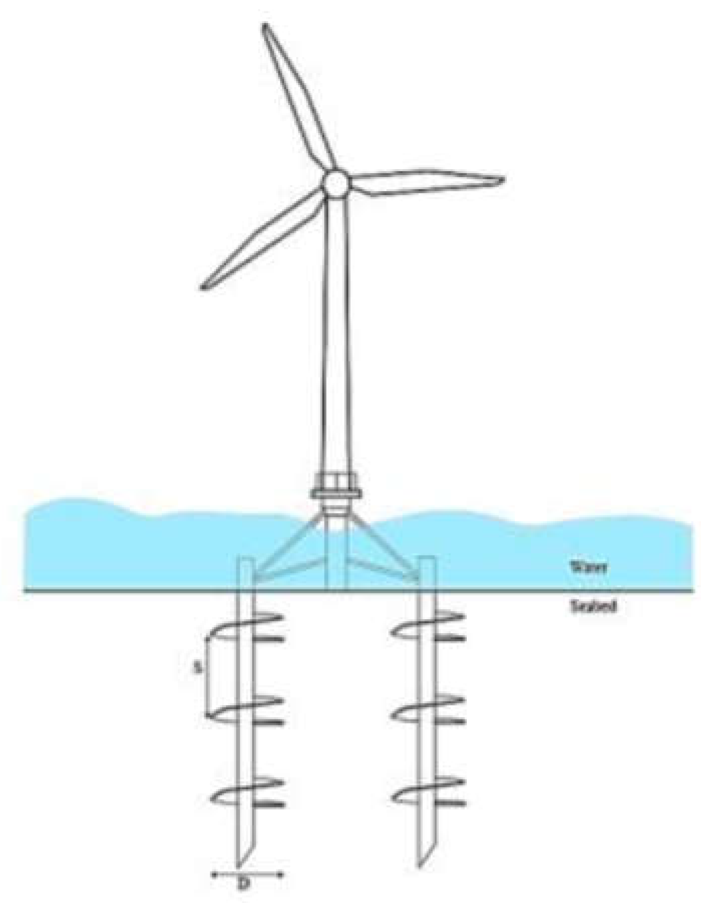
The diverse practical projects discussed above show that helical piles can be successfully used in construction of new buildings, rehabilitation of old buildings, retrofitting of bridges and etc. The confidence of contactors and people increases as the number of successful projects increases. Helical piles can also be used as a foundation in solar farms, billboards and transmission towers. Moreover, the application of helical piles in the design of offshore wind turbine can revolutionize the green technology in upcoming years [47]. Some researchers have recently been working on the applicability of helical piles for offshore wind turbines. According to the centrifuge modelling test results conducted by Ullah [47], helical piles can resist significant uplift and lateral forces if used in the foundation of offshore wind turbine. According to Ullah’s findings, in addition to rapid installation and cost effectiveness, helical piles pose no danger for marine life. Since its installation is vibration free, harmful acoustic emissions, which endanger marine life, are eliminated. shows schematic of helical piles used as foundation of offshore wind turbines.
Figure 6.
Schematic of helical piles used as foundation of offshore wind turbine [47].
Figure 6.
Schematic of helical piles used as foundation of offshore wind turbine [47].
2.3. Advantages of Helical Piles over Traditional Foundations
Helical piles offer a compelling solution for the logistical and productivity challenges of remote Australian transmission projects. Their installation process is significantly faster and more efficient than traditional methods, resulting in substantial savings in time, labor, and equipment [51].
2.3.1. Remote Constructability and Installation Process
The installation of helical piles is a low-impact process that requires minimal excavation and no soil removal, as the pile displaces the soil sideways as it screws into the ground [54]. This eliminates the need for large-scale digging and the associated costs and complexities of handling and disposing of soil spoils [55]. The process is also quiet and vibration-free, making it ideal for projects in both remote and environmentally sensitive areas and urban locations with limited access [56]. shows installation equipment of a helical pile.
Figure 7.
Installation equipment of a helical pile [57].
Figure 7.
Installation equipment of a helical pile [57].
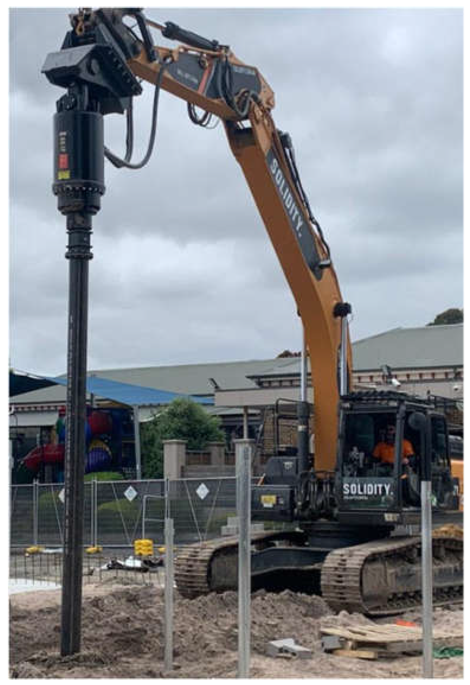
The installation equipment is typically a hydraulic drive head mounted on common construction machinery, such as an excavator or skid steer [58]. This use of readily available, often smaller equipment simplifies site access and reduces the logistical costs of mobilizing heavy, specialized rigs to remote locations [54]. The installation process is not affected by weather conditions, a major advantage in Australia’s diverse climate, as piles can be installed in wet, dry, or mixed conditions without delays. Despite bored pile, which often stop with rain events due to soil handling and mud conditions and they require vast water usage, helical piles are totally independent to weather conditions and they need no water for installation [55].
A further constructability advantage of helical piles is the elimination of the curing-and-release hold point that is inherent to cast-in-place concrete foundations. In concrete practice, 28 days remains the standard reference age for specified compressive strength, while even conventional structural curing guidance commonly assumes at least 7 days of initial moist curing for ordinary structural concrete [59]. For bored pile and tower foundation works, this material behavior translates into a program constraint because erection and subsequent loading are typically governed by strength gain and release criteria rather than excavation completion alone. Peer-reviewed work on concrete piles likewise shows that the common assumption that piles are ready for integrity testing after 7 days is not universally reliable; Niederleithinger and Taffe reported that defect detection may be possible after a few days, but is more reliable after about 10 days, confirming that concrete foundations introduce a non-trivial waiting period even before the next activity can proceed [60]. In transmission-line practice, this sequencing is explicit: one overhead-line installation specification requires concrete tower foundations to be allowed to set for a minimum of 7 days before tower erection and 28 days before conductor and earth-wire installation, while a recent HumeLink construction update similarly notes that tower erection proceeds only after the concrete foundations have cured. Accordingly, the program benefit of helical piles is not merely zero curing time in a material sense; it is the removal of a foundation release constraint from the critical path. Some projects do permit earlier tower erection once sufficient in-place strength is demonstrated—for example, one transmission ESIA notes that concrete requires 28 days for total curing, but that tower erection could begin after about 8 days once roughly 80% of final mechanical resistance is achieved. This indicates that the exact delay is project-specific, but it also confirms that bored concrete foundations remain governed by a staged strength-verification process rather than immediate readiness. By contrast, field testing of helical piles in cohesive soil has shown that piles can be evaluated immediately after installation, and that installation-induced pore-pressure effects had little influence on short-term ultimate capacity, supporting the practical observation that helical piles can transition directly to the next construction stage without a curing hold point [61,62,63,64]. For transmission towers, the resulting schedule benefit can therefore be reasonably expressed as up to 28–35 days removed from the critical path, particularly when the full release sequence is considered, including curing, strength verification, inspection sign-off, and readiness for tower erection and subsequent stringing activities.
The consequence of this time saving is also material. Pile-construction research has shown that cycle time, productivity, and cost are tightly coupled, and that pile works should be analyzed as a combined time–cost process rather than as a purely material quantity problem [65,66]. In practical EPC terms, removing a 28–35-day foundation release window reduces time-related preliminaries such as supervision, access-road maintenance, traffic management, equipment standby, remobilisation risk, and exposure to rain or groundwater-related delays at partially completed sites. Rather than assigning a universal dollar value without project-specific cost data, the paper can state this more rigorously as: for a tower site with daily indirect cost C_day , the avoided time-related cost is approximately
with the additional benefit that tower erection can be sequenced in a more continuous install-and-progress workflow. That framing is academically safer than asserting a fixed saving per foundation, while still making clear that the absence of curing is both a schedule and a commercial advantage [65,66].
2.3.2. Productivity Metrics
The productivity of helical pile installation is a key differentiator. A small crew of one to two people per rig can be used [58]. Industry data suggests that a crew can install up to 20 piles in a single day [51], with some project case studies reporting rates as high as 40 to 50 piles per day [67]. This speed reduces project timelines, with foundations for large projects often completed in a matter of weeks, in stark contrast to the months-long process required for traditional methods [68].
This efficiency is further amplified by the absence of curing time, which removes up to 28–35 days from the critical path. Moreover, repeatable prefabrication (factory-first philosophy) also accelerates the on-site installation process. Once installed, helical piles have immediate load-bearing capacity, allowing the next construction phase, such as tower erection, to begin immediately [55]. This directly reduces project delays and allows for a more streamlined, just-in-time construction workflow [67].
2.3.3. Quality Assurance and Quality Control (QA/QC)
The QA/QC process for helical piles is a critical advantage. Unlike traditional deep foundations, which rely on geotechnical reports that can only provide an estimated capacity, helical pile capacity can be verified in real-time during installation [9]. The most widely used method for on-site verification is the torque correlation method, which relies on the empirical relationship between the ultimate pile capacity (Qu) and the final installation torque (T) [69]. This is expressed by the formula Qu=Kt×T, where Kt is an empirically derived torque correlation factor [69]. This provides a continuous, real-time readout of soil strength and pile capacity during installation, allowing the operator to verify that the required capacity has been achieved [69].
For critical projects, Australian Standard AS 2159 mandates that on-site load testing, considered the gold standard, be performed to provide definitive proof of the pile's performance [69]. This two-tiered approach to quality control provides a high level of confidence that the as-built foundation meets the engineering design requirements. The supervising engineer plays a key role in reviewing detailed installation logs that document the final depth and torque of each pile, ensuring compliance with Australian standards and the design plan [69].
The productivity and QA/QC advantages of helical piles represent a strategic risk mitigation strategy for large-scale, remote projects. In a market facing significant workforce and logistical challenges, a foundation system that requires less manpower, less specialized equipment, and less material transport directly reduces project risk and cost exposure.
2.4. Design and Performance of Helical Piles
The performance and the durability of helical piles is a critical factor for long-term infrastructure projects and depend on so many factors including soil stiffness, soil moisture, the material of helical piles, pile geometry and pile head fixity [70]. Helical piles are manufactured from high-grade steel, such as C350 grade or ASTM A500 Grade C, and are protected from corrosion, typically through hot-dip galvanization [32]. Studies on steel piles with decades of service show that the corrosion rate is negligible for the majority of the pile, as it is embedded in undisturbed, oxygen-deficient soil [50]. Protection is most critical for the portion of the shaft near the ground line, where increased oxygen availability poses a higher risk of corrosion. Hot-dip galvanization or epoxy coatings are commonly used to mitigate this risk [50]. With proper protection, the service life of a helical pile can exceed 100 years, making it a reliable choice for long-term infrastructure projects [8]. There is also a feasibility to substitute sacrificial thickness with coatings for 100-year design life [Brodie to specify reference for this statement].
AS2159-2009 (Australian Standard for Piling Design and Installation) provide a structured, risk-based framework for determining the appropriate level of corrosion protection for steel piles, including helical piles. Their purpose is to guide engineers in selecting a protection method that matches the aggressiveness of the site environment, ensuring the pile's long-term durability [71].
Tables 6.5.2(A) and 6.5.2(B) define the site's corrosive aggressiveness. These tables are used together to classify the site environment. Think of it as a corrosion risk score for the ground. Once the site's aggressiveness class is determined from the tables above, table 6.5.3 can be used to find the required protection. For each aggressiveness class (negligible to very high), it lists acceptable methods, which generally involve a combination of: steel thickness, protective coatings, and cathodic protection [71].
Among factors effecting the durability of helical piles, design process has the highest impact on improvement of helical piles performance and can be manipulated via engineering, while the properties of soil cannot be changed and is totally dependent on project site [70].
The performance of a helical pile is highly dependent on its geometry. Industry standards dictate a uniform pitch for the helices, typically 3 inches per 360-degree rotation [50]. This ensures that each helix tracks through the same continuous helical groove cut into the soil, minimizing disturbance and preserving soil strength [50]. This is in contrast to piles with a variant geometry that behave more like an auger, which can cause significant soil disturbance and compromise the pile's ultimate capacity [56]. The helical plates are arranged on the shaft such that their diameters either remain the same or increase as they get farther from the pilot point, ensuring efficient advancement [50]. However, a study by Mamdouh Nasr et.al. proves that even helical piles may suffer soil loosening problems. This study argues that the common way helical piles are designed is flawed because it only focuses on whether the pile can hold the ultimate load without breaking. It ignores the critical issue of how much the pile will settle under normal, everyday loads. The author used a real-world case study of a helical pile installed in very dense sand. The installation required extremely high torque, which stirred-up and loosened the dense sand around the pile (a process known as dilation). When the pile was load-tested, it had enough ultimate strength, but it performed poorly under its intended working load. It settled (moved downward) much more than expected because the loosened sand particles were re-compacting under the load [72].
The study concluded that even though standard design formulas correctly predicted the pile's ultimate failure load but completely failed to predict the large and problematic settlement at normal service loads. The high-force installation process permanently alters the soil around the pile, and this must be considered in the design. Ignoring this leads to poor performance. To predict settlement and account for complex soil behavior (like dilation in dense sand), engineers should use advanced tools like Finite Element Modeling instead of relying solely on simple, outdated formulas [72]. There are some other factors that should be considered while designing a helical pile.
2.4.1. Fatigue & Dynamic Load Considerations
A critical design concern about helical piles is that these piles frequently experience cyclic loading, which can progressively degrade their capacity and lead to failure. Therefore, understanding their tensile performance under repeated loading is essential.
Cyclic loading on foundations can be classified by its direction—unidirectional (in either compression or tension) or bi-directional (alternating between the two)—and by its rate of application. Loads are categorized as static, quasi-static, or dynamic. Quasi-static cycles occur at low frequencies where inertial forces are negligible, while dynamic cycles involve significant inertial forces, with a threshold often set at 5 Hz. Experimental methods to assess cyclic effects typically involve applying controlled sequences of loading and unloading at set frequencies and amplitudes. The pile's response is governed by the interplay between the average load (Qavg) and the cyclic amplitude (Qcyc), determining whether the system remains in a stable, metastable, or unstable state. Notably, when maintained within a stable regime, low-frequency cycling can enhance load capacity, with some studies reporting capacity increases of up to 20% following controlled cyclic loading. Performance under repeated loading is essential. So many researchers have tried to understand the relationship between cyclic loading and helical pile performance. For example, Cerato and Victor determined that the repeated application of cyclic loads can enhance a helical pile's ultimate tensile capacity while also mitigating long-term creep. They attribute this improvement to progressive soil densification directly above the helical plate, a mechanism activated by the repetitive loading process. Beyond capacity considerations, cyclic tensile loading induces a repetitive uplift motion that can generate voids beneath the helical plate. Schiavon noted that these voids are particularly pronounced under conditions of high cyclic load amplitude or in low-density soil zones. Complementing this, Costa demonstrated that greater load amplitudes and higher mean loads diminish both the stability and the overall stiffness of the pile-soil system. Although helical piles are seeing growing application in foundation engineering, a significant research gap persists regarding their behavior, most notably their performance under cyclic loading. Thus, more precise investigation and modeling techniques are required to evaluate helical piles performance under cyclic loading [73].
2.4.2. Lateral Capacity Behavior of Helical Piles and
The lateral capacity of a helical pile refers to its ability to resist horizontal loads (e.g., from wind, seismic activity, earth pressure, or machinery) applied perpendicular to its shaft. Unlike tension and compression, which are resisted primarily by the helices, lateral load is resisted almost entirely by the passive pressure of the soil acting against the embedded shaft and helices. In essence, the lateral capacity behavior of a helical pile is governed by the bending resistance of its shaft and the strength/stiffness of the surrounding soil. While the helices are critical for axial loads, they play a secondary role in lateral resistance. Design, therefore, shifts focus from helix configuration to shaft geometry and soil-structure interaction analysis to ensure the pile can resist horizontal forces without excessive deflection or structural failure [74].
Among the factors controlling lateral capacity, the geometric and material properties of the shaft itself are dominant. The shaft diameter is paramount, with lateral capacity scaling roughly with the cube of the diameter in each soil, due to the concurrent increase in bending stiffness (EI) and the surface area for soil passive pressure. Furthermore, the wall thickness and material grade define the structural limits, safeguarding against yielding or buckling. Although circular cross-sections are standard, square shafts present a design alternative, offering enhanced bending stiffness per unit weight for more efficient lateral resistance [74].
The lateral capacity of a helical pile is critically dependent on the soil profile and its geotechnical properties. The stiffness and strength of the surrounding soil are fundamental, with dense sands and stiff clays offering a significantly higher modulus of subgrade reaction and thus greater lateral resistance compared to lose sand or soft clays. The depth to the first helix also plays a key role, as this uppermost plate acts as a rotational restraint or bearing node; a deeper first helix results in a longer unrestrained length of shaft above it, generally diminishing lateral capacity [74].
Several design strategies can significantly enhance the lateral capacity of helical piles. The most effective single measure is increasing the shaft diameter, which substantially boosts bending stiffness and the frontal area for soil passive pressure; using a thicker-walled pipe also improves structural capacity. For projects with substantial horizontal forces, installing piles on a batter (an incline) is a highly effective technique, as it converts lateral loads into more efficiently resisted axial loads within the pile group—placing one pile in tension and another in compression. At the connection point, designing a moment-resisting (fixed-head) connection at the pile cap, as opposed to a pinned connection, restrains rotation and can markedly increase capacity while reducing deflection. Finally, in weak or loose soils, post-installation grouting around the shaft can be employed to effectively increase the pile's diameter and the stiffness of the surrounding soil matrix, resulting in a dramatic improvement in lateral performance [74].
Even with battered piles, fixed-head connections, and large-diameter shafts, there is a practical economic and geometric limit to the lateral capacity of a single helical pile or a small group. For structures imposing exceptionally high lateral shear or overturning moments—such as tall signboards, cantilevered retaining walls, large bridge abutments, or the legs of heavy industrial equipment, the required shaft diameter or batter angle may become impractical. In these cases, a reinforced concrete pile cap integrated with ground beams or a structural grillage is essential to distribute the massive lateral loads across multiple piles and engage deeper, more competent soil layers for passive resistance [75].
2.5. Installation Failure Modes of Helical Piles and Mitigation Strategies
Based on current guidelines and technical knowledge, the main installation failure modes for helical piles are premature refusal (inability to reach design depth), loss of pitch or auguring, and shaft buckling during installation. These issues almost always result from a mismatch between equipment, design, and site conditions. summarizes each failure mode's causes, consequences, and key mitigation strategies.
Table 3.
Failure mode's causes, consequences, and key mitigation strategies of helical piles [76,77].
| Failure mode | Primary causes | Consequence if unchecked | Key mitigation strategies |
|---|---|---|---|
| Premature refusal | Obstructions (rock, debris), denser-than-expected soil (e.g., hard till), undersized installation equipment. | Pile fails to reach load-bearing stratum, resulting in inadequate capacity. | Use larger, more capable equipment (e.g., excavator over skid-steer); Perform pre-installation site investigation; Pre-drill through obstructions. |
| Loss of pitch/augering | Insufficient downward axial force from equipment; High-torque, low-penetration installation. | Soil is excessively disturbed, torque-to-capacity correlation is invalid, leading to reduced capacity. | Use equipment with adequate breakout force & weight; Monitor rate of penetration (aim for 2.5-3 inches per revolution). |
| Shaft buckling (during installation) | Installing in very soft/loose soils with slender square shafts; Lack of lateral soil support. | Structural damage to the pile, making it unfit for service. | Switch shaft type: use pipe shafts, combo piles, or grouted micropiles in soft soils. |
2.6. Practical Deployment Limits of Helical Piles
Based on standard engineering practice, helical piles can be an excellent foundation solution, but there are specific, challenging ground conditions where their use is generally unsuitable or requires extreme caution. These conditions often make installation impractical, uneconomical, or result in insufficient capacity. Helical piles are fundamentally unsuitable for sites where competent bedrock is found within one meter of the surface, as the system cannot achieve the necessary embedment for stability. They are also ill-advised in dense, abrasive soils like river gravels, where high installation torque leads to premature refusal and equipment damage. Furthermore, sites with obstructions such as boulders pose a high risk, causing piles to deflect off-course and creating unpredictable foundation results. Honest engineering guidance dictates avoiding helical piles in these first two scenarios, as alternative systems like driven piles, drilled caissons, or spread footings are more reliable and economical. For sites with potential obstructions, their use requires thorough pre-investigation and a clear contingency plan to manage the significant installation risks [78].
2.7. Grouped Pile Performance for Tower Legs
Transmission towers, which require a foundation system capable of resisting significant compressive, tensile, and lateral loads, often utilize a group of piles at each leg [30]. The behavior of closely spaced pile groups is a critical design consideration, as the interaction between adjacent piles can reduce their overall performance. However, research indicates that the unique geometry of helical piles fundamentally alters pile group mechanics, resulting in more predictable and often superior performance compared to conventional pile groups [49].
Studies have shown that helical pile groups exhibit less group interaction and a lower reduction in group performance compared to conventional pile groups at equal spacing [49]. This is primarily due to the helical pile's slender shaft diameter, which is significantly smaller than its helix diameter [49]. This geometry localizes soil displacement around the helices and reduces the stress and strain fields between adjacent piles, minimizing shaft-to-shaft interaction [49]. The failure mode for helical pile groups is typically individual bearing failure of each pile, rather than the less efficient block failure that can occur with closely spaced conventional piles [79]. This means that for a given load requirement, a helical pile group may require fewer piles or smaller spacing, which has direct cost and time implications for a project.
The typical group spacing rule of maintaining a center-to-center distance of at least three times the largest helix diameter (≥3D) between adjacent helical piles is a fundamental guideline to ensure optimal group efficiency. This spacing prevents the overlapping of individual pile stress bulbs—the zones of soil that are stressed and mobilized to provide bearing capacity. If piles are spaced too closely, their stress bulbs interact and merge, effectively forcing the group to behave as a single, larger foundation block that bears on a deeper, weaker soil layer, significantly reducing the collective capacity of the individual piles. By adhering to the 3D rule, each pile is guaranteed to mobilize its own distinct, undisturbed volume of soil, allowing the designer to simply sum the capacities of each pile to calculate the total group capacity without a reduction factor. This principle is critical for foundations supporting heavy structures like transmission towers, where closely-spaced piles would otherwise suffer from diminished efficiency and potential excessive settlement due to this detrimental group interaction [80].
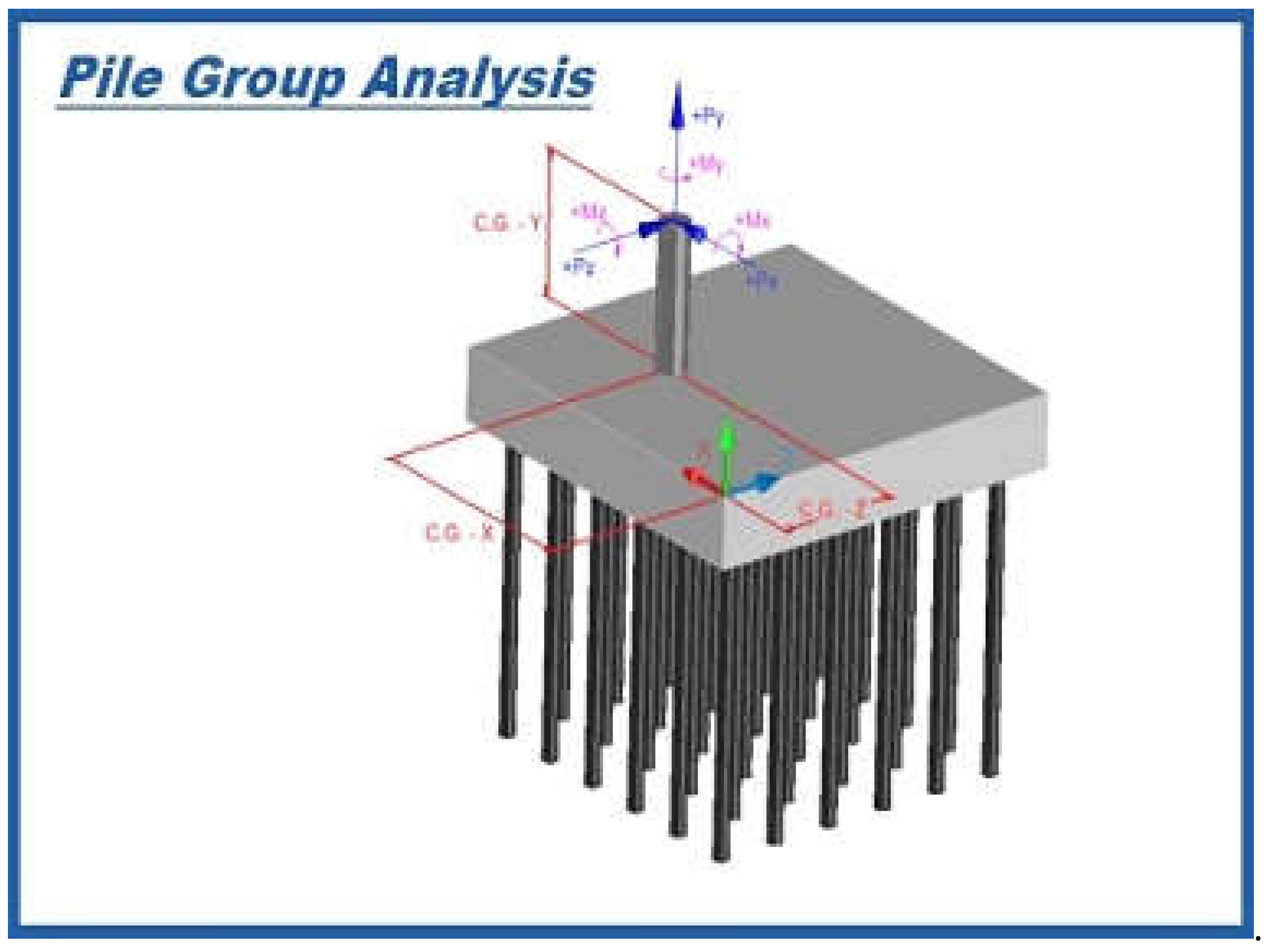
Research also indicates that while the effects of installation-induced excess pore pressure significantly reduce the performance of groups in cohesive soils, these effects are limited to the soil near the pile shaft for single piles and do not affect their ultimate state capacity [79]. shows grouped helical piles [81].
Installing helical piles at a raked (battered) angle is a structurally superior solution for handling the eccentric loads from diagonal tower legs. The core advantage lies in aligning the pile's axis directly with the dominant force path from the leg, transforming the problematic horizontal load component into a more efficient axial load along the pile. This approach utilizes the helical pile's greatest strength—its ability to resist high tension or compression through helix bearing—while virtually eliminating the bending moments and reliance on weaker lateral soil resistance that plague vertical piles under the same eccentric conditions. By matching the rake to the leg geometry, the foundation system directly and efficiently resolves the overturning forces, leading to a more stable, reliable, and often more economical design [80].
Figure 8.
Grouped helical piles [81].
Figure 8.
Grouped helical piles [81].
3. Case Snapshots and Comparative Metrics
While traditional methods like bored concrete piles have historically been the default for major transmission projects, recent Australian case studies in the renewable energy sector demonstrate the clear advantages of helical piles.
3.1. The Limondale BESS Case Study
A prime example is the Limondale BESS (Battery energy storage system) project in New South Wales, Australia, which serves as a powerful case study for the successful application of helical piles in a large-scale energy infrastructure project [67]. The project required the installation of foundations for 144 lithium-ion batteries, with each unit requiring six helical piles, for a total of 864 piles [67].
The foundation was designed to withstand a range of structural stresses, including compression, tension, and lateral forces [67]. The lengths and helix configurations were determined through geotechnical analysis to ensure maximum load-bearing capacity while maintaining installation efficiency [67]. The piles were fabricated with a 139.7 mm shaft diameter and utilized high-grade steel [67].The project was subject to tight timeframes, with a 60-day deadline to complete the foundation works [67].
By leveraging a streamlined manufacturing and installation workflow, including a just-in-time fabrication model, the installation team was able to achieve a remarkable productivity rate of 45-50 piles per day [67]. The project was completed on time, within budget, and with zero safety incidents, demonstrating the efficiency and reliability of helical piles for large-scale energy projects.
The Limondale BESS case is most useful when distinguished between the overall project program and the specific piling work package. Public project information indicates that construction of Limondale BESS commenced in late 2024, with overall completion targeted for December 2025, while the civil contractor reported completion of its package in March 2025 [82,83]. Against that broader schedule, the manuscript case data indicate that the foundation scope comprised 864 helical piles for 144 battery units, to be delivered within a 60-day foundation window, with achieved installation productivity of 45–50 piles per day. On that basis, the minimum average productivity required to satisfy the nominal program was only 14.4 piles/day, whereas the reported achieved rate was approximately 3.1–3.5 times higher. If sustained across the full pile scope, the achieved rate corresponds to about 17.3–19.2 working days of pile installation. The principal program lesson is therefore not merely that the works were fast but that the piling methodology created meaningful schedule float within the foundation package, thereby improving resilience to survey hold points, cap construction, weather interruptions, inspections, and other interface constraints [82,83,84].
A second lesson concerns the interpretation of torque variance. Installation torque is not a nuisance variable; it is a primary field response governed by soil strength, embedment depth, helix geometry, shaft dimensions, and crowd force, and recent studies show that torque–capacity correlations may be materially influenced by spatial variability in the ground [85,86,87]. At Limondale, any observed variation in installation torque between piles should therefore be framed as expected geotechnical feedback across the site rather than as evidence of unreliability. In practical QA/QC terms, this reinforces the value of pile-by-pile digital logging and engineering review, because variability in torque can be used to confirm changing subsurface resistance and refine acceptance decisions in real time. That interpretation is consistent with the contractor’s public description of AS 2159-compliant digital logging, company-owned installation equipment, and in-house manufacturing, all of which support rapid operational response to variable field conditions [84,85,86,87].
The third lesson is logistical. Construction research shows that pile-installation productivity depends strongly on the synchronisation of off-site fabrication, transport, and field crews, and that poor sequencing measurably reduces process efficiency [88,89]. The Limondale case is consistent with this literature: the reported just-in-time /factory-first workflow appears to have converted fabrication control and short-haul logistics into field productivity, thereby reducing idle time and mobilisation inefficiency. Environmental considerations should also be noted. At project level, Limondale BESS connects via the existing 33 kV substation, reducing the need for new infrastructure and associated disturbance, while helical-pile literature identifies rapid installation with low vibration and noise as an intrinsic advantage over more intrusive deep-foundation methods [90,91]. For the paper, this is best stated conservatively as a reduction in ground disturbance, wet-concrete dependency, and site-interface complexity relative to bored foundations, rather than as an absolute claim of zero environmental impact [88,89,90,91].
3.2. Xcel Energy Rebuilt
Xcel Energy rebuilt a critical 2.7-mile, 69-kV transmission line crossing the Upper Mississippi River National Wildlife and Fish Refuge near Nelson, Wisconsin. The line, originally built in 1934 with wooden H-frames, had outlived its life expectancy, with many foundations submerged in backwater. The rebuild aimed to ensure long-term reliability while minimizing environmental impact in this sensitive federal refuge. The Xcel Energy transmission line rebuild successfully navigated a complex set of environmental and logistical constraints through a series of targeted engineering solutions. To protect the sensitive wetlands of a federal wildlife refuge, the team utilized helical pile and grillage foundations, installed with specialized marsh equipment to minimize ground disturbance. An extremely tight two-week outage window was met by pre-installing these foundations and then employing heavy-lift helicopters to erect structures and string conductors. The very soft, poor soil conditions encountered were addressed by advancing the helical piles to depths of 40-90 feet to reach competent bearing strata. For the four structures in open water, where ice forces were a concern, the design shifted to large-diameter steel caissons. Finally, a multi-layered corrosion protection system—combining sacrificial steel, galvanizing, and coatings—was implemented to ensure the longevity of all foundations in the fluctuating aquatic environment, resulting in a project completed ahead of schedule [92].
4. Comparative Metrics for Foundation Selection
The case of Limondale BESS, as well as industry-wide data, provides a clear contrast to traditional methods like the bored Piles used for projects such as the Project EnergyConnect interconnector in NSW, SA, and Victoria [93]. The decision to use bored Piles on EnergyConnect was based on their ability to handle heavy structural loads and their suitability for good ground conditions, but they require significant on-site resources, including large-scale excavation, cranes, and concrete pumps, which can lead to longer project timelines and higher costs [93].
provides a data-driven comparison of helical piles versus bored piles, summarizing the key differences in performance, logistics, and explains cost-benefit and comparison of installation and cost-benefits of helical and bored piles.
Table 4.
Comparison of geotechnical and structural performance of helical and bored piles.
| Geotechnical and structural performance | Helical pile | Bored pile |
|---|---|---|
| Load capacity | High capacity (up to 2400 kN per pile); verifiable through installation torque correlation or load testing [55]. | High capacity (up to 13,800 kN per pile); capacity is estimated and verified through post-installation testing [94]. |
| Group efficiency / Interaction | Lower group interaction; piles fail individually rather than as a block [49]. | Higher group interaction; risk of block failure in closely spaced groups [49]. |
| Suitability for challenging soils | Excellent; bypasses unstable layers to anchor in deep, stable strata or bedrock [32]. | Can be problematic; susceptible to heave/shrink in reactive clays and collapse in sandy or waterlogged soils [29].. |
| Quality control (QC) | Real-time capacity verification via torque correlation for every pile installed [69]. | Capacity is estimated based on soil bore data; post-installation testing is required for verification [9]. |
Table 5.
Comparison of installation and cost-benefits of helical and bored piles.
| Installation and cost-benefit | Helical pile | Bored pile |
|---|---|---|
| Installation Time / Productivity | Very rapid; up to 40-50 piles/day on large projects [51]. | Slow; multi-day process per footing, with on-site drilling and concrete work [93]. |
| Crew Size | Small; 1-2 person crew per rig [58]. | Large; requires specialized drilling, crane, and concrete teams [93]. |
| Site Disturbance | Minimal; no excavation, no spoils, and no vibration [50]. | Extensive; requires excavation and management of soil spoils [9]. |
| Cure Time | Zero; immediate load-bearing capacity allows for instant construction [54]. | Significant; concrete requires up to 4 weeks to reach full strength [54]. |
| Environmental Footprint | Lower embodied carbon (steel is recyclable); reduced water usage; minimal impact on soil and landscape [8]. | High embodied carbon (concrete production is a major CO2 source); requires large amounts of water for curing; disrupts natural landscape [8]. |
In addition to geotechnical performance and installation cost, foundation selection should also be evaluated in terms of delivery-risk exposure. compares the principal project-risk pathways associated with helical piles and bored piles. The classifications are comparative interpretations of the published literature rather than absolute rules, and actual exposure remains dependent on investigation quality, contractor capability, and the project procurement model.
Table 6.
Comparison of Risk Profile Differences Between Helical and Bored Piles.
| Risk profile difference | Helical pile | Bored pile |
|---|---|---|
| Latent Conditions | Lower residual in-ground uncertainty after installation. Each pile generates installation torque and depth records, so part of the subsurface uncertainty is converted into measurable field data during construction. However, risk is not eliminated: torque–capacity correlation can still be mis-estimated if spatial variability is not properly accounted for [21,95]. | Higher residual latent-conditions exposure. Capacity and integrity remain more dependent on sampled geotechnical investigation and post-installation inspection. Published bored-pile defect literature shows that only a limited proportion of piles may be inspected in practice, and defects can lead to remedial work, disputes, delay, and added cost [21,96]. |
| Weather delays | Lower weather sensitivity at the workface. Helical piles avoid wet-concrete curing and shift more activity into prefabrication and mechanical installation, reducing dependence on weather-sensitive site operations. Off-site construction literature also notes lower weather dependence at site when work is transferred to fabrication shops [97,98,99]. | Higher weather sensitivity. concrete-task productivity is materially affected by precipitation, wind, and temperature, and adverse curing conditions can reduce concrete stiffness and strength. This creates a more weather-exposed construction sequence for bored foundations [97,100,101]. |
| Supply Chain | Moderate but more centralised supply-chain risk. Risk is concentrated in steel fabrication capacity, transport sequencing, and supplier coordination. When managed well, prefabrication can reduce duration and improve cost control, but off-site construction literature still identifies constraints related to factory capacity, transport, and knowledge integration [98,99]. | Higher and more diffuse site supply-chain dependence. Delivery depends on drilling plant, reinforcement cages, concrete supply, and often casing/slurry systems and spoil handling. Pile productivity and cost are also sensitive to site planning and equipment maintainability [102] , [103]. |
| Workforce | Lower on-site labour exposure. A greater share of work is shifted from the site to controlled fabrication, which can reduce on-site labour demand, shorten project duration, and reduce labour wastage, although skilled operators and QA review are still required [99,102]. | Higher workforce exposure. Productivity depends on contractor experience, equipment maintainability, and coordination across multiple field crews and interfaces. This makes bored-pile execution more sensitive to labour availability and field-management quality [102] , [103]. |
The comparison in indicates that the principal advantage of helical piles is not only faster installation, but a reduction in hidden-condition and interface risk during delivery. In particular, helical piles tend to reduce the project exposure associated with unobserved in-ground defects, weather-sensitive concrete operations, and multi-interface site logistics. By contrast, bored piles remain a technically capable solution, but their risk profile is generally more dependent on field execution quality, inspection sufficiency, and weather-resilient site management.
5. Environmental Aspects
Helical piles offer a number of key advantages over traditional concrete foundations, helping to reduce the overall environmental footprint and align with modern sustainability goals.
5.1. Ground Disturbance
Helical piles are a type of displacement pile, meaning they are screwed into the ground with minimal soil disturbance [9]. This is a key advantage over concrete drilled shafts or bored piles. The minimal disturbance process preserves the natural stratification and integrity of the soil, which is crucial for local ecosystems and reduces the risk of erosion and runoff [104].This low-impact approach is particularly beneficial for projects that traverse environmentally sensitive areas.
5.2. Embodied Carbon and Recyclability
By eliminating or significantly reducing the need for large concrete footings, helical piles offer a lower-carbon alternative for foundations [8].This is further enhanced by the fact that the piles are made from steel, which is a highly durable and nearly infinitely recyclable material [8]. At the end of a structure's life, helical piles can be removed and either reused for another project or recycled, which supports a circular economy and significantly reduces waste [56].
The environmental benefits of helical piles are not merely a sustainability add-on; they are a core business case consideration. The AEMO's 2024 ISP includes a specific appendix on social licence [105], acknowledging the importance of community acceptance for project success. Community opposition and environmental concerns can cause significant project delays and cost overruns. By adopting a foundation system that minimizes ground disturbance, noise, and carbon emissions, transmission providers can build trust and acceptance, thereby de-risking the project timeline and budget [106].
6. Life-Cycle Cost Analysis
A technically robust comparison between helical piles and bored piles should not end at initial construction cost; it should instead be framed as a whole-of-life economic assessment. Recent transmission-line life-cycle cost studies define total life-cycle cost as the combined present value of initial investment, operation and maintenance, periodic maintenance, failure/remedial costs, and end-of-life disposal, with any salvage value credited against disposal cost [107]. This broader framing is especially relevant for tower foundations because communication-tower life-cycle cost research shows that long-term project economics are affected not only by material quantities, but also by policy standards, management capability, environmental constraints, procurement errors, design deviations, construction delays, and operational failure [108]. Accordingly, the economic comparison between helical and bored foundations should be expressed as a discounted cash-flow problem rather than a simple first-cost comparison.
A simple net present value (NPV) formulation for a foundation alternative may be written as:
where is the initial installed cost, is the inspection cost in year , is the maintenance cost, is the expected cost of defect remediation or failure-related intervention, is the end-of-life removal/disposal cost, is residual or salvage value, is the discount rate, and is the adopted design life.
Engineering life-cycle cost studies further show that discounted outcomes are highly sensitive to the choice of discount rate and to the treatment of future inspection, maintenance, and demolition costs; for that reason, a sensitivity analysis should be reported rather than a single-point result [109]. A practical presentation for this paper would be to evaluate the model at r=2%,3%,and 5%and report whether the ranking between helical and bored foundations changes across that range [109].
For transmission applications, the initial-cost term should be disaggregated to reflect the actual work package rather than just pile material quantities. For bored piles, the relevant first-cost components typically include drilling, reinforcement, concrete supply, spoil handling, curing-related preliminaries, and the plant fleet needed to support those operations. In contrast, recent Australian comparative life-cycle analysis of screw piles and bored piles reports that screw-pile installation is operationally simpler and that bored-pile construction requires additional equipment such as concrete truck mixers, loaders, and tipper trucks, with further dewatering requirements arising under rainy conditions [110]. This is consistent with prior pile-construction productivity research showing that pile cost is strongly influenced by site planning, equipment maintainability, and subsurface uncertainty, rather than by material quantities alone [102]. For transmission projects in remote or access-constrained corridors, these indirect and logistics-related terms can therefore materially affect NPV and should be included explicitly in .
The distinction between the two systems becomes even clearer when future cost streams are considered. Routine maintenance may be modest for both alternatives under normal inland exposure, but it should not be assumed to be zero. Life-cycle cost research on pile-supported infrastructure demonstrates that aging, corrosion, and damage accumulation can materially increase long-term cost; in one pile-supported wharf study, corrosion increased structural life-cycle cost by about 15% and total system life-cycle cost by about 8% [111]. Although that study concerns a harsher marine environment than an inland transmission corridor, it confirms the methodological point that future inspection, maintenance, and failure-related costs should be retained in the model. In practical terms, bored piles are more exposed to uncertainty associated with hidden defects and remedial intervention, whereas helical piles benefit from a more direct installation record through torque and depth logging; therefore, the expected remedial-cost term can reasonably be expected to be lower for helical piles where installation QA/QC is robust. That final inference should be presented cautiously as a project-risk judgment rather than a universal rule.
The end-of-life term is also relevant. A recent Australian cradle-to-grave comparison between screw piles and bored piles found that screw piles have a simpler deconstruction process, generate much lighter waste, and, for the average case studied, exhibit 85% lower end-of-life GWP and 84% lower end-of-life energy consumption than bored piles; the same study notes that screw piles can be fully recycled, whereas bored-pile demolition is more waste-intensive [110]. While those results are environmental rather than monetary, they support the economic direction of the NPV model: screw piles should generally carry a lower decommissioning burden and may justifiably be assigned a non-zero salvage term where recovery of steel is feasible. On this basis, the decision criterion becomes straightforward: the preferred alternative is the one with the lower discounted whole-of-life cost, not necessarily the lower first cost. For remote transmission projects, helical piles are likely to show a lower NPV when savings in logistics, preliminaries, delay exposure, and end-of-life burden are captured explicitly; however, the magnitude of that advantage remains project-specific and should be tested using the local soil profile, pile geometry, corrosion design, and supply-chain assumptions [107,109,110]. show input terms for simple NPV comparison of helical and bored tower foundations.
Table 7.
Input terms for simple NPV comparison of helical and bored tower foundations.
| Term | Helical pile | Bored pile |
|---|---|---|
| initial cost | Steel pile supply, transport, installation rig, QA/QC logging, mobilisation | Drilling, reinforcement cage, concrete, spoil handling, curing-related preliminaries, larger support fleet |
| (C^{\mathrm{ins}}_t) | Periodic inspection / verification | Periodic inspection / verification |
| (C^{\mathrm{mnt}}_t) | Corrosion protection / local repair if required | Crack / durability / local repair if required |
| (C^{\mathrm{fail}}_t) | Expected remedial cost under defect / performance shortfall | Expected remedial cost under defect / performance shortfall |
| (C^{\mathrm{decom}}) | Removal / recycling / disposal | Demolition / waste haulage / disposal |
| (S) | Potential steel salvage value | Typically, low or negligible salvage value |
7. Recommendations for Codes and Practice
The design and installation of helical piles in Australia are governed by AS 2159 [69] which provides a robust, performance-based framework rather than prescriptive, technology-specific guidance. While this flexibility supports engineering innovation, the absence of standardized parameters such as soil-specific torque-to-capacity (K_t) factors and helix geometries can lead to significant design variability. Some examples are available internationally such as the International Building Code (IBC) in the United States [112]. The IBC, through its acceptance criteria (AC358), provides clear, pre-established guidelines and default capacity-to-torque (Kt) factors for specific pile geometries [113]. This level of detailed guidance provides greater certainty for engineers and code officials, encouraging broader adoption. Future regulatory considerations could benefit from investigating standardized material grades and corrosion protection protocols calibrated for 50, 75, and 100-year design lives. Furthermore, there is a clear need for national guidance regarding the behavior of helical pile groups, particularly for critical infrastructure like transmission towers. A scientific consensus is also required to establish codified lateral load methodologies that address the unique soil-structure interaction of slender-shaft foundations. Addressing these research gaps would provide the necessary technical rigor to facilitate more consistent adoption across the Australian construction industry. Consequently, refining these geomechanical requirements within the national framework would enhance the overall reliability and serviceability of helical piling systems.
8. Conclusion
In conclusion, this analysis confirms that steel helical pile groups offer a superior, more resilient, and logistically efficient foundation solution for Australia's unprecedented energy transmission expansion. By directly addressing the critical limitations of traditional bored piles—including susceptibility to reactive clay soils, lengthy concrete curing times, high labor demands, and large environmental footprints—helical piles provide a technically robust alternative that is faster to install, verifiable in real-time, and better suited to the workforce and supply chain constraints facing major projects. As Australia races to modernize its energy grid, the inherent advantages of helical pile technology position it not merely as an alternative, but as a strategically vital component for delivering sustainable and reliable infrastructure.
Institutional Review Board Statement
This research did not involve any human participants or animal subjects.
Informed Consent Statement
Because this study did not involve human participants, informed consent was not required.
Conflicts of Interest
On behalf of all authors, the corresponding author states that there is no conflict of interest.
References
- Yu, H.; Li, H.; Zhang, Z.-Q.; Zhang, G.-F.; Wang, D.-H.; Zheng, H.-D. Failure Patterns of Transmission Tower-Line System Caused by Landslide Events. Energies 2022, 15, 7155. [Google Scholar] [CrossRef]
- Shuman, N.M.; Khan, S.; Amini, F. Settlement based load capacity curve for single helix helical pile in c - ϕ soil. Soils Found. 2022, 63. [Google Scholar] [CrossRef]
- CEATI international. Guide for Transformation Line Foundations with Least Impact to the Eenvironment. Available online: https://www.cooperative.com/programs-services/bts/documents/reports/91002k_presentation.pdf.
- Santoso, H.; Hartono, J.; Andani, R.; Primaswari, G. The Influence of Concrete Age on the Accuracy of Pile Integrity Testing on Bored Piles Foundation. CIOP Publ. 2024, 1373, 012045. [Google Scholar] [CrossRef]
- Keller. Bored piles / drilled shafts. Available online: https://www.keller.com/expertise/techniques/bored-piles-drilled-shafts.
- Zayed, T.; Halpin, D. Simulation of bored pile construction. 2001 Winter Simulation Conference. Proceeding 2001 Winter Simul. Conf. (Cat. No. 01CH37304) 2001, vol. 2, 1495–1503. Available online: https://informs-sim.org/wsc01papers/205.PDF.
- Kumar, A.S.; Gopi, R.; Murali, K. Comparative studies on conventional concrete and self-curing concrete. Mater. Today Proc. 2021, 46, 8790–8794. [Google Scholar] [CrossRef]
- Elite Helical Solutions, “Are Helical Piles Environmentally Friendly?”. Available online: https://elitehelical.com/are-helical-piles-environmentally-friendly/.
- Products, E. C. Helical Piles vs Concrete Drilled Shafts: Which Is Better For Deep Foundations? Available online: https://earthcontactproducts.com/helical-piles-for-deep-foundations/.
- DCCEEW, “Rewiring the Nation.”. Available online: https://www.dcceew.gov.au/energy/renewable/rewiring-the-nation.
- Australian Energy Market Operator, 2023 Transmission Expansion Options Report Important notice. in AEMO. 2023, pp. 1–145. Available online: https://www.aemo.com.au/-/media/files/major-publications/isp/2023/2023-transmission-expansion-options-report.pdf.
- Australian Energy Market Operator, “AEMO ’ s 2024 Integrated System Plan,” 2024. Available online: https://www.aemo.com.au/-/media/files/major-publications/isp/2024/2024-integrated-system-plan-overview.pdf.
- MCDONNEL, B. Helical Piles Improve Cost, Schedule and Durability of Substantial Industrial Projects. Available online: https://info.burnsmcd.com/service-feature/helical-piles-improve-cost-schedule-and-durability-of-substantial-industrial-projects.
- A. E. R. (AER), “AER approves costs for North West Transmission Developments early works,” 2025. Available online: https://www.aer.gov.au/news/articles/communications/aer-approves-costs-north-west-transmission-dev.
- S. Australia, “Standards Australia updates AS 4000:2025 General Conditions of Contract,” 2025. Available online: https://www.standards.org.au/news/standards-australia-updates-as-4000-2025-general-conditions-of-contract (accessed on 25 Feb).
- West, V. “VNI West Project Update: July 2025,” 2025. Available online: https://vniwproject.com.au/project-updates/project-updates/vni-west-project-update-july-2025 (accessed on 25 Feb. 2026).
- M. L. P. Ltd. Project timeline. Available online: https://www.marinuslink.com.au/project-timeline/ (accessed on 25 Feb. 2026).
- N. Powerlink, “Geotechnical works to inform planning and design,” 2025. Available online: https://engage.powerlink.com.au/calvale-calliope-river-transmission-line-reinforcement-project/geotechnical-works-inform-planning-and-design (accessed on 25 F).
- Australia, “2025 Infrastructure Market Capacity Report,” 2025. Available online: https://www.infrastructureaustralia.gov.au/reports/2025-infrastructure-market-capacity-report (accessed on 25 Feb. 2026).
- Chwała, M.; Phoon, K.-K.; Uzielli, M.; Zhang, J.; Zhang, L.; Ching, J. Time capsule for geotechnical risk and reliability. Georisk Assess. Manag. Risk Eng. Syst. Geohazards 2022, 17, 439–466. [Google Scholar] [CrossRef]
- Spross, J.; Olsson, L.; Stille, H.; Hintze, S.; Båtelsson, O. Risk management procedure to understand and interpret the geotechnical context. Georisk Assess. Manag. Risk Eng. Syst. Geohazards 2021, 16, 235–250. [Google Scholar] [CrossRef]
- Hatem, D.J. Geotechnical baselines: Professional liability implications. Tunn. Undergr. Space Technol. 1998, 13, 143–150. [Google Scholar] [CrossRef]
- Ngoy, K.S.; Chisumbe, S.; Petere, G.; Mwiya, B.; Mwanaumo, E. Factors Influencing Professional Indemnity Insurance Use in Construction Risk Management. Balt. J. Real. Estate Econ. Constr. Manag. 2023, 11, 199–220. [Google Scholar] [CrossRef]
- Sakr, M. Relationship between Installation Torque and Axial Capacities of Helical Piles in Cohesive Soils. DFI J.-J. Deep. Found. Inst. 2013, 7, 44–58. [Google Scholar] [CrossRef]
- Li, D.; Tang, W.; Zhang, L. Updating occurrence probability and size of defect for bored piles. Struct. Saf. 2008, 30, 130–143. [Google Scholar] [CrossRef]
- Wikipedi. Geology of Australia. Available online: https://en.wikipedia.org/wiki/Geology_of_Australia.
- Loumain. Three basic Australian soil types. Available online: https://www.loumain.com/blog/3-basic-australian-soil-types-and-classifications.
- Delivering for Queensland, “Common soil types.”. Available online: https://www.qld.gov.au/environment/land/management/soil/soil-explained/types.
- Rogers, R. B. R. J. David; Olshansky, Robert B. “Damage to foundations from expansive soils,” 1993. Available online: https://www.residentialreports.com.au/wp-content/uploads/2022/03/Expansive-Clay-Soils.pdf.
- Versapile. Understanding Helical Piles for Communication Towers - VersaPile. Available online: https://versapile.com/blog/helical-piles-communication-towers.
- Pileblade. “Steel VS Concrete Blade Pile,” 2024. Available online: https://bladepile.com.au/wp-content/uploads/2024/04/BP_SvsC_Manual_2024-compressed_1.pdf.
- Helical Piles Australia, “When to Use Helical Piles.”. Available online: https://helicalpilesaustralia.com.au/when-to-use-helical-piles/.
- Hou, X.; Miao, X.; Yi, X.; Wang, Z.; Chen, Y.; Zhang, X.; Hui, B. Application of Bored Pile Technology Under Complex Geological Conditions. Mater. Strength Appl. Mech. Proc. 7th Int. Conf. (MSAM 2024), 2024; pp. 398–405. [Google Scholar] [CrossRef]
- Smith, R.E.; Anand, R.; Alley, N. Use and implications of paleoweathering surfaces in mineral exploration in Australia. Ore Geol. Rev. 2000, 16, 185–204. [Google Scholar] [CrossRef]
- George, R.J. Hydraulic properties of groundwater systems in the saprolite and sediments of the wheatbelt, Western Australia. J. Hydrol. 1992, 130, 251–278. [Google Scholar] [CrossRef]
- Anand, R. R.; Butt, C. R. M. “Distribution of ‘laterites’ and lateritic weathering profiles, Darling Range, Western Australia,” 2003. Available online: https://geomechanics.org.au/admin/wp-content/uploads/2015/03/38_4_4.pdf.
- Fityus, S.; Smith, D. The development of a residual soil profile from a mudstone in a temperate climate. Eng. Geol. 2004, 74, 39–56. [Google Scholar] [CrossRef]
- Rahardjo, H.; Satyanaga, A.; Leong, E.-C.; Ng, Y.S.; Pang, H.T.C. Variability of residual soil properties. Eng. Geol. 2012, 141-142, 124–140. [Google Scholar] [CrossRef]
- Li, D.; Tang, W.; Zhang, L. Updating occurrence probability and size of defect for bored piles. Struct. Saf. 2008, 30, 130–143. [Google Scholar] [CrossRef]
- Yao, H.; Ma, L.; Duan, Z.; Guo, W. Reliability analysis of the cast-in-place bored pile with different defects. Front. Built Environ. 2024, 10, 1337986. [Google Scholar] [CrossRef]
- Transgrid, “HomeLink.”. Available online: https://www.transgrid.com.au/projects-innovation/humelink/#:~:text=HumeLink.
- Transgrid, “Victoria to NSW Interconnector West.”. Available online: https://www.transgrid.com.au/projects-innovation/vni-west/.
- N. Government, “Victoria to NSW Interconnector West.”. Available online: https://www.planningportal.nsw.gov.au/major-projects/projects/victoria-nsw-interconnector-west?page=2.
- Marinuslink, “MarinusLink.”. Available online: https://marinuslink.com.au/.
- Energy, “energyandpublicworks.”. Available online: https://www.energyandpublicworks.qld.gov.au/projects-initiatives/queensland-renewable-energy-zones.
- Spagnoli, G.; Tsuha, C.d.H.C. A review on the behavior of helical piles as a potential offshore foundation system. Mar. Georesources Geotechnol. 2020, 38, 1013–1036. [Google Scholar] [CrossRef]
- Safdar, M.; Qureshi, H. A. Practical Applications of Helical Piles : A State-of- the-Art Literature Review. Univ. Eng. Technol. (UET) Taxila 2021, vol. 26(no. 4), 23–31. Available online: https://www.researchgate.net/publication/363265890_Practical_Applications_of_Helical_.
- By AlAn J. lutenegger, “Helical Screw Piles,” 2013. Available online: https://nfba.org/aws/NFBA/asset_manager/get_file/791808?ver=0.
- Lanyi-Bennett, S.A.; Deng, L. Axial load testing of helical pile groups in glaciolacustrine clay. Can. Geotech. J. 2019, 56, 187–197. [Google Scholar] [CrossRef]
- Watson, T. B. Fundamentals of Helical Anchors / Piles Part I. Available online: https://www.suncam.com/miva/downloads/docs/132.pdf.
- Mascore, “Revolutionize Your Foundation: The Complete Guide To Helical Piles.”. Available online: https://www.mascore.ca/mascore-blogs/guide-to-helical-piles.
- Bak, H.M.; Halabian, A.M.; Hashemolhosseini, H.; Rowshanzamir, M. Axial response and material efficiency of tapered helical piles. J. Rock Mech. Geotech. Eng. 2021, 13, 176–187. [Google Scholar] [CrossRef]
- Byrne, B.W.; Houlsby, G.T. Helical piles: an innovative foundation design option for offshore wind turbines. Philos. Trans. R. Soc. A Math. Phys. Eng. Sci. 2015, 373, 20140081. [Google Scholar] [CrossRef]
- FTA. Foundation Technologies Australia. Available online: https://www.foundationtechnologies.com.au/faqs/.
- Minmetals Australia, “Screw Piles - Minmetals Australia.”. Available online: https://minmetals.com.au/screw-piles/.
- Goliathtechpiles. Auger Piles vs Helical Piles: How to Choose? Available online: https://www.goliathtechpiles.com/auger-piles-vs-helical-piers-how-to-choose.
- Helical, Y.; Partner, P. PRODUCT REFERENCE CATALOGUE; 2025. [Google Scholar]
- Helicalpilesaustralia, “Reliable Deep Foundation Solutions.”. Available online: https://helicalpilesaustralia.com.au/.
- Ozer, B.; Ozkul, M. The influence of initial water curing on the strength development of ordinary portland and pozzolanic cement concretes. Cem. Concr. Res. 2004, 34, 13–18. [Google Scholar] [CrossRef]
- Niederleithinger, E.; Taffe, A. Early stage elastic wave velocity of concrete piles. Cem. Concr. Compos. 2006, 28, 317–320. [Google Scholar] [CrossRef]
- Oman, P. D. Specification for Installation of Overhead Transmission Lines, SP-1101, rev. 5.0, Aug. 2020. Available online: https://www.scribd.com/document/467023571/SP-1101-pdf.
- Transgrid, “HumeLink West Quarterly Newsletter,” 2025. Available online: https://www.transgrid.com.au/projects-innovation/humelink/newsletters/.
- Power, E. E. “ESIA—Jigjiga–Tog Wajaale 400 kV Double Circuit Transmission Line,” 2025. Available online: https://www.eep.com.et/wp-content/uploads/2025/02/1_ESIA-Jigjiga-Togo-Wajaale-High-Voltage-Transmission-Line.pdf.
- Lanyi-Bennett, S.A.; Deng, L. Effects of inter-helix spacing and short-term soil setup on the behaviour of axially loaded helical piles in cohesive soil. Soils Found. 2019, 59, 337–350. [Google Scholar] [CrossRef]
- Zayed, T.M.; Halpin, D.W. Pile Construction Productivity Assessment. J. Constr. Eng. Manag. 2005, 131, 705–714. [Google Scholar] [CrossRef]
- Zayed, T.M.; Halpin, D.W. Productivity and Cost Regression Models for Pile Construction. J. Constr. Eng. Manag. 2005, 131, 779–789. [Google Scholar] [CrossRef]
- Energy, “Strong foundations, stronger partnerships.”. Available online: https://www.energymagazine.com.au/strong-foundations-stronger-partnerships/.
- Helicalanchorsinc. Comprehensive Cost-Benefit Analysis: Helical Anchors vs. Traditional Foundation Methods. Available online: https://helicalanchorsinc.com/comprehensive-cost-benefit-analysis-helical-anchors-vs-traditional-foundation-methods/.
- Helicalpileaustralia, “The Engineer’s Guide to Helical Piles in Australia.”. Available online: https://helicalpilesaustralia.com.au/the-engineers-guide-to-helical-piles-in-australia/.
- Hussein, A.F.; El Naggar, M.H. Dynamic performance of driven and helical piles in cohesive soil. Acta Geotech. 2022, 18, 1543–1568. [Google Scholar] [CrossRef]
- A. Standards, “Piling-Design and Installation,” 2012. Available online: https://www.scribd.com/document/334696131/AS2159-Piling-Design-and-Installation.
- Nasr, M. Performance-Based Design for Helical Piles. In International Foundation Congress and Equipment Expo; 2009; Volume 2009, pp. 496–503. [Google Scholar] [CrossRef]
- Farias, M.L.A.; Costa, Y.D.J.; Queiroz, F.L.; Costa, J.P.d.S.; Macêdo, A.L.F. Influence of loading mode on the response of a helical pile subjected to cyclic tensile loads in sand. Soils Rocks 2025, 48. [Google Scholar] [CrossRef]
- Ahmad, H.; Ahmad, N.; Safdar, M. Parametric Study for Lateral Capacity of Helical Piles : A State-of-the-Art Literature Review. J. Appl. Emerg. Sci. 2021, no. 11, 228–234. [Google Scholar] [CrossRef]
- Murley, S.C.; Strom, C.M.; Herron, J.W. Alternate Foundation and Structure Designs: Mississippi Backwater Construction Challenges. In Electrical Transmission and Substation Structures 2022; American Society of Civil Engineers: Reston, VA, 2022; pp. 170–183. [Google Scholar] [CrossRef]
- S. E. Basics, “Helical Piles: An Emerging Two Century Old Deep Foundation Solution.”. Available online: https://structuralengineeringbasics.com/helical-piles/.
- Seider, P. E. G. L. How to Standardize the Installation of Helical Piles. Available online: https://helicalpileworld.com/standardize_helical_pile_installation.html.
- Huynh, D. V. K.; Tang, A. M.; Doan, D. H.; eds Watson, P. “Proceedings of the 2nd Vietnam Symposium on Advances in Offshore Engineering: Sustainable Energy and Marine Planning.,” Springer Nature. 2021. Available online: https://books.google.fr/books?hl=en&lr=&id=Qm5WEAAAQBAJ&oi=fnd&pg=PR5&dq=Limitations+of+Helical+Screw+Anchors.+In+Proceedings+of+the+2nd+Vietnam+Symposium+on+Advances+in+Offshore+Engineering:+Sustainable+Energy+and+Marine+Planning+(Vol.+208,+p.+310)&ots=Qhr8axOZ0s&sig=3nrHaMzQhCjN7VmpQBMI9aKX5SY&redir_esc=y#v=onepage&q&f=false.
- U. of Alberta. Behaviour of Helical Pile Groups and Individual Piles under Compressive Loading in a Cohesive Soil. Available online: https://ualberta.scholaris.ca/items/0c71f469-14c8-4981-a09e-e99b8c433329.
- Perko, H.A. Helical piles: a practical guide to design and installation. Available online: https://onlinelibrary.wiley.com/doi/book/10.1002/9780470549063.
- H. Piles, “Grouped Piles.”. Available online: https://www.geomarc.it/piledesign.htm.
- R. R. A. P. Ltd. “LimBESS construction update: January 2025,” 2025. Available online: https://au.rwe.com/projects/limondale-bess/.
- Symal. Limondale Solar Farm BESS. Available online: https://infrastructurepipeline.org/project/limondale-solar-farm-and-bess.
- Solidity. Helical (Screw) Pile Installation Services. Available online: https://www.solidity.com.au/screw-pile-installation/.
- Peres, M.S.; Schiavon, J.A.; Ribeiro, D.B. A Machine Learning-Based Approach for Predicting Installation Torque of Helical Piles from SPT Data. Buildings 2024, 14, 1326. [Google Scholar] [CrossRef]
- Cheng, P.; Liu, F.; Chen, X.; Zhang, Y.; Yao, K. Estimation of the installation torque–capacity correlation of helical pile considering spatially variable clays. Can. Geotech. J. 2024, 61, 2064–2074. [Google Scholar] [CrossRef]
- Hambleton, P.; Stanier, S. A.; Gaudin, C.; Todeshkejoei, K. Analysis of installation forces for helical piles in clay. In Aust. Geomech. J. 2014, vol. 49(no. 4). Available online: https://www.academia.edu/download/41700955/Analysis_of_installation_forces_for_heli20160128-24126-hw8m94.pdf.
- Page, D.; Hou, L.; Rahnamayiezekavat, P.; Antwi-Afari, M.F.; Han, S.; Moon, S. EXPLORING EFFECT OF DIFFERENT RESOURCE QUALITIES ON PROCESS EFFICIENCY IN CONSTRUCTION PILE INSTALLATION. J. Civ. Eng. Manag. 2023, 29, 463–474. [Google Scholar] [CrossRef]
- Mossman, A.; Sarhan, S. Synchronising Off-Site Fabrication with On-Site Production in Construction. Constr. Econ. Build. 2021, 21, 122–141. [Google Scholar] [CrossRef]
- Bagheri, F.; El Naggar, M.H. Effects of installation disturbance on behavior of multi-helix piles in structured clays. DFI J.-J. Deep. Found. Inst. 2015, 9, 80–91. [Google Scholar] [CrossRef]
- R. R. A. P. Ltd. Limondale BESS project. Available online: https://au.rwe.com/projects/limondale-bess/.
- X. Energy, “Xcel Energy rebuilding transmission line.”. Available online: https://corporate.my.xcelenergy.com/s/about/newsroom/press-release/xcel-energy-rebuilding-transmission-line-near-nelson-wisconsin-MCGIJBYVZQSNEC3FIRY7HK7XDSJ4#:~:text=Work.
- Cliffs, R. “EnergyConnect Factsheet - Overhead Transmission Lines,” 2023. Available online: https://www.secureenergyjv.com.au/wp-content/uploads/2023/02/OHTL-Factsheet-February-2023.pdf-FINAL.pdf.
- Iseekplant, “Find the Best Bored Pier Contractors Near You.”. Available online: https://www.iseekplant.com.au/bored-piers.
- Cheng, P.; Liu, F.; Chen, X.; Zhang, Y.; Yao, K. Estimation of the installation torque–capacity correlation of helical pile considering spatially variable clays. Can. Geotech. J. 2024, 61, 2064–2074. [Google Scholar] [CrossRef]
- Li, D.; Tang, W.; Zhang, L. Updating occurrence probability and size of defect for bored piles. Struct. Saf. 2008, 30, 130–143. [Google Scholar] [CrossRef]
- Larsson, R.; Rudberg, M. Effects of weather conditions on concrete work task productivity – a questionnaire survey. Constr. Innov. 2021, 23, 306–321. [Google Scholar] [CrossRef]
- Ho, C.; Kim, Y.-W.; Zabinsky, Z.B. Prefabrication supply chains with multiple shops: Optimization for job allocation. Autom. Constr. 2022, 136. [Google Scholar] [CrossRef]
- Zhang, Z.; Zou, Y.; Guo, B.H.; Dimyadi, J.; Davies, R.; Jiang, L. Knowledge management for off-site construction. Autom. Constr. 2024, 166. [Google Scholar] [CrossRef]
- Nassif, A.Y.; Petrou, M.F. Influence of cold weather during casting and curing on the stiffness and strength of concrete. Constr. Build. Mater. 2013, 44, 161–167. [Google Scholar] [CrossRef]
- Ibrahim, M.; Shameem, M.; Al-Mehthel, M.; Maslehuddin, M. Effect of curing methods on strength and durability of concrete under hot weather conditions. Cem. Concr. Compos. 2013, 41, 60–69. [Google Scholar] [CrossRef]
- Zayed, T.M.; Halpin, D.W. Productivity and Cost Regression Models for Pile Construction. J. Constr. Eng. Manag. 2005, 131, 779–789. [Google Scholar] [CrossRef]
- Zayed, T.M.; Halpin, D.W. Pile Construction Productivity Assessment. J. Constr. Eng. Manag. 2005, 131, 705–714. [Google Scholar] [CrossRef]
- Ushelical, “The Environmental Advantages of Helical Piles.”. Available online: https://ushelicalpiers.com/the-environmental-advantages-of-helical-piles/.
- AEMO. 2024 Integrated System Plan (ISP). Available online: https://www.aemo.com.au/energy-systems/major-publications/integrated-system-plan-isp/2024-integrated-system-plan-isp.
- Idealgroup. ICC-ES AC358 - REPORT #ESR-3750 - Pile Kingdom. Available online: https://pilekingdom.com/wp-content/uploads/2020/11/IDEAL-2.875-x-0.276-Leads-Extensions_3.pdf.
- Zeng, W.; Fan, J.; Zhang, W.; Li, Y.; Zou, B.; Huang, R.; Xu, X.; Liu, J. Whole Life Cycle Cost Analysis of Transmission Lines Using the Economic Life Interval Method. Energies 2023, 16, 7804. [Google Scholar] [CrossRef]
- Zhang, J.; Wang, Y.; Xu, Q.; Gao, H. Life cycle cost of communication towers: identification and hierarchical classification of influencing factors. Sci. Rep. 2025, 15, 1–30. [Google Scholar] [CrossRef]
- Jin, K.; Jin, W.; Liu, B.; Wu, K.; Wang, Z. Cost Calculation Model for Engineering Structures Based on a Life Cycle Perspective. Buildings 2025, 15, 2923. [Google Scholar] [CrossRef]
- Migunthanna, J.; Huang, M.; Armstrong, M.; Opacic, M.; Rajeev, P. Sustainability evaluation of foundation systems: a comparative life cycle analysis of screw piles and bored piers. Aust. J. Struct. Eng. 2026, 27, 113–122. [Google Scholar] [CrossRef]
- Mirzaeefard, H.; Mirtaheri, M.; Hariri-Ardebili, M.A. Life-cycle cost analysis of pile-supported wharves under multi-hazard condition: aging and shaking. Struct. Infrastruct. Eng. 2021, 19, 269–289. [Google Scholar] [CrossRef]
- Digitalcodes, “2021 International Building Code (IBC) - 1810.3.3.1.9 Helical piles.”. Available online: https://codes.iccsafe.org/s/IBC2021P1/chapter-18-soils-and-foundations/IBC2021P1-Ch18-Sec1810.3.3.1.9.
- Kortan. “Monitoring Torque to Determine Helical Pile Capacity,” 2014. Available online: https://cdn.treehouseinternetgroup.com/cms_images/319/MonitoringTorqueToDetermineHelicalPileCapacity.pdfDisclaimer/Publisher’s.
Disclaimer/Publisher’s Note: The statements, opinions and data contained in all publications are solely those of the individual author(s) and contributor(s) and not of MDPI and/or the editor(s). MDPI and/or the editor(s) disclaim responsibility for any injury to people or property resulting from any ideas, methods, instructions or products referred to in the content. |
© 2026 by the authors. Licensee MDPI, Basel, Switzerland. This article is an open access article distributed under the terms and conditions of the Creative Commons Attribution (CC BY) license (http://creativecommons.org/licenses/by/4.0/).
Copyright: This open access article is published under a Creative Commons CC BY 4.0 license, which permit the free download, distribution, and reuse, provided that the author and preprint are cited in any reuse.