
Submitted:
06 September 2026
Posted:
08 September 2026
You are already at the latest version
Abstract
To address the issues of significant brittleness and susceptibility to catastrophic failure in traditional gangue-based cemented backfill, this study designed and prepared steel fiber and fly ash reinforced gangue backfill (FGB). Through macroscopic mechanical testing and Discrete Element Method (DEM) numerical simulation, the synergistic effects of steel fiber (VSF=0.0~2.0%) and fly ash (ωFA=5~15%) content on the mechanical properties, energy evolution, and failure modes of the FGB were systematically investigated. The results indicate that steel fibers and fly ash significantly improve the mechanical properties and failure modes of the backfill. The steel fiber content exhibits a linear positive correlation with the strength of the backfill, while the fly ash content shows a negative correlation with strength. The incorporation of fly ash enhances energy dissipation, and steel fibers effectively regulate the distribution ratio between elastic energy and dissipated energy. The addition of steel fibers and fly ash caused the crack type in the backfill to shift from a predominantly S-type to a composite S, T, and ST failure mode, and the failure mechanism transformed from a brittle mode controlled by a single dominant crack to a ductile mode characterized by multi-crack propagation. The fibers restructured the three-dimensional stress chain network, altering stress transfer pathways, increasing horizontal contact forces and the density of stress chains, and enabling the gradual transfer of stress from localized failure zones to the entire structure. This study provides a reference for the development of high-toughness, high-performance mine backfill materials.
Keywords:
steel fiber
; fly ash
; gangue backfill
; mechanical properties
; failure mode
1. Introduction
As the scale and depth of mining operations continue to expand, issues such as rockbursts and solid waste disposal have become increasingly prominent (Zhang et al. 2017, 2022). Backfilling mining effectively controls roof and overburden movement, serving as an effective method to mitigate hazards in goaf areas and prevent rockbursts (Luan et al. 2017), while simultaneously addressing environmental pollution caused by the disposal and stockpiling of solid mining waste (Cui et al. 2024; Jin et al. 2025). In line with China’s green mining philosophy, the application of backfilling mining methods will become increasingly widespread. Traditional cement-bound backfilling using gangue aggregates is a common method: gangue aggregates are crushed, screened, and mixed with cement to form a slurry, which is then pumped into the goaf. Once the slurry hardens, it forms a load-bearing support structure for the overlying or surrounding rock, thereby controlling rock mass displacement (Hou et al. 2023; Wang et al. 2019). Therefore, the mechanical properties of the backfill constitute the foundation for the safety and stability of the goaf. Based on this, researchers have conducted extensive studies on the mechanical properties of backfill. Ai et al. (Ai et al. 2023) investigated the effect of backfilling intervals on the strength of layered backfill through uniaxial compressive strength tests. Lin et al. (Lin et al. 2024) analyzed the damage process of layered backfill using acoustic emission and numerical simulation, revealing its mechanical properties and precursors to instability. Li et al. (Li et al. 2024) investigated the partial replacement of cementitious materials with coal ash (CC), finding that this not only improved the flowability of the grout but also enhanced the compressive strength of the backfill. Feng et al.(Feng et al. 2025) revealed the critical role of initial creep compaction in enhancing the ultimate strength of gangue slurry backfill, which increased the uniaxial compressive strength of the backfill, with the strength increase being positively correlated with the duration of compaction. Hong et al.(Ai et al. 2019) investigated a backfill material using coal gangue and fly ash as aggregates and a mixture of mine tailings, quicklime, and slurry as a binder. This material not only possesses high compressive strength and ideal plasticity but also exhibits good self-healing properties, regaining partial strength along the fracture surface after damage.
Scholars both domestically and internationally have conducted in-depth research on the mechanical properties of backfill materials and achieved fruitful results. However, the failure of backfill materials often manifests as sudden instability, posing a risk to underground safety (Huang et al. 2024; Zhao et al. 2022). Consequently, enhancing the stability of backfill materials and controlling their failure modes have become key research focuses in this field. Studies have shown that incorporating fibers into concrete can significantly improve its compressive strength and residual strength after fracture, thereby enhancing its toughness (Alkhalafalallian and Ekmen 2025; Chen et al. 2026; Li et al. 2025). Research by Chen et al. (Chen et al. 2018) demonstrated that fibers significantly enhance the compressive strength and ductility of cemented tailings backfill materials; microscopic analysis revealed that fibers improve mechanical properties by suppressing crack propagation. Sharma, A et al.(Sharma et al. 2025) found that the fibers made the microstructure of the mixture denser, reduced the voids and lowered the absorption rate, thereby enhancing the performance under high-temperature exposure.Xue (Xue et al. 2021), Cao (Cao 2019), and others investigated the effects of fiber dosage and type on the crack resistance and post-peak toughness of cemented tailings backfill composites; polypropylene fibers exhibited the best reinforcing effect and were able to delay the crack propagation stage following the peak load.
The incorporation of fibers alters the mechanical properties and microstructure of the backfill, but their toughening effect is also closely related to the properties of the matrix (Ruiz-Martinez et al. 2026; Su et al. 2022; Zhang et al. 2023). Fly ash, as a common industrial byproduct and supplementary cementitious material, is often used to partially replace cement to reduce costs. Fly ash is predominantly spherical in shape, which reduces internal friction in the slurry and improves the long-term performance and workability of the backfill (Alani et al. 2025; Luo et al. 2023; Saradar et al. 2020). Studies have shown that the micro-aggregate effect of fly ash can optimize the interfacial transition zone and enhance the density and integrity of the matrix (Arumugam et al. 2026; Su et al. 2024; Yan et al. 2019). Jameel, MS et al. (Nawaz et al. 2021) improved the compressive and tensile properties of polypropylene fiber-reinforced concrete at high temperatures by adding activated and deactivated fly ash. Liao Gaoyu et al. (Ali et al. 2022) investigated the effects of steel fiber content on the workability and mechanical properties of concrete incorporating slag or fly ash.
Although the role of steel fibers in enhancing the mechanical properties and toughness of composite materials has been extensively studied by many researchers, the interaction between steel fibers and fly ash in gangue backfill remains under-explored. The potential synergistic effects of these two components on microstructural formation and macroscopic mechanical response have not yet been systematically revealed. Therefore, this study comprehensively employs macroscopic mechanical testing and Discrete Element Method (DEM) numerical simulation to investigate the synergistic effects of steel fibers and fly ash on the mechanical properties, energy evolution, and failure modes of gangue backfill. The aim is to provide theoretical support for the design and application of high-toughness, high-performance mining backfill materials.
2. Materials and Methods
2.1. Materials
The gangue used in this experiment was sourced from the Xuzhuang Coal Mine in Pei County, Jiangsu Province (Figure 1). The binder consisted of PC42.5 composite Portland cement and fly ash. Ordinary tap water was used as the mixing water, and the fiber reinforcement consisted of externally added copper-plated steel fibers, which were vertical filaments 13 mm in length. The specific parameters of fiber are shown in Table 1.
As shown in the XRD pattern in Figure 2, the diffraction peaks of the gangue’s XRD pattern are mostly located between 20° and 50°, primarily consisting of quartz and kaolinite d. The diffraction peaks of the fly ash XRD pattern are mostly located between 20° and 40°, primarily consisting of quartz, mullite, and feldspar. The chemical composition of the materials is shown in Table 2. The main components are SiO2, Al2O3, and Fe2O3. In the gangue, SiO2, Al2O3, and Fe2O3 account for 50.497%, 29.398%, and 7.499%, respectively. while in the fly ash, SiO2, Al2O3, and Fe2O3 account for 64.439%, 23.156%, and 5.731%, respectively.
2.2. Sample Preparation and Experimental Methods
This study employed cement (PC 42.5), fly ash (FA), coal gangue, and steel fiber (SF) as the primary raw materials. The water-to-cement ratio was 0.5, and the mass fraction of gangue was 60%. The specimen preparation procedure is shown in Table 3. Fly ash accounted for 5%, 10%, and 15% of the cementitious material mass, respectively. The steel fiber content was 0.0%, 0.5%, 1.0%, 1.5%, and 2.0% of the sample volume. The curing age was 7 days. The volumetric steel fiber (VSF) and fly ash (ωFA) contents were calculated using the following equations:
Prior to preparation, the respective materials were weighed according to the mix proportions specified in the experimental plan. The dry mixing method was adopted for fiber incorporation; the specific procedure is shown in Figure 3: First, the gangue, cement, and fly ash were placed into a mixer and stirred for 2 minutes. Simultaneously, during this mixing process, the steel fibers were added gradually in small, multiple batches to ensure thorough dispersion. Subsequently, water was added, and mixing continued for 3~5 minutes until a homogeneous backfill slurry was achieved. This slurry was then poured into cylindrical molds measuring ϕ50 mm×100 mm, vibrated for compaction, and the surfaces were leveled. The specimens were placed in a constant temperature and humidity curing chamber for 24 hours, after which they were demolded and labeled by group. Finally, all Fiber-reinforced Gangue Backfill (FGB) specimens were returned to the curing chamber to continue curing until the designated age.
3. Results and Analysis
3.1. Characteristics of Stress-Strain Curves
The stress-strain relationships shown in Figure 4 indicate that the peak stress of the backfill is jointly influenced by the contents of fly ash and steel fiber. When ωFA = 5%, compared to the non-fiber group (VSF = 0.0%), the peak stresses of specimens with 0.5%, 1.0%, 1.5%, and 2.0% steel fiber increased by 2.29%, 7.03%, 13.75%, and 17.11%, respectively. For ωFA = 10%, the corresponding strength increases were 2.85%, 9.10%, 22.72%, and 25.34%. At ωFA = 15%, the strength increases were 11.85%, 21.17%, 39.87%, and 40.33%, respectively.
Analysis of Figure 5 shows a strong linear positive correlation between the peak stress of the backfill and the fiber content. The strain demonstrates a growing trend with the increase in both fiber and fly ash content, reflecting an enhancement in the material’s deformation capacity. In the groups with fly ash content ranging from 5% to 15%, the elastic modulus shows a decreasing trend as the fiber content increases.
3.2. Energy Evolution Analysis
3.2.1. Principle of Energy Dissipation
Assuming no heat exchange occurs between the FGB and the external environment during deformation under external load, according to the first law of thermodynamics(Wu et al. 2024; Zhu and Wu 2024):
3.2.2. Principle of Energy Dissipation
Based on the principle of energy dissipation, the variation relationships between U0、Ud、Ue, and the stress-strain curve of FGB before the peak stress were calculated, as shown in Figure 7.
As the axial strain increases, the energy evolution of the backfill exhibits a typical three-stage characteristic:
In the initial compaction stage (Stage OA), the absolute values of all energy indicators remain at a low level. During this stage, the energy input from the external source is primarily converted into dissipated energy, used to overcome the friction generated during the compaction of initial pores and microcracks within the backfill. This is manifested by the proportion of dissipated energy being higher than that of elastic strain energy, indicating energy dissipation dominance.
In the linear elastic deformation stage (Stage AB), both Ue and U0 increase approximately linearly with axial strain, while the growth of Ud tends to stabilize. In this stage, Ue accounts for a higher proportion than Ud, indicating energy accumulation dominance.
In the yield stage (Stage BC), the growth rate of Ue decreases, while Ud begins to increase significantly. This is due to the initiation and stable propagation of new microcracks within the backfill, leading to a sharp increase in energy dissipation. The energy distribution at the peak point, further illustrated in Figure 8, reveals specific patterns. As the fly ash content increases from 5% to 15%, the proportion of Ue at the peak point shows a clear trend of first increasing and then decreasing. In the ωFA = 5% group, the Ue proportion ranges from 65% to 78%; in the ωFA = 10% group, it ranges from 72% to 85%; and in the ωFA = 15% group, it ranges from 60% to 70%.
From the elastic energy dissipation ratio (Ue/Ud) at peak strength summarized in Figure 9, it can be observed that the Ue/Ud ratio generally follows a trend of first increasing and then decreasing, reaching its maximum value at VSF = 1.5%. Furthermore, the ωFA = 15% group exhibits the lowest Ue/Ud ratio. This indicates that the fly ash content significantly enhances the material’s plastic deformation and damage energy dissipation capacity. The fibers, through their bridging effect, play a crucial role in regulating and balancing the relationship between dissipated energy and elastic energy. Together, they synergistically control the proportional relationship between energy accumulation and dissipation.
Based on the above analysis, the energy conversion mechanism of FGB is illustrated in Figure 10. The energy evolution process of FGB within the loading system can be divided into four stages: input, accumulation, dissipation, and release (Xue et al. 2023). The energy input from the external source is primarily mechanical energy. In the initial loading stage, part of the energy is dissipated through plastic deformation during the micro-pore compaction stage; the addition of fibers further increases this portion of energy loss. As the load continues to act, energy is stored within the backfill in the form of elastic strain energy. When the load reaches a certain level, damage initiates inside the FGB, accompanied by crack propagation and the development of plastic deformation. Energy is dissipated through irreversible plastic strain energy and damage energy. The incorporation of fibers enhances the deformation resistance of the backfill, making this part of energy dissipation more significant. When the stored energy reaches a critical state, the backfill enters the failure stage, and the accumulated energy is released in forms such as kinetic energy and frictional internal energy. The addition of fibers and fly ash significantly delays the failure process of the backfill, manifested as reduced kinetic energy release and increased frictional internal energy. Thus, the deformation and failure process of the backfill is essentially a process of mutual transformation and maintenance of a dynamic balance among various energy forms, including external mechanical energy, strain energy, and damage energy.
3.3. Failure Modes
As indicated by the preceding analysis, steel fiber and fly ash can effectively optimize the initial microstructure of the backfill and enhance its macroscopic mechanical properties. The influence of fiber and fly ash on the macroscopic failure mechanism of the backfill was analyzed through uniaxial compression tests.
Figure 11 shows the typical failure modes of FGB specimens during uniaxial compression. For specimens without fiber, under axial load, cracks primarily propagated along the loading direction, eventually forming a through-going main crack that led to unstable failure of the material. In contrast, fiber-reinforced specimens exhibited significantly different failure characteristics: multiple randomly distributed cracks appeared on their surfaces, without the formation of a dominant macroscopic crack. The primary reason for this is that the fibers form a three-dimensional randomly distributed network within the matrix. When loading induces internal microcracks, the fibers, through their “bridging effect,” inhibit the further propagation of the main crack along the loading direction and transfer stress to the surrounding uncracked matrix, thereby promoting the initiation and development of secondary cracks(Cao and Qing 2026). Furthermore, the constraining effect of the fiber network effectively suppresses spalling on the specimen surface.
The fly ash content also significantly influences the failure mode. Comparing Figure 11(a)~(c), it is evident that with increasing fly ash content, the FGB exhibits more pronounced horizontal displacement and volume expansion in the late failure stage. The plastic deformation capacity is enhanced, the number of cracks increases, but the overall structural integrity remains relatively good without severe spalling.
In summary, fibers primarily control crack propagation behavior through their macroscopic “bridging” action, while fly ash enhances the intrinsic toughness and integrity of the matrix via its micro-scale physical and chemical effects. Through their synergistic interaction, they collectively transform the failure mode of the backfill from a brittle pattern dominated by a single main crack to a ductile pattern characterized by the coordinated development of multiple cracks. This transformation significantly enhances the macroscopic mechanical properties of the backfill and its structural stability post-failure.
4. Numerical Simulation
The Discrete Element Method (DEM) is a numerical technique for simulating the motion characteristics of particulate media. Compared to the Finite Element Method, DEM tracks microscopic mechanisms such as contact direction, contact force transmission, interface failure, and energy evolution (Chen et al. 2025; Qing et al. 2021; Shang et al. 2018), which aids in better understanding macroscopic behavior from a microscopic perspective. The advantages of DEM are particularly significant for cement-based composite systems. Therefore, this study employs DEM numerical simulation to model the three-phase composite system of cement matrix, aggregate, and steel fiber, aiming to establish the relationship between its microscopic contact mechanisms and macroscopic mechanical properties.
4.1. Model Establishment
In this study, the Discrete Element Method (DEM) was used to construct a model of the cement matrix-aggregate-steel fiber composite. The model establishment process is shown in Figure 12. The cement matrix served as the bonding material, while the aggregates were represented by clusters of particles with specific parameters to faithfully replicate their mechanical response (Figure 13)(Zhang et al. 2024). Since the fracture behavior of steel fibers under compression is negligible, they were simplified as linear elastic materials. Based on existing research (Diao et al. 2025), the interfaces between the cement matrix and other components were treated as bonded interfaces, whereas the interfaces between steel fibers themselves and between steel fibers and aggregates were considered non-bonded. Currently, the bond strength between steel fibers and the matrix is typically determined through pull-out tests of single steel fibers embedded in the matrix. This study calibrated the interfacial mechanical parameters between steel fibers and the cement matrix using DEM simulation. A cylindrical cement matrix model with a diameter of 50 mm and height of 50 mm was established, referencing the classical pull-out test by Zhou et al. (Zhou et al. 2025), with a rigid clump fiber (diameter: 1 mm, length: 30 mm) embedded within it. By simulating the fiber pull-out process (Figure 14), the micro-parameters were determined based on the force-displacement curve. This calibration method not only accurately characterizes the three-dimensional fiber-matrix interaction mechanism but also provides a reliable basis for the multi-scale mechanical analysis of FGB.
To ensure the reliability of the simulation results, the micro-mechanical parameters for the numerical model were calibrated using a “trial-and-error method.” The model parameters were repeatedly adjusted until the macroscopic mechanical response in the simulated test achieved essential agreement with that observed in the corresponding laboratory test (Figure 15). The final calibrated parameters are listed in Table 4 and Table 5.
4.2. Failure Mode Analysis
To investigate the influence of steel fibers and fly ash on the failure mechanism of FGB under uniaxial compression, this study analyzed the failure process through simulation based on the validated microscomic model. Based on the evolution law of crack numbers, cracks can be classified into three stages as shown in Figure 16. Figure 17 shows the crack evolution of the ωFA = 5% sample at different stages.:
Crack Initiation Stage (Stage I): When the load reaches approximately 30% of the peak strength, distinct cracks appear at the fiber-cement matrix interfaces. This occurs due to the three-dimensional random distribution of fiber orientations, where some fibers are inclined at various angles to the loading axis, generating shear stress components at the interfaces. Although this early damage behavior does not immediately affect the macroscopic mechanical properties, it provides potential pathways for the subsequent evolution of the crack network.
Crack Slow Propagation Stage (Stage II): Owing to the difference in elastic modulus between the aggregate and the cement matrix, cracks preferentially propagate through the mortar matrix. Microcracks at the aggregate-cement matrix Interfacial Transition Zones (ITZ) continuously coalesce, forming macroscopic fracture bands. Simultaneously, a small number of cracks develop within the aggregate particles themselves, which differs noticeably from the failure mode observed in traditional models assuming rigid aggregates.
Crack Rapid Propagation Stage (Stage III): Cracks propagate and coalesce along stress paths, forming distinct macroscopic cracks. After the FGB loses its structural integrity, the load-bearing role of the gangue aggregates diminishes, and a small number of aggregates undergo internal fracture. The bridging effect of fibers becomes particularly significant in this stage. Even when the cement matrix contacts fracture, the fiber-cement matrix interfaces can still maintain stress transfer capability. This transfers stress from the proximal end of the fiber to the distal end, reducing stress concentration and promoting the dispersion of crack damage.
Figure 18 displays the failure morphology of the specimens obtained from the discrete element simulation. The simulation results indicate that multiple small-scale cracks randomly initiated and propagated on the surfaces of most specimens, without the formation of a single, dominant macroscopic crack. This phenomenon is consistent with the experimental observations shown in Figure 11. As the fly ash content increased, the crack distribution area expanded, and the total number of cracks showed an increasing trend with higher contents of both fiber and fly ash.
As can be seen from Figure 19, the proportion of shear cracks exhibited regular changes with the material composition: for ωFA = 5%, it increased from 41% to 59% as the fiber content rose; for ωFA = 10%, it increased from 44% to 59%; and for ωFA = 15%, it increased from 50% to 61%. The increase in the proportion of shear cracks indicates enhanced internal plastic slip within the material, which is a direct micro-scale manifestation of the improved macroscopic toughness of the material.
To further analyze crack propagation behavior, Figure 20 presents the displacement field distribution of the specimens after failure. By examining the direction and magnitude of particle displacement at crack locations, as well as the relative displacement relationships between particles, the failure mechanisms can be simplified and categorized into three types:
Tensile (T): Two particles move away from each other in opposite directions perpendicular to the contact surface.
Shear (S): Two particles move in opposite directions parallel to the contact surface.
Shear-Tensile (ST): One particle moves outward perpendicular to the contact surface, while the other moves parallel to the contact surface.
In the uniaxial compression tests, specimens without fiber reinforcement were dominated by ST cracks. As the fiber content increased, the microscopic failure mechanism underwent a significant transition: in the group with ωFA = 5%, the crack types consisted of coexisting T and ST cracks; whereas in the groups with ωFA = 10% and ωFA = 15%, a mixed failure mode involving S, T, and ST cracks was observed.
The above analysis reveals the synergistic mechanism of steel fiber and fly ash at the micro-scale. Fibers enhance the shear resistance of the matrix through their bridging action, promoting a transition in the failure mode from shear-dominant to a combined tensile-shear failure. Fly ash, on the other hand, enhances matrix plasticity, facilitating particle sliding and rearrangement. Together, they collectively guide the material’s failure evolution from the propagation of a single macroscopic crack to the development of a distributed microcrack network, ultimately achieving a macroscopic transition from brittle to ductile failure.
4.3. Force Chain Analysis
To investigate the spatial distribution of normal contact forces in FGB, the Fourier series fitting method proposed by Rothenburg et al. (Rothenburg and Bathurst 1989) was employed, with the specific expression given by:
is the average normal contact force for all contacts whose normal directions fall within a specific angular interval; is the average normal contact force over all contacts; are the Fourier fitting parameters, reflecting the degree of anisotropy in the normal contact force; θ is the direction of the normal contact force; θn is the principal direction of the normal contact force anisotropy.
Figure 21 presents the distribution of the average normal contact force () for backfill specimens with different fiber contents (ωFA = 5%), reflecting the variation and distribution of contact forces under different loading conditions. The magnitude and direction of the data points represent the ratio and orientation of the average normal contact force, respectively, while the dashed line denotes the Fourier series fitting curve based on Equation (8). As observed, the contact force distribution for the VSF = 0.0% specimen exhibits a typical “figure-of-eight” shape, indicating that under uniaxial compression, contact forces are primarily transmitted along the vertical loading direction, with relatively low magnitudes in the horizontal direction. With increasing fiber content, the contact force distribution undergoes significant changes: the VSF = 1.0% specimen shows a notable enhancement in horizontal contact forces, and the VSF = 2.0% specimen exhibits a further increase, with the distribution pattern approaching an elliptical shape. This phenomenon demonstrates the role of fibers in reconstructing the internal force chain network within the backfill. Fibers not only enhance the load transfer capacity in the vertical direction but also improve stress transmission efficiency in the horizontal direction through fiber-matrix interfacial interactions.
Strong contacts, defined as those with contact forces exceeding 1.5 times the average value, were identified using the FISH command. The distribution of strong force chains in Figure 22 reveals that while the VSF=0.0% specimen exhibits a generally uniform force chain distribution, the strong force chains and cracks are concentrated in the upper section at failure. During uniaxial compression, although the uniformly distributed force chain network between aggregates effectively transmits load, the absence of fiber bridging allows local microcracks to initiate and rapidly propagate along weak paths. This leads to energy being concentrated and released through a single failure surface. Consequently, the uniformly distributed force chains undergo abrupt fracture upon crack coalescence, preventing stress redistribution and resulting in typical brittle failure characteristics.
In contrast to the single failure mode observed in the VSF=0.0% specimen, the VSF=2.0% specimen exhibits distributed cracking characteristics due to the regulatory effect of fibers on the force chain network. Simulation results indicate that fiber incorporation significantly alters internal stress transmission paths. As high-stiffness elements, fibers induce local stress concentrations at their ends and along fiber-cement matrix interfaces, thereby increasing the density of strong force chains. This reconstruction of force chains by fibers transforms crack propagation behavior: when a primary crack encounters a fiber, it exhibits noticeable bypass and branching, increasing the number of crack branches. Simultaneously, processes such as fiber-matrix interface debonding and fiber pull-out dissipate substantial energy, reducing the crack propagation rate by 17%. Fibers facilitate dynamic reorganization of the force chain network, enabling progressive stress transfer from localized failure zones to the entire specimen.
Figure 23(a) shows the force chain distribution at Stage III for a specimen without fibers, where only gangue aggregates bear the load at failure. Comparing Figure 23(b) and (c), it is evident that in fiber-reinforced backfill before failure, gangue aggregates serve as the primary load-bearing skeleton, transmitting loads through strong contact force chains and forming distinct stress concentration zones. As the load increases into the failure stage, the cement matrix gradually participates in cooperative load-bearing under the influence of fibers. The distribution of force chains within the cement matrix changes, and the secondary force chain network in the fiber-cement matrix interface regions strengthens. This forms a multi-level stress transmission path with the gangue force chains, shifting the load distribution from a gangue-dominated system to a coordinated energy dissipation system involving gangue, cement matrix, and fibers. Ultimately, this leads to an optimized regulation of the failure mode.
5. Conclusion
Through uniaxial compression tests and DEM numerical simulations, this study systematically analyzed the influence mechanisms of steel fiber content (0%~2.0%) and fly ash content (5%~15%) on the mechanical properties of backfill. The main conclusions are as follows:
(1)An increase in steel fiber content has a strengthening effect on the backfill strength, showing a significant positive correlation. In contrast, an increase in fly ash content has a weakening effect on the strength. Strain demonstrates an increasing trend with the rise in both fiber and fly ash content, while the elastic modulus shows a decreasing trend.
(2)The energy evolution process of the backfill exhibits distinct stage characteristics: the compaction stage, the linear elastic stage, and the yield stage. Fly ash significantly increases the proportion of dissipated energy before the peak, reducing the Ue/Ud ratio, with the ωFA = 15% group exhibiting the strongest energy dissipation capacity. Steel fiber regulates the distribution between elastic energy and dissipated energy, delaying the intense energy release post-peak. The Ue/Ud ratio initially increases and then decreases with increasing fiber content, peaking at VSF = 1.5%.
(3)Steel fiber and fly ash collectively alter the failure mode of the backfill. Macroscopically, specimens without fibers exhibit single, through-going splitting failure, whereas fiber-reinforced specimens show distributed failure characteristics with multiple crack developments. Mesoscopically, the incorporation of fiber and fly ash increases the total number of cracks, and the proportion of shear cracks increases from 41% (ωFA=5%, VSF=0.0%) to 61% (ωFA=15%, VSF=2.0%). This indicates a transition in the failure mechanism of the backfill material from being predominantly tensile to a composite of shear and tensile failure, which is the primary reason for the enhanced macroscopic toughness.
(4)The micro-scale reinforcement mechanism of fibers is revealed. The incorporation of fibers reconstructs the internal force chain network within the backfill, enhancing stress transmission in the horizontal direction. During loading, fibers facilitate a transition of the load-bearing system from being solely supported by the gangue skeleton to a cooperative system involving the gangue, cement matrix, and fibers. This reconstruction of the force chain network effectively disperses stress concentration, inhibits the rapid propagation of main cracks, and optimizes the macroscopic mechanical properties and failure mode.
Author Contributions
JiPing Zhang: Writing – original draft, Methodology, Investigation, Data curation. XiaoHao Li: Conceptualization, Validation, Writing – review & editing. XiaoTao Wei: Writing – review & editing. Ping Li: Investigation, Methodology. JiHui Yang: Investigation, Data curation. ZiPing Shen: Validation, Data curation. YuanFu Yang: Investigation, Validation. LiDong Yin: Conceptualization, Supervision, Project administration, Writing – review & editing.
Funding
This research was funded by the Science and Technology Bureau of the 14th Division of Kunyu City, Xinjiang Production and Construction Corps, grant number 2025-14-04, and Xinjiang University of Technology, grant number 2025XQYM033. The APC was funded by [the Science and Technology Bureau of the 14th Division of Kunyu City, Xinjiang Production and Construction Corps.].
Data Availability Statement
Some or all data, models, or code that support the findings of this study are available from the corresponding author upon reasonable request.
Acknowledgments
The authors gratefully acknowledge the support and technical assistance provided by the Xinjiang Production & Construction Corps Key Laboratory of Green and Intelligent Development and Efficient Utilization of Strategic Mineral Resources and the State Key Laboratory of Intelligent Construction and Healthy Operation and Maintenance of Underground Engineering. The authors also thank Xinjiang Zhongxinjian Nonferrous Mining Co., Ltd. for its assistance with the experimental and field-related work.
Conflicts of Interest
The authors declare that they have no known competing financial interests or personal relationships that could have ap-peared to influence the work reported in this paper.
References
- Ai, C.; Yu, A.; Wen, Y.; Liu, C. Effect of Filling Interval Time on Mechanical Characteristics of Cemented Tailing Backfill. ACS OMEGA 2023, 8(46), 43751–43758. [Google Scholar] [CrossRef] [PubMed]
- Ai, D.; Zhao, Y.; Wang, Q.; Li, C. Experimental and numerical investigation of crack propagation and dynamic properties of rock in SHPB indirect tension test. Int. J. IMPACT Eng. 2019, 126, 135–146. [Google Scholar] [CrossRef]
- Alani, A. H.; Hasan, H. G.; Johari, M. A. M.; Majid, T. A.; Bunnori, N. M. Mechanical properties of novel green high-strength fly ash concrete incorporating hemp fibers. J. Build. Eng. 2025, 111(000). [Google Scholar] [CrossRef]
- Ali, B.; Azab, M.; Ahmed, H.; Kurda, R.; Ouni, M. H. E.; Elhag, A. B. Investigation of physical, strength, and ductility characteristics of concrete reinforced with banana (Musaceae) stem fiber. J. Build. Eng. 2022, 61. [Google Scholar] [CrossRef]
- Alkhalafalallian, R.; Ekmen, S. Optimisation of synergistic utilization of glass and pumice powder in fiber-reinforced mortars: Balancing rheology, strength and durability. Constr. Build. Mater. 2025, 483. [Google Scholar] [CrossRef]
- Arumugam, A. P.; Soundarapandian, N.; Subramanian, N. L. S. Experimental Study on Fiber-Reinforced Geopolymer Concrete Utilizing Fine Aggregate from Demolition Waste. J. Mater. Civ. Eng. 2026, 38(1). [Google Scholar] [CrossRef]
- Cao, G.; Qing, L. Fracture Toughness Investigations of Aligned Steel Fiber-Reinforced Cement-Based Composite Considering Crack Deflection Angle. J. Mater. Civ. Eng. 2026, 38(4). [Google Scholar] [CrossRef]
- Cao, S. Fiber type effect on strength, toughness and microstructure of early age cemented tailings backfill. Constr. Build. Mater. 2019, 223, 44–54. [Google Scholar] [CrossRef]
- Chen, X.; Mao, L.; Ma, Z.; Zhang, M.; Hu, W.; Zhao, R.; Zhang, X.; Tong, J. Antishrinkage Cracking Mechanism of Full Steel Slag Cement-Fly Ash Mortar Mixed with Nano Anticrack Reinforcing Agents. J. Mater. Civ. Eng. 2026, 38(4). [Google Scholar] [CrossRef]
- Chen, X.; Shi, X.; Zhou, J.; Chen, Q.; Li, E.; Du, X. Compressive behavior and microstructural properties of tailings polypropylene fibre-reinforced cemented paste backfill. Constr. Build. Mater. 2018, 190(NOV.30), 211–221. [Google Scholar] [CrossRef]
- Chen, Y.; Yu, D.; Wang, Y.; Zhao, Y.; Lin, H.; Meng, J.; Wu, H. Fracture evolution in steel fiber reinforced concrete (SFRC) of tunnel under static and dynamic loading based on DEM-FDM coupling model. In International Journal of Coal Science & Technology; Springer, 2025; Volume 12, 1, p. 9. [Google Scholar]
- Cui, C.; Li, C.; Wang, M.; Wang, J.; Li, X.; He, T.; Lei, G.; Qi, Q. Deposition morphology and mechanical properties of lean cemented gangue backfill material: Laboratory test and field application. CASE Stud. Constr. Mater. 2024, 21. [Google Scholar] [CrossRef]
- Diao, Y.; Wang, W.; Luan, Z.; Song, J.; Zhu, W. Study on the Tensile Failure Behavior of Concrete Materials with the Discrete-Element Method Considering the ITZ and Aggregate. J. Mater. Civ. Eng. 2025, 37(9). [Google Scholar] [CrossRef]
- Feng, W.; Li, M.; Zhang, J.; Wang, H.; Liu, S.; Wang, W. Load-bearing deformation and strength evolution of a filling body prepared by compacting a gangue waste-slurry mixture. J. Clean. Prod. 2025, 493. [Google Scholar] [CrossRef]
- Hou, J.; Li, C.; Yuan, L.; Li, J.; Liu, F. Study on green filling mining technology and its application in deep coal mines: A case study in the Xieqiao coal mine. Front. EARTH Sci. 2023, 10. [Google Scholar] [CrossRef]
- Huang, D.; Wang, X.; Chang, X.; Qiao, S.; Lu, H.; Pan, X. Evolution law study of pore and fracture of coal gangue cemented filling body under axial compression using PFC2D. Constr. Build. Mater. 2024, 411. [Google Scholar] [CrossRef]
- Jin, J.; Liu, T.; Li, M.; Lv, T.; Zhang, S.; Zuo, S. Mechanical properties and compression damage characteristics of coal gangue-filled backfill cemented by fly ash modified self-consolidating grouts. CASE Stud. Constr. Mater. 2025, 22. [Google Scholar] [CrossRef]
- Li, B.; Qin, Z.; Song, N.; Li, Y.; Zhang, J.; Wang, S. Coupling effect of silica fume and steel fiber on the mechanical properties and microstructures of alkali-activated slag recycled aggregate concrete. J. Build. Eng. 2025, 103. [Google Scholar] [CrossRef]
- Li, H.; Jin, A.; Chen, S.; Zhao, Y. Mechanical properties and microstructure of coal cinder-based ultra-fine tailings cemented tailings body. CASE Stud. Constr. Mater. 2024, 20. [Google Scholar] [CrossRef]
- Lin, H.; Yang, R.; Li, Y.; Fang, S.; Tan, Z.; Ni, H. Mechanical Properties and Fracture Evolution of Layered Gangue-cemented Backfill. In MINING METALLURGY & EXPLORATION; 2024. [Google Scholar] [CrossRef]
- Luan, H.; Jiang, Y.; Lin, H.; Wang, Y. A New Thin Seam Backfill Mining Technology and Its Application. ENERGIES 2017, 10(12). [Google Scholar] [CrossRef]
- Luo, R.; Liu, H.; Duan, P.; Ye, J.; Chen, W.; Zhang, Z.; Wang, A. Sulfate resistance and microstructure of metakaolin geopolymer reinforced by cellulose nanofiber and wollastonite. J. Build. Eng. 2023, 64. [Google Scholar] [CrossRef]
- Nawaz, M. A.; Qureshi, L. A.; Ali, B. Enhancing the Performance of Recycled Aggregate Mortars Using Alkali-Activated Fly Ash. KSCE J. Civ. Eng. 2021, 25(2), 552–560. [Google Scholar] [CrossRef]
- Qing, M.; Yun-liang, T.; Xue-sheng, L.; Zeng-hui, Z.; De-yuan, F.; Purev, L. Experimental and numerical simulation of loading rate effects on failure and strain energy characteristics of coal-rock composite samples. J. Cent. SOUTH Univ. 2021, 28(10), 3207–3222. [Google Scholar] [CrossRef]
- Rothenburg, L.; Bathurst, R. Analytical study of induced anisotropy in idealized granular materials. In Geotechnique; Thomas Telford Ltd, 1989; Volume 39, 4, pp. 601–614. [Google Scholar]
- Ruiz-Martinez, J. D.; Rios, J. D.; Perez-Soriano, E. M.; Cifuentes, H.; Leiva, C. Effect of Crystalline Waterproofing Admixture for Enhancing the Mechanical and Fracture Properties of Ultrahigh-Performance Fiber-Reinforced Concrete. J. Mater. Civ. Eng. 2026, 38(4). [Google Scholar] [CrossRef]
- Saradar, A.; Nemati, P.; Paskiabi, A. S.; Moein, M. M.; Moez, H.; Vishki, E. H. Prediction of mechanical properties of lightweight basalt fiber reinforced concrete containing silica fume and fly ash: Experimental and numerical assessment. J. Build. Eng. 2020, 32. [Google Scholar] [CrossRef]
- Shang, J.; Yokota, Y.; Zhao, Z.; Dang, W. DEM simulation of mortar-bolt interface behaviour subjected to shearing. In Construction and Building Materials; Elsevier, 2018; Volume 185, pp. 120–137. [Google Scholar]
- Sharma, A.; Roy, A. B. D.; Bansal, P. P. Durability Assessment of Fiber-Reinforced Limestone Calcined Clay Cement Composites after Exposure to High Temperatures. J. Mater. Civ. Eng. 2025, 37(10). [Google Scholar] [CrossRef]
- Su, L.; Fu, G.; Liang, B.; Sun, Q.; Zhang, X.; Shen, Z. Working performance and microscopic mechanistic analyses of municipal solid waste incineration (MSWI) fly ash-based self-foaming filling materials. Constr. Build. Mater. 2022, 361. [Google Scholar] [CrossRef]
- Su, L.; Wu, S.; Fu, G.; Zhu, W.; Zhang, X.; Liang, B. Creep characterisation and microstructural analysis of municipal solid waste incineration fly ash geopolymer backfill. Sci. Rep. 2024, 14(1). [Google Scholar] [CrossRef] [PubMed]
- Wang, C.; Liu, Y.; Hu, H.; Li, Y.; Lu, Y. Study on Filling Material Ratio and Filling Effect: Taking Coarse Fly Ash and Coal Gangue as the Main Filling Component. In ADVANCES IN CIVIL ENGINEERING; 2019. [Google Scholar] [CrossRef]
- Wu, X.; Zhao, G.; Meng, X.; Liu, C.; Liu, Z.; Huang, S.; Zhang, Q. Load-bearing characteristics and energy evolution of fractured rock masses after granite and sandstone grouting. J. Cent. SOUTH Univ. 2024, 31 (8, SI), 2810–2825. [Google Scholar] [CrossRef]
- Xue, G.; Yilmaz, E.; Feng, G.; Cao, S. Bending behavior and failure mode of cemented tailings backfill composites incorporating different fibers for sustainable construction. Constr. Build. Mater. 2021, 289(1), 123163. [Google Scholar] [CrossRef]
- Xue, X.; Gu, Y.; Zhang, X.; Wu, S.; Sun, P.; Cui, J.; Wang, X. Mechanical behavior and microscopic mechanism of fiber reinforced coarse aggregate cemented backfill. In Construction and Building Materials; Elsevier, 2023; Volume 366, p. 130093. [Google Scholar]
- Yan, B.; Kouame, K. J. A.; Lv, W.; Yang, P.; Cai, M. Modification and in-place mechanical characteristics research on cement mortar with fly ash and lime compound admixture in high chlorine environment. J. Mater. Res. Technol.-JMR&T 2019, 8(1), 1451–1460. [Google Scholar] [CrossRef]
- Zhang, C.; Fu, J.; Song, W. Mechanical model and strength development evolution of high content fly ash-cement grouting material. Constr. Build. Mater. 2023, 398. [Google Scholar] [CrossRef]
- Zhang, C.; Tan, T.; Zhao, E. Energy evolution model and energy response characteristics of freeze-thaw damaged sandstone under uniaxial compression. J. Cent. SOUTH Univ. 2025, 32(6), 2328–2348. [Google Scholar] [CrossRef]
- Zhang, J.; Zhang, Q.; Ju, F.; Zhou, N.; Li, M.; Sun, Q. Theory and technique of greening mining integrating mining, separating and backfilling in deep coal resources. J. China Coal Soc. 2017, 43(02), 377–389. [Google Scholar]
- Zhang, J.; Zhang, Q.; Zhou, N.; LI, M.; Huang, P.; Li, B. Research progress and prospect of coal based solid waste backfilling mining technology. In Journal of China Coal Society; Editorial Office of Journal of China Coal Society, 2022; Volume 47, 12, pp. 4167–4181. [Google Scholar]
- Zhang, X.; Li, J.; Pang, S.; Zhu, K.; Yang, C.; Zhang, X.; Su, L.; Liu, J. Flexural Characteristics of Tailings Cemented with Fiber-Reinforced Green Composite Cementitious Matrix. J. Mater. Civ. Eng. 2024, 36(11). [Google Scholar] [CrossRef]
- Zhao, K.; He, Z.; Yan, Y.; Yu, X.; Song, Y.; Yang, J. Microscopic failure mechanism of fiber reinforced ultra-fine tailings backfill. Chin. J. Rock Mech. Eng. 2022, 41, 3010–3020. [Google Scholar]
- Zhou, M.; He, X.; Wang, H.; Wu, C.; Wei, B. Mesoscale discrete analysis of mechanical properties of steel fiber reinforced concrete. J. Build. Eng. 2025, 105. [Google Scholar] [CrossRef]
- Zhu, C.; Wu, D. Macro- and micromechanical characteristics and energy evolution law of micro/nano carbon fibre grouting samples. J. Build. Eng. 2024, 82. [Google Scholar] [CrossRef]
Figure 1.
Sampling point location.
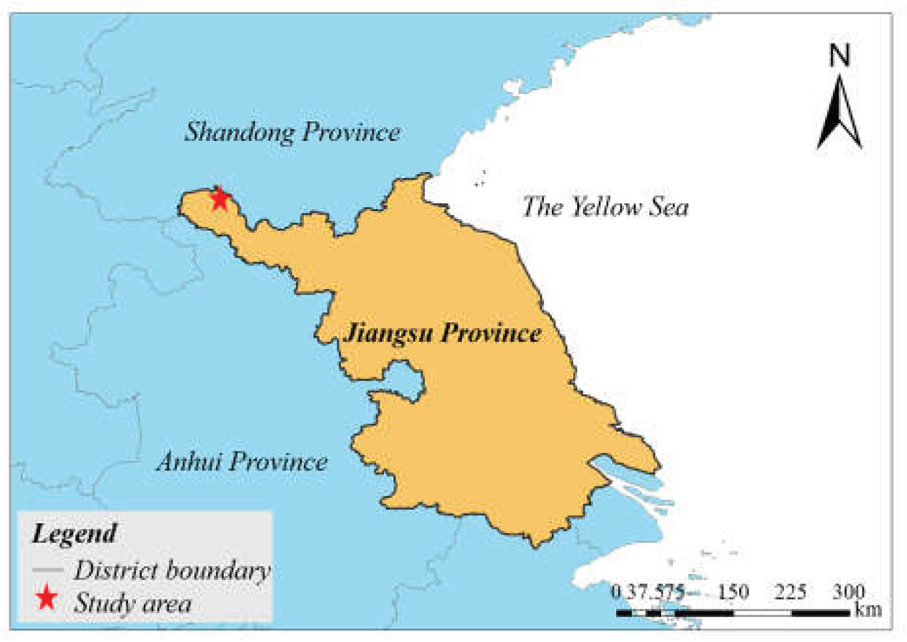
Figure 2.
XRD patterns of coal gangue and fly ash.
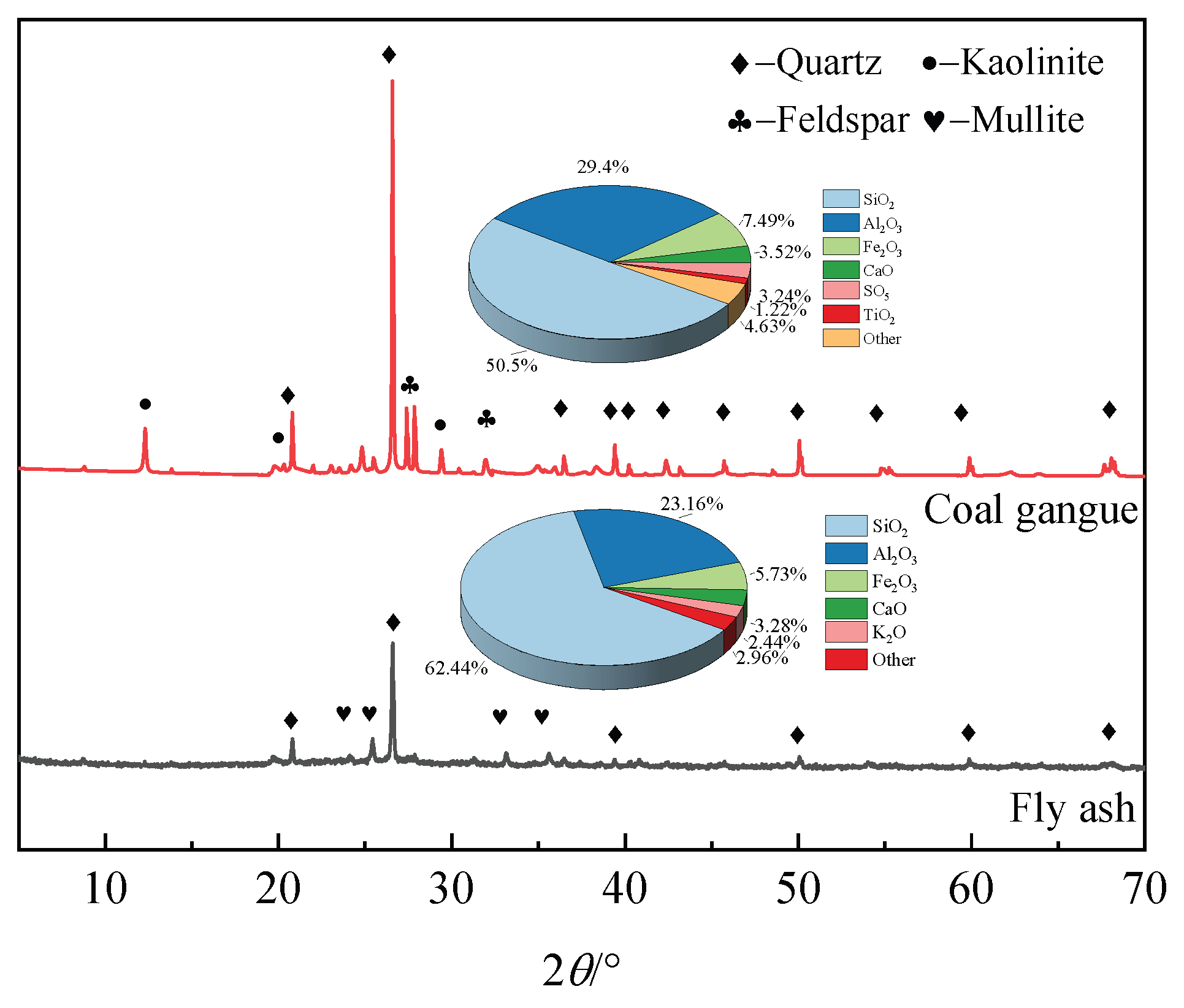
Figure 3.
Experimental flowchart.
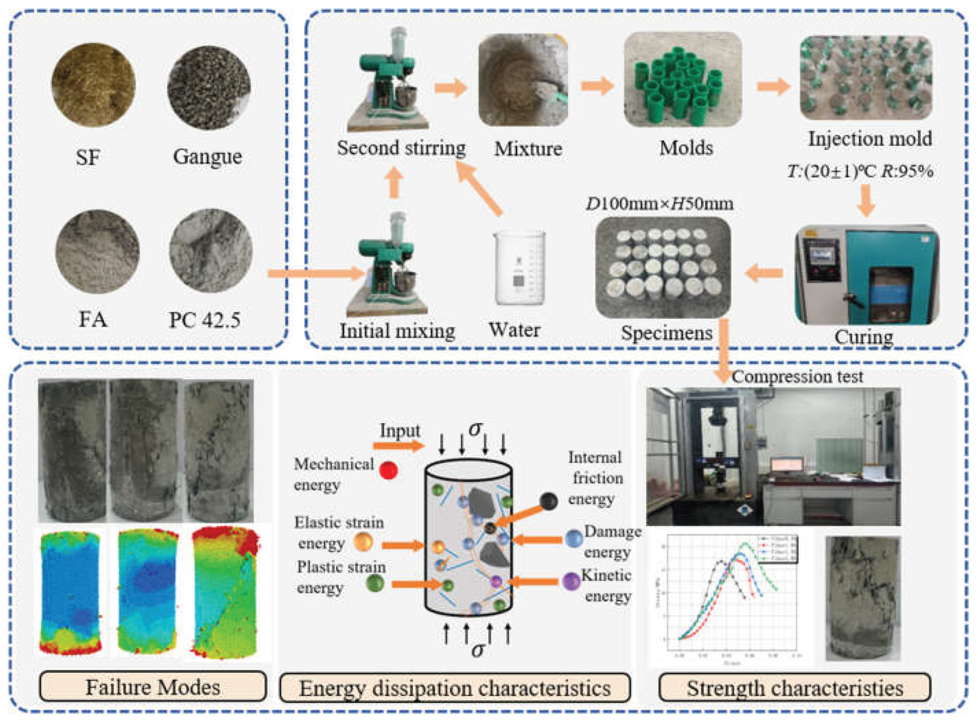
Figure 4.
Stress-strain curves (a) ωFA=5% (b) ωFA=10% (c) ωFA=15%.
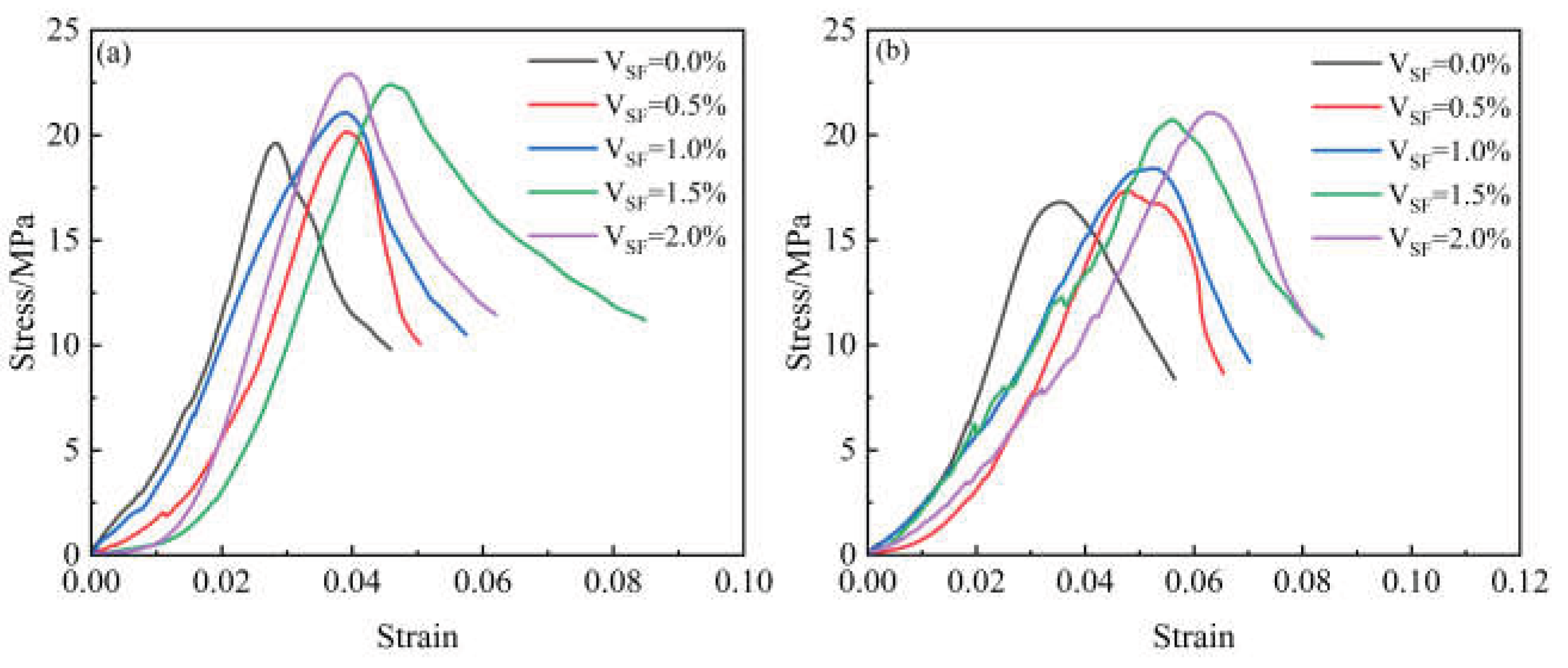
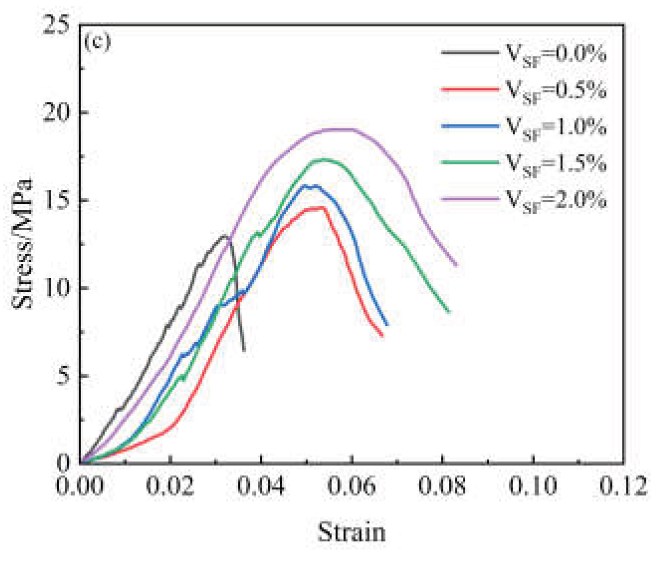
Figure 5.
Influence of different SF and FA contents on FGB’s (a) elastic modulus (b) axial strain and (c) peak stress.
Figure 5.
Influence of different SF and FA contents on FGB’s (a) elastic modulus (b) axial strain and (c) peak stress.
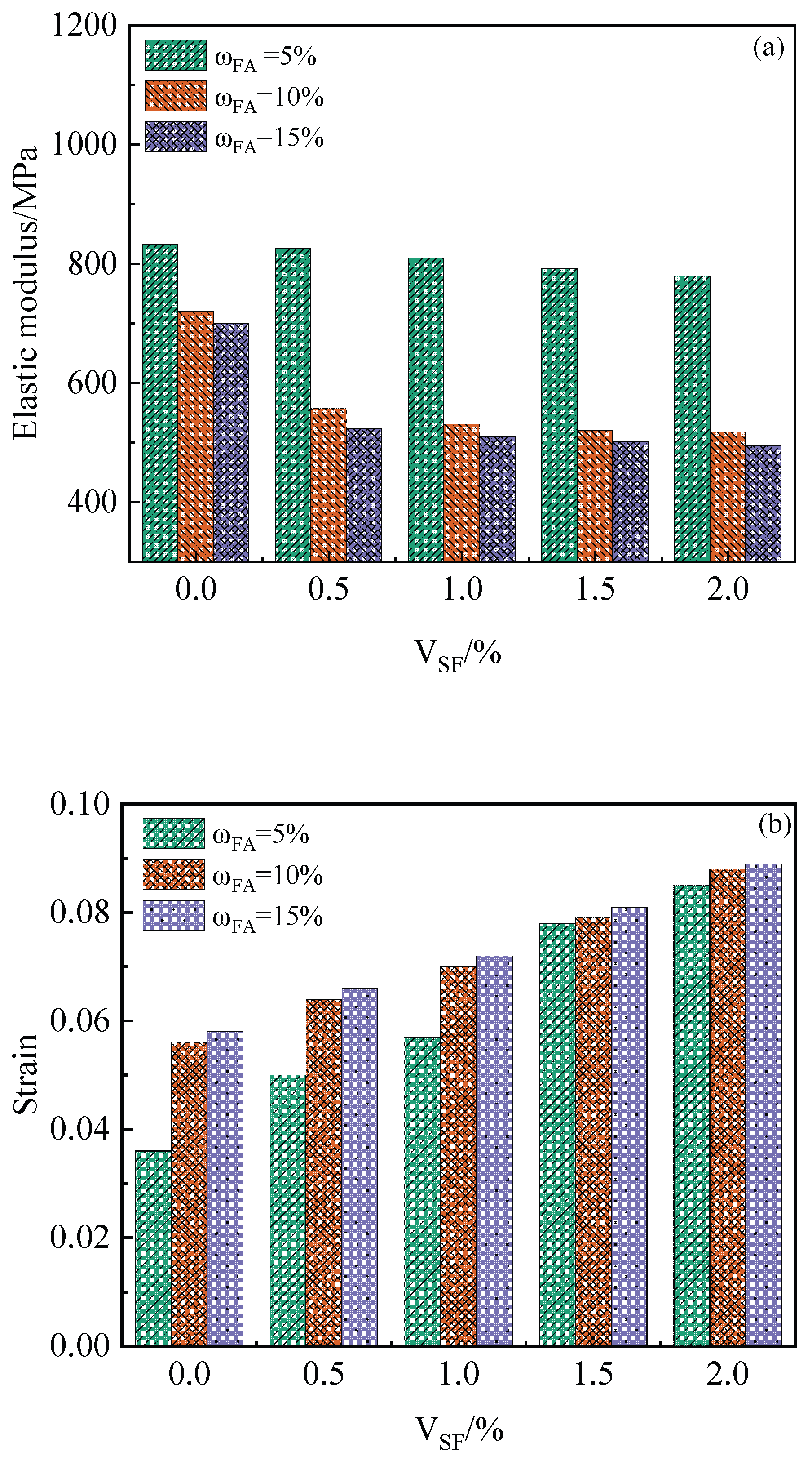
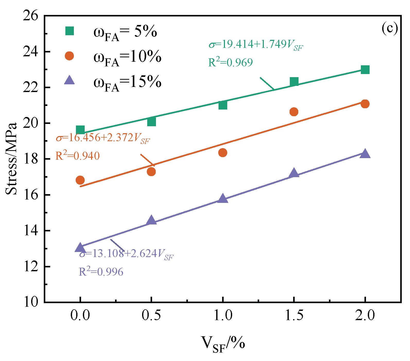
Figure 6.
Relationship between Ue and Ud in the stress-strain curve of FGB specimen.
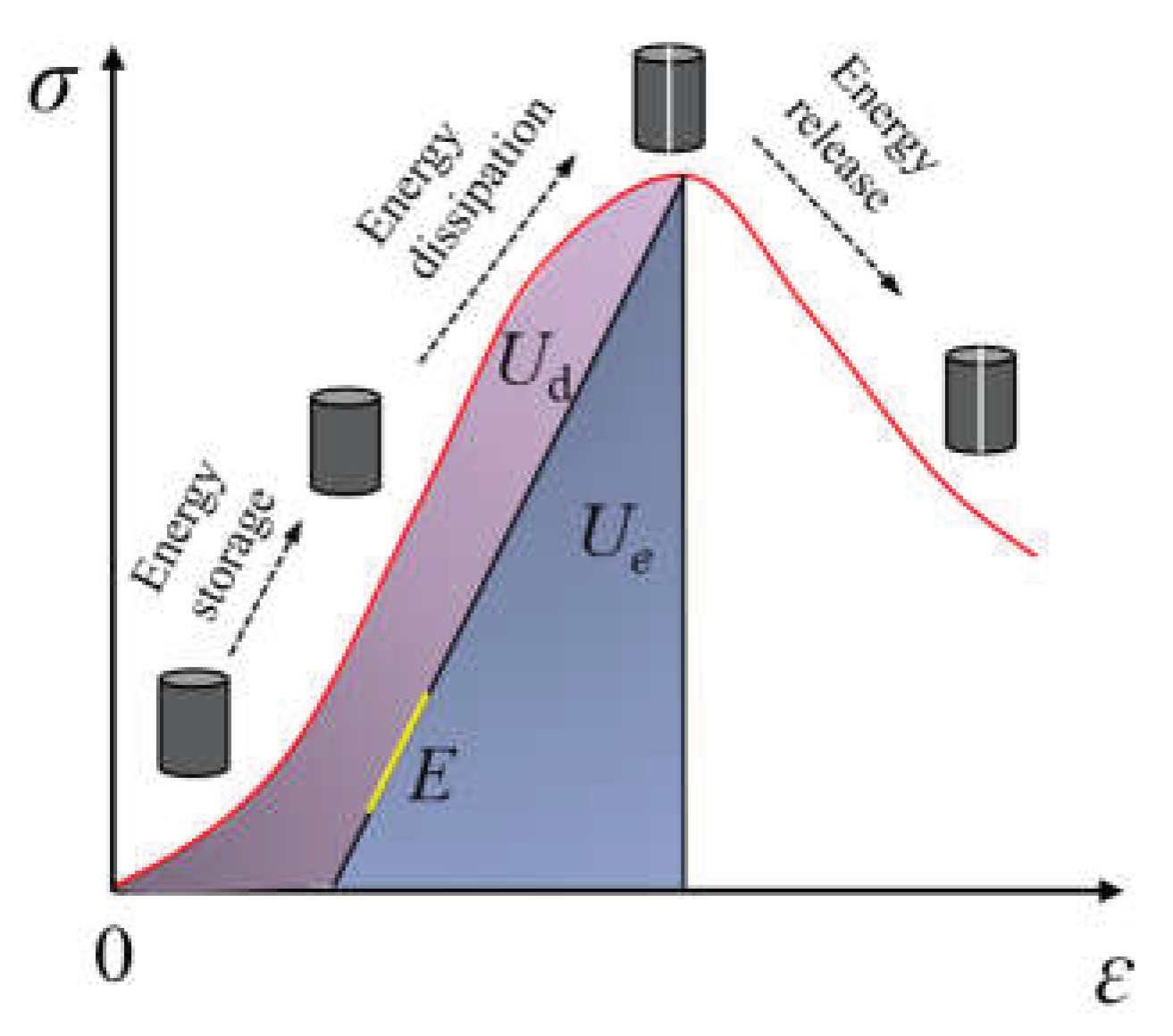
Figure 7.
Relationship between stress and energy evolution of FGB in the pre-peak stage (a)~(e): VSF=0.0%~2.0%.
Figure 7.
Relationship between stress and energy evolution of FGB in the pre-peak stage (a)~(e): VSF=0.0%~2.0%.
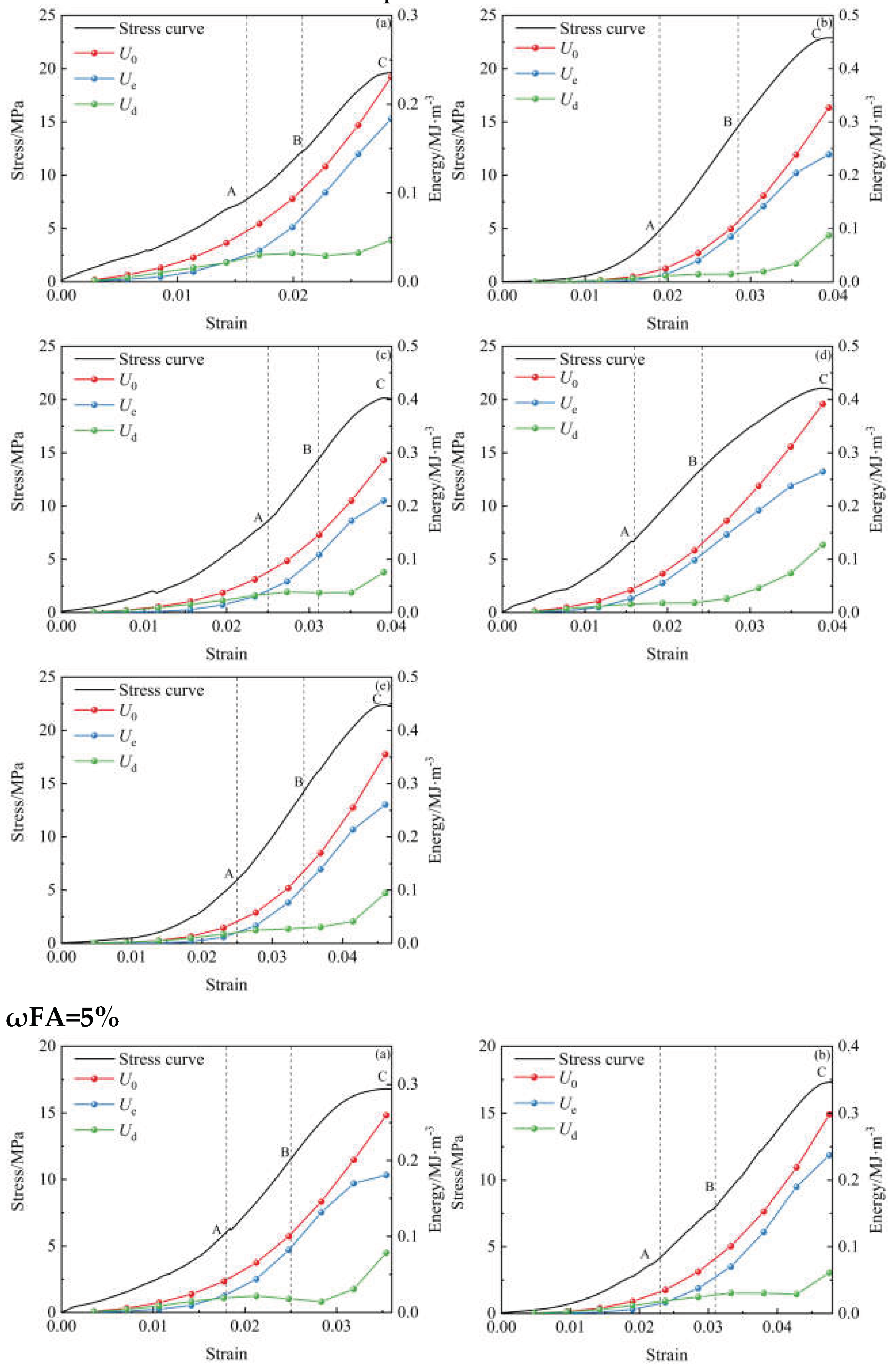
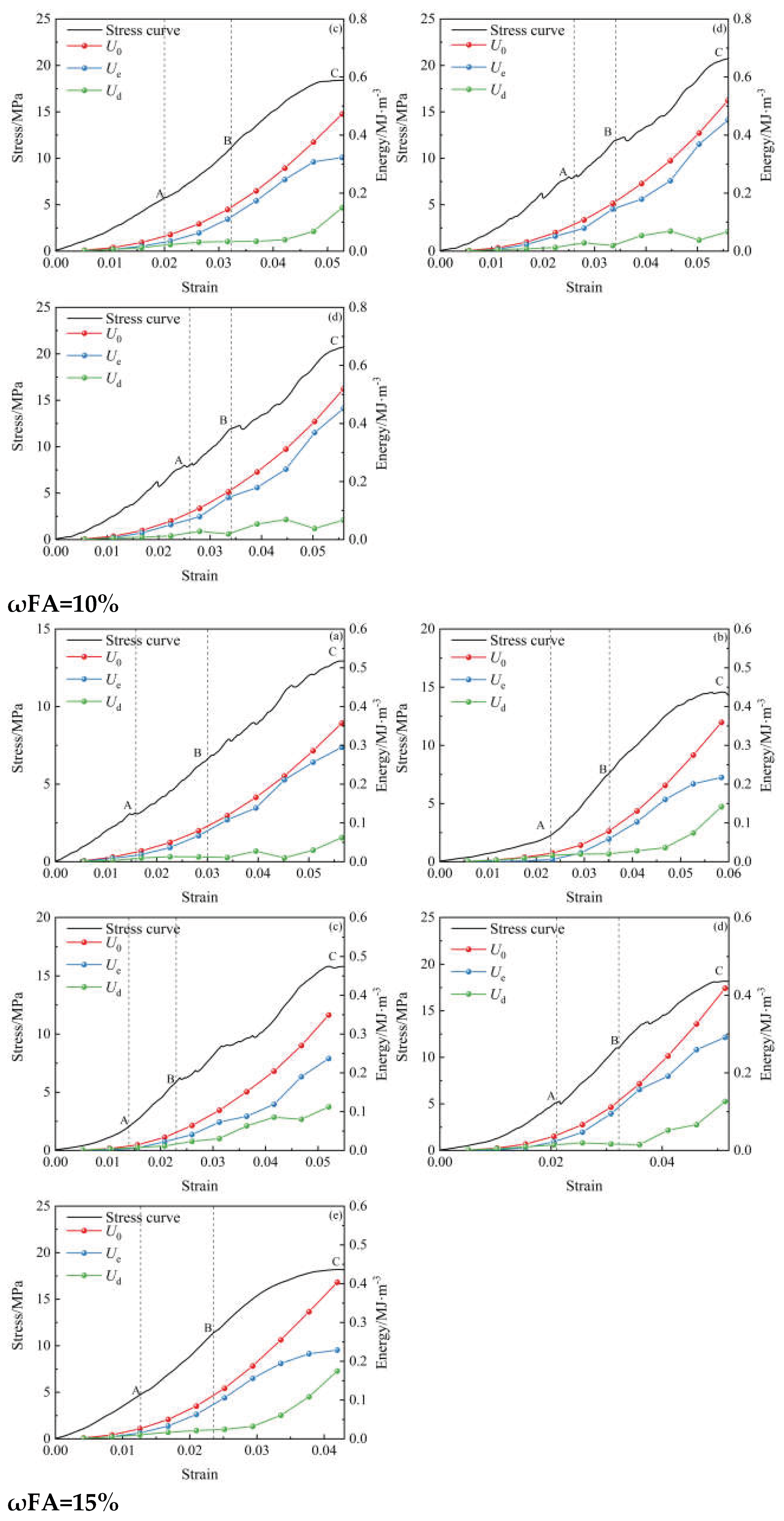
Figure 8.
Energy proportion at peak stress location (a) ωFA=5% (b) ωFA=10% (c) ωFA=15%.
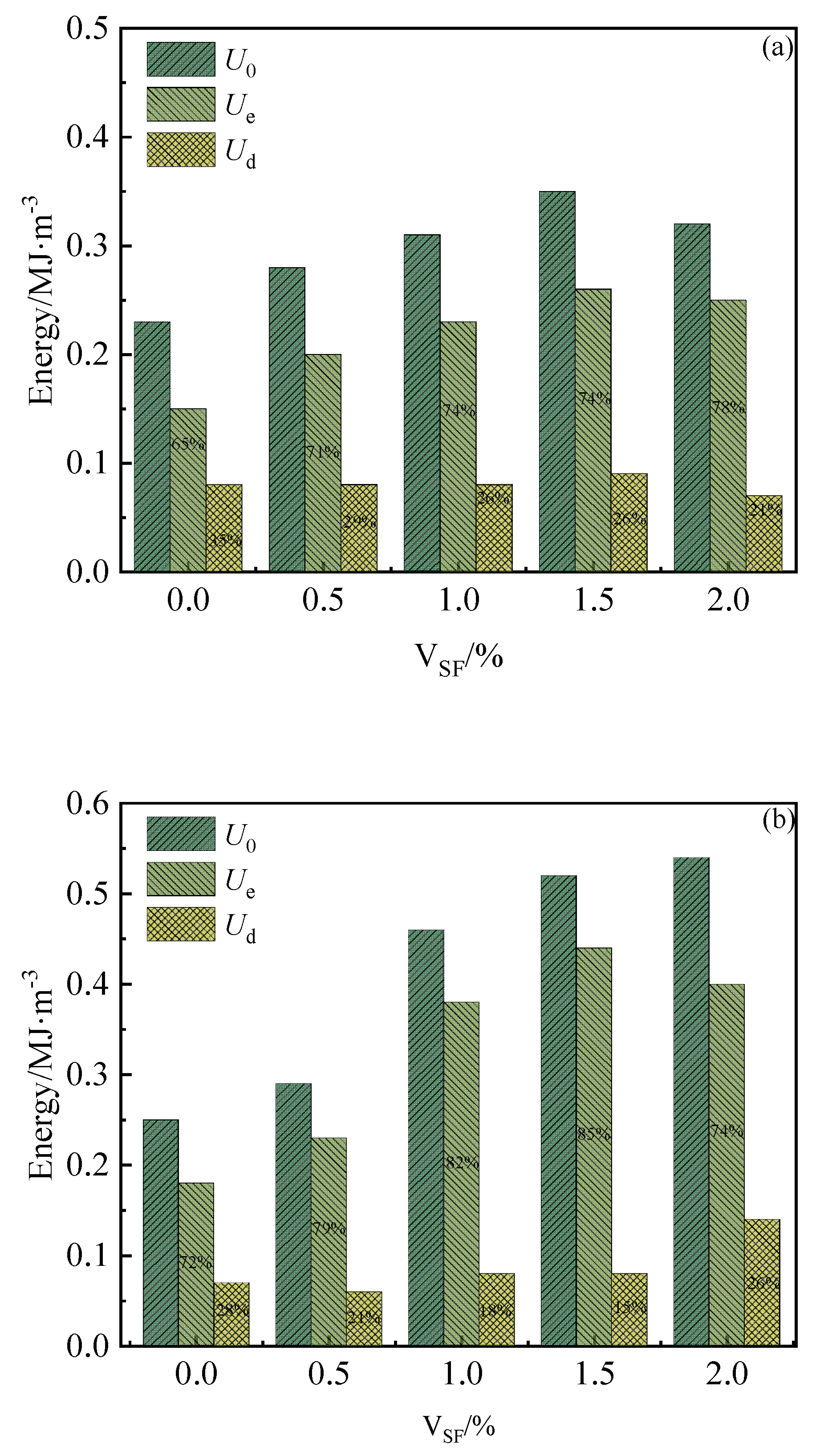
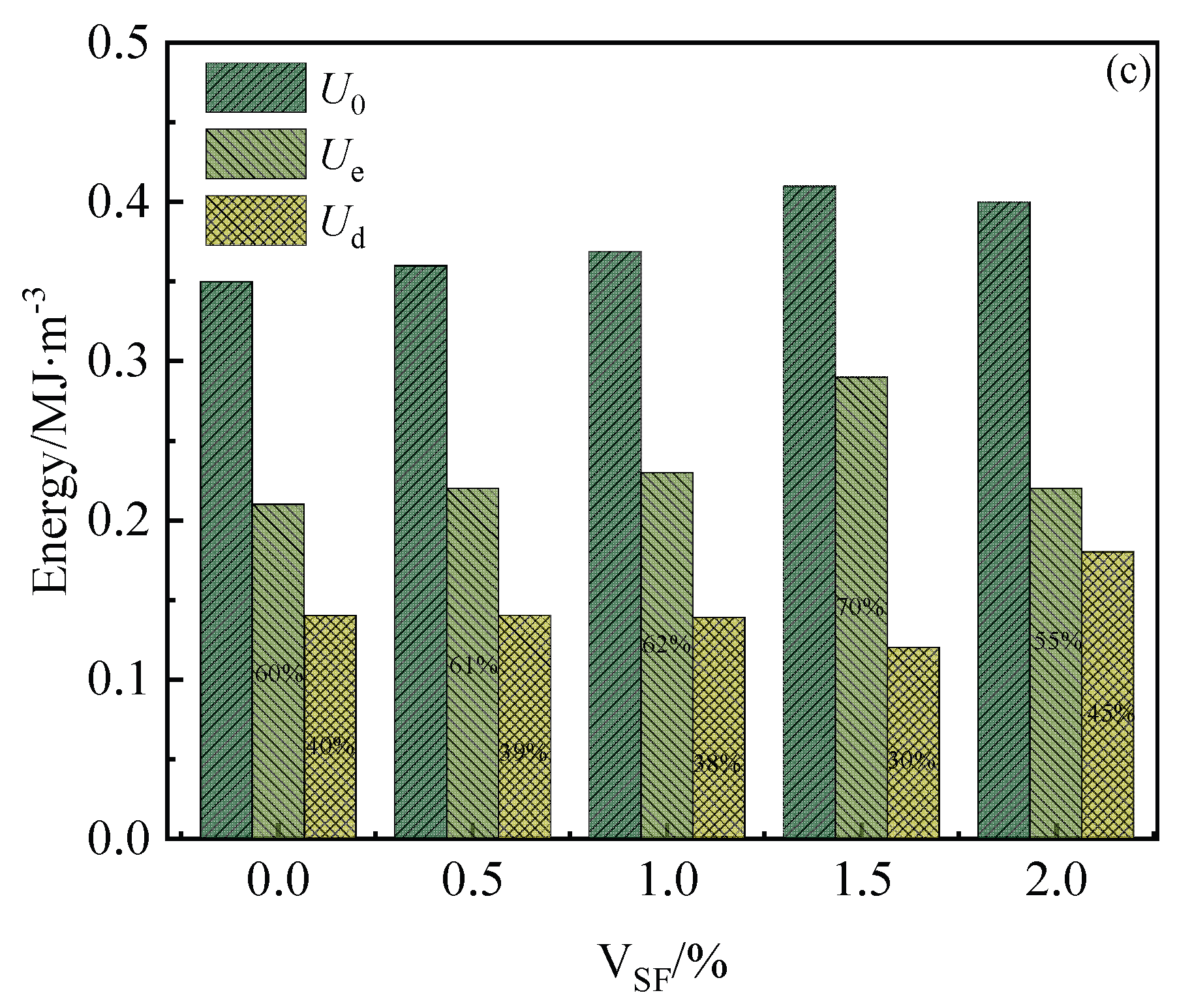
Figure 9.
Influence of SF and FA on the elastic energy dissipation ratio of FGB.
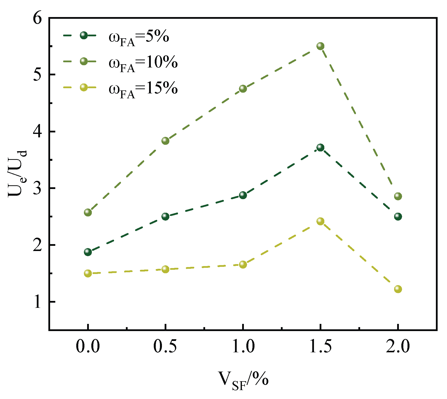
Figure 10.
Energy conversion mechanism of FGB under uniaxial loading.
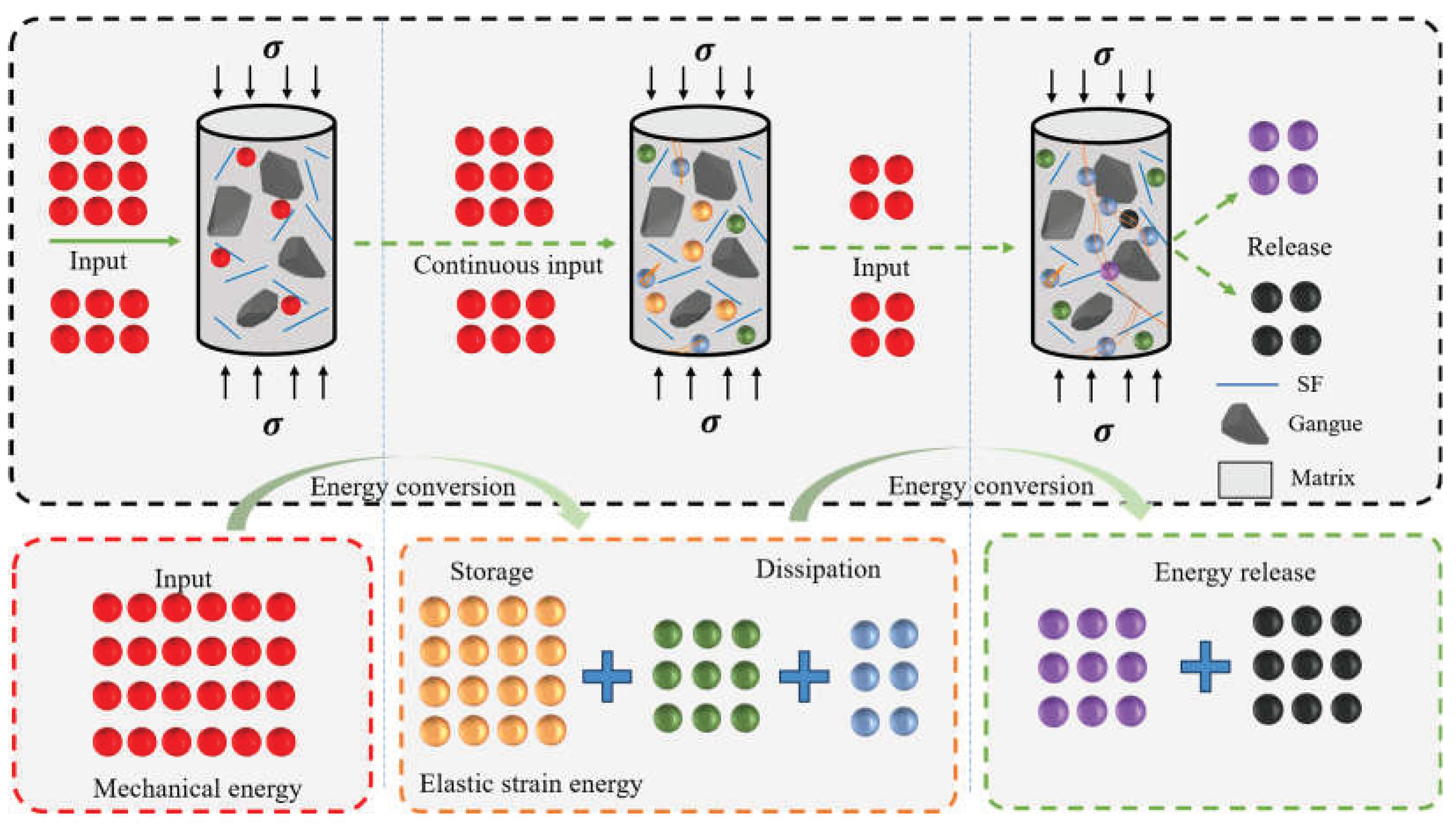
Figure 11.
Macroscopic failure modes of FGB specimens.
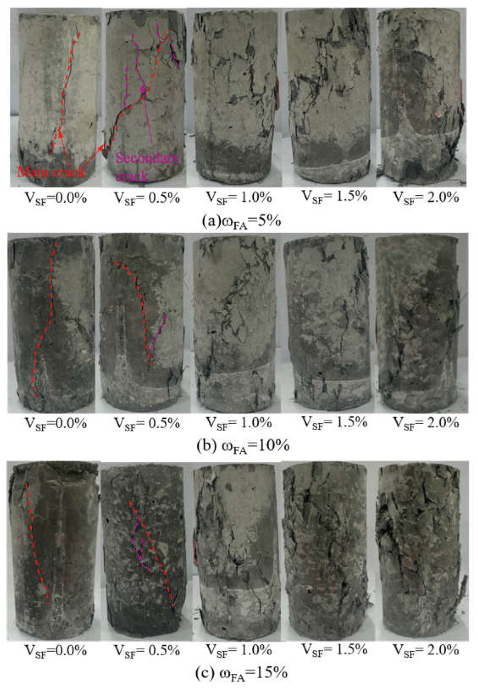
Figure 12.
Flowchart for uniaxial compression tests in PFC 3D.
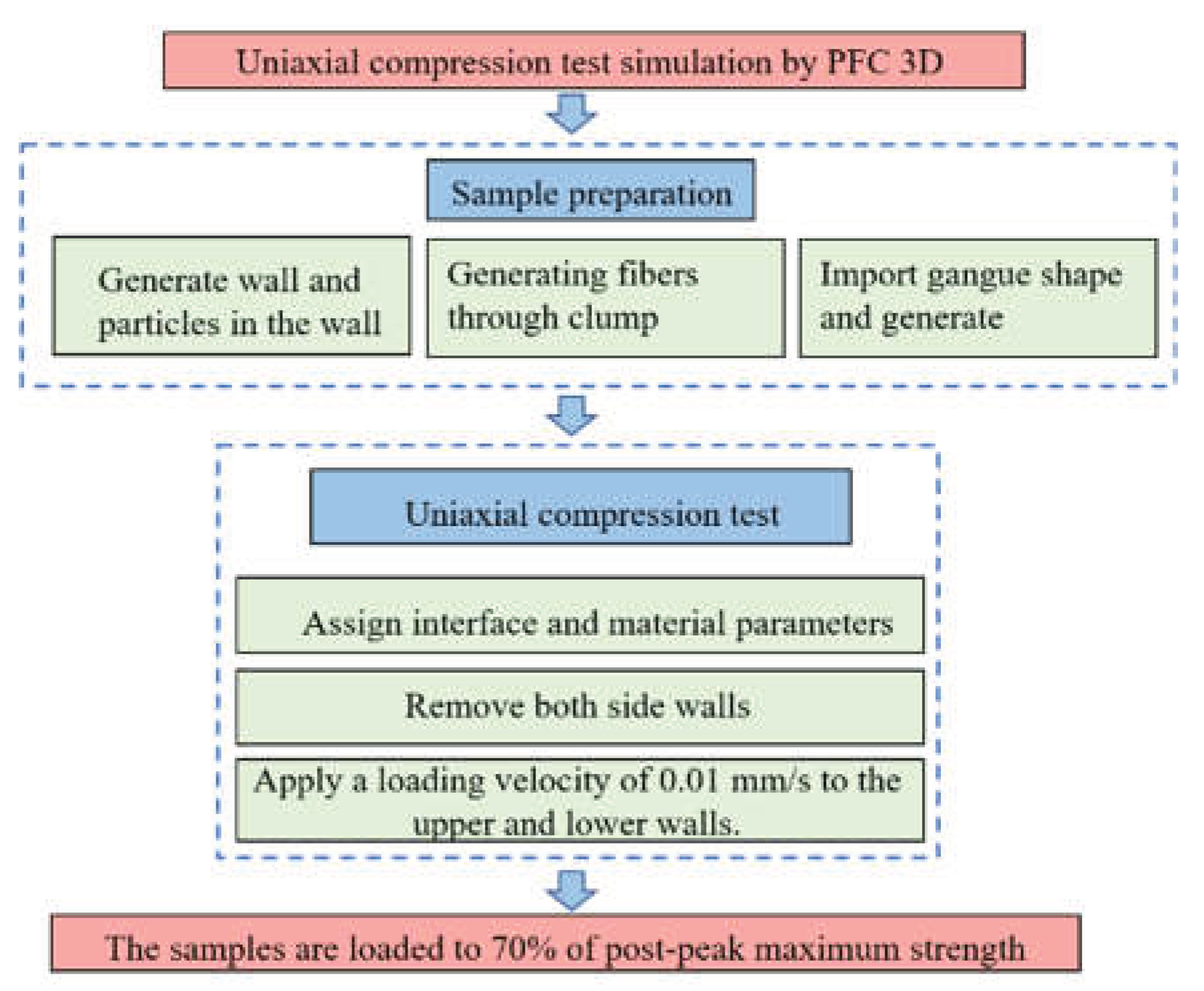
Figure 13.
Schematic diagram of the numerical model.
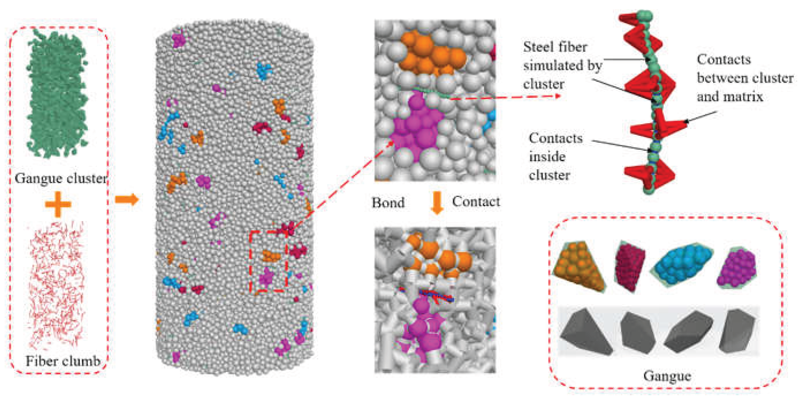
Figure 14.
Fiber pull-out test (a) schematic diagram; (b) comparison of force-displacement curves between experiment (Zhou et al. 2025) and DEM simulation.
Figure 14.
Fiber pull-out test (a) schematic diagram; (b) comparison of force-displacement curves between experiment (Zhou et al. 2025) and DEM simulation.
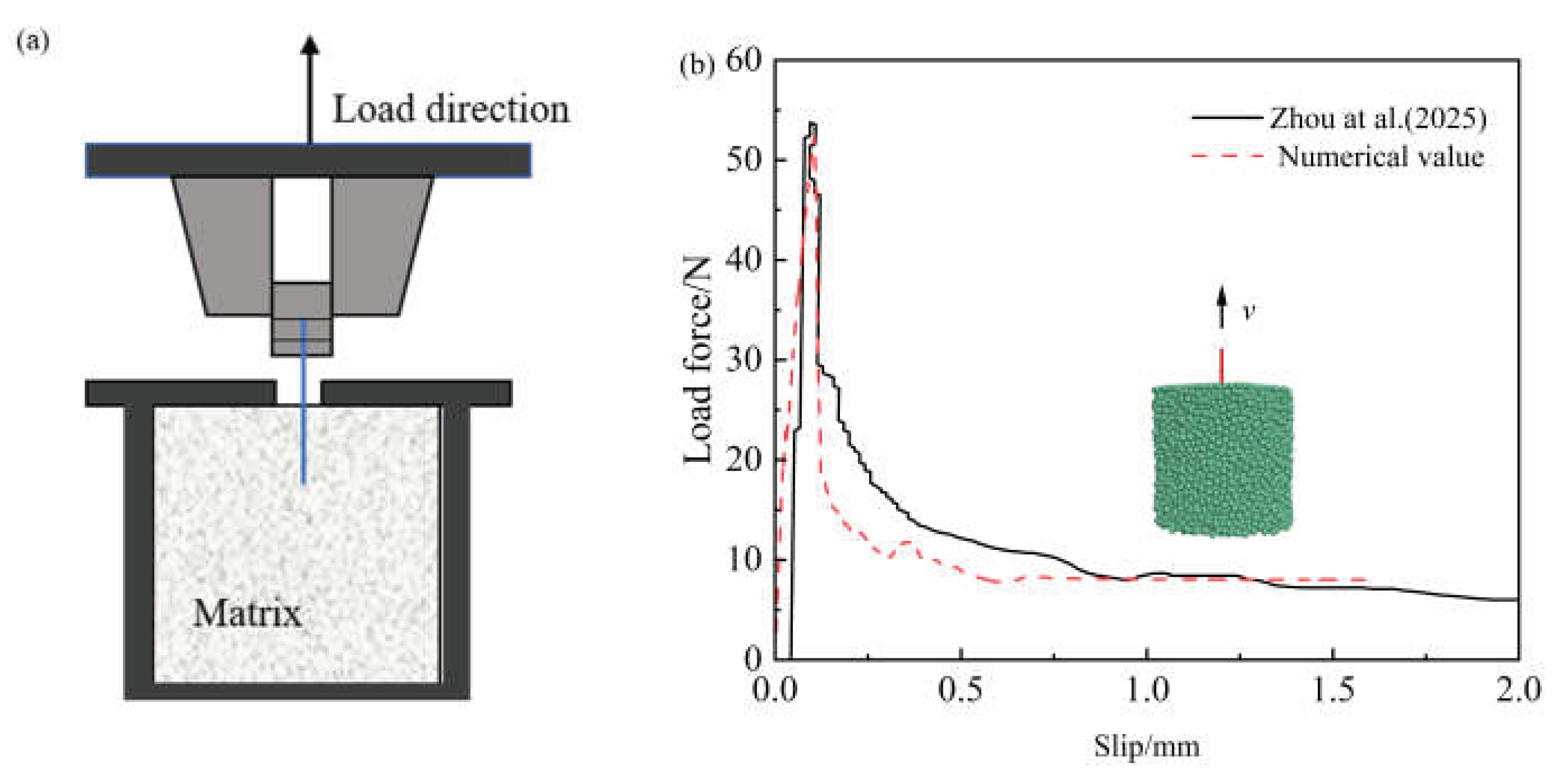
Figure 15.
Parameter calibration comparison.
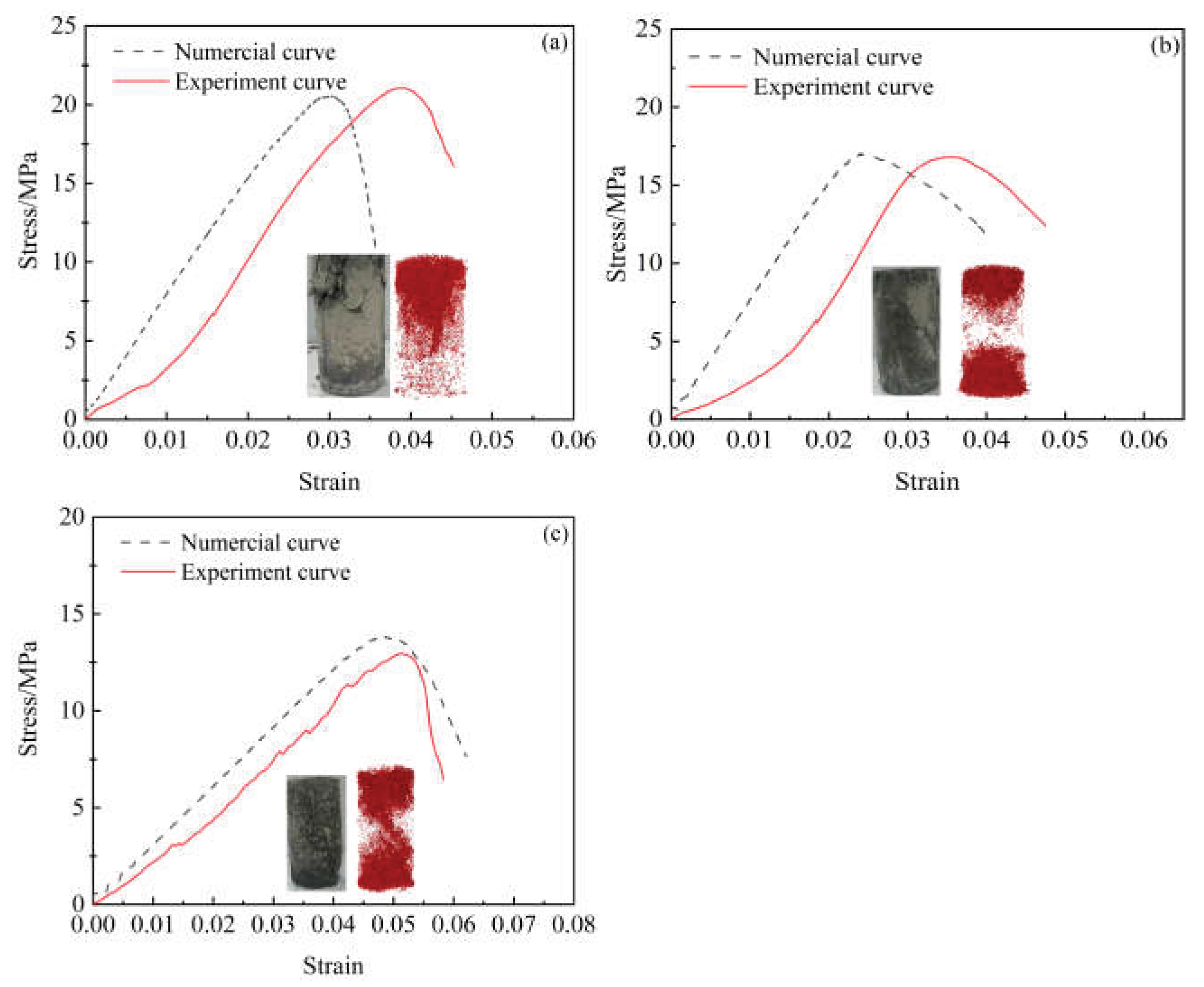
Figure 16.
Crack development stages in FGB under uniaxial loading.
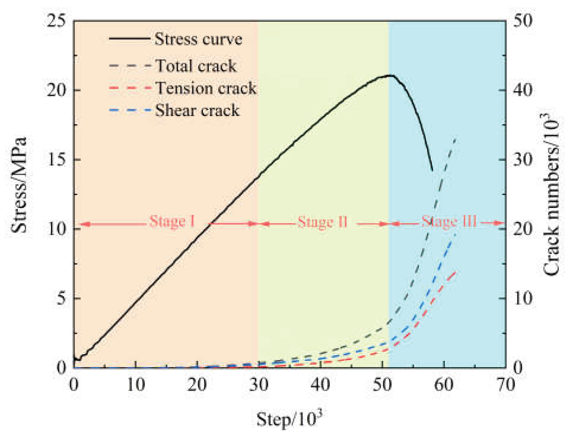
Figure 17.
Crack evolution at different stages of FGB specimen (ωFA=5%).
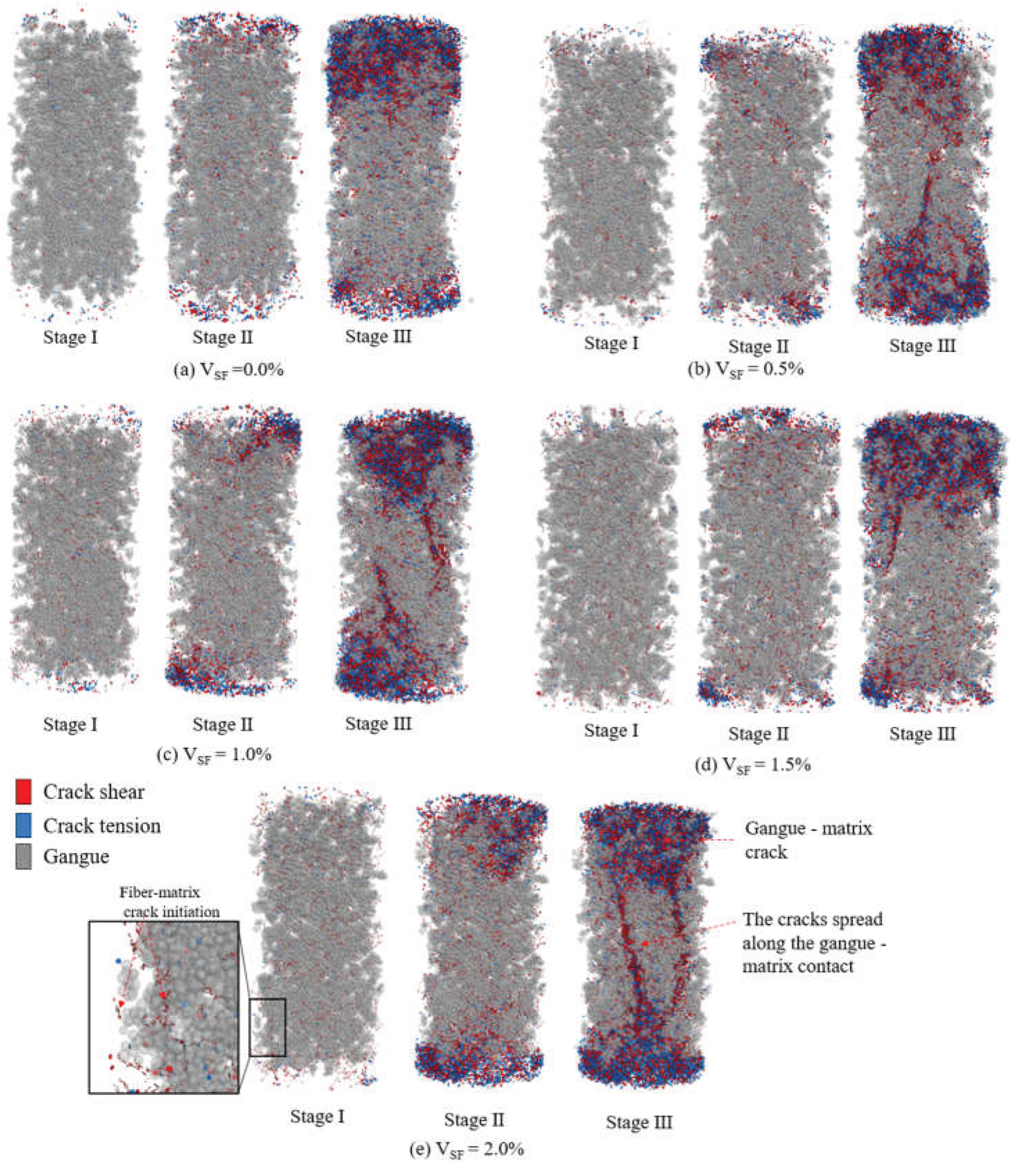
Figure 18.
Characteristics of crack propagation.
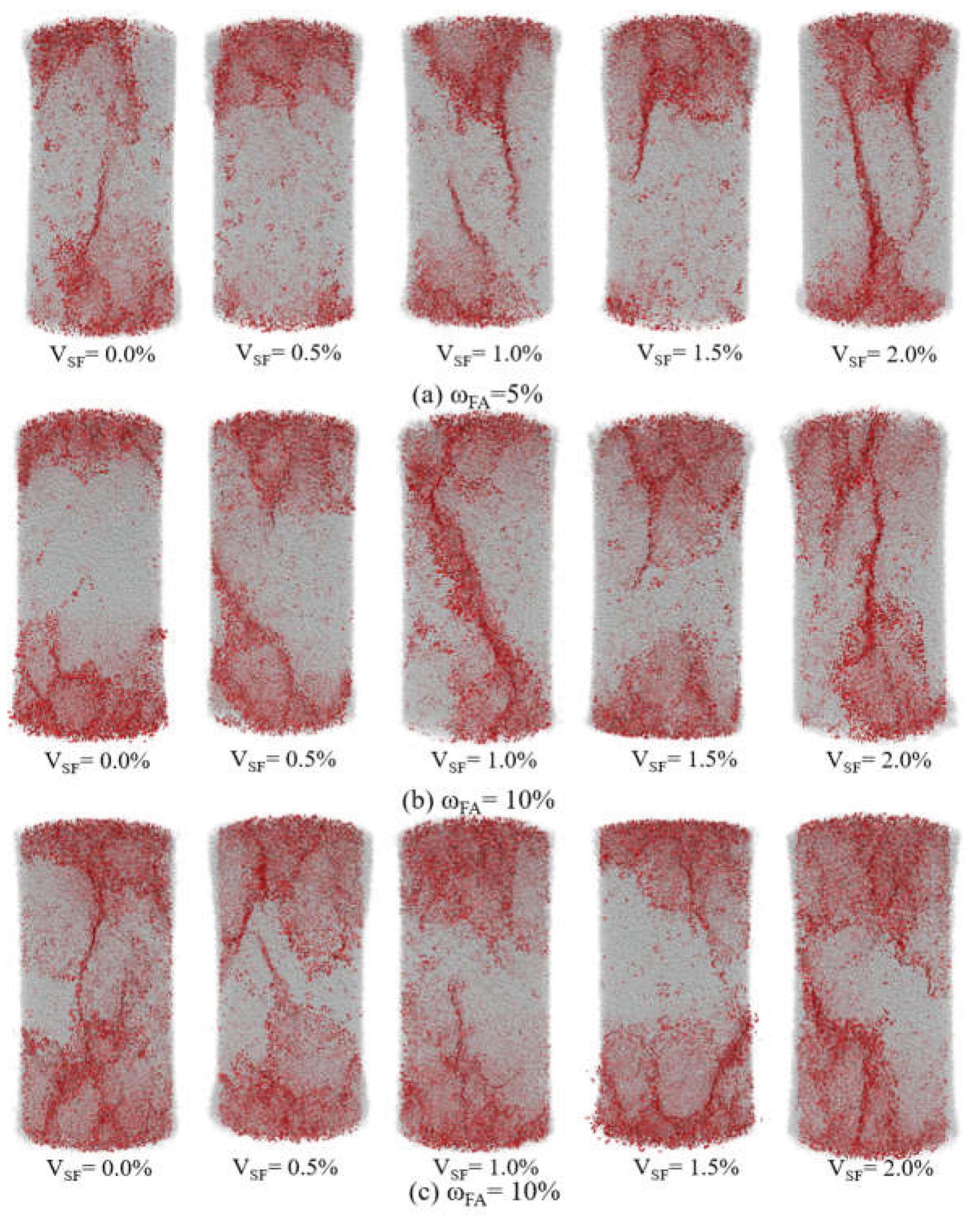
Figure 19.
Crack quantity characteristics (a)~(c): ωFA = 5~15%.
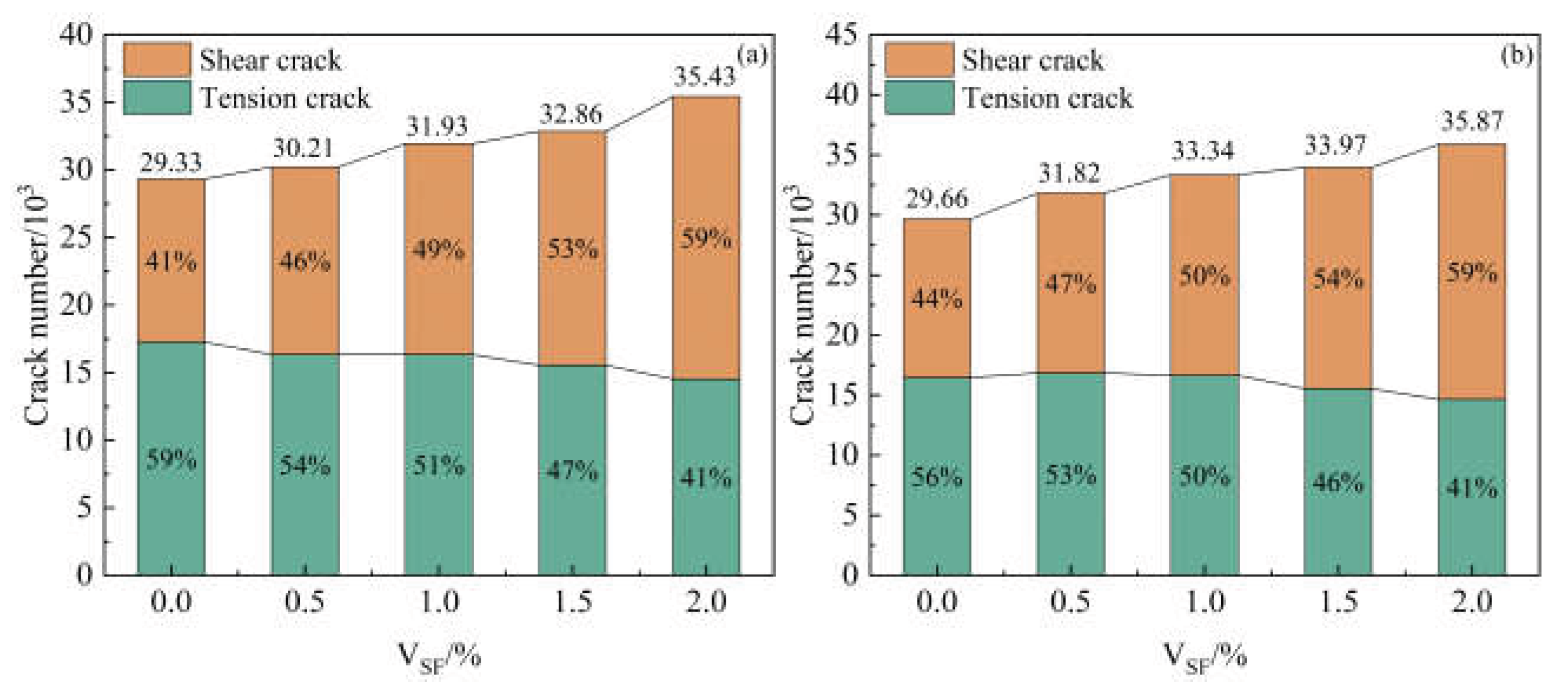
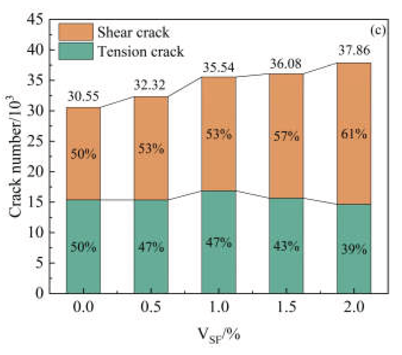
Figure 20.
Displacement field distribution after uniaxial compression failure.
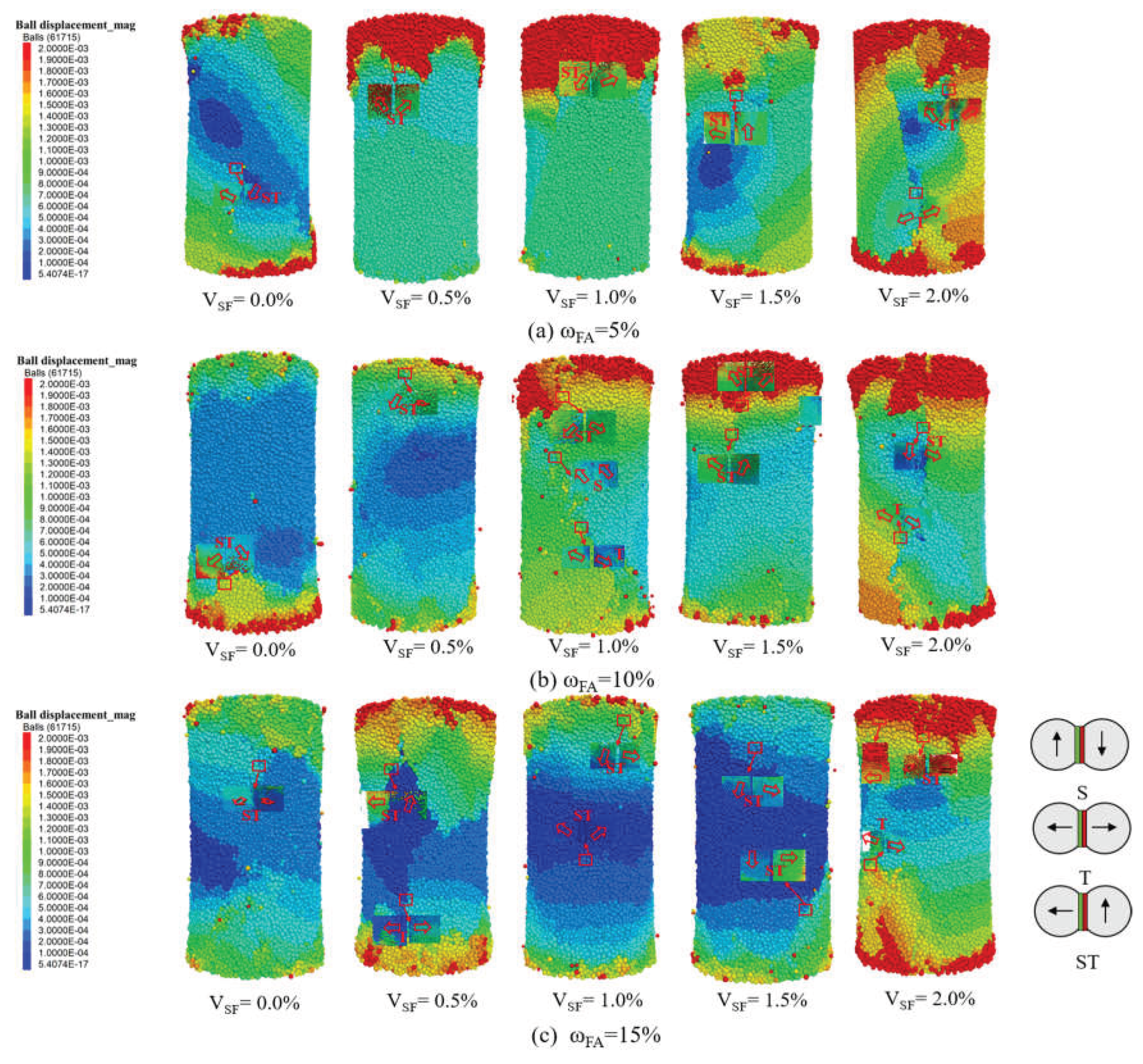
Figure 21.
Distribution of average normal contact force (a)~ (e): VSF=0.0%~2.0%.
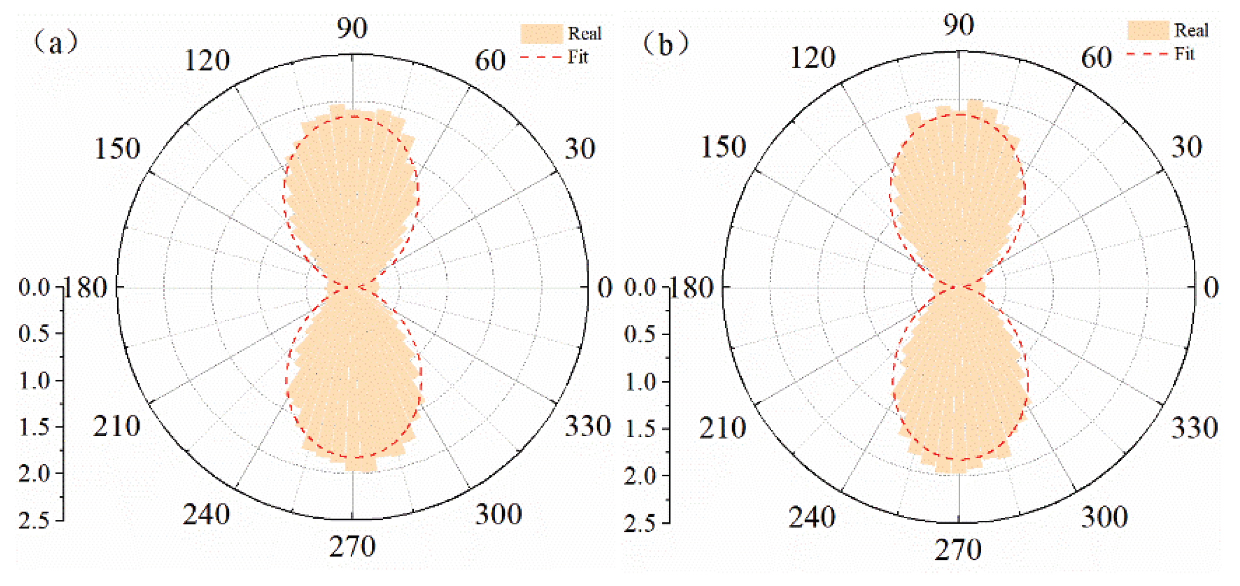
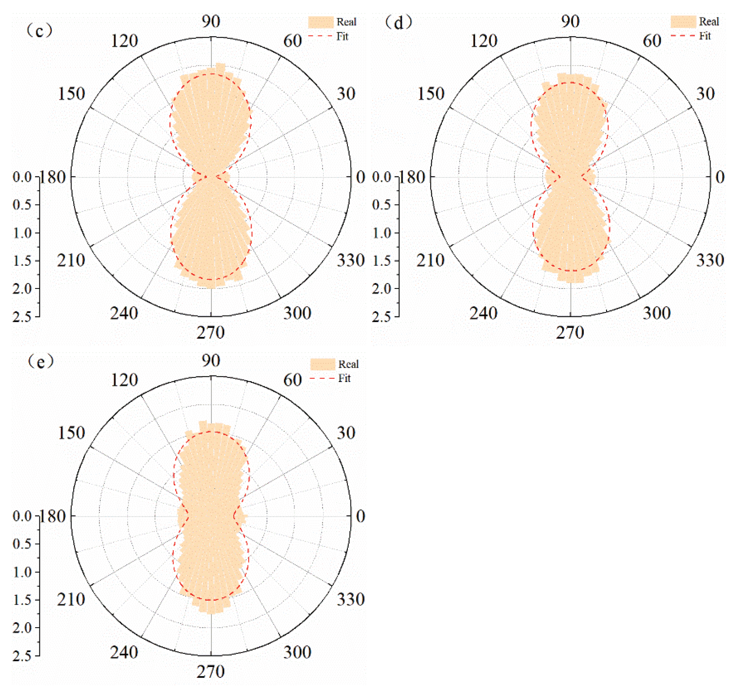
Figure 22.
Evolution of strong force chains for ωFA=5% (a) VSF=0.0%; (b) VSF=2.0%.
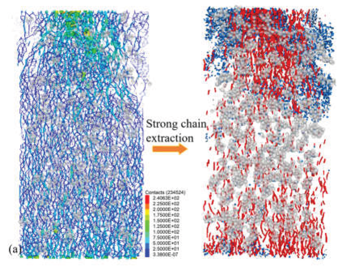
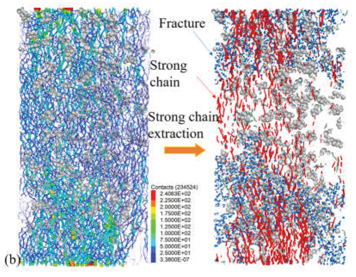
Figure 23.
Force chain distribution for ωFA=5% (a) VSF=0.0%-Stage III (b) VSF=2.0%-Stage II (c) VSF=2.0%-Stage III.
Figure 23.
Force chain distribution for ωFA=5% (a) VSF=0.0%-Stage III (b) VSF=2.0%-Stage II (c) VSF=2.0%-Stage III.
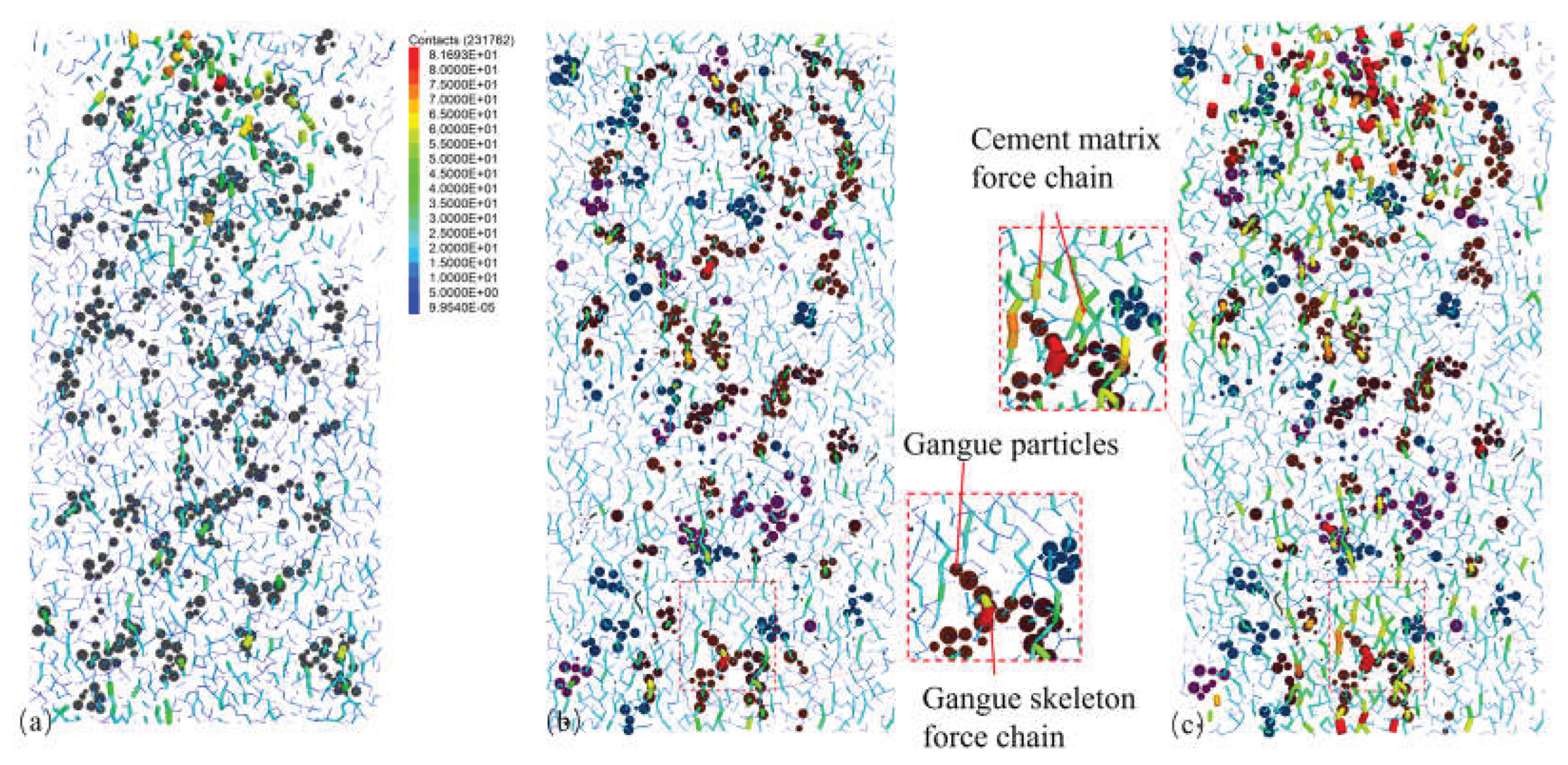

Table 1.
Fiber performance parameters.
| Materials | Density/(g·cm-3) | Tensile strength/MPa | Length/mm | Diameter/mm |
| Steel fiber | 7.85 | 2850 | 13 | 0.2 |
Table 2.
Types of fly ash compound.
| Material type | SiO2 | Al2O3 | Fe2O3 | K2O | CaO | TiO2 | MgO | Na2O | SO5 | Other |
| Fly ash | 50.497 | 29.398 | 7.499 | 1.782 | 3.520 | 1.220 | 1.063 | 0.882 | 3.236 | 0.903 |
| Gangue | 62.439 | 23.156 | 5.731 | 2.442 | 3.275 | 0.762 | 0.568 | 1.056 | 0.168 | 0.403 |
Table 3.
Experimental Scheme for FGB Preparation.
| Specimens | ωFA/% | VSF/% | Specimens | ωFA/% | VSF/% | Specimens | ωFA/% | VSF% |
| 1 | 5 | 0.0 | 6 | 10 | 0.0 | 11 | 15 | 0.0 |
| 2 | 0.5 | 7 | 0.5 | 12 | 0.5 | |||
| 3 | 1.0 | 8 | 1.0 | 13 | 1.0 | |||
| 4 | 1.5 | 9 | 1.5 | 14 | 1.5 | |||
| 5 | 2.0 | 10 | 2.0 | 15 | 2.0 |
Table 4.
Parameters for cement matrix, steel fiber, and ITZ.
| Microscopic parameter | Matrix | ITZ | Steel Fiber | ||||
| ωFA=5% | ωFA=10% | ωFA=15% | ωFA=5% | ωFA=10% | ωFA=15% | ||
| Particle radius(mm) | 0.5~0.7 | 0.5~0.7 | 0.5~0.7 | - | - | - | 0.3 |
| Density(kg/m3) | 2500 | 2500 | 2500 | - | - | - | 7800 |
| Elastic modulus (GPa) | 22 | 20 | 19 | 10 | 10 | 9 | 20 |
| Damping | 0.2 | 0.25 | 0.25 | 0.1 | 0.1 | 0.1 | 0.1 |
| Stifness ratio | 2.0 | 2.0 | 2.0 | 2.0 | 2.0 | 2.0 | 2.0 |
| Pb_emod (GPa) | 20 | 19 | 17 | 22 | 20 | 21 | 180 |
| Tensile strength (MPa) | 200 | 195 | 185 | 200 | 195 | 185 | 4500 |
| Cohesion (MPa) | 320 | 320 | 300 | 250 | 250 | 230 | 4000 |
| Friction angle (degree) | 35 | 30 | 40 | 35 | 30 | 40 | 0 |
| Friction coefcient | 0.4 | 0.4 | 0.5 | 0.4 | 0.4 | 0.5 | 0.4 |
Table 5.
Parameters for fiber-matrix interface, fiber-aggregate, and fiber-fiber interfaces.
| Microscopic parameter | Fiber-matrix | Fiber-aggregate | Fiber–fiber |
| Elastic modulus (GPa) | 15 | 15 | 15 |
| Damping | 0.2 | 0.2 | 0.2 |
| Stifness ratio | 2.0 | 2.0 | 2.0 |
| Pb_emod (GPa) | 20 | - | - |
| Tensile strength (MPa) | 280 | - | - |
| Cohesion (MPa) | 380 | - | - |
| Frictionangle (degree) | 35 | - | - |
| Friction coefcient | 0.4 | 0.4 | 0.4 |
| sb_soft | 8 | - | - |
| sb_cut | 0.3 | - | - |
Disclaimer/Publisher’s Note: The statements, opinions and data contained in all publications are solely those of the individual author(s) and contributor(s) and not of MDPI and/or the editor(s). MDPI and/or the editor(s) disclaim responsibility for any injury to people or property resulting from any ideas, methods, instructions or products referred to in the content. |
© 2026 by the authors. Licensee MDPI, Basel, Switzerland. This article is an open access article distributed under the terms and conditions of the Creative Commons Attribution (CC BY) license (http://creativecommons.org/licenses/by/4.0/).
Copyright: This open access article is published under a Creative Commons CC BY 4.0 license, which permit the free download, distribution, and reuse, provided that the author and preprint are cited in any reuse.