

Submitted:
04 September 2026
Posted:
07 September 2026
You are already at the latest version
Abstract
Achievable functionality of metasurfaces and metagratings strongly depends on the properties of the materials, of which their components are made. The key question is which loss level is still acceptable for a particular targeted functionality. In this study, it is numerically demonstrated that for meta-atoms of supercell-based metasurfaces with phase-gradient enabled functionality the loss level sets significant restrictions. Moreover, it pre-determines the range of geometrical-parameter variation needed to cover the entire phase range. For metagratings composed of equal meta-atoms, the loss related restrictions can be mitigated, provided that asymmetric diffractions are targeted. The examples are presented for THz range, for which conventional dielectrics and the (ultra-)high permittivity composites and unbiased ferroelectrics are considered as the candidate materials for metasurfaces and metagratings. The results directly demonstrate the effects exerted by the dielectric loss tangent, and the ones exerted by a selected geometrical parameter when the loss tangent is kept.
Keywords:
dielectric resonator
; losses
; metasurface
; metagrating
; phase gradient
; asymmetric transmission
; ferroelectric
; cross-polarization
; diffractions
1. Introduction
Metasurfaces or quasi-planar metamaterials have fully changed the research landscape in the fields of photonics, microwaves and new materials [1,2]. Phase gradients designed at the metasurface for reflected/transmitted waves enable the supercells needed for diverse wavefront-manipulation functionalities, among which deflection and focusing are best known [3,4,5,6,7]. For coding and intelligent metasurfaces, a few different values of the phase are needed [8,9]. In the above-mentioned cases, the required set of different phases (along with the nearly the same wave magnitudes) is obtained by using dielectric, i.e., Mie type, or quasi-planar metallic subwavelength resonators which have slightly or moderately different sizes and/or geometry within supercells. For some functionalities, like absorbers [10,11] or color filters [12], a phase gradient is not needed, so that the metasurface is composed of equal resonators. Notably, different wave phases can be created by using the same but differently rotated resonance elements that create the geometric phase (also known as Pancharatnam-Berry phase) [7], whose capability of polarization manipulation relates to PSHE [13,14]. Recently, a lot of attention has been paid to the gradient and non-gradient metasurfaces exploiting advanced physics, like BIC [15], topological effects [16], and non-Hermiticity [17,18]. In case of dielectric resonators, low-loss materials like Si are commonly used in different parts of electromagnetic spectrum, although it remains unclear which level of loss is sufficient for the targeted functionality, and how the achievable functionality is affected by loss level, which may be different due to doping, impurities, or specifics of fabrication. Losses in materials, of which metasurfaces and metagratings are made, have been expected to play at least three roles: 1) enable absorbers in different parts of electromagnetic spectrum; 2) enable non-Hermiticity related effects in transmission, reflection and wave guiding; 3) limit functionality of gradient metasurfaces and diffractive metagratings. Despite being unambiguous, in some senses, the question of whether higher material losses are always worser suited for the targeted functionality has not yet been answered exhaustively. Therefore, it is worth estimating the loss level suitable for the most common functionalities. Moreover, metagratings and metasurfaces have been widely used in diffraction-enabled AT devices [19,20,21,22,23]. Notably, photonic crystals, layered metamaterials, and specially designed metagratings have been widely used [24,25,26,27,28,29] for AT. Janus metasurfaces is the recent name that has been applied at least to a part of the AT enabling dielectric and metallic quasi-planar metastructures [30,31,32].
In this paper, effect of losses in high-permittivity and very-high-permittivity materials of resonators, on which the metasurface’s/metagrating’s unit cells (meta-atoms) are based, on the resulting functional capability. The main motivation relates to the necessity of understanding of the role of losses in possible restrictions of such functionalities like deflection, focusing, coding, and asymmetric transmission. It is attempted to estimate which loss level is still acceptable, and when a less lossy material is needed. This should help to extend the range of applicable materials and properly manage the way of choosing the suitable options. A particular task is the assessment of very-high-permittivity materials, which are attributed to unbiased ferroelectrics and some types of the composites, which typically show low losses at microwave frequencies, but their capability to keep an acceptably low level of loss at higher frequencies, e.g., at THz frequencies, is not guaranteed [33,34]. It is worth mentioning the earlier studies focused rather on functional capability, in which not all parameters of such materials have been properly or fully taken into account [35,36]. At the same time, the results are known, which show the trend of the losses to grow while being shifted from microwave to THz frequencies, and the dielectric loss tangent is typically larger than 0.01; e.g., see [37,38,39]. Despite this, there were many attempts to realize the structures comprising such very-high-permittivity materials [37,40]. Moreover, very recent [41] and even earlier experimental results show that the loss tangent can be significantly decreased for some materials. In this paper, based on the simulation results, it will be shown which loss levels for which functionalities are sufficient. Although the present study is restricted to THz frequencies, the obtained estimates can be usable for higher frequency ranges. The below discussed results are obtained using CST Studio Suite 2020 [42].
2. Studied Meta-Atoms
The meta-atoms of three types are considered; see Figure 1. Each meta-atom contains 1) a cylindrical microresonator made of a (very-)high-permittivity material, 2) spacer, substrate or half-space, atop of which the resonators are placed, and 3) back-side metallic reflector (for one of three types). It is assumed that these meta-atoms will be used as the building blocks for gradient metasurfaces and nongradient metagratings.
For the metasurfaces, phase coverage within the supercell comprising different meta-atoms of the same type and the nearly constant high magnitude of the reflected or transmitted wave are the key functionality-enabling characteristics [1,2,3,4,5,6,7]. They pre-determine the capability of the examined meta-atoms in phase-gradient related functionalities, like deflection and focusing. The individual meta-atoms of gradient metasurfaces work in subdiffraction regime. In turn, the diffractive metagratings are composed of equal meta-atoms and need a higher-frequency operating range to obtain diffractions [19,21]. Notably, the studied meta-atoms are asymmetric along the cylinder vertical axis. This feature is common for most of the dielectric metasurfaces. Throughout the paper, rc and h stand for the radius and height of cylindrical microresonators, respectively, p denotes the transverse unit-cell size (it is equal to the period in case of equal meta-atoms), and ts is spacer thickness; ec and es are permittivity of the cylindrical resonators and spacer/substrate/half-space, respectively.
For the gradient metasurfaces capable of wavefront manipulation, the supercells are composed of the meta-atoms which should have closely spaced resonance frequencies, while the reflected or transmitted wave magnitude is close to unity. When the targeted functionality is deflection, the required phase variation of phase, f, along the surface is governed by the generalized Snell’s law [3,7]:
where l stands for EM wave’s length, ni and nt mean refractive indices, respectively, in the incidence/reflection and transmission regions, respectively; ai and at represent incidence and refraction angles. For the entirely reflective configuration, nt in (1) should be substituted by nr=ni, so that the phase gradient is still responsible for possible deviations of the reflected wave from the case of specular reflection. In case of focusing, a parabolic distribution of phase is needed. In one-dimensional case, it is given by [5,6,7]
where F means for the focal length. The energy balance yields
where T, R and A are, respectively, transmittance, reflectance, and absorptance. If the structure comprises the back-side reflector whose thickness is chosen to fully suppress transmission, it can be rewritten as R+A=1. Notably, absorption can be significantly enhanced at the resonances, so the trade-off is always needed at the design stage to create the required phase variations and simultaneously avoid unwanted absorption. To remind, forward and backward, i.e., upper- and lower-side illumination-case transmittances are the same in the subdiffraction regime due to Lorentz reciprocity, but they are typically different in the diffraction regime due to the propagating higher diffraction orders [24,28,43].
T+R+A=1,
3. Results and Discussion
In this section, the capability of microscale meta-atoms in the functionalities which is associated with gradient metasurfaces depends on the loss tangent of the resonator material, tand, is examined. Notably, absorption is generally not proportional to the extent of the lossy material [44,45], whereas the effect of tand can be significant for narrow resonances [46]. The consideration is restricted to the case of normal incidence. The spacer/substrate/lower half-space permittivity, es, is taken as 2.25.
3.1. Effect of Losses in Phase-Gradient Enabled Functionality
Figure 2 presents magnitudes and phases of the reflected wave shown in Figure 1(a) as a function of frequency, f, for the structures which comprise the back-side metallic reflector. The results are presented for three sets of rc, h, ec, ts, and p.
The basic feature observed in the phase dependences is the existence of branching points. As a result, strong phase jumps, e.g., Df=360°, can be created by the resonances within a particular range of the tand variation. Moreover, the observed behavior changes from one resonance to another. For example, for the resonance observed at f=0.67 THz in Figure 2(a), the branching occurs between tand =0.005 and tand =0.01. Notably, all phase lines corresponding to are superimposed when f>0.67 THz. For the resonance observed at f=0.35 THz in Figure 2(b), the different signs of phase jump occur at tand =0.01 and tand =0.05. Similarly, for the resonance occurring at f=0.58 THz in Figure 2(b), the different signs of phase jump are observed at tand =0.1 and tand =0.05. In turn, at f=0.4 THz, the branching occurs between tand =0.001 and tand =0.005. In this case, all phase lines corresponding to are superimposed if 0.395<f <0.53 THz. In some senses, the above-mentioned branching points can be considered as exceptional points, because the loss level governs the behavior of f, which suddenly changes at a certain critical value, tand = tandc. This feature pre-determines whether the targeted phase-gradient enabled functionality is achievable or not. Clearly, the tand related changes in f correspond to the different behaviors of magnitude, as observed in Figure 2(a), (b) and (c). The depths of the minima relate to absorption [see eq. (3)], so it serves as the second restriction to the phase-gradient enabled functionality. Usually, the trade-off is needed at the design stage, since phase jumps are needed to achieve a desired phase gradient, but simultaneously can lead to strong absorption. From the results presented in Figure 2, it follows that the condition is necessary for the targeted functionalities.
Similar behaviour is observed for the metastructure with a finite-thickness low-e substrate; see Figure 1(c). Figure 3 presents an example of magnitude and phase dependences on f for two sets of geometric parameters. In Figure 3(a), they are shown for the lower-e but larger cylinders. A branching point is observed near f=0.6 THz (jumps have different signs for tand =0.05 and tand =0.1), whereas sharp but small jumps occur at 0.76<f<1 THz. All features are kept at , while more branching points appear at f >1 THz, as occurs in Figure 3(a) at f=1.03 THz, where we obtain different signs of jumps for tand =0.01 and tand =0.05. Transmission is strongly sensitive to the variations of tand < 0.001, leading to the 30%-decrease of magnitude. Some transmission features, like those at f=0.6 THz, disappear when tand > 0.01, leading to the deep minimums at the frequencies, where maximums are observed at smaller tand. For the reflected wave, there are multiple strong jumps of f (up to 360°), which mainly correspond to the magnitude maximums. In this case, all phase jumps are down jumps, except for the case of tand =0.1. Reflection magnitude falls by 50% when tand is gradually increased from 0.001 to 0.1. The total number of the well-pronounced branching points is typically larger than for transmission. As a result, strong variations in reflection-wave phase often co-exist with weak(er) variations in transmitted-wave phase.
In Figure 3(b), the results are presented for smaller cylinders made of an ultra-high-e material. For the transmitted-wave phase, the first branching point appears at f =1 THz, when phase difference experiences a strong jump down at and a weak jump up at . The weak jumps are observed near f=0.65 THz and f=0.97 THz, which correspond to the ranges of suppressed transmission. Interestingly, they either correspond (as happens at f=0.65 THz) or don’t correspond (as happens in the vicinity of f=0.97 THz) to significant variations in reflected-wave phase. Therefore, it cannot be said that there is a general rule. It worth noting that not only passbands but also stopbands degrade with the increase of tand, so a larger tand do not necessarily lead to stronger reflection. Both transmission and reflection phases/magnitudes are weakly sensitive to the variations in tand in the vicinity of f=0.82 THz, because of the lack of resonances.
Next, Figure 4 presents magnitude and phase of the transmitted wave in case when the cylindrical resonators are placed atop a semi-infinite low-e half-space; see Figure 1(b). As expected, magnitude behaviour is like the one in Figure 3 within either a part of [Figure 4(a)] or the whole [Figure 4(b)] frequency range. Both the differences and similarities can be explained in terms of input impedance. For instance, the differences occur at f > 0.75 THz for the first parameter set; compare Figure 4(a) to Figure 3(a). The effect exerted by tand on magnitude is the same as in Figure 3. Phase dependence looks to be stronger sensitive to the applied variations of tand. This comparison shows that although the branching point with a strong phase jump at THz remains, the other significant jump at THz disappears, as well as small jumps that appear between 0.76 THz and 1 THz. In turn, the comparison of Figure 3(b) and Figure 4(b) indicates all the basic features are the same, except for the vicinity of f=1 THz, where the branching becomes more complicated when the low-e component is semi-infinite. Indeed, we observe here three different branches of the f -dependence: one for , one for , and one for all remaining (intermediate) values of . Small jumps occurring for both metastructures in the vicinity of 0.7 THz and 1 THz are very similar. At the same time, magnitude dependences shown in Figure 4(b) and Figure 3(b) do not show any significant differences.
Now, let us demonstrate how the achievable functionality can be assessed, based on the results obtained while gradually sweeping over rc. To do it, the phase results and magnitude results can be presented on the frequency-geometric parameter plane, according to ref. [44]. As an example, Figure 5 presents the colour maps of the reflected-wave’s phase as a function of frequency and cylinder radius, for the metastructures comprising a back-side metallic reflector; see Figure 1(a). The remaining geometrical parameters are kept the same as in Figure 2(a). The necessary condition for phase that must be fulfilled is the passing, say, from red (f = 180°) to red (f = -180°) via all other colors at f=const, while varying rc; it pre-determinates a possible range of rc variation, which may yield the required full coverage of f. Clearly, this is necessary but not a sufficient condition. Indeed, not all such rc ranges can be applicable, because magnitude should not be smaller than a particular value close to unity [44]. It is evident that there is no significant difference between the cases of tand = 0.0005 and tand =0.005, so they offer the same regimes for the phase coverage. The situation is different when tand =0.05. Therefore, it can be concluded that the condition is appropriate for the first set of parameters. It should to be noted that sharper resonances which may enable narrower ranges of rc variation are less desirable, because fabrication imperfections in the considered frequency range are expected to be within mm [47].
Figure 6 presents the color maps of the reflected-wave phase as a function of frequency and cylinder radius, for the metastructures of the same type but now for the second parameter set. Here, all parameters, except for rc, are the same as in Figure 2(c). At tand = 0.0005, the full phase coverage is observed. However, at tand = 0.05 we cannot find such rc ranges, where the full coverage is achieved. Notably, it is still usable to cover a half of the entire f -range, i.e., from 0 to 180° (as required, for instance, for 1-bit coding) that corresponds to the transition, say, from a red to a cyan region at f=const. On the other hand, a wider phase range can be obtained due to a wider rc range, even if tand = 0.05. Compared to Figure 5, the structure in Figure 6 can yield sharper resonances at tand = 0.0005, which make the required rc values less equidistant. Therefore, whether the second set of parameters is preferable remains a question to discuss. The only obvious advantage is probably a smaller size of meta-atom (unit cell).
3.2. Effect of Losses in Metagratings Enabling Asymmetric Diffraction
In this section, the effect exerted by tand of the resonator material on asymmetric diffractions, which constitute one of the basic mechanisms of AT, will be studied. The main goal is to demonstrate the ability of the studied asymmetric metagratings to create asymmetric diffractions at different values of tand. However, finding regimes with the maximal asymmetry in reflection and transmission is beyond the scope. Different aspects modern metagratings have been recently discussed, for instance, in refs. [19,21,48].
Figure 7 presents magnitudes and phases of the transmitted and reflected waves, which appear due to the -diffraction orders. For the demonstration purposes, the structures are chosen which represent a periodic array of dielectric resonators placed at the interface between the air and low-e half-spaces; see Figure 1(b). This type of meta-atoms is chosen among the three ones introduced in Figure 1, because it may guarantee diffraction asymmetry. Indeed, it is more usual for AT studies that the upper and lower half-spaces are made of the same material, e.g., see refs. [19,24,26,28], but a periodic interface between two different uniform media offers reasonable alternative in many cases. Since the incidence angle is kept zero, for the transmitted waves |t-1|=|t+1|, and for the reflected waves, |r-1|=|r+1|, in all considered cases. The results are presented for the three sets of parameters rc, ec, hc, p and ts. One set is the same as in Figure 4(a); the second one is the same as in Figure 2(a), except for the thickness of the low-e component; the third set differs from Figure 4(b) due to a larger rc which is taken to enhance diffractions.
In line with the theory of diffraction gratings [49], placing a periodic array at the interface of two uniform half-spaces immediately creates asymmetry in coupling conditions for forward- and backward-illumination cases, if f1<f<f2 where s1/2 and f2= c/p are threshold frequencies, starting from which -orders may propagate in the half-space with e=es and in air, respectively. As a result, asymmetric diffractions do appear, while Lorentz reciprocity is preserved, and zero-order transmission is the same for the forward and backward illumination cases [19,43,50]. Higher diffraction orders are expected to appear in the lower half-space (at forward-case illumination) starting from f=f1, whereas they can do this in the upper half-space (at backward-case illumination) starting from f=f2. The results presented in Figure 7 agree with this qualitative explanation.
In Figure 7(a), strong diffractions are observed in the transmission regime starting from THz in the forward-illumination case and from THz in the backward-illumination case. However, magnitude remains relatively low, as compared to the optimized structures that enable a nearly perfect AT with |t-1fw| or |t-1bw| at oblique incidence [43], even though the contrast |t-1fw|/|t-1bw| is significant, being weakly affected by tand, at least if it is less than 0.01. For example, |t-1fw|/|t-1bw| at f=1.005 THz. Figure 7(b) presents the complementary results for |r-1|. The contrast for reflected waves, |r-1bw|/|r-1fw|, is of the same order as |t-1fw|/|t-1bw|, provided that f1<f<f2. The observed effect of tand looks nearly the same for reflected and transmitted diffraction orders. It is worth noting the connection of the considered regime with |t-1|=|t+1| to the asymmetric (if zeroth order is entirely suppressed - unidirectional) splitting; see ref. [50] for details. The presented results show that the choice of microcylinder parameters, i.e., h, ec and rc, is important for the efficiency of diffraction and, thus, must be carefully adjusted, as well as p. The role of tand can be said to be less important than for the phase-gradient related metasurface functionalities. For the considered set of parameters, can be adopted, assuming that the basic features associated with asymmetric diffraction should be kept. The effects exerted by variations in tand are illustrated in Figure 7(c,d). In Figure 7(c), the regime with |t-1fw|=0.488 occurs near at f=0.828 THz, while the contrast |t-1fw|/|t-1bw| . Figure 7(d) shows |t-1| for Reec=35. Here, larger values of rc and p than in Figure 2(c) are used to obtain appropriate diffractions. In this case, |t-1fw| at THz, that yields |t-1fw|/|t-1bw| . Behavior of |r-1fw| and |r-1bw| at the parameters used in Figure 7(c,d) is similar to that observed in Figure 7(b). Notably, breaking spatial inversion symmetry is insufficient for the appearance of AT. It needs a periodic array at the interface to create new (in our case – nonzero diffraction-order enabled) transmission channels. At larger ec, sharper resonances are observed, which show stronger sensitivity to the variations of tand. In all cases discussed above, the magnitudes and contrasts were evaluated at tand=0.00001.
It is important that the capability of asymmetric diffraction is not limited to the effects arising in co-polarization. Figure 8 shows the asymmetric cross-polarized effects for two of the three metagratings taken from Figure 7. Magnitudes of the cross-polarized diffraction -1-orders are denoted by |t-1fw(cross)| and |t-1bw(cross)|, for forward and backward illumination cases, respectively. For instance, |t-1fw(cross)| and |t-1fw(cross)|/|t-1bw(cross)| at THz in Figure 8(a), whereas |t-1fw(cross)| and |t-1fw(cross)|/|t-1bw(cross)|at THz in Figure 8(b). These estimates are obtained at tand=0.00001. The condition is acceptable. However, the diffraction magnitudes can be even insensitive to the choice of tan d, as observed in Figure 8(a) at 0.75<f<0.79 THz and in Figure 8(b) at f=0.8 THz. However, it does not correspond to a maximum of |t-1fw(cross)|. Such behavior is typical for the case when field localization in the resonators is rather weak, but they still play the key role to create higher diffraction orders. The possibility of obtaining an arbitrary polarization for -order waves looks realistic but needs additional study. Also, the question regarding the choice of f-values for co- and cross-polarized components of the diffracted waves in transmission/reflection and their possible coincidence still invokes proper clarification. Like in Figure 7, the maximal tand was used to evaluate the magnitudes and contrasts. Note that the usual approach to polarization manipulation that is either combined [4] or not combined [46] with diffractions invokes few-layer metasurfaces.
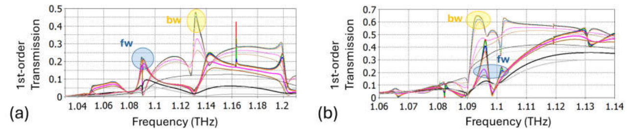
Figure 9 presents the exemplified results for free-standing asymmetric metagratings comprising a finite-thickness substrate, like the ones shown in Figure 1(c). In this case, the media above and below the metagrating are air, so that the f-ranges allowed for the appearance of higher diffraction orders are the same at the forward and backward illuminations, i.e., f1=f2. In turn, the f-ranges in which strong asymmetry in diffraction is achieved are rather accidental. Contrary to the metagratings placed at the interface, like in Figure 7 and Figure 8, strong diffractions occur when the noncorrugated side of the structure is illuminated, i.e., in the backward-illumination case. For instance, |t-1bw|=0.48 at f=1.1315 THz and |t1bw|/|t-1fw|in Figure 9(a). In Figure 9(b), strong asymmetry can be noticed at f=1.093 THz. In this case, |t-1bw(cross)|=0.61 and |t1bw(cross)|/|t-1fw(cross)|. As before, the magnitudes and contrasts are calculated at tand=0.00001. The condition still can be adopted in this case. The metastructures with a finite-thickness substrate can be said to be more sensitive to the variations in tand, but such high contrasts like in the case of semi-infinite low-e half-space were not obtained. One more case should be noted, i.e., |t1bw|≈|t-1fw| at f=1.0963 THz in Figure 9(b). It can be considered as anti-asymmetric case, because despite the strong structural asymmetry diffractions are close to being symmetric. Moreover, the rigorously symmetric case is expected to be achievable by means of geometrical parameter optimization.
5. Concluding Remarks
The results clarify how tanδ of the material used to make cylindrical resonators can affect achievable functionality of metasurfaces and metagratings. They show that strong local phase variations, i.e., phase jumps required for phase-gradient-enabled functionality, depend on the resonance choice, for a given value of tanδ. In turn, for each resonance, there is a critical value of tanδ, starting from which the desired jump is not achieved, so can be said to be an approximate condition for the phase-gradient related functionalities. The performed study makes evident the facts that tanδ pre-determines (i) which functionality requiring the full phase coverage can be achieved, and (ii) which range of the resonator radius and, hence, which fabrication accuracy are needed. Although the present study is dedicated to THz range, it provides useful guidelines for possible choice of materials within a much wider frequency range, including near-infrared and, probably, the visible. Metagratings enabling asymmetric diffractions are generally less sensitive to the variations in tanδ. Although diffraction efficiency and forward(backward)-to-backward(forward) diffraction contrast still depend on tanδ, the asymmetric functionality does not disappear. It follows from the results obtained that the transfer of the incident-wave energy into higher diffraction orders is possible for diverse materials, which can strongly differ in terms of permittivity and losses. In particular, the materials with , as expected to be typical for many composites and unbiased ferroelectrics at THz frequencies, can still be suitable for the use in diffractive metagratings. Interestingly, the asymmetric diffractions may create not only co-polarized but also cross-polarized components for higher diffraction orders. Asymmetric polarization manipulation will be a subject of one of our forthcoming studies. Besides, the features were detected that indicate the presence of BIC, which are also planned to study. Notably, the metastructure optimization in terms of efficiency and the resonance identification were beyond the scope. Nevertheless, this study clarifies which materials are appropriate and which ones are not appropriate for a selected functionality.
Author Contributions
All work in this paper is done by A.E.S.
Funding
The contribution of A.E.S. was funded by Narodowe Centrum Nauki, Project UMO-2020/39/I/ST3/02413.
Data Availability Statement
The original contributions presented in this study are included in the article. Further inquiries can be directed to the corresponding author.
Conflicts of Interest
The author declares no conflicts of interest.
Abbreviations
The following abbreviations are used in this manuscript:
| BIC | Bound States in the Continuum |
| PSHE | Photonic Spin Hall Effect |
| AT | Asymmetric Transmission |
References
- Chen, H. T.; Taylor, A. J.; Yu, N. A review of metasurfaces: physics and applications. Rep. Prog. Phys. 2016, 79, 076401. [Google Scholar] [CrossRef] [PubMed]
- Ding, F.; Pors, A.; Bozhevolnyi, S. I. Gradient metasurfaces: a review of fundamentals and applications. Rep. Prog. Phys. 2016, 81, 026401. [Google Scholar] [CrossRef] [PubMed]
- Yu, N.; Genevet, P.; Kats, M. A.; Aieta, F.; Tetienne, J. P.; Capasso, F.; Gaburro, Z. Light propagation with phase discontinuities: generalized laws of reflection and refraction. Science 2011, 334(6054), 333–337. [Google Scholar] [CrossRef] [PubMed]
- Grady, N. K.; Heyes, J. E.; Chowdhury, D. R.; Zeng, Y.; Reiten, M. T.; et al. Terahertz metamaterials for linear polarization conversion and anomalous refraction. Science 2013, 340(6138), 1304–1307. [Google Scholar] [CrossRef] [PubMed]
- Jiang, X.; Chen, H.; Li, Z.; Yuan, H.; Cao, L.; et al. All-dielectric metalens for terahertz wave imaging. Opt. Express 2018, 26(11), 14132–14142. [Google Scholar] [CrossRef] [PubMed]
- Khorasaninejad, M.; Capasso, F. Metalenses: Versatile multifunctional photonic components. Science 2017, 358(6367), eaam8100. [Google Scholar] [CrossRef] [PubMed]
- Kang, M.; Feng, T.; Wang, H.T.; Li, J. Wave front engineering from an array of thin aperture antennas. Opt. Express 2012, 20(14), 15882–15890. [Google Scholar] [CrossRef] [PubMed]
- Li, L.; Zhao, H.; Liu, C.; Li, L.; Cui, T. J. Intelligent metasurfaces: control, communication and computing. elight 2022, 2, 7. [Google Scholar] [CrossRef]
- Liu, S.; Cui, T. J. Concepts, working principles, and applications of coding and programmable metamaterials. Adv. Opt. Mater. 2017, 5, 1700624. [Google Scholar] [CrossRef]
- Abdulkarim, Y. I.; Mohanty, A.; Acharya, O. P.; Appasani, B.; et al. A review on metamaterial absorbers: microwave to optical. Front. Phys. 2022, 10, 893791. [Google Scholar] [CrossRef]
- Alaee, R.; Albooyeh, M.; Rockstuhl, C. Theory of metasurface based perfect absorbers. J. Phys. D. Appl. Phys. 2017, 50(50), 503002. [Google Scholar] [CrossRef]
- Heydari, E.; Sperling, J. R.; Neale, S. L.; Clark, A. W. Plasmonic color filters as dual-state nanopixels for high-density microimage encoding. Adv. Func. Mater. 2017, 27, 1701866. [Google Scholar] [CrossRef]
- Yin, X.; Ye, Z.; Rho, J.; Wang, Y.; Zhang, X. Photonic spin Hall effect at metasurfaces. Science 2013, 339(6126), 1405–1407. [Google Scholar] [CrossRef] [PubMed]
- Liu, Y.; Ke, Y.; Luo, H.; Wen, S. Photonic spin Hall effect in metasurfaces: a brief review. Nanophoton 2017, 6, 51–70. [Google Scholar] [CrossRef]
- Kang, M.; Liu, T.; Chan, C. T.; Xiao, M. Applications of bound states in the continuum in photonics. Nat. Rev. Phys. 2023, 5, 659–678. [Google Scholar] [CrossRef]
- Song, Q.; Odeh, M.; Zúñiga-Pérez, J.; Kanté, B.; Genevet, P. Plasmonic topological metasurface by encircling an exceptional point. Science 2021, 373(6559), 1133–1137. [Google Scholar] [CrossRef] [PubMed]
- Yan, Q.; Zhao, B.; Zhou, R.; Ma, R.; Lyu, Q.; et al. Advances and applications on non-Hermitian topological photonics. Nanophoton 2023, 12, 2247–2271. [Google Scholar] [CrossRef] [PubMed]
- Shou, Y.; Wang, D.; Wang, Y.; Huang, Q. K. L.; et al. Resonant and scattering exceptional points in non-Hermitian metasurfaces. npj Nanophoton 2025, 2, 29. [Google Scholar] [CrossRef]
- Serebryannikov, A. E.; Lakhtakia, A.; Ozbay, E. Thermally mediated transmission-mode deflection of terahertz waves by lamellar metagratings containing a phase-change material. Opt. Mater. Express 2024, 14, 745–758. [Google Scholar] [CrossRef]
- Sung, J.; Lee, G. Y.; Choi, C.; Hong, J.; Lee, B. Polarization-dependent asymmetric transmission using a bifacial metasurface. Nanoscale Horiz. 2020, 5(11), 1487–1495. [Google Scholar] [CrossRef] [PubMed]
- Ra’di, Y.; Sounas, D. L.; Alù, A. Metagratings: Beyond the limits of graded metasurfaces for wave front control. Phys. Rev. Lett. 2017, 119(6), 067404. [Google Scholar] [CrossRef] [PubMed]
- Liu, W.; Huang, L.; Ding, J.; Xie, C.; Luo, Y.; Hong, W. High-performance asymmetric optical transmission based on a dielectric–metal metasurface. Nanomaterials 2021, 11(9), 2410. [Google Scholar] [CrossRef] [PubMed]
- Shang, G.; Li, G.; Guan, C.; Zhao, W.; Li, H.; et al. Metasurface with directional-controlled asymmetric transmissions. Adv. Photon. Res. 2023, 4(5), 2200359. [Google Scholar] [CrossRef]
- Rodríguez-Ulibarri, P.; Beruete, M.; Navarro-Cía, M.; Serebryannikov, A. E. Wideband unidirectional transmission with tunable sign-switchable refraction and deflection in nonsymmetric structures. Phys. Rev. B 2013, 88(16), 165137. [Google Scholar] [CrossRef]
- Serebryannikov, A. E.; Ozbay, E. Isolation and one-way effects in diffraction on dielectric gratings with plasmonic inserts. Opt. Express 2009, 17, 278–292. [Google Scholar] [CrossRef] [PubMed]
- Habib, M.; Serebryannikov, A. E.; Caglayan, H.; Vandenbosch, G. A.; Ozbay, E. Connection of collimation, asymmetric beaming, and independent transmission-reflection processes in concentric-groove gratings supporting spoof surface plasmons. Plasmonics 2019, 14(3), 721–729. [Google Scholar] [CrossRef]
- Barkathulla, A.; Khan, F.; Lin, M.; Wang, Q.; et al. Demonstration of Asymmetric Electromagnetic Mode Conversion Induced by Spatial Symmetry Breaking in Linear Asymmetric Photonic Crystals. Laser Photon. Rev. 2026, 20(16), e02904. [Google Scholar] [CrossRef]
- Lockyear, M. J.; Hibbins, A. P.; White, K. R.; Sambles, J. R. One-way diffraction grating. Phys. Rev. E—Statistical Nonlinear Soft Matter Phys. 2006, 74(5), 056611. [Google Scholar] [CrossRef] [PubMed]
- Cicek, A.; Yucel, M. B.; Kaya, O. A.; Ulug, B. Refraction-based photonic crystal diode. Opt. Lett. 2012, 37(14), 2937–2939. [Google Scholar] [CrossRef] [PubMed]
- Chen, K.; Ding, G.; Hu, G.; Jin, Z.; Zhao, J.; et al. Directional Janus metasurface. Adv. Mater. 2020, 32, 1906352. [Google Scholar] [CrossRef] [PubMed]
- Chang, Y. C.; Lin, C. Y.; Su, H. T.; Wu, Y. C.; et al. Directionally asymmetric holographic imaging for arbitrary polarization states using Janus metasurfaces. Adv. Opt. Mater. 2025, e01546. [Google Scholar] [CrossRef]
- Yang, W.; Chen, K.; Dong, S.; Wang, S.; Qu, K.; et al. Direction-duplex Janus metasurface for full-space electromagnetic wave manipulation and holography. ACS Appl. Mater. Interf. 2023, 15, 27380–27390. [Google Scholar] [CrossRef] [PubMed]
- Hoorfar, A.; Perrotta, A. An experimental study of microstrip antennas on very high permittivity ceramic substrates and very small ground planes. IEEE Trans. Ant. Propag. 2001, 49(5), 838–840. [Google Scholar] [CrossRef] [PubMed]
- Savelev, R. S.; Filonov, D. S.; Petrov, M. I.; Krasnok, A. E.; Belov, P. A.; Kivshar, Y. S. Resonant transmission of light in chains of high-index dielectric particles. Phys. Rev. B 2015, 92(15), 155415. [Google Scholar] [CrossRef]
- Alù, A.; Engheta, N. Optical ‘shorting wires’. Opt. Express 2007, 15(21), 13773–13782. [Google Scholar] [CrossRef] [PubMed]
- Serebryannikov, A. E.; Usik, P. V.; Ozbay, E. Non-ideal cloaking based on Fabry-Perot resonances in single-layer high-index dielectric shells. Opt. Express 2009, 17(19), 16869–16876. [Google Scholar] [CrossRef] [PubMed]
- Lan, C.; Zhu, D.; Gao, J.; Li, B.; Gao, Z. Flexible and tunable terahertz all-dielectric metasurface composed of ceramic spheres embedded in ferroelectric/elastomer composite. Opt. Express 2018, 26(9), 11633–11638. [Google Scholar] [CrossRef] [PubMed]
- Zeng, Y.; Wang, W.; Ling, F.; Yao, J. Terahertz wave modulation properties of thermally processed BST/PZT ferroelectric photonic crystals. Photon. Res. 2020, 8(6), 1002–1010. [Google Scholar] [CrossRef]
- Dupas, C.; Guillemet-Fritsch, S.; Geffroy, P. M.; Chartier, T.; Baillergeau, M.; et al. High permittivity processed SrTiO3 for metamaterials applications at terahertz frequencies. Sci. Rep. 2018, 8(1), 15275. [Google Scholar] [CrossRef] [PubMed]
- Gaillot, D. P.; Croënne, C.; Lippens, D. An all-dielectric route for terahertz cloaking. Opt. Express 2008, 16(6), 3986–3992. [Google Scholar] [CrossRef] [PubMed]
- Djemmah, D. A.; Gourdonnaud, D.; Bouamrane, F.; Roux, J. F.; Geffroy, P. M.; Akmansoy, E. Impact of sintering conditions on the dielectric properties of TiO2 ceramics for metamaterialsapplications at terahertz frequencies. arXiv 2026, arXiv:2606.25930. [Google Scholar]
- Available online: https://www.3ds.com/products-services/simulia/products/cst-studio-suite/solvers/.
- Serebryannikov, A. E.; Cakmak, A. O.; Ozbay, E. Multichannel optical diode with unidirectional diffraction relevant total transmission. Opt. Express 2012, 20(14), 14980–14990. [Google Scholar] [CrossRef] [PubMed]
- Serebryannikov, A. E.; Fataliyev, K.; Cakmak, A. O.; Colak, E. Capability of dielectric resonator based meta-atoms with VO2 Components for switchable coding and wavefront-manipulating THz metasurfaces. Materials 2026, 19, 2449. [Google Scholar] [CrossRef] [PubMed]
- Rodríguez-Ulibarri, P.; Beruete, M.; Serebryannikov, A. E. One-way quasiplanar terahertz absorbers using nonstructured polar dielectric layers. Phys. Rev. B 2017, 96(15), 155148. [Google Scholar] [CrossRef]
- Gokkavas, M.; Gundogdu, T. F.; Ozbay, E.; Serebryannikov, A. E. Few-layer bifunctional metasurfaces enabling asymmetric and symmetric polarization-plane rotation at the subwavelength scale. Sci. Rep. 2024, 14(1), 13636. [Google Scholar] [CrossRef] [PubMed]
- Lee, W. S.; Kaltenecker, K.; Nirantar, S.; Withayachumnankul, W.; et al. Terahertz near-field imaging of dielectric resonators. Opt. Express 2017, 25(4), 3756–3764. [Google Scholar] [CrossRef] [PubMed]
- Liu, F.; Kwon, D. H.; Tretyakov, S. Reflectarrays and metasurface reflectors as diffraction gratings: A tutorial. IEEE Ant. Propag. Mag. 2023, 65(3), 21–32. [Google Scholar] [CrossRef]
- Maystre, D.R. Selected Papers on Diffraction Gratings; SPIE, 1993. [Google Scholar]
- Serebryannikov, A. E.; Alici, K. B.; Magath, T.; Cakmak, A. O.; Ozbay, E. Asymmetric Fabry-Perot-type transmission in photonic-crystal gratings with one-sided corrugations at a two-way coupling. Phys. Rev. A—Atomic Mol. Opt. Phys. 2012, 86(5), 053835. [Google Scholar] [CrossRef]
Figure 1.
Meta-atoms comprising cylindrical resonators made of a (very-)high-e material, which are: (a) separated from the back-side (lower-side) reflector by a low-e spacer, (b) placed atop the low-e half-space, and (c) placed atop the low-e finite-thickness substrate.
Figure 1.
Meta-atoms comprising cylindrical resonators made of a (very-)high-e material, which are: (a) separated from the back-side (lower-side) reflector by a low-e spacer, (b) placed atop the low-e half-space, and (c) placed atop the low-e finite-thickness substrate.

Figure 2.
Magnitude (left panel) and phase in degrees (right panel) for reflected wave in case of meta-atoms backed with a reflector at (a) rc=h=90 mm, Reec=9, ts=200 mm, p= 275 mm; (b) rc=h=110 mm, Reec=9, ts= 200 mm, p= 275 mm; (c) rc=h=50 mm, Reec=35, h= 50 mm, ts= 200 mm, p= 150 mm; at different values of tand: red lines – 0.00001, green lines – 0.0001, blue lines – 0.0005, orange lines – 0.001, violet lines – 0.005, brown lines – 0.01, black lines – 0.05, grey lines – 0.1.
Figure 2.
Magnitude (left panel) and phase in degrees (right panel) for reflected wave in case of meta-atoms backed with a reflector at (a) rc=h=90 mm, Reec=9, ts=200 mm, p= 275 mm; (b) rc=h=110 mm, Reec=9, ts= 200 mm, p= 275 mm; (c) rc=h=50 mm, Reec=35, h= 50 mm, ts= 200 mm, p= 150 mm; at different values of tand: red lines – 0.00001, green lines – 0.0001, blue lines – 0.0005, orange lines – 0.001, violet lines – 0.005, brown lines – 0.01, black lines – 0.05, grey lines – 0.1.
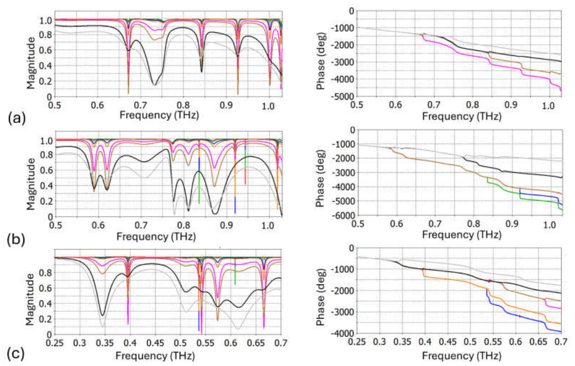
Figure 3.
Magnitude (left panel) and phase in degrees (right panel) for transmitted wave in case of meta-atoms with finite-thickness low-e substrate at (a) rc=h=110 mm, Reec=9, ts=200 mm, p= 275 mm; (b) rc=h=50 mm, Reec=35, ts=200 mm, p=150 mm, for different values of tand: red lines – 0.00001, green lines – 0.0001, blue lines – 0.0005, orange lines – 0.001, violet lines – 0.005, brown lines – 0.01, black lines – 0.05, grey lines – 0.1.
Figure 3.
Magnitude (left panel) and phase in degrees (right panel) for transmitted wave in case of meta-atoms with finite-thickness low-e substrate at (a) rc=h=110 mm, Reec=9, ts=200 mm, p= 275 mm; (b) rc=h=50 mm, Reec=35, ts=200 mm, p=150 mm, for different values of tand: red lines – 0.00001, green lines – 0.0001, blue lines – 0.0005, orange lines – 0.001, violet lines – 0.005, brown lines – 0.01, black lines – 0.05, grey lines – 0.1.
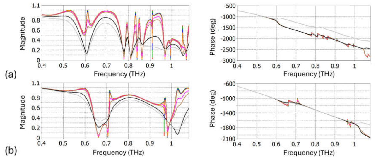
Figure 4.
Magnitude (left panel) and phase in degrees (right panel) for transmitted wave in case of meta-atoms comprising semi-infinite low-e half-space at (a) rc=h=110 mm, Reec=9, p=275 mm; (b) rc=h=50 mm, Reec=35, p= 150 mm, for different values of tand: red lines – 0.00001, green lines – 0.0001, blue lines – 0.0005, orange lines – 0.001, violet lines – 0.005, brown lines – 0.01, black lines – 0.05, grey lines – 0.1.
Figure 4.
Magnitude (left panel) and phase in degrees (right panel) for transmitted wave in case of meta-atoms comprising semi-infinite low-e half-space at (a) rc=h=110 mm, Reec=9, p=275 mm; (b) rc=h=50 mm, Reec=35, p= 150 mm, for different values of tand: red lines – 0.00001, green lines – 0.0001, blue lines – 0.0005, orange lines – 0.001, violet lines – 0.005, brown lines – 0.01, black lines – 0.05, grey lines – 0.1.
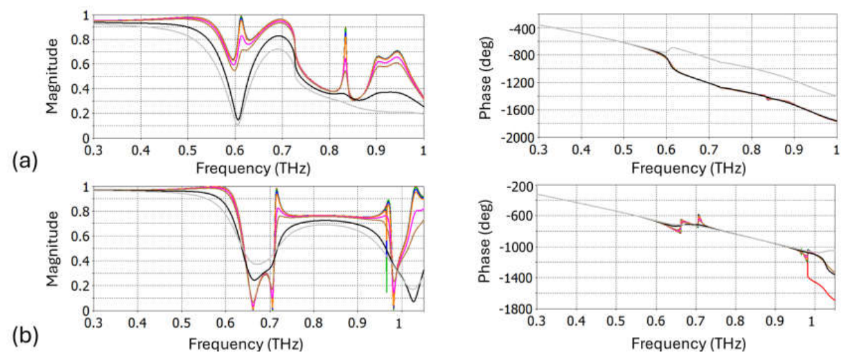
Figure 5.
Phase of reflected wave on (f,rc)-plane for the structures with back-side reflector at rc=h=90 mm, Reec=9, ts=200 mm, p= 275 mm: (a) tand = 0.0005, (b) tand = 0.005, (c) tand = 0.05. Dotted white lines indicate the ranges of rc within which the full phase range is achieved.
Figure 5.
Phase of reflected wave on (f,rc)-plane for the structures with back-side reflector at rc=h=90 mm, Reec=9, ts=200 mm, p= 275 mm: (a) tand = 0.0005, (b) tand = 0.005, (c) tand = 0.05. Dotted white lines indicate the ranges of rc within which the full phase range is achieved.
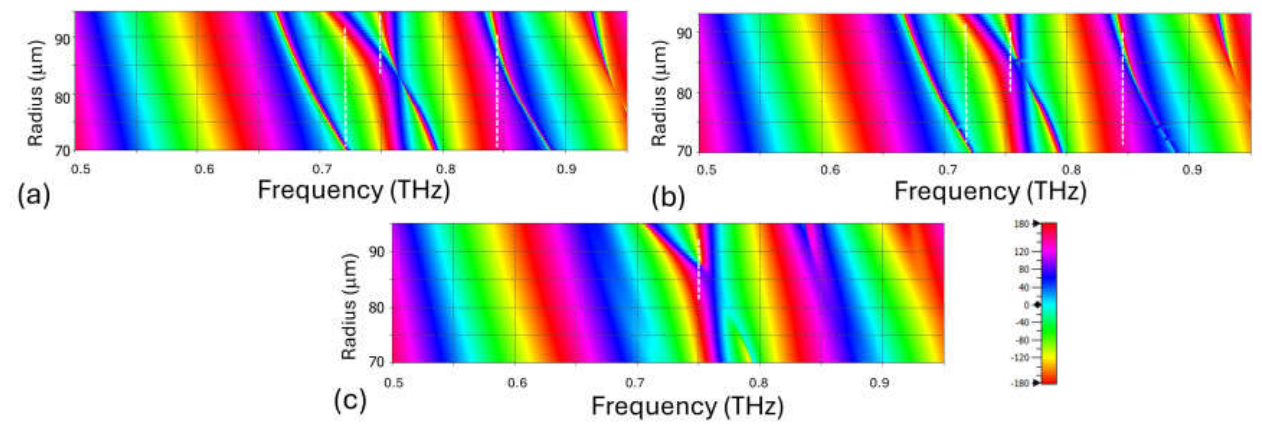
Figure 6.
Phase of reflected wave on (f,rc)-plane for the structures with back-side reflector at rc=h=50 mm, Reec=35, ts=200 mm, p=150 mm: (a) tand = 0.0005, (b) tand = 0.05. Dotted white lines indicate the ranges of rc suitable to cover the full phase range.
Figure 6.
Phase of reflected wave on (f,rc)-plane for the structures with back-side reflector at rc=h=50 mm, Reec=35, ts=200 mm, p=150 mm: (a) tand = 0.0005, (b) tand = 0.05. Dotted white lines indicate the ranges of rc suitable to cover the full phase range.

Figure 7.
Magnitude of (a,c,d) -order co-polarized transmitted wave and (b) -order co-polarized reflected wave for meta-atoms comprising semi-infinite low-e half-space at (a,b) rc=h=90 mm, Reec=9, ts=200 mm, p= 275 mm; (c) rc=h=110 mm, Reec=9, ts=200 mm, p= 275 mm; (d) rc=h=90 mm, Reec=35, ts=200 mm, p= 275 mm, for different values of tand: red lines – 0.00001, green lines – 0.0001, blue lines – 0.0005, orange lines – 0.001, violet lines – 0.005, brown lines – 0.01, black lines – 0.05, grey lines – 0.1; thick lines – forward-case illumination (denoted by fw), thin lines – backward-case illumination (denoted by bw).
Figure 7.
Magnitude of (a,c,d) -order co-polarized transmitted wave and (b) -order co-polarized reflected wave for meta-atoms comprising semi-infinite low-e half-space at (a,b) rc=h=90 mm, Reec=9, ts=200 mm, p= 275 mm; (c) rc=h=110 mm, Reec=9, ts=200 mm, p= 275 mm; (d) rc=h=90 mm, Reec=35, ts=200 mm, p= 275 mm, for different values of tand: red lines – 0.00001, green lines – 0.0001, blue lines – 0.0005, orange lines – 0.001, violet lines – 0.005, brown lines – 0.01, black lines – 0.05, grey lines – 0.1; thick lines – forward-case illumination (denoted by fw), thin lines – backward-case illumination (denoted by bw).
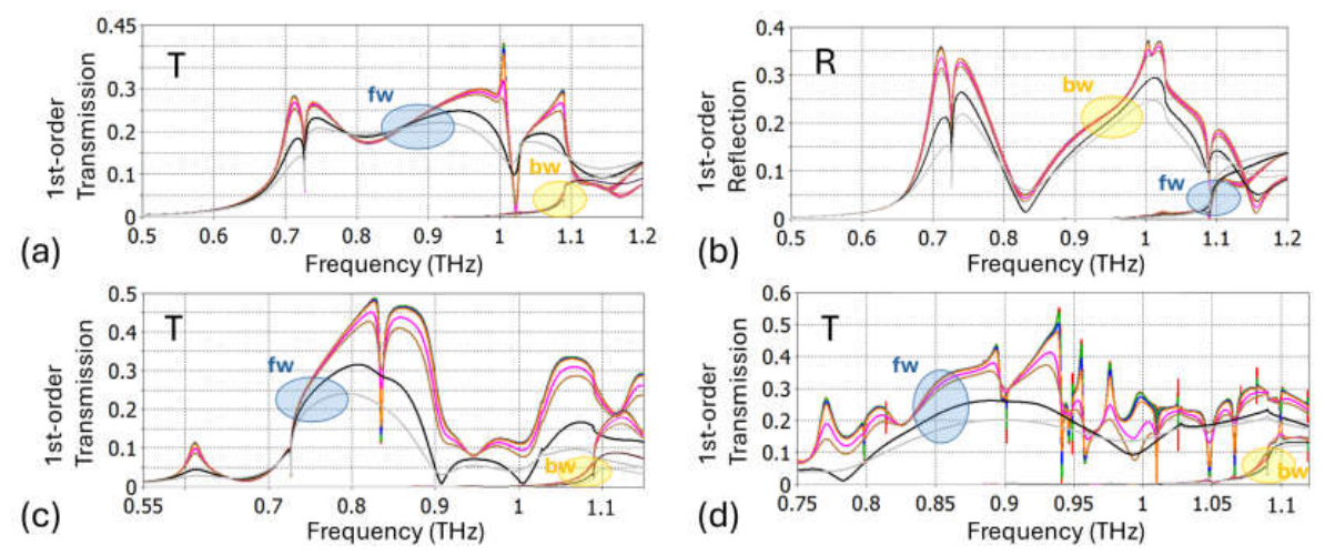
Figure 8.
Magnitude of -order cross-polarized transmitted wave for meta-atoms with semi-infinite low-e half-space at (a) rc=h=90 mm, Reec=9, p=275 mm; (b) rc=h=110 mm, Reec=9, p=275 mm, for different values of tand: red lines – 0.00001, green lines – 0.0001, blue lines – 0.0005, orange lines – 0.001, violet lines – 0.005, brown lines – 0.01, black lines – 0.05, grey lines – 0.1; thick lines – forward-case illumination (denoted by fw), thin lines – backward-case illumination (denoted by bw).
Figure 8.
Magnitude of -order cross-polarized transmitted wave for meta-atoms with semi-infinite low-e half-space at (a) rc=h=90 mm, Reec=9, p=275 mm; (b) rc=h=110 mm, Reec=9, p=275 mm, for different values of tand: red lines – 0.00001, green lines – 0.0001, blue lines – 0.0005, orange lines – 0.001, violet lines – 0.005, brown lines – 0.01, black lines – 0.05, grey lines – 0.1; thick lines – forward-case illumination (denoted by fw), thin lines – backward-case illumination (denoted by bw).
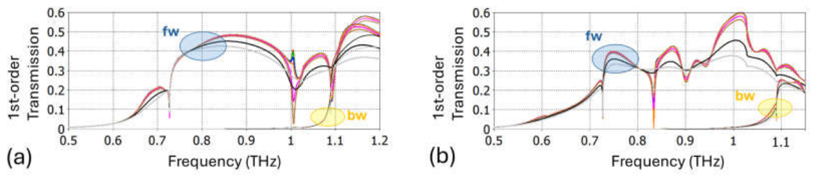
Figure 9.
Magnitude of (a) -order co-polarized transmitted wave and (b) -order cross-polarized transmitted wave for meta-atoms with low-e finite-thickness substrate at (a) rc=h=90 mm, Reec=9, ts=200 mm, p=275 mm; (b) rc =h=90 mm, Reec =35, ts=200 mm, p=275 mm; for different values of tand: red lines – 0.00001, green lines – 0.0001, blue lines – 0.0005, orange lines – 0.001, violet lines – 0.005, brown lines – 0.01, black lines – 0.05, grey lines – 0.1; thick lines – forward-case illumination (denoted by fw), thin lines – backward-case illumination (denoted by bw).
Figure 9.
Magnitude of (a) -order co-polarized transmitted wave and (b) -order cross-polarized transmitted wave for meta-atoms with low-e finite-thickness substrate at (a) rc=h=90 mm, Reec=9, ts=200 mm, p=275 mm; (b) rc =h=90 mm, Reec =35, ts=200 mm, p=275 mm; for different values of tand: red lines – 0.00001, green lines – 0.0001, blue lines – 0.0005, orange lines – 0.001, violet lines – 0.005, brown lines – 0.01, black lines – 0.05, grey lines – 0.1; thick lines – forward-case illumination (denoted by fw), thin lines – backward-case illumination (denoted by bw).
Disclaimer/Publisher’s Note: The statements, opinions and data contained in all publications are solely those of the individual author(s) and contributor(s) and not of MDPI and/or the editor(s). MDPI and/or the editor(s) disclaim responsibility for any injury to people or property resulting from any ideas, methods, instructions or products referred to in the content. |
© 2026 by the author. Licensee MDPI, Basel, Switzerland. This article is an open access article distributed under the terms and conditions of the Creative Commons Attribution (CC BY) license.
Copyright: This open access article is published under a Creative Commons CC BY 4.0 license, which permit the free download, distribution, and reuse, provided that the author and preprint are cited in any reuse.