

Submitted:
31 August 2026
Posted:
01 September 2026
You are already at the latest version
Abstract
Miniaturisation of artificial organs to an implantable form factor is one of the great challenges in biomedical engineering. Most patients with end-stage kidney failure depend on dialysis, yet dialysis remains burdensome. An implantable artificial kidney would be a paradigm shift that would largely replace the need for dialysis. By coupling the joint constraints on hemocompatibility, hemodynamics, and epithelial transport to boundary conditions, such as the pressure and shear stress imposed by the human body, we show that: (i) blood compatibility requires centimetre-scale blood-distribution manifolds and preferably endothelialised channels; (ii) concentration polarisation and hemoconcentration limit filtration performance, causing diminishing returns from higher membrane permeability; (iii) hemodynamics and packing constraints drive local channels toward capillary-scale dimensions; and (iv) proximal-tubule-only architectures cannot satisfy sodium, potassium, phosphate, and water balance without shifting a large homeostatic burden to the patient. This necessitates multiple epithelial modules requiring ∼ 1.15 m2 of active surface area and ∼ 250 layers and makes near-kidney proximal-tubule transport capacity a prerequisite for geometric feasibility. Together, our results show that the minimally viable artificial kidney is still constrained to a kidney-scale, macro-to-micro architecture. This conclusion applies not only to synthetic scaffold-based designs, but also to biological and hybrid strategies in which cells participate in architecture formation, since all such routes must satisfy the same coupled requirements.
Keywords:
artificial organs
; artificial kidney
; hemodynamics
; hemocompatibility
; nephrology
1. Introduction
Transport organs such as the kidney are essential for homeostasis in our natural environment. Over the course of evolutionary history, there has been considerable selection pressure leading to convergence towards high surface area, small local transport scales, and efficient hierarchical routing. This convergence is driven by the fundamental physics of solute transport and by the need for high spatial efficiency within the organ (West et al. 1997,West et al. 1999). This is particularly relevant to organs such as the kidney, lung, placenta, and gut, which rely, in part, on diffusive transport of key solutes. Efforts to (partly) replace failing organs have led to the development of extracorporeal machines that are orders of magnitude larger (cubic metres versus cubic centimetres) than the organs they aim to replace. Therefore, these conventional systems are neither portable nor implantable. As a consequence, other than transplantation, organ-replacement therapy is typically intermittent and mostly stationary (Himmelfarb et al. 2020,Ramada et al. 2023,Wieringa et al. 2025).
This study uses the artificial kidney as a case study to evaluate the fundamental principles underpinning a broader class of implantable artificial transport organ systems, such as the artificial lung and placenta. The artificial kidney is chosen because of the intense ongoing efforts to replace dialysis. Approximately 800,000 patients in Europe and North America alone depend on dialysis (United States Renal Data System 2024,Hoekstra et al. 2026), of whom only a minority are eligible for transplantation. In addition to this scale, the burden is also very large, with even young patients facing a 43-year reduction in life expectancy compared with the general population for the cohort aged 18-23 years (UK Renal Registry 2021). Despite this, the paradigm of hemodialysis has remained largely unchanged for the past 50 years (Wieringa et al. 2020).
An implantable artificial kidney is sought as a paradigm shift that would largely replace dialysis. For the purposes of this study, the artificial kidney is defined as a fully implantable, autonomous device driven by the heart as the blood pump, in which, at a minimum, uremic toxin removal and sodium, potassium, phosphate, and water handling can be regulated by the implant. This autonomous nature separates the artificial kidney from a broader class of renal-assist devices that are mentioned only briefly. Attempts to create such an artificial kidney have ranged from fully biological approaches using recellularised kidneys, fetal tissues, or organoids (Song et al. 2013,Huang et al. 2025,Yokote et al. 2015) to more engineering-based approaches aiming to build a biohybrid implant (Fissell et al. 2009,Kim et al. 2023). The biohybrid implant utilises a hemofilter coupled with a bio-interface (to be called "bioreactor" from hence) housing renal epithelial cells to recapitulate key excretion and reabsorption functions. The former approaches currently remain at the submillimetre scale, with limited or absent higher-order hierarchy, cellular maturity, vascularisation, and urinary drainage (Huang et al. 2025,van den Berg et al. 2025). The engineering approaches have assessed the feasibility of individual elements via animal models (Kim et al. 2023,Moyer et al. 2023). However, these efforts have largely remained at the subsystem level (either hemofilter or the bioreactor only), with the primary research questions concerning membrane permeability, hemocompatibility, and in vitro cell function, rather than the whole-system realities that ultimately constrain subsystem optimisation.
In this study, we use transport-theoretic analysis and mathematical modelling at a geometric level to show that, even under favourable assumptions such as a large implantation volume, peritoneal dialysis equivalent clearance, and native epithelial like water reabsorption, the artificial kidney requires kidney-scale architecture and integration. As represented schematically in Figure 1, a functioning artificial kidney would need to reproduce key architectural features of the organ it aims to replace, such as channel size, interface thickness, and macro-to-micro hierarchy, potentially in a monolithic form. These requirements apply to both purely biological approaches (i.e., growing a kidney biologically) and hybrid engineering approaches. This form invariance is driven by the coupled constraints imposed by hemocompatibility, hemodynamics, transport, and spatial packing within an implantable envelope. More broadly, the same logic is likely to extend to other organ-replacement technologies that must perform transport. We first analyse these constraints at the most fundamental level of surface-area-to-volume ratio, perfusability, and blood distribution before considering membrane filtration, epithelial reabsorption, and implantable packing in the specific case of the artificial kidney.
2. Results
2.1. Coupled Constraints on the Local Scale
Surface area, A, volume, V, and channel height, h, are key parameters that determine the performance and size of an artificial organ. Here, the surface-area-to-volume ratio scales as
where h is the characteristic channel height. The order-of-magnitude difference between the channel height in native organs () and that in extracorporeal dialysers and oxygenators () partially explains why the former are implantable, whereas the latter are not.
In addition to packing efficiency, small channel heights also increase diffusive mass transfer.
where is the mass-transfer coefficient. The scaling in Equation (2) is used here as the local mass-transfer rate limit. In the kidney, the small channel height allows greater back-diffusion of plasma proteins from the filtration surface (on the capillary side) into the bulk, thereby limiting concentration polarisation and enabling higher filtration than would be possible with larger channels (Section 2.4).
As the channel dimension shrinks, the length L must increase proportionally to maintain a large exchange area. This means that a high slenderness ratio is favoured, where .
Large , however, comes at the cost of available pressure head , which, for an implantable artificial transport organ that must operate without an external pump, is capped by the heart at mmHg across an arterial-venous connection. In contrast, the wall shear stress throughout the device must be co-optimised to remain within the physiological range of 1-5 Pa (Roux et al. 2020,Zhou et al. 2023). For a parallel-slit geometry, in which the blood channels are rectangular slits that are much wider than they are high, the pressure drop along the channel is (see derivation in Section 5.1)
For mmHg and Pa, the required hydraulic length for a given channel height is
Hence, for , 20, and , the required lengths are , , and cm, respectively, simply to avoid the excessive shear that would otherwise be caused by the systemic pressure. These channels are similar to the efferent arteriole of the glomerulus, which is (Neal et al. 2018). This already forces small, capillary-like channel heights. Thus, the pressure/shear constraint fixes the required slenderness ratio , while implantability, packing efficiency, and transport all favour smaller channel dimensions h.
If the exchanger is arranged as a planar slit-stack of fixed span W, then for fixed slenderness
the exchange area contributed by one slit scales as
The factor 2 arises from the presence of two exchange surfaces, one on either side of the channel. Thus, in two dimensions (2D), as h is reduced, the area contributed by each unit decreases linearly. To recover the required total area , the number of parallel units, N, must therefore increase with
This means that the number of layers increases in inverse proportion to channel height.
If the available per-layer pitch is p, then, for a fixed device thickness , the per-layer pitch becomes
If interfaces between fluidic layers, such as membranes and cells, cannot scale with h as strongly, then layers cannot become thin enough to be housed within the total available thickness.
Although high slenderness ratios are needed to pack enough device surface area inside the available implantation space, there is a blood compatibility penalty incurred. This arises from the increased risk of clotting. A Hellums-based engineering metric relevant to a continuously circulating platelet in an implant gives the shear-activation dose as (Feaugas et al. 2023)
Here, is the time spent in the channel, is the wall shear stress, and is the dynamic viscosity of blood, assumed constant at 0.0035 Pa s (see derivation in Section 5.1). The resulting dose from the required slenderness of is approximately one order of magnitude above the conventional Hellums limit. As a further example, a typical hemodialysis fibre used for intermittent treatment may have a length of 20 cm and a diameter of . For a circular fibre the same dose becomes
which gives
Because this value is above the shear-activation metric, it indicates a clotting risk in conventional dialysers. Indeed, in a micro-CT study of used hemodialysers, the post-dialysis fraction of open fibres was , and fibre patency was not significantly associated with anticoagulation dose (Eloot et al. 2023). This degree of functional loss would be unacceptable for an implantable artificial organ intended to operate continuously for years. This is further compounded by a potential mechanism for cascading failure during flow distribution and by the fact that the shear criterion is likely an underestimate, as it does not account for surface-based activation, which is likely to be more important in exchange beds with a high surface-area-to-volume ratio.
The scale of hemocompatibility required therefore likely forces man-made coatings to be endothelium-like with comparable antithrombotic function and longevity to a living endothelium, or indeed a living endothelium itself. Such a synthetic or hybrid surface has currently not been demonstrated for this class of device and remains an open scientific problem, especially when compared with more traditional antifouling surface coatings, which remain limited in longevity even for simple vascular grafts (Halbert et al. 2020).
2.2. Blood-distribution Manifold
The previous sections established the local dimensional scales required for an artificial transport organ. Small blood channels are favoured for spatial and transport efficiency, and perfusability within an implantable envelope. However, there is also an axial-length penalty associated with routing blood into such a structure, this subtracts from the total implantation budget.
Blood must be routed from the near-centimetre-scale artery of anastomosis to the micron-scale local blood channels of the exchange bed. For blood compatibility, and particularly if a living antithrombotic endothelium is to be maintained, the flow should remain physiologically attached and without large variations in wall shear. Blood therefore cannot be expanded rapidly into the full hydraulic area. In the body, this problem is solved by a hierarchical three-dimensional vascular tree that usually follows an approximate Murray’s law (Painter et al. 2006). The vasculature expands the flow through repeated branching into progressively smaller daughter vessels, thereby supporting the boundary layer. In Murray’s Law, the parent and daughter channels are related by the equation
We evaluate the plausible axial penalty for a 2D slit-stack-type exchanger using two models with increasing fidelity, as shown in Figure 2. Model A is a continuum model of branching that can be specified analytically (see derivation in Section 5.4). We start at the root, where is the dimensionless surviving flow fraction. A single global curve from this root to the periphery of the exchange bed is then constructed. This curve is parametrised by , which is a normalised x-axis progress variable in the domain , such that , where X is the axial length of the manifold. As it traverses from the root to the periphery, branching is modelled by imposing a continuous decrease in flow along this curve. Moreover, any point along the curve also has a radius (and thus an area) attributable to it. The radius/characteristic length then decreases in proportion to the flow as , so that wall shear stress can remain constant throughout the manifold. We can therefore refer to it as a stream tube, as opposed to a stream curve or line. The model can thus be seen as a smeared branching hierarchy. The curvature of this curve and the deceleration of the flow must remain small enough for the boundary layer to remain attached. This is specified by the curvature and deceleration severity criteria.
Here, U, in m/s, is the local mean flow velocity along the stream tube; s is the arc-length coordinate; , in m, is the corresponding differential path length; ℓ, in m, is the local characteristic channel length scale (hydraulic diameter); and is the dimensional geometric curvature of the stream-tube centreline, in . The quantities and are therefore dimensionless severity criteria: measures the velocity-decay severity over one local length scale, while measures the centreline-curvature severity over one local length scale.
At very small expansion lengths, the flow must be routed at an almost 90-degree angle to reach the exchanger face. Such severe changes in flow direction would cause detachment. There is therefore a minimum axial length along the x-axis that the manifold must have to satisfy the curvature and velocity criteria. The analytical model provides an approximation of this lower axial bound based on the assumption of a single global routing curve to the exchanger face. The single-curve routing, however, also enforces on the peripheral nodes the curvature constraint that is strictest at the root. This means that the axial length is larger than it would be if a discrete hierarchy were used.
Model B forms a discrete hierarchical model in which the manifold splits the axial length into a number of branching stages. Here, multiple parametric curves specify the route from the root to the periphery, one at every stage between discrete branching points. This staged routing greatly increases the allowable curvature in the distal segments.
The range of was taken as 0.2-1.7. The upper end of 1.7 was chosen because, if the lumen wall thickness is , where d is the inner diameter of the channel, then, for , the channel wall folds through itself. In arteries with diameters similar to the root scale, the approximate is usually 0.7 (see Section 5.4), indicating that physiology operates well below this geometric limit. The range for was set at 0.02-0.2. Above 0.2, the transition length is too short for the flow to develop, causing low-shear zones at bifurcations. Moreover, values above 0.2 do not influence the axial length, as becomes the dominant factor (see Section 5.4).
The predicted axial lengths for both models are shown in Figure 3a. The range of manifold lengths within the geometrically plausible curvature criterion is 6-1.6 cm for model A and 4-1.1 cm for model B. The analytical formulation has a longer axial length because distribution from the root to the terminal node is parametrised by a single curve that inherits the most severe curvature penalty imposed at the root, whereas, for discrete model B, the curvature can be increased as the hydraulic scale decreases. The discretisation advantage is clear from Figure 3b, where the minimum axial length increases towards the analytical minimum with a smaller number of branches. At a still higher number of branches, this effect shows diminishing returns. This is because most of the routing cost is incurred near the root, where the curvature penalty is high because of the large flow and characteristic length.
Our analysis, although not proof of a globally optimal lower bound, indicates that the blood-distribution manifold, even under favourable assumptions, incurs a centimetre-scale axial penalty when perfusing a 2D surface, with a minimum axial length of 1.1 cm required to avoid a geometric curvature singularity. The more likely physiological axial length using is cm (see Section 5.4 for an estimate of physiological ), with manufacturability potentially driving this to longer lengths. Two manifolds, one for arterial perfusion and the other for venous return, would create a routing penalty of 4-6 cm, which is a very significant portion of the implantation envelope. The remaining space would have to be split between hemofiltration and reabsorption.
2.3. Reabsorption: Water and Electrolyte Homeostasis
The coupled constraints identified in Section 2.1 become explicitly clear in the artificial kidney. Here, there are two specialised exchange surfaces: one for reabsorption to enable water/solute homeostasis and the other for hemofiltration. In vivo, blood is first filtered in the glomeruli to create iso-osmotic pre-urine, meaning that small solutes are at approximately plasma concentration. In addition to preserving sufficient clearance of waste molecules, a large part of the ultrafiltrate (water and useful solutes) must then be reabsorbed via the subsequent segments of the tubule. A self-contained, autonomous artificial kidney must perform a similar function to maintain homeostasis.
Kt/V is a useful clinical dialysis-adequacy metric based on urea clearance. It can therefore be taken as a simple engineering criterion. Quality of life has been found to be strongly associated with increased Kt/V up to 1.6, beyond which no further increase occurs Wieringa et al. (2024). Therefore, the minimum urea clearance needed by the artificial kidney is
For a urea clearance of approximately , this deliberately favourable requirement can be met for a reasonably sized patient. This threshold is a best-case modelling floor, below the standard minimum values used in KDOQI guidance for non-thrice-weekly dialysis schedules (National Kidney Foundation 2015).
One possible version of the artificial kidney uses only the proximal tubule epithelial cells (PTECs) for reabsorption. In the native proximal tubule (PT), 65% of the filtered water and only about 50% of filtered urea is reabsorbed (Zhuo and Li 2013,Bankir and Yang 2012). A PT-only reabsorption must therefore generate an ultrafiltration rate of
where is the water-recovery fraction, is the effective water-coupling coefficient, which in the native PT is , and is the ultrafiltration rate. This creates a direct coupling between water recovery, urine output, and urea clearance:
Using Equations (15)–(17), and assuming a maximum urine outflow of , , and thus , would be 0.7466 and , respectively. This is a much higher water recovery burden than in the native proximal tubule. The situation becomes more severe if rises above the assumed value, as would be expected once urea becomes more concentrated in the lumen and back-diffusion increases (Layton et al. 2016). A PT-only architecture therefore faces an unfavourable trade-off between water recovery and urea clearance.
A PT-only architecture faces a harder problem in maintaining electrolyte balance. In the PT, sodium and potassium are reabsorbed iso-osmotically with respect to plasma, in proportion to water (Zhuo and Li 2013). Phosphate is reabsorbed in a higher proportion via NaPi cotransporters, with 85% of filtered phosphate being reabsorbed in the PT (Blaine et al. 2015). For a PT-only device with a daily urine output of , losses of key solutes are given in Table 1:
In this simple model, the daily sodium loss is equivalent to an intake of 40.39 g/day of table salt (NaCl) and, because the PT-only device does not provide net acid excretion/new bicarbonate generation, 12.6 g/day of baking soda (NaHCO3). This level of salt burden cannot be compensated easily with supplementation. Moreover, the iso-osmotic loss of fluid would mean that thirst is triggered only by significant hypovolaemia, forcing patients to regulate their volume status consciously.
The potassium excretion is a factor lower than prescribed maximum potassium intake in maintenance hemodialysis (Wouda et al. 2021), meaning that the patient must adhere to stricter dietary restrictions at the risk of hyperkalaemia.
For phosphorus, there would be little excretion. If we assume native-like kidney reabsorption, total excretion at the clearance of the device would be <5.3 mmol/day. However, the PT-only architecture relies more heavily on PT recovery than the kidneys do. This means that fractional reabsorption would be higher than 85%, which is why total excretion would be mmol/day, with an uncertain lower bound. This would require the ingestion of pharmaceutical agents that can reduce phosphorus reabsorption Clerin et al. (2020) or genetic engineering of the PT to reabsorb less phosphorus. Alternatively, or in combination with these approaches, intestinal phosphate absorption could be reduced using phosphate binders or inhibitors of intestinal phosphate absorption.
Reliance on patient behaviour to maintain fluid and electrolyte homeostasis would impose a substantial self-management burden. This means that the artificial kidney requires three segments: a PT segment for bulk isotonic reabsorption, a thick ascending limb (TAL) analogue for additional NaCl recovery in a water-impermeable segment, and a distal tubule (DT) analogue for potassium secretion.
If one assumes native operational capacity (see Section 5.5) at the specified water-recovery ratio, ultrafiltration rate and urine output, the required cell-laden areas are given in Table 2:
For the expression of transporters needed for water reabsorption, there must be fluidic torque and thus shear on the epithelial microvilli (Wang et al. 2017). In the artificial kidney, the hydraulic diameter of the filtrate channel along the reabsorbing part of the PT module must therefore decrease as water leaves to keep the epithelial shear approximately constant. Likewise, on the blood side, the channel height must increase slightly along the same segment; otherwise, a higher wall shear stress must be accepted.
Epithelial shear stresses in the range of approximately are commonly applied to in vitro proximal-tubule models Homan et al. (2016); this range is therefore considered in fig:filtratechanneldimvsLptc. fig:filtratechanneldimvsLptc shows that, for the desired fluidic-shear range, channel dimensions are for . This means that the channels approach a few multiples of an epithelial-cell height, potentially creating substantial recellularisation difficulties depending on the exact shear set point.
Figure 4.
(a) Filtrate-channel dimensions as a function of the designed total PT-module length at different filtrate-side shear stresses. (b) Blood-channel dimensions as a function of PT-module length at different hydrostatic gradients. Dashed and solid lines indicate outlet and inlet channel heights, respectively.
Figure 4.
(a) Filtrate-channel dimensions as a function of the designed total PT-module length at different filtrate-side shear stresses. (b) Blood-channel dimensions as a function of PT-module length at different hydrostatic gradients. Dashed and solid lines indicate outlet and inlet channel heights, respectively.
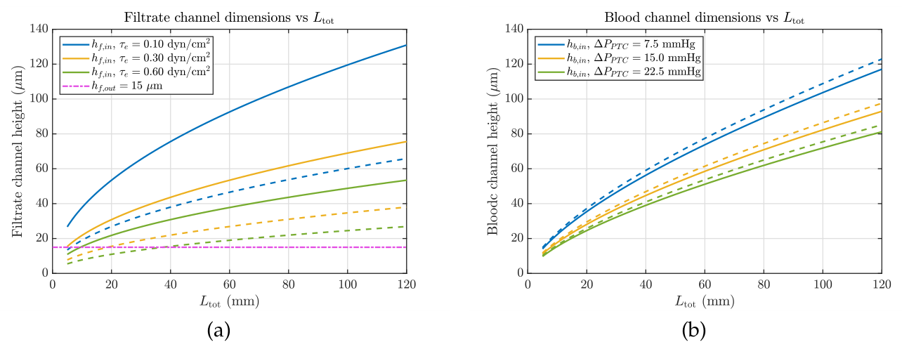
For the blood side, we take a range of PT-inlet hydrostatic pressures, expressed equivalently as a pressure drop, along the active reabsorbing segment, and assume that this drop is dissipated monotonically over the. We analyse a range of 5 to . At the upper end of this range, the blood-side hydrostatic pressure approaches the post-filtration oncotic driving force, such that net water reabsorption can be strongly suppressed. Filtrate-side hydraulic pressure is assumed to be negligible. It could, in principle, be generated but would counteract hemofiltration. Here, channel dimensions are for . These channels can likewise create difficulties for recellularisation because they are only a few multiples larger than the suspension size of endothelial cells (if an endothelium is required).
2.4. Hemofiltration
One of the primary areas of focus in artificial-kidney research has been the fabrication of ultrahigh-permeability membranes with a molecular-size cut-off at kD so that they do not leak albumin. The ambition is to utilise their high hydraulic permeability and thereby allow high ultrafiltration rates in a very small, implantable form factor.
However, hemofiltration performance is strongly limited by concentration polarisation (Deen et al. 1974). This occurs when innate permeability is counteracted by rising oncotic back-pressure as rejected plasma proteins create a boundary layer on the membrane surface. This boundary layer is determined by the equilibrium between rejected species arriving at the membrane and diffusing back into the bulk. We developed a one-dimensional (1D) model of ultrafiltration, see Supplementary Information Section 5.6.1, to assess the roles of channel height h, innate membrane permeability given by its buffer permeability , and filtration length .
In our model, the local ultrafiltration (UF) flux through one permeable wall is governed by
where is the hydraulic permeability in buffer and is the oncotic pressure as a function of plasma protein concentration at the wall, , given in g/dL.
Concentration polarisation was represented via the film-theory relation (Deen et al. 1974,van den Berg et al. 1989)
where is the bulk protein concentration and is the mass-transfer coefficient. Therefore, combining Equations (18) and (19), the nonlinear implicit equation that was solved is
Here, F is the unit-conversion factor .
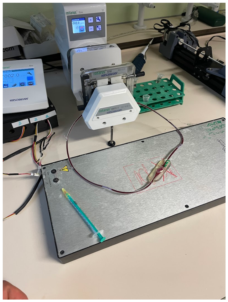
We first validated the model with a hemofiltration experiment using a 13-mm-diameter anodic aluminium oxide membrane with a blood-channel height of and a blood-flow rate of . fig:hemofiltera shows a good match with the experimental permeate-flow rate. The model overshoots at higher transmembrane pressures (TMPs), likely because of compaction of the cell layer, which is not accounted for in the model.
To extrapolate the findings to a full-scale device, we assumed the optimistic case of unchanged blood viscosity, a fractional clearance of 20%, and acceptable shear inside the filtration channel. The ultrafiltration target was set to , as computed in Section 2.3. The width was set to 10 cm, the same as that of the bioreactor. The number of layers was adjusted such that the wall-shear criterion Pa could be met.
fig:hemofilter shows the result of this simulation. The primary finding is that the innate permeability of the membrane has relatively little influence on the required area. A change in membrane permeability by a factor of 30 translates to an area reduction of only (Figure 5b). Moreover, as the number of layers increases at a fixed blood-channel height (Figure 5c), the axial length required for hemofiltration decreases significantly to below the centimetre scale, with area requirements decreasing by up to one order of magnitude. Lastly, the area needed for filtration is a strong function of channel height, with greater channel heights requiring a much larger active filtration area and subsequently taking more axial space (Figure 5d).
Together, the results indicate that increasing innate membrane permeability has diminishing returns and that, even for membranes with low permeability, hemofiltration is not an important bottleneck for whole-device feasibility, as the geometric constraints on the bioreactor are more severe.
2.5. Geometric Feasibility Space for the Artificial Kidney
Given the required area and channel dimensions, the feasibility space for the 2D slit-stack artificial kidney can now be determined. To avoid biasing the analysis towards infeasibility, the feasibility space was evaluated under the favourable assumptions of low clearance, as noted in Section 2.3; epithelial-limited rather than sink-limited recovery; final filtrate-channel dimensions smaller than the cell scale; and a large implantation envelope of 10 cm axial length, 10 cm width, and 6 cm thickness ( kidney volume). Even before the inclusion of housing, urinary drainage, connections, and other operational necessities, this is approximately the same size as the HeartMate One (Slaughter et al. 2009).
The perfusable blood-side area for a 2D laminar stack-slit geometry is given by the hemodynamics and packing equations in Section 2.1. Moreover, as can be seen from Figure 1, the available axial length for the bioreactor is given as
The combined distribution/return manifold length is assumed to be 4 cm. The length needed for hemofiltration is likewise taken as 0.5 cm (Section 2.4). The efferent arteriole must dissipate the entry pressure, which is assumed to be 75 mmHg, such that the balance of Starling forces favours water recovery. This means that the efferent-arteriole length is a function of the hydrostatic pressure at the bioreactor inlet. For a maximum efferent-arteriole shear of 3 Pa and a minimum dimension of , below which cellularisation is likely infeasible, the efferent-arteriole length is
with in cm and in mmHg. Therefore, the available axial length for the bioreactor is
This axial restriction in Equations (21)–(23) was then combined with two further feasibility criteria. First, the repeating stack pitch had to remain larger than the combined height of the blood channel, filtrate channel, and two separation layers, such that
where is given by
Here, is the thickness of the epithelium, which is taken to be ; is the maximum thickness of the endothelium, at ; is the selective surface of the membrane separating the lumens; and is any support that this membrane might need.
Second, the final filtrate-channel height was required to remain above . This was taken as an optimistic lower bound for a stable epithelialised lumen, since, below this value, the final lumen is smaller than the cell scale and cellularisation becomes doubtful. Thus, using Equation (25), a point in the design space was considered feasible only if
fig:packingratios2D shows the geometric-feasibility surface for the 2D stack-slit artificial kidney for two different layer-separation thicknesses. fig:packingratios2Da shows that, for a membrane-support thickness of , a feasible 2D geometry does not exist. fig:packingratios2Db shows the case in which the membrane-support thickness approaches 0, allowing the feasibility space to expand to very small hydraulic lengths. Although Figure 6a indicates that is geometrically feasible, it does not indicate what is hydraulically feasible. The hydraulic permeability of the separating features must be high enough to remain within the model assumption of epithelial-limited transport. As this is material-dependent, the actual permissible thickness, which will likely be below the geometric-feasibility limit, cannot be determined easily.
Figure 7a shows that geometric feasibility is a strong function of total thickness and layer-separation thickness . For a minimum outlet filtrate-channel height of , a device of total thickness is not feasible. As the device thickness increases to the feasibility increases to at least 5% of the sampled pressure–length design space. However the separation distances remain exceedingly small. A maximum thickness of 60mm therefore has a reasonable separation thickness of prior to feasibility reduces again, making this a plausible separation target.
Thus far, we have assumed that the proximal-tubule cells (PTCs) in the artificial kidney can function as well as they do in the kidney. However, experiments by Wilmes et al. (2014); Hunter et al. (2025) report water reabsorption of for proximal-tubule cell types grown in vitro. This is a factor of 18-37 below the required . The exact reabsorption value depended on the experimental conditions but was fairly consistent for flat, stiff substrates. To compensate for the performance shortfall, the area can be increased.
However, this is subject to an absolute limit. As the length of the device is constrained by the available axial envelope, the increase in area must come from increasing the number of layers. With decreasing flow per layer, the channel size must therefore also decrease. This means that the feasibility of even a implant with a epithelial layer and negligible separating-membrane thickness is reduced to zero when the required area is five times that computed from kidney-like performance (Figure 7b). Therefore, the PTECs of the bioreactor must function at more than 20% of their in vivo performance, with more than 40% being more practicable. This is a major challenge and far higher than the values currently realised.
3. Discussion
Our analysis shows that the architecture of an implantable artificial kidney approaches kidney-like complexity and scale. The evaluation used a whole-system framework in which the coupled constraints imposed by hemodynamics, hemocompatibility, cellularisation, concentration polarisation, and water and solute reabsorption were evaluated jointly within the boundaries of a favourably large implantation envelope. This analytical framework is particularly important for the artificial-organs field, which often evaluates systems from a subcomponent perspective. Such an approach can provide incomplete or confounded design metrics that, while relevant at the component level, become less relevant at the implant scale. One example is the pursuit of membranes with ever-increasing buffer permeability, which, as identified in Section 2.4, does not translate proportionally into higher filtration and, above a certain value, provides no practical gain. More importantly, it becomes apparent that the central bioengineering bottleneck is the bioreactor rather than hemofilter, for which the required area is smaller by a factor of approximately 10 than that required for reabsorption.
The capillary-sized local scale is one of the major challenges. To pack sufficient surface area, the ranges of plausible channel dimensions for the bioreactor blood and filtrate channels are and , respectively, across 250 laminar layers, creating an organ-scale structure. Creating the channels with micron-scale tolerances remains an open problem, and the integration of membranes into this structure adds further manufacturing complexity. The membranes would primarily support the epithelium but would also facilitate hemofiltration. The separation distances between layers must be no more than and ideally lower, at , particularly for adequate oxygenation of the epithelia. The exchange bed must be connected by a blood-distribution manifold to an artery and a vein. Our results in Section 2.2 show that a 2D manifold providing blood to a slit-stack geometry, under the assumptions tested, requires a minimum combined axial length of 4 cm. This axial penalty is incurred mainly near the root, meaning that the hemofilter and bioreactor should be connected in line at the same or a similar local scale, without incurring a further manifolding penalty between them. The ultrafine local scale, coupled with the need for scale continuity between the hemofilter and bioreactor, imposes strong constraints favouring a monolithic architecture.
sec:geometricfeasibility shows that highly slender channels are needed for bioreactor packability. Such a slenderness ratio means that the shear-activation dose is a factor of 10 above the Hellums-based limit. This shear exposure based criterion ignores the additional factor of surface-mediated activation, which will be a key concern in the artificial kidney. The surfaces of blood-interfacing channels must therefore be extremely blood-compatible. Currently used coatings have demonstrated neither endothelium-like blood compatibility nor longevity, and unless future technologies can match these properties, a living endothelium coating the blood-side fluidics will likely be necessary. Indeed, recent focus on vascular-access grafts has shifted towards the use of materials that can facilitate endothelium-graft integration (áborská et al. 2021).
To function as intended, the artificial kidney must have an epithelial layer for water and electrolyte handling. Our lower-bound analysis, which evaluates a simple mass balance for sodium, potassium, and phosphate handling in sec:bioreactorWaterelec, shows that a large surface area of is required. Such a function is incompatible with a PT-only system and would thus require specialised epithelia localised appropriately for electrolyte handling. A PT-only system would instead place the heavy remaining homeostatic burden on the patient. Such an implant should be classed as a renal-assist device, which could still, despite its clinical limitations, be a significant technical milestone. Even for a PT-only system, the results show that, for geometric feasibility, PTCs must approach the water-transport capacity of the PT in the kidney. A practical guideline identified in Section 2.5 is , with an absolute lower bound of . Current in vitro studies (Wilmes et al. 2014,Hunter et al. 2025) report a value that is a factor of 4-11 below this requirement. This is likely caused by underdevelopment of the PT brush border, which, with its dense microvilli, amplifies the apical area for proximal-tubule reabsorption. In support of this interpretation, Homan et al. (2016) shows that moving to kidney-like conditions in a soft, 3D-perfused luminal structure enables a factor increase in apical surface area compared with the 2D-perfused case. Interestingly, the computed area of the PT in the kidney is 25.2 times larger than in this baseline 2D-perfused case, similar to the shortfall in currently reported in vitro reabsorption. This indicates that recreating the cellular niche is likely necessary. This may make the otherwise attractive flat, stiff membranes infeasible. Instead, soft, thin, and porous tubular substrates may be needed. Even with such an interface, other support may be needed for optimal PTEC function.
Macro-to-micro architectural continuity means that perfusion with cells, rather than conventional assembly, is the only way to cellularise a scaffold-first implant with epithelial and endothelial cells. Such a perfusion strategy could be similar to that employed in whole-kidney recellularisation work (Remuzzi et al. 2017). Cellularising capillary-scale dimensions with endothelial cells and scaling to larger areas is, however, still an open problem (Ono et al. 2025,Linville et al. 2016). Enlarging the efferent-arteriole analogue to make cellularisation more feasible would, on the other hand, greatly reduce, if not eliminate, the geometric feasibility of the 2D bioreactor. Unlike endothelial cells, epithelial cells have a much lower tendency to migrate while proliferating to close gaps and form a monolayer, which makes cellularisation more difficult. The height of the proximal tubule with a mature phenotype is . This means that channels manufactured below cannot be cellularised without plugging (Section 5.8).
The future direction of research should be guided by several findings of this manuscript. First, capillary-scale dimensions must be created with micron-level tolerances to pack a large surface area within an implantable envelope. The local scale must then be interfaced with a smooth blood-distribution manifold. The subsequent structure would likely be lined with endothelial cells for long-term blood compatibility. Because kidney-like performance is required from the proximal-tubule cells, soft, tubular architectures will likely be necessary. These findings expose a convergence of difficulties for a scaffold-first construction route, including recellularisation with multiple cell types localised at appropriate positions, obstructions during recellularisation, the requirement for seamless interfaces, and potentially the manufacturability of soft substrates at the capillary scale. Methods based on nephrogenesis and using morphogenic programming to orchestrate self-organisation could bypass the difficulty of manufacturing ultrafine structures, localised cell types, and a continuous hierarchy. Here, the main difficulty shifts from engineering the scaffold to engineering conditions for development, including the spatial alignment of progenitor populations; pressure, oxygen, and morphogen control; vascularisation; and metabolite clearance, among other factors. Attempts to enforce such control over development are, however, still in their infancy (Huang et al. 2025,Wolf et al. 2026,Oliveira et al. 2024). Independent of the method employed to build the architecture, the subsequent structure must respect the constraints evaluated in this study.
Overall, this study is a first-order analysis based on favourable architectural and component assumptions, identifying necessary but not sufficient conditions for an artificial kidney. Indeed, quantitative thresholds found in this study may vary based on different parameter assumptions however qualitative conclusions will remain. For instance increasing the height of the efferent arteriole channel from the very severe m to m would substantially relax manufacturing (for engineering approaches) and cellularisation (if any) requirements. However, in doing so, the total available space for the bioreactor would shrink to 2 cm , thus increasing the number of layers and reducing the area factor substantially.
Several limitations to this mannuscript do still remain. The hemocompatibility assumptions lack direct in vivo evidence, and clotting within microfluidic channels and manifolds requires further study. The hemofiltration model excludes filtration-induced changes in blood viscosity and the resistance introduced by a cell layer; including these effects would further reduce the importance of intrinsic membrane permeability while marginally increasing the required area. The bioreactor analysis also excludes acid-base regulation and other metabolic and endocrine functions. Estimates for the TAL and distal segments rely partly on animal data, although the proximal-tubule analysis uses human data. Lastly, the calculations consider a slit-stack architecture. Other geometries (i.e., tubular geometries) may shift the numerical feasibility boundaries, though the underlying coupling between functional area, hemodynamics, blood distribution, and spatial packing remains.
4. Conclusions
An implantable artificial kidney is shaped by multiple, and at times competing, constraints acting on the same architecture. Under favourable assumptions, this leads to a kidney-scale, hierarchically integrated system containing capillary-scale exchange beds connected through smooth, organ-scale blood-distribution networks. High proximal-tubule-cell performance and the inclusion of distal tubular functions are necessary for autonomous operation. Direct artificial-kidney fabrication must therefore solve several strongly coupled manufacturing and cellularisation problems at once. Regardless of the method used, whether top-down fabrication or nephrogenesis-based development, the final structure remains subject to the same system-level closure requirements. These requirements provide a common basis for evaluating future fabricated, biological, and hybrid artificial-kidney strategies.
5. Online Methods
5.1. Shear-Pressure Relation Derivation
For steady, fully developed, incompressible, Newtonian flow between parallel plates, with , the velocity field may be approximated as one-dimensional,
The x-momentum equation reduces to
where is the fluid density, the kinematic viscosity, and u the axial velocity.
Using
where is the dynamic viscosity,
and therefore
Integrating once with respect to y,
At the centreline of the channel, , symmetry requires
Hence,
giving
For a Newtonian fluid,
such that
At the wall, ,
Defining the positive pressure drop over a channel of length L as
gives
Therefore, the magnitude of the wall shear stress is
Integrating the velocity gradient once more,
Applying the no-slip condition at ,
gives
Hence,
Using ,
The mean velocity is
and therefore
Since
the average velocity becomes
The volumetric flow rate is therefore
The volume of the parallel-plate channel is
The mean residence time is consequently
such that
Therefore,
A characteristic stress exposure can be defined as the wall shear stress multiplied by the mean residence time,
Cancelling common terms gives
5.2. Hydraulic Length Packing
Using sinusoids or otherwise perturbing the channel to pack more hydraulic length, thereby reducing the axial space taken by the efferent arteriole, has diminishing returns that become negligible for the artificial kidney. There are several packing methods, namely: z-axis oscillation, in which the channel pitches up and down through the thickness of the layer; x-axis rotation, in which the channel forms a helix along the axial axis; and serpentine routing, in which the channel forms multiple levels within a layer.
5.2.1. Z-Axis Oscillation
If we define an efferent-arteriole blood path of channel width , with the maximum pitch amplitude defined as half the blood-channel pitch, , then the wave equation is
The arc length of the wave is given by the following integral:
where the slope is given by
There is no closed analytical solution to the elliptic integral; instead, using a polynomial expansion, we obtain
The minimum radius of curvature needed to prevent self-intersection is . In practice, because of the behaviour of blood (no sharp corners) and manufacturing constraints, this value is likely 3-5 times higher; therefore, .
This means that the minimum possible wavelength is
We now denote the following as the ratio of the layer height to the effective efferent-arteriole height :
It follows that the packed length, i.e., the hydraulic length, is equal to the multiplication factor M times the implantation length along the x-axis.
M is given approximately by the following expression (and more accurately by expanding the elliptic solution of the integral):
The available vertical space in the bioreactor for oscillation is given by the blood channel of the bioreactor; therefore, . If the efferent-arteriole channel height is and we assume , so that high curvatures are allowed, then , which means that . This is a negligible change in the required hydraulic length and would likely reduce the ease of cellularisation.
5.3. X-Axis Rotation
An alternative packing strategy is to route the efferent-arteriole analogue as a circular helix about the device x-axis. A helix increases path length per unit axial distance by a factor
where R is the helix radius and p its pitch. However, the pitch cannot be reduced arbitrarily because successive turns must remain separated by at least the effective channel thickness (set by the rectangular cross-section). For , a conservative clearance is . Consequently, increasing M primarily requires increasing R, which directly enlarges the transverse device envelope (). Thus, although the nominal hydraulic width may be , helical routing amplifies the required footprint and can rapidly render the implant impractically large.
One mitigation is to first merge many microchannels into fewer, larger channels and then apply helical routing at this coarser level. However, maintaining comparable wall shear stresses under consolidation typically requires increasing the hydraulic diameter (e.g., increasing the channel height). This strongly alters hydraulic resistance: in the slit limit, , so increasing h reduces the pressure drop per unit length and changes the operating point for blood flow. The helix strategy therefore cannot work in this system.
5.3.1. Serpentine
In a serpentine arrangement in which the efferent-arteriole analogue turns around at a certain distance L along the x-axis, the number of turns is given by
Serpentine routing is very difficult, as routing the channel back once (without accounting for the interface and turning height used) already brings the total pitch to ; reversing it with the 3rd turn then increases the required pitch to . Assuming reasonable interfaces and turning angles, this could mean that a 3-fold serpentine can cost up to of pitch.
These considerations indicate that increasing the hydraulic length by folding the efferent arteriole will not significantly increase the available length for the bioreactor and, given the additional complexity involved, can be excluded from a first working device.
5.4. Blood Distribution Manifold Derivation
The exact minimum axial length required for the blood manifold depends on the architectural assumptions and various manufacturing realities. Our analytical model assumes a relatively favourable case of flow expansion from the root, with the flow well supported during expansion such that it may remain laminar and well developed.
The single-route model is deliberately favourable. The route is allowed to acquire a smaller hydraulic scale continuously as it progresses, even though a real device would require finite bifurcations, finite wall thickness, and finite junction geometry. Despite this favourable assumption, the required axial length remains centimetric for an organ-scale face. This occurs because the full transverse displacement to the edge or corner must still be paid by one smooth trajectory. Thus, the single-route calculation provides a useful reference: even a smeared hierarchy does not make global distribution a millimetre-scale problem.
Figure 8.
Continuum model in which the branching hierarchy is represented as a stream-tube routed from a root inlet to a terminal exchange face. The local characteristic length scale is prescribed as , and routing is constrained by the non-dimensional curvature and deceleration . This model provides a favourable analytical estimate of the minimum axial span X required to route flow to a target offset.
Figure 8.
Continuum model in which the branching hierarchy is represented as a stream-tube routed from a root inlet to a terminal exchange face. The local characteristic length scale is prescribed as , and routing is constrained by the non-dimensional curvature and deceleration . This model provides a favourable analytical estimate of the minimum axial span X required to route flow to a target offset.
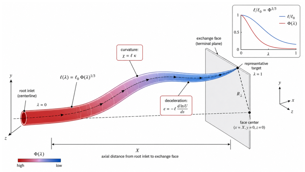
A representative route can be parametrised from the inlet root to a terminal point on the exchanger face in the following form:
Here, is the progress variable from 0 to 1, denoting progress through the manifold. X is the axial length, is the transverse displacement from the centreline to the point, is the transverse-direction unit vector, and is a smooth, monotonic routing parametrisation satisfying
This ensures that a straight connecting segment exists at the inlet and outlet. In the calculations below, we use the quintic smoothstep function to parametrise the routing.
although the formulation is not restricted to this choice. The target displacement can be chosen as any point on the face, but, to compute the maximum displacement, it is chosen as the corner displacement given by
The branching is represented by a second progress function , with and . This, by extension, gives the fraction of flow inside a channel at progress variable . Therefore, if the final number of daughter populations is , the surviving flow fraction carried by one representative population is
For simplicity, and as an initially rational design criterion, we assume a fixed wall shear, which, for tubular flow, gives
where is the root hydraulic diameter. For a circular root channel perfused at flow rate and target wall shear ,
For the representative operating point used here, , , and , this gives .
The differential of root arc length with respect to the progress variable is
The curvature of the planar route is
We define a reduced-curvature severity
and require
The same route must also avoid overly rapid deceleration. At fixed wall shear, the mean velocity scales as . Hence
The dimensionless deceleration severity is therefore
with admissibility condition
The dimensionless deceleration and curvature severities provide a way to combine a complex physiological disturbance with many unknowns into two parameters. In our opinion, simplification through these two parameters increases the utility of the model. Blood compatibility and endothelial function are related not only to flow characteristics such as pulsatility, Reynolds number, flow detachment, and washout but also to the complex endothelial and blood responses to these variables. It is therefore more principled to ask what the physiological ranges of these parameters are in the body and to use these ranges as a best-case sensitivity analysis for axial length.
The parameters for come from curvature data obtained from O’Flynn et al. (2007) for the left and right renal arteries (LRA and RRA), abdominal aorta (AA), and left and right common iliac arteries (LCIA and RCIA). As O’Flynn et al. (2007) did not report corresponding diameter data, Aytac et al. (2003) was used for the LRA and RRA, Kent et al. (2014) for the AA, and Kirkwood et al. (2017) for the LCIA and RCIA. Hence, a plausible curvature-severity range of 0.2-0.7 was used for the sensitivity analysis.

Table 3.
Literature -anchored reduced curvature estimates for selected arteries.
| Artery | Curvature (mm−1) | Diameter (mm) | |
|---|---|---|---|
| Left renal artery (LRA) | 0.114 | 5.68 | 0.648 |
| Right renal artery (RRA) | 0.070 | 5.68 | 0.398 |
| Abdominal aorta (AA) | 0.014 | 20.0 (Kent, 2014) | 0.280 |
| Left common iliac artery (LCIA) | 0.022 | 12.0 | 0.264 |
| Right common iliac artery (RCIA) | 0.029 (O’Flynn et al., 2007) | 12.0 (Kirkwood, 2017) | 0.348 |
For the deceleration severity , defining such a physiologically motivated criterion is not required because, for reasonable axial lengths below 5 cm, the curvature criterion within the physiological range above is dominant.
5.4.1. Discrete Finite-Tree Construction
The single-route model uses a single parametric curve from the root to the terminal face for distribution. To test whether hierarchical routing can reduce the axial requirement, we next constructed an explicit balanced binary tree with
branching generations. The terminal points are distributed on the exchange face as a rectangular grid with
so that . The terminal coordinates were
Starting from the full terminal set, each parent population is split into two equal child populations, alternating the split direction between y and z. The target position of each node is the centroid of its descendant terminal set,
where is the set of terminal outlets supplied by node i. Thus, each branch is assigned a finite transverse offset
The branching planes are assigned using the same hierarchy progress function that was used to denote flow reduction in the analytical model. Specifically, branch generation g is placed at satisfying
This connects the discrete tree to the same smeared hierarchy used in the single-route model. A daughter route accumulates its inherited transverse offsets smoothly after their respective branch points. For a segment belonging to a given root-to-terminal lineage, the transverse centreline can be written as
where is the set of inherited branching offsets for that lineage. The argument of h is clamped to the interval , so each offset is introduced only after its branch plane. The full centreline is then
For each segment, the geometric derivatives are computed directly,
and the curvature is
The same continuum hydraulic scale is retained,
and the same severity metrics are applied:
The minimum axial length X is found by bisection such that
To emphasise, the branching-tree calculation does not provide proof of a global minimum axial length. For instance, instantaneous branching at the root may yield a smaller axial length according to the model. However, such branching would likely generate complex local recirculation/stagnation effects that can be captured only by higher-fidelity modelling.
Figure 9 shows the axial length required for the manifold using the single-step analytical model (A) and the discrete model (B). For both models, a blood-flow rate of 136 mL/min, a wall shear stress of 3 Pa, and an exchanger surface of cm are assumed. For both models, at , curvature has the largest effect on the axial length. Moreover, the parameter dependence is very similar between model A and model B (Figure 9a,b).
5.5. Bioreactor Cell Area Calculations
Proximal tubule area:
The total smooth area (without microvilli amplification) of the proximal tubule in the native kidney is given by:
where is the number of nephrons in a kidney, is the radius of the proximal tubule, and is the length of the proximal tubule.
The mean number of nephrons, , is 860,000 (Denic et al., 2017). The mean diameter of the proximal tubule is (Denic et al., 2023). The length of the proximal tubule is a function of age, with the adult proximal-tubule length being approximately 18.7 mm (Darmady et al., 1972). Using these values, the native proximal-tubule area per kidney is . If a native proximal-tubule water-recovery rate of 65% and a GFR of 60 mL/min are assumed, the recovery is .
The artificial kidney, in its chosen minimal operating regime, must reabsorb 12.3 mL/min. This means that the required proximal-tubule area, assuming native function, is approximately .
Thick ascending limb area:
With an ultrafiltration rate of 16.4 mL/min (23.62 L/day), the daily filtered sodium load, assuming a constant plasma concentration, is 3306 mmol/day. If the PTC recovers 74.7% iso-osmotically, then the remaining load is 837 mmol/day. As noted above, this is a very onerous load. Assuming a daily urinary excretion of 154 mmol/day, equivalent to 9 g/day of table salt, which is the average table-salt intake in the West, the required reabsorption in the TAL is 682 mmol/day; therefore, the reabsorption rate is 0.476 mmol/min.
The requisite TAL area can be approximated from animal studies (Cabral et al., 2022). Here, the chloride flux, computed as the average of the controls, is 285 pmol/min/mm. This chloride flux is taken as a proxy for sodium transport, indicating a similar rate for sodium. Dividing the required transport rate by this flux gives a required TAL length of mm. The inner TAL diameter in the rabbit in which Cabral et al. (2022) measured chloride transport is (Rocha & Kokko, 1973). This means that the total required area is .
Rocha & Kokko measured sodium reabsorption directly. They found 0.240 nmol/mm/min for sodium reabsorption. This means that mm of TAL is required. Using the diameters they reported, the total required area is . This number is consistent with that obtained using the chloride proxy but, as it is a more direct measure, is used as the estimate. This is a mammalian baseline; no human-specific values have yet been identified in the literature.
Distal area:
The iso-osmotic potassium handling in the proximal tubule alone is inadequate. In the 6 L/day of fluid not reabsorbed by the proximal tubule, 30 mmol/day of potassium is excreted. If a dietary consumption of 80 mmol/day is assumed, then 50 mmol/day (0.0347 mmol/min) must be excreted.
The cells in the connecting and collecting tubules have the role of potassium secretion. The potassium secretion found in isolated and perfused collecting tubules of New Zealand White rabbits (Woda et al., 2001) was 23.4 pmol/min/mm. This was strongly flow-dependent, as shear stresses below 0.1 dyne/cm2 produced secretion rates of pmol/min/mm.
At 23.4 pmol/min/mm, the required distal length is mm. The diameter of the collecting tubule in the rabbit is (Jacobson et al., 1976); the necessary distal area is therefore .
Total Area:
The total cell-laden area, assuming kidney-like capacity, is .
5.6. Hemofiltration Concentration Polarisation Model
5.6.1. Model Scope and Assumptions
We model ultrafiltration (UF) in a single straight blood channel of length L and uniform gap height h formed by parallel plates (slit). The channel has width W and is bordered by 2 permeable walls (membranes). The axial coordinate is x. The axial whole-blood flow rate is and decreases with x due to solvent removal through the permeable wall(s). Red blood cells (RBCs) and albumin are assumed membrane-rejected (no RBC or albumin permeation). A concentration-polarisation (CP) model relates wall and bulk albumin concentrations and is used to compute oncotic opposition to UF.
For the model, we assume steady, laminar, fully developed slit flow; constant effective viscosity ; uniform h and W; no lateral maldistribution; albumin CP represented by film theory with mass-transfer coefficient ; and oncotic pressure represented by an empirical polynomial in serum protein concentration at the wall. We do not account for the formation of a cell layer on the membrane, which may reduce permeability further. Blood viscosity is also taken to be constant and does not change with increased hematocrit.
At each axial position x, the model is evaluated in the following solution sequence:
5.6.2. Step 1: Hydrodynamic Kinematics and Shear
Given the local flow rate , the mean axial velocity is
where W is the channel width and h is the channel gap height. For fully developed laminar flow between parallel plates, the wall shear rate and shear stress are
where is the effective dynamic viscosity.
5.6.3. Step 2: RBC Conservation and Hematocrit
At the inlet, the discharge hematocrit is set at , and the RBC volumetric flow rate is defined as
RBCs are assumed to be perfectly retained by the membrane; therefore, is constant along the channel. The discharge hematocrit is then
This relation captures hemoconcentration induced by ultrafiltration.
5.6.4. Step 3: Plasma Flow and Bulk Albumin Concentration
The plasma flow rate is
Relevant plasma proteins are assumed to be completely rejected by the membrane, so their plasma mass flow is conserved. With inlet serum protein concentration , the bulk concentration along the channel is
Thus, increases as plasma is removed.
5.6.5. Step 4: Mass-transfer Coefficient and Concentration Polarisation
Concentration polarisation is represented via the film-theory relation
where is the wall albumin concentration, is the UF flux through one membrane wall, and is the local mass-transfer coefficient.
To account for entrance-region mass transfer, is computed from a Graetz-number correlation. A local Graetz number is defined as
where is the albumin diffusivity. The mass-transfer coefficient is then
This formulation produces a larger near the entrance (larger ), modulating CP and therefore the wall concentration .
5.6.6. Step 5: Axial Pressure Drop (Blood-Side Driving Pressure)
The blood-side driving pressure for UF is represented by a pressure proxy that decreases along x due to viscous losses in the slit:
with inlet condition
where is a prescribed inlet driving pressure.
5.6.7. Step 6: Local UF Flux from a Starling-type Law with Oncotic Opposition
The local UF flux through one permeable wall is governed by
where is the hydraulic permeability in SI units and is the oncotic pressure evaluated at the wall concentration.
The pure buffer permeability is specified as in LMH/bar and converted to SI using the factor F (LMH→m/s):
where m/s per LMH. The oncotic pressure is represented by an empirical polynomial in terms of in g/dL:
where is expressed in mmHg when is expressed in the same concentration units as .
Because depends on J through CP, the flux law is implicit. Substituting gives the nonlinear equation for :
with and interpreted in consistent pressure units.
5.6.8. Step 7: Flow Reduction Due to UF (Axial Mass Conservation)
UF removes solvent across permeable walls, reducing the axial whole-blood flow rate according to
where is the number of permeable walls and W is the channel width. This updates and closes the feedback loop: Q determines U, , , , and , which together determine J, which in turn determines the evolution of Q.
5.7. Hemofiltration Experiment
The one-dimensional ultrafiltration model was validated using a flow cell under blood flow. The system comprised a flow cell, a membrane, a peristaltic pump, and a syringe pump. We used whole blood and TBS buffer to test permeability during blood filtration and at baseline, respectively. The flow rate was set to 1.2 mL/min such that filtration was performed in crossflow. The membrane was a commercially available, circular, 13-mm-diameter anodic aluminium oxide membrane with a thickness of . The diameter exposed to the flow, and thus available for filtration, was 10 mm. The membrane has a pore size of nm, which is far above the cut-off for albumin. However, once the membrane is fouled by blood, rejection increases substantially, such that complete rejection can be assumed. The blood-gap height h was set to . Assuming parallel-plate flow, the shear was set to 1 Pa.
The loop was first run with TBS buffer to determine the baseline pure-buffer permeability, which was 800 LMH/bar. Anticoagulated (sodium citrate) whole blood was then introduced into the system. The test was run so as to saturate the membrane with foulant, allowing reversible fouling due to concentration polarisation to be distinguished from irreversible fouling. After whole-blood exposure, PBS permeability was measured again to recompute the pure-buffer permeability of the irreversibly fouled membrane, which was 360 LMH/bar. After this, anticoagulated whole blood was run again at different pressures, and the filtration rate was measured.
Figure 10.
Hemofiltration experiment.
5.8. Cellularisation
The epithelial cells in suspension are (Homan et al. 2016). The pre-seeding channel must therefore be . Experiments have shown that such channels can indeed be seeded with epithelial cells (Venzac et al., 2018). Scaling such seeding will, however, remain a considerable challenge.
A simple first-event model of direct cell seeding was developed to assess scaling feasibility. The model ignores cell migration, cell deformation, flow bypass, clog growth, and any 2D effects that result from using slit-like channel geometries. The failure criterion is taken simply as clogging when the critical channel dimension falls below one cell length.
In the model, after the first local patch of cells attaches to both walls, the critical channel-gap distance drops to
where is the first-contact height of newly attached epithelial cells. The cumulative failure hazard for a first loading step followed by later cell reperfusions is then
Here, is the number of cells passing during the kth cell perfusion, and is the fraction of those objects whose size exceeds the relevant critical gap. The probability that a local clog appears is then given by the Poisson distribution:
In this model, the principal driver of clogging is the term. This term is determined by the heterogeneity of the cell suspension. Large aggregates, doublets, or triplets can easily exceed critical gap dimensions.
Figure 11 shows two successive seedings of the same channel for three aggregate models: low, baseline, and high, at 0.1%, 1%, and 10%, respectively. The number of cells is determined by the volume of the tube to be seeded and the seeding concentration. As a favourable assumption, only doublets, with a size of , are considered.
Under the model assumptions, seeding channels below is not feasible (left). This also means that cellularised channel dimensions cannot be lower than . Additionally, secondary seeding stages push the pre-seeding channel diameter to still higher values. This means that uniform cell distribution across the entire channel before attachment is required for successful cellularisation of small channels.
Author Contributions
T. Irmak: Conceptualization, Data curation, Formal analysis, Investigation, Methodology, Writing – original draft, Writing – review & editing. J.C. Vollenbroek: Validation, Writing – review & editing. R. van Gaal: Validation, Writing – review & editing. B. Bera: Validation, Writing – review & editing. F. P. Wieringa: Writing – review & editing. K.G.F. Gerritsen: Funding acquisition, Validation, Writing – review & editing.
Acknowledgments
This work was funded by KIDNEW (HORIZON-EIC-2022 Pathfinder GA 101099092). We are very grateful to Monika Irmak Šalandová for her work on the schematic figure.
Conflicts of Interest
The authors declare that they have no conflicts of interest.
References
- West, G.B., J.H. Brown, and B.J. Enquist. 1997. A general model for the origin of allometric scaling laws in biology. Science 276: 122–126. [Google Scholar] [CrossRef] [PubMed]
- West, G.B., J.H. Brown, and B.J. Enquist. 1999. The fourth dimension of life: Fractal geometry and allometric scaling of organisms. Science 284: 1677–1679. [Google Scholar] [CrossRef] [PubMed]
- Himmelfarb, J., R. Vanholder, R. Mehrotra, and M. Tonelli. 2020. The current and future landscape of dialysis. Nature Reviews Nephrology 16: 573–585. [Google Scholar] [CrossRef] [PubMed]
- Ramada, D.L., J. de Vries, J. Vollenbroek, N. Noor, O. ter Beek, S.M. Mihăilă, F.P. Wieringa, R. Masereeuw, K.G.F. Gerritsen, and D.F. Stamatialis. 2023. Portable, wearable and implantable artificial kidney systems: Needs, opportunities and challenges. Nature Reviews Nephrology 19: 481–490. [Google Scholar] [CrossRef] [PubMed]
- Wieringa, F.P., S. Suran, H. Søndergaard, S. Ash, C. Cummins, A.R. Chaudhuri, T. Irmak, K. Gerritsen, and J. Vollenbroek. 2025. The future of technology-based kidney replacement therapies: An update on portable, wearable, and implantable artificial kidneys. American Journal of Kidney Diseases 85: 787–796. [Google Scholar] [CrossRef] [PubMed]
- United States Renal Data System. 2024. USRDS Annual Data Report: Epidemiology of Kidney Disease in the United States. Technical report. National Institute of Diabetes and Digestive and Kidney Diseases, National Institutes of Health. [Google Scholar]
- Hoekstra, M.W.F., R. Boenink, M. Bonthuis, B.A. Boerstra, M.E. Astley, I.R. Montez de Sousa, N. Gjorgjievski, H. Resic, N. Mitsides, K. Hommel, and et al. 2026. The ERA Registry Annual Report 2023: Epidemiology of kidney replacement therapy in Europe, with a focus on age comparisons. Clinical Kidney Journal 19: sfag036. [Google Scholar] [CrossRef] [PubMed]
- UK Renal Registry. 2021. UK Renal Registry 23rd Annual Report: Data to 31/12/2019. Technical report. The Renal Association. [Google Scholar]
- Wieringa, F.P., M.I. Sheldon, and A. Hidalgo-Simon. 2020. Regulatory approaches to stimulate innovative renal replacement therapies. Nature Reviews Nephrology 16: 546–547. [Google Scholar] [CrossRef] [PubMed]
- Song, J.J., J.P. Guyette, S.E. Gilpin, G. Gonzalez, J.P. Vacanti, and H.C. Ott. 2013. Regeneration and experimental orthotopic transplantation of a bioengineered kidney. Nature Medicine 19: 646–651. [Google Scholar] [CrossRef] [PubMed]
- Huang, B., P. Medina, J. He, Z. Zeng, S. Kim, J. Romo, K. Koppitch, C.C. Zhang, G. Gyarmati, Y. Park, and et al. 2025. Spatially patterned kidney assembloids recapitulate progenitor self-assembly and enable high-fidelity in vivo disease modeling. Cell Stem Cell 32: 1614–1633.e13. [Google Scholar] [CrossRef] [PubMed]
- Yokote, S., H. Matsunari, S. Iwai, S. Yamanaka, A. Uchikura, E. Fujimoto, K. Matsumoto, H. Nagashima, E. Kobayashi, and T. Yokoo. 2015. Urine excretion strategy for stem cell-generated embryonic kidneys. Proceedings of the National Academy of Sciences 112: 12980–12985. [Google Scholar] [CrossRef] [PubMed]
- Fissell, W.H., A. Dubnisheva, A.N. Eldridge, A.J. Fleischman, A.L. Zydney, and S. Roy. 2009. High-performance silicon nanopore hemofiltration membranes. Journal of Membrane Science 326: 58–63. [Google Scholar] [CrossRef] [PubMed]
- Kim, E.J., C. Chen, R. Gologorsky, A. Santandreu, A. Torres, N. Wright, M.S. Goodin, J. Moyer, B.W. Chui, C. Blaha, and et al. 2023. Feasibility of an implantable bioreactor for renal cell therapy using silicon nanopore membranes. Nature Communications 14: 4890. [Google Scholar] [CrossRef] [PubMed]
- van den Berg, C.W., S.J. Dumas, M.H. Little, and T.J. Rabelink. 2025. Challenges in maturation and integration of kidney organoids for stem cell-based renal replacement therapy. Kidney International 107: 262–270. [Google Scholar] [CrossRef] [PubMed]
- Moyer, J., M.W. Wilson, T.A. Sorrentino, A. Santandreu, C. Chen, D. Hu, A. Kerdok, E. Porock, N. Wright, J. Ly, and et al. 2023. Renal embolization-induced uremic swine model for assessment of next-generation implantable hemodialyzers. Toxins 15: 547. [Google Scholar] [CrossRef] [PubMed]
- Roux, E., P. Bougaran, P. Dufourcq, and T. Couffinhal. 2020. Fluid shear stress sensing by the endothelial layer. Frontiers in Physiology 11: 861. [Google Scholar] [CrossRef] [PubMed]
- Zhou, H.L., X.Z. Jiang, and Y. Ventikos. 2023. Role of blood flow in endothelial functionality: A review. Frontiers in Cell and Developmental Biology 11: 1259280. [Google Scholar] [CrossRef] [PubMed]
- Neal, C.R., K.P. Arkill, J.S. Bell, K.B. Betteridge, D.O. Bates, C.P. Winlove, A.H.J. Salmon, and S.J. Harper. 2018. Novel hemodynamic structures in the human glomerulus. American Journal of Physiology-Renal Physiology 315: F1370–F1384. [Google Scholar] [CrossRef] [PubMed]
- Feaugas, T., G. Newman, S.T. Calzuola, A. Domingues, W. Arditi, C. Porrini, E. Roy, and C.M. Perrault. 2023. Design of artificial vascular devices: Hemodynamic evaluation of shear-induced thrombogenicity. Frontiers in Mechanical Engineering 9: 1060580. [Google Scholar] [CrossRef]
- Eloot, S., F. Vanommeslaeghe, I. Josipovic, M. Boone, and W. Van Biesen. 2023. Association between anticoagulation strategy and quality of life in chronic hemodialysis patients. Scientific Reports 13: 15105. [Google Scholar] [CrossRef] [PubMed]
- Halbert, R.J., G. Nicholson, R.J. Nordyke, A.J. Pilgrim, and M. Nikam. 2020. Patency of ePTFE arteriovenous graft placements in hemodialysis patients: Systematic literature review and meta-analysis. Kidney360 1: 1437–1446. [Google Scholar] [CrossRef] [PubMed]
- Painter, P.R., P. Edén, and H.U. Bengtsson. 2006. Pulsatile blood flow, shear force, energy dissipation and Murray’s law. Theoretical Biology and Medical Modelling 3: 31. [Google Scholar] [CrossRef] [PubMed]
- Wieringa, F.P., D. Bolhuis, H. Søndergaard, S.R. Ash, C. Cummins, K.G.F. Gerritsen, J. Vollenbroek, and T. Irmak. 2024. Transportable, portable, wearable and (partially) implantable haemodialysis systems: Comparison of technologies and readiness levels. Clinical Kidney Journal 17: sfae259. [Google Scholar] [CrossRef] [PubMed]
- National Kidney Foundation. 2015. KDOQI clinical practice guideline for hemodialysis adequacy: 2015 update. American Journal of Kidney Diseases 66: 884–930. [Google Scholar] [CrossRef] [PubMed]
- Zhuo, J.L., and X.C. Li. 2013. Proximal nephron. Comprehensive Physiology 3: 1079–1123. [Google Scholar] [CrossRef] [PubMed]
- Bankir, L., and B. Yang. 2012. New insights into renal urea and glucose handling by the kidney, and the urine concentrating mechanism. Kidney International 81: 1179–1198. [Google Scholar] [CrossRef] [PubMed]
- Layton, A.T., K. Laghmani, V. Vallon, and A. Edwards. 2016. Solute transport and oxygen consumption along the nephrons: Effects of Na+ transport inhibitors. American Journal of Physiology-Renal Physiology 311: F1217–F1229. [Google Scholar] [CrossRef] [PubMed]
- Blaine, J., M. Chonchol, and M. Levi. 2015. Renal control of calcium, phosphate, and magnesium homeostasis. Clinical Journal of the American Society of Nephrology 10: 1257–1272. [Google Scholar] [CrossRef] [PubMed]
- Wouda, R.D., L. Vogt, and E.J. Hoorn. 2021. Personalizing potassium management in patients on haemodialysis. Nephrology Dialysis Transplantation 36: 13–18. [Google Scholar] [CrossRef] [PubMed]
- Clerin, V., H. Saito, K.J. Filipski, A.H. Nguyen, J. Garren, J. Kisucka, M. Reyes, and H. Jüppner. 2020. Selective pharmacological inhibition of the sodium-dependent phosphate cotransporter NPT2a promotes phosphate excretion. Journal of Clinical Investigation 130: 6510–6522. [Google Scholar] [CrossRef] [PubMed]
- Wang, T., S. Weinbaum, and A.M. Weinstein. 2017. Regulation of glomerulotubular balance: Flow-activated proximal tubule function. Pflügers Archiv - European Journal of Physiology 469: 643–654. [Google Scholar] [CrossRef] [PubMed]
- Homan, K.A., D.B. Kolesky, M.A. Skylar-Scott, J. Herrmann, H. Obuobi, A. Moisan, and J.A. Lewis. 2016. Bioprinting of 3D convoluted renal proximal tubules on perfusable chips. Scientific Reports 6: 34845. [Google Scholar] [CrossRef] [PubMed]
- Deen, W.M., C.R. Robertson, and B.M. Brenner. 1974. Concentration polarization in an ultrafiltering capillary. Biophysical Journal 14: 412–431. [Google Scholar] [CrossRef] [PubMed]
- van den Berg, G.B., I.G. Rácz, and C.A. Smolders. 1989. Mass transfer coefficients in cross-flow ultrafiltration. Journal of Membrane Science 47: 25–51. [Google Scholar] [CrossRef]
- Slaughter, M.S., J.G. Rogers, C.A. Milano, S.D. Russell, J.V. Conte, D. Feldman, B. Sun, A.J. Tatooles, R.M. Delgado, J.W. Long, and et al. 2009. Advanced heart failure treated with continuous-flow left ventricular assist device. New England Journal of Medicine 361: 2241–2251. [Google Scholar] [CrossRef] [PubMed]
- Wilmes, A., L. Aschauer, A. Limonciel, W. Pfaller, and P. Jennings. 2014. Evidence for a role of claudin 2 as a proximal tubular stress responsive paracellular water channel. Toxicology and Applied Pharmacology 279: 163–172. [Google Scholar] [CrossRef] [PubMed]
- Hunter, K., S. Roy, A. Ice, R.C. Evans, R. Zent, and W.H. Fissell. 2025. Inhibition of TGF-β in tubule cells increases respiration via upregulation of respiratory genes. Tissue Engineering Part A. [Google Scholar] [CrossRef] [PubMed]
- Táborská, J., Z. Riedelová, E. Brynda, P. Májek, and T. Riedel. 2021. Endothelialization of an ePTFE vessel prosthesis modified with an antithrombogenic fibrin/heparin coating enriched with bound growth factors. RSC Advances 11: 5903–5913. [Google Scholar] [CrossRef] [PubMed]
- Remuzzi, A., M. Figliuzzi, B. Bonandrini, S. Silvani, N. Azzollini, R. Nossa, A. Benigni, and G. Remuzzi. 2017. Experimental evaluation of kidney regeneration by organ scaffold recellularization. Scientific Reports 7: 43502. [Google Scholar] [CrossRef] [PubMed]
- Ono, A., R. Ouchi, Y. Kumagai, M. Suda, T. Yamashita, Y. Taguchi, and R. Sudo. 2025. Flow-driven construction of capillary-scale vessels with predefined geometries in natural hydrogels. Materials Today Bio 35: 102433. [Google Scholar] [CrossRef] [PubMed]
- Linville, R.M., N.F. Boland, G. Covarrubias, G.M. Price, and J. Tien. 2016. Physical and chemical signals that promote vascularization of capillary-scale channels. Cellular and Molecular Bioengineering 9: 73–84. [Google Scholar] [CrossRef] [PubMed]
- Wolf, K.J., R.C. van Gaal, S.G.M. Uzel, J.E. Rubins, A.N. Klaus, A. Printz, P. Nair, K.T. Kroll, P. Stankey, L.M. Satlin, and et al. 2026. Perfusable 3D models of ureteric bud and collecting duct tubules. Cell Biomaterials 2: 100297. [Google Scholar] [CrossRef]
- Oliveira, M., P.P. Sarker, I. Skovorodkin, A. Kalantarifard, T. Haskavuk, J. Mac Intyre, E. Nallukunnel Raju, S. Nooranian, H. Shioda, M. Nishikawa, and et al. 2024. From from ex ovo to in vitro: Xenotransplantation and vascularization of mouse embryonic kidneys in a microfluidic chip. Lab on a Chip 24: 4816–4826. [Google Scholar] [CrossRef] [PubMed]
Figure 1.
Orientating schematic diagram of the artificial kidney. The artificial kidney is composed of 4 major segments; blood distribution, hemofilter, efferent arteriole and bioreactor for reabsorption . The hemofilter, efferent arteriole and bioreactor are arranged in a dense exchange-bed which the manifold perfuses. Each component has a certain axial length given as; , , , these add up to the total implantation span,
Figure 1.
Orientating schematic diagram of the artificial kidney. The artificial kidney is composed of 4 major segments; blood distribution, hemofilter, efferent arteriole and bioreactor for reabsorption . The hemofilter, efferent arteriole and bioreactor are arranged in a dense exchange-bed which the manifold perfuses. Each component has a certain axial length given as; , , , these add up to the total implantation span,
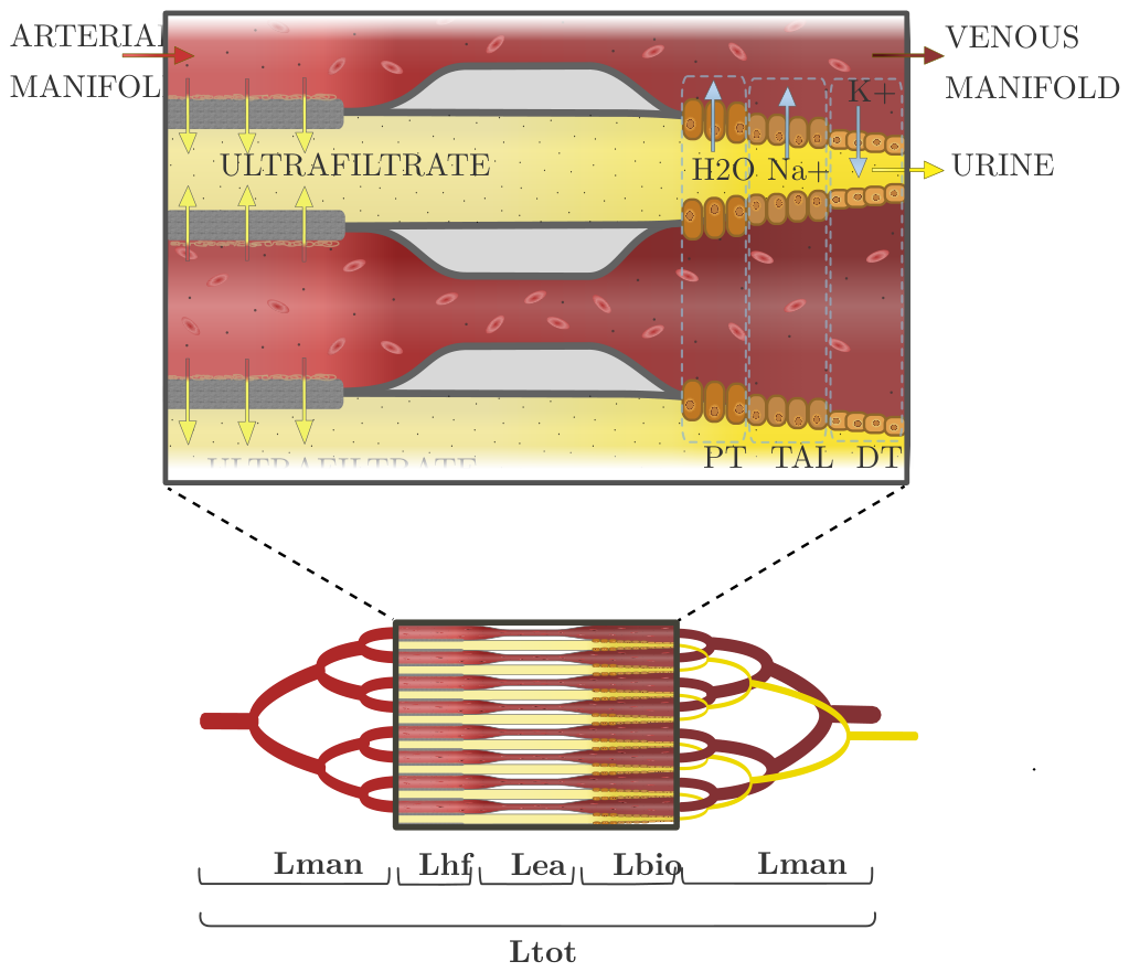
Figure 2.
Schematic diagram illustrating the two-level modelling frameworks used to estimate the lower bound on the axial length of a slit-stack exchanger. A, continuum model in which the branching hierarchy is represented as a smeared stream-tube specified with a curve routed from a root inlet to a terminal exchange face. The local characteristic length scale is given by , the maximum curvature is constrained by the non-dimensional curvature and deceleration . This model provides a single-stage analytical estimate of the minimum axial span X required to route flow to a representative target offset by . B, discrete branch-by-branch routing model in which the global root-to-face path is replaced by locally specified curve stages between branch points. This permits higher allowable curvature in distal branches as the local length and flow scale decrease.
Figure 2.
Schematic diagram illustrating the two-level modelling frameworks used to estimate the lower bound on the axial length of a slit-stack exchanger. A, continuum model in which the branching hierarchy is represented as a smeared stream-tube specified with a curve routed from a root inlet to a terminal exchange face. The local characteristic length scale is given by , the maximum curvature is constrained by the non-dimensional curvature and deceleration . This model provides a single-stage analytical estimate of the minimum axial span X required to route flow to a representative target offset by . B, discrete branch-by-branch routing model in which the global root-to-face path is replaced by locally specified curve stages between branch points. This permits higher allowable curvature in distal branches as the local length and flow scale decrease.
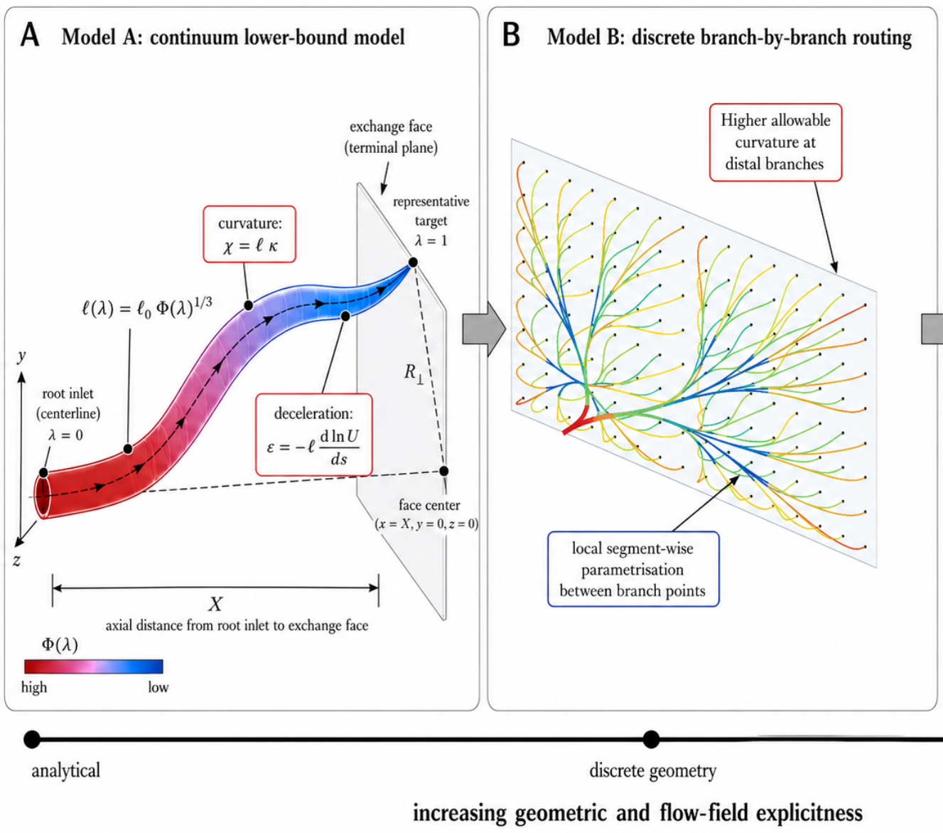
Figure 3.
(a) Axial length as a function of the allowable curvature-severity criterion for a fixed for both model A (dashed line) and model B (solid line). (b) Axial length versus the number of branches for discrete model B, where is the final number of terminal units.
Figure 3.
(a) Axial length as a function of the allowable curvature-severity criterion for a fixed for both model A (dashed line) and model B (solid line). (b) Axial length versus the number of branches for discrete model B, where is the final number of terminal units.
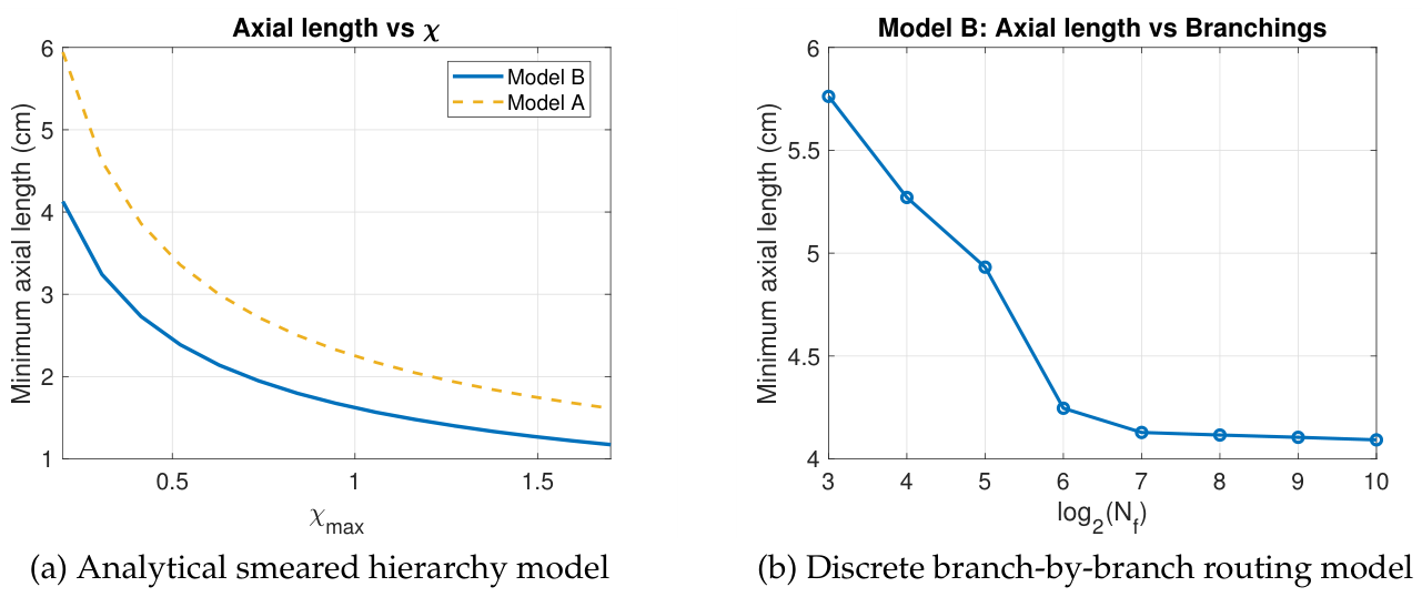
Figure 5.
Hemofiltration-model validation and full-scale extrapolation. (a) Experimental and predicted ultrafiltration flow rate as a function of transmembrane pressure. (b) Minimum active membrane area as a function of blood-channel height and membrane permeability. (c) Required filtration length as a function of the number of layers at the reference blood-channel height. (d) Required area for hemofiltration as a function of the number of layers at the reference membrane permeability.
Figure 5.
Hemofiltration-model validation and full-scale extrapolation. (a) Experimental and predicted ultrafiltration flow rate as a function of transmembrane pressure. (b) Minimum active membrane area as a function of blood-channel height and membrane permeability. (c) Required filtration length as a function of the number of layers at the reference blood-channel height. (d) Required area for hemofiltration as a function of the number of layers at the reference membrane permeability.
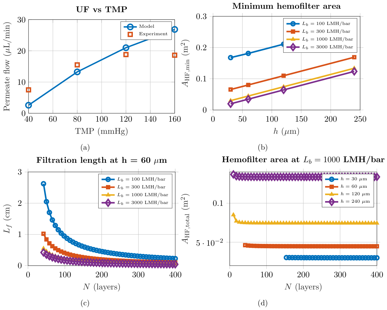
Figure 6.
Geometric-feasibility region for the 2D bioreactor, given constraints on axial length, minimum filtrate-channel height, and packing. (a) No feasible region exists if the separation between the blood and filtrate sides is , where is the epithelial-layer thickness. (b) Feasible region with a separation distance of . Solid contours indicate blood-channel height, dotted contours indicate the number of layers, and dashed contours indicate blood shear stress.
Figure 6.
Geometric-feasibility region for the 2D bioreactor, given constraints on axial length, minimum filtrate-channel height, and packing. (a) No feasible region exists if the separation between the blood and filtrate sides is , where is the epithelial-layer thickness. (b) Feasible region with a separation distance of . Solid contours indicate blood-channel height, dotted contours indicate the number of layers, and dashed contours indicate blood shear stress.
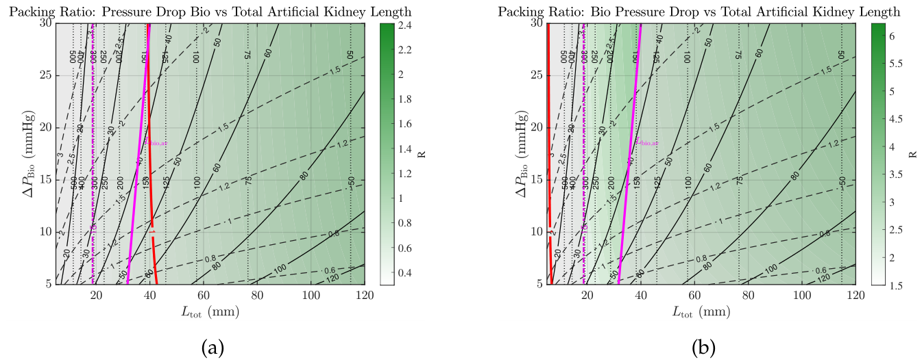
Figure 7.
(a) Geometric feasibility as a function of total separation distance and device thickness for the artificial kidney in a 2D slit-stack design. (b)Percentage of the design space remaining as the proximal tubule area increases as a function of PTEC under-performance when compared with in the native kidneys.
Figure 7.
(a) Geometric feasibility as a function of total separation distance and device thickness for the artificial kidney in a 2D slit-stack design. (b)Percentage of the design space remaining as the proximal tubule area increases as a function of PTEC under-performance when compared with in the native kidneys.
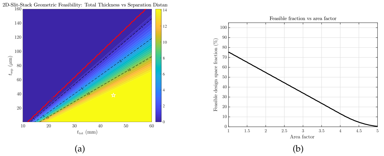
Figure 9.
Surface plots of the necessary axial length with respect to the deceleration and curvature criteria for the analytical model (a) and the discrete model (b).
Figure 9.
Surface plots of the necessary axial length with respect to the deceleration and curvature criteria for the analytical model (a) and the discrete model (b).
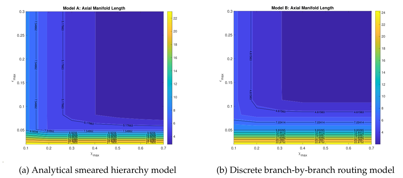
Figure 11.
Predictions of the seeding-failure model for different aggregate distributions and for initial seeding (left) and second seeding (right).
Figure 11.
Predictions of the seeding-failure model for different aggregate distributions and for initial seeding (left) and second seeding (right).
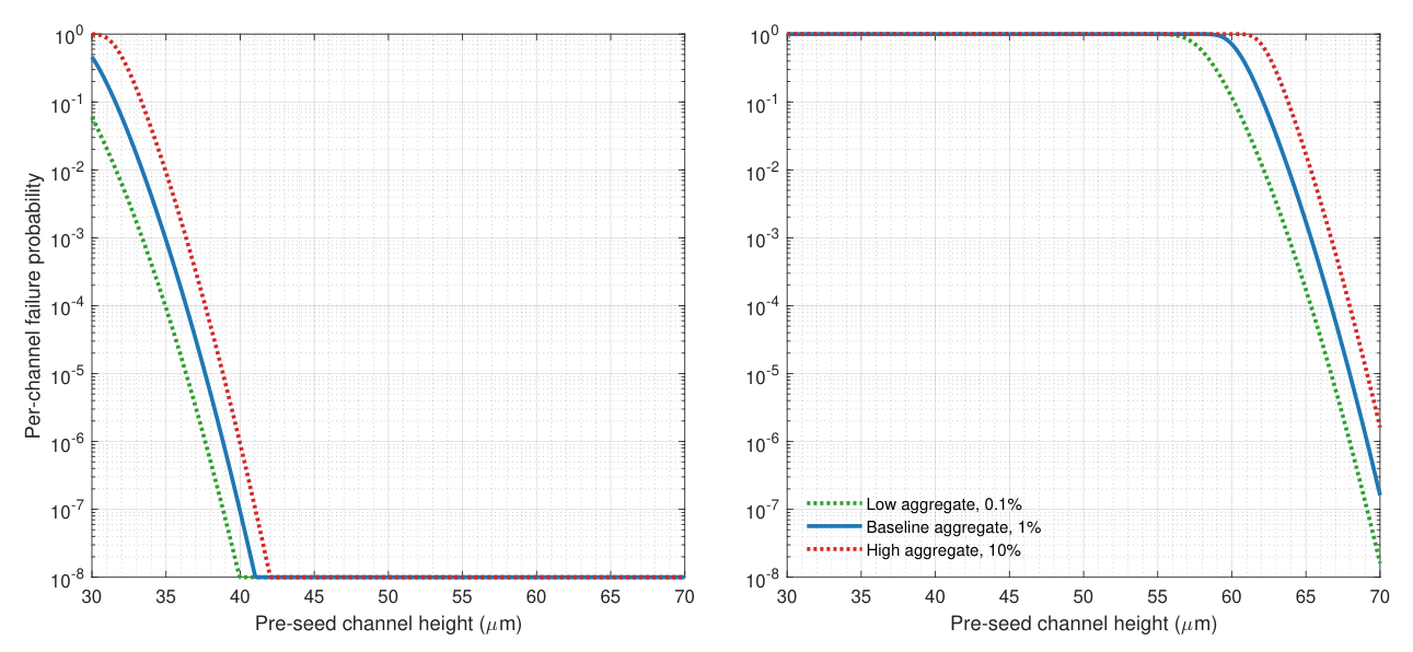
Table 1.
Daily loss of solute for of urine.
| Solute | 6 L (mmol/day) |
|---|---|
| Sodium (Na) | 840 |
| Potassium (K) | 30 |
| Phosphorus | < 5.3 |
Table 2.
Cell-laden area needed for each module.
| Module | Area |
|---|---|
| PT | 0.895 |
| TAL | 0.16 |
| DT | 0.093 |
| Total Area | 1.15 |
Disclaimer/Publisher’s Note: The statements, opinions and data contained in all publications are solely those of the individual author(s) and contributor(s) and not of MDPI and/or the editor(s). MDPI and/or the editor(s) disclaim responsibility for any injury to people or property resulting from any ideas, methods, instructions or products referred to in the content. |
© 2026 by the authors. Licensee MDPI, Basel, Switzerland. This article is an open access article distributed under the terms and conditions of the Creative Commons Attribution (CC BY) license (http://creativecommons.org/licenses/by/4.0/).
Copyright: This open access article is published under a Creative Commons CC BY 4.0 license, which permit the free download, distribution, and reuse, provided that the author and preprint are cited in any reuse.