
Submitted:
29 August 2026
Posted:
31 August 2026
You are already at the latest version
Abstract
Cold Spray (CS) technology has established itself as a versatile solid-state deposition process with significant potential for both repair applications and manufacturing of bulk parts. This review examines recent advances in CS, emphasizing its unique ability to deposit metals and composites without melting, thereby minimizing oxidation, thermal distortion, and residual stresses. These advantages have positioned CS as a technique with all the credentials for being used within industry for restoring damaged components, especially, where high microstructural quality and mechanical integrity are critical. This review paper synthesizes current knowledge on different coatings/deposits produced by CS, the processing of present-day and future metals/alloys by cold spray, and specific requirements for industrial applications employing this technology. Additionally, it highlights the growing use of CS as an additive manufacturing (AM) technology, where layer-by-layer deposition enables the fabrication of complex geometries, gradient materials, and hybrid structures. Advances in cold spray additive manufacturing (CSAM) technology and deposition strategies are also discussed. Remaining challenges, including in-situ monitoring, predictive modeling, and the need for standardized qualification protocols, are identified. Overall, this review underscores CS transformative role in enabling high-performance repairs and novel AM strategies, while outlining future research directions to expand its industrial adoption.
Keywords:
cold spray technology
; repairing
; additive manufacturing
; coatings
1. Introduction
The deposition of metallic, ceramic or composite materials in the form of particles over a surface to modify its original properties can be achieved by employing different processes in which the energy provided to those particles has a thermal and/or a kinetic origin. The well-known plasma or combustion-based thermal spray processes privilege thermal input to the particles over kinetic acceleration, whereas in other processes like cold spray most of the energy involved is kinetical in nature. As the amount of thermal energy in such a process is quite limited, cold spray, also known as cold gas dynamic spray, supersonic particle deposition, or kinetic spray, is mainly a solid-state powder-consolidation technology. Its operation principle is based on heating and expanding a pressurized gas-usually nitrogen or helium-through a converging-diverging de Laval nozzle to accelerate powder particles to 300-1200 m/s. [1] Although the gas is heated, particle residence time is short, and the feedstock remains below its melting temperature. Thus, “cold” refers to deposition without melting, not to room-temperature operation.
Deposition is governed by impact conditions. Particles must exceed a material-dependent critical velocity; below such velocity they rebound or erode the surface, while excessive velocity produces erosion again. Hence, a deposition window highly dependent on particle velocity exists for different substrate-coating combinations. Critical velocity varies with material strength, particle temperature, particle size distribution, particle morphology, oxide state, substrate condition, and impact angle. Bonding is promoted by severe localized plastic deformation of particles and substrate at extremely high strain rates, where interfacial jetting, rupture/expulsion of oxide films, mechanical interlocking, metal-to-metal contact, and short-range metallurgical bonding play an important role. Adiabatic shear localization was long considered essential for bonding [2], but later work showed that jetting and adhesion can occur without it [3]; therefore, bonding can be viewed as a coupled deformation and interface-cleaning process.
The key difference of cold spray from other thermal spray processes, such as plasma spray or HVOF, and from fusion-based additive manufacturing technologies, is the absence of melting and solidification. Cold spray therefore minimizes oxidation, evaporation, decomposition, grain growth, dilution, and formation of a heat-affected zone. Hence, feedstock microstructures, including nanocrystalline, metastable or oxygen-sensitive states, can be preserved more effectively either in a coating for protection/restoration or a 3D printed part. When this technology is employed to produce coatings, heat input and distortion of the component are comparatively low, and repeated particle impacts may introduce beneficial compressive peening effects. On the other hand, when used as an additive manufacturing process, thick deposits can be produced at high rates under atmospheric conditions. Such deposits can be formed by dissimilar metals, graded materials, and metal–matrix-composites providing the powders have adequate deformability and compatibility [4]. Robotic arms or multi-axis-controlled systems are quite popular for producing 3D parts by cold spray, as they are required to accurately manipulate the system to produce high-quality parts. Furthermore, the cold spray process has successfully evolved from large and complex high-pressure systems to portable user-friendly low-pressure guns, which are commonly employed for field repairs employing mainly ductile metals [5].
Cold spray is therefore attractive for processing aluminum, copper, titanium, nickel and selected alloys, particularly when low oxidation, high conductivity or minimal thermal disturbance is required. Applications include corrosion protection, conductive layers, wear-resistant composites, and restoration of expensive components. Compared with fusion repair, the process avoids solidification shrinkage, hot cracking, and large tensile thermal stresses. It can also place material only where needed, reducing replacement cost and waste. However, deposition relies on plastic deformation, so ductile metals are easier to spray than hard brittle alloys or monolithic ceramics. Hard phases are normally embedded in a ductile metallic matrix rather than deposited alone [1].
Although cold spray is considered as a technology for producing high-quality coatings, there are several aspects that must be taken into consideration when this process is selected as a tool for producing new components or repairing damaged infrastructure. Cold spray deposits may contain porosity, microcracks or incompletely bonded particle boundaries, especially when processing high-strength alloys. For some materials, severe deformation produces important work hardening; therefore, the as-sprayed material may show high hardness and low ductility, resulting in lower cohesive strength. Depending on the feedstock employed, post-treatments such as annealing, solution treatment, aging, hot isostatic pressing, rolling, friction-stir processing, or localized laser melting may be needed to close pores and strengthen interfaces. These steps add cost and may affect the substrate adversely. Other limitations include use of expensive gases for high-pressure systems, constant replacement of components such as nozzles due to excessive erosion or clogging, and drawbacks associated with any other thermal spray process such as particle rebound, overspray, limited line-of-sight access, noise and dust-control requirements, and sensitivity to standoff distance and spray angle [6].
For repair of metallic components, the most established role for low- and high-pressure cold spray systems is dimensional restoration of localized wear, fretting, corrosion, or machining damage [7]. Before the actual repair is performed, optimization of deposition parameters and characterization of relevant properties of deposited materials is performed to ensure good metallurgical compatibility with the substrate. In general, a repair procedure encompasses the following steps: i) removal of damaged material, ii) blend of the defect to an accessible shape, iii) surface preparation by cleaning or grit blasting, iv) deposition of a compatible powder on the defective zone, v) machining or grinding of deposit to final tolerance, and vi) non-destructive inspection. An important example of the use of cold spray as a successful repairing technology is the restoration of non-ferrous alloys in military and aerospace applications. Aluminum has been successfully deposited by cold spray on magnesium aerospace housings, allowing them to recover such high-cost parts, which can be severely damaged by corrosion when they form a galvanic pair with a less electrochemically active metal. Aluminum-alloy repairs have also been investigated for aircraft skins and other high-value structures. The low heat input of cold spray processing is especially valuable for thin sections of heat-treated alloys and assemblies whose microstructures must not be altered by excessive heat input from classic processes, such as welding [1,7,8].
Repair validation is essential to ensure the component will operate in a safe and reliable manner. Validation must address interface defects, residual stress, porosity, corrosion and galvanic compatibility, fatigue crack initiation and growth, environmental exposure, nondestructive inspection, and process repeatability. For instance, a study reporting the repair by cold spray of an AA7075-T7351 alloy from corrosion damage included encouraging fatigue durability results, but also showed that fatigue cracks initiate near the deposit/substrate intersection and that the nucleating cracks are smaller than those included in the equivalent initial damage size (EIDS) mandated in relevant military specifications and standards (JSSG2006, MIL-STD-1530D, and USAF Structures Bulletin EZ-19-01) [9]. Moreover, heat treatment can improve high-strength aluminum deposits by reducing porosity and residual stress and increasing ductility, although heating the whole part may degrade the parent alloy [1]. Cold spray is thus mature for many non-load-bearing restorations, while safety-critical repairs remain application-specific and certification-intensive.
Due to the relatively low operation temperatures of cold spray, a minimum heat input is transferred to the working pieces; hence, limiting the occurrence of unwanted phase transformations and residual stresses. This unique feature allows cold spray to be used as an additive manufacturing process, known as cold spray additive manufacturing (CSAM). CSAM extends the coating process to the fabrication of thick walls, flanges, preforms, and free-standing near-net shapes. Robotic multi-axis motion, rotating mandrels, and removable substrates enable large parts to be built at rates generally higher than in powder-bed fusion processes. CSAM is particularly attractive for copper, aluminum, titanium, oxygen-sensitive alloys, metal–matrix composites, graded materials and dissimilar combinations that are difficult to process by fusion-weld methods. CSAM is a flexible process as it combines repair, remanufacture, and production of new parts. State of the art facilities for the aerospace industry include hybrid cells integrating cold spray with other additive manufacturing technologies. For instance, the Robotic Deposition Technology (RDT) team, at NASA’s Marshall Space Flight Center, designs and manufactures innovative and lightweight combustion chambers, nozzles, and injectors by integrating different technologies such as cold spray deposition, laser wire direct closeout, laser powder bed fusion, and laser powder directed energy deposition [10]. Also, satellite manufacturers have employed cold spray systems to manufacture custom pure copper thermal radiators for nanosatellites [11].
Accordingly, this review aims to provide a comprehensive and critical assessment of the current state of cold spray for component repair and as an additive manufacturing tool, with particular emphasis on the relationships among processing conditions, particle–substrate interactions, deposit microstructure, mechanical performance, and final component integrity. Attention is given to recent advances in repair strategies, cold spray additive manufacturing, and approaches for improving geometrical control and structural performance. Overall, the available literature indicates that cold spray has reached a high level of technological maturity for dimensional restoration and selected non-load-bearing repairs, while its broader implementation in safety-critical repair and structural additive manufacturing remains limited by challenges associated with interfacial bonding, residual stresses, anisotropy, fatigue performance, defect control, process repeatability, and qualification. Ongoing advances in process optimization, hybrid manufacturing, situ monitoring, predictive modeling, and standardized validation are therefore expected to be key to extending cold spray from a highly effective deposition and restoration technique toward a more reliable manufacturing and remanufacturing platform for high-value engineering components.
2. Fundamentals of Cold Spray
Cold spray, also referred to as cold gas dynamic spray or kinetic spray, is a solid-state deposition process in which micrometer-sized powder particles are accelerated by a pressurized gas through a converging-diverging de Laval nozzle and directed toward a substrate at supersonic velocities [6,12,13]. Unlike conventional thermal spray techniques, the particles do not melt during flight or upon impact. Coating formation is instead driven mainly by kinetic energy, severe plastic deformation, and the local interaction between the impacting particles, the substrate, and previously deposited material [6,14].
This solid-state nature is one of the main advantages of cold spray. Since the feedstock remains below its melting point, the process reduces many of the drawbacks typically associated with fusion-based routes, including extensive oxidation, evaporation, phase transformation, solidification defects, grain coarsening, and thermally induced residual stresses [6,15]. As a result, cold spray has become an attractive route not only for protective coatings, but also for surface repair, dimensional restoration, additive manufacturing, and functional surface modification [16,17,18,19].
Deposition occurs only when the particle impact velocity exceeds a material-dependent critical velocity. Below this threshold, particles may rebound, erode the surface, or produce only a peening effect. Once the critical velocity is reached, the impact energy is converted into localized plastic deformation, interfacial heating, oxide disruption, and intimate contact between clean metallic surfaces [14,16]. In this sense, cold spray should be understood not simply as a coating technique, but as a dynamic solid-state consolidation process whose success depends on the coupling between gas dynamics, particle properties, surface condition, and impact response [17,18,19].
2.1. Process Gases
Process gases play a key role in cold spray because they govern particle acceleration, particle heating, and the kinetic energy available upon impact. The most used process gases are nitrogen, helium, and compressed air, although gas mixtures, particularly He/N2, are also employed to balance deposition performance and processing cost [11,13,20]. Gas selection must be considered in conjunction with stagnation pressure, gas temperature, nozzle design, standoff distance, particle size, particle density, and the critical velocity of the material being sprayed [11,14].
Nitrogen is the most widely used gas in industrial cold spray systems. Its availability, moderate cost, and relatively inert character make it suitable for many engineering applications. Under high-pressure conditions, nitrogen can provide enough particle velocity for ductile metals such as aluminum, copper, zinc, nickel, and several engineering alloys [13,20]. However, for materials with higher strength, higher hardness, or lower deformability, such as Ti6Al4V, stainless steels, and nickel-based superalloys, nitrogen may not always provide enough particle acceleration unless higher temperatures, optimized nozzle geometries, or substrate preheating strategies are employed [13,15,21].
Helium offers clear advantages from a gas-dynamic perspective. Owing to its low molecular weight and thermophysical properties, helium can generate higher gas and particle velocities than nitrogen or compressed air [11,15]. This makes it particularly useful for materials with high critical velocities or limited plastic deformability, where more impact energy is required to achieve bonding. Helium can therefore promote denser deposits, stronger adhesion, and improved deposition efficiency in difficult-to-spray systems. Its main limitation is cost, along with availability and gas consumption, which often restrict its use to high-value applications or to cases where coating quality justifies the additional cost [13,15,20]. Mixtures of helium and nitrogen provide an intermediate option, allowing particle velocity to be increased while reducing dependence on pure helium [20]. Table 1 summarizes the main advantages, limitations, and typical uses of these process gases.
Compressed air is mainly used in low-pressure cold spray systems, where simplicity and low operating cost are important. It can be suitable for materials with relatively low critical velocities or for applications in which moderate oxidation is acceptable. Nevertheless, air may increase the risk of oxide formation or interfacial contamination, especially when spraying oxygen-sensitive materials. For applications requiring high electrical conductivity, corrosion resistance, or strict control of interfacial chemistry, nitrogen or helium-based atmospheres are usually preferred [13,20].
In addition to the type of gas, the process temperature and pressure are determining factors. Increasing the gas temperature raises the gas flow velocity and increases particle temperature during flight, which may enhance thermal softening, reduce the critical velocity, and improve deposition efficiency [11,14,22]. Higher pressure generally promotes particle acceleration and may improve coating density and adhesion [13,14]. However, the effect is not always linear. Fine particles, for instance, may be strongly affected by the bow shock formed near the substrate, which reduces their actual impact velocity and limits deposition efficiency [14,22]. Therefore, process optimization requires considering both the predicted particle velocity and the critical velocity, rather than relying only on nominal gas pressure and temperature.
2.2. Deposition Mechanisms
The deposition mechanism in CS begins with the high-velocity impact of solid particles onto a substrate. For a given particle-substrate system, adhesion generally occurs once the impact velocity exceeds the corresponding critical velocity [4,6]. Coating formation can be viewed in two stages: first, the adhesion of the initial particles to the substrate, and second, the growth of the deposit through particle-particle bonding. Together, these stages govern the adhesion strength, cohesion, porosity, density, and mechanical performance of the final coating [13].
Although the critical velocity marks the transition from rebound to deposition, it does not define a single bonding route. The mechanisms proposed for CS are not mutually exclusive and may occur concurrently or sequentially during the brief impact event. Their relative contribution depends on the particle velocity and temperature, the mechanical response of the particle and substrate (hardness and deformability mismatch), the surface roughness and oxide condition, and the specific material combination. Cold spray bonding is therefore better understood as a coupled interfacial response rather than as a universal mechanism [15,16,23,24].
Upon impact, the kinetic energy of the particle is converted primarily into severe plastic deformation, localized heating, and high interfacial pressure. In ductile metals, this deformation promotes particle flattening, increases the real contact area, and drives material toward the periphery of the contact zone. At sufficiently high impact velocities, this lateral flow may develop into interfacial jetting, which can fracture, delaminate, or displace native oxides and contaminants. The resulting exposure of fresh metallic surfaces promotes intimate contact and facilitates bonding at the particle-substrate or particle-particle interface [15,16,23].
Adiabatic shear instability has long been one of the main explanations proposed for bonding in CS. According to this model, high strain rates and localized adiabatic heating cause thermal softening to overcome strain hardening, concentrating plastic deformation near the interface, and promoting material flow toward the edge of the contact zone [16,23]. More recent studies, however, indicate that adiabatic shear instability is not sufficient to explain every bonding event. Hydrodynamic plasticity associated with pressure-wave release, oxide fracture and delamination, pressure-assisted metal-to-metal contact, and, in selected systems, localized amorphization may also contribute [16,23,24]. Thus, bonding in CS is better described as a combination of mechanisms rather than as a single universal process and the dominant response therefore depends on the barriers to bonding and the impact conditions of each particle-substrate combination.
The resulting bond may involve both metallurgical and mechanical contributions. Metallurgical bonding requires intimate contact between clean surfaces at very small length scales, which is favored by severe plastic deformation and oxide disruption during impact [15,16]. Mechanical interlocking becomes more relevant when hard particles penetrate softer substrates, when the substrate has significant roughness, or when there is a strong mismatch in hardness between the impacting particle and the target material [15]. In real deposits, both mechanisms often coexist. The first layer is strongly influenced by substrate condition, whereas subsequent layers depend increasingly on particle-particle cohesion, pore closure, and the cumulative peening effect of later impacts.
Powder characteristics also have a strong influence on deposition. Particle size affects both acceleration and thermal history during flight. Smaller particles may accelerate more readily, but they are also more sensitive to bow shock deceleration near the substrate. Coarser particles have greater inertia but may not always reach the critical velocity required for bonding [14,22]. Particle morphology is also relevant: spherical powders generally improve flowability and feeding stability, whereas irregular particles may alter impact behavior and local stress concentration [20]. As a result, deposition efficiency depends on the balance between particle velocity, critical velocity, particle size distribution, morphology, and erosion window.
As the coating builds up, the successive accumulation of particles generates heterogeneous microstructures, with highly deformed regions at the particle-particle interfaces and less deformed areas inside the particles [17,18]. In metallic systems, the extreme strain rates can lead to work hardening, grain refinement, localized dynamic recrystallization, and, in some cases, phase transformations or metastable structures [17,18]. These features help explain why cold-sprayed deposits may exhibit higher hardness than the starting powder, but may also contain anisotropy, interparticle defects, or residual stresses that require post-spray treatments to improve ductility, cohesion, or long-term stability.
2.3. Materials: Metals, Composites, and Emerging Materials
Ductile metals and alloys remain the most established class of materials processed by CS. Aluminum, copper, zinc, nickel, titanium, tantalum, stainless steels, magnesium alloys, and nickel-based superalloys have been widely investigated for corrosion protection, dimensional restoration, surface repair, electrical and thermal conductivity, wear resistance, and solid-state additive manufacturing [12,15,18,19]. Their deposition behavior is strongly linked to their ability to deform plastically during impact. For this reason, metals such as aluminum and copper are generally easier to deposit, whereas titanium alloys, stainless steels, and superalloys often require higher particle velocities, higher gas temperatures, helium-assisted spraying, or surface activation strategies [13,15].
One of the main advantages of CS is its ability to preserve much of the feedstock chemistry and microstructure. This is particularly valuable for heat-sensitive alloys, oxidation-prone materials, nanostructured powders, metastable phases, and systems in which melting could lead to segregation, phase decomposition, or undesirable solidification structures [12,17,19]. This capability has positioned CS as a promising route for producing dense metallic deposits without melting, as well as for repairing high-value components in aerospace, energy, automotive, marine, biomedical, and defense-related sectors [17,18,19].
Metal matrix composites are another important and rapidly expanding area. In these systems, a ductile metallic matrix is combined with a secondary ceramic, metallic, or intermetallic phase to obtain properties that are difficult to achieve with single-phase deposits [15]. Common matrices include Al, Cu, Ni, Ti, and their alloys, while frequently used reinforcement phases include Al2O3, SiC, TiC, WC, Cr3C2, hydroxyapatite (HAp), bioactive glass, graphene, and carbon nanotubes. The metallic matrix supports plastic deformation and cohesion, whereas the reinforcing phase can provide hardness, wear resistance, thermal stability, bioactivity, lubrication, conductivity, or antimicrobial functionality [15].
In metal-ceramic composites, the ceramic phase does not only act as a passive reinforcement. It may also influence deposition through surface activation, localized peening, oxide removal, and defect closure [15]. Hard ceramic particles can roughen the substrate, disrupt surface films, and improve the subsequent anchoring of metallic particles. However, the reinforcement content must be carefully controlled. Too little reinforcement may provide only a limited functional benefit, while excessive ceramic content can reduce deposition efficiency, promote erosion, or increase particle fracture [15]. Designing cold-sprayed composites therefore requires attention not only to final composition, but also to powder preparation, phase distribution, relative hardness, particle density, and the ability of the metallic matrix to absorb impact energy.
More recently, CS has expanded toward emerging and multifunctional materials. These include high-entropy alloys, metallic glasses, amorphous alloys, nanocrystalline materials, bioactive coatings, antimicrobial systems, electrically conductive layers, and functionally graded structures [17,19,20,22]. The solid-state nature of the process is especially attractive for these materials because it helps preserve phases, compositions, and microstructures that might be altered or lost during melting. In biomedical applications, for example, cold-sprayed Ti, Ta, HAp, Zn, Cu, Ag, and bioactive glass-containing coatings have been explored to improve biocompatibility, bioactivity, corrosion resistance, wear behavior, and antimicrobial response [20,22,25].
CS is also gaining interest in the functionalization of polymers and polymer matrix composites. This is a more challenging area because polymeric substrates can be damaged, eroded, or thermally affected if the impact energy is not carefully controlled [26]. Even so, the process offers promising opportunities for metallizing lightweight substrates, improving electrical or thermal conductivity, repairing composite structures, and producing hybrid metal-polymer surfaces. Strategies such as ductile interlayers, low-energy particles, controlled substrate preheating, and hybrid processing routes may help expand the processing window for these materials [26].
Overall, material selection in CS must be approached through an integrated process-material-property framework. Figure 1 summarizes the process-structure-property relationship in CS deposition. Process variables such as gas type, pressure, temperature, nozzle geometry, stand-off distance, and powder characteristics define the particle condition immediately before impact. In turn, particle velocity, temperature, kinetic energy, and surface state govern the impact response, including severe plastic deformation, oxide disruption, jetting, intimate interfacial contact, and the onset of bonding. These impact-driven events shape the coating microstructure, influencing porosity, particle-particle interfaces, particle-substrate bonding, dense regions, grain refinement, and residual stresses. The resulting microstructure then determines the performance of the deposit, including adhesion, cohesion, hardness, wear resistance, corrosion behavior, electrical or thermal conductivity, fatigue response, and application-specific functionality. This relationship highlights CS as a strongly coupled process, where gas dynamics, particle behavior, interfacial activation and material response act together to define coating quality and performance.
3. Cold Spray for Repair Applications
CS has progressed from a surface-coating process to a solid-state additive manufacturing technology employed for restoring the geometry, surface functionality, and, in selected cases, structural integrity of damaged industrial components. The limited heat transfer to the substrate restricts oxidation, phase transformation, thermal distortion, and heat-affected-zone formation, making the process particularly attractive for heat-sensitive alloys and components that are difficult to repair by high heat input repair processes. Cold spray has been successfully employed in the restoration of aircraft structures, aluminum and Inconel components, neutron shielding plates, copper-based components, among others. The repair procedures include defect removal and surface activation, direct material build-up, deposition of load-bearing doublers, composite-powder spraying, hot-rolling or annealing post-treatment, and integrated additive-subtractive processing. In general, the literature demonstrates that CS may produce dense deposits with strong interfaces, work-hardened microstructures, improved wear and corrosion resistance, and substantial fatigue-life extension. Nevertheless, incomplete restoration, ceramic-induced cracking, compositional gradients, residual porosity, and the need for application-specific post-treatments remain important limitations.
3.1. Repair Mechanisms
CS repair mechanisms have evolved significantly since the initial applications of this technology. Early interest focused on demonstrating that deposits formed via solid-state particle spraying could restore localized material loss without metallurgically altering the original component. In this context, Jones et al. [27] were among the first to show that deposited particles at supersonic speeds could be used not only to restore the geometry of damaged components but also to enhance their fatigue performance through the application of structural patches on aluminum alloys used in aircraft.
Various studies have demonstrated that repair performance depends on a range of interactions, which can be categorized as follows: i) surface preparation and activation; ii) particle impact and bonding mechanisms; iii) critical velocity and deposition efficiency; and iv) post-processing and surface integrity [27,28,29,30].
3.2. Surface Preparation and Defect Conditioning
Studies by Jones [27,28] established the feasibility of restoring the geometry of damaged components; however, they demonstrated that the substrate’s surface characteristics directly affect deposit performance. In this context, surface modification was initially carried out using grit blasting, as this process increases roughness and the substrate’s effective surface area while removing surface layers of oxides and contaminants. Specifically, regarding aluminum repairs, Dayi and Kilicay [30] employed pre-process grit blasting to enhance deposition efficiency on an Al7075 alloy, achieving improvements in both wear resistance and the mechanical properties of the repaired zone.
Complementing this, Petráčková et al. [31] noted that defect preparation should not be limited to surface conditioning but must also account for the geometry of the cavity to be repaired. Their methodology involved modifying the geometry of a surface defect using conical, trapezoidal, and circular shaped tools; they found that the trapezoidal shape promoted the formation of a deposit with the highest porosity, whereas the circular shaped defect resulted in the most efficient material deposit in terms of densification, yielding repaired sections with 1% porosity.
More recent developments, such as the work by Li et al. [32], demonstrate further evolution through a so-called hybrid methodology, which combines material deposition via CS with material removal employing laser technology. This methodology integrated 3D scanning systems, digital reconstruction, and adaptive path planning to automate defect preparation prior to deposition. This approach reduces operator dependency and improves the geometric precision of the repair, particularly for defects with complex geometries. Figure 2 illustrates relevant aspects of the abovementioned surface preparation approaches.
3.3. Aircraft Structural Repair
High acquisition and maintenance costs have led civilian and military aircraft to remain in service beyond their original design lives, increasing concerns about aging structures. Aircraft accidents such as the 1988 Aloha incident (on April 28, 1988, a Boeing 737-200 airplane suffered extensive damage after an explosive decompression in flight, caused by part of the fuselage breaking due to poor maintenance and metal fatigue; the plane was able to land safely at Kahului Airport on Maui.) has demonstrated how multisite cracking, corrosion, inadequate repairs, and maintenance deficiencies may compromise aircraft integrity. Corrosion also imposes major economic costs on military systems, prompting research into repair methods capable of restoring structural performance. CS has emerged as a promising solution because it deposits metal through high-velocity particle impact and plastic deformation without producing a heat-affected zone. The process has been approved as a military powder-deposition standard and accepted for limited aircraft applications, particularly the restoration of non-load-bearing geometries. For instance, CS has been used to enhance the fatigue life of aluminum skins with pre-existing defects [27]. A 7075-aluminum alloy was applied on a centrally notched 1.27 mm thick 2023-T4 clad aluminum dog bone specimen tested at a maximum stress of 180 MPa and an R = 0.1. The reference specimen (with no cold sprayed layer) failed at 35,000 cycles, whereas cold-sprayed samples were stopped at 60,000 cycles showing little damage in the 7075 alloy and crack growth on the 2023-T3 skin. The same testing configuration was employed in a further experiment, in which a crack was allowed to grow in a 2023-T4 aluminum dog bone test sample; a 7075-aluminum alloy strip was cold sprayed on the cracked specimen. The crack growth rate showed a three-fold decrease for the cold sprayed sample.
By following the same principle, the use of cold spray coatings to repair different aircraft components was reported by Jones R. et al. [28]. The authors described a specimen test program that established the damage tolerance of cold spray coatings to 2024-T3 simulated fuselage lap joints. It was found that the cold sprayed substrates (underlying skin) will experience crack growth prior to crack growth/failure in the cold spray doublers (coatings) and that the presence of small cracks (up to 6.5 mm long) in the underlying fuselage joint skin did not result in cracking of the cold spray doublers. This finding was relevant, as it established the potential of cold spray to seal joints from environmental attack which results in component failure, i.e. the cold spray doublers did not crack and remain intact even in the presence of multi-site damage (MSD, presence of multiple cracks in neighboring locations of a repair site). It was also shown that cold spray can be successfully employed to repair corrosion damage blend outs, and that the repaired structures regained fatigue life. This eliminates the need to use mechanical patches and new holes in the component, which unnecessarily stiffen the structure and may act as potential sites for corrosion and cracking.
An increase in fatigue life for aluminum-based fastener holes repaired by cold spray was reported by White et al. [33]. Powders having the same chemical composition as the substrates (AA7075 and AA2024) were deposited onto three different fatigue sample configurations, namely lap shear with the repair on the outside, lap shear with the repair on the faying surface, and a center hole tension sample. The area around the fastener hole for each sample was machined out to produce blend outs with a depth corresponding to 1/8, 1/4, and ½ of the total sample thickness. The blend outs were then repaired by cold spray with helium at a 2.9 MPa pressure and 415 °C employing a polybenzimidazole nozzle; the excess material was removed by milling and the surface was ground to a 600-grit finish. All samples were fatigue-tested under specific conditions for each one. The study concluded that cold spray repair did not cause any damage to the aluminum substrates; it also demonstrated that despite little cracking being observed at the substrate-coating interface, repairs performed well enough to keep both components adhered during the whole fatigue tests. Repair of the AA2024 substrate performed better than that of the AA7075 counterpart, being the lower mechanical properties of the former useful to reduce stress concentration close to the fastener holes.
3.4. Restoration of Ferrous and Non-Ferrous Surfaces
CS has also been used to rebuild localized wear or machining damage aluminum-based components used in the automotive and marine sectors. The use of high-strength aluminum alloys in these industrial sectors is quite extended. There are several examples of repair procedures developed for such alloys, the Al7075 alloy being one of the most studied. Dayi and Kilicay [30] employed a low-pressure cold spray (LPCS) system to repair the damaged surface of an Al7075 alloy employing different metallic powders (Al, Ni, Zn, Ni-Zn, Al-Zn) reinforced with Al2O3 particles. The main justification for using LPCS as a repair technique versus traditional high heat input processes such as arc welding is the dramatic decrease in mechanical strength (~40%) that is achieved in the repaired part when using the latter [34]. A 1-mm-deep groove was machined into 200 × 300 × 5 mm Al7075 plates using a 5-mm-diameter ball-end mill. The damaged surface was roughened with Al2O3 abrasive particles and filled by LPCS using five commercial metal-ceramic feedstocks, namely Ni-Al2O3, Ni-Zn-Al2O3, Al-Zn-Al2O3, Zn-Al2O3, and Al-Al2O3. The deposition conditions included the use of compressed air at 8 bar and 300 °C with an 8-mm stand-off distance, a gun velocity of 20 mm/s, and a powder feed rate of 0.3 g/s. After deposition, excess material was removed by grinding to restore the original surface profile. From the repaired plate, different test samples were cut by water jet for performing microstructural and mechanical characterization. The repaired regions consisted of a dense lamellar composite structure in which plastically deformed Al, Ni, Zn, Ni-Zn, or Al-Zn particles formed the matrix and non-deformed Al2O3 particles acted as reinforcement. Approximately 20–25 vol.% Al2O3 was retained in the deposits, even when the feedstock contained a substantially higher ceramic fraction, because many ceramic particles rebounded during impact. No major cracks or voids were detected during the initial microstructural examination. The Ni-Al2O3 repair produced the highest hardness, approximately 1.28 times that of Al7075, and increased wear resistance by approximately 7.1 times. The Ni-Zn-Al2O3 repair increased wear resistance by approximately 5.8 times and provided the closest tensile properties to the substrate. Its ultimate tensile strength and yield strength were 511.4 and 447.2 MPa, respectively, compared with 587.1 and 496.7 MPa for undamaged Al7075. Hence, the losses in tensile and yield strengths were limited to ~12.9% and 10%. However, elongation decreased from 14.7% in the base alloy to about 5% in the repaired specimens, while static toughness decreased by approximately 4.5–5 times. Fractography revealed microcracks within Al2O3 particles and at ceramic-matrix interfaces. These defects promoted brittle crack propagation through the repaired region. This study demonstrated that LPCS of metal-ceramic systems produce a surface with excellent hardness and wear resistance while not necessarily restoring the ductility or fracture resistance of the original wrought alloy. A better mechanical behavior is expected by using high pressure cold spray systems and a controlled fraction of Al2O3 reinforcing particles.
Another example of the use of LPCS as a promising repair method is the work prepared by Cui et al [35]. The authors proposed the use of a portable low-pressure cold spray system for in-situ repair of corroded transmission towers and substation steel structures, located in coastal and agricultural environments. The repair procedure included the use of reinforced Zn-Al alloys with different contents of Al2O3 particles and Ni additions. Q235 carbon steel substrates were coated with a 55:45 wt.% Zn-Al matrix containing different fractions of Al2O3 and Ni. The powders were ball-milled for 2 h and vacuum dried at 80 °C. Before spraying, the steel was mechanically ground, cleaned with acetone, and preheated to 100 °C. The LPCS parameters included compressed air at 0.8 MPa and 500 °C, a 10-mm stand-off distance, a 4 mm/s traverse velocity, and a 30 g/min powder feed rate. The microstructural assessment revealed no diffusion or reaction layer detected in the substrate. At low Ni contents (10-20 wt. %) a good integration of both metals was observed in the deposit, whereas at contents higher than 30 wt. % segregation was observed in the top zones of the coatings. A characteristic pinning-anchoring structure was observed between Ni and Al particles. On the other hand, the Al2O3 particles provided an impact-compaction or tamping effect that densified the metallic matrix; however, excessive ceramic content generated pore bands and cracks around the non-deforming particles. The optimum Al2O3 content was approximately 25 wt.%. Increasing Ni content improved hardness and wear resistance. A coating containing 40 wt.% Ni reached 85 HV and a coefficient of friction of approximately 0.43, the lowest of the investigated compositions. Conversely, high Ni concentrations reduced corrosion resistance because Ni-rich regions acted cathodically and accelerated galvanic dissolution of adjacent Zn and Al. The 25 wt.% Al2O3 coating without Ni showed the best combined mechanical and corrosion performance. Finally, selected coatings were applied by LPCS to a transmission and substation tower and their corrosion performance was evaluated by copper-accelerated acetic acid salt-spray testing. Field-deposited coatings provided complete coverage without visible bubbles, uncoated regions, or delamination. After 48 h exposure, the optimized cold-sprayed coating showed up to 7.3 times greater corrosion resistance than a conventional epoxy zinc-rich primer.
3.5. Rebuilding Inconel 718 Components
Inconel 718 components used in jet engines and other high-temperature systems suffer from erosion, abrasion, and hot corrosion. Repair by high energy input methods, like fusion welding, may modify the precipitation-hardened microstructure and introduce a heat-affected zone. CSAM offers a rebuilding route using a feedstock material having the same chemical composition as the substrate, although the high strength and limited plasticity of IN718 particles make deposition difficult.
Garfias et al [29] reported on how substrate preheating affects the microstructure, thickness, and adhesion of IN718 deposits on substrates having the same chemical composition. IN718 powder was deposited onto polished IN718 discs using a high-pressure cold spray system operated at 7 MPa and a gas temperature of 1,080 °C, with a 30-mm stand-off distance and a traverse velocity of 500 mm/s. Substrates were maintained at room temperature, 250 °C, or 400 °C, and deposits containing 10 to 40 layers were fabricated. Surface preparation included polishing and cleaning, without an intermediate bond coat. Preheating improved both particle-substrate and particle-particle bonding. Twenty-layer deposits exhibited porosities of 2.2%, 1.2%, and 0.5% at room temperature, 250 °C, and 400 °C, respectively. Increasing the deposit thickness introduced an additional peening effect from successive particle impacts. The 40-layer deposit produced on the 400 °C substrate was approximately 1.1–1.2 mm thick and reached a porosity of only 0.1%. At room temperature, adhesion strength was approximately 42 MPa and failure occurred cohesively within the deposit. All preheated specimens exceeded the 50 MPa strength of the adhesive used in the ASTM C633 test, indicating that the actual coating cohesion and substrate adhesion were greater than the measurable limit. At 400 °C, the deposit-substrate interface was continuous and nearly free of gaps, whereas room-temperature deposits showed localized discontinuities and more distinguishable particle boundaries. The microstructure and segregation of Nb, Mo, and C observed in the feedstock powder were retained in the deposit; also, the original γ-phase solid solution without oxides or undesired phases was detected by X-ray diffraction. In all cases, the microhardness of the deposits exceeded the reported bulk hardness for IN718 [36,37] of 450 HV due to impact-induced cold working; microhardness was not significantly affected by substrate preheating or deposit thickness. Substrate preheating therefore enhanced density and bonding without eliminating the work-hardened microstructure. Although the study established suitable processing conditions for repairing IN718, validation was performed on deposited coupons rather than on a complete turbine blade or engine component.
3.6. Postprocessing
Repairs performed using CS typically require post-processing operations to enhance interface integrity, restore the component’s original geometry, and optimize its mechanical properties. Common operations include machining to remove excess deposited material and meet dimensional tolerances, as well as heat treatments or densification processes aimed at reducing porosity and strengthening deposit cohesion [29,31]. Recent developments, such as one reported by Li et al [32], integrate post-processing stages into hybrid manufacturing platforms, combining 3D scanning, digital reconstruction, cold spray deposition, and automated machining into a single workflow. The authors reported the development of a repair process called hybrid cold spray additive-subtractive manufacturing (HCSASM) to tackle CS process limitations such as deposit inhomogeneity, non-conformal path planning, and, in some cases, high surface roughness. The process was based on three main developments: i) defect standardization to convert irregular damage to well-known programmed geometries that allow the use of standardized path generation, ii) achievement of uniform particle deposition by synchronizing robot trajectories with real time depth variations, and iii) remotion of redundant coatings by a laser based on a closed-loop system. The process proved successful for repairing 2017A aluminum substrates after optimization of twelve process conditions. The validation of microstructural and mechanical properties included grain size determination, porosity evaluation, adhesive strength tests and microhardness assessment.
Overall, the development of repair solutions utilizing CS technology presents a highly promising outlook, given the advantages of the process previously mentioned. The primary challenge lies in developing solutions for specific industrial sectors that require high-value-added repairs without compromising public safety. In this regard, sectors such as aerospace, aviation, the military, and specialized industry stand to benefit from the use of this technology.
4. Cold Spray as an Additive Manufacturing Technology
Additive manufacturing (AM) is generally defined as a manufacturing approach based on the successive addition of material to build physical three-dimensional geometries from digital data, in contrast to subtractive or formative manufacturing routes [38]. Within this framework, cold spray additive manufacturing (CSAM) can be understood as the use of cold spray beyond conventional surface coating applications, where the deposited material is intentionally accumulated layer by layer, track by track, or pass by pass to generate free-standing structures, near-net-shape preforms, volumetric repairs, or hybrid components [39,40]. Thus, CS becomes an AM technology when the deposited material is not only intended to modify the surface of an existing substrate, but also to contribute to the dimensional build-up, structural restoration, or functional integration of a component.
The fundamental principle of CSAM relies on the acceleration of micrometric powder particles by a compressed and heated gas stream through a convergent–divergent nozzle. The particles are propelled at very high velocities, commonly in the supersonic regime, and impact the substrate or previously deposited material while remaining in the solid state [39,41]. When the particle velocity exceeds a material-dependent critical velocity, severe plastic deformation occurs at the particle/substrate or particle/particle interface. This impact promotes disruption of surface oxide films, intimate metallic contact, localized interfacial heating, mechanical interlocking, and solid-state bonding. Repetition of these impact events enables the progressive consolidation of dense deposits, thick coatings, and three-dimensional build-ups [39,41]. Because the materials are pressurized and ejected to the build plate or existing part, CSAM is categorized as Material Jetting technology.
The most distinctive feature of CSAM compared with laser powder bed fusion, electron beam melting, or directed energy deposition is that consolidation is achieved without global melting and solidification of the feedstock material. In fusion-based AM processes, the material is locally melted and subsequently solidified, which may lead to high thermal gradients, residual stresses, oxidation, evaporation of volatile elements, solidification defects, phase transformations, and distortion. By contrast, CSAM is primarily governed by kinetic energy and high-strain-rate plastic deformation. Since particles remain below their melting temperature, the process can reduce several metallurgical problems associated with melting-based routes, particularly for materials that are susceptible to oxidation, hot cracking, evaporation, or undesirable solidification microstructures [40,41,42].
This solid-state nature gives CSAM several advantages for the fabrication and repair of metallic components. First, the lower thermal input can minimize thermal distortion and reduce the extent of heat-affected zones in the substrate. This is particularly relevant for the repair of thin-walled components, high-value parts, or materials whose properties are strongly affected by thermal exposure. Second, the absence of melting may help preserve, at least partially, the initial characteristics of powders with metastable, nanostructured, amorphous, or oxygen-sensitive phases. Third, CSAM enables the deposition of materials that are difficult to process by fusion-based AM, such as highly reflective metals, oxidation-sensitive alloys, and some dissimilar material combinations [40,42]. These features make CS attractive not only for AM of new parts, but also for dimensional restoration, localized reinforcement, and hybrid manufacturing strategies.
However, CSAM should not be regarded simply as a direct substitute for fusion-based AM technologies, Figure 3. Its advantages are accompanied by specific limitations arising from the line-of-sight nature of the process, the finite deposition spot size, the rough as-sprayed surface, the need for optimized toolpath planning, and the strong dependence of deposit quality on particle velocity, temperature, feedstock characteristics, and substrate condition. Moreover, although CSAM may produce dense deposits, the resulting microstructure is typically characterized by highly deformed particles, interparticle boundaries, work hardening, anisotropy, and residual stresses that may require post-processing treatments to achieve the desired mechanical performance [39,40,41,42,43]. Therefore, CSAM is best understood as a complementary solid-state AM technology with strengths in large-area deposition, repair, near-net-shape fabrication, multimaterial build-up, and hybrid manufacturing.
4.1. Process Principles and Material Consolidation in CSAM
When CS is used as an AM process, material consolidation must be considered beyond the conventional coating perspective. Although particle bonding is still governed by high-velocity impact, critical velocity, severe plastic deformation, oxide disruption, and solid-state contact, the fabrication of three-dimensional components introduces additional requirements related to track formation, layer accumulation, shape stability, interlayer cohesion, and property evolution during progressive build-up [39,40,44]. Therefore, CSAM should be understood as a multiscale process in which particle-level bonding determines local cohesion, while deposition strategy controls dimensional accuracy, defect formation, anisotropy, residual stress distribution, and final component performance.
A sufficient fraction of the sprayed particles must impact the substrate or the previously deposited material above a material-dependent critical velocity. However, in CSAM this condition must be maintained not only during the first layer, but throughout the entire building. As the deposit grows, the local surface continuously changes in height, curvature, roughness, and inclination. Consequently, the effective standoff distance, impact angle, particle velocity component normal to the surface, and spray footprint may vary from the nominal programmed conditions. This makes CSAM highly sensitive to nozzle orientation, robot trajectory, traverse speed, powder feed rate, hatch spacing, and overlap between adjacent tracks [39,45]. Thus, the transition from coating deposition to AM requires controlling both particle impact conditions and the macroscopic evolution of the deposit´s geometry. Accordingly, CSAM process parameters should be interpreted as dynamic variables rather than fixed coating parameters. In a flat coating experiment, the programmed standoff distance, spray angle, and traverse speed may remain relatively constant. In a 3D build, however, the evolving surface modifies the local particle impact conditions from one layer to the next. This is particularly important for thin walls, corners, overhangs, and repaired volumes, where local changes in surface inclination can alter deposition efficiency, porosity distribution, and the final sidewall angle. Therefore, the process window for CSAM is not only defined by the powder–gas–substrate combination, but also by the geometric evolution of the component during deposition [46].
Among the main process variables, spray angle is one of the most important when CSAM is applied to inclined, curved, irregular, or previously built surfaces. Under normal impact conditions, the particle velocity is largely directed perpendicular to the surface, which favors plastic deformation, particle flattening, and deposition efficiency. In contrast, off-normal spraying increases tangential velocity component, increasing the probability of rebound, erosion, asymmetric deposition, and poor bonding. This effect is particularly relevant in multi-axis CSAM and repair applications, where the surface normal varies continuously along the toolpath. Experimental work on Al2219 powders deposited on Al2219-T6 substrates showed that spray angle and traverse speed affect mass gain, thickness, porosity, and residual stress more strongly than standoff distance within the investigated processing window [40]. This highlights the importance of preserving suitable impact conditions throughout the entire 3D build rather than relying only on parameters optimized for flat substrates.
Standoff distance also plays a central role in both particle dynamics and deposit geometry. If the nozzle is too close to the surface, the interaction between the supersonic jet and the substrate may disturb particle trajectories and reduce deposition efficiency, partly due to bow shock formation. If the standoff distance is too large, particles may lose velocity and temperature before impact, reducing the fraction of particles exceeding the critical velocity. In addition, variations in standoff distance modify the spray footprint, track width, deposit height, and surface waviness [40,47]. Since CSAM structures are built by the repeated superposition of tracks and layers, small deviations in standoff distance may accumulate into significant dimensional errors, particularly in high-aspect-ratio walls, edges, bosses, and repaired volumes.
Traverse speed and powder feed rate determine the amount of material delivered per unit length and are therefore directly related to build rate, track height, layer thickness, surface roughness, and dimensional accuracy. A low traverse speed or high powder feed rate increases the local mass input and may improve build rate, but can also promote excessive roughness, overbuilding, higher peening intensity, residual stress accumulation, and loss of geometric resolution. Conversely, a high traverse speed or low powder feed rate may generate thinner tracks and better resolution, but it can also produce insufficient overlap, discontinuous deposition, or localized lack of material. The balance between powder feed rate and traverse speed is therefore a practical criterion for controlling the transition from a thin coating to a stable three-dimensional build [40,45].
Lomo et al. illustrate how these parameters must be integrated into a CSAM-specific manufacturing strategy. They studied the fabrication of lightweight Ti–6.1TiC structural components using a high-pressure CSAM system operated with N2 at 900 °C and 5 MPa, a powder feed rate of 1.0 kg/h, a standoff distance of 30 mm, a traverse speed of 30 mm/s, a line spacing of 1 mm, and an average layer thickness of 2.6 mm. They compared unidirectional raster and crosshatch trajectories and used a 35.4° contour spray angle to compensate for edge losses and promote vertical wall growth. The crosshatch pattern was rotated by 90° every two layers to reduce anisotropy and residual stresses, while the contour angle was used to reduce tapering and edge losses. For unsupported overhangs, they fabricated thin-wall samples with overhang angles from 10° to 30° and adjusted the overhang traverse speed from 22.5 to 7.5 mm/s to promote outward material growth. Their results showed that CSAM toolpath parameters must be selected not only to achieve deposition, but also to control anisotropy, tapering, porosity distribution, and manufacturability limits [43].
The geometrical characteristics of a CSAM deposit are strongly influenced by the intrinsic shape of the spray spot. A single cold spray track commonly exhibits a Gaussian-like or rounded profile due to the non-uniform distribution of particle velocity and particle flux within the jet. The particle flux and velocity are generally higher near the jet centerline than at the periphery, leading to greater deposition in the central region of the track [39,44]. When multiple passes are superimposed, this non-uniform profile can evolve into triangular or tapered deposit shapes, producing waviness, edge losses, overbuilding, and difficulties in generating sharp corners or vertical walls. Therefore, unlike powder bed fusion processes, where the layer thickness is mainly controlled by powder spreading and melting pool dimensions, CSAM requires careful control of overlapping tracks and toolpath planning to achieve near-net-shape geometries [39,40].
Recent studies have emphasized that the additive nature of CSAM requires a stable layer-building strategy rather than a simple extension of thick coating deposition. During continuous deposition, the initially efficient build-up stage may evolve into an unstable triangular or tapered morphology because the particle velocity and flux are higher near the jet centerline than at the periphery. As the central region grows faster, the local impact angle progressively deviates from normal incidence, reducing the effective normal velocity component and decreasing deposition efficiency in subsequent passes. Wu et al. studied pure Cu deposition using compressed air at 500 °C and 3 MPa, a powder feed rate of 24 g/min, a spray distance of 30 mm, and variable kinematic parameters, including traverse speeds from 20 to 200 mm/s, and spray angles from 50° to 90°. They showed that increasing the number of passes or reducing traverse speed promotes thicker deposits that progressively evolve toward triangular profiles, whereas controlled deflection angle, offset distance, and retreat distance can improve flatness and enable more stable layer-by-layer wall growth [48]. Therefore, the spray angle should not be selected only to follow the CAD surface normal, but also to balance deposition efficiency, wall growth direction, robot maneuverability, geometric accuracy, residual stress control, and mechanical property anisotropy.
The spray footprint may also be affected by particle dispersion mechanisms within the supersonic gas flow. Although many geometrical models approximate the deposition profile as a Gaussian distribution, recent analyses suggest that particle trajectories can deviate from the axial gas-flow direction due to turbulence-induced particle spinning and Magnus-force effects. In this context, particle spinning refers to the rotation of micrometric powder particles induced by eddies and vorticity in the gas stream. Once a particle is rotating while being transported by the flow, a lift force can be generated perpendicular to the main drag direction; this transverse force is known as the Magnus force (Figure 4) and can deflect the particle away from the nozzle axis [49]. Raoelison investigated this phenomenon using experimental laser shadowgraph imaging and CFD analysis in a low-pressure cold spray system [49]. The experiments were performed with a DYMET 423 system using non-heated nitrogen at 6 bar, a powder feed rate of 20 g/min, a De Laval nozzle with 6 mm convergent length, 131 mm divergent length, 2.55 mm throat diameter, and 5 mm outlet diameter, and atomized spherical Cu powder with particle sizes between 10 and 56 µm. The particle-size distribution was fitted using a Rosin–Rammler law with n = 4.359 and dm = 27.94 µm. The study showed that realistic particle plume dispersion could only be reproduced when the Magnus force was included in the computation, and simulations extended to Al, Ti, Ag, and WC suggested a transition from drag-dominated to drag–Magnus-dominated behavior for particles larger than approximately 10 µm, with stronger transverse dispersion for larger particles. This implies that the effective spray footprint in CSAM is not only determined by nozzle geometry, standoff distance, and gas pressure, but also by particle-scale rotational dynamics and gas-flow turbulence.
The relationship between track geometry and surface quality has also been investigated through topographical analysis of CSAM deposits. Sirvent et al. studied pure Al and Ti freestanding samples manufactured by high-pressure cold spray using two deposition strategies: a traditional raster strategy and metal knitting (MK), Figure 5. In the traditional strategy, the gun was kept normal to the substrate plane and followed a linear bidirectional path with a 1 mm step between spraying lines. In contrast, MK consists of spraying at an off-normal angle while combining a rotational or circular gun motion with a linear displacement, generating a virtual conical trajectory that compensates for the tendency of conventional CSAM deposits to develop pyramid-like geometries [39]. In their study, MK samples were sprayed at 60° with respect to the substrate plane and a 2 mm step, whereas the traditional samples were sprayed at 90° with a 1 mm step. The topography was measured by confocal microscopy and decomposed into form, waviness, and roughness components, showing that waviness can be strongly controlled by the spraying line spacing. The MK strategy produced larger waviness and roughness wavelengths than the traditional strategy, indicating that the deposition path can be used not only to control the external geometry but also to tailor the as-built surface topography of the manufactured part. This is relevant because, in CSAM, the as-built surface is not merely a finishing issue; it reflects the accumulation history of adjacent tracks and layers.
In a complementary study [51], Vaz et al. further optimized MK parameters for pure Al deposits using a high-pressure PCS100 system, keeping the main cold spray parameters constant at 500 °C gas temperature, 3 MPa gas pressure, 35 mm standoff distance, and 0.28 g·s−1 powder feed rate, while limiting the robot velocity to 200 mm·s−1. The feedstock was an inexpensive irregular pure Al powder with d10 = 21 µm, d90 = 100 µm, and a mean particle size of 56 µm. The robotic MK parameters were varied through four conditions: MK_1, radius 2.0 mm, angle 20°, step 1.0 mm; MK_2, radius 1.0 mm, angle 20°, step 1.0 mm; MK_3, radius 2.0 mm, angle 20°, step 2.5 mm; and MK_4, radius 2.0 mm, angle 30°, step 1.0 mm. All conditions produced vertical sidewalls and heights close to the target value of 30 mm, although MK_4, sprayed at the highest angle, showed a wavier sidewall and excessive width. The individual layer height varied markedly with the MK parameters, from 4.1 ± 0.1 mm for MK_3 to 10.0 ± 0.1 mm for MK_2, demonstrating the strong effect of radius, angle, and scanning step on material accumulation. However, the improved geometrical control was accompanied by heterogeneous porosity, especially near the sidewall surfaces, with as-sprayed porosity values ranging from 3.1 ± 1.1% for MK_2 to 7.1 ± 1.8% for MK_4. Therefore, MK illustrates how CSAM build quality depends not only on particle bonding, but also on trajectory design, local deposition footprint, controlled redistribution of material during layer accumulation, and post-processing response.
Studies on side-spraying strategies further show that compensating uneven particle distribution improve shape formation, but the method requires accurate robot calibration and may still generate increased porosity near the outer surfaces. Smutný et al. reported that side spraying can compensate the Gaussian-like material distribution in Cu builds; however, higher porosity was observed at the edges where side spraying was applied because the reduced deposition angle lowered deposition efficiency. In the case of 316L stainless steel, thermal deformation of the Al substrate caused robot misalignment, preventing the desired geometry from being achieved [52]. Therefore, particle dispersion, Gaussian-like mass distribution, and robot-path compensation should be treated as coupled factors when developing reliable CSAM toolpaths.
Feedstock characteristics strongly influence both local consolidation and macroscopic buildability. Particle size distribution, morphology, oxide content, hardness, ductility, and thermal softening behavior determine the particle velocity required for deposition and the extent of plastic deformation upon impact [38,43]. Spherical gas-atomized powders generally provide good flowability and stable feeding, whereas irregular powders may exhibit different acceleration behavior, jet dispersion, and mechanical interlocking. Ductile metals such as Al, Cu, Ni, Ti, and their alloys are more suitable for CSAM because they can undergo extensive plastic deformation during impact. In contrast, harder or less ductile materials often require higher gas pressures, higher gas temperatures, helium-assisted spraying, optimized particle size distributions, or hybrid processing strategies to improve deposition efficiency and interparticle cohesion [38,39,43].
Recent studies [53] also show that feedstock selection for CSAM should consider not only chemical composition, but also the powder manufacturing route, particle morphology, size distribution, flowability, deformability, oxide content, and the ability to sustain stable deposition over multiple layers. Eftekhari and Jahed [53] systematically compared five high-purity Cu powders produced by electrolysis, gas atomization under different conditions, and mechanical grinding. The powders exhibited markedly different particle size distributions and morphologies: the electrolytic powder showed an irregular sponge-like morphology with d10 = 13 µm, d50 = 24 µm, and d90 = 42 µm; the gas-atomized powders were predominantly spherical, with the satellite-free powder showing d10 = 17 µm, d50 = 34 µm, and d90 = 58 µm; the coarse gas-atomized powder reached d90 = 138 µm; and the mechanically ground powder showed angular, irregular particles with d10 = 28 µm, d50 = 42 µm, and d90 = 64 µm. Although the electrolytic powder exhibited relatively low hardness due to its internal porosity, its irregular shape, high surface area, and higher oxide content limited feeding stability and interparticle bonding. In contrast, the satellite-free gas-atomized powder combined spherical morphology, smoother surfaces, stable feeding, and sufficient deformability, producing the densest coatings. Under optimized cold spray conditions of approximately 400 °C and 1.99 MPa, the electrolytic powder was deposited using a standoff distance of 20 mm, a traverse speed of 120 mm/s, a powder feed rate of only 0.6 g/min, and eight deposition cycles. By comparison, the gas-atomized powders were processed at 40 mm/s, with feed rates of 12.5 g/min for the satellite-containing powder and 20.8 g/min for the satellite-free powder, indicating a much more stable powder delivery. The resulting coatings confirmed the effect of feedstock characteristics: the electrolytic powder produced the highest porosity, 5.73 ± 0.50%, whereas the satellite-containing and satellite-free gas-atomized powders produced significantly denser coatings with porosities of 1.70 ± 0.37% and 0.66 ± 0.35%, respectively. Moreover, the lower flattening ratio (FR) of the satellite-containing powder, FR = 2.87 ± 1.59, compared with the satellite-free powder, FR = 3.57 ± 1.51, indicated reduced particle deformation due to satellite particles, smaller particle size, and higher oxide-layer density. Therefore, the best powder for CSAM is not necessarily the powder with the highest flowability alone, but the one that provides a suitable balance between feeding stability, impact deformability, oxide disruption, deposition efficiency, cost, and final build density [40,53].
For high-strength or poorly deformable materials, feedstock engineering has become an important route to improve buildability. One approach is to blend a hard structural powder with a softer metallic phase that can deform more readily during impact and fill interparticle voids. For instance, SS316–Cu mixtures have been shown to reduce porosity because the Cu phase preferentially accommodates deformation and fills open pores generated between less deformable steel particles. After annealing, additional densification, recovery, interdiffusion, and improved metallurgical bonding further enhance the mechanical properties of the composite CSAM structure. This illustrates that multimaterial feedstocks can be used not only for functional grading, but also as a consolidation strategy for difficult-to-spray structural alloys [54].
During layer-by-layer construction, the deposit microstructure evolves progressively under repeated high-velocity impacts. Severe plastic deformation may induce work hardening, grain refinement, high dislocation density, localized dynamic recrystallization, and heterogeneous deformation across particles and interparticle boundaries [44]. These features can increase hardness and strength, but they may also reduce ductility if interparticle bonding remains incomplete or if the strain-hardened microstructure is not modified by post-deposition heat treatments or thermomechanical processing. In addition, the directional nature of material build-up can generate anisotropic mechanical behavior, since interparticle boundaries, oxide fragments, pores, and residual stresses may not be distributed uniformly in all directions [39,44].
Yin et al. [55] investigated the influence of two nozzle scanning strategies (bidirectional and cross-frame) on the microstructure and mechanical anisotropy of copper by CSAM, comparing the bidirectional and cross-hatching scanning strategies, Figure 6. Both strategies behaved in a similar way in regard to microstructure anisotropy, which suggests that scanning strategies may not affect the microstructure anisotropy of the cold sprayed deposits. However, the ultimate tensile stress (UTS) and elongation at break (EL) showed more significant anisotropy in the deposit produced with the bidirectional strategy than that produced with the cross-hatching one [55]. In Figure 7, four typical spray trajectories are analyzed, including zigzag path, cross path, parallel path, and spiral path, to elaborate thick CS Cu deposits. The characterization of the deposits showed that no significant differences were found when comparing their microstructures and mechanical properties. In addition, due to high-velocity impact and extensive deformation of particles during the CS process, the as-sprayed Cu coating presented anisotropic characteristics that influenced its performance in different directions. The post heat treatment (PSH) did not eliminate anisotropy but improved the mechanical performance to a certain extent. Therefore, reasonable planning of CS trajectory is an indispensable condition for obtaining a desirable coating [56].
For repair-oriented CSAM, the same process–structure considerations become even more critical because the deposited material must restore a pre-existing component with a defined damage geometry, local curvature, surface roughness, residual stress state, and dimensional tolerance. The repair process chain is usually more complex than the fabrication of a simple block or wall because the damaged region must first be identified, digitized, and prepared before material deposition. Lewke et al. [57] proposed a robot-guided pre-machining concept for cold spray repair in which digital component and damage data are used to define the dimensions and boundary conditions for material removal. In their approach, the damaged volume is removed by robotic milling, and a parametric pre-machining target geometry is adapted to the length, width, depth, and orientation of the defect to provide suitable conditions for subsequent cold spray deposition [57]. Thus, repair often involves machining or blending the damaged region, activating the surface by grit blasting or polishing, depositing material into a local cavity or worn region, overbuilding the repair volume, and finally machining the component back to its nominal geometry.
Repeatability and reproducibility must therefore include not only the fabricated/repaired shape, but also the deposit–substrate interface, adhesion strength, porosity distribution, residual stresses, machinability, and final service response. This is particularly important for structural repairs, where the interface between the cold-sprayed material and the substrate may become a critical region for crack nucleation and growth under cyclic loading. Peng et al. [58] investigated CS repairs of simulated corrosion damage in AA7075-T7351 specimens, where surface preparation prior to deposition involved grit blasting. Their study emphasized that durability assessment of CS repairs requires sufficient fatigue-crack-growth data to establish conservative worst-case small-crack-growth curves for airworthiness analysis, consistent with MIL-STD-1530D, JSSG2006, and USAF Structures Bulletin EZ-SB-19-01 [58]. The importance of repair-specific process control is also illustrated by IN718 remanufacturing studies. Garfias et al. [29] investigated IN718 deposition onto IN718 substrates at room temperature, 250 °C, and 400 °C, showing that substrate preheating strongly affected deposit thickness, porosity, and adhesion. At 400 °C, they obtained a 1.2 mm thick dense deposit with porosity below 0.1% and adhesion strength above 50 MPa [29].
For structural repair, reproducibility must also be linked to inspection and certification. In addition to fatigue-based qualification, nondestructive evaluation methods are needed to verify deposit quality and interface integrity without damaging the restored component. Indu Kumar et al. showed that nondestructive evaluation methods, including ultrasonic wave velocity and eddy-current electrical conductivity, correlate with process conditions, porosity, hardness, and tensile properties in cold-sprayed Al6061 and Cu deposits [59]. Therefore, when CSAM is intended for repair, repeatability and reproducibility should be treated as part of the process–structure–property–performance relationship, connecting powder quality, robotic deposition, surface preparation, interface integrity, post-processing, nondestructive inspection, fatigue durability, and certification.
Residual stresses are another key consideration in CSAM because they arise from the combined contribution of kinetic, thermal, geometrical, and material-dependent effects. Unlike fusion-based AM, where large thermal gradients, melting–solidification cycles, and solidification shrinkage are usually the main sources of tensile stress, cold spray deposits are strongly influenced by peening-induced plastic deformation caused by repeated high-velocity particle impacts. At the particle scale, impact velocity, incident angle, material density, yield strength, and friction conditions modify the residual stress generated during impact. Benenati and Lupoi [60] modeled single-particle impacts using ANSYS-AUTODYN for Al, Cu, and Ti particles with diameters of 20–25 µm, impact velocity of 500 m/s, friction coefficient of 0.3, and incident angles from 0° to 60°. Their simulations showed that impact velocity, impact angle, density, and yield stress strongly affect residual stress formation. At the macroscopic level, they also showed that deposition strategy influences stress accumulation, and that successive layers deposited with perpendicular relative orientations reduce the final residual stress in CSAM builds [60].
The residual stress state in CSAM cannot be generalized as purely compressive. In thin coatings or low-heat-input deposits, peening effects often dominate and tend to generate compressive stresses, which may be beneficial for fatigue resistance and crack retardation. However, in thick or complex builds heat accumulation, thermal gradients, substrate constraint, material conductivity, layer thickness, and build geometry can shift the stress state toward tensile or mixed tensile–compressive distributions. Luzin et al. [61] emphasized this transition from coating-scale to component-scale behavior by distinguishing microscopic splat-level stresses, mesoscopic deposition stresses in coatings, and macroscopic residual stress distributions in three-dimensional CSAM parts. In CP-Ti deposits produced at 24 bar and 800 °C using N2, a traverse speed of 80 mm/s, and a 45 mm standoff distance, they found that the overall residual stress was mainly governed by thermal mismatch between the Ti deposit and the substrate, whereas the intrinsic deposition stress was only mildly compressive, approximately −20 MPa. They also showed that geometry modifies the stress state, causing a transition from equal-biaxial to uniaxial stress conditions depending on the sample shape [61].
The strong dependence of residual stress on process parameters has been demonstrated in hollow Ti cylinders produced by CSAM. Vargas-Uscategui et al. [62] fabricated commercially pure Ti cylinders with an outer diameter of 100 mm, inner diameter of 70 mm, wall thickness of 15 mm, and height of 50 mm, using N2 at 800 °C and 60 bar, a 30 mm standoff distance, and a gas-atomized Ti powder with a particle size range of 10–45 µm. Residual stresses were measured by neutron diffraction and validated by the contour method. Their results showed tensile stresses near the inner and outer surfaces of the cylinder walls and compressive stresses toward the wall center. At low traverse speeds, thermal effects dominated because the longer dwell time increased heat input and thermal gradients, whereas at higher traverse speeds the peening contribution became more significant. Increasing powder feed rate increased the magnitude of residual stresses because it increased layer thickness and heat input. The highest residual stress magnitudes were observed at low traverse speed, 0.1 m/s at 0.98 kg/h, and at high powder feed rate, 4.19 kg/h at 0.5 m/s. Thus, high traverse speeds and low feed rates were identified as beneficial conditions for reducing residual stress in Ti CSAM, whereas slow traverse speed was found to be more detrimental than high feed rate for a given layer thickness [62].
Material properties also play a central role on residual stress accumulation. In high-thermal-conductivity materials, such as Al and Cu, heat dissipates more efficiently, and residual stresses may remain relatively low compared with less conductive or high-strength materials. Sinclair-Adamson et al. studied non-heat-treated CSAM copper components produced from 99% pure Cu powder with d50 = 17 µm using pressurized air at 30 bar and 400 °C, a powder feed rate of 20 g/min, a 100 mm/s robot speed, and a 16 mm standoff distance. Two geometries were analyzed by neutron diffraction: a cylinder with 15 mm diameter and 100 mm height, and a funnel with upper outer diameter of 60 mm, lower outer diameter of 40 mm, and wall thickness of 8 mm. The maximum tensile residual stresses were 103 ± 16 MPa in the cylinder and 100 ± 23 MPa in the funnel, while the maximum compressive stresses were −58 ± 16 MPa and −123 ± 23 MPa, respectively. These values were lower than many residual stresses reported for cast, welded, laser-based, or electron-beam-based AM components, indicating that CSAM can be advantageous when high residual stresses are undesirable [63].
Recent work on a AA6061 alloy further confirms that residual stress evolution in full CSAM builds may differ from that expected from coating models. Williamson et al. [64] produced AA6061 aluminum cold spray additive builds with different wall widths and geometries using N2 at 3 MPa and 350 °C, a raster speed of 30 mm/s, perimeter speed of 15 mm/s, perimeter angle of 30°, raster spacing of 1.25 mm, and an average layer thickness of 3.1 mm. Deposition rates above 750 g/h were achieved without cracking or delamination. Neutron diffraction measurements showed a maximum tensile residual stress of 41 MPa at the substrate interface and a maximum compressive residual stress of −35 MPa in the cold-sprayed material. The walls did not show major differences in residual stress with increasing width, while the cylinder exhibited a more geometry-dependent stress profile, with higher tensile stress near the outer diameter than in the interior. The authors also noted that deposition stress decreased with increasing layer thickness, suggesting that in situ relaxation, thermal soaking, and elevated-temperature interfacial movement may reduce residual stress accumulation in large Al CSAM builds [64].
Therefore, residual stress management in CSAM must be considered as part of the deposition strategy rather than only as a post-processing issue. In thin coatings, compressive residual stresses may improve fatigue and crack resistance [62,65]; however, in thick walls, hollow cylinders, repaired volumes, or complex near-net-shape builds, stress accumulation can affect dimensional stability, interlayer cohesion, distortion, delamination, and even spontaneous cracking when tensile stresses exceed the bonding strength of the cold-sprayed material [62]. Process parameters such as traverse speed, powder feed rate, layer thickness, spray angle, deposition sequence, and substrate selection should therefore be optimized along with the material system and final geometry. High traverse speed, controlled feed rate, adequate layer thickness, perpendicular or crosshatch deposition strategies, and minimization of thermal mismatch between deposit and substrate help to reduce harmful residual stress buildup in CSAM components [60,62].
Post-deposition heat treatment is not only a secondary finishing step, but often a key part of material consolidation in CSAM. In pure Ti deposits, annealing has been shown to promote recrystallization, reduce porosity, and improve tensile performance. For instance, Zhao et al. [66] fabricated low-porosity CSAM Ti deposits using N2 at 4.0 MPa and 800 °C, obtaining an initial porosity of 2.76%. After annealing at 600, 800, and 1000 °C for 2 h under Ar, the porosity decreased progressively, reaching 0.77% at 1000 °C, while the tensile strength increased to 780 MPa. The microstructural evolution involved recovery at lower temperature, recrystallization at 800 °C, and complete microstructural reconstruction after heating above β-transus transformation line at 1000 °C. Nevertheless, the elongation remained limited to 4.67%, indicating that residual porosity and interparticle features still control fracture even after substantial microstructural recovery [66]. Similar conclusions have been reported regarding harder engineering alloys. In cold-sprayed IN718, Karakaş et al. [67] evaluated post-heat treatments at 968, 1066, and 1200 °C for 1 h followed by conventional aging, and further explored temperatures above 1200 °C. They found that heat treatment at 1200 °C reduced porosity and improved ductility, while treatment near 1260 °C produced the lowest porosity values, showing that high-temperature post-treatment can be necessary to consolidate hard, precipitation-strengthened alloys [67]. For Cu–Ti composites, Cheng et al. [68] showed that post-heat treatment reduce the work-hardening effect produced during cold spraying while improving ductility. Their Cu–6 wt.% Ti deposits were sprayed using N2 at 5 MPa, gas temperatures of 600–800 °C, a 30 mm standoff distance, 90° spray angle, 400 mm/s scanning speed, and 2 mm scanning interval. After heat treatment at 350–400 °C for 2 h, the elongation increased up to approximately 15% while tensile strength remained above 270 MPa, demonstrating a more favorable strength–ductility balance than the as-sprayed condition [68]. Heat treatment can also be used to intentionally transform the deposited material. Prasad et al. [69] processed 90Cu–10Al powder mixtures by CSAM using compressed air and subsequently applied liquid-phase sintering to convert the mechanically interlocked Cu/Al deposit into Al-bronze. Although porosity slightly increased to 3.7%, hardness increased by up to 58%, elongation increased up to 10%, and tensile strength improved by a factor of 2–4, showing that CSAM can be designed as a deposition–sintering route for alloy formation [69]. In SS316–Cu builds, Pagan et al. also demonstrated that annealing at 1100 °C for 1 h under Ar reduced porosity and increased mechanical stability by promoting particle sintering, dislocation annihilation, grain recovery, and elemental interdiffusion, particularly between Cu and Ni [54]. These examples indicate that post-treatment strategies in CSAM must be selected according to the deposited material: they may promote diffusion bonding and pore closure in Ti, recrystallization and ductility recovery in Cu-based systems, precipitation and densification in IN718, or alloy formation in Cu–Al systems.
Overall, the quality of a CSAM component depends on the simultaneous control of particle-level bonding and build-level geometry. A deposit may show adequate local cohesion but still fails to meet AM requirements if track overlap, surface waviness, dimensional tolerance, or edge definition are not properly controlled. Similarly, a near-net-shape geometry may still require post-processing if porosity, anisotropy, work hardening, residual stress, or insufficient interlayer bonding limit mechanical performance. For this reason, current CSAM development increasingly relies on integrated process–structure–property approaches, combining powder design, nozzle parameters, robotic path planning, shape prediction models, in situ monitoring, residual stress management, inspection, and post-deposition treatments [39,40,43]. Despite significant progress, several challenges remain under active investigation. These include improving shape accuracy, reducing surface roughness, controlling waviness and tapering, maintaining appropriate impact conditions on non-planar surfaces, improving deposition efficiency for hard materials, mitigating residual stress accumulation in thick builds, and achieving mechanical properties closer to wrought or forged counterparts [39,40]. Addressing these challenges is essential for moving CSAM from thick coating and repair applications toward reliable near-net-shape manufacturing of structural, hybrid, and functionally graded components.
4.2. Digital Manufacturing, Modelling, and Intelligent Process Optimization
The transition of cold spray from coating technology to an additive manufacturing route requires the integration of digital manufacturing tools capable of linking the CAD model, robotic motion, material deposition, geometry prediction, and process control. In CSAM, the final geometry is not generated by a predefined layer thickness or by a melt pool with a localized energy input, but by the accumulation of overlapping particle streams whose spatial distribution, deposition efficiency, and impact conditions vary with nozzle position, surface orientation, standoff distance, traverse speed, and local build morphology [18,39,40]. Consequently, digital manufacturing in CSAM must address not only the conversion of a three-dimensional model into deposition paths, but also the prediction and correction of deposit growth during the build, Figure 8.
A central challenge is that CSAM requires the coordination of material flow, robot kinematics, and evolving part geometry. Wu et al. proposed a 3D volume construction methodology for CSAM in which toolpath planning, path parameter determination, and robot programming are supported by virtual cells that simulate the automation process before fabrication. Their work emphasizes that conventional cold spray tracks generated by axisymmetric de Laval nozzles commonly show a single-peak deposition width of approximately 5–10 mm, which limits the resolution of small features and promotes Gaussian-like profiles that evolve into triangular shapes during repeated scanning. To address this, they developed algorithms for rotational geometries and freestanding parts, combining filling and contour paths within each layer. Their benchmarking tests showed that digital path simulation identify local deviations caused by robot motion, such as scan-speed fluctuations near turning points, and, therefore, guide trajectory optimization before physical spraying [70].
Modelling approaches for CSAM can be grouped into three main levels: physics-based models, geometrical or deposition models, and data-driven or intelligent models, Figure 9. Physics-based models are mainly used to describe gas-particle dynamics, particle acceleration, thermal history, impact velocity, particle temperature, critical velocity, severe plastic deformation, bonding conditions, and residual stress formation [70,71]. Computational fluid dynamics (CFD) has been widely used to estimate the velocity and temperature fields of the carrier gas and particles as a function of gas pressure, gas temperature, nozzle geometry, powder size, and standoff distance. In parallel, finite element analysis (FEA), smoothed particle hydrodynamics (SPH), coupled Eulerian–Lagrangian approaches, molecular dynamics, and related numerical methods have been applied to investigate particle impact, deformation, bonding conditions, and stress development [70,71]. These models are essential for understanding the physical limits of deposition and for defining suitable process windows. However, their direct use for full-scale three-dimensional build prediction remains computationally expensive as a CSAM part is formed by millions of individual particle impacts over multiple tracks and layers.
At the particle-impact level, modelling has been useful to relate process parameters to bonding and deposit quality. Wang et al. [72] combined experimental characterization with 3D finite element modelling of single-particle impact to study the effect of spray angle on bonding strength at the cold spray deposit–substrate interface. Their results showed that bonding strength increased as the spray angle decreased from normal incidence, reaching a maximum at 45°, while deposition efficiency and bulk deposit strength decreased with decreasing spray angle. Their simulations correlated with splat observations and showed that impact velocity and pre-heating temperature improve deposit quality through different mechanisms, i.e. higher particle velocity enhances plastic deformation and interfacial contact, whereas pre-heating promotes local temperature rise and softening during impact [72]. This type of model is useful for defining local impact conditions, but it does not directly predict the macroscopic shape of multilayer 3D builds.
For this reason, geometrical deposition models have become particularly important in CSAM. These models attempt to predict the shape of single tracks, overlapped tracks, multilayer deposits, walls, corners, and near-net-shape volumes from a reduced set of process variables [40,73,74,75]. A common starting point is the observation that a single cold spray track frequently exhibits a Gaussian-like or rounded profile, caused by the non-uniform distribution of particle flux and velocity within the spray jet. By superimposing multiple track profiles, it is possible to estimate layer height, surface waviness, edge losses, and the effect of hatch spacing. Nevertheless, simple Gaussian superposition is often insufficient for complex CSAM geometries because the depositing surface evolves continuously and modifies the local spray angle, standoff distance, effective impact velocity, and deposition efficiency [40,74]. Therefore, more advanced profile prediction methods increasingly incorporate surface awareness, particle acceleration simulation, layer stacking algorithms, and point-cloud-based geometric updating [74,75].
Vanerio et al. [76] developed a 3D deposit-profile model based on a partial differential equation describing the evolution of the deposit surface as the number of passes increases. Unlike simplified Gaussian superposition models, their approach was designed to provide freedom in nozzle trajectory and substrate geometry, allowing the simulation of multiple process parameters such as the number of scanning passes, spray angle, scanning speed, and standoff distance. The model was also able to reproduce more complex conditions, including superimposed tracks with different spray angles, curved substrates, shadow effects, and non-Gaussian profiles. This represents an important step toward the digitalization and automation of CSAM because it connects process parameters, tool trajectory, and predicts deposit geometry in a single framework [76].
More recently, physics-guided profile prediction has been used to reduce the dependence on large experimental datasets. Rayhan et al. proposed [77] a physics-guided parameter estimation framework for CSAM deposit simulation based on a two-zone flow representation, namely a quasi-constant velocity region near the nozzle exit followed by an exponentially decaying free jet. The model numerically integrates drag-dominated particle trajectories and incorporates operational parameters such as spray angle, standoff distance, traverse speed, and powder feed rate, as well as geometric nozzle parameters such as exit diameter and divergence angle. The framework was validated using 36 experimentally measured profiles of commercially pure titanium powder, achieving a global RMSE of 0.048 mm and R2 = 0.991. Sensitivity analysis showed that nozzle geometry, feed rate, and critical velocity strongly influence deposit amplitude and shape, while increasing standoff distance reduces particle velocity and deposit height. Although the model requires approximately 50 s per run, about 2.5 times longer than simpler empirical models, its lower dependence on sampling data makes it attractive for process design and parameter selection in untested conditions [77].
Robotic toolpath planning is another central element of digital CSAM. Since cold spray is a line-of-sight process, the toolpath must preserve appropriate nozzle orientation and standoff distance while also controlling overlaps, traverse speed, local deposition rate, and accessibility to the target surface. This is especially challenging for freeform structures, corners, inclined walls, repaired surfaces, and components requiring multi-axis deposition. Experimental studies on titanium walls and square corners have shown that toolpath strategy influences not only dimensional accuracy but also porosity distribution within the built volume [36]. Similarly, continuous toolpath strategies based on offset contours have been proposed for robotic CSAM to improve near-net-shape construction and reduce discontinuities associated with conventional path planning [78]. These studies demonstrate that, in CSAM, path planning is not merely a geometric slicing operation; it is a process variable that affects density, surface quality, residual stress state, and mechanical performance.
Li et al. [79] further developed spray trajectory planning for complex structural components in robotized CSAM. Their methodology starts from the slicing of a 3D CAD model and generates robot trajectories that consider the continuous material flow characteristic of cold spray, the need to compensate edge losses, and the sensitivity of deposition to spray angle deviations. According to their study, CSAM differs from laser-based AM because the powder feeding cannot be interrupted easily during the entire spraying process, which makes continuous trajectory planning especially important. Their approach uses contour paths to correct shape boundaries and filling paths to generate the internal volume, with simulation used to verify robot reachability and motion before fabrication [79].
Data-driven models and machine learning methods are increasingly being introduced to overcome the limitations of purely empirical or computationally expensive physics-based models. Neural networks, Gaussian process regression, random forests, symbolic regression, Extra Trees, XGBoost, and other machine learning approaches have been explored for predicting track profiles, deposition efficiency, powder flowability, particle spatial distribution, particle velocity, particle temperature, thermal fields, residual stress fields, and process quality [42,74,80,81]. These methods are attractive because they capture non-linear relationships between multiple parameters without explicitly resolving every particle impact or every layer-by-layer thermomechanical interaction.
Ikeuchi et al. [74] provided one of the earliest demonstrations of neural network modelling for CSAM track profiles. Their model predicted complete single-track profiles under both normal and off-normal spray angles, achieving a mean absolute error of 8.3%. Compared with a Gaussian analytical model, the neural network showed comparable accuracy and improved predictions near the track edges, which are particularly important for overlap modelling and edge-loss compensation. This study showed that data-driven single-track prediction serve as the smallest modelling unit for subsequent overlapping-track, multilayer, and toolpath planning algorithms [74].
Building on this direction, Falco et al. [82] introduced a computational framework combining adaptive slicing, process-specific toolpath planning, and deep neural network predictive models for enhanced geometrical control in CSAM. Their DNN models were trained on data generated from physics-based analytical simulations rather than solely from experiments. The dataset included 2400 simulated single-track constructions, generated by varying scanning speed from 150 to 350 mm/s, spray angle from 60° to 90°, standoff distance from 20 to 40 mm, and number of passes from 1 to 40. Two DNN models were developed, one to predict 2D cross-sectional profiles and another to predict full 3D track distributions. The adaptive slicing algorithm adjusted layer thickness according to local curvature variations of the STL model, while the toolpath strategy promoted continuous deposition and addressed surface waviness and edge losses. This approach demonstrated how deep learning can be embedded directly into the CAD-to-toolpath workflow to improve material efficiency and geometrical fidelity [82].
Random Forest models have also shown strong potential for interpretable geometry prediction. Hutasoit et al. [80] developed a Random Forest model for air-based CSAM using high-purity Cu powder with particle sizes of 5–63 µm deposited on Al5005 aluminum substrates. The experimental dataset included 108 single-track deposits with a target length of 60 mm, fabricated by varying gas pressure between 25 and 30 bar, gas temperature between 450 and 500 °C, powder-feed voltage between 0.0133 and 0.0227 V, spray angle from 15° to 45°, and scan speed from 8 to 32 mm/s. The deposition strategy included normal-incidence infill spraying followed by tilted edge-filling to reshape the cross-section. The Random Forest model predicted deposit geometry with RMSE = 0.28 mm and R2 = 0.98, outperforming a neural network model that achieved RMSE = 0.59 mm and R2 = 0.91. Feature-importance analysis indicated that target height, powder feed rate, and scan speed were the dominant variables controlling geometric consistency, whereas spray angle, gas pressure, and temperature had secondary influence within the tested range [80].
Intelligent optimization strategies are also becoming relevant for the inverse design of CSAM parameters. Instead of using models only to predict the result of a given parameter set, optimization frameworks can be used to identify combinations of gas pressure, gas temperature, powder feed rate, traverse speed, hatch spacing, spray angle, and standoff distance that satisfy target objectives such as deposition efficiency, density, dimensional accuracy, residual stress control, or surface roughness. Bayesian optimization, surrogate modelling, and multi-objective optimization are particularly promising because CSAM experiments are costly, time-consuming, and material-intensive. In this context, machine learning can reduce the number of experimental trials required to define process windows and can help identify trade-offs between build rate, geometry control, material properties, and cost [42,80].
Surrogate models are especially useful when the target variable is not only deposit geometry, but also thermal or residual stress evolution. Xia et al. [84] developed physics-guided machine learning surrogate models to predict temperature and residual stress fields in CSAM using datasets generated from finite element simulations. The models included XGBoost, neural networks, Extra Trees, decision trees, and voting regression. Input features included spray duration, element activation time, adjacent pass/layer information, time since neighboring nodes were deposited, element coordinates, nozzle coordinates, distance from the nozzle, and path direction. The trained surrogate model required less than 1 s to compute the stress field, compared with more than 5 h for the finite element simulation, while model training for the Extra Trees residual stress model took less than 20 s. For residual stress prediction, Extra Trees achieved the best overall performance, with R2 values around 0.960 for von Mises stress, while neural networks provided the highest accuracy for temperature prediction. Generalization tests under different travel speed, initial substrate temperature, and path pattern confirmed that physics-guided surrogate models are able to capture the effect of process variations on thermal and stress evolution, although prediction accuracy decreased when extrapolation to different path patterns was performed [84].
A related surrogate strategy was proposed by Xia et al. [84] for fast residual stress prediction in CSAM using thermomechanical finite element simulations as the data source. The input parameters included nozzle travel speed, heat flux, substrate thickness, and element position; several algorithms were compared, including Random Forest, Extra Trees, and XGBoost. The Extra Trees model achieved the best residual stress prediction performance, while SHAP (Shapley Additive exPlanations) analysis showed that element position played a leading role in prediction. The trained model was further validated by predicting residual stress distributions in components with increased deposition layers, showing the potential of surrogate models for rapid process exploration and residual-stress-aware design [85].
In situ monitoring and adaptive control represent the next step toward autonomous CSAM. Since current CSAM systems often operate in an open-loop manner, deviations in layer height, edge definition, waviness, porosity, or surface roughness may accumulate during the build. Recent studies have explored real-time or in-process monitoring strategies based on 3D reconstruction, laser profilometry, deviation mapping, and aeroacoustic sensing to detect geometric defects and process anomalies during robotic cold spray deposition [86,87]. These approaches are important because they provide the data infrastructure required for closed-loop correction, where the measured deviation from the target geometry could be used to update robot speed, nozzle orientation, deposition path, or local material input.
Digital twins are a natural future direction for CSAM, although their implementation remains at an early stage compared with more mature laser-based AM processes. A CSAM digital twin would ideally combine CAD data, physics-based models, machine-learning surrogates, in situ sensing, robotic control, and material-property prediction within a continuously updated virtual representation of the build. Such a framework could support real-time prediction of deposit growth, early defect detection, adaptive toolpath correction, and process certification. Recent reviews on digital deposition highlight that numerical modelling are able to reduce experimental costs, predict porosity and residual stress, improve structural integrity, and support scalable manufacturing; however, it is also emphasized that most current models still rely on simplified single-particle or multi-particle assumptions and require further validation for thick coatings, large builds, and long-term performance [42].
Overall, modelling and intelligent optimization are essential for advancing CSAM from empirical deposition to reliable digital manufacturing. Physics-based models provide mechanistic understanding of particle acceleration, impact, bonding, and stress formation; geometrical models enable prediction of track overlap, wall growth, and shape accuracy; and machine learning methods accelerate process optimization and support adaptive control. The integration of these modelling levels with robotic path planning, in situ monitoring, closed-loop correction, and digital twins will be critical for producing near-net-shape CSAM components with predictable geometry, microstructure, residual stress state, and mechanical performance.
4.3. Geometrical Capabilities: From Simple Deposits to 3D Structures
The geometrical capability of CSAM must be evaluated from a different perspective than that commonly applied to powder bed fusion processes. CSAM should not be considered a universal route for producing highly intricate geometries, closed internal channels, fine lattice structures, or sharp unsupported features. Instead, its main geometrical strength lies in the rapid build-up of metallic volumes, thick deposits, walls, ribs, bosses, cylindrical or axisymmetric structures, near-net-shape preforms, localized repair volumes, and hybrid material additions [39,40,44]. In this sense, CSAM is particularly attractive when deposition rate, solid-state processing, material compatibility, and low thermal distortion are more relevant than fine geometric resolution.
A useful way to understand the geometrical capability of CSAM is to consider the complete workflow required to build a three-dimensional part. Unlike coating deposition, where a surface is usually covered following relatively simple trajectories, CSAM requires a CAD-to-part route that includes digital modelling, feature analysis, toolpath planning, robot simulation, deposition, inspection, and post-processing (Figure 10). Wu et al. proposed a CSAM implementation workflow based on four main stages: digital modelling, pre-processing involving simulation and preparation of files for 3D printing, printing, and post-processing, including support removal or part separation [70]. In that workflow, the initial CAD geometry may need to be adapted to the physical constraints of CSAM by smoothing sharp tips, closing small holes, simplifying fine details, or adding machining allowances. The toolpath is then generated according to the part type; for example, rotational components, free-standing blocks, walls, or hybrid shapes, and robot motion is validated in a virtual cell before spraying. This step is particularly important because CSAM involves continuous powder feeding and high gas flow, so the process cannot always be stopped and restarted as easily as in laser-based AM.
The equipment class also affects the achievable geometry. Most structural CSAM demonstrations rely on high-pressure systems using nitrogen or helium, commonly in the range of several MPa, because high particle velocity is required for dense deposition and interparticle cohesion. This is particularly true for Ti, Ni-based superalloys, steels, and other materials with higher strength or lower deformability. However, air-based systems have also been used to manufacture relatively large metallic components, especially with ductile materials such as Cu and Al. For instance, SPEE3D-type air-based CSAM has been used to fabricate copper cylinders and funnels using pressurized air at 30 bar and 400 °C, while high-pressure N2 systems have been used for Ti, IN718, Fe, Cu–Al, and 316L hybrid builds [63]. Low-pressure cold spray systems are generally more suitable for coatings, localized repairs, and soft metallic deposits, whereas robust free-standing or load-bearing 3D structures usually require high-pressure or optimized medium/high-pressure air-based platforms.
The simplest geometries produced by CSAM are thick coatings, plates, blocks, straight walls, and free-standing deposits. These configurations are often used as model systems because they allow the evaluation of deposition efficiency, porosity, cohesion, anisotropy, residual stresses, and post-processing effects under controlled conditions [39,44]. From a manufacturing perspective, they represent the transition between conventional cold spray coatings and bulk-like additive structures. However, even these simple shapes reveal one of the main challenges of CSAM: the deposited track does not have a perfectly rectangular profile. Due to the non-uniform distribution of particle flux and velocity within the spray jet, single tracks commonly exhibit Gaussian-like or rounded profiles. As layers accumulate, these profiles may evolve into tapered or triangular shapes, producing waviness, edge losses, and difficulties in maintaining vertical sidewalls [39,40]. Wu et al. [70] noted that conventional de Laval nozzles generate a single-peak deposition track typically around 5–10 mm wide, which limits the resolution of small features and makes components smaller than the spray footprint difficult to reproduce accurately [70].
Walls and corner features have therefore become important benchmark geometries for evaluating the real 3D capability of CSAM. Experimental studies on titanium structures have demonstrated that vertical walls, square corners, and frame-like geometries can be manufactured using robotic cold spray, but the resulting geometry and porosity distribution are strongly dependent on toolpath strategy, spray angle, traverse speed, and corner smoothing radius [73]. These results show that CSAM can generate three-dimensional features reasonably close to the intended CAD geometry but also confirm that shape accuracy is not only a function of the nominal toolpath. It is also controlled by local impact conditions, material accumulation, robot kinematics, and the interaction between adjacent tracks and layers. For this reason, contour passes, tilted spraying, crosshatching, metal knitting, and side-spraying compensation strategies are increasingly used to correct edge losses and maintain wall verticality.
Axisymmetric geometries represent another important class of CSAM structures. In these cases, the part or substrate can be rotated while the cold spray jet deposits material progressively, enabling the fabrication of cylindrical features, tubes, shafts, sleeves, liners, or rotationally symmetric preforms [39,88]. This strategy is attractive because it maintains more stable spray conditions and promotes relatively uniform deposition around the circumference. For example, commercially pure titanium hollow cylinders with 100 mm outer diameter, 70 mm inner diameter, 15 mm wall thickness, and 50 mm height have been fabricated by high-pressure CSAM using nitrogen at 800 °C and 60 bar, with a constant standoff distance of 30 mm [62]. Copper axisymmetric parts have also been fabricated using air-based CSAM, including a 15 mm diameter 100 mm height cylinder, and a funnel with 60 mm upper outer diameter, 40 mm lower outer diameter, and 8 mm wall thickness, printed from 99% Cu powder with d50 = 17 µm using air at 400 °C and 30 bar, 20 g/min powder feed rate, 100 mm/s robot speed, and 16 mm standoff distance [63].
Near-net-shape preforms are currently one of the most realistic application domains for CSAM. Rather than aiming to directly fabricate final-shape components with tight tolerances, CSAM can be used to build a material volume close to the desired geometry, followed by subtractive machining to obtain the final surface quality, dimensional accuracy, and edge definition [39,40]. This strategy is consistent with the nature of the process: CSAM offers high deposition rates and low thermal input, whereas machining provides the geometric precision that the as-sprayed process cannot yet guarantee. Wu et al. [70] demonstrated this concept by producing a semi-finished Al CSAM part and then machining it to the final geometry. In their study, the semi-finished part had a volume of 52.68 cm3 and mass of 134.9 g, whereas the final machined part had a volume of 39.25 cm3 and mass of 100.5 g, showing that machining allowance and material removal must be considered as part of the CSAM design workflow [70]. Consequently, CSAM is well suited for hybrid additive–subtractive manufacturing routes in which additive deposition generates material where needed and CNC machining finishes functional surfaces, holes, slots, sealing areas, or attachment features.
The production of freeform structural components has also been demonstrated with high-performance alloys, although with stronger dependence on powder deformability, process parameters, and post-processing. Bagherifard et al. [89] fabricated free-standing three-dimensional IN718 samples by high-pressure cold spray and compared them with selective laser melting samples. The IN718 powder used for CS had a particle size range of 10–32 µm and was sprayed using a high-pressure system with nitrogen preheated to 1000 °C at 55 bar, a traverse velocity of 500 mm/s, track spacing of 1 mm, and standoff distance of 25 mm [89]. This example is important because IN718 is a difficult material to process by CSAM due to its high hardness and limited deformability, yet free-standing samples were successfully fabricated, machined, heat treated, and evaluated under static and fatigue loading. Thus, hard alloys can be processed by CSAM, but they generally require high-pressure conditions, optimized thermal input, and post-processing to achieve structural performance.
More complex geometries can be achieved when CSAM is combined with advanced robotic systems, multi-axis motion, adaptive toolpaths, or shape-supporting substrates. Multi-axis robotic deposition allows the nozzle orientation and standoff distance to be adjusted with respect to curved or inclined surfaces, which is essential for repairing real components or building on non-planar substrates [40,90]. Nevertheless, this does not eliminate the line-of-sight nature of the process. The cold spray jet must have physical access to the target surface, and the particles must impact with a sufficient normal velocity component to promote deposition. Therefore, deep cavities, narrow internal channels, shielded surfaces, and highly convoluted geometries remain difficult or impractical for direct CSAM fabrication.
Several strategies have been proposed to expand the geometrical window of CSAM. One approach is the use of masks, templates, or shaped apertures to restrict the particle stream and generate patterned or arrayed structures [39,40]. Another strategy is cold spray forming, in which material is deposited onto removable molds, mandrels, or shape-giving substrates that are later chemically dissolved, thermally removed, or mechanically separated [88]. Kindermann et al. [88] explored this approach using material-extruded polymer molds and introduced the term cold spray forming (CSF) for CSAM onto molds or mandrels. They emphasized that CSAM has limited resolution because the focal spot is typically 3–10 mm and layer thickness commonly ranges from 0.1 to 1 mm, depending on feed rate, deposition efficiency, and gun traverse speed [88]. By using 3D-printed polymer molds, the external mold defines geometrical detail while cold spray provides the metallic wall. Their results showed that PEEK was the most suitable polymer mold material among those investigated, because Cu deposition could not be achieved on most other polymers. Moreover, Cu, CW106C, CW106C/IN718, and IN718 were sprayed on a PEEK mold with a constant standoff distance of 30 mm and a controlled tangential speed of 115 mm/s. The study also identified the following design constraints: i) mold print quality strongly affected the sprayed layer, ii) transition angles below approximately 150° promoted cracking, and iii) the mold surface texture may be transferred into the sprayed metal surface [88].
Functional geometry is another important category of CSAM. In these cases, the aim is not only to reproduce an external shape, but also to place a specific material in a region where its electrical, thermal, magnetic, corrosion, or wear properties are required. For example, Min et al. deposited high-density Cu on AA1050 Al substrates for copper-clad aluminum structures using a high-pressure EvoCSII system with nitrogen at 45–50 bar and gas temperatures from 500 to 1000 °C, maintaining a standoff distance of 50 mm [91]. Under optimized conditions of 1000 °C and 50 bar, the Cu deposits reached 98% IACS electrical conductivity, thermal conductivity of 384 W·m−1·K−1, and interfacial bonding strength above 50 MPa without post-deposition heat treatment. This type of geometry is closer to a functional layer or local build-up than to a fully freeform component, but it illustrates the value of CSAM for producing large-area conductive or thermally functional regions on lightweight substrates.
Magnetic and electromagnetic components provide further examples of geometry-driven functional CSAM. Anand et al. [92] deposited pure Fe using a high-pressure CS system with nitrogen at 5 MPa, gas temperatures of 900 and 1000 °C, powder feed rate of 36 g/min, gun traverse speed of 250 mm/s, 2 mm nozzle pass spacing, and 60 mm standoff distance. The resulting 7 mm thick deposits reached relative densities of 97.3% and 98.0%, respectively, and were proposed for low-field, low-frequency, direct-current magnetic applications or in situ repair of magnetic components [92]. Similarly, CSAM has been explored for permanent magnets. Bernier et al. [93] fabricated anisotropic NdFeB–Al composite magnets using a 90 wt.% NdFeB/10 wt.% Al powder, nitrogen at 4.9 MPa, gas temperatures of 400 and 600 °C, 80 mm standoff distance, 100 mm/s robot scanning speed, and 1 mm step size; samples were then machined to 7 × 6 × 5 mm3 for magnetic characterization [93]. Giguère et al. [94] further extended this concept to SmCo–Al composite permanent magnets, which are attractive for high-temperature motor applications because SmCo retain magnetic properties up to approximately 350 °C [94]. These studies show that CSAM is able to generate functional magnetic volumes directly on substrates or motor components, although the geometries remain relatively simple compared with those obtained by laser powder bed fusion (LPBF).
Topology-optimized or lightweight structural components represent an emerging but still developing area of CSAM. Recent work has proposed design and optimization frameworks that account for CSAM-specific constraints, including spray trajectory, anisotropic mechanical properties, maximum overhang angle, and post-machining allowance [43]. These studies are important because they show that CSAM design cannot simply adopt design rules from LPBF or Direct Energy Deposition (DED). Instead, the geometry must be adapted to the process, considering the minimum feature size imposed by the spray spot, the need for accessible surfaces, the difficulty of sharp edges, the accumulation of tapering, the line-of-sight condition, and the expected finishing route. Therefore, in CSAM, design for additive manufacturing should be understood as design for deposition plus design for machining, inspection, and property recovery.
Hybrid geometries are another relevant direction for CSAM. In many practical cases, cold spray is not used to fabricate the entire component but to add material locally onto a conventionally manufactured, cast, forged, machined, or additively manufactured substrate. This enables the production of hybrid structures in which CSAM provides local reinforcement, dimensional restoration, corrosion or wear-resistant regions, conductive layers, dissimilar-material transitions, or functional build-ups [2,7,58]. Hybrid processing may also involve post-deposition heat treatment, hot isostatic pressing, friction stir processing, laser remelting, shot peening, deep rolling, aluminizing, or machining to improve density, cohesion, surface integrity, ductility, fatigue resistance, oxidation resistance, or dimensional accuracy [39,49,95,96]. For instance, Nagarajan et al. [97] demonstrated cold spray–friction stir additive manufacturing of 316L stainless steel by depositing two cold-sprayed 316L layers, each approximately 3.1 mm thick, and subsequently processing them by friction stir welding to obtain a 5.8 mm thick consolidated material. The 316L powder was deposited using high-pressure N2 at 650 °C and 6.2 MPa, with a 15 mm standoff distance and a 200 mm/s travel speed [97]. This hybrid route is particularly relevant for strain-hardenable steels, which in the form of as-sprayed CS deposits may show high porosity and weak interparticle interfaces. In another example, Karakaş et al. [98] applied pack induction aluminizing to IN718 produced by CSAM and showed that a protective aluminide coating of approximately 10–19 µm can be produced in 5–10 min, reducing track depth by about 80% compared with the uncoated alloy in wear tests [98]. These examples demonstrate that the final CSAM geometry may be the result of additive deposition plus localized thermomechanical or surface engineering steps.
4.4. CSAM for Repair and Remanufacturing
Repair and remanufacturing represent some of the most natural and technologically mature applications of CSAM. In contrast to conventional AM, where a component is commonly built from the beginning on a substrate or build platform, CSAM repair uses an existing component as the deposition base and adds material only where it is required to restore geometry, dimensions, or functionality. In this sense, repair can be regarded as a localized form of AM, in which material is selectively deposited onto worn, corroded, eroded, cracked, or dimensionally deficient regions without melting the substrate [44].
The solid-state nature of cold spray is particularly advantageous for repair because it reduces several limitations associated with fusion-based restoration technologies such as welding, laser cladding, and directed energy deposition. Since the feedstock remains below its melting temperature, CSAM limits oxidation, phase transformation, dilution, solidification cracking, thermal distortion, and heat-affected zones in the repaired component. This is especially relevant for high-value components, thin-walled parts, precipitation-strengthened alloys, castings, magnesium and aluminum structures, nickel-based superalloys, and materials that are difficult to weld or repair by high-temperature processes [42]. As a result, CSAM has been explored as a repair route in aerospace, defense, naval, automotive, energy, oil and gas, tooling, and general industrial sectors, where replacement of damaged parts is often costly, time-consuming, or limited by long supply chains.
A typical CSAM repair workflow involves damage identification, dimensional inspection, removal of degraded material, surface activation, localized deposition, overbuilding, post-processing, finish machining, and final inspection (Figure 11). The damaged region may be removed by machining, grinding, blending, or grit blasting to eliminate corrosion products, cracked material, or weak surface layers. CS is then used to refill the missing volume, usually with the same alloy or with a compatible repair material selected to improve corrosion, wear, or fatigue resistance. The repaired region is commonly overbuilt and then machined back to the final tolerance, combining the high deposition rate of CSAM with the dimensional accuracy of subtractive finishing. Therefore, CSAM is particularly suitable for repairs in which the main objective is to recover original dimensions, rebuild a load path, restore sealing or bearing surfaces, or return a high-value component to service [99,100].
Dimensional restoration is one of the clearest examples of CSAM repair. Pathak and Saha [42] described CS as a repair method for dimensionally inaccurate or damaged components, emphasizing that dissimilar repair materials can be selected depending on the required mechanical, wear, or corrosion performance [42]. Their review highlights several benefits that are directly relevant to industrial remanufacturing: reduced replacement cost, shortened repair time, reduced teardown, possible in situ repair, and the ability to salvage parts with manufacturing defects. These benefits are particularly important when the original component is a large casting, a complex housing, or a part whose replacement involves long procurement times.
Aerospace and defense repair remain among the most important application areas for CSAM. Aluminum and magnesium alloys are widely used in aircraft and rotorcraft structures because of their low density, but they are susceptible to pitting corrosion, galvanic corrosion, fretting, erosion, and wear. CS repair has therefore been applied to magnesium and aluminum housings, transmission components, gearbox sumps, accessory covers, aircraft skins, actuator barrels, and engine frames. For example, CS has been reported for restoring a magnesium cast aircraft flap transmission tee box housing affected by corrosion, wear damage, or casting defects. In this case, aluminum powder was deposited to rebuild the damaged region, followed by machining to restore the original geometry [42].
Several rotorcraft-related examples illustrate the maturity of CS repair in defense applications. Reported repaired components include S-92 helicopter gearbox sumps, CH-47 helicopter accessory cover oil tube bores, UH-60 helicopter gearbox sumps, UH-60 rotor transmission housings, and Apache helicopter mast support components [65]. These examples are significant because they involve high-value parts where the damaged region is localized, but the cost of replacing the whole component is high. In such cases, CSAM enables material addition only in the damaged area, minimizing thermal impact on the rest of the component.
CS repair has also been used for aircraft landing gear and actuator components. One frequently cited example is the repair of a Boeing nose wheel steering actuator barrel exposed to moisture, water, dirt, and other corrosive contaminants during service. In this case, nickel powder was used to repair the damaged region because of its corrosion and wear resistance [42]. Similarly, repairs of front landing gear steering actuator barrels have been reported, where corrosion and wear caused by humid air and foreign particle impact during landing were addressed by localized CSAM deposition [65]. These examples show that CSAM repair is not limited to simple coating restoration; it can also rebuild functional surfaces exposed to combined corrosion, wear, and mechanical contact.
Aircraft skin restoration is another relevant application. Aircraft skins made of aluminum alloys commonly include protective Al cladding to reduce electrochemical degradation. During service, erosion, foreign particle impact, and corrosion may damage the clad layer and expose the base alloy. Conventional thermal spray repair may introduce excessive thermal input into thin aircraft skins, whereas CSAM is able to restore the damaged region at low temperature. Mohankumar Ashokkumar et al. reported that Al cladding on Al alloy plates can be restored by employing CSAM, producing a repaired surface with no obvious difference from the original cladding and with improved hardness, fatigue strength, and corrosion resistance [65,101] In a related fatigue-oriented work, Al alloy 2099 plates with machined notches were repaired by cold spraying Al 2198 and Al 7075 alloys. Crack growth studies showed reduced crack size in the repaired specimens compared with the defective frame, indicating the potential of CSAM to enhance fatigue behavior in damaged aircraft panels [65]. Fastener holes, lap joints, and multi-site damage in aircraft fuselages represent a more demanding class of structural repair. These regions are critical because corrosion and fatigue cracks often initiate near fastener bores, lap joints, and mechanically fastened repair strips. In such cases, the repair must not only restore material thickness but also avoid creating new stress concentrators or weak interfaces. For this reason, CSAM repairs of aerospace Al alloys require fatigue-crack-growth evaluation, adhesion testing, residual stress characterization, and durability analysis rather than relying only on static strength. Studies on simulated corrosion damage in AA7075-T7351, for example, have emphasized the need to generate conservative small-crack-growth data for airworthiness assessment, consistent with certification-oriented frameworks such as MIL-STD-1530D and JSSG2006 [58].
In the defense and naval sectors, CSAM is attractive for internal bore repair, valve actuators, and components exposed to corrosion or erosion in difficult-to-access locations. One example is the repair of the corroded inner bore of an aluminum alloy valve actuator, where cold spray was selected because it restored the bore without thermally damaging the underlying substrate. After passing property tests, the repaired actuator was assembled into the engine section for real-time service [65]. Internal bore repair is especially relevant because dimensional tolerance, coating adhesion, surface roughness, and machinability must all be controlled in a confined geometry. This type of repair illustrates the advantage of CSAM over welding or thermal spray when heat input, distortion, and access restrictions are critical.
Automotive and heavy-duty engine components are another important group of CSAM repair examples. In the automotive sector, cold spray has been used to restore aluminum alloy Caterpillar 3116 and 3126 diesel engine oil pump housings affected by corrosion [102]. Lyalyakin et al. [103] reported that nearly 30 oil pump housings were restored and returned to service without reported failures [103]. Pathak and Saha also describe the repair of a cam bearing mounting pad of a large cast iron engine that was undersized; welding or thermal spraying could have damaged the pad, whereas cold spraying with a nickel alloy restored the required dimension [42]. These cases show that CSAM is useful not only for aerospace alloys but also for cast iron, aluminum, and industrial engine components where dimensional accuracy and local reinforcement are needed.
Energy and power-generation components are also suitable candidates for CSAM repair and remanufacturing, particularly when components suffer from erosion, corrosion, oxidation, or dimensional loss. Turbine, pump, valve, and heat-exchanger components often require localized repair without altering the bulk substrate properties. Nickel-based alloys, stainless steels, MCrAlY bond coats, copper alloys, and corrosion-resistant Al or Zn layers have been reported as cold-sprayable materials for protective or restorative applications [42]. For nickel-based superalloys, the repair of IN718 is particularly relevant in aerospace and energy sectors because the alloy is difficult to repair by fusion routes without risk of cracking, heat-affected-zone degradation, or distortion. Recent work on IN718 CSAM has shown that substrate preheating significantly improves deposit thickness, reduces porosity, and increases adhesion strength, indicating that thermal management is important for repair-oriented CSAM of high-strength alloys [29].
Repair and remanufacturing provide one of the clearest demonstrations of the value of CSAM. The technology is especially well suited for localized material addition, dimensional restoration, and functional rebuilding of metallic components without exposing the entire part to high thermal input [42,44,65]. However, broader adoption in structural and safety-critical applications will depend on improved control of repair geometry, validated post-processing routes, reliable nondestructive inspection, fatigue and durability data, standardized qualification methods, and stronger links between process parameters, deposit quality, and service performance [66].
5. Industrial Implementation and Standardization
5.1. Industrial Interest and Application Drivers
Over the last 25 years, CS has evolved from a research-driven deposition technique into a strategically relevant industrial process, driven by its ability to consolidate materials in the solid state through high-velocity particle impact. Unlike conventional thermal spray and fusion-based AM processes, CS avoids melting, thereby limiting oxidation, phase transformation, and residual stress development [2,104,105]. The industrial relevance of CS is closely tied to a broader paradigm shift from component replacement toward repair, refurbishment, and life extension strategies. This shift is particularly pronounced in sectors characterized by high-value assets such as aerospace, defense, energy, and transportation.
Over the years there have been hundreds of case studies including manual and automated restoration of assorted aircraft components for both commercial and military applications [101,106,107,108]. A defining milestone is the on-aircraft manual repair of a B-1B Lancer at Dyess Air Force Base, demonstrating the feasibility of performing structural restoration directly on an operational platform, Figure 12 [109]. Recent developments have further extended the portability of cold spray systems through the introduction of ultra-compact, low-pressure platforms designed for true field deployment. Such configurations significantly reduce the logistical footprint traditionally associated with cold spray equipment and enable rapid response repair operations in constrained or remote environments.
In terms of production applications, CS has been implemented across multiple industries including ferritic coatings on induction cooking pans [110], automated coatings for automotive brake discs [6], metallization of polymer window frame components [111], deposition of copper coatings for thermal management [112], electrical connectors [113], and busbars on coated glass substrates [114]. These examples collectively demonstrate that cold spray has moved beyond niche repair applications into a versatile production technology spanning multiple industrial sectors.
5.2. Pathways to Industrial Implementation
Industrial implementation requires integration into existing workflows. CS systems have evolved into stationary and portable configurations, enabling in-situ repairs. Typical workflow includes surface preparation, deposition, intermediate machining, and final finishing. Process performance depends on carrier gas pressure, gas temperature, powder characteristics, and substrate condition [108,116]. Automation and robotic integration have been used for many years and continue to evolve with improved monitoring technologies, including particle diagnostics and real-time feedback systems [117,118]. However, standardized protocols remain limited.
In parallel with advances in portability and automation, a new generation of “smart repair” CS systems is emerging at the prototype stage, integrating real-time sensing, adaptive control, and data-driven process optimization (see Figure 13). These systems combine in-flight particle diagnostics, acoustic emission monitoring, and thermal sensing with potential for closed-loop control algorithms capable of adjusting spray parameters dynamically in response to changing deposition conditions. The objective of such systems is to reduce operator dependency and enable consistent bonding conditions across complex geometries and variable substrates. Early developments also incorporate digital twins and predictive models to simulate deposition outcomes and guide repair strategies prior to execution. Although not yet widely deployed in industrial environments, these smart repair platforms represent a significant step toward autonomous cold spray operations and are expected to play a key role in future certification and standardization frameworks by providing traceable, reproducible, and data-rich process histories.
5.3. Current Challenges and Barriers to Adoption
CS processes exhibit high sensitivity to particle impact conditions, leading to variability in adhesion, density, and microstructure [2,105]. Inspection remains challenging, as conventional inspection techniques are not easily adaptable. Traditional thermal spray testing methods such as ASTM C633 may not accurately represent bonding mechanisms in cold spray [119]. Economic and institutional barriers, including certification requirements in aerospace and defense, further limit adoption.
5.4. Standardization and Qualification Requirements
The lack of comprehensive standardization remains a key barrier to industrialization. Existing standards such as SAE AMS7057 and MIL-STD-3021 provide partial coverage [119]. Key areas requiring development include process definition, process control, feedstock characterization, substrate preparation, in-process monitoring, quality assurance, and operator training. Standardization must also address repair qualification, including acceptance criteria and long-term performance validation, which depend on application-specific requirements.
5.5. Transition from Emerging Technology to Industrial Practice
CS is transitioning toward broader industrial acceptance, driven by defense and aerospace adoption. Service-based models reduce capital barriers, while advances in automation improve scalability. CS can be considered technically mature but institutionally evolving, with future growth dependent on standardization and certification.
6. Perspectives and Conclusions
The future development of CS for repair and AM will depend on its ability to expand from successful demonstrations and existing industrial implementations toward broader, robust, certifiable, and economically scalable workflows. Importantly, CS is not merely an emerging laboratory process; it has already been implemented commercially for coating, repair, restoration, and metal consolidation applications. For example, Centerline’s Supersonic Spray Technologies division supplies cold-spray equipment, powders, OEM production applications, and job-shop services for sectors including aerospace, defense, automotive, glass, and industrial manufacturing, with reported applications such as dimensional restoration, aircraft frame and wing-skin repair, landing strut restoration, engine-block restoration, conductive layers, turbine and generator maintenance, and rapid near-net-shape metal consolidation. Similarly, aerospace and defense repair providers such as ES3 report the development, qualification, and production use of robotic and handheld CS repairs for corrosion mitigation, dimensional restoration, and structural repair of aircraft components and government assets. Therefore, the current challenge is not whether CS can be industrially applied, but how to extend its reliability, repeatability, qualification level, and economic viability across a wider range of materials, geometries, repair classes, and structural applications. Although CSAM has already shown clear advantages for solid-state deposition, localized repair, dimensional restoration, thick metallic build-up, and hybrid manufacturing, several scientific and technological barriers still limit their broader adoption. These barriers include shape accuracy, mechanical anisotropy, residual stress control, fatigue performance, repeatability, nondestructive inspection, qualification protocols, powder cost, equipment accessibility, and the need for automated process control [40,120].
One of the main technical challenges remains the control of geometry during multilayer deposition. The Gaussian-like profile of individual cold spray tracks, the finite spray footprint, tapering, edge losses, waviness, and the line-of-sight nature of the process limit the direct fabrication of fine features and complex internal architectures. Recent reviews emphasize that shape control is one of the most important bottlenecks for positioning CSAM as a near-net-shape manufacturing technology rather than only as a thick-coating or repair process [40,120]. Future research should therefore focus on predictive shape models, adaptive slicing, trajectory compensation, variable spray angle strategies, and in situ correction of layer-height deviations. These developments are particularly important for repaired components, where the damaged region may have non-planar surfaces, local curvature, and strict post-machining requirements.
A particularly important future direction is the integration of CSAM with post-processing and hybrid manufacturing. Heat treatment, hot isostatic pressing, friction stir processing, laser assistance, micro-forging, shot peening, rolling, machining, and surface engineering treatments can be used to close pores, improve interparticle bonding, relieve or redistribute residual stresses, increase ductility, and recover fatigue performance. Hybrid strategies are likely to become standard for structural applications, because the as-sprayed state may not always provide the required ductility or fatigue resistance. For example, cold spray–friction stir additive manufacturing has already shown that combining CS deposition with friction stir processing can transform porous-weakly-bonded 316L stainless steel deposits into a recrystallized, denser, and more ductile material [97].
Qualification and certification are also expected to define the pace of industrial adoption. For aerospace and defense repairs, CSAM must be evaluated through mechanical testing, bond strength, hardness profiling, microstructural characterization, fatigue, damage tolerance, environmental durability, and nondestructive inspection. Recent work proposing an aerospace qualification and testing framework for cold spray repairs, based on EASA-oriented requirements, highlights the need for standardized repair procedures and validated test protocols before safety-critical implementation [121].
Digitalization, automation, and artificial intelligence will likely become decisive enablers for the next generation of CSAM. Current research already shows the value of machine learning for predicting deposit geometry, residual stress, particle behavior, and process windows. Random Forest models have been used to predict deposit geometry in air-based CSAM and identify target height, powder feed rate, and scan speed as dominant variables for geometric consistency [79]. Similarly, machine-learning surrogate models have been proposed for fast residual-stress prediction, reducing the computational burden of thermomechanical simulations and enabling faster design exploration [84].
Future AI developments should move beyond offline prediction toward closed-loop manufacturing. Physics-informed machine learning, Bayesian optimization, digital twins, adaptive robotic path planning, and in situ monitoring could allow CSAM systems to adjust standoff distance, traverse speed, powder feed rate, spray angle, and overlap during the build. This is particularly important because CSAM is sensitive to small deviations in powder feeding, surface height, nozzle trajectory, and local impact conditions. Deep neural network approaches have already been proposed to improve geometrical control through adaptive slicing, process-specific toolpath planning, and optimization of material use. Future work is expected to incorporate curved substrates, shadowing effects, physics-informed AI, continual learning, and robot-programming integration for real-time optimization [40].
In situ monitoring and nondestructive evaluation will also be critical. Since CSAM repairs are often performed on high-value existing components, inspection must verify not only deposit density but also interface integrity, local defects, residual stress, thickness, and property variations. Thermal imaging-based nondestructive testing has been explored for fault detection in CSAM, using thermal signatures to identify defects and support quality control during or after deposition [122]. Such tools, combined with ultrasonic testing, eddy current inspection, laser profilometry, acoustic sensing, and computed tomography, could become part of a future digital certification workflow.
Sustainability and circular manufacturing provide another major perspective for CSAM. The technology is inherently aligned with repair, remanufacturing, waste reduction, and localized material addition. Instead of replacing an entire component, CSAM can restore only the damaged region, reducing raw material consumption, inventory, transport, and lead time. The circular economy literature emphasizes the principles of reducing, reusing, and recycling, as well as the potential of remanufacturing and closed-loop supply chains to reduce waste, greenhouse gas emissions, and natural resource consumption [123].
Recent work also shows that CSAM may contribute directly to powder recycling. Singh et al. [124] demonstrated the reuse of metallic waste powders from cold spray overspray and grinding/swarf waste. Recycled powders containing SS316L, Ti, Cu, and Al were processed into coatings and thick deposits up to about 7–8 mm on Al6061 substrates, with porosity below 2%, deposition efficiency around 70%, enhanced wear resistance, and an estimated cost reduction of about 30% [124]. This suggests that future CSAM supply chains could include recycled feedstock streams, particularly for non-critical repairs, wear-resistant overlays, and low-cost industrial refurbishment.
Market trends also suggest increasing industrial relevance. According to Fortune Business Insights, the global cold gas spray coating market was valued at USD 1.15 billion in 2025 and is projected to grow from USD 1.20 billion in 2026 to USD 1.71 billion by 2034, with a CAGR of 4.47%. The same report identifies aerospace, automotive, medical, energy, and industrial manufacturing as important demand sectors, with corrosion protection, component repair, wear resistance, and additive manufacturing as key applications. It also estimated regional shares of 39% for North America, 28% for Europe, 25% for Asia-Pacific, and 8% for the rest of the world in 2025. These figures should be used cautiously because they come from a commercial market-intelligence report rather than a peer-reviewed source, but they are useful for contextualizing the industrial momentum of cold spray technologies [125].
The market outlook suggests that future adoption will not be limited to traditional high-end aerospace and defense users. Emerging opportunities can be expected in automotive electrification, lightweight transport, power electronics, medical implants, nuclear energy, hydrogen systems, mining, oil and gas, railways, marine infrastructure, and localized industrial repair. CS has already been reported in aerospace, defense, energy, electronics, biomedical, and semiconductor-related applications, and current implementation reviews indicate that research is shifting from fundamental studies toward application development and industrialization [5]. Functional examples include Cr coatings on Zr alloys for nuclear cladding, Cu coatings for used nuclear fuel containers, and CSAM-based rocket chamber/nozzle concepts, all of which indicate that CS can address both repair and high-value functional manufacturing needs.
Emerging economies could benefit substantially from CSAM adoption, especially where industrial sectors depend on imported replacement parts, long supply chains, aging infrastructure, and high-cost equipment downtime. Local implementation of CSAM could support repair of mining equipment, oil and gas components, railway parts, agricultural machinery, naval assets, aircraft components, molds, pumps, shafts, valves, and energy-sector hardware. For these markets, the main value proposition may not be high-complexity AM, but rapid localized repair, extension of component life, reduction of imported spare parts, local job creation, and the development of regional surface-engineering capabilities. This aligns with the broader circular economy argument that remanufacturing and sustainable production models can reduce waste while generating green jobs and economic benefits [125].
However, adoption in emerging markets will require overcoming specific barriers. Studies on emerging technology adoption by SMEs in developing countries identify lack of finance, high cost of IT adoption, limited digital literacy, weak IT infrastructure, insufficient technical skills, limited managerial support, and the need for government incentives as major barriers to technology adoption [126]. Similar reviews on intelligent manufacturing in developing countries report delays in Industry 4.0 adoption due to lack of knowledge, communication issues, mistrust of emerging technologies, and low readiness to integrate intelligent devices and connected production systems [127].
For these reasons, the future deployment of CSAM in emerging markets should not be framed only as equipment acquisition. It should be treated as an ecosystem-building process involving universities, technical centers, repair workshops, certification bodies, powder suppliers, equipment manufacturers, and end-user industries. Practical implementation may start with low-risk applications such as corrosion protection, dimensional restoration, non-critical repairs, wear-resistant overlays, and conductive coatings, before moving toward more critical uses such as structural aerospace or energy applications. Portable low-pressure systems could support field repair and training, while high-pressure systems could be concentrated in regional centers of excellence for serving aerospace, defense, automotive, and energy sectors. This staged adoption model would reduce risk while developing local expertise, inspection capability, and business confidence.
In summary, the future of CS for repair and AM will be shaped by the convergence of technical maturation, digital manufacturing, intelligent control, sustainability, and market expansion. Industrial deployment will depend on the creation of certifiable workflows, regional repair ecosystems, and economically viable use cases. If these challenges are addressed, CSAM could evolve from a specialized coating and repair process into a strategic technology for sustainable remanufacturing, localized production, and resilient supply chains in both advanced and emerging economies.
Acknowledgments
John Henao thanks SECIHTI and the “Investigadores por México” program, project 848.
Conflicts of Interest
The authors declare no conflicts of interest. The funders had no role in the design of the study; in the collection, analyses, or interpretation of data; in the writing of the manuscript; or in the decision to publish the results.
Abbreviations
The following abbreviations are used in this manuscript:
| AI | Artificial Intelligence |
| AM | Additive Manufacturing |
| CFD | Computational Fluid Dynamics |
| CS | Cold Spray |
| CSAM | Cold Spray Additive Manufacturing |
| EL | Elongation Break |
| FEA | Finite Element Analysis |
| HVOF | High Velocity Oxygen Fuel |
| IT | Information Technology |
| LPCS | Low Pressure Cold Spray |
| MK | Metal Knitting |
| MSD | Multi-Size-Damage |
| PHT | Post Heat Treatment |
| RDT | Robotic Deposition Technology |
| SMEs | Small and Medium-sized Enterprises |
| UTS | Ultimate Tensile Stress |
References
- Murray, J.W.; Zuccoli, M.V.; Hussain, T. Heat treatment of cold-sprayed C355 Al for repair: Microstructure and mechanical properties. J. Therm. Spray Technol. 2018, 27, 159–168. [CrossRef]
- Assadi, H.; Gärtner, F.; Stoltenhoff, T.; Kreye, H. Bonding mechanism in cold gas spraying. Acta Mater. 2003, 51, 4379–4394. [CrossRef]
- Hassani-Gangaraj, M.; Veysset, D.; Champagne, V.K.; Nelson, K.A.; Schuh, C.A. Adiabatic shear instability is not necessary for adhesion in cold spray. Acta Mater. 2018, 158, 430–439. [CrossRef]
- Irissou, E.; Poirier, D.; Vo, P.; Cojocaru, C.V.; Aghasibeig, M.; Yue, S. How to unleash the remarkable potential of cold spray: A perspective. J. Therm. Spray Technol. 2022, 31, 908–919. [CrossRef]
- Sun, W.; Chu, X.; Lan, H.; Huang, R.; Huang, J.; Xie, Y.; Huang, J.; Huang, G. Current implementation status of cold spray technology: A short review. J. Therm. Spray Technol. 2022, 31, 848–865. [CrossRef]
- Assadi, H.; Kreye, H.; Gärtner, F.; Klassen, T. Cold spraying—A materials perspective. Acta Mater. 2016, 116, 382–407. [CrossRef]
- Champagne, V.K., Jr.; Leyman, P.; Helfritch, D. Magnesium repair by cold spray. Plat. Surf. Finish. 2008, 95, 34.
- Champagne, V.K., Jr.; Kaplowitz, D.; Champagne, V.K., III; Howe, C.; West, M.K.; McNally, B.; Rokni, M. Dissimilar metal joining and structural repair of ZE41A-T5 cast magnesium by the cold spray (CS) process. Mater. Manuf. Process. 2018, 33, 130–139. [CrossRef]
- Peng, D.; Tang, C.; Matthews, N.; Jones, R.; Kundu, S.; Raman, R.K.S.; Alankar, A. Computing the fatigue life of cold spray repairs to simulated corrosion damage. Materials 2021, 14, 4451. [CrossRef]
- NASA Additively Manufactured Rocket Engine Hardware Passes Cold Spray, Hot Fire Tests. Available online: https://www.nasa.gov/centers-and-facilities/marshall/nasa-additively-manufactured-rocket-engine-hardware-passes-cold-spray-hot-fire-tests/ (accessed on 30 June 2026).
- Australia’s SpIRIT Nanosatellite with 3D Printed Radiator Design Launches aboard SpaceX Rocket. Available online: https://www.tctmagazine.com/spirit-nanosatellite-with-3d-printed-radiator-design-spacex-rocket/ (accessed on 30 June 2026).
- Yin, S.; Meyer, M.; Li, W.; Liao, H.; Lupoi, R. Gas flow, particle acceleration, and heat transfer in cold spray: A review. J. Therm. Spray Technol. 2016, 25, 874–896. [CrossRef]
- Singh, S.; Raman, R.K.S.; Berndt, C.C.; Singh, H. Influence of cold spray parameters on bonding mechanisms: A review. Metals 2021, 11, 2016. [CrossRef]
- Zhang, C.; Molla, T.; Brandl, C.; Watts, J.; McCully, R.; Tang, C.; Schaffer, G. Critical velocity and deposition efficiency in cold spray: A reduced-order model and experimental validation. J. Manuf. Process. 2025, 134, 547–557. [CrossRef]
- He, L.; Hassani, M. A review of the mechanical and tribological behavior of cold spray metal matrix composites. J. Therm. Spray Technol. 2020, 29, 1565–1608. [CrossRef]
- Viscusi, A.; Astarita, A.; Della Gatta, R.; Rubino, F. A perspective review on the bonding mechanisms in cold gas dynamic spray. Surf. Eng. 2019, 35, 743–771. [CrossRef]
- Kafle, A.; Lu, S.; Silwal, R.; Zhu, W. A review on material dynamics in cold spray additive manufacturing: Bonding, stress, and structural evolution in metals. Metals 2025, 15, 187. [CrossRef]
- Fardan, A.; Berndt, C.C.; Ahmed, R. Numerical modelling of particle impact and residual stresses in cold sprayed coatings: A review. Surf. Coat. Technol. 2021, 409, 126835. [CrossRef]
- Guo, D.; Kazasidis, M.; Hawkins, A.; Fan, N.; Leclerc, Z.; MacDonald, D.; Nastic, A.; Nikbakht, R.; Ortiz-Fernandez, R.; Rahmati, S.; Razavipour, M.; Richer, P.; Yin, S.; Lupoi, R.; Jodoin, B. Cold spray: Over 30 years of development toward a hot future. J. Therm. Spray Technol. 2022, 31, 866–907. [CrossRef]
- Liao, T.-Y.; Biesiekierski, A.; Berndt, C.C.; King, P.C.; Ivanova, E.P.; Thissen, H.; Kingshott, P. Multifunctional cold spray coatings for biological and biomedical applications: A review. Prog. Surf. Sci. 2022, 97, 100654. [CrossRef]
- Forero-Sossa, P.A.; Giraldo-Betancur, A.L.; Poblano-Salas, C.A.; Gutierrez-Pérez, A.I.; Rodríguez-Vigueras, E.M.; Corona-Castuera, J.; Henao, J. Nozzle geometry and particle size influence on the behavior of low pressure cold sprayed hydroxyapatite particles. Coatings 2022, 12, 1845. [CrossRef]
- Kumar, A.; Rathor, S.; Vostrak, M.; Houdkova, S.; Kant, R.; Singh, H. Exploring potential of cold spray technology for medical devices: Current and future scenario. Mater. Today Commun. 2024, 40, 109534. [CrossRef]
- Adaan-Nyiak, M.A.; Tiamiyu, A.A. Recent advances on bonding mechanism in cold spray process: A review of single-particle impact methods. J. Mater. Res. 2023, 38, 69–95. [CrossRef]
- Rokni, M.R.; Nutt, S.R.; Widener, C.A.; Champagne, V.K.; Hrabe, R.H. Review of relationship between particle deformation, coating microstructure, and properties in high-pressure cold spray. J. Therm. Spray Technol. 2017, 26, 1308–1355. [CrossRef]
- Henao, J.; Giraldo-Betancur, A.L.; Poblano-Salas, C.A.; Forero-Sossa, P.A.; Espinosa-Arbelaez, D.G.; Vicente-Gonzalez, J.; Corona-Castuera, J. On the deposition of cold-sprayed hydroxyapatite coatings. Surf. Coat. Technol. 2024, 476, 130289. [CrossRef]
- Rezzoug, A.; Gholenji, R.B.; Yandouzi, M. Innovative thermal spray deposition techniques for polymer and polymeric matrix composite substrates: Methodologies, characteristics, and real-world applications. J. Therm. Spray Technol. 2025, 34, 2037–2080. [CrossRef]
- Jones, R.; Matthews, N.; Rodopoulos, C.A.; Cairns, K.; Pitt, S. On the use of supersonic particle deposition to restore the structural integrity of damaged aircraft structures. Int. J. Fatigue 2011, 33, 1257–1267. [CrossRef]
- Jones, R.; Molent, L.; Barter, S.; Matthews, N.; Tamboli, D. Supersonic particle deposition as a means for enhancing the structural integrity of aircraft structures. Int. J. Fatigue 2014, 68, 260–268. [CrossRef]
- Garfias, A.; Kindermann, P.; Vaz, R.F.; Albaladejo-Fuentes, V.; Sánchez, J.; Ünsal, I.; Schlick, G.; Cano, I.G. Repair of Inconel 718 parts by cold spray additive manufacturing: The effect of substrate preheating on thick coatings properties. J. Alloys Compd. 2025, 1010, 178182. [CrossRef]
- Dayı, S.C.; Kılıçay, K. Repairing Al7075 surface using cold spray technology with different metal/ceramic powders. Surf. Coat. Technol. 2024, 489, 131124. [CrossRef]
- Petráčková, K.; Kondás, J.; Guagliano, M. Mechanical performance of cold-sprayed A357 aluminum alloy coatings for repair and additive manufacturing. J. Therm. Spray Technol. 2017, 26, 1888–1897. [CrossRef]
- Li, W.; Huang, F.; Liu, S.; Wu, H.; Chu, X.; Xie, Y.; Deng, C.; Verdy, C.; Deng, S. Hybrid cold spray additive-subtractive manufacturing with adaptive path planning for autonomous repair of complex geometrical defects. J. Manuf. Process. 2025, 152, 1037–1050. [CrossRef]
- White, B.; Story, W.; Brewer, L.; Jordon, J.B. Fatigue behaviour of fastener holes in high-strength aluminium plates repaired by cold spray deposition. Fatigue Fract. Eng. Mater. Struct. 2020, 43, 317–329. [CrossRef]
- Wang, Z.; Fan, X.; Zhang, Z.; Song, G.; Liu, L. Microstructure and mechanical properties of 7075-T6 aluminum alloy plates by welding with weld reinforcement rolling. Mater. Sci. Eng. A 2024, 889, 145854. [CrossRef]
- Cui, C.; Mao, H.; Wang, T.; Huang, L.; Li, M.; Gao, S.; Liu, N.; Xie, S.; Wu, F.; Ke, D.; Zhang, G. Low-pressure cold spraying of Zn-Al repair coatings for power steel structures-effects of Al2O3 compaction reinforcement and Ni content on microstructure and properties. Constr. Build. Mater. 2026, 517, 145727. [CrossRef]
- Singh, R.; Schruefer, S.; Wilson, S.; Gibmeier, J.; Vassen, R. Influence of coating thickness on residual stress and adhesion-strength of cold-sprayed Inconel 718 coatings. Surf. Coat. Technol. 2018, 350, 64–73. [CrossRef]
- Franco-Correa, J.C.; Martínez-Franco, E.; Alvarado-Orozco, J.M.; Cáceres-Díaz, L.A.; Espinosa-Arbelaez, D.G.; Villada, J.A. Effect of conventional heat treatments on the microstructure and microhardness of IN718 obtained by wrought and additive manufacturing. J. Mater. Eng. Perform. 2021, 30, 7035–7045. [CrossRef]
- ISO/ASTM. ISO/ASTM 52900:2021 Additive Manufacturing—General Principles—Fundamentals and Vocabulary; 2021.
- Vaz, R.F.; Garfias, A.; Albaladejo, V.; Sanchez, J.; Cano, I.G. A review of advances in cold spray additive manufacturing. Coatings 2023, 13, 267. [CrossRef]
- Falco, R.; Bagherifard, S. Cold spray additive manufacturing: A review of shape control challenges and solutions. J. Therm. Spray Technol. 2025, 34, 1023–1041. [CrossRef]
- Badaloo, A.; Faizan-Ur-Rab, M.; Zahiri, S.H.; Masood, S.H.; Palanisamy, S. Assessment of current capabilities for cost effective digital deposition of cold spray additive structures: A review. Int. J. Adv. Manuf. Technol. 2025, 138, 3879–3906. [CrossRef]
- Pathak, S.; Saha, G.C. Development of sustainable cold spray coatings and 3D additive manufacturing components for repair/manufacturing applications: A critical review. Coatings 2017, 7, 122. [CrossRef]
- Lomo, F.N.; Patel, M.J.; Vargas-Uscategui, A.; King, P.C.; Cole, I.S. A design and optimisation framework for cold spray additive manufacturing of lightweight aerospace structural components. Addit. Manuf. 2023, 78, 103891. [CrossRef]
- Yin, S.; Cavaliere, P.; Aldwell, B.; Jenkins, R.; Liao, H.; Li, W.; Lupoi, R. Cold spray additive manufacturing and repair: Fundamentals and applications. Addit. Manuf. 2018, 21, 628–650. [CrossRef]
- Zhang, Z.; Meng, T.L.; Lee, C.J.J.; Wei, F.; Ba, T.; Zhang, Z.-Q.; Pan, J. Experimental and numerical study of Al2219 powders deposition on Al2219-T6 substrate by cold spray: Effects of spray angle, traverse speed, and standoff distance. Materials 2023, 16, 5240. [CrossRef] [PubMed]
- Sousa, B.C.; Tsaknopoulos, K.; Cote, D.L. Microstructural and micromechanical characterization of feedstock for cold spray additive manufacturing and processing. Powders 2022, 1, 129–154. [CrossRef]
- Pattison, J.; Celotto, S.; Khan, A.; O’Neill, W. Standoff distance and bow shock phenomena in the cold spray process. Surf. Coat. Technol. 2008, 202, 1443–1454. [CrossRef]
- Wu, H.; Xie, X.; Liu, M.; Verdy, C.; Zhang, Y.; Liao, H.; Deng, S. Stable layer-building strategy to enhance cold-spray-based additive manufacturing. Addit. Manuf. 2020, 35, 101356. [CrossRef]
- Raoelison, R.N. Role of the Magnus effect in additive manufacturing at the scale of the micron-sized powders within the supersonic gas flow of cold spraying. Addit. Manuf. 2025, 97, 104610. [CrossRef]
- Sirvent, P.; Lozano, A.; Garrido-Maneiro, M.A.; Poza, P.; Vaz, R.F.; Albaladejo-Fuentes, V.; Cano, I.G. Surface topography analysis in cold spray additive manufacturing. Precis. Eng. 2025, 92, 207–218. [CrossRef]
- Vaz, R.F.; Garfias, A.; Martorell, J.; Garrido, B.; Albaladejo, V.; Sanchez, J.; Cano, I.G. Cold spray additive manufacturing metal knitting: Process parameters effect on aluminum components geometry. J. Manuf. Process. 2025, 133, 1–10. [CrossRef]
- Smutný, M.; Schneider, P.; Vostřák, M. Optimalization of cold spray additive manufacturing process to compensate uneven distribution of particles. J. Phys. Conf. Ser. 2025, 3035, 012009. [CrossRef]
- Eftekhari, N.; Jahed, H. Powder manufacturing-driven variations in flowability and deformation behavior of pure copper powders for cold spray additive manufacturing. Metals 2026, 16, 197. [CrossRef]
- Pagan, M.; Goring, S.; Yi, H.; Stebner, A.P. Porosity reduction and strength increase of SS316&Cu produced through cold spray additive manufacturing. Adv. Eng. Mater. 2025, 27, 2402181. [CrossRef]
- Yin, S.; Jenkins, R.; Yan, X.; Lupoi, R. Microstructure and mechanical anisotropy of additively manufactured cold spray copper deposits. Mater. Sci. Eng. A 2018, 734, 67–76. [CrossRef]
- Wu, H.; Huang, C.; Xie, X.; Liu, S.; Wu, T.; Niendorf, T.; Xie, Y.; Deng, C.; Liu, M.; Liao, H.; Deng, S. Influence of spray trajectories on characteristics of cold-sprayed copper deposits. Surf. Coat. Technol. 2021, 405, 126703. [CrossRef]
- Lewke, M.; Wu, H.; List, A.; Gärtner, F.; Klassen, T.; Fay, A. Robot-guided pre-machining for repair by cold spray. Procedia CIRP 2023, 120, 625–630. [CrossRef]
- Peng, D.; Tang, C.; Watts, J.; Ang, A.; Raman, R.K.S.; Nicholas, M.; Phan, N.; Jones, R. Durability analysis of cold spray repairs: Phase I—Effect of surface grit blasting. Materials 2024, 17, 2656. [CrossRef] [PubMed]
- Indu Kumar, K.K.; Patel, M.B.; Boese, S.; Gouldstone, A.; Champagne, V.K., Jr.; Özdemir, O.Ç. Quantitative nondestructive evaluation of cold spray manufactured aluminum alloy 6061 and copper samples. J. Therm. Spray Technol. 2024, 33, 688–704. [CrossRef]
- Benenati, G.; Lupoi, R. Development of a deposition strategy in cold spray for additive manufacturing to minimize residual stresses. Procedia CIRP 2016, 55, 101–108. [CrossRef]
- Luzin, V.; Kirstein, O.; Zahiri, S.H.; Fraser, D. Residual stress buildup in Ti components produced by cold spray additive manufacturing (CSAM). J. Therm. Spray Technol. 2020, 29, 1498–1507. [CrossRef]
- Vargas-Uscategui, A.; King, P.C.; Styles, M.J.; Saleh, M.; Luzin, V.; Thorogood, K. Residual stresses in cold spray additively manufactured hollow titanium cylinders. J. Therm. Spray Technol. 2020, 29, 1528–1539. [CrossRef]
- Sinclair-Adamson, R.; Luzin, V.; Duguid, A.; Kannoorpatti, K.; Murray, R. Residual stress distributions in cold-sprayed copper 3D-printed parts. J. Therm. Spray Technol. 2020, 29, 1525–1537. [CrossRef]
- Williamson, C.J.; Roper, C.M.; Bunn, J. Geometrical effects on the measured neutron residual stress in additively manufactured cold spray AA6061. Addit. Manuf. 2026, 123, 105218. [CrossRef]
- Ashokkumar, M.M.; Thirumalaikumarasamy, D.; Sonar, T.; Deepak, S.; Vignesh, P.; Anbarasu, M. An overview of cold spray coating in additive manufacturing, component repairing and other engineering applications. J. Mech. Behav. Mater. 2022, 31, 514–534. [CrossRef]
- Zhao, Z.; Wang, Y.; Wang, J.; Xiong, T.; Cui, X. The effects of heat treatment on the microstructure and mechanical properties of cold spraying additive manufacturing Ti. J. Mater. Res. Technol. 2025, 36, 9283–9288. [CrossRef]
- Karakaş, A.; Ataee, A.; Rathi, A.; Fenercioğlu, T.O.; Erdogan, C.; Yalçinkaya, T. Post heat treatment optimization of cold spray additive manufactured Inconel 718. Sci. Rep. 2025, 15, 7361. [CrossRef] [PubMed]
- Cheng, J.; Huang, J.; Li, H.; Zhang, K.; Lan, H.; Xin, H.; Huang, R. Microstructure and tensile properties of Cu-Ti composites deposited by cold spray additive manufacturing. Materials 2025, 18, 2787. [CrossRef] [PubMed]
- Prasad, K.; Khalik, M.A.; Rashid, R.R.; Hutasoit, N.; Rashid, R.; Palanisamy, S. Repeatability and reproducibility of liquid-phase sintered Al-bronze 3D-printed parts using cold spray additive manufacturing. Next Mater. 2025, 6, 100312. [CrossRef]
- Wu, H.; Li, W.; Lewke, M.; Deng, S.; List, A.; Gärtner, F.; Klassen, T. 3D volume construction methodology for cold spray additive manufacturing. Addit. Manuf. 2024, 92, 104407. [CrossRef]
- Li, W.Y.; Zhang, D.D.; Huang, C.J.; Yin, S.; Yu, M.; Wang, F.F.; Liao, H.L. Modelling of impact behaviour of cold spray particles: Review. Sci. Technol. Weld. Join. 2014, 30, 273–291. [CrossRef]
- Wang, X.; Feng, F.; Klecka, M.A.; Mordasky, M.D.; Garofano, J.K.; El-Wardany, T.; Nardi, A.; Champagne, V.K. Characterization and modeling of the bonding process in cold spray additive manufacturing. Addit. Manuf. 2015, 8, 149–162. [CrossRef]
- Vargas-Uscategui, A.; King, P.C.; Yang, S.; Chu, C.; Li, J. Toolpath planning for cold spray additively manufactured titanium walls and corners: Effect on geometry and porosity. J. Mater. Process. Technol. 2021, 298, 117272. [CrossRef]
- Ikeuchi, D.; Vargas-Uscategui, A.; Wu, X.; King, P.C. Data-driven overlapping-track profile modeling in cold spray additive manufacturing. J. Therm. Spray Technol. 2024, 33, 530–539. [CrossRef]
- Xing, C.; Li, W.; Xu, Y.; Huang, C. A novel three-dimensional profile prediction method integrated with particle acceleration simulation and layer stacking in cold spray additive manufacturing. Addit. Manuf. 2025, 109, 104866. [CrossRef]
- Vanerio, D.; Kondas, J.; Guagliano, M.; Bagherifard, S. 3D modelling of the deposit profile in cold spray additive manufacturing. J. Manuf. Process. 2021, 67, 521–534. [CrossRef]
- Rayhan, M.M.; Hamrani, A.; Sarker, M.S.A.; Agarwal, A.; McDaniel, D. A physics-guided parameter estimation framework for cold spray additive manufacturing simulation. Coatings 2025, 15, 364. [CrossRef]
- Nguyen, X.A.; King, P.; Vargas-Uscategui, A.; Lohr, H.; Chu, C. A continuous toolpath strategy from offset contours for robotic additive manufacturing. J. Braz. Soc. Mech. Sci. Eng. 2023, 45, 622. [CrossRef]
- Li, W.; Yao, Y.; Wu, H.; Liao, H.; Costil, S.; Deng, S. Spray trajectory planning for complex structural components in robotized cold spray additive manufacturing. J. Therm. Spray Technol. 2024, 33, 71–87. [CrossRef]
- Afsharnia, H.; Butt, J. Artificial intelligence and machine learning in cold spray additive manufacturing: A systematic literature review. J. Manuf. Mater. Process. 2025, 9, 334. [CrossRef]
- Wang, L.; Jadidi, M.; Dolatabadi, A. A machine learning approach for predicting particle spatial, velocity, and temperature distributions in cold spray additive manufacturing. Appl. Sci. 2025, 15, 6418. [CrossRef]
- Falco, R.; Jalayer, M.; Bagherifard, S. Enhanced geometrical control in cold spray additive manufacturing through deep neural network predictive models. Virtual Phys. Prototyp. 2025, 20, e2472388. [CrossRef]
- Hutasoit, N.; Khadka, S.; Palanisamy, S. Data-driven prediction of deposit geometry in air-based cold spray additive manufacturing using Random Forest model. Manuf. Lett. 2026, 48, 13–17. [CrossRef]
- Xia, C.; Julien, S.; Duran, S.; Chang-Davidson, E.; Paul, S.; Müftü, S. Surrogate modelling of thermal and residual stress fields in cold-spray additive manufacturing using machine learning. Virtual Phys. Prototyp. 2025, 20, e2559996. [CrossRef]
- Xia, C.; Zhang, C.; Li, R. A machine learning-based surrogate model for fast residual stress prediction in cold spray additive manufacturing. Addit. Manuf. Front. 2026, 200323. [CrossRef]
- Chew, S.Y.; Asadi, E.; Vargas-Uscategui, A.; King, P.; Gautam, S.; Bab-Hadiashar, A.; Cole, I. In-process 4D reconstruction in robotic additive manufacturing. Robot. Comput.-Integr. Manuf. 2024, 89, 102784. [CrossRef]
- Arkhipov, I.; Kokal, U.; Özdemir, O.Ç. Aeroacoustic process monitoring and anomaly detection in cold spray additive manufacturing. J. Therm. Spray Technol. 2025, 34, 97–119. [CrossRef]
- Kindermann, P.; Strasser, M.; Wunderer, M.; Uensal, I.; Horn, M.; Seidel, C. Cold spray forming: A novel approach in cold spray additive manufacturing of complex parts using 3D-printed polymer molds. Prog. Addit. Manuf. 2024, 9, 1567–1578. [CrossRef]
- Bagherifard, S.; Monti, S.; Zuccoli, M.V.; Riccio, M.; Kondás, J.; Guagliano, M. Cold spray deposition for additive manufacturing of freeform structural components compared to selective laser melting. Mater. Des. 2018, 145, 103–113.
- Garfias, A.; Vaz, R.F.; Albaladejo-Fuentes, V.; Sánchez, J.; Garcia Cano, I. Geometry and microstructure control of remanufactured metallic parts by cold spray additive manufacturing. Materials 2023, 16, 4735. [CrossRef] [PubMed]
- Min, K.M.; Park, J.S.; Kim, H.; Lee, G.Y.; Choi, D.H.; Cho, H.; Ahn, J.H. Solid-state additive manufacturing of structurally robust and bondable copper coatings on aluminum substrates. Mater. Charact. 2025, 227, 115290. [CrossRef]
- Anand, A.; Kovařík, O.; Ctibor, P.; Arabgol, Z.; Wiehler, L.; Gärtner, F.; Klassen, T.; Cizek, J. Cold spray additively manufactured pure iron for magnetic applications. Addit. Manuf. Lett. 2026, 17, 100363. [CrossRef]
- Bernier, F.; Lamarre, J.-M.; Hirayama, Y.; Takagi, K. Anisotropic magnets fabricated by cold spray additive manufacturing. J. Jpn. Soc. Powder Powder Metall. 2025, 72, S219–S226. [CrossRef]
- Giguère, J.; Lamarre, J.-M.; Bernier, F.; Nascimento, A.; Lacroix, C.; Ménard, D.; Sirois, F. Cold spray additive manufacturing of SmCo-Al permanent magnets. J. Therm. Spray Technol. 2025, 34, 120–128. [CrossRef]
- Li, W.; Cao, C.; Wang, G.; Wang, F.; Xu, Y.; Yang, X. “Cold spray +” as a new hybrid additive manufacturing technology: A literature review. Sci. Technol. Weld. Join. 2019, 24, 420–445. [CrossRef]
- Li, W.; Wu, D.; Hu, K.; Xu, Y.; Yang, X.; Zhang, Y. A comparative study on the employment of heat treatment, electric pulse processing and friction stir processing to enhance mechanical properties of cold-spray-additive-manufactured copper. Surf. Coat. Technol. 2021, 409, 126887. [CrossRef]
- Nagarajan, S.; Carter, M.; Curtis, T.; Crawford, G. Cold spray-friction stir hybrid additive manufacturing of 316L SS: Feasibility, microstructure, and mechanical performance. Mater. Des. 2025, 255, 114164. [CrossRef]
- Karakaş, A.; Balcı, E.; Baydoğan, M. Pack aluminizing by induction heating: Application to Inconel 718 produced by cold spray additive manufacturing. Mater. Res. Express 2026, 13, 026505. [CrossRef]
- Wu, H.; Liu, S.; Xie, X.; Zhang, Y.; Liao, H.; Deng, S. A framework for a knowledge based cold spray repairing system. J. Intell. Manuf. 2022, 33, 1639–1647. [CrossRef]
- Wu, H.; Liu, S.; Li, W.; Lewke, M.; Raoelison, R.N.; List, A.; Gärtner, F.; Liao, H.; Klassen, T.; Deng, S. Generic implementation of path design for spray deposition: Programming schemes, processing and characterization for cold spraying. Surf. Coat. Technol. 2023, 458, 129368. [CrossRef]
- Yandouzi, M.; Gaydos, S.; Guo, D.; Ghelichi, R.; Jodoin, B. Aircraft skin restoration and evaluation. J. Therm. Spray Technol. 2014, 23, 1281–1290. [CrossRef]
- Tan, K.; Markovych, S.; Hu, W.; Shorinov, O.; Wang, Y. Review of manufacturing and repair of aircraft and engine parts based on cold spraying technology and additive manufacturing technology. Aerospace Tech. Technol. 2020, 3, 53–70. [CrossRef]
- Lyalyakin, V.P.; Kostukov, A.Y.; Denisov, V.A. Special features of reconditioning the housing of a Caterpillar diesel oil pump by gas-dynamic spraying. Weld. Int. 2016, 30, 68–70. [CrossRef]
- Champagne, V.K., Ed. The Cold Spray Materials Deposition Process: Fundamentals and Applications; Woodhead Publishing Limited: Cambridge, UK, 2007.
- Villafuerte, J., Ed. Modern Cold Spray: Materials, Process, and Applications; Springer International Publishing: Cham, Switzerland, 2015. [CrossRef]
- Villafuerte, J. Cold spray technology keeps historic aircraft airworthy. Spraytime 2021, 28, 4–6.
- Villafuerte, J. Historical aircraft soars with cold spray technology. Weld. J. 2021, 100, 30–33.
- Villafuerte, J.; Tran, L. Economic impact of cold spray in North American aerospace industry: A case study. Weld. Cut. 2019, 18, 111–113.
- Neal, W. 7 EMS Performs First On-Aircraft Cold Spray Repair on B-1B Lancer. Available online: https://www.dyess.af.mil/News/Article/4420873/7-ems-performs-first-on-aircraft-cold-spray-repair-on-b-1b-lancer/ (accessed on 17 August 2026).
- Impact Innovations. Cold Sprayed Cookware: Manufacturing Inductive Cookware. Available online: https://impact-innovations.com/en/applications/frying-pan/ (accessed on 17 August 2026).
- Technoform Bautec; Linde AMT. Polymer metallization. https://www.linde-amt.com/ (accessed on 17 August 2026).
- Lupoi, R.; O’Neill, W. Powder stream characteristics in cold spray nozzles. Surf. Coat. Technol. 2011, 206, 1069–1076. [CrossRef]
- Amphenol AUXEL. Optimized Local Surface Treatment. Available online: https://www.auxel.com/products-services/auxel-optima/optimized-local-surface-treatment/ (accessed on 17 August 2026).
- Villafuerte, J. Cold spray: A solution for architectural glass. Weld. J. 2008, 87, 40.
- SPEE3D. The World’s Fastest Metal Parts Using Cold Spray. Available online: https://www.spee3d.com/the-worlds-fastest-metal-parts-using-cold-spray/ (accessed on 17 August 2026).
- Grujicic, M.; Zhao, C.L.; DeRosset, W.S.; Helfritch, D. Adiabatic shear instability based mechanism for particles/substrate bonding in the cold-gas dynamic-spray process. Mater. Des. 2004, 25, 681–688. [CrossRef]
- Tecnar. Accuraspray CS: Production-Friendly Cold Spray Sensor. Available online: https://spraysensors.tecnar.com/cold-spray/accuraspray-cs/ (accessed on 17 August 2026).
- Oseir. Diagnostic Systems for Thermal Spray and Cold Spray. Available online: https://oseir.com/ (accessed on 17 August 2026).
- Cold Spray Standardization Working Group. White Paper on Standardization and Normalization of Cold Spray Technology, 2026.
- Kafle, A.; Silwal, R.; Koirala, B.; Zhu, W. Advancements in cold spray additive manufacturing: Process, materials, optimization, applications, and challenges. Materials 2024, 17, 5431. [CrossRef]
- Stamoulis, K.; Abouhamzeh, M.; Koufis, S.; Bosma, B.; Anderiessen, L.; Pascoe, J.-A. Developing a qualification and testing framework for cold spray repairs in aerospace applications. Eng. Proc. 2026, 133, 178. [CrossRef]
- Bokade, R.; Müftü, S.; Özdemir, O.Ç.; Jin, X. Thermal imaging based non-destructive testing for fault detection in cold spray additive manufacturing. J. Manuf. Process. 2025, 134, 1057–1068. [CrossRef]
- Hoang, V.H.; Dong, V.-C.; Tran, T.M.T. Determinants of transforming to a circular economy: Evidence from a developing country. Sustain. Futures 2026, 11, 101665. [CrossRef]
- Singh, M.; Khan, S.W.; Anupam, A.; Singh, H.; Palanisamy, S. Sustainable recycling of waste metallic powder particles via cold spray additive manufacturing technology. Powder Technol. 2026, 469, 121915. [CrossRef]
- Cold Gas Spray Coating Market Size, Share | Growth Forecast [2034]. Available online: https://www.fortunebusinessinsights.com/cold-gas-spray-coating-market-116934 (accessed on 17 August 2026).
- Barkley, E.; Jokonya, O. Factors affecting SMEs emerging technologies adoption in developing countries: A literature review. Procedia Comput. Sci. 2024, 239, 1966–1973. [CrossRef]
- Atieh, A.M.; Cooke, K.O.; Osiyevskyy, O. The role of intelligent manufacturing systems in the implementation of Industry 4.0 by small and medium enterprises in developing countries. Eng. Rep. 2023, 5, e12578. [CrossRef]
Figure 1.
Process–structure–property relationship in Cold Spray. Conceptual scheme linking process parameters, particle state before impact, interfacial bonding, coating microstructure, and final properties. Created in BioRender (2026), https://BioRender.com/oxkym3b.
Figure 1.
Process–structure–property relationship in Cold Spray. Conceptual scheme linking process parameters, particle state before impact, interfacial bonding, coating microstructure, and final properties. Created in BioRender (2026), https://BioRender.com/oxkym3b.
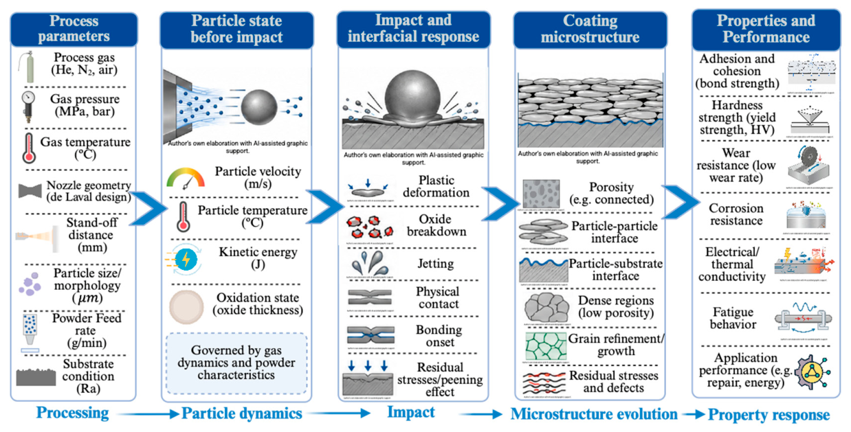
Figure 2.
Relevant aspects of different surface preparation approaches for CS repair. Created in ChatGPT (OpenAI, 2026).
Figure 2.
Relevant aspects of different surface preparation approaches for CS repair. Created in ChatGPT (OpenAI, 2026).
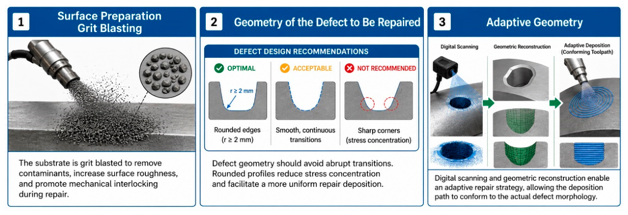
Figure 3.
Limitations and strengths of CSAM. Created in ChatGPT (OpenAI, 2026).
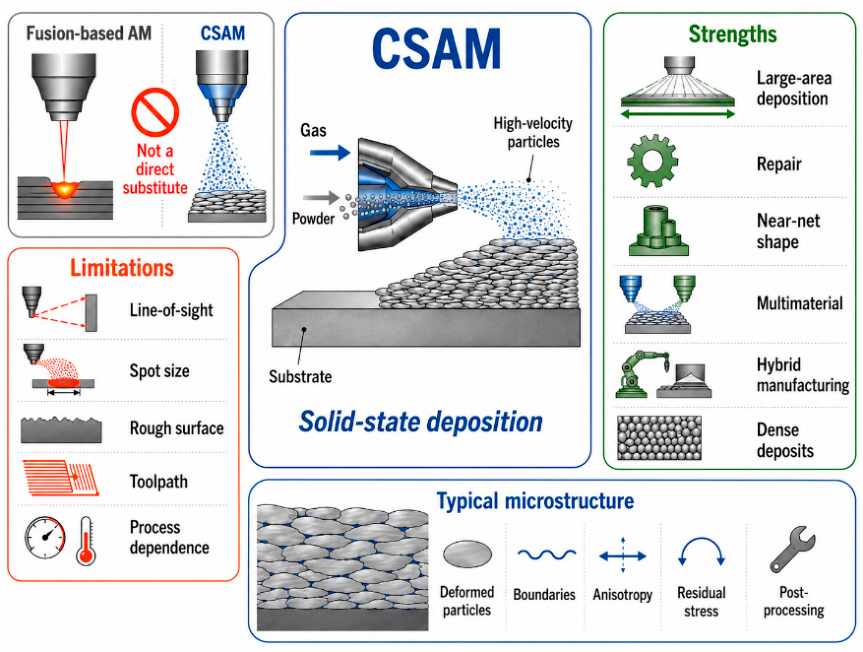
Figure 4.
Magnus force in CS. Created in ChatGPT (OpenAI, 2026).
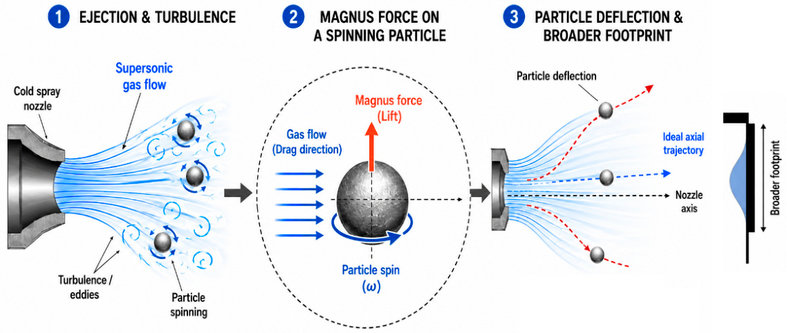
Figure 5.
Schematic representation of differences between traditional raster strategy and metal knitting strategy. Created in ChatGPT (OpenAI, 2026).
Figure 5.
Schematic representation of differences between traditional raster strategy and metal knitting strategy. Created in ChatGPT (OpenAI, 2026).
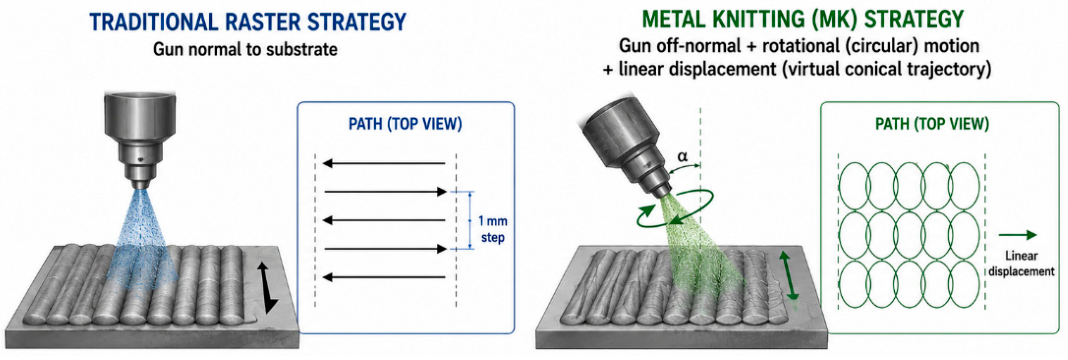
Figure 6.
(a) bidirectional strategy, and (b) cross-hatching strategy. Adapted from [55].
Figure 6.
(a) bidirectional strategy, and (b) cross-hatching strategy. Adapted from [55].
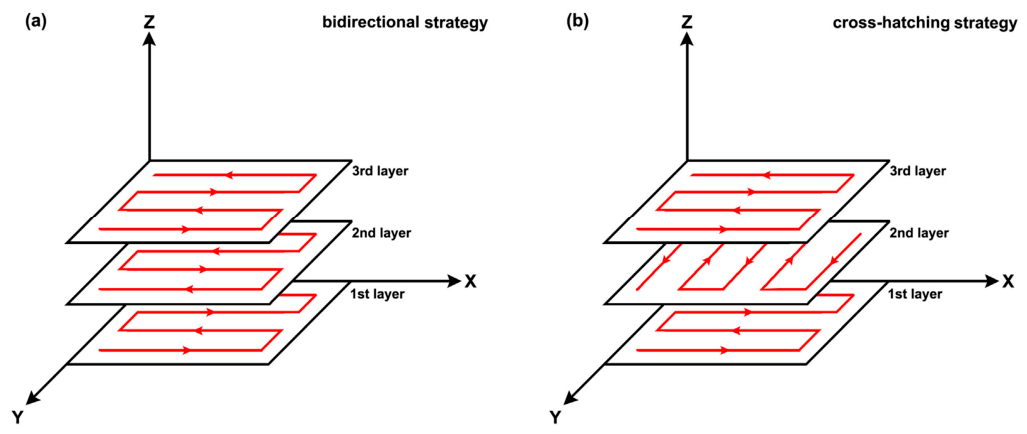
Figure 7.
Schematics of four layer-by-layer scanning strategies with (a) zigzag path, (b) cross path, (c) parallel path and (d) spiral path. Adapted from [56].
Figure 7.
Schematics of four layer-by-layer scanning strategies with (a) zigzag path, (b) cross path, (c) parallel path and (d) spiral path. Adapted from [56].
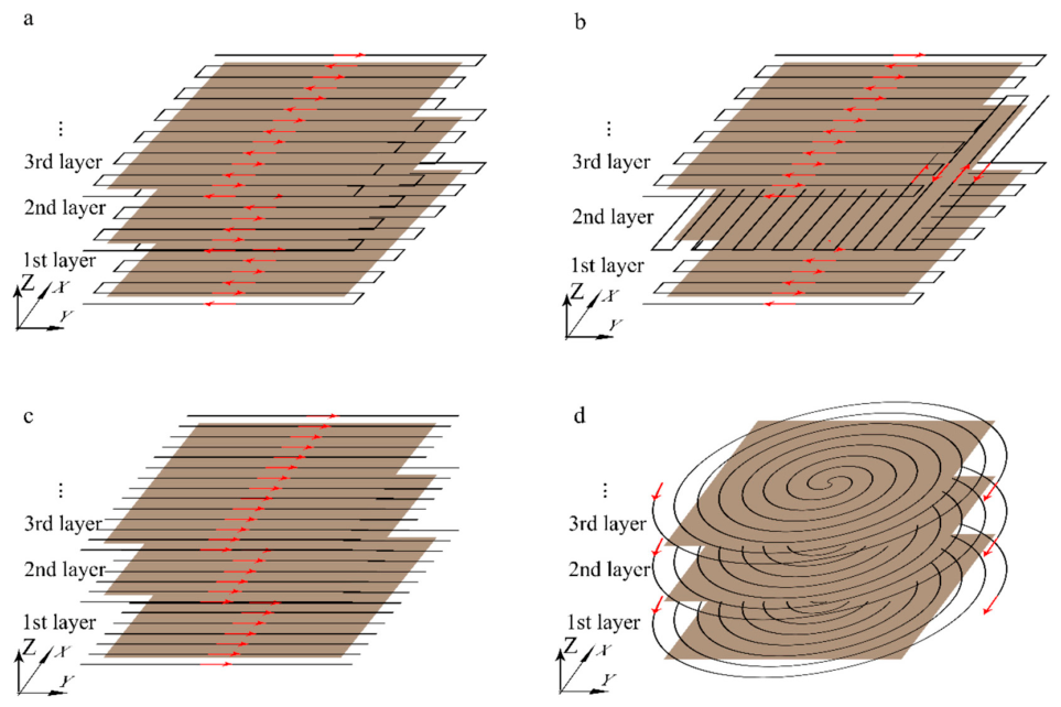
Figure 8.
Schematic representation of intelligent process optimization path in CSAM. Created in ChatGPT (OpenAI, 2026).
Figure 8.
Schematic representation of intelligent process optimization path in CSAM. Created in ChatGPT (OpenAI, 2026).
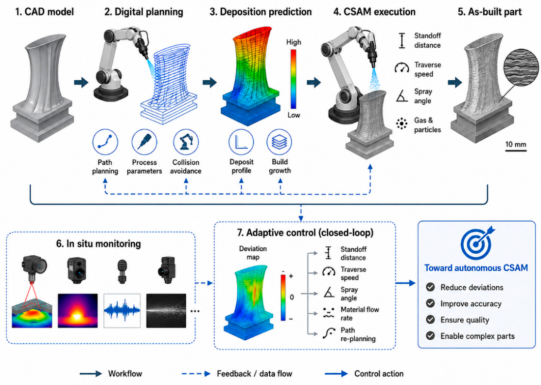
Figure 9.
Models in Digital CSAM. Created in ChatGPT (OpenAI, 2026).
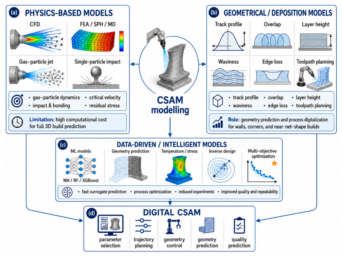
Figure 10.
Compatibilities of CSAM. Created in ChatGPT (OpenAI, 2026).
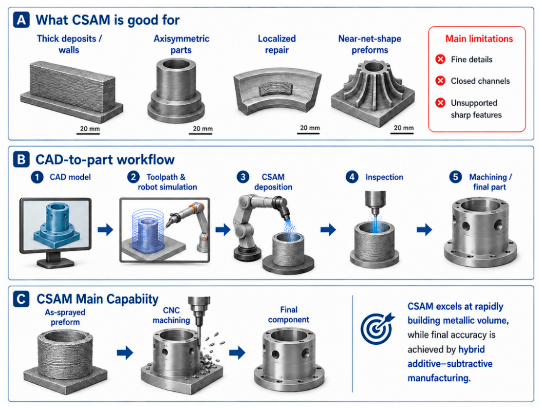
Figure 11.
Cold spray repair workflow. Created in ChatGPT (OpenAI, 2026).
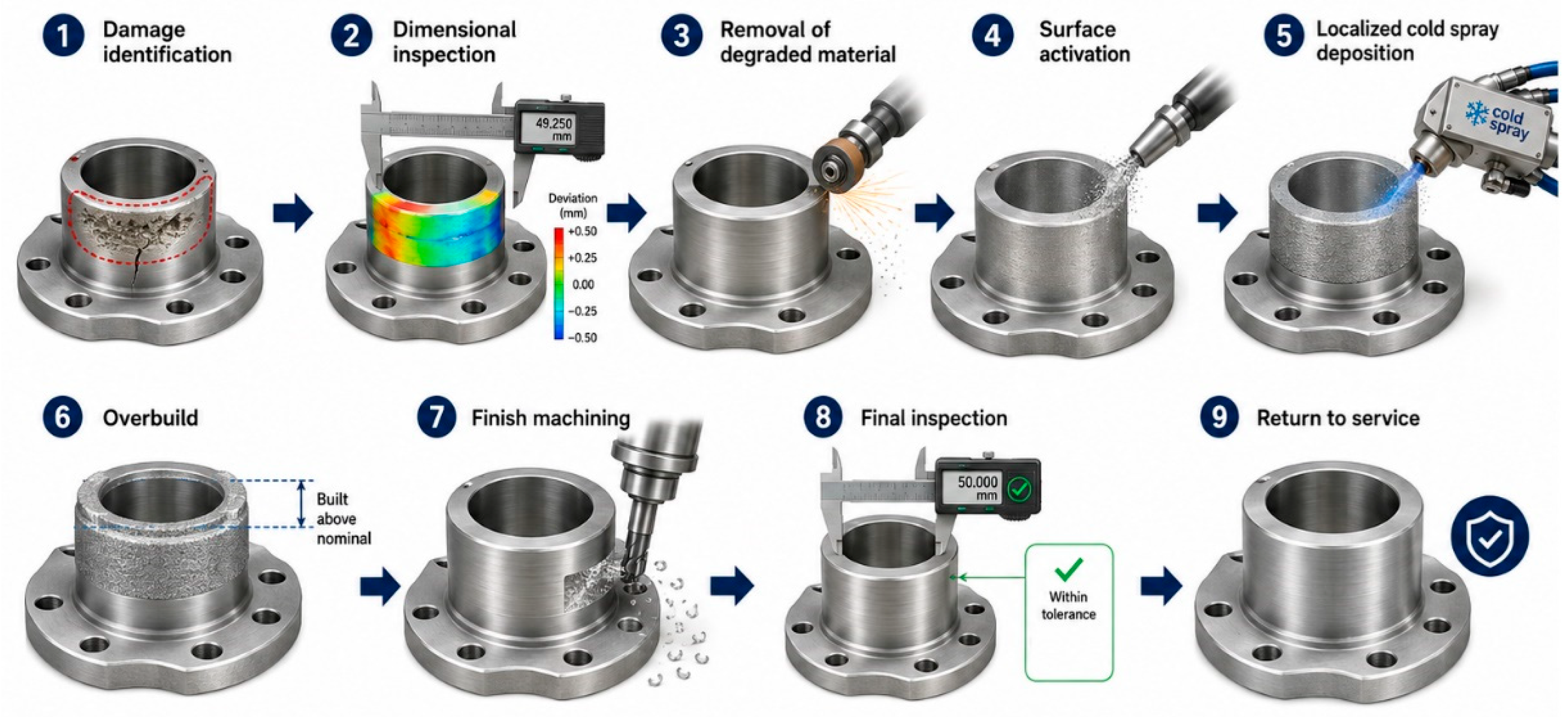
Figure 12.
On-aircraft cold spray repair of a B-1B Lancer at Dyess Air Force Base (Feb. 20, 2026) [109].
Figure 12.
On-aircraft cold spray repair of a B-1B Lancer at Dyess Air Force Base (Feb. 20, 2026) [109].
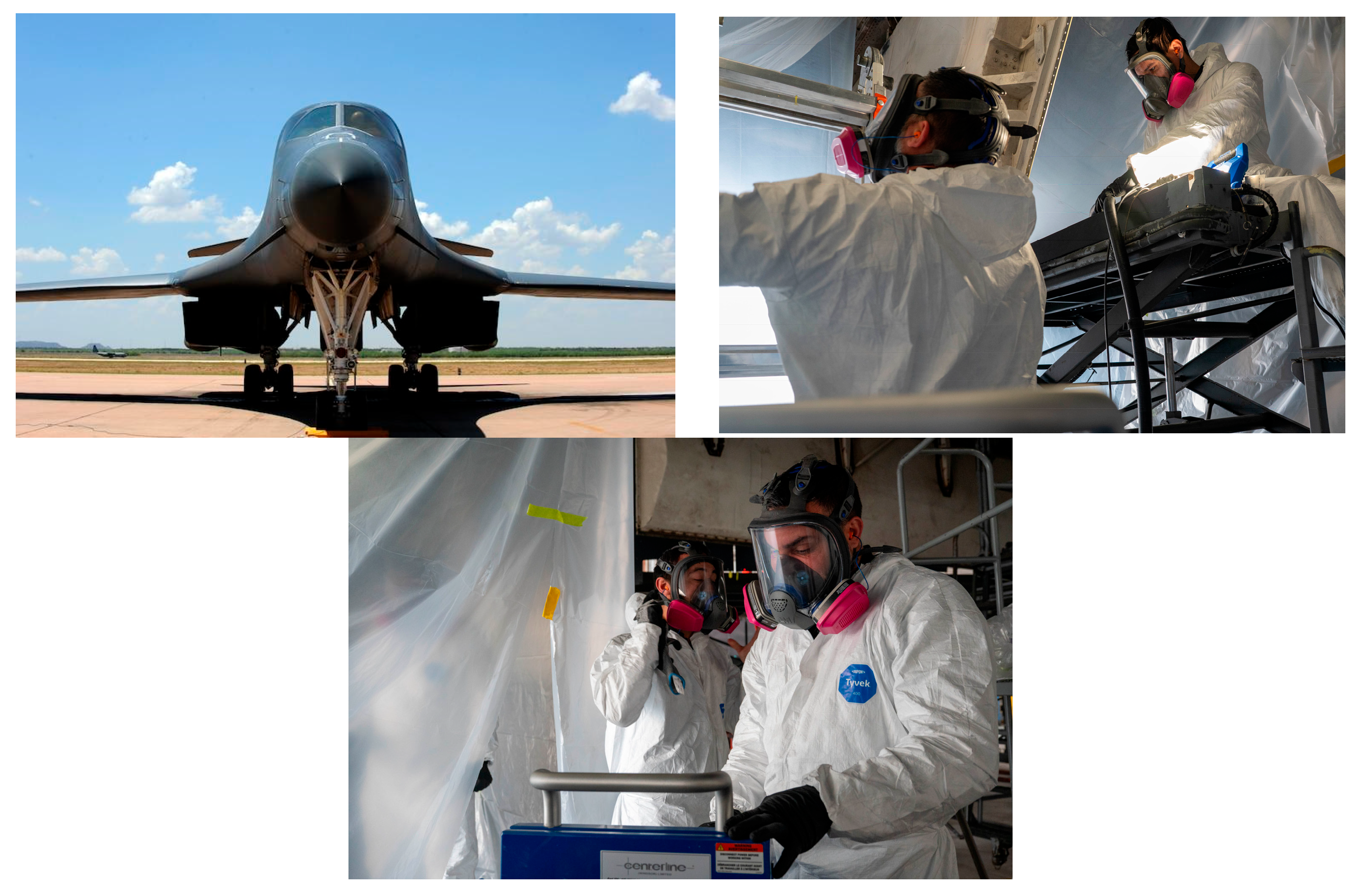
Figure 13.
Smart repair process workflow. Courtesy of CSIRO – continuous3D.
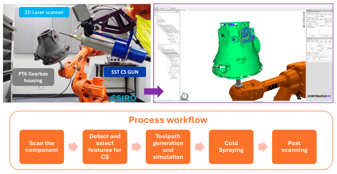

Table 1.
Comparative overview of process gases employed in cold spray.
| Process gas | Particle velocity | Main advantage | Main limitation | Typical use |
| Helium (He) | Very high | Provides the highest particle acceleration; improves deposition of materials with high critical velocity; promotes dense coatings and strong adhesion. |
High cost, limited availability, and high gas consumption; less practical for large-area or routine industrial production. |
Ti alloys, stainless steels, Ni-based superalloys, and other difficult-to-spray materials. |
| Nitrogen (N2) | Medium-high | Good balance between performance, availability, and cost; relatively inert; widely used in high-pressure industrial systems. | Lower acceleration capability than He; may be insufficient for high-strength or low-ductility materials without optimized pressure, temperature, or nozzle design. |
Al, Cu, Zn, Ni, some steels and industrial coatings |
| Compressed air | Low-medium | Low cost, simple operation, and high availability; suitable for low-pressure cold spray and less demanding applications. | Higher oxidation risk and lower particle acceleration; unsuitable for oxygen-sensitive materials or coatings requiring high interfacial quality. | Low-pressure systems, repair coatings, and low-cost surface modification. |
| He/N2 mixture | High | Intermediate option between He and N2; improves particle velocity compared with pure N2 while reducing dependence on pure He. | Requires optimization of gas ratio and process parameters; it is still more expensive than N2 and performance depends strongly on system configuration. | Difficult-to-spray materials where pure He is not economically viable. |
Disclaimer/Publisher’s Note: The statements, opinions and data contained in all publications are solely those of the individual author(s) and contributor(s) and not of MDPI and/or the editor(s). MDPI and/or the editor(s) disclaim responsibility for any injury to people or property resulting from any ideas, methods, instructions or products referred to in the content. |
© 2026 by the authors. Licensee MDPI, Basel, Switzerland. This article is an open access article distributed under the terms and conditions of the Creative Commons Attribution (CC BY) license (http://creativecommons.org/licenses/by/4.0/).
Copyright: This open access article is published under a Creative Commons CC BY 4.0 license, which permit the free download, distribution, and reuse, provided that the author and preprint are cited in any reuse.