

Submitted:
25 August 2026
Posted:
26 August 2026
You are already at the latest version
Abstract
The virtual synchronous generator serves as a critical interface between renewable generation systems and the grid, providing inertia to support both active and reactive power. Based on the duality principle, a virtual permanent-capacitor synchronous generator is derived to enhance the inertia of the three-phase current-source inverter, exhibiting dynamic characteristics similar to those of a virtual permanent-magnet synchronous generator. Additionally, this work presents a unified virtual synchronous generator model applicable to both voltage-source and current-source topologies. By constructing a suitable Lyapunov function candidate, the stability criteria of the unified model under standalone operation are established. In grid-connected mode, a frequency-locking condition is derived to ensure synchronization of the virtual synchronous generators with the grid. Eigenvalue analysis is employed to assess the stability of the unified model under frequency-locking conditions. The correctness of the derived stability conditions in standalone and grid-connected modes is confirmed through time-domain simulations.
Keywords:
virtual synchronous generator
; virtual permanent-magnet synchronous generator
; virtual permanent-capacitor synchronous generator
; voltage-source inverter
; current source inverter
; stability analysis
1. Introduction
Virtual synchronous generators (VSGs) are widely adopted in renewable generation systems to provide virtual inertia for supporting grid voltage and frequency [1]. Two primary control strategies are derived from the PQ dynamics and synchronous generator dynamic equations, respectively [1,2,3,4,5]. The former employs second-order PQ dynamics to regulate active and reactive power for grid frequency and voltage stabilization; however, it cannot fully replicate the dynamic characteristics of synchronous generators. In contrast, the latter serves as a prominent inertia emulation approach that comprehensively captures flux linkage dynamics, the swing equation, and additional electromechanical transients.
VSGs are classified into voltage-controlled and current-controlled types, which function as voltage sources and current sources, respectively [6]. Voltage-controlled VSGs are better suited to weak grids, whereas current-controlled VSGs perform better in strong grids. Conventional voltage-controlled VSGs are based on the mathematical model of synchronous generators, incorporating stator voltage dynamics, flux linkage equations, and mechanical torque relationships [7,8,9,10].
To further simplify the control strategy, a permanent-magnet synchronous generator (PMSG) model can be adopted for VSG implementation, requiring fewer equations while preserving essential dynamic characteristics [11]. However, under strong grid conditions, voltage-source inverter (VSI)-based VSGs may induce instability. Although current-controlled VSGs have been proposed to mitigate this issue, they remain inherently reliant on VSIs, whose fundamental voltage-output nature imposes limitations on current regulation fidelity [12,13,14]. Moreover, the phase-locked loop (PLL), an essential component of conventional voltage-controlled VSGs, can itself become a source of instability [15,16].
Given the duality between voltage-source inverters (VSIs) and current-source inverters (CSIs) illustrated in Figure 1 [17,18], a CSI-based VSG can be derived as the dual counterpart to the virtual permanent-magnet synchronous generator (VPMSG). Therefore, leveraging the three-phase CSI topology shown in Figure 1(b), this paper proposes the virtual permanent-capacitor synchronous generator (VPCSG) in Section 2. The duality between the VPMSG and the VPCSG is further elaborated. Section 3 establishes a unified mathematical model that encompasses both the VPMSG and the VPCSG. Section 4 derives the stability condition for the unified model in standalone mode via a Lyapunov function candidate, and applies eigenvalue analysis to assess its grid-connected stability. The frequency-locking condition is also derived in this section. Subsequently, Section 5 validates the dynamic stability of both the VPMSG and the VPCSG through time-domain simulations.
2. Derivation of the Virtual Permanent-Capacitor Synchronous Generator Model
Following the space vector formulation of PMSG stator voltage equations in [19,20,21], the VPMSG counterpart is derived analogously as:
Here, the virtual stator voltage, current and flux vectors are defined as
where va, vb and vc are the virtual phase voltages; ia, ib and ic are the virtual phase currents; Ls, ψr and θe are the virtual stator inductance, the virtual flux amplitude and the virtual electrical angle of the rotor, respectively. θe=ωet where ωe is the virtual electrical angular frequency of the rotor. ωe=npωm where ωm and np is the virtual mechanical angular frequency and the virtual number of pole pairs, respectively. By the duality principle [22], dual circuits share identical mathematical structures; thus, the dual of Equation (1) is expressed as:
The duality correspondence between Equations (1) and (5) is summarized in Table 1.
Here, the dual counterparts of the virtual stator voltage, current, and flux vectors—namely, the current, voltage, and charge vectors—are defined as follows:
Henceforth, the hat symbol (ˆ) denotes dual quantities. , and are the dual phase currents; , and are the dual phase voltages; , and are the dual capacitance, the dual charge amplitude and the dual electrical angle, respectively. where denotes the dual electrical angular frequency. Projecting the abc-frame space vectors onto the dq frame yields the dq-axis current and voltage components, namely,
Here, and are the dq-axis components of the dual current vector; and are the dq-axis components of the dual voltage vector.
Substituting Equation (8) into Equation (5) yields
Multiplying Equation (11) by yields
Differentiating Equation (10) with respect to t yields
Substituting Equation (13) into Equation (12) yields
Equations (9) and (10) are substituted into Equation (14), giving
The dual torque equation for the VPMSG is given by
Here, J, , Tm, and Bf are the virtual total inertia, the virtual electromagnetic torque, the virtual mechanical torque and the virtual viscous friction coefficient, respectively; where is the dual mechanical angular frequency.
Multiplying Equation (8) by yields
Thus,
The output electrical power is given by
In Equation (19), the first term represents the virtual input mechanical power, the second term denotes the capacitive power stored in the electric field, and the third term accounts for the power losses. The virtual input mechanical power is defined as
Thus, the virtual electromagnetic torque is defined as
Equations (15), (16) and (21) form the VPCSG model, which has a mathematical structure similar to that of the VPMSG. Thus, the VPCSG replicates dominant dynamic characteristics of the VPMSG when the dual operating parameters are set to identical values. Finally, the duality mappings between the VPMSG and VPCSG are summarized in Table 2. Depending on the circuit topology, the swing equations listed in Table 2 are either emulated through virtual inertia control or physically realized via the actual electromechanical dynamics of the circuit. However, implementing the virtual swing equation increases control complexity due to additional state variables and tuning parameters, whereas the physical electromechanical swing equation inherently simplifies controller design by leveraging natural system dynamics. For the topologies shown in Figure 1, the dc-link capacitor equation of the VSI and the dc-link inductor equation of the CSI serve as the respective swing equations. Therefore, explicit implementation of the swing equation in the control strategy becomes unnecessary.
Thus, the duality between VPMSG and VPCSG for the topologies in Figure 1 is summarized in Table 3. Here, idc and vdc denote the input current and capacitor voltage of the VSI, respectively; and denote the inductor current and input voltage of the CSI, respectively.
To derive control strategies for the VPMSG and the VPCSG, the dynamic equations of the VSI and CSI in Figure 1 are formulated as follows.
VSI: (22)
CSI: (23)
Here, ud and uq are the dq-axis components of the output voltages of the VSI in Figure 1(a); and are the dq-axis output current components of the CSI in Figure 1(b).
Comparison of Table 2 and Table 3 with Equations (22) and (23) shows that the VSI and CSI are equivalent to the VPMSG and VPCSG under the following control strategies:
VPMSG: ud*=0 and uq*= npψrvdc (24)
VPCSG: and (25)
Here, ud* and uq* represent the dq-axis reference voltages of the VSI; and denote the dq-axis reference currents of the CSI; np, ψr and denote the control parameters. The control strategies for the VPMSG and VPCSG, given by Equations (24) and (25), are implemented via the SPWM modulation applied to the VSI and CSI in Figure 2. The corresponding dq-frame circuit equivalent models are derived as shown in Figure 3, confirming consistency with the models in Table 2 and Table 3. Here, ,
3. A Unified Modeling and Analysis Framework for Virtual Synchronous Generators
VPMSG:
VPCSG:
Through the following transformations:
VPMSG: and (26)
VPCSG: and (27)
the unified model is derived as follows:
where τ1=Ls/Rs, , , , , , , , and for VPMSG; , , ,, , , , and for VPCSG.
Furthermore, setting the time derivative in Equation (28) to zero yields the equilibrium point:
where ξ* is the solution of the following equation:
According to the cubic formula [23], the solutions of Equation (30) can be analytically derived as follows:
where , , , and , , and . Therefore, three equilibria E1*, E2* and E3* correspond to ξ1*, ξ2* and ξ3*, respectively. When , the unified model (28) admits at least two distinct real equilibria; otherwise, it has a unique equilibrium.
In grid-connected mode, the grid parameters are specified as follows:
Grid-Side voltages of the VPMSG: va=Umsin(ωgt+θv), vb=Umsin(ωgt+θv−2/3π) and vc=Umsin (ωgt+θv+2/3π), where θv, ωg and Um are the initial angle, electrical angular frequency and amplitude of the grid voltages. Here, ωg=2πfg, fg denotes the grid frequency;
Grid-side currents of the VPCSG: , and , where θi and Im are the initial angle and amplitude of the grid currents, respectively.
Applying the Park transformation yields:
for the VPMSG and
for the VPCSG.
Whether the dq-frame grid voltages and currents are constant or time-varying depends on the relationship between ωg and ωe (or ωg and ). Standalone mode is a special case of grid-connected operation where ωg=ωe for the VPMSG and ωg = for the VPCSG; consequently, vd, vq, and remain constant. Therefore, the stability of both the VPMSG and the VPCSG is analyzed under standalone and grid-connected modes.
3.1. Standalone Mode
3.1.1. Λd=Λq=Γm=0
By removing all excitation terms, Equation (28) simplifies to
Setting the time derivative in Equation (32) to zero yields the equilibrium point:
The Jacobian matrix is given by
Solving the characteristic equation det(λI−Jac)=0 yields the eigenvalues:
The signs of the eigenvalues are analyzed as follows:
CASE 1: (σ−1)2−4γσ≥0
λ2 and λ3 are real eigenvalues. Since λ2×λ3=σ(1+γ)>0 and λ2+λ3=−(σ+1)<0, both λ2 and λ3 are negative real numbers.
CASE 2: (σ−1)2−4γσ<0
λ2 and λ3 form a complex conjugate pair with negative real parts since –(1+σ)/2<0.
Therefore, all eigenvalues have negative real parts, implying local asymptotic stability of the equilibrium point. The representative phase trajectory of system (32) is plotted in Figure 4.
3.1.2. Λd≠0, Λq≠0 and Γm≠0
In standalone mode, it can be concluded that ωg=ωe for the VPMSG and ωg= for the VPCSG, so we can have Λd=constant and Λq=constant. For convenience of analysis, by applying the following transformations:
, ,
Equation (28) is recast into the following dynamical system:
Choose the Lyapunov function candidate as:
Here, =(,,)T, p>0, q>0, r=q/p and
So, the time derivative of can be derived as:
Here,
The equilibrium point is globally asymptotically stable if is negative definite, which requires all leading principal minors of Q to be positive. The first leading principal minor Q1=2p>0, The second leading principal minor is Q2=4p2>0, and the third leading principal minor is
Consequently, the stability condition is established as follows:
It is known that , so we have
Therefore, when Ξ>0, the unified system is locally asymptotically stable at the equilibrium point . The representative phase trajectory of the system (28) is plotted in Figure 5.
3.2. Grid-Connected Mode
In grid-connected mode, Equation (28) can be rewritten as:
where , θ0=θv and for the VPMSG; , θ0=θi and for the VPCSG.
In steady state, the angular frequency in (36) is synchronized with the grid angular frequency; thus, . Therefore, the following conditions are satisfied:
, and
Substitution of into yields
Furthermore, by setting and , it is derived that
So,
Substituting the first expression in (38) into the second yields
From Equation (39), the initial angle θ0 admits two analytical solutions:
Substituting Equation (37) into Equation (39) yields
Equation (40) gives the necessary condition for the angular frequency of the unified model to be locked to the grid angular frequency, as illustrated for the VPMSG and the VPCSG in Figure 6. It can be seen that the regions corresponding to should appear among the regions with Π≤1. However, when Π≤1, the stability of the unified model requires further discussion, as follows.
In the frequency-locked state, the equilibrium point of the grid-connected unified system (36) can be rewritten as
Here, there are two equilibrium points E1* and E2* corresponding to θ0(1) and θ0(2).
Therefore, the Jacobian matrix can be obtained as
The characteristic equation is derived as
Here, , , .
Applying the cubic formula, the eigenvalues are analytically obtained as follows:
where and , , and . Providing that all eigenvalues possess negative real parts, the system is asymptotically stable.
4. Numerical Simulations
Without loss of generality, the operating parameters of the unified model are chosen as follows: Ls=2mH, Rs=200mΩ, C=470μF and G=2.1S for the VPMSG; , , and for the VPCSG. To verify the stability of the unified model, the system is analyzed in standalone mode and grid-connected mode, respectively.
3.1. Standalone Mode
Based on Equation (35), Ξ is calculated as 223.5>0 for the VPMSG and 20.6>0 for the VPCSG, so they are stable. The typical waveforms are shown in Figure 9. As observed, the output three-phase currents and voltages are symmetrical, and the output angular frequency is stabilized at fg=50Hz for both generators.
3.2. Grid-Connected Mode
Under the control strategies (24) and (25), the VSI and the CSI function as the VPMSG and the VPCSG, respectively. When the unified model (36) falls within the frequency-locked regions shown in Figure 6, its stability must be further verified through eigenvalue analysis to ensure that the VSG outputs stable three-phase currents or voltages. According to Equation (44), the real part of the rightmost eigenvalue λmax is numerically computed as a function of Um and Im, as illustrated in Figure 10. Therefore, when Π<1 and Re(λmax)<0, the system is stabilized at the grid frequency fg=50Hz. The typical waveforms are illustrated in Figure 11. Obviously, the electrical angular frequency ωe can maintain synchronization with the grid frequency across a broad operating range of Um and Im.
5. Conclusions
The VSI and CSI are dual topologies that share a similar mathematical model. Under specific control conditions, the VSI is mathematically equivalent to a VPMSG; likewise, the CSI is mathematically equivalent to a VPCSG. Therefore, the VPMSG and VPCSG form a pair of dual VSGs that share an analogous mathematical model. A unified dimensionless model can be established to characterize their dynamic behaviors. By selecting an appropriate Lyapunov function candidate, the stability conditions for the unified system in standalone mode are analytically derived. Through eigenvalue analysis, the stability conditions for the unified model in grid-connected mode are also derived. Nevertheless, grid-connected operation necessitates that the VSGs remain locked to the grid frequency. Both frequency synchronization and stability conditions must be simultaneously satisfied to enable grid connection of the VSGs.
Author Contributions
Conceptualization, D.W.; methodology, D.W.; software, D.W.; validation, D.W.; formal analysis, D.W.; investigation, D.W.; resources, D.W. and Y.T.; data curation, D.W. and Y.Y.; writing—original draft preparation, D.W.; writing—review and editing, D.W.; visualization, D.W. and Y.Y.; supervision, D.W. and H.G.; project administration, D.W. and X.Y.; funding acquisition, D.W. and X.L.. All authors have read and agreed to the published version of the manuscript.
Funding
This work was supported by Hunan Provincial Natural Science Foundation of China (Grant No. 2025JJ80254), Research Start-up Fund Project at Hunan Institute of Technology (Grant No. HQ24036), Hunan Provincial Science and Technology Innovation Program Project (Grant No. HS823951386), Hengyang Municipal Science and Technology Program Project (Grant No. 202440017322), Hunan Province College Students Research Learning and Innovative Experiment Project (Grant Nos. S202611528314X and S202611528253).
Data Availability Statement
The original contributions presented in the study are included in the article, further inquiries can be directed to the corresponding author.
Conflicts of Interest
The authors declare no conflicts of interest.
Abbreviations
The following abbreviations are used in this manuscript:
| VPMSG | Virtual permanent-magnet synchronous generator |
| VPCSG | Virtual permanent-capacitor synchronous generator |
| VSG | Virtual synchronous generator |
| VSI | Voltage-source inverter |
| CSI | Current-source inverter |
References
- Zhong, Q.C. Power Electronics-Enabled Autonomous Power Systems: Next Generation Smart Grids; John Wiley & Sons Ltd: Hoboken, NJ, USA, 2020; pp. 51–79. [Google Scholar]
- Brambilla, A.M.; Giudice, D.; Bizzarri, F. Improved stability of a grid-following converter controller supplying virtual inertia and damping. IEEE Trans. Power Del. 2025, 40, 900–911. [Google Scholar] [CrossRef]
- Alizadeh, M.; Sun, W. Dynamic interactions between inverter-based resources and synchronous generators: a comparative study for cascading failure risk. IEEE Access 2025, 13, 102830–102847. [Google Scholar] [CrossRef]
- Meng, Q.; Ren, Y.; Liu, H. Frequency stability analysis of grid-forming PMSG based on virtual synchronous control. IEEE Access 2024, 12, 84134–84148. [Google Scholar] [CrossRef]
- Meng, Z.; Xing, X. Stability analysis and parameters optimization of the voltage control loop in virtual synchronous generators. IEEE Trans. Energy Convers Early Access., 2026. [Google Scholar]
- Wu, W.; Chen, Y.; Zhou, L.; Luo, A.; Zhou, X.; He, Z.; Yang, L.; Xie, Z.; Liu, J.; Zhang, M. Sequence impedance modeling and stability comparative analysis of voltage-controlled VSGs and current-controlled VSGs. IEEE Trans. Ind. Electron. 2019, 66, 6460–6472. [Google Scholar] [CrossRef]
- Zhang, Z.; Guo, H.; Xu, Z. Synchronous machine imitation control of MMC Stations adaptable for both strong and weak grids. IEEE Trans. Power Del. 2025, 40, 912–926. [Google Scholar] [CrossRef]
- Mishra, T.; Kalke, D.; Gurrala, G.; Padhi, R. Synchronous generator emulation using output matching control through feedback linearization. IEEE Trans. Energy Convers. 2025, 40, 2191–2204. [Google Scholar] [CrossRef]
- Yin, H.; Kustanovich, Z.; Lin, J.; Weiss, G. Synchronverters with damper windings to attenuate power oscillations in grids. IEEE J. Emerg. Sel. Top. Ind. Electron. 2024, 5, 1376–1387. [Google Scholar] [CrossRef]
- Yin, H.; Wang, S.; Zhou, Z. Synchronverters with a virtual oscillator to attenuate power oscillations. IEEE J. Emerg. Sel. Top. Power Electron. 2024, 12, 1303–1310. [Google Scholar] [CrossRef]
- Arghir, C.; Dörfler, F. The electronic realization of synchronous machines: model matching, angle tracking, and energy shaping techniques. IEEE Trans. Power Electron. 2020, 35, 4398–4410. [Google Scholar] [CrossRef]
- Rosso, R.; Wang, X.; Liserre, M.; Lu, X.; Engelken, A.S. Grid-Forming converters: control approaches, grid-synchronization, and future trends—a review. IEEE Open J. Ind. Appl. 2021, 2, 93–109. [Google Scholar] [CrossRef]
- Hong, Z.; Xu, H.; Hou, Z.; Zhan, M. Origin of anomalous instability of grid-forming converters tied to stiff grid. IET Renew. Power Gener. 2023, 17, 2563–2574. [Google Scholar] [CrossRef]
- Li, X.; Xiong, X.; Li, C.; Zhou, Z. Analysis on instability mechanism of grid- connected VSG under strong grid condition. Proceedings of 2024 IEEE 10th International Power Electronics and Motion Control Conference, Chengdu, China, 17-20 May 2024. [Google Scholar]
- Yu, Y.; Chaudhary, S. K.; David, G.; Tinajero, A.; Xu, L.; Bakar, N. N. B. A.; Vasquez, J. C.; Guerrero, J. M. A reference-feedforward-based damping method for virtual synchronous generator control. IEEE Trans. Power Electron. 2022, 37, 7566–7571. [Google Scholar] [CrossRef]
- Li, M.; Yu, P.; Hu, W.; Wang, Y.; Shu, S.; Zhang, Z.; Blaabjerg, F. Phase feedforward damping control method for virtual synchronous generators. IEEE Trans. Power Electron. 2022, 37, 9790–9806. [Google Scholar] [CrossRef]
- Dahono, P.A.; Kataoka, T.; Sato, Y. Dual relationships between voltage-source and current-source three-phase inverters and its applications. Proceedings of Second International Conference on Power Electronics and Drive Systems, Singapore, 26-29 May 1997. [Google Scholar]
- Li, Y.; Li, Y.W. Power converters topological transformation using dual and isomorphic principles. IEEE Open J. Power Electron. 2020, 1, 74–87. [Google Scholar] [CrossRef]
- Chapman, S.J. Electric Machinery Fundamentals, 5th ed.; McGraw-Hill: New York, NY, USA, 2012; pp. 191–270. [Google Scholar]
- Wu, B.; Lang, Y.; Zargari, N.; Kouro, S. Power Conversion and Control of Wind Energy Systems; Wiley-IEEE Press: Hoboken, USA, 2011. [Google Scholar]
- Wang, L.; Chai, S.; Yoo, D.; Gan, L.; Ng, K. PID and Predictive Control of Electrical Drives and Power Converters Using Matlab®/Simulink®; Wiley-IEEE Press: Singapore, 2015. [Google Scholar]
- Desoer, C. A.; Kuh, E. S. Basic Circuit Theory; McGraw-Hill: New York, NY, USA, 1969; Volume pp. 219-228, pp. 444–457. [Google Scholar]
- Spiegel, M.R.; Lipschutz, S.; Liu, J. Mathematical Handbook of Formulas and Tables, 5th ed.; McGraw-Hill: New York, NY, USA, 2018; p. 13. [Google Scholar]
Figure 1.
Topologies of the VSGs: (a) VSI. (b) CSI.
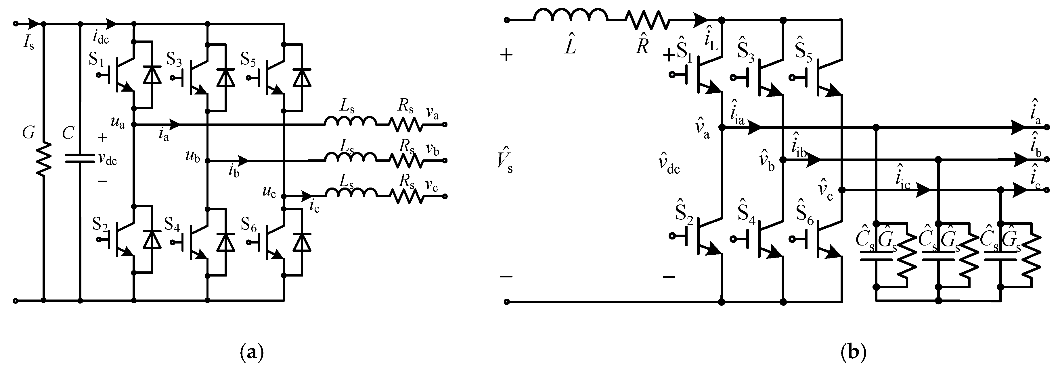
Figure 2.
Control strategies for the VSI and CSI: (a) VPMSG. (b) VPCSG.
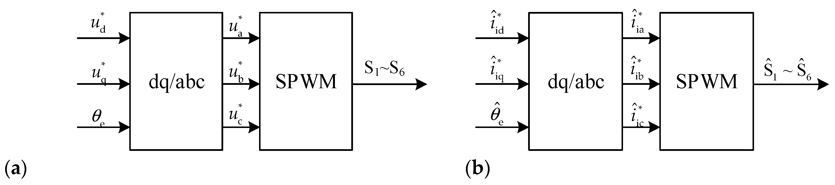
Figure 3.
Circuit equivalent models: (a) VPMSG. (b) VPCSG.
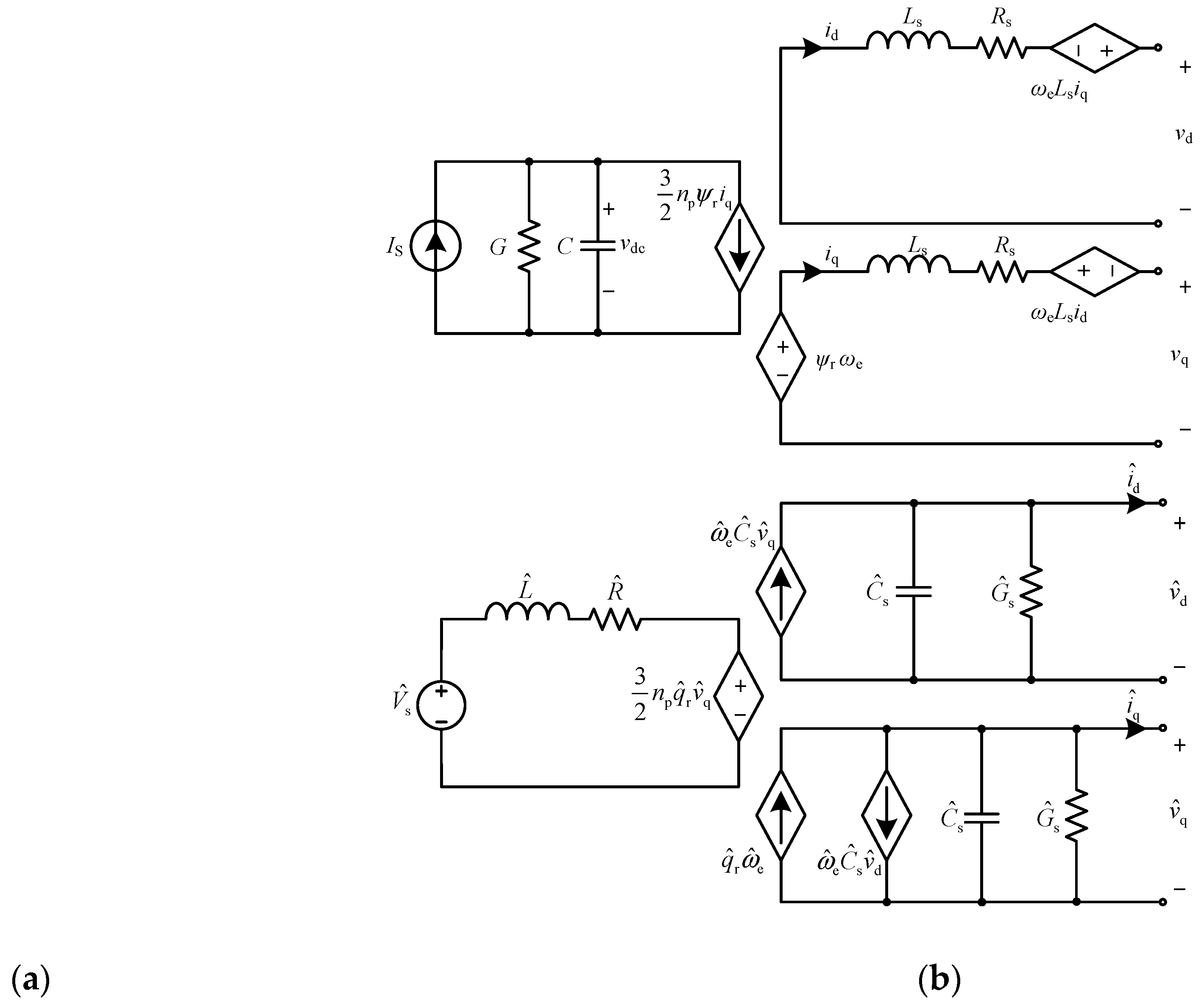
Figure 4.
Phase trajectory of the unified model with γ= 44.76 and σ= 44.68.
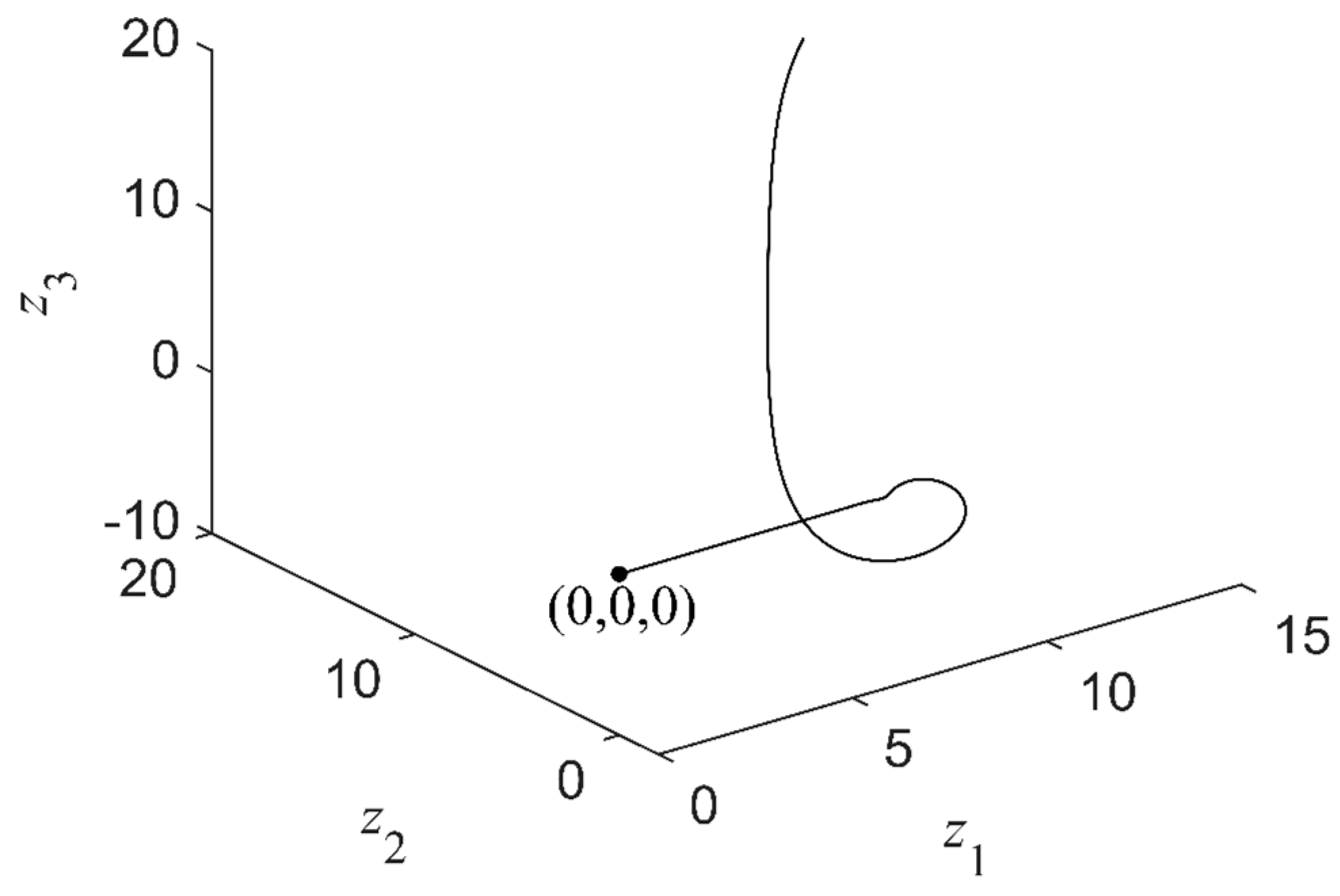
Figure 5.
Phase trajectory of the unified model with γ=44.76, σ=44.68, Λd= 3.12, Λq=181.9 and Γm=11.3.
Figure 5.
Phase trajectory of the unified model with γ=44.76, σ=44.68, Λd= 3.12, Λq=181.9 and Γm=11.3.
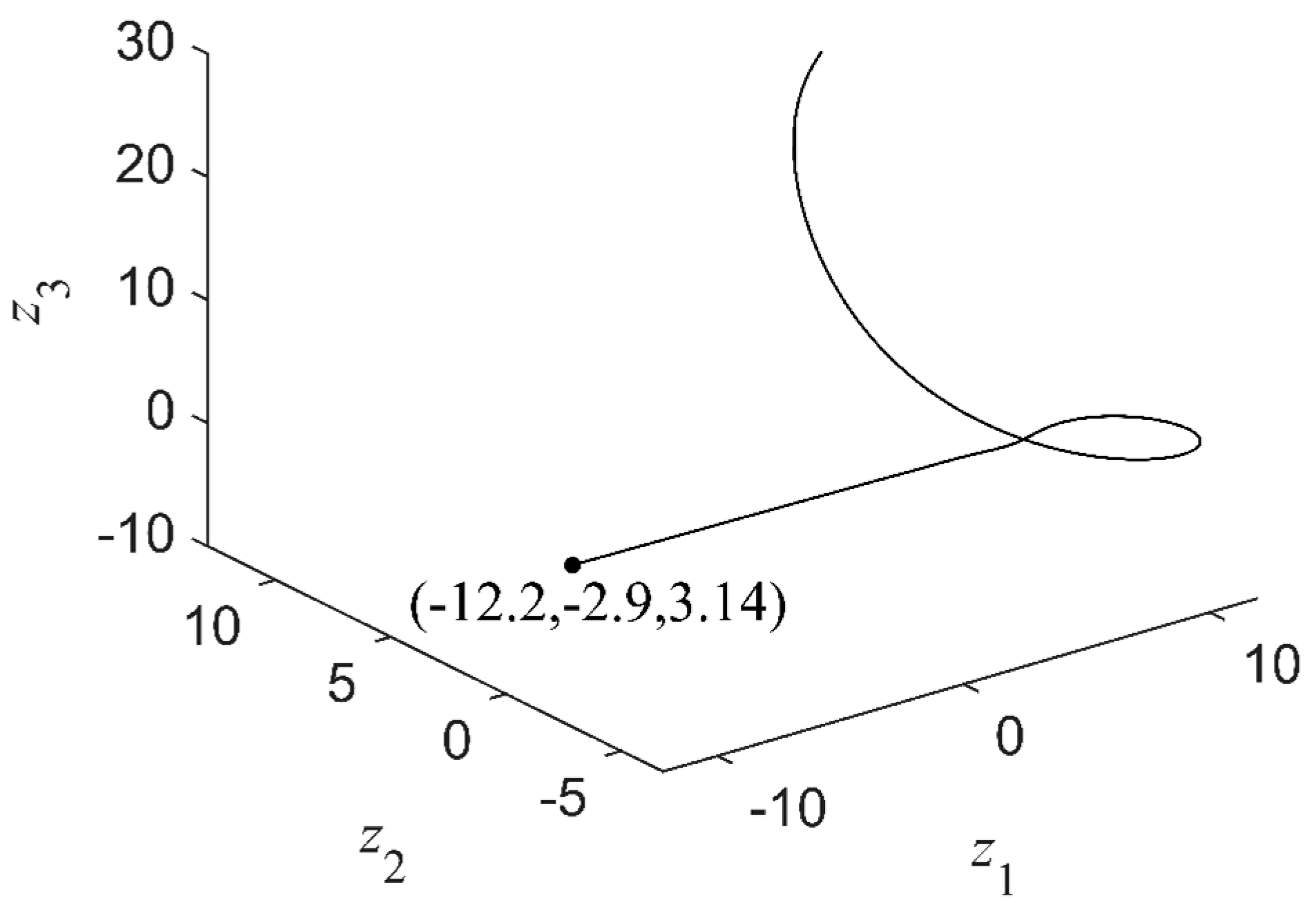
Figure 6.
Frequency-locked regions of the unified model. (a) VPMSG with γ= 44.76, σ=44.68, Θm=128.7, Γm=11.3, and θ0=θ0(2)=3.25. (b)VPCSG with γ=3.1, σ=0.02, Θm=1.27, Γm=0.02, and θ0=θ0(2)=3.35.
Figure 6.
Frequency-locked regions of the unified model. (a) VPMSG with γ= 44.76, σ=44.68, Θm=128.7, Γm=11.3, and θ0=θ0(2)=3.25. (b)VPCSG with γ=3.1, σ=0.02, Θm=1.27, Γm=0.02, and θ0=θ0(2)=3.35.
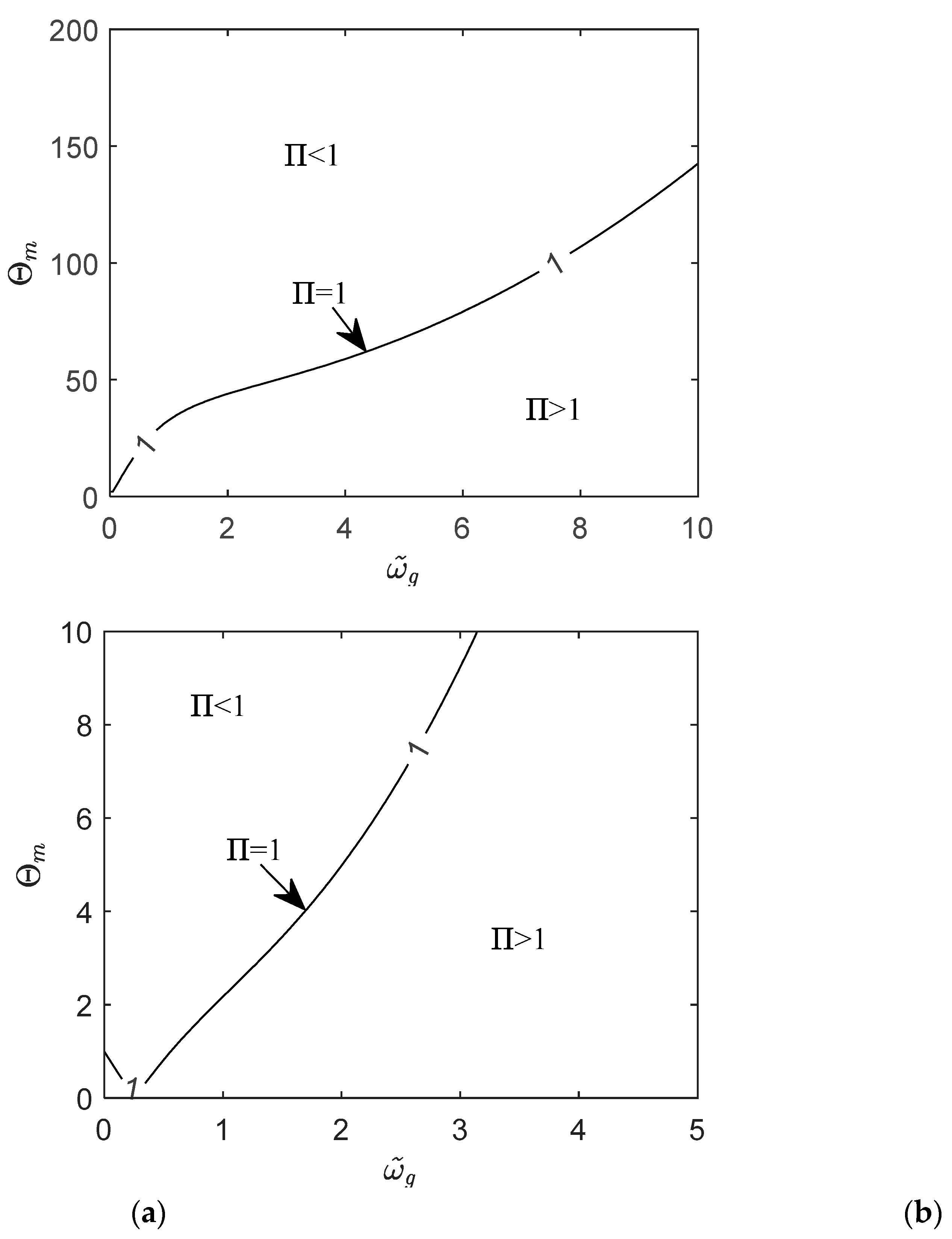
Figure 7.
Phase trajectory of the unified model with γ= 44.76, σ=44.68, Θm=128.7, Γm=11.3, and θ0=θ0(2)=3.25.
Figure 7.
Phase trajectory of the unified model with γ= 44.76, σ=44.68, Θm=128.7, Γm=11.3, and θ0=θ0(2)=3.25.
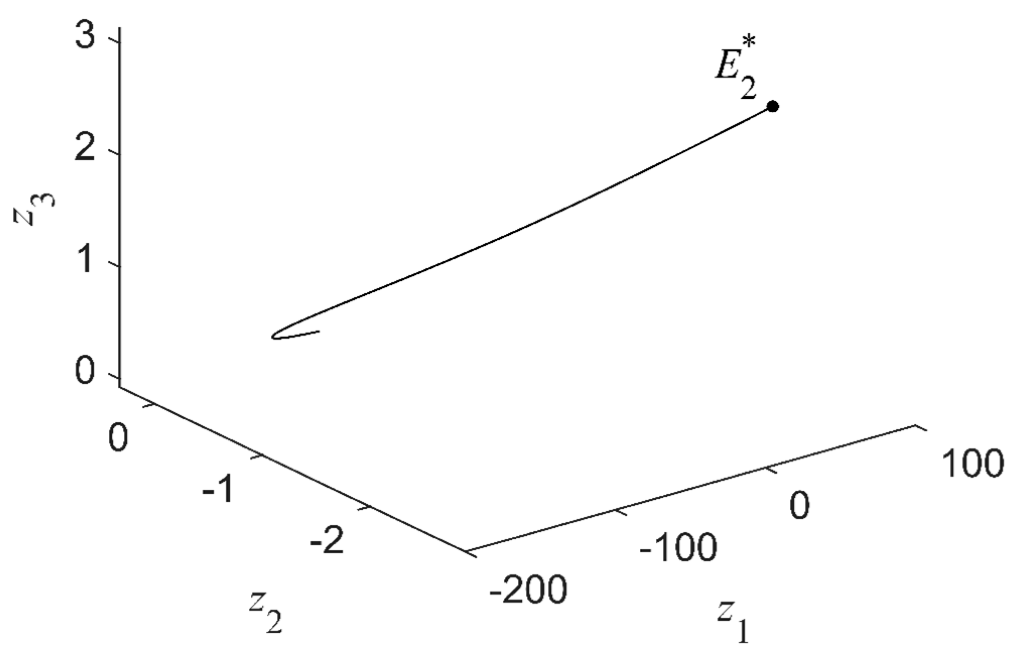
Figure 8.
Waveforms of the grid-connected unified model with γ= 44.76, σ=44.68, Θm=128.7, Γm=11.3, and θ0=θ0(2)=3.25.
Figure 8.
Waveforms of the grid-connected unified model with γ= 44.76, σ=44.68, Θm=128.7, Γm=11.3, and θ0=θ0(2)=3.25.
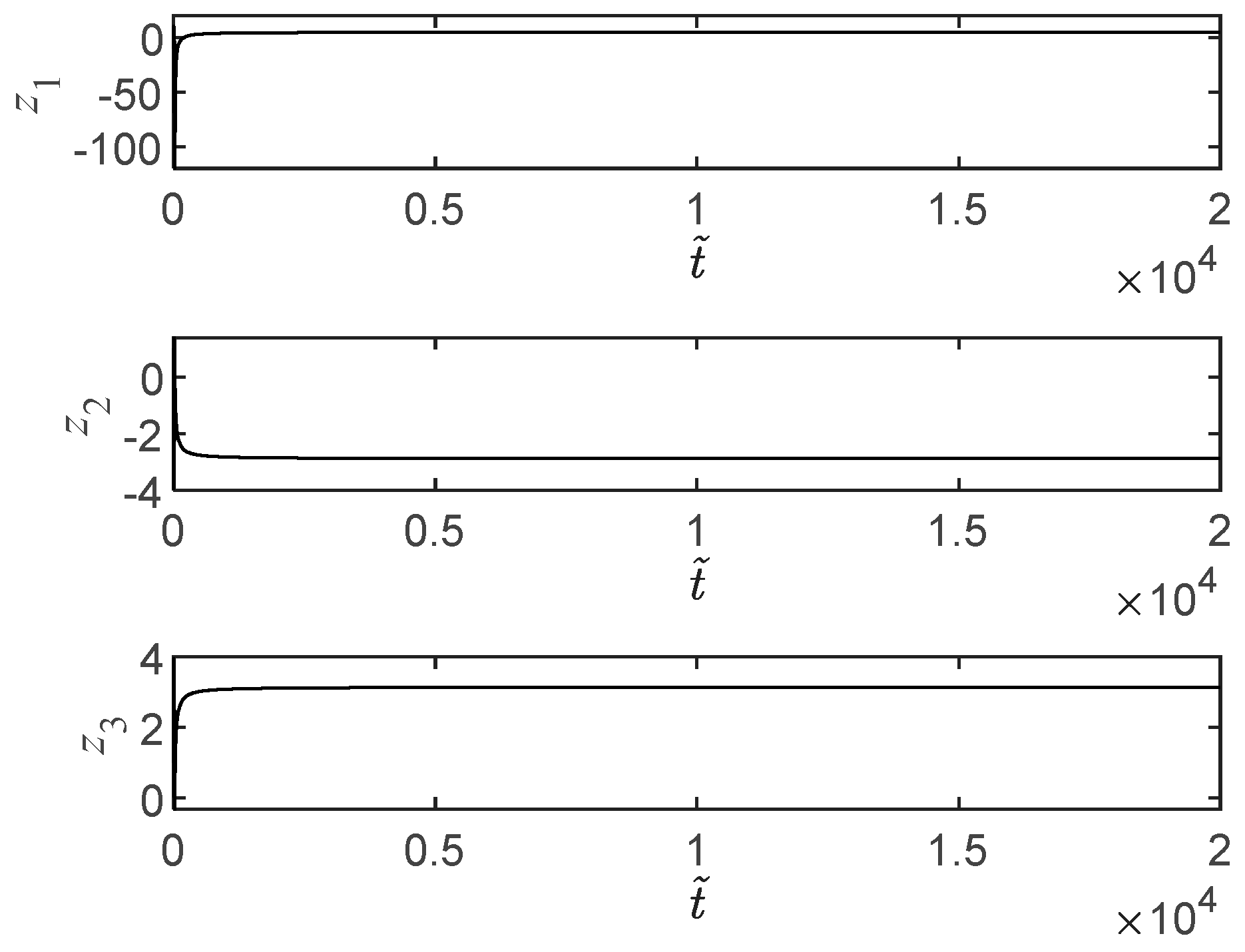
Figure 9.
Waveforms of the unified model: (a) VPMSG with Is=6A, np=8.85, ψr=0.4Wb, vd=2.79V and vq=162.6V. (b) VPCSG with , np=0.3, , and .
Figure 9.
Waveforms of the unified model: (a) VPMSG with Is=6A, np=8.85, ψr=0.4Wb, vd=2.79V and vq=162.6V. (b) VPCSG with , np=0.3, , and .
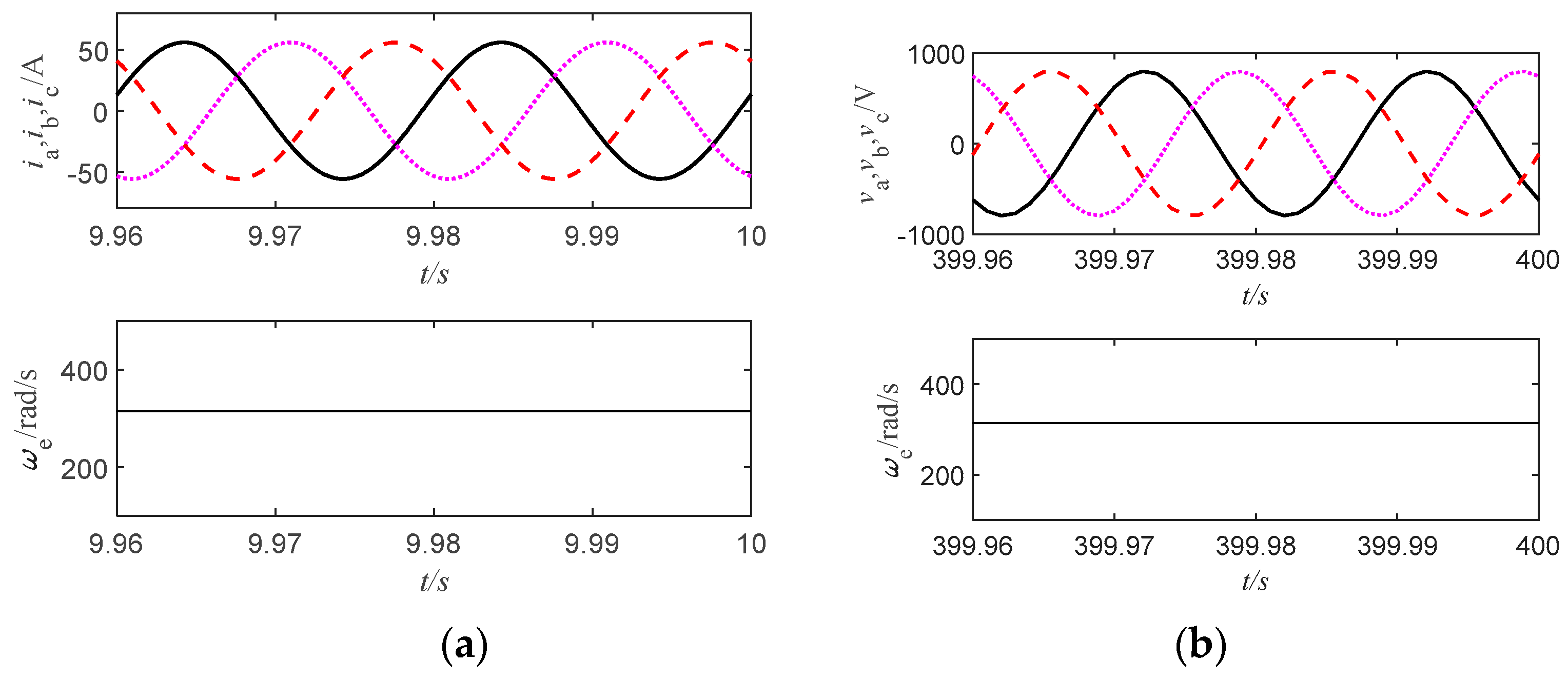
Figure 10.
Curves of the real parts of the rightmost eigenvalues: (a) VPMSG. (b) VPCSG.
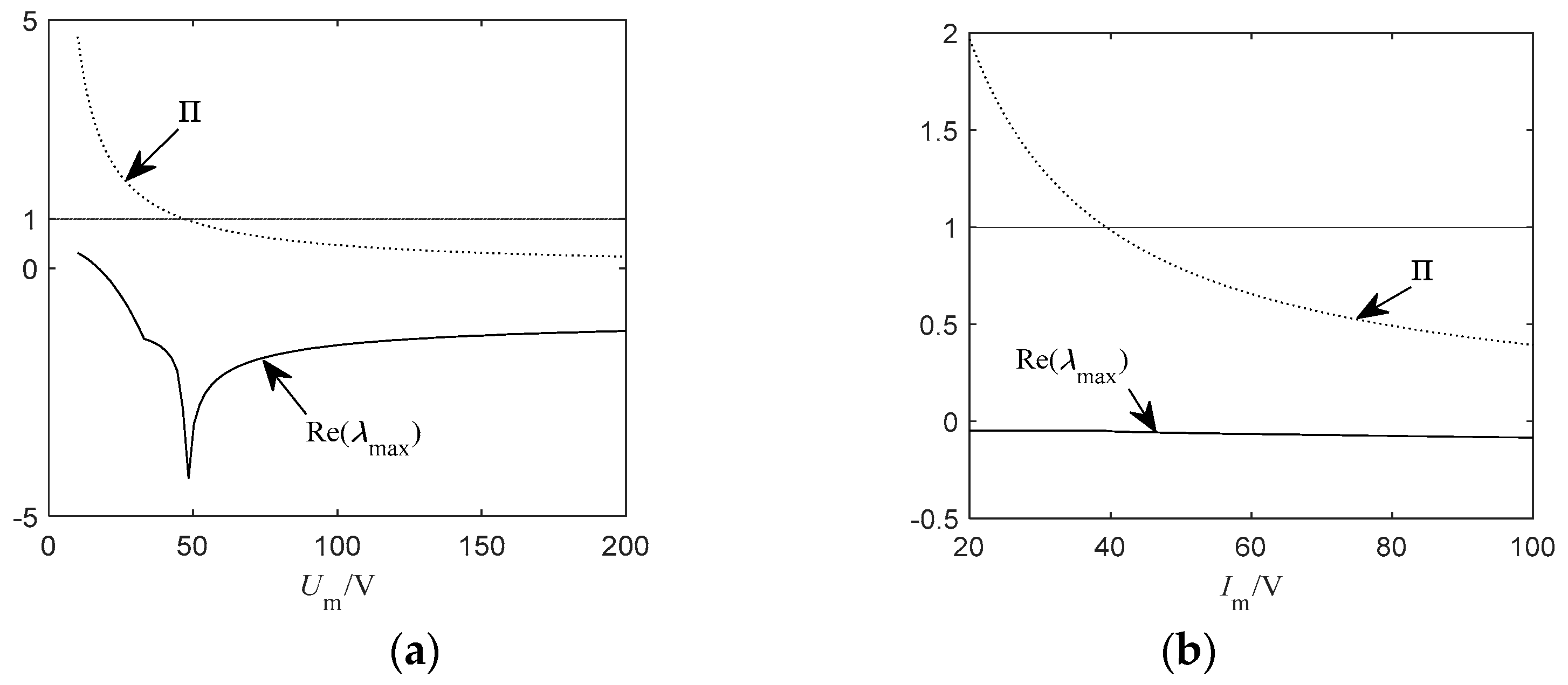
Figure 11.
Waveforms of the unified model: (a) VPMSG with Is=6A, np=8.85, ψr=0.4Wb, Um=115V, fg=50Hz and θ0=θ0(2)=3.25. (b) VPCSG with , np=0.5, , Im=42A, fg=50Hz and θ0=θ0(2)=3.35.
Figure 11.
Waveforms of the unified model: (a) VPMSG with Is=6A, np=8.85, ψr=0.4Wb, Um=115V, fg=50Hz and θ0=θ0(2)=3.25. (b) VPCSG with , np=0.5, , Im=42A, fg=50Hz and θ0=θ0(2)=3.35.
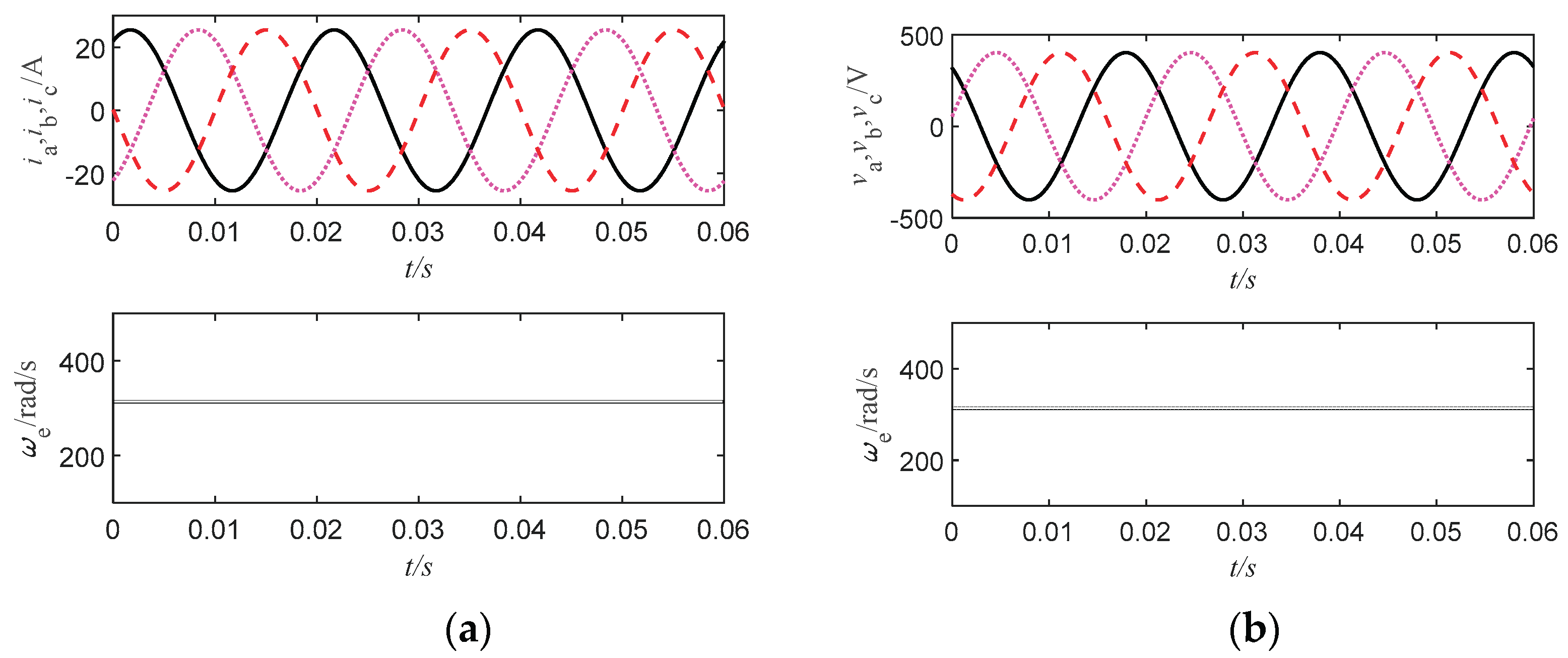

Table 1.
Dual terms between Equations (1) and (5).
| Equation (1) | Equation (5) | ||
| Description | Symbol | Description | Symbol |
| Voltage | Current | ||
| Current | Voltage | ||
| Flux | Charge | ||
| Resistance | Conductance | ||
Table 2.
Duality between VPMSG and VPCSG.
| VPMSG | VPCSG | ||
| Description | Expression | Description | Expression |
| Voltage Equations | Current Equations | ||
| Swing Equation | Swing Equation | ||
| Flux Equations | Charge Equations | ||
| Torque | Torque | ||
| Electrical Angular Frequency | ωe=npωm | Electrical Angular Frequency | |
| Electrical angle | θe | Electrical angle | |
Table 3.
Comparisons of VPMSG and VPCSG.
| Name | VPMSG | VPCSG |
| Swing Equations | ||
| Energy Storage Elements | Dc-link capacitor C | Dc-link inductor |
| Electrical Angular Frequency | ωe=npvdc | |
| Virtual Input Torque | Current source Is | Voltage source |
| Virtual Electromagnetic Torque |
Disclaimer/Publisher’s Note: The statements, opinions and data contained in all publications are solely those of the individual author(s) and contributor(s) and not of MDPI and/or the editor(s). MDPI and/or the editor(s) disclaim responsibility for any injury to people or property resulting from any ideas, methods, instructions or products referred to in the content. |
© 2026 by the authors. Licensee MDPI, Basel, Switzerland. This article is an open access article distributed under the terms and conditions of the Creative Commons Attribution (CC BY) license (http://creativecommons.org/licenses/by/4.0/).
Copyright: This open access article is published under a Creative Commons CC BY 4.0 license, which permit the free download, distribution, and reuse, provided that the author and preprint are cited in any reuse.