

Submitted:
25 August 2026
Posted:
26 August 2026
You are already at the latest version
Abstract
Locally resonant seismic metasurfaces can attenuate surface waves at sub-wavelength scales; however, fixed configurations are unable to adapt to varying site-specific frequency spectra. This paper proposes a mass-tunable spring-mass metasurface that achieves in-situ bandgap reconfiguration by altering the resonator mass. Combining three-dimensional Bloch simulations with full-scale sand-site experiments (7 × 6 array), the bandgap evolution within the 2–6 kg mass range is systematically investigated. Simulations demonstrate that increasing mass shifts all bandgaps toward lower frequencies, and when the mass reaches ≥3 kg, the decoupling of higher-order modes gives rise to a fourth bandgap, BG4. Experiments confirm this trend and further reveal the modal selectivity of bandgaps: BG2 and BG3 are effective for both Love and Rayleigh waves, whereas BG4 can only be excited by Rayleigh waves. Due to finite periodicity and damping effects, the low-frequency BG1 is difficult to observe experimentally. Overall, the resonator mass serves as a reversible and low-cost tuning degree of freedom, providing an engineering-feasible pathway for adaptive metasurface design.
Keywords:
seismic metamaterials
; elastic waves
; band-gap tuning
; energy attenuation
; local resonance
1. Introduction
Seismic surface waves are a major cause of damage to surface structures and infrastructure. Effective attenuation of these waves remains a critical challenge in geotechnical engineering and vibration protection. Locally resonant seismic metamaterials, leveraging sub-wavelength bandgap characteristics, can suppress elastic surface wave propagation at scales far smaller than the wavelength, overcoming the size limitations of conventional barriers and offering a novel paradigm for seismic vibration protection.
Since the introduction of the locally resonant phononic crystal concept, the manipulation of elastic waves by artificial periodic resonant media has been extensively studied, with theories extending from condensed matter physics and acoustics to interdisciplinary fields such as civil engineering and geophysics [1]. Liu et al. [2] demonstrated that resonant units can generate sub-wavelength bandgaps, with the physical essence equivalent to frequency-dependent negative effective mass density [3], a property that aligns well with the engineering demand for low-frequency seismic wave protection, leading to numerous investigations into discrete mass-spring units and composite metastructures [4].
Extending the resonant metamaterial concept to the field scale, a series of theoretical and experimental studies on seismic metasurfaces have emerged. Brûlé et al. [5] confirmed through field experiments that structured soil can reshape seismic surface wave fields. Colombi et al. [6] found that natural forests can act as seismic metamaterials, forming Rayleigh wave bandgaps via tree-based local resonances, and further proposed resonant metawedges for Rayleigh-to-body wave conversion [7]. Subsequent developments include embedded metabarriers [8], broadband seismic metastructures [9], large-scale seismic metamaterials [10], inertial resonator arrays [11], and isochronous mechanical oscillators [12], significantly enriching the design landscape of seismic metamaterials. Theoretically, researchers have established dispersion theories for surface resonator–Rayleigh wave interactions [13], extended the description of metasurface control over anti-plane Love waves [14], and incorporated Biot’s poroelastic theory to capture fluid-solid coupling effects in saturated foundations [15], completing the theoretical framework for half-space foundation–surface resonator coupling [16]. Meanwhile, multi-layered composites, multi-mass units, periodic foundations, and tank protection schemes have been thoroughly investigated [17,18,19,20,21,22,23]. Recently, nonlinear mechanisms have also been introduced to achieve amplitude-dependent dispersion and harmonic responses [24].
Despite the demonstrated potential of seismic metamaterials for surface wave suppression, insufficient bandgap tunability remains a core bottleneck hindering their transition from theoretical demonstration to practical engineering applications. Site conditions vary significantly in terms of soil stratification, and the dominant frequencies of seismic surface waves are strongly site-dependent; a metamaterial optimized for one site may suffer from substantially degraded performance when deployed elsewhere. Reported tuning strategies include modifying boundary constraints for ultra-low-frequency stop bands [25], spatially grading resonator heights to reshape dispersion topography [26], point-by-point refractive index modulation for metalens realization [27], and utilizing nonlinear stiffness for amplitude-dependent bandgap shifting [28]. Numerical simulations have explored the feasibility of mass-in-mass periodic barriers for strong ground motion attenuation [29]. Compared with these approaches, altering the resonator mass offers distinct advantages: conceptual simplicity, high engineering feasibility, and in-situ reversible reconfigurability—merely by adding or removing counterweights, the natural resonance frequency can be continuously tuned, enabling bandgap reconfiguration with promising engineering prospects.
At the same time, experimental validation in this direction remains notably insufficient. Most studies are confined to small-scale laboratory model tests [30,31,32]; the few field-scale experiments are largely based on natural resonant units such as trees [33] or employ fixed-parameter, non-in-situ-tunable embedded rigid structures [5,8]. To the best of our knowledge, full-scale field experiments on artificial spring-mass seismic metasurfaces deployed on real granular soil sites with in-situ tunable counterweights, incorporating quantitative decomposition of Love and Rayleigh wave attenuation and cross-validated with multi-parameter numerical simulations, remain scarce in the literature.
To address this gap, this paper employs the resonator mass as the tuning variable and systematically investigates its tuning effect on multi-order locally resonant bandgaps. Three-dimensional Bloch eigenmode simulations are first conducted over the 2–6 kg mass range to elucidate the physical mechanisms by which mass variation drives bandgap low-frequency shifting and higher-order mode decoupling that generates new bandgaps. Subsequently, a full-scale sweeping-frequency experiment is carried out on an 8.0 m × 2.0 m × 1.0 m sand foundation with a 7 × 6 resonator array, enabling quantitative analysis of total energy as well as decomposed Love and Rayleigh wave attenuation, with simulation predictions cross-validated against measured results. Following the paradigm of “parametric simulation scanning + extreme-mass field validation,” this study demonstrates the effectiveness of resonator mass as a bandgap tuning degree of freedom, providing theoretical and experimental support for site-adaptive seismic metasurface design.
2. Theoretical
2.1. Wave Equation and Bloch Eigenmode Analysis
The propagation of elastic waves in three-dimensional structures satisfies the Lamé equations [34,35]:
where E is Young’s modulus, ν is Poisson’s ratio, ρ is the medium density, u is the displacement field, and F is the body force, which is often neglected in bulk and surface wave calculations.
In a periodic potential field, the solution for elastic wave propagation can be expressed as [1,13]:
where r is the spatial coordinate vector, k is the Bloch wave vector, and ω is the angular frequency. The amplitude uk(r) can be written as a periodic function:
where a is the lattice vector. From Equation (2), the Bloch periodic boundary condition is obtained:
Substituting this into the Lamé equations (1), yields the eigenvalue equation:
where D(k) is the stiffness matrix, M is the mass matrix, and k is the wave vector. Based on this formulation, finite element simulations are conducted using COMSOL Multiphysics. The dispersion relations ω(k) are computed along the irreducible Brillouin zone path M–Γ–X–M for different structural configurations.
2.2. Equivalent Spring–Oscillator Model and Mass-Tuning Principle
According to the literature, each unit cell of a surface-resonator-type seismic metamaterial can be simplified as a spring-mass model [2,36], as shown in Figure 1.
The natural frequency is given by:
where f is the natural frequency, k is the spring stiffness, and m is the resonator mass. The periodically arranged metamaterial excites local resonance through harmonic vibration at the surface; the out-of-phase coupling between the resonators and the substrate generates negative effective dynamic parameters [2,36,37], thereby dissipating seismic wave energy and forming bandgaps. Thus, altering the surface mass enables tuning of the natural frequency and active bandgap control.
Figure 2 shows the plan view (a), cross-sectional view (b), and schematic of the spring–oscillator unit (c) of the designed structure. The spring is a standard manganese-steel die spring with a height of 50 mm, an outer diameter of 40 mm, an inner diameter of about 20 mm, and a maximum compression of 40%. The base is a poplar plate of 60 mm × 60 mm × 10 mm. The oscillator is a cylindrical PET cup with a diameter of 100 mm, a height of 200 mm, and a wall thickness of 2 mm. The detailed design parameters are listed in Table 1 and Table 2. The spring is rigidly connected to the PET cup and to the poplar base plate by bolts. The ballast mass (2, 3, 4, 5, and 6 kg) is the only tuning variable in this work: 2 kg and 6 kg are realized by filling the cup to a height of 0.20 m with river sand and iron sand, respectively, while 3–5 kg are realized by mixing river sand and iron sand at different ratios.
2.3. Unit-Cell Design and Material Parameters
2.4. Numerical Simulation Results and Analysis
This section presents two types of results: the detailed mode shapes and band structures of two representative masses (2 kg and 6 kg) that correspond directly to the experimental configurations (Section 2.4.1), and a summary of the band-gap boundaries covering the full parameter space from 2 to 6 kg (Section 2.4.2, Table 3).
2.4.1. Mode Shapes and Bandgaps for Representative Configurations: 2 kg and 6 kg
Based on the above parameters, the band diagrams of the oscillator filled with 2 kg of river sand and 6 kg of iron sand were simulated, as shown in Figure 3 and Figure 4, respectively.
As shown in Figure 3, the 2 kg resonator exhibits four vibrational modes: fx= 8.8 Hz (horizontal), fm = 48.3 Hz (mixed), fr1 = 75.1 Hz (torsional), and fr2 = 109.6 Hz (torsional). However, only the latter three open BG1, BG2, and BG3, respectively; the horizontal mode lies within the low-frequency passband and does not form an independent bandgap. The underlying physical mechanism is that the locally resonant unit is not an ideal point mass; beyond the fundamental translational mode, it possesses higher-order eigenmodes such as rocking and torsion [36,40]. Each higher-order mode corresponds to a higher natural frequency. When the incident wave frequency matches a higher-order modal frequency, out-of-phase coupling occurs between the resonator and the substrate, driving the effective dynamic parameters toward negative values [2,41]; elastic traveling waves can no longer propagate within that frequency range, and the bandgaps are thus sequentially formed.
Within the passband intervals between bandgaps, no strong out-of-phase coupling occurs for any resonance mode, and the periodic structure resumes supporting elastic wave propagation. Compared with BG1, the higher-order bandgaps BG2 and BG3 are generally narrower in bandwidth, and their frequency positions are primarily governed by the resonator geometry and support layout, with relatively limited influence from the lattice constant. Therefore, by tailoring the resonator parameters to excite multi-order resonances, this metamaterial can achieve multi-band elastic wave suppression.
As shown in Figure 4, the 6 kg resonator exhibits five vibrational modes: fx = 7.7 Hz (horizontal), fm = 35.8 Hz (mixed), fr1 = 66.9 Hz (torsional), fr2 = 87.2 Hz (torsional), and fr3 = 103.7 Hz (torsional), which form four complete bandgaps.
Comparing Figure 3 and Figure 4, the 2 kg case (river sand) yields three complete bandgaps (BG1, BG2, BG3), while the 6 kg case (iron sand) yields four (BG1, BG2, BG3, BG4). Along the high-symmetry path M–Γ–X–M, all bandgaps shift toward lower frequencies, consistent with the reduction in resonance frequencies predicted by Equation (6). Notably, the upper boundary of BG1 (fundamental translational bandgap) decreases from approximately 47.5 Hz to approximately 35.7 Hz, further enhancing low-frequency suppression capability—the most valuable change for seismic locally resonant metamaterials. BG2 and BG3 shift downward as well, and a fourth bandgap, BG4, emerges.
When the resonator mass is increased from 2 kg to 6 kg while the substrate and support stiffness remain unchanged, the low-frequency acoustic branch modes remain almost unaltered, as they correspond to the collective motion of the entire unit cell and are primarily governed by the substrate medium parameters. In contrast, the optically-like branches dominated by local resonance shift toward lower frequencies, causing BG1, BG2, and BG3 to move downward and improving low-frequency elastic wave suppression. As the mass further increases, the frequency spacing between higher-order resonance modes enlarges, the modes decouple, and the originally closely spaced higher-order bands separate, giving rise to the fourth complete bandgap BG4 and enabling suppression over additional frequency bands. Increasing the resonator mass can reduce the resonance frequencies but also increases the structural self-weight; practical engineering applications require a trade-off between low-frequency performance and structural weight.
2.4.2. Full Parameter Sweep (2–6 kg): Bandgap Migration and BG4 Emergence
Therefore, with other parameters held constant, the bandgaps for resonator masses ranging from 2 to 6 kg (achieved by different river sand/iron sand ratios) were computed via simulation, with results summarized in Table 3.
The numerical results demonstrate that increasing the resonator mass shifts all bandgaps toward lower frequencies, which is beneficial for low-frequency seismic wave control; however, the bandwidth of the first bandgap narrows accordingly. When the mass reaches 3 kg or above, higher-order locally resonant modes are excited, generating the fourth bandgap and further extending the vibration suppression frequency coverage. The responses of different bandgap orders to mass variation differ significantly; simply increasing the resonator mass cannot simultaneously optimize the low-frequency onset and broadband performance across all orders. Therefore, practical engineering design must comprehensively consider the onset frequency, bandwidth, and bandgap order to rationally optimize the resonator mass.
3. Experimental
3.1. Experimental Design
A full-scale field experiment was conducted using river sand with a particle size of 1–3 mm, piled into a sand bed of approximately 8.0 m × 2.0 m × 1.0 m (length × width × height). A 7 × 6 array of resonators was arranged on the sand bed according to the unit cell configuration shown in Figure 2. The ambient temperature during the experiment ranged from 20 to 25 °C, and the site remained dry.
Figure 5.
Photographs of the experimental site: (a) site overview, (b) vibration source, (c) sensors.
Figure 5.
Photographs of the experimental site: (a) site overview, (b) vibration source, (c) sensors.
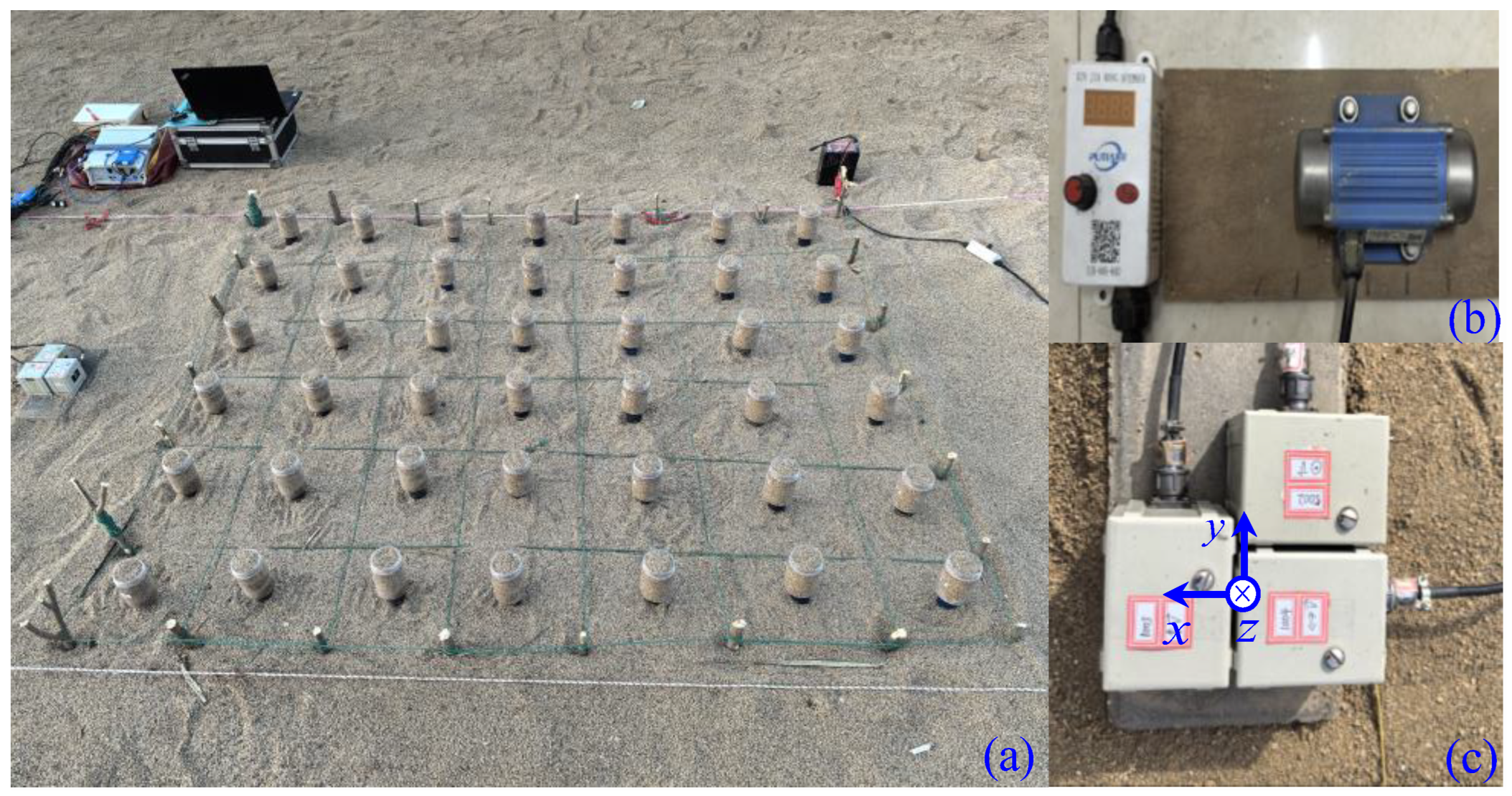
A variable-speed eccentric rotating mass shaker was used as the vibration source, with a maximum excitation force of 1 kN and continuously tunable frequency from 20 to 130 Hz. The shaker was buried approximately 50 cm deep in the sand bed—equivalent to a buried harmonic source in the Lamb problem sense [42]. Considering that excitation energy at very low frequencies would be indistinguishable from background noise, the frequency was swept from 21 Hz to 123 Hz at 3 Hz intervals, with a frequency error of approximately ±0.5 Hz. As defined in Figure 2, the horizontal axial direction is denoted as the x-direction, the horizontal transverse direction as the y-direction, and the vertical direction as the z-direction. A three-component sensor (bandwidth 0.5–150 Hz, low-frequency cut-off −3 dB) was placed 0.5 m from the array center at the front-facing position to record data. The sensors and the 24-bit data acquisition system were powered by 12 V and 24 V DC batteries, respectively. The resonators were designed with detachable containers for rapid mass replacement.
3.2. Data Processing
The experimental procedure consisted of: (1) measuring background energy, (2) measuring the energy under no-structure conditions at different excitation frequencies, and (3) measuring the energy distribution with the surface resonators installed. The excitation frequency of the eccentric shaker was adjusted; considering the nonlinear effects among sand particles, data were considered valid only when the dominant frequency recorded by the sensor matched the shaker frequency. The average energy per unit time was calculated by numerical integration, and energy exceeding five times the background level was regarded as effective.
The recording duration was set to 120 s, with the stable middle interval from t1 = 40 s to t2 = 80 s selected for analysis. The average energy per unit time in each direction was calculated as:
where mi is the sensor mass and vi is the instantaneous velocity recorded in each direction. The energy attenuation characteristics were then computed by comparing the energy at different frequency components at the same measurement point. The energy without surface resonators (no-structure condition) is denoted as E0, and the energy with resonators as Es, with corresponding components E0i and Esi (i=x,y,z).
The total energy attenuation coefficient ks and component energy attenuation coefficients ksi are defined as:
Considering that Love waves result from the superposition of horizontally polarized shear waves (SH) after multiple reflections from resonators, they are contained in the y-direction measurements [43,44]; Rayleigh waves result from the superposition of horizontal progressive waves (P) and vertical shear waves (SV) through the resonators, and are thus contained in the sum of x- and z-direction measurements [42,45,46]. The Love and Rayleigh wave attenuation coefficients, kL and kR, are accordingly defined as:
4. Results and Discussion
4.1. Total Energy Attenuation
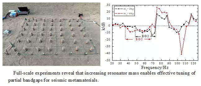
Figure 6 presents the total energy attenuation. The BG2 bandgap for the 2 kg resonator spans 48–73 Hz, while that for the 6 kg resonator shifts to 35–67 Hz, lowering the lower bound by 13 Hz and the upper bound by 6 Hz, in good agreement with simulation trends. In the high-frequency regime, the 2 kg case shows an attenuation interval of 90–106 Hz (falling within the simulated BG3 high-frequency portion, with the 75.8–90 Hz sub-band masked by sand damping and finite-period scattering), whereas the 6 kg case exhibits 93–113 Hz, which shifts upward relative to the simulated BG4 (88.8–103.1 Hz). This apparent contradiction to the expected mass-induced downward bandgap shift originates from the sensitivity of the high-order torsional/rocking modes (BG3, BG4) to the baseplate–sand contact stiffness, which evolves with the oscillator mass. For BG2, dominated by the fundamental translational mode, the spring stiffness plays the primary role, so the experimental low-frequency migration matches simulations well. Moreover, the 7 × 6 finite array cannot form a complete Bloch bandgap; the measured attenuation is a superposition of resonance, scattering, and soil damping, so quantitative deviations from ideal predictions are inherent.
4.2. Surface Wave Energy Attenuation
Love and Rayleigh wave attenuations were decomposed using Equation (10), as shown in Figure 7. For Love waves (Figure 7a), BG2 of the 2 kg resonator is 39–60 Hz; increasing mass to 6 kg lowers the lower bound to 36 Hz while the upper bound remains ~60 Hz, broadening the bandwidth by 3 Hz. An ultra-broadband attenuation band (60–118 Hz for 2 kg, 60–121 Hz for 6 kg) is observed, indicating excellent Love-wave suppression. For Rayleigh waves (Figure 7b), BG2 shifts from 35–73 Hz (2 kg) to 28–67 Hz (6 kg), lowering both bounds by 7 and 6 Hz, respectively, with bandwidth largely unchanged, consistent with simulations. In the high-frequency Rayleigh band, the 2 kg and 6 kg cases show 90–106 Hz and 93–113 Hz intervals, respectively. The out-of-plane rocking/torsional mode (BG4) can only be excited by the vertical component of Rayleigh waves; Love waves cannot activate it, so high-frequency attenuation is primarily Rayleigh-wave contribution. The upward shift of the 6-kg high-frequency band relative to simulated BG4 further confirms that higher-order bandgaps (BG3, BG4) are far more sensitive to site contact conditions and array finiteness than BG2.
4.3. Modal Selectivity and Simulation–Experiment Correspondence
Love waves, dominated by horizontal shear, effectively excite BG2 and BG3 (rocking and shear-tilt modes), while BG4 (out-of-plane torsion) is exclusively triggered by Rayleigh waves that possess vertical vibration components. Thus, BG4 manifests only in the Rayleigh spectrum (e.g., near 105 Hz for 6 kg, corresponding to the simulated BG4 in Figure 4f). The total energy attenuation is a superposition of both contributions. Quantitative comparison is subject to differing assumptions: the equivalent stiffness of BG3/BG4 involves not only spring stiffness but also oscillator structural rigidity and baseplate–sand contact stiffness, whereas the single-degree-of-freedom spring-mass relation applies mainly to the fundamental mode. Mass increase alters soil contact, perturbing high-order resonance frequencies—the key reason for simulation-experiment trend discrepancies for BG3/BG4. BG2, dominated by rocking/tilting, is less affected and shows better consistency. The experimentally observed high-frequency attenuation is mainly attributed to Rayleigh waves, rather than a strict Bloch complete bandgap, and reflects the combined effects of finite periodicity, sand heterogeneity, and damping. Nevertheless, the core physical trends—mass-induced low-frequency shifting, BG4 emergence via mode decoupling, and modal selectivity—are consistently captured by both approaches, aligning with observations reported in [47].
5. Conclusions
This study combines Bloch simulations with full-scale field tests on a 7 × 6 mass-tunable spring-resonator array to investigate bandgap tuning for surface waves. Key findings are:
(1) Mass-driven low-frequency shift and BG4 emergence. Increasing resonator mass (2→6 kg) shifts all bandgaps toward lower frequencies. When the mass reaches ≥3 kg, higher-order modes decouple, generating a fourth bandgap (BG4) in simulations. Experimentally, BG2 shifts from 48–73 Hz to 35–67 Hz, confirming this trend.
(2) Modal selectivity. BG2 and BG3 respond to both Love and Rayleigh waves. BG4, corresponding to an out-of-plane torsional mode, can only be excited by Rayleigh waves (via their vertical component), not by Love waves. This polarization-dependent behavior implies that the additional attenuation band from BG4 is available only for Rayleigh-wave-dominated sites; Love-wave-dominated sites still rely primarily on BG2 and BG3.
(3) Limitations and engineering implications. Low-frequency BG1 is not observable in the field due to the 21 Hz excitation lower limit, finite array size, and soil damping. Higher-order bandgaps (BG3, BG4) are highly sensitive to baseplate–sand contact stiffness, causing deviations from ideal infinite-period simulations. Hence, directly applying simulation-predicted high-order bandgap frequencies in engineering practice is inadvisable; site-specific contact nonlinearities must be taken into account. The resonator-mass tuning approach offers a reversible, low-cost, and practically feasible strategy for in-situ bandgap reconfiguration tailored to site-specific spectra. Overall, mass tuning effectively enables bandgap adaptation, but deployment strategies must account for wave polarization and soil contact effects. This full-scale dataset provides a valuable experimental reference for designing tunable seismic metasurfaces under realistic soil conditions.
Supplementary Materials
Not applicable.
Author Contributions
Conceptualization, X.Z. and Q.S.; methodology, C.J. and X.Z.; software, X.Z.; validation, X.Z., and Q.S.; formal analysis, X.Z.; C.J.; investigation, Q.S. and C.J.; resources, Y.L. and Q.S.; data curation, X.Z.; writing—original draft preparation, X.Z. and Q.S.; writing—review and editing, X.Z. and Q.S.; visualization, C.J.; supervision, Y.L. and Q.S.; project administration, Y.L.; funding acquisition, Y.L. and Q.S. All authors have read and agreed to the published version of the manuscript.
Funding
This research was funded by the Spark Program of the China Earthquake Administration, grant number XH26050A, and National Natural Science Foundation of China, grant number 11974044.
Institutional Review Board Statement
Not applicable.
Informed Consent Statement
Not applicable.
Data Availability Statement
The data supporting the findings of this study are available from the corresponding author upon reasonable request.
Acknowledgments
The authors acknowledge the support from the Spark Program of the China Earthquake Administration, grant number XH26050A, and National Natural Science Foundation of China, grant number 11974044.
Conflicts of Interest
The authors declare no conflicts of interest.
References
- Hussein, M.I.; Leamy, M.J.; Ruzzene, M. Dynamics of phononic materials and structures: Historical origins, recent progress, and future outlook. Appl. Mech. Rev. 2014, 66, 040802. [Google Scholar] [CrossRef]
- Liu, Z.Y.; Zhang, X.X.; Mao, Y.W.; Zhu, Y.Y.; Yang, Z.Y.; Chan, C.T.; Sheng, P. Locally resonant sonic materials. Science 2000, 289, 1734–1736. [Google Scholar] [CrossRef] [PubMed]
- Huang, H.H.; Sun, C.T.; Huang, G.L. On the negative effective mass density in acoustic metamaterials. Int. J. Eng. Sci. 2009, 47, 610–617. [Google Scholar] [CrossRef]
- Matlack, K.H.; Bauhofer, A.; Krödel, S.; Palermo, A.; Daraio, C. Composite 3D-printed metastructures for low-frequency and broadband vibration absorption. Proc. Natl. Acad. Sci. USA 2016, 113, 8386–8390. [Google Scholar] [CrossRef] [PubMed]
- Brûlé, S.; Javelaud, E.H.; Enoch, S.; Guenneau, S. Experiments on seismic metamaterials: Molding surface waves. Phys. Rev. Lett. 2014, 112, 133901. [Google Scholar] [CrossRef] [PubMed]
- Colombi, A.; Roux, P.; Guenneau, S.; Gueguen, P.; Craster, R.V. Forests as a natural seismic metamaterial: Rayleigh wave bandgaps induced by local resonances. Sci. Rep. 2016, 6, 19238. [Google Scholar] [CrossRef] [PubMed]
- Colombi, A.; Colquitt, D.; Roux, P.; Guenneau, S.; Craster, R.V. A seismic metamaterial: The resonant metawedge. Sci. Rep. 2016, 6, 27717. [Google Scholar] [CrossRef] [PubMed]
- Palermo, A.; Krödel, S.; Marzani, A.; Daraio, C. Engineered metabarrier as shield from seismic surface waves. Sci. Rep. 2016, 6, 39356. [Google Scholar] [CrossRef] [PubMed]
- Krödel, S.; Thomé, N.; Daraio, C. Wide band-gap seismic metastructures. Extrem. Mech. Lett. 2015, 4, 111–117. [Google Scholar] [CrossRef]
- Miniaci, M.; Krushynska, A.; Bosia, F.; Pugno, N.M. Large scale mechanical metamaterials as seismic shields. New J. Phys. 2016, 18, 083041. [Google Scholar] [CrossRef]
- Achaoui, Y.; Ungureanu, B.; Enoch, S.; Brûlé, S.; Guenneau, S. Seismic waves damping with arrays of inertial resonators. Extrem. Mech. Lett. 2016, 8, 30–37. [Google Scholar] [CrossRef]
- Finocchio, G.; Casablanca, O.; Ricciardi, G.; Alibrandi, U.; Garescì, F.; Chiappini, M.; Azzerboni, B. Seismic metamaterials based on isochronous mechanical oscillators. Appl. Phys. Lett. 2014, 104, 191903. [Google Scholar] [CrossRef]
- Colquitt, D.J.; Colombi, A.; Craster, R.V.; Roux, P.; Guenneau, S.R.L. Seismic metasurfaces: Sub-wavelength resonators and Rayleigh wave interaction. J. Mech. Phys. Solids 2017, 99, 379–393. [Google Scholar] [CrossRef]
- Palermo, A.; Marzani, A. Control of Love waves by resonant metasurfaces. Sci. Rep. 2018, 8, 7234. [Google Scholar] [CrossRef] [PubMed]
- Pu, X.; Palermo, A.; Cheng, Z.; Shi, Z.; Marzani, A. Seismic metasurfaces on porous layered ground: Surface resonances and fluid-solid interaction effects on the propagation of Rayleigh waves. Int. J. Eng. Sci. 2020, 154, 103347. [Google Scholar] [CrossRef]
- Pu, X.; Palermo, A.; Marzani, A. Lamb’s problem for a half-space coupled to a generic distribution of oscillators at the surface. Int. J. Eng. Sci. 2021, 168, 103547. [Google Scholar] [CrossRef]
- Palermo, A.; Vitali, M.; Marzani, A. Metabarriers with multi-mass locally resonating units for broad band Rayleigh waves attenuation. Soil Dyn. Earthq. Eng. 2018, 113, 265–277. [Google Scholar] [CrossRef]
- Cheng, Z.; Shi, Z. Composite periodic foundation and its application for seismic isolation. Earthq. Eng. Struct. Dyn. 2018, 47, 925–944. [Google Scholar] [CrossRef]
- Basone, F.; Wenzel, M.; Bursi, O.S.; Fossetti, M. Finite locally resonant metafoundations for the seismic protection of fuel storage tanks. Earthq. Eng. Struct. Dyn. 2019, 48, 232–252. [Google Scholar] [CrossRef]
- Chen, Y.; Hu, T.; Guo, F.; Chen, X.; Hu, G. Harnessing multi-layered soil to design seismic metamaterials with ultralow frequency band gaps. Mater. Des. 2019, 175, 107813. [Google Scholar] [CrossRef]
- Zeng, Y.; Du, Q.J.; Xu, Y.; Wang, L.; Li, B.; Deng, P.; Assouar, B. A Matryoshka-like seismic metamaterial with wide band-gap characteristics. Int. J. Solids Struct. 2020, 185–186, 334–341. [Google Scholar] [CrossRef]
- Lim, C.W.; Reddy, J.N. Built-up structural steel sections as seismic metamaterials for surface wave attenuation with low frequency wide bandgap in layered soil medium. Eng. Struct. 2019, 188, 440–451. [Google Scholar] [CrossRef]
- Mu, D.; Shu, H.; Zhao, L.; An, S. A review of research on seismic metamaterials. Adv. Eng. Mater. 2020, 22, 1901148. [Google Scholar] [CrossRef]
- Lou, J.; Ma, J.; Zhang, X.; Huang, Y. Propagation of fundamental and third harmonics along a nonlinear seismic metasurface. Int. J. Mech. Sci. 2022, 221, 107189. [Google Scholar] [CrossRef]
- Achaoui, Y.; Antonakakis, T.; Brûlé, S.; Craster, R.V.; Enoch, S.; Guenneau, S. Clamped seismic metamaterials: Ultra-low frequency stop bands. New J. Phys. 2017, 19, 063022. [Google Scholar] [CrossRef]
- Colombi, A.; Ageeva, V.; Smith, R.J.; Clare, A.; Patel, R.; Clark, M.; Colquitt, D.; Roux, P.; Guenneau, S.; Craster, R.V. Enhanced sensing and conversion of ultrasonic Rayleigh waves by elastic metasurfaces. Sci. Rep. 2017, 7, 6750. [Google Scholar] [CrossRef] [PubMed]
- Colombi, A. Resonant metalenses for flexural waves. J. Acoust. Soc. Am. 2016, 140, EL423–EL429. [Google Scholar] [CrossRef] [PubMed]
- Palermo, A.; Yousefzadeh, B.; Daraio, C.; Marzani, A. Rayleigh wave propagation in nonlinear metasurfaces. J. Sound Vib. 2022, 520, 116599. [Google Scholar] [CrossRef]
- Dertimanis, V.K.; Antoniadis, I.A.; Chatzi, E.N. Feasibility analysis on the attenuation of strong ground motions using finite periodic lattices of mass-in-mass barriers. J. Eng. Mech. 2016, 142, 04016060. [Google Scholar] [CrossRef]
- Palermo, A.; Krödel, S.; Matlack, K.H.; Daraio, C. Hybridization of guided surface acoustic modes in unconsolidated granular media by a resonant metasurface. Phys. Rev. Appl. 2018, 9, 054026. [Google Scholar] [CrossRef]
- Zaccherini, R.; Colombi, A.; Palermo, A.; Marzani, A. Locally resonant metasurfaces for shear waves in granular media. Phys. Rev. Appl. 2020, 13, 034055. [Google Scholar] [CrossRef]
- Cao, L.; Wan, Y.; Yang, Z.; Wang, Y.; Assouar, B. Disordered elastic metasurfaces. Phys. Rev. Appl. 2020, 13, 014054. [Google Scholar] [CrossRef]
- Lott, M.; Roux, P.; Garambois, S.; Guéguen, P.; Colombi, A. Evidence of metamaterial physics at the geophysics scale: The METAFORET experiment. Geophys. J. Int. 2020, 220, 1330–1339. [Google Scholar] [CrossRef]
- Graff, K.F. Wave Motion in Elastic Solids; Dover: New York, NY, USA, 1991. [Google Scholar]
- Achenbach, J.D. Wave Propagation in Elastic Solids; North-Holland: Amsterdam, The Netherlands, 1973. [Google Scholar]
- Boechler, N.; Eliason, J.K.; Kumar, A.; Maznev, A.A.; Nelson, K.A.; Fang, N. Interaction of a contact resonance of microspheres with surface acoustic waves. Phys. Rev. Lett. 2013, 111, 036103. [Google Scholar] [CrossRef] [PubMed]
- Maznev, A.A.; Gusev, V.E. Waveguiding by a locally resonant metasurface. Phys. Rev. B 2015, 92, 115422. [Google Scholar] [CrossRef]
- Garova, E.A.; Maradudin, A.A.; Mayer, A.P. Interaction of Rayleigh waves with randomly distributed oscillators on the surface. Phys. Rev. B 1999, 59, 13291–13296. [Google Scholar] [CrossRef]
- Khelif, A.; Achaoui, Y.; Benchabane, S.; Laude, V.; Aoubiza, B. Locally resonant surface acoustic wave band gaps in a two-dimensional phononic crystal of pillars on a surface. Phys. Rev. B 2010, 81, 214303. [Google Scholar] [CrossRef]
- Xiao, Y.; Wen, J.; Wen, X. Flexural wave band gaps in locally resonant thin plates with periodically attached spring-mass resonators. J. Phys. D. Appl. Phys. 2012, 45, 195401. [Google Scholar] [CrossRef]
- Rupin, M.; Lemoult, F.; Lerosey, G.; Roux, P. Experimental demonstration of ordered and disordered multiresonant metamaterials for Lamb waves. Phys. Rev. Lett. 2014, 112, 234301. [Google Scholar] [CrossRef] [PubMed]
- Lamb, H. On the propagation of tremors over the surface of an elastic solid. Philos. Trans. R. Soc. A 1904, 203, 1–42. [Google Scholar] [CrossRef]
- Love, A.E.H. Some Problems of Geodynamics; Cambridge University Press: Cambridge, UK, 1911. [Google Scholar]
- Pu, X.; Shi, Z. Broadband surface-wave attenuation in periodic trench barriers. J. Sound Vib. 2020, 468, 115130. [Google Scholar] [CrossRef]
- Zhang, X.C.; Zheng, N.; Ji, C.Y.; Lu, Y.L.; Shi, Q.F. Attenuation of seismic waves using resonant metasurfaces: A field study on an array of rubber oscillators. Mater. Today Commun. 2024, 41, 110659. [Google Scholar] [CrossRef]
- Zhang, X.C.; Zheng, N.; Ji, C.Y.; Lu, Y.L.; Shi, Q.F. First full-scale 2D field experiment on semi-embedded rubber column metamaterials: Enhanced attenuation of Love waves and mechanistic insights. Materials 2025, 18, 5517. [Google Scholar] [CrossRef] [PubMed]
- Achaoui, Y.; Khelif, A.; Benchabane, S.; Robert, L.; Laude, V. Experimental observation of locally-resonant and Bragg band gaps for surface guided waves in a phononic crystal of pillars. Phys. Rev. B 2011, 83, 104201. [Google Scholar] [CrossRef]
Figure 1.
Spring–oscillator model.
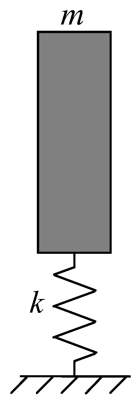
Figure 2.
Design schematics: (a) plan view, (b) cross-sectional view, (c) spring-resonator configuration.
Figure 2.
Design schematics: (a) plan view, (b) cross-sectional view, (c) spring-resonator configuration.
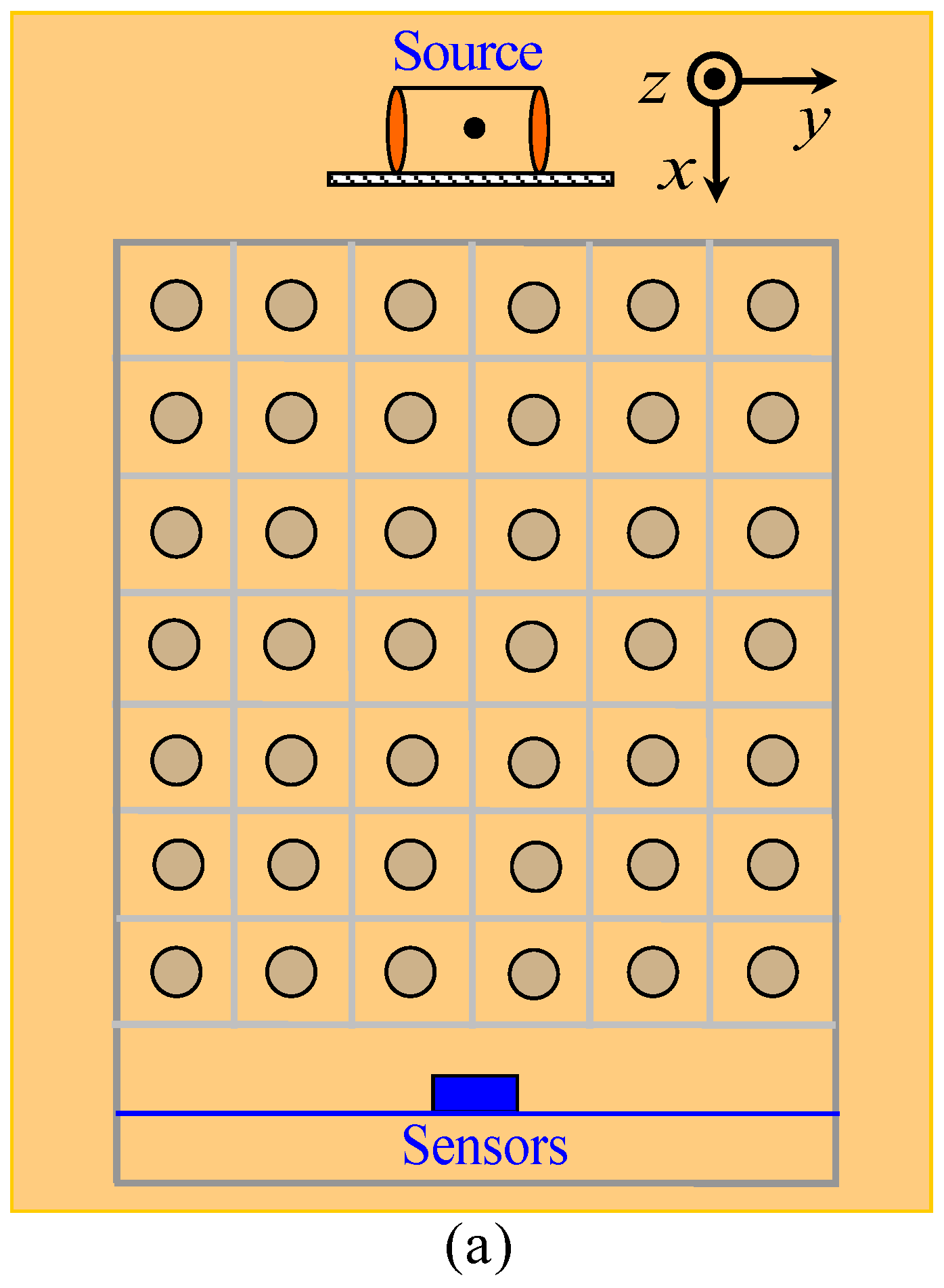
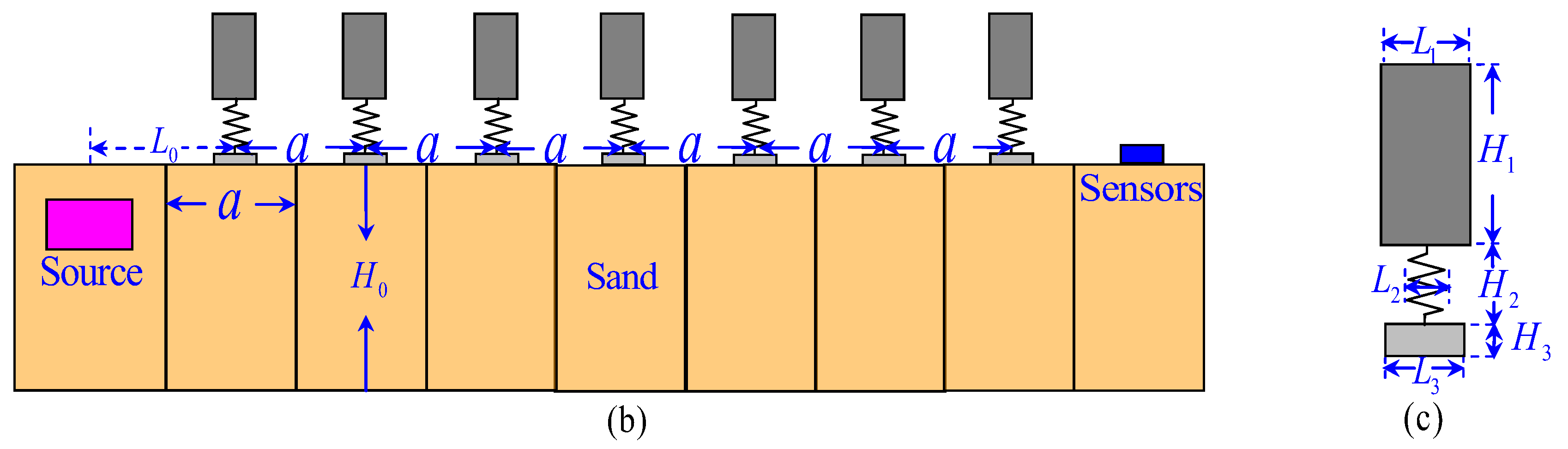
Figure 3.
Mode shapes and band diagram for the resonator filled with 0.20 m river sand (2 kg): (a) fx = 8.8Hz, (b) fm = 48.3Hz, (c) fr1 = 75.1Hz, (d) fr2 = 109.6Hz, (e) band diagram.
Figure 3.
Mode shapes and band diagram for the resonator filled with 0.20 m river sand (2 kg): (a) fx = 8.8Hz, (b) fm = 48.3Hz, (c) fr1 = 75.1Hz, (d) fr2 = 109.6Hz, (e) band diagram.
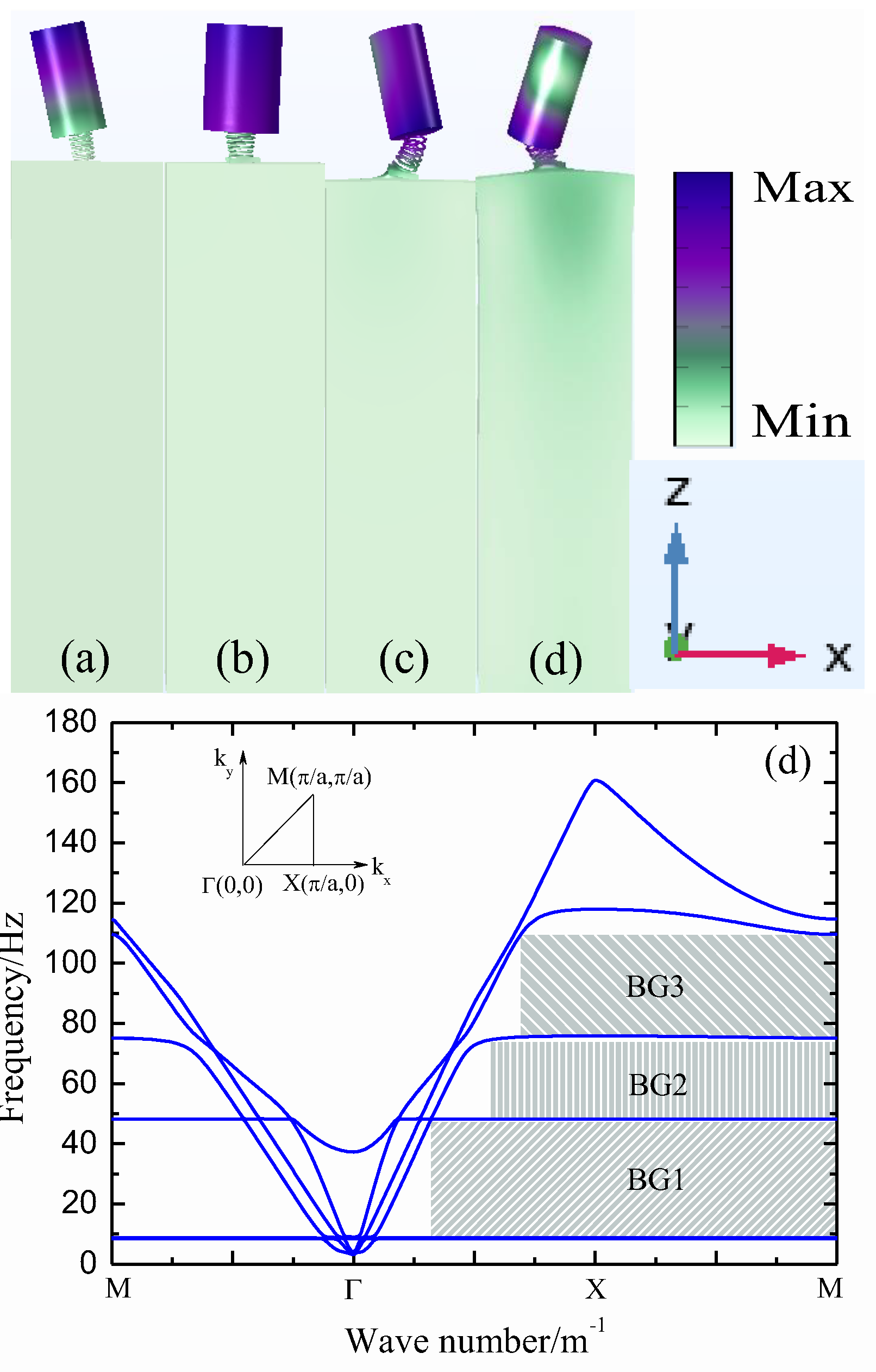
Figure 4.
Mode shapes and band diagram for the resonator filled with 0.20 m iron sand (6 kg): (a) fx = 7.7Hz, (b) fm = 35.8Hz, (c) fr1 = 66.9Hz, (d) fr2 = 87.2Hz, (e) fr3 =103.7Hz, (f) band diagram.
Figure 4.
Mode shapes and band diagram for the resonator filled with 0.20 m iron sand (6 kg): (a) fx = 7.7Hz, (b) fm = 35.8Hz, (c) fr1 = 66.9Hz, (d) fr2 = 87.2Hz, (e) fr3 =103.7Hz, (f) band diagram.
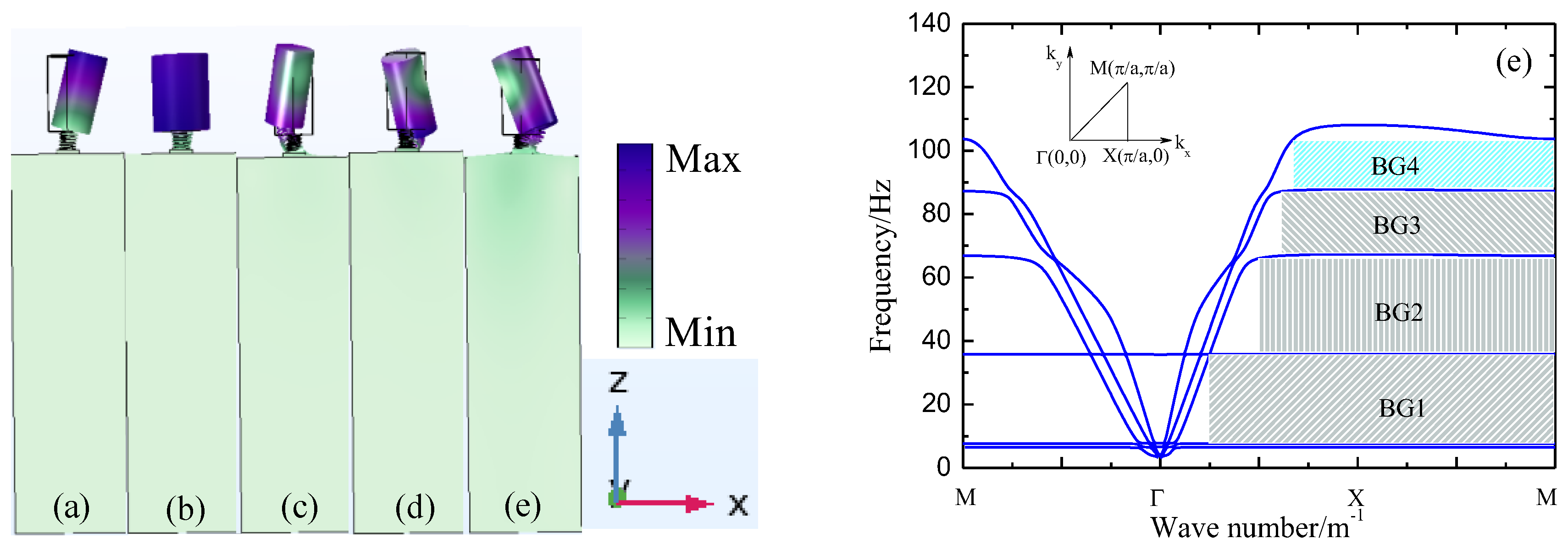
Figure 6.
Total energy attenuation.
Figure 7.
Energy attenuation for different wave types at the front-facing position: (a) Love waves, (b) Rayleigh waves.
Figure 7.
Energy attenuation for different wave types at the front-facing position: (a) Love waves, (b) Rayleigh waves.
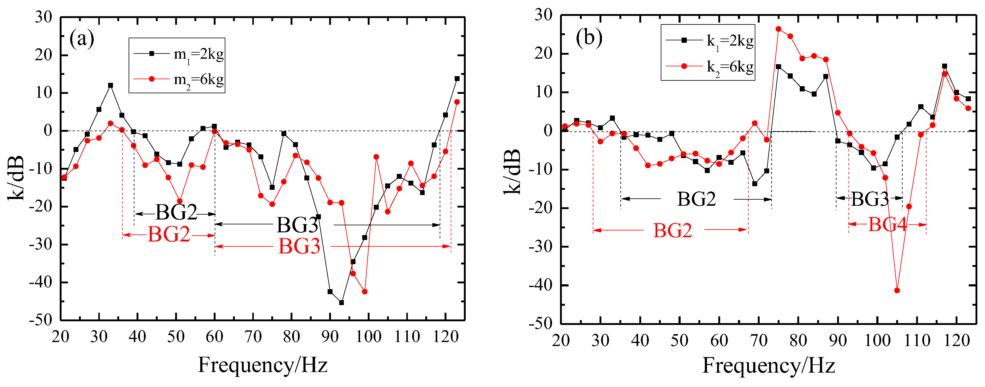

Table 1.
Design parameters.
| L0(m) | L1(m) | L2(m) | L3(m) | H0(m) | H1(m) | H2(m) | H3(m) |
| 0.3 | 0.1 | 0.04 | 0.06 | 1.0 | 0.20 | 0.05 | 0.01 |
Table 2.
Material parameters.
| Material | Density ρ (kg/m3) | Young’s Modulus E (MPa) | Poisson’s Ratio ν |
|---|---|---|---|
| River sand | 1400 | 20.0 | 0.47 |
| Poplar wood | 400 | 200 | 0.35 |
| PET | 1320 | 2.53×10³ | 0.35 |
| Iron sand | 4400 | 1.00×10⁵ | 0.31 |
| Manganese steel | 7850 | 2.05×10⁵ | 0.25 |
Table 3.
Bandgap variations with resonator mass.
| Mass m(kg) | BG1(Hz) | BG2(Hz) | BG3(Hz) | BG4(Hz) |
| 2 | 9.4-47.5 | 48.8-74.4 | 75.8-109.3 | — |
| 3 | 8.7-40.0 | 40.3-70.5 | 72.4-92.8 | 94.1-107.3 |
| 4 | 8.5-38.1 | 39.4-69.0 | 70.9-90.6 | 91.9-105.1 |
| 5 | 8.3-36.0 | 37.3-67.5 | 69.5-89.2 | 90.5-103.6 |
| 6 | 7.6-35.7 | 36.7-65.8 | 67.8-87.6 | 88.8-103.1 |
Disclaimer/Publisher’s Note: The statements, opinions and data contained in all publications are solely those of the individual author(s) and contributor(s) and not of MDPI and/or the editor(s). MDPI and/or the editor(s) disclaim responsibility for any injury to people or property resulting from any ideas, methods, instructions or products referred to in the content. |
© 2026 by the authors. Licensee MDPI, Basel, Switzerland. This article is an open access article distributed under the terms and conditions of the Creative Commons Attribution (CC BY) license (http://creativecommons.org/licenses/by/4.0/).
Copyright: This open access article is published under a Creative Commons CC BY 4.0 license, which permit the free download, distribution, and reuse, provided that the author and preprint are cited in any reuse.