

Submitted:
24 August 2026
Posted:
26 August 2026
You are already at the latest version
Abstract
The technological foundations for creating new composite materials based on solid emulsions of UV photopolymers are considered. Samples of photopolymer composites with artificial porosity, representing solid emulsions based on photopolymer resin and various liquids and colloidal solutions, have been obtained. The work develops methods for synthesis and formation of artificial porous structures, methods for controlling pore morphology, and approaches to filling pores with active liquid phases. Mechanisms for controlling the electrodynamic parameters of such materials are examined, as well as methods for their diagnostics in a wide frequency range. The electrophysical characteristics of the composites in the low-frequency and microwave ranges are investigated. It is shown that the features of the frequency dispersion of the dielectric parameters of the samples are influenced by the presence of a liquid phase in the pores of the composite. The obtained type of composite materials is promising for the development of next-generation acoustic and electrodynamic media with controllable parameters (acoustic impedance, dielectric susceptibility, polarizability, magnetization, attenuation for different types of acoustic and electromagnetic waves). The developed technologies may find practical application in the creation of new functional materials that can be effectively used in the fabrication of metamaterials with unique properties, tunable over a wide frequency range for radio engineering modules, as well as in adaptive electrodynamic and acoustic systems.
Keywords:
solid emulsions
; UV photopolymer composites
; artificial porosity
; filled pores
; metamaterials
; smart materials
1. Introduction
Modern materials science is increasingly turning to the concept of hybrid materials that combine the properties of solid and liquid components to achieve functional characteristics unattainable for homogeneous systems. One of the most promising approaches to creating such materials is the technology of “solid emulsions”, where composite materials are obtained by UV curing of photopolymerizable emulsions [1]. This method makes it possible to form a polymer matrix with finely dispersed inclusions of a liquid phase or, after its removal, to obtain a strictly controlled porous structure. Owing to the possibility of precise control of morphology and composition, solid emulsions based on UV photopolymers are becoming a platform for creating a new class of materials with programmable physical properties.
Of considerable interest are composite materials whose structure contains liquid or colloidal inclusions enclosed in a solid polymer matrix. Such systems, in essence, represent solid emulsions, allowing the combination of mechanical stability of a solid body with the possibility of reconfiguring electrodynamic properties by changing the composition, concentration, or external influence on the liquid phase. The emulsion templating method is one of the most effective approaches to creating highly porous polymer materials with controlled pore architecture [1,2,3]. At the same time, photopolymerization under ultraviolet (UV) radiation provides rapid curing of the liquid composition at room temperature, high spatial resolution, and compatibility with additive technologies, which makes UV photopolymers a particularly attractive matrix for creating next-generation functional materials [4].
A key feature of the approach under consideration is that the pores in the photopolymer matrix are not voids, but are filled with a liquid or colloidal dispersion with specified dielectric or magnetic properties. This architecture—“solid emulsion – liquid in pores”—fundamentally differs from traditional porous dielectrics, where pores usually remain filled with air and serve to reduce dielectric permittivity. In contrast, in the proposed system, the liquid content of the pores becomes an active component determining the effective electrodynamic characteristics of the composite. By varying the composition of the liquid (polarity, ionic strength, concentration of colloidal particles), one can widely adjust the complex dielectric permittivity, conductivity, and even magnetic properties of the material. Moreover, external influences—electric or magnetic field, temperature, UV irradiation—can induce reorientation or redistribution of the liquid phase and colloidal particles inside the pores, providing dynamic in situ tuning of electrodynamic parameters.
The current development of microwave techniques, telecommunication systems, radar, and metamaterials imposes ever-increasing demands on functional materials with controllable electrodynamic parameters [5]. The ability to actively or passively change dielectric permittivity, magnetic susceptibility, and conductivity over a wide frequency range opens prospects for creating tunable filters, phase shifters, antenna arrays, and devices with dynamically adjustable characteristics [6,7,8,9,10]. Traditional approaches to controlling electrodynamic parameters based on introducing conductive or ferroelectric fillers into a polymer matrix are often limited by a narrow adjustment range, irreversibility of changes, or technological complexity.
Materials based on UV-curable solid emulsions also open new opportunities in acoustic technologies [11,12]. Their main value lies in the possibility of precise control of the microstructure (pore size, shape, and connectivity), which directly affects the macroscopic acoustic properties, allowing the creation of devices with parameters unattainable for traditional materials.
2. Materials and Methods
2.1. Methods
The concept of “solid emulsions” is implemented by curing a photopolymer matrix containing dispersed droplets of an immiscible liquid. After curing, these droplets are either removed (e.g., by dissolution or evaporation), thereby creating a strictly controlled porosity, or they remain inside the material to obtain hybrid solid–liquid composites (SLC) with unique properties. The main challenge here is that the two phases tend to separate, and it is necessary that the photopolymer cures in such a way that the electrolyte droplets retain their shape.
A key advantage of this approach is emulsion templating, where the porous structure of the material is an exact replica (template) of the original emulsion droplets. This allows obtaining exceptionally high, up to 70–75%, interconnected porosity with controlled pore sizes ranging from a few to hundreds of micrometres [1]. The emulsion must be sufficiently viscous so that the droplets are “frozen” in the volume and cannot move and collide quickly.
The main approaches to obtaining such materials include combining classical emulsion templating with various UV-assisted techniques:
- Casting – the photopolymerizable emulsion is poured into a mould and then irradiated with UV light [13].
- Direct Ink Writing (DIW) 3D printing – paste-like emulsions with a high internal phase content, i.e., high-internal-phase emulsions (HIPEs), are used. Owing to shear thinning, they are easily extruded through a nozzle, but immediately after deposition they quickly recover high viscosity, allowing the creation of complex 3D objects with hierarchical porosity (e.g., woodpile structures for tissue engineering) [14].
- VAT photopolymerization – low-viscosity emulsions are used in digital light processing (DLP) and stereolithography (SLA) technologies. In this case, water microdroplets in the emulsion serve as “soft templates” for creating pores within the printed layer, enabling the fabrication of objects with tunable mechanical properties [15].
In any of these methods, the most important factor for success is emulsion stability. To create a robust barrier around electrolyte droplets, polyelectrolytes—charged polymers—are required. They adsorb at the phase interface, creating an electrostatic and steric barrier that physically prevents droplet coalescence [16]. The addition of high-molecular-weight polyelectrolytes itself increases viscosity. The higher the molecular weight of the polyelectrolyte, the thicker the protective layer and the more viscous the system becomes. In this case, a polyelectrolyte is needed that is soluble in the aqueous phase (electrolyte) but has hydrophobic segments that can be anchored in the photopolymer [17]. To increase viscosity, special thickeners compatible with the photopolymer can also be used.
Charged polyelectrolyte shells cause droplets to repel each other. The efficiency of this repulsion depends on the pH and ionic strength of the electrolyte solution. The more polyelectrolyte or surfactant molecules available, the faster they cover the droplet surface, preventing coalescence and allowing further breakup. There is an optimal concentration at which the droplet size is minimal. The use of diblock or triblock copolymers (with hydrophilic and hydrophobic blocks) allows precise “tuning” of droplet size. The hydrophobic block of the copolymer is anchored in the photopolymer, while the hydrophilic block retains the electrolyte droplet. Polyelectrolytes with high molecular weight form a thicker steric barrier, better stabilising small droplets and preventing their coalescence [18,19].
If the polyelectrolyte is more strongly charged, e.g., contains amino groups, it will work better in an acidic environment; if it contains sulfo groups, then in an alkaline one. By changing the pH of the electrolyte, one can vary the charge density on the droplet shell, hence the repulsive force, as well as the ability to maintain small size [20].
High salt content in the electrolyte screens (neutralises) the charges on the polyelectrolyte. This causes the polymer chain to “collapse”, the protective layer becomes thinner, and droplets can coalesce more easily. To obtain small droplets, the ionic strength should be optimal (not too high) [21].
Increasing the viscosity of the photopolymer hinders droplet movement and coalescence, thus preserving the fine-disperse structure. At high aqueous phase content, droplets are closer together and the risk of coalescence is higher, which usually requires more intensive stirring or more stabiliser to maintain small droplet size.
In addition to traditional surfactants, Pickering emulsions are widely used. In these, the role of stabiliser is played by solid micro- or nanoparticles (e.g., SiO₂), which irreversibly adsorb at the phase interface, with droplet size determined by the size and wettability of these particles. This imparts exceptional stability to coalescence, which is critical for precise control of the final material structure and for 3D printing technologies [22].
Furthermore, for crosslinking cured composites, the thiol–ene click reaction is often used, which proceeds rapidly and efficiently under UV irradiation, ensuring the formation of a homogeneous polymer network [23].
2.2. Porosity and Functional Inclusions
Changes in the liquid phase determine the final state and functionality of the resulting material:
- Creation of voids (porosity): the most common approach, where water droplets from a direct water-in-oil (W/O) emulsion or another liquid phase are removed after polymerisation (by drying or freeze-drying), yielding a highly porous polymer (polyHIPE). Water-in-oil (W/O) emulsions dominate in the creation of porous polymers and ceramics, where the hydrophobic matrix phase after curing forms a robust framework [24,25].
- Creation of solid–liquid composite (SLC) structures: in such composites, liquid droplets (e.g., functional oils or solutions) are deliberately retained within the solid matrix. This allows obtaining materials with unique properties—high flexibility, anomalously high thermal conductivity, or self-healing ability [26].
- Formation of hollow particles and capsules: in this approach, photopolymerisation is initiated at the phase interface of a Pickering emulsion. As a result, a solid polymer or hybrid shell forms around a liquid core. Evaporation of the core leads to the formation of stable, thermo- and chemically resistant hollow microspheres, which can be used to produce ultra-light composites or to encapsulate active substances [27].
An original particular case is double emulsions (e.g., water–oil–water W/O/W) or the use of multiphase Pickering emulsions. They allow the creation of even more complex, hierarchically porous structures where pores of different sizes coexist in one material, which is important for biomedical applications and filtration [28].
2.2.1. Possibility of Changing Pore Size and Their Distribution at the Emulsion Preparation Stage
In the technology of solid emulsions, pore size and their distribution can indeed be controlled quite precisely by managing the structure of the initial liquid droplets at all key stages of the process: from emulsion preparation to its photopolymerisation.
At this stage, the processes and components that form the primary liquid droplets play a decisive role. During emulsification, the parameters of mixing (time, speed, type of stirrer/homogeniser) directly determine droplet size. For example, the more intense and longer the mixing, the smaller the droplets and pores. The phase ratio in the emulsion also directly affects the final porosity of the composite. The concentration and type of emulsifier have a significant effect: the more emulsifier, the smaller and more stable the droplets. The nature of the surfactant (ionic/non-ionic) is also a key factor [29].
“Ageing” of the prepared emulsion (Ostwald ripening – artificial aging) before UV polymerisation (from 0 to 30 min) allows further increasing the average pore diameter and making the distribution broader due to droplet coalescence [30].
Polymerisation parameters also contribute significantly to the final morphology. The polymerisation mechanism depends on the type and behaviour of the photoinitiator. For example, lipophilic initiators start polymerisation from inside the oil droplets (forming hollow spheres), while hydrophilic initiators start from the aqueous phase, favouring the formation of a more open, interconnected porous structure [31].
Higher UV intensity usually leads to rapid setting, which quickly “freezes” the original droplet structure, preventing undesired growth before polymerisation starts. Conversely, a slow polymerisation process allows droplets to remain liquid longer, promoting their growth (Ostwald ripening) [32].
For the formation of complex and hierarchical structures combining different pore scales, more sophisticated emulsion technologies may be applied:
- Double emulsions (w/o/w) – when inside a large oil droplet there are water droplets. After polymerisation and removal of water, pores within pores are formed, creating a two-level hierarchy [28].
- Pickering emulsions – where micro- and nanoparticles are used to stabilise the phase interfaces. Particle size affects stability and effectively regulates droplet diameter [33].
- 3D printing with photocurable inks – allows effective realisation of a combination of macro- and microporosity. Macroscopic porosity is directly defined by extrusion, while the emulsion itself forms micropores [34].
Thus, the main tools for controlling porosity are varying the mechanical mixing parameters, selecting emulsion system components (emulsifiers, surfactants, photoinitiators), as well as using time delay before irradiation and complex Pickering or double emulsions.
The technology for producing composite materials based on cured emulsions of UV photopolymers relies on emulsion templating followed by UV photopolymerisation. The initial oil-in-water (O/W) or water-in-oil (W/O) emulsion containing photopolymerisable monomers or oligomers, a dispersed phase (future pore content), and a photoinitiator is cured under UV irradiation, fixing the emulsion structure. Pore size and distribution can be controlled by emulsification conditions, aging time before irradiation, and UV curing parameters. After polymerisation, the liquid dispersed phase remains enclosed within closed pores, forming a heterogeneous “solid matrix – liquid inclusions” system. By varying the volume fraction of pores, their size and interconnectivity, as well as the properties of the liquid filler, one can purposefully control the effective permittivity, loss tangent, and frequency dispersion of the material.
Of particular interest is the use of colloidal dispersions containing magnetic, metallic, or semiconductor nanoparticles as pore fillers. In this case, the electrodynamic properties of the composite can be reconfigured under an external magnetic or electric field, which changes interparticle distances and the orientation of colloidal aggregates inside the pores. Such systems open the way to magnetically and electrically tunable metamaterials with record values of permittivity and permeability tuning in the microwave range [5,7].
Modern photopolymer materials allow the creation of “frozen” inverse emulsions. In this case, two immiscible liquids, e.g., liquid photopolymer and an aqueous electrolyte solution, form a two-phase system in which electrolyte droplets are contained within the polymer, and in this state the photopolymer is cured by UV irradiation.
2.3. Technology for Obtaining Solid Emulsions of UV Photopolymers
Creating a stable inverse emulsion based on two immiscible liquids, e.g., liquid photopolymer and an aqueous electrolyte solution, where electrolyte droplets are inside the polymer for subsequent UV curing, is a rather complex technological task [35].
The emulsion must be sufficiently viscous so that the droplets are fixed in the volume and cannot move and collide quickly. To implement this method, one can use a polyelectrolyte that is soluble in the aqueous phase (electrolyte) but has hydrophobic segments that are anchored in the photopolymer. Charged polyelectrolyte shells cause droplets to repel each other. The efficiency of this repulsion will depend on the pH and ionic strength of the electrolyte solution.
Controlling droplet size in an inverse emulsion (water-in-photopolymer) is a multi-parameter task where three groups of factors play a key role: mechanical action, chemical nature of stabilisers, and physicochemical properties of the media. Mixing techniques may be based on a rotor-stator mechanical stirrer, an ultrasonic disperser, and gas bubbling. With mechanical stirring using a rotor stirrer, shear forces break large droplets into smaller ones. This is the most convenient way to break droplets; the more intense the action, the finer the droplets. However, it should be noted that too high a mixing speed can destroy the already formed protective polyelectrolyte shell around the droplet, leading to coalescence. When a stabiliser is used, droplet size is determined by the balance between the force that breaks the droplet (shear stress) and the force with which the stabiliser protects it from back-coalescence. Polyelectrolytes with high molecular weight form a thicker steric barrier, better stabilising small droplets and preventing their coalescence [36].
The main advantage of mechanical stirring is obtaining an emulsion with a narrow droplet size distribution, which directly affects the stability and predictability of composite properties.
When forming emulsions using ultrasonic dispersers, cavitation effects in the liquid create local shocks that effectively break droplets down to submicron sizes [37]. Prolonged ultrasound treatment increases the number of cavitation bubble collapse cycles, which more efficiently destroys large droplets. Under optimal conditions, ultrasound gives a narrow (monodisperse) emulsion, which is a great advantage. However, in more viscous media, acoustic cavitation decays faster, requiring longer treatment times to achieve the same effect.
Too intensive ultrasound mixing can lead to the formation of too fine droplets with a huge total surface area that the emulsifier cannot stabilise. It should also be taken into account that ultrasound strongly heats the medium, and the curing time of the photopolymer may be significantly reduced.
Gas bubbling can form large droplets with a very wide and non-uniform size distribution. In this case, droplet sizes are difficult to control. The main drawback of this technology is that the emulsion will be extremely unstable and will rapidly separate as soon as gas supply stops. However, a distinctive feature of this method, along with emulsion formation, is the formation of an additional foam fraction containing a gas phase.
2.4. Materials
To model this technology and fabricate composites of the solid emulsion type of the “water-in-oil” system, the following materials were used:
- Acrylate photopolymer Anycubic Water Wash Resin (photopolymer resin) (model rsxhu2430c1201) (PPR);
- Aqueous solutions of NaCl (analytical grade) with concentrations of 1.5, 13, and 26 wt. %;
- Aquadag- a colloidal solution of fine-grained graphite in water (AD);
- Water-based magnetic fluid with citrate buffer (ML) (from IBChF RAS);
- Emulsion based on potassium niobate KNbO₃ powder synthesised according to the method [38];
- Emulsion based on carbonyl iron powder R-10 GOST 13610-79.
2.5. Sample Preparation
To obtain functional materials based on solid emulsions with a liquid-phase porous structure, various liquid fillers with electrorheological and magnetorheological properties, as well as colloidal solutions with a fine-disperse fraction that effectively interact with external electric and magnetic fields, are of interest.
In this work, to model functional materials based on solid emulsions with a liquid-phase porous structure, electrolytes with different ionic strengths, magnetic fluid based on magnetite, as well as colloidal solutions of Aquadag, carbonyl iron, and potassium niobate were used.
When preparing solid emulsions using aqueous NaCl solutions of different concentrations, the component mixture in a volume ratio of 5 parts photopolymer to 1 part electrolyte was mixed with an ultrasonic disperser. To obtain test samples with plane-parallel surfaces, after dispersion the emulsion was poured into a special mould, which was a steel ring of 39 mm diameter and 2 mm height placed between glass plates, and then the emulsion was cured by UV irradiation. It should be noted that the chosen photopolymer is not completely hydrophobic, which facilitates emulsion formation and, at the same time, does not give a sharp, well-defined phase boundary. In turn, the high ionic strength of the NaCl solution affects emulsion stability and provokes salting-out of the solution by the photopolymer. However, sufficiently rapid curing of the photopolymer under UV irradiation allows “freezing” the inverse emulsion before its separation.
The density of the photopolymer Anycubic Water Wash Resin is 1.15–1.20 g/cm³, while the density of NaCl solutions (at 20 °C) with concentrations of 1.5, 13, and 26% is 1.01, 1.1, and 1.2 g/cm³, respectively. This allows modelling different degrees of buoyancy of NaCl aqueous solution droplets in the photopolymer and obtaining emulsions with different separation rates. However, these solutions have high ionic strength, which, given the hydrophilic character of the photopolymer, leads to intensive salting-out inside the electrolyte droplets.
When using other fillers, the components were dosed in a ratio of 1 part by volume of filler (AD or ML) to 40 parts by volume of matrix (PPR) and then mixed using an ultrasonic disperser (USD) “MELFIZ” or an overhead mechanical stirrer (OHMS) JJ-1-60W. The energy of the mixing action in obtaining solid emulsions under the applied mixing modes increases in the following order: OHMS at 1750 rpm, OHMS at 3500 rpm, USD.
Emulsions based on 6% MgSO₄ solution had a density of 1.06 g/cm³. Since the ionic strength of MgSO₄ solution at the same molarity is four times higher than that of NaCl solution, a stabilising system based on additional ingredients was used to stabilise the emulsion: polymeric surfactant (3%)- polyvinylpyrrolidone (PVP), glycerol (2%), and gelatin (1%). The introduction of gelatin into the aqueous phase together with the surfactant significantly increases emulsion stability. In this case, gelatin forms a stronger cohesive film at the phase interface together with the surfactant, which limits mass transfer between phases and increases emulsion stability.
Thus, to obtain stable electrolyte emulsions, it is necessary to reduce the ionic strength of the solution and also to apply special emulsifiers and stabilisers that improve the emulsion rheology and form a protective polyelectrolyte layer around the droplet, preventing coalescence.
The developed technique makes it possible to obtain plane-parallel test samples of composite materials of the solid emulsion type based on PPR with a uniform distribution of the filler in the matrix volume.
2.6. Characterization
2.6.1. Microscopy
The character of the internal “frozen” structure of the solid emulsion can be seen in microscopic images of cross-sections of the obtained composite samples (Figure 1). The transparency of the samples strongly depends on the properties and concentration of the filler; therefore, microscopic examination was carried out both in reflected and transmitted light.
The presented microscopic images show that the character of the internal structure (droplet size, uniformity) of the solid emulsion strongly depends on the filler and, apparently, on the curing dynamics, which is determined by the overall transparency of the samples.
2.6.2. Electrophysical Properties of Composites: Measurement Methods
Volume resistivity
The volume resistivity (ρV, Ω·m) of the samples was measured using an Agilent 4339B high-resistance meter and a special two-electrode measuring cell 16008B with an electrode diameter of 25 mm. The cell clamping device ensures tight contact of the electrodes with the sample surface. The sample resistance was determined after holding it at voltages of 10, 100, and 500 V for 200 s. The sample thickness was measured with a micrometer at 4 points of the plate, and then the average value was calculated. The volume resistivity ρV was calculated using the formula:
where R is the measured resistance (Ω), S is the surface area covered by the electrode (m²), and L is the sample thickness (m).
Dielectric properties
Dielectric parameters were determined using an Agilent E4980A LCR meter with a two-electrode measuring cell with an electrode diameter of 25 mm. The working gap between the electrodes was taken equal to the average thickness of the sample. The method for determining the relative permittivity ε is based on the dependence of the capacitance of a parallel-plate capacitor on the permittivity of the material filling the space between the electrodes. The relative permittivity ε was calculated using the formula:
where Cx is the measured capacitance (F), Cp is a correction comprising the sum of the stray capacitance and the edge capacitance of the measuring capacitor (F), d is the working gap between the electrodes (sample thickness, m), ε₀ is the vacuum permittivity (8.854×10⁻¹² F/m), and S is the electrode area (m²).
The dielectric loss tangent tanδ of the studied composites was calculated using the formula:
where is the measured loss tangent of the measuring capacitor.
Microwave measurements
The microwave reflection and attenuation characteristics of the obtained composites were studied by a quasi-optical method in the frequency range 25.95–37.5 GHz in a rectangular waveguide of cross-section 7.2×3.4 mm². The method is based on measuring the reflection and transmission coefficients of electromagnetic wave power in a waveguide containing the sample under test. The basic part of the setup is a vector network analyser M4644A (Anritsu). To connect the analyser to the measurement path, phase-stable coaxial cables 61.6 cm long with K-type connectors (MegaPhase) and K-type coaxial-to-waveguide adapters (7.2×3.4 mm², Micran) were used. The measuring path was mounted on a special chassis to ensure rigidity of joints and electrical contacts. A pair of matched metal horns was used as the measuring cell. The sample was placed between the receiving and transmitting horns, and from the measured transmission (T) and reflection (R) coefficients, the loss coefficient L for the sample was calculated. The VSWR of the path without a sample did not exceed 1.1.
The attenuation coefficient (A) was determined from the ratio of the microwave signal power transmitted (Ptr) through the measuring cell with the sample to the incident power (Pin):
The reflection coefficient (R*) from the sample was determined from the ratio of the reflected microwave power (Prf) to the incident power (Pin):
The relative reflection coefficient (R) was determined using formula (5) from the measured value R*, [dB]:
The relative loss coefficient (L) was determined from the known values of R and A according to the relations including loss power (Ploss):
Pin = Ptr+Prf+Ploss
It should be noted that the obtained loss coefficient is an integral characteristic that includes relaxation and thermal losses, as well as scattering losses in the material.
3. Results and Discussion
The results of the study of the electrophysical properties of the composite samples are presented in tables and figures.
Different symbols in the graphs correspond to different mixing technologies: square- ultrasonic dispersion (USD), circle- overhead mechanical stirrer (OHMS) at 3500 rpm, triangle- OHMS at 1750 rpm. Different colours correspond to different composite compositions and are indicated in the figure captions.
The obtained samples can be conveniently classified by the type of dispersed liquid phase introduced into the photopolymer curable matrix:
- Various water-based colloidal liquids;
- Aqueous NaCl solutions of different concentrations;
- “Water-in-oil” system with various powder fillers.
In accordance with the above classification, we analyze the obtained results.
Features of the electrophysical properties of composites based on colloidal liquids (Table 1, Figure 2):
- The volume resistivity ρV of the composite is somewhat lower than that of the unfilled matrix; this decrease is more noticeable for composites with Aquadag for all mixing methods. A weak dependence of the measured ρV on the applied voltage (10, 100, 500 V) should also be noted.
- For composites with Aquadag, a more noticeable decrease in the microwave transmission coefficient T (by 0.02–0.03 rel. units) is observed due to an increase in the loss coefficient L (by 0.01–0.04 rel. units); the reflection coefficient R practically does not change.
- Similarly to ρV, a greater increase in ε (from 4.9 to 5.8 at 1 kHz) and tgδ (from 0.024 to 0.1 at 1 kHz) was obtained for the composite based on photopolymer resin and Aquadag, and its value weakly depends on the mixing method. In the case of the composite based on photopolymer resin and magnetic liquid, a greater increase in ε (from 4.9 to 5.6 at 1 kHz) and tanδ (from 0.024 to 0.08 at 1 kHz) was obtained for mixing methods with higher energy input- USD and OHMS at 3500 rpm.
- The observed frequency dispersion of ε and tanδ of the composites based on colloidal liquids in the low-frequency region (10²–2×10⁶ Hz) is a consequence of “slow” polarization and loss mechanisms and undoubtedly indicates the presence of a liquid phase containing magnetic liquid or Aquadag in the composite volume.
Features of the electrophysical properties of composites based on aqueous NaCl solutions (Table 2, Figure 3):
- The increase in ε of composites with the concentration of the aqueous NaCl solution serving as the dispersed phase (13 and 26 wt. %) depends on the energy of the mixing action: the higher the energy, the higher the increment in ε relative to the unfilled photopolymer matrix. This is apparently related to the droplet size of the aqueous NaCl solution in the matrix volume: the higher the mixing energy, the finer the droplets formed in the solid emulsion and the stronger the polarisation of charges inside the liquid droplet. This model is supported by the observed frequency dispersion of ε and tanδ of composites with 13 and 26 wt. % NaCl solution in the range 10²–2×10⁶ Hz, which, as in the case of colloidal fillers, is a consequence of “slow” polarization and loss mechanisms.
- The volume resistivity ρV of composites with 13 and 26 wt. % NaCl solution is 1–1.5 orders of magnitude lower than that of the unfilled matrix; this decrease is more pronounced for composites with higher solution concentration for all mixing methods and slightly decreases with increasing applied voltage (10, 100, 500 V). As in the case of colloidal fillers, the assumption about the dispersion of the liquid phase correlates well with the high values of volume resistivity ρV.
- In the microwave range, for composites with 13 and 26 wt. % NaCl solution, a slightly increased reflection coefficient R (0.19 vs. 0.16 rel. units) relative to the unfilled matrix was obtained, as well as a decreased transmission coefficient T (about 0.6 vs. 0.81 rel. units) due to an increased loss coefficient L (about 0.20 vs. 0.03 rel. units). T and L show slight variations, of the order of 10%, depending on the mixing technology.
- The dependences of ε and tanδ of the composite with 1.5 wt. % NaCl solution on frequency and mixing technology have features that distinguish it from composites with more concentrated solutions. Although the energy of mixing also has a decisive influence on the increment in ε (the higher the energy, the smaller the increment), a substantially lower frequency dispersion of ε is observed in the range 10²–2×10⁶ Hz, and the frequency dependence of tanδ reproduces that of the unfilled matrix, differing only in magnitude (0.9 vs. 0.24 at 1 kHz, and 0.170 vs. 0.33 at 1 MHz). Such differences may be a consequence of salting-out processes, which proceed differently in solutions with different salt concentrations, when droplets contain both dissolved and crystalline NaCl.
- In the microwave range, for the composite with 1.5 wt. % NaCl solution, a reflection coefficient comparable to that of the unfilled matrix (0.14–0.19 vs. 0.16 rel. units) was obtained, as well as transmission T (0.53–0.72 vs. 0.81 rel. units) and loss L (0.14–0.28 vs. 0.03 rel. units) coefficients depending on the mixing method. Higher losses L correspond to lower-energy mixing.
The dependences of ε and tanδ of composites based on PPR, the “water-in-oil” system, and powder fillers on frequency in the range 10² -2×10⁶ Hz and on the mixing energy have features related to the fact that such composites are “double” emulsions: solid emulsions with a liquid dispersed phase, which in turn represents a liquid emulsion. No direct dependence of the increment in ε on the mixing energy is observed, since the result of such action includes not only the droplet size of the dispersed phase, but also its internal structure (the size of “water-in-oil” droplets, the character of distribution of the filler particles introduced into the liquid emulsion, the integrity of their aggregates, and the phase composition of the droplet in the resulting solid emulsion). A wide range of ε values (12.6–18.5 at 1 kHz, 6.5–8.3 at 1 MHz) was obtained for systems based on PPR, the water-in-oil system, and powder fillers (Table 3, Figure 4):
- PPR + water-in-oil system (MgSO₄ + PVP et al.) unfilled,
- PPR + water-in-oil system + KNbO₃,
- PPR + water-in-oil system + carbonyl Fe.
“Slow” polarization and loss mechanisms in such systems do not have a decisive influence on the frequency dispersion of ε and tgδ in the range 10²–2×10⁶ Hz, as in the case of the solid emulsion based on 1.5 wt. % NaCl aqueous solution. On the frequency dependences of tanδ, a maximum is observed, the position of which on the abscissa axis depends on the formulation of the solid emulsion and the stirring speed.
The volume resistivity ρV of composites based on PPR, the water-in-oil system, and powder fillers is 0.5–1 order of magnitude lower than that of the unfilled matrix; this decrease is more noticeable for the composite with carbonyl Fe when stirred at 1750 rpm. The value of ρV is also weakly dependent on the applied voltage (10, 100, 500 V).
For composites with carbonyl Fe, a more pronounced dependence of the transmission coefficient T (0.63 and 0.72 rel. units) and loss coefficient L (0.20 and 0.10 rel. units) on the stirring speed (at 3500 and 1750 rpm, respectively) is also observed. The reflection coefficient R for all compositions and stirring speeds differs little from the value for the unfilled matrix (0.16–0.18 rel. units).
Thus, the work shows that in the technology for creating new composite materials based on solid emulsions of UV photopolymers, as fillers for the internal porous liquid-phase structure of composites, materials with various physical properties can be effectively used-electrolytes, conductors, semiconductors, dielectrics, magnetics, optically active substances, as well as solutions of nanophase materials. This technology allows the fabrication of bulk samples and 3D structures based on them using modern additive manufacturing for a wide range of applied applications.
This section may be divided by subheadings. It should provide a concise and precise description of the experimental results, their interpretation, and the experimental conclusions that can be drawn.
4. Conclusions
A key advantage of the emulsion templating technology is the ability to accurately replicate the structure of the initial droplets in the final material. By adjusting the emulsion preparation parameters, such as stirring speed, phase ratio, type and concentration of emulsifier, one can control pore size in the range from a few to hundreds of micrometres, as well as their interconnectivity and overall porosity (up to 70–80%). In turn, the use of UV curing provides rapid and energy-efficient fixation of the structure, making the technology compatible with additive manufacturing methods, including extrusion 3D printing (DIW) and VAT photopolymerisation. The use of Pickering emulsions stabilised by solid nanoparticles further enhances system stability and introduces new functional components into the material.
Of particular interest is the variation of the nature of the liquid filler, which opens opportunities for creating composites with a wide spectrum of tunable properties. In particular, the use of liquid metals (e.g., eutectic gallium alloys) will make it possible to obtain elastic conductive materials with the possibility of electro-activation of conductivity. Introducing electrolytes into pores creates ion-conducting media, while magneto- and electrorheological fluids provide sensitivity to external magnetic and electric fields. Incorporating liquid crystals into pores will enable the formation of electro-optically active composites (polymer-dispersed liquid crystals), and the use of nanoparticle suspensions (including carbon nanomaterials, quantum dots, and Janus particles) will allow embedding catalytic, luminescent, or electrodynamic functions into the polymer matrix. Also of considerable interest are multiphase systems (water-in-oil-in-water or oil-in-water-in-oil), in which within one hybrid system the internal aqueous phase is dispersed in an oil phase, which is then dispersed in the bulk aqueous phase, or vice versa [39].
Thus, by varying the composition of the liquid phase, one can purposefully design materials for specific applications.
The areas of application of such composites cover a wide range of high-technology fields. In acoustics, porous elastomers based on UV-curable emulsions demonstrate record-low sound velocities (down to 35–80 m/s), making them ideal candidates for acoustic metamaterials and efficient sound absorbers. In electrodynamics, composites with liquid metal inclusions can switch from a dielectric state to a conducting one under the action of an electric field or mechanical deformation, and systems with electrolytes exhibit tunable dielectric permittivity. In combination with 3D printing, these materials enable the creation of functionally graded products of complex geometry with locally programmable properties.
Despite significant progress, the development of this direction faces a number of technological challenges related to ensuring long-term stability of emulsions during printing and curing, controlling shrinkage and residual stresses during photopolymerisation, as well as scaling technologies for industrial application. Nevertheless, the rapid development of additive technologies and the deepening understanding of physicochemical processes in emulsion systems make it possible to predict that solid emulsions based on UV photopolymers will become one of the key platforms for creating next-generation functional materials with a wide range of applications, from soft robotics and flexible electronics to acoustic metamaterials and biomedical implants..
Author Contributions
Conceptualization, V.K.; methodology, V.K. and .A.S.; software, A.S.; validation, E.G., V.K. and A.F.; formal analysis, I.K.; investigation, E.G., V.K. and A.F.; resources, I.K.; data curation, V.K.; writing—original draft preparation, I.K. and T.M.; writing—review and editing, I.K., V.K., and T.M.; visualization, A.F.; supervision, V.K.; project administration, A.S.; funding acquisition, E.G. All authors have read and agreed to the published version of the manuscript.
Funding
This research was funded by Russian Ministry of Higher Education and Science, government task FFWZ-2024-0006.
Institutional Review Board Statement
Not applicable.
Informed Consent Statement
Not applicable.
Data Availability Statement
The original contributions presented in this study are included in the article. Further inquiries can be directed to the corresponding author.
Conflicts of Interest
The authors declare no conflicts of interest.
References
- Wang, Y.; Zhao, L.; Li, Z.; Han, L.; Zhang, A.; Zhang, W. Emulsion templating for polymer-based porous composites: pore engineering, functionalization strategies, and future perspectives. Eur. Polym. J. 2026, 115002. [Google Scholar] [CrossRef]
- Zhou, H.; Zheng, X.; He, G.; Hu, W.; Liu, X.; Lin, Y. Surfactant-Modified Cellulose Nanofibril-Stabilized Water-in-Oil Pickering Emulsion Templating for Fabricating Connectivity-Tunable Porous Polymers and Hydrophobic Thermal Insulation Aerogels. Biomacromolecules 2026, 27, 2909–2924. [Google Scholar] [CrossRef] [PubMed]
- Ghosh, S.; Thakur, S.S.; Bajya, M.; Srivastava, R.K.; Yadav, A. Porous poly (ε-caprolactone) structures through emulsion templating: Preparation, degradation, and biomedical applications. Polymer 2025, 128989. [Google Scholar] [CrossRef]
- Singh, D.; Lindsay, S.; Gurbaxani, S.; Crawford, A.; Claeyssens, F. Elastomeric porous poly (glycerol sebacate) methacrylate (PGSm) microspheres as 3D scaffolds for chondrocyte culture and cartilage tissue engineering. Int. J. Mol. Sci. 2023, 24, 10445. [Google Scholar] [CrossRef] [PubMed]
- Fionov, A.; Kraev, I.; Yurkov, G.; Solodilov, V.; Zhukov, A.; Surgay, A.; Kuznetsova, I.; Kolesov, V. Radio-absorbing materials based on polymer composites and their application to solving the problems of electromagnetic compatibility. Polymers 2022, 14, 3026. [Google Scholar] [CrossRef] [PubMed]
- Li, X.; Zhang, J.; Lin, Z.; Li, J.; Wang, X.; Hong, W.; Li, Z.; Zhou, Z.; He, X.; Zhang, R.; et al. Dual-functional capacitive flexible sensors with bionic microstructures and magnetic nanocomposites for pressure sensing and magnetic ternary encoding. ACS Appl. Mater. Interfaces 2025, 17, 51371–51385. [Google Scholar] [CrossRef] [PubMed]
- Li, Z.Y.; Zhang, F.; Zong, Z.; Xu, H.K.; Deng, Z.H.; Xu, H.Y.; Wang, Y.Y.; Yan, D.X.; Li, Z.M. Bifunctional Structural Regulation of Polymer Composites for High-Efficiency Electromagnetic Wave Absorption and Heat Dissipation. Small 2026, 22, e73337. [Google Scholar] [CrossRef] [PubMed]
- Morshedi Dehaghi, F.; Aberoumand, M.; Kavyani, S.; Sundararaj, U. Tuning electrical and dielectric properties of compatibilized PP/rPET/MWCNT blend nanocomposites by manipulating morphology through mixing sequence and interfacial reactions. Ind. Eng. Chem. Res. 2026, 65, 3966–3980. [Google Scholar] [CrossRef]
- Anokhin, E.V.; Sedush, N.G.; Vdovichenko, A.Y.; Chvalun, S.N. Biodegradable Conductive Composites for Implantable Electronics: A Review of Materials and Methods. Rev. Adv. Chem. 2025, 15, 324–347. [Google Scholar] [CrossRef]
- Jeong, M.W.; Park, S.H.; Kim, M.H.; Kim, J.S.; Nam, T.U.; Vo, N.T.P.; Jung, H.R.; Nguyen, T.A.; Oh, J.Y. Molecularly Tailored Elastomeric Block-Copolymers for Intrinsically Stretchable Organic Field-Effect Transistors. Adv. Funct. Mater. 2025, 35, e10719. [Google Scholar] [CrossRef]
- Saghaei, M.; Fotsing, E.R.; Fradette, L.; Ross, A. High-Internal-Phase Pickering Emulsions for Enhanced Sound-Absorbing Materials. Langmuir 2025, 41, 34197–34209. [Google Scholar] [CrossRef] [PubMed]
- Yang, L.; Chua, J.W.; Li, X.; Zhao, Y.; Thai, B.Q.; Yu, X.; Yang, Y.; Zhai, W. Superior broadband sound absorption in hierarchical ultralight graphene oxide aerogels achieved through emulsion freeze-casting. Chem. Eng. J. 2023, 469, 143896. [Google Scholar] [CrossRef]
- Peng, S.; Wang, Z.; Lin, J.; Miao, J.T.; Zheng, L.; Yang, Z.; Weng, Z.; Wu, L. Tailored and highly stretchable sensor prepared by crosslinking an enhanced 3D printed UV-curable sacrificial mold. Adv. Funct. Mater. 2021, 31, 2008729. [Google Scholar] [CrossRef]
- Wang, A.J.; Paterson, T.; Owen, R.; Sherborne, C.; Dugan, J.; Li, J.M.; Claeyssens, F. Photocurable high internal phase emulsions (HIPEs) containing hydroxyapatite for additive manufacture of tissue engineering scaffolds with multi-scale porosity. Mater. Sci. Eng. C 2016, 67, 51–58. [Google Scholar] [CrossRef] [PubMed]
- Jiang, H.; Chung, C.; Gracego, A.X.; Breedlove, J.; Ding, Y.; Kuang, X.; Dunn, M.L.; Yu, K. 4D printing through vat photopolymerization of two-stage UV-curable liquid crystal elastomers. Nat. Commun. 2026, 17, 1671. [Google Scholar] [CrossRef] [PubMed]
- Qin, S.; Yong, X. Controlling the stability of Pickering emulsions by pH-responsive nanoparticles. Soft Matter 2019, 15, 3291–3300. [Google Scholar] [CrossRef] [PubMed]
- Bago Rodriguez, A.M.; Binks, B.P.; Sekine, T. Novel stabilisation of emulsions by soft particles: polyelectrolyte complexes. Faraday Discuss. 2016, 191, 255–285. [Google Scholar] [CrossRef] [PubMed]
- Liu, X.; Xiang, S.; Yue, Y.; Su, X.; Zhang, W.; Song, C.; Wang, P. Preparation of poly (acrylamide-co-acrylic acid) aqueous latex dispersions using anionic polyelectrolyte as stabilizer. Colloids Surf. A 2007, 311, 131–139. [Google Scholar] [CrossRef]
- Stamkulov, N.S.; Mussabekov, K.B.; Aidarova, S.B.; Luckham, P.F. Stabilisation of emulsions by using a combination of an oil soluble ionic surfactant and water soluble polyelectrolytes. I: Emulsion stabilisation and Interfacial tension measurements. Colloids Surf. A 2009, 335, 103–106. [Google Scholar] [CrossRef]
- Koetz, J.; Kosmella, S. Polyelectrolytes and Nanoparticles; Springer: Berlin/Heidelberg, Germany, 2007. [Google Scholar]
- Malhotra, A. Multifunctional and Responsive Polyelectrolyte Nanostructures. Ph.D. Thesis, University of Central Florida, 2014. [Google Scholar]
- Yang, T.; Hu, Y.; Wang, C.; Binks, B.P. Fabrication of hierarchical macroporous biocompatible scaffolds by combining pickering high internal phase emulsion templates with three-dimensional printing. ACS Appl. Mater. Interfaces 2017, 9, 22950–22958. [Google Scholar] [CrossRef] [PubMed]
- Cao, C.; Zhang, A.; Li, X.; Fang, J.; Shen, X.; Ci, J.; Kuang, C. Thiol-ene click two-photon polymerization photoresists towards optical nanoprinting. Opt. Laser Technol. 2026, 203, 115525. [Google Scholar] [CrossRef]
- Tu, S.; Zhao, Y.; Tan, H.; Yu, H.; Zhu, X.; Wang, H. Ultralight silica foams with a hierarchical pore structure via a surfactant-free high internal phase emulsion process. Langmuir 2018, 34, 10381–10388. [Google Scholar] [CrossRef] [PubMed]
- David, D.; Rosenfeld, D.; Saied-Ahmad, S.; Levenberg, S.; Silverstein, M.S. Water-in-oil emulsion templating of isocyanates: end-capping, foaming, porous structures and cell growth. Polym. Int. 2026, 75, 44–54. [Google Scholar]
- Style, R.W.; Tutika, R.; Kim, J.Y.; Bartlett, M.D. Solid–liquid composites for soft multifunctional materials. Adv. Funct. Mater. 2021, 31, 2005804. [Google Scholar] [CrossRef]
- Li, C.; Tan, J.; Gu, J.; Qiao, L.; Zhang, B.; Zhang, Q. Rapid and efficient synthesis of isocyanate microcapsules via thiol-ene photopolymerization in Pickering emulsion and its application in self-healing coating. Compos. Sci. Technol. 2016, 123, 250–258. [Google Scholar] [CrossRef]
- Oliveira, M.C.; Silva, C.E.; Ferreira, E.S.; Almeida, J.M.; Bernardes, J.S. Interfacial stabilization mechanism in one-step W/O/W multiple emulsions: The role of cellulose nanofibrils and oleic acid. Food Hydrocoll. 2026, 112665. [Google Scholar] [CrossRef]
- Huang, Z.; Su, M.; Yang, Q.; Li, Z.; Chen, S.; Li, Y.; Song, Y. A general patterning approach by manipulating the evolution of two-dimensional liquid foams. Nat. Commun. 2017, 8, 14110. [Google Scholar] [CrossRef] [PubMed]
- Peng, L.; Li, K.; Xiang, H. Smart dual-responsive Pickering emulsions engineered from functionalized cellulose nanocrystals: Enhanced targeted pesticide delivery and UV-shielding performance. Int. J. Biol. Macromol. 2025, 149361. [Google Scholar] [CrossRef] [PubMed]
- Xu, M.; Liu, M.; Wang, F.; Chi, H. Strategies to improve water solubility of photoinitiator for photopolymerization-based 3D printing in biomedical applications. ACS Appl. Polym. Mater. 2025, 7, 4077–4092. [Google Scholar] [CrossRef]
- Boles, M.A.; Engel, M.; Talapin, D.V. Self-assembly of colloidal nanocrystals: from intricate structures to functional materials. Chem. Rev. 2016, 116, 11220–11289. [Google Scholar] [CrossRef] [PubMed]
- Chevalier, Y.; Bolzinger, M.A. Emulsions stabilized with solid nanoparticles: Pickering emulsions. Colloids Surf. A 2013, 439, 23–34. [Google Scholar] [CrossRef]
- Kashi, P.A.; Mohammadi, A.; Chen, J.; Ettelaie, R.; Jäger, H.; Shahbazi, M. 3D printing of a photo-curable hydrogel to engineer mechanically robust porous structure for ion capture or sustained potassium ferrate (VI) release for water treatment. Sep. Purif. Technol. 2024, 344, 127247. [Google Scholar] [CrossRef]
- Scheideler, W.J.; Im, J. Recent advances in 3D printed electrodes--bridging the nano to mesoscale. Adv. Sci. 2025, 12, 2411951. [Google Scholar] [CrossRef] [PubMed]
- Soman, V.; Vishwakarma, K.; Poddar, M.K. Ultrasound assisted synthesis of polymer nanocomposites: a review. J. Polym. Res. 2023, 30, 406. [Google Scholar] [CrossRef]
- Kudryashova, O.; Shalunov, A.; Khmelev, V.; Terentiev, S.; Sinkin, A. Cavitation-induced droplet fragmentation in focused ultrasonic fields. Ultrason. Sonochem. 2025, 107483. [Google Scholar] [CrossRef] [PubMed]
- Kholodkova, A.A.; Smirnov, A.V.; Tikhonov, A.A.; Shishkovsky, I.V. Synthesis of potassium-sodium niobate powder in water vapor for piezoelectric ceramics manufacturing. Tech. Phys. Lett. 2022, 48, 41–44. [Google Scholar] [CrossRef]
- Delmas, T.; Piraux, H.; Couffin, A.-C.; Texier, I.; Vinet, F.; Poulin, P.; Cates, M.E.; Bibette, J. How To Prepare and Stabilize Very Small Nanoemulsions. Langmuir 2011, 27, 1683–1692. [Google Scholar] [CrossRef] [PubMed]
Figure 1.
Microscopic images of cross-sections of obtained composite samples containing of: (a) PPR+solution NaCl 1.5% (scale bar 200 µm); (b) PPR+solution MgSO4 6% (scale bar 200 µm); (c) PPR+MgSO4+Carbonyl Iron (scale bar 200 µm); (d) PPR+Magnetic Liquid (scale bar 100 µm); (e) PPR+Aquadag (scale bar 100 µm); (f) PPR+MgSO4+KnbO3 (scale bar 100 µm).
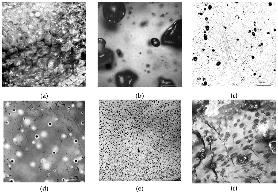
Figure 2.
(a) Dielectric permittivity ε and (b) tanδ versus frequency of composites based on colloidal liquids: black – unfilled PPR, olive – PPR + magnetic liquid, magenta – PPR + Aquadag.
Figure 2.
(a) Dielectric permittivity ε and (b) tanδ versus frequency of composites based on colloidal liquids: black – unfilled PPR, olive – PPR + magnetic liquid, magenta – PPR + Aquadag.
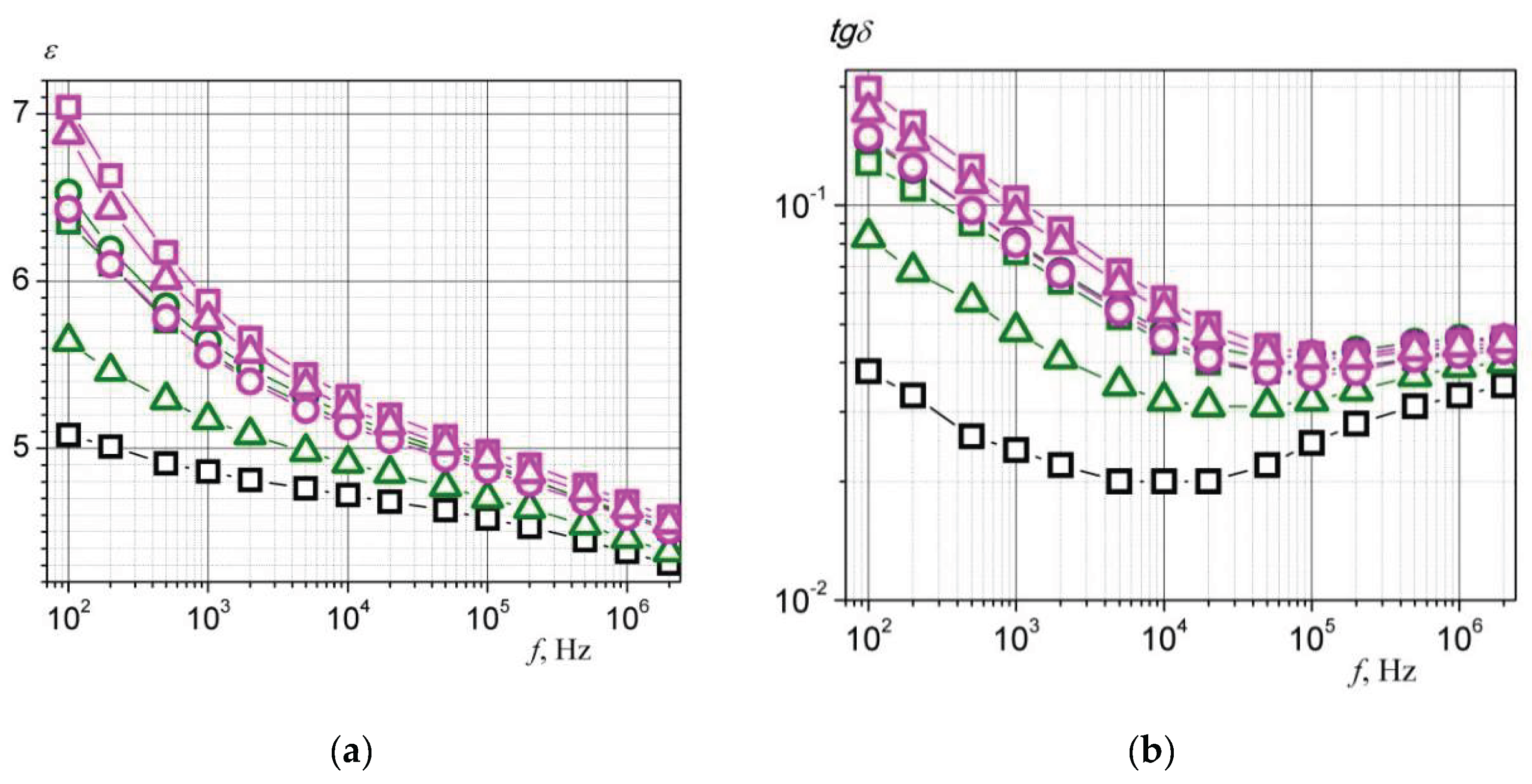
Figure 3.
(a) Dielectric permittivity ε and (b) tanδ versus frequency of composites based on aqueous NaCl solutions: black – unfilled PPR, green – PPR + 1.5% NaCl, red – PPR + 13% NaCl, blue – PPR + 26% NaCl.
Figure 3.
(a) Dielectric permittivity ε and (b) tanδ versus frequency of composites based on aqueous NaCl solutions: black – unfilled PPR, green – PPR + 1.5% NaCl, red – PPR + 13% NaCl, blue – PPR + 26% NaCl.
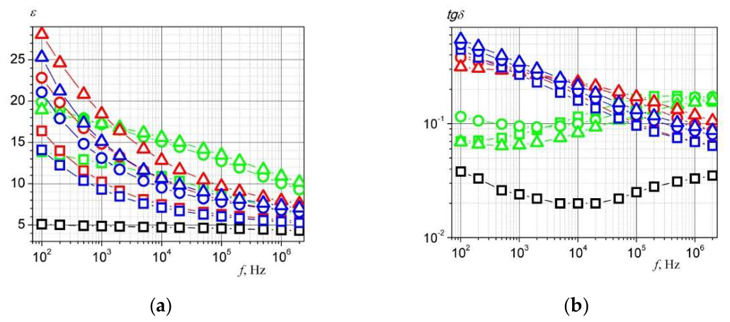
Figure 4.
(a) Dielectric permittivity ε and (b) tanδ versus frequency of composites based on PPR, the “water-in-oil” system, and powder fillers: black- unfilled PPR, orange- PPR + water-in-oil system (MgSO₄ + PVP et al.), cyan- PPR + water-in-oil system + KNbO₃, purple- PPR + water-in-oil system + Fe.
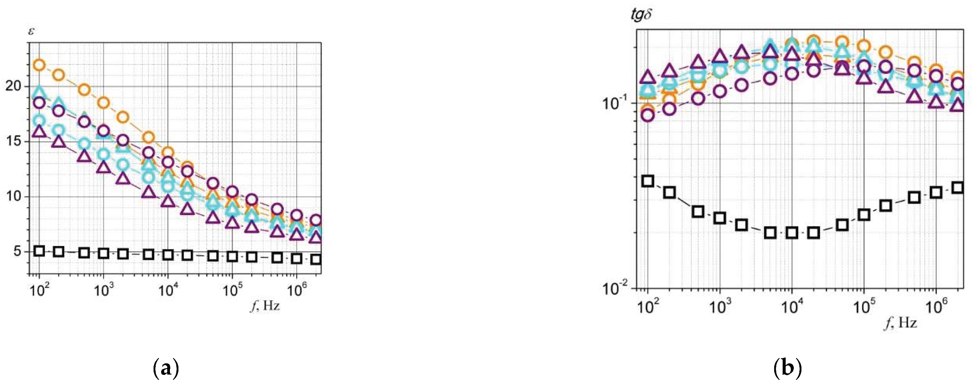

Table 1.
Electrophysical characteristics of composites based on colloidal liquids.
| Composition | Mixing technology | h, (mm) | ε(tgδ) | ρV, 1011 (Ω·m) | Microwave coefficients (25.86–37.5 GHz), rel. units | |||||
| 1 kHz | 1 MHz | 10 V | 100 V | 500 V | T | R | L | |||
| PPR | USD | 1.66±0.01 | 4.86 (0.024) | 4.38 (0.033) | 4.8±0.1 | 4.7±0.1 | 4.4±0.1 | 0.81 | 0.16 | 0.03 |
| PPR + ML | USD | 1.61±0.02 | 5.58 (0.076) | 4.61 (0.043) | 3.9±0.2 | 4.0±1.0 | 3.1±0.1 | 0.79 | 0.17 | 0.04 |
| PPR + ML | OHMS 3500 rpm | 1.72±0.03 | 5.64 (0.081) | 4.60 (0.046) | 1.0±0.03 | 0.98±0.02 | 0.72±0.004 | 0.81 | 0.16 | 0.03 |
| PPR + ML | OHMS 1750 rpm | 1.65±0.02 | 5.17 (0.048) | 4.46 (0.039) | 2.3±0.04 | 2.2±0.04 | 2.0±0.02 | 0.80 | 0.17 | 0.03 |
| PPR + АD | USD | 1.62±0.01 | 5.88 (0.104) | 4.68 (0.045) | 0.93±0.02 | 0.85±0.02 | 0.62±0.004 | 0.78 | 0.15 | 0.07 |
| PPR + АD | OHMS 3500 rpm | 1.66±0.02 | 5.56 (0.080) | 4.59 (0.042) | 1.3±0.04 | 1.2±0.03 | 0.89±0.01 | 0.79 | 0.16 | 0.04 |
| PPR + АD | OHMS 1750 rpm | 1.61±0.02 | 5.77 (0.095) | 4.64 (0.044) | 0.88±0.02 | 0.82±0.01 | 0.62±0.005 | 0.79 | 0.15 | 0.06 |
Table 2.
Electrophysical characteristics of composites based on aqueous NaCl solutions.
| Composition | Mixing technology | h, (mm) | ε(tgδ) | ρV, 1011 (Ω·m) | Microwave coefficients (25.86–37.5 GHz), rel. units | |||||
| 1 kHz | 1 MHz | 10 V | 100 V | 500 V | T | R | L | |||
| PPR | USD | 1.66±0.01 | 4.86 (0.024) | 4.38 (0.033) | 4.8±0.1 | 4.7±0.1 | 4.4±0.1 | 0.81 | 0.16 | 0.03 |
| PPR 1.5% NaCl | USD | 1.65±0.01 | 12.5 (0.081) | 6.74 (0.169) | 8.8±0.4 | 8.8±0.4 | 7.2±0.2 | 0.72 | 0.14 | 0.14 |
| PPR 1.5% NaCl | OHMS 3500 rpm | 1.79±0.04 | 17.2 (0.095) | 10.1 (0.170) | 062±0.002 | 0.53±0.002 | 0.42±0.001 | 0.59 | 0.14 | 0.27 |
| PPR 1.5% NaCl | OHMS 1750 rpm | 1.69±0.04 | 17.3 (0.065) | 10.9 (0.154) | 11±0.5 | 10±0.3 | 9.1±0.2 | 0.53 | 0.19 | 0.28 |
| PPR 13% NaCl | USD | 1.68±0.02 | 10.2 (0.295) | 5.62 (0.070) | 0.37±0.001 | 0.26±0.001 | 0.16±0.001 | 0.64 | 0.18 | 0.18 |
| PPR 13% NaCl | OHMS 3500 rpm | 1.74±0.04 | 14.8 (0.287) | 6.81 (0.098) | 0.84±0.007 | 0.73±0.003 | 0.54±0.002 | 0.61 | 0.18 | 0.21 |
| PPR 13% NaCl | OHMS 1750 rpm | 1.63±0.01 | 18.4 (0.282) | 7.93 (0.119) | 0.46±0.003 | 0.38±0.002 | 0.31±0.001 | 0.57 | 0.19 | 0.24 |
| PPR 26% NaCl | USD | 1.66±0.01 | 9.30 (0.268) | 5.40 (0.069) | 0.72±0.003 | 0.46±0.001 | 0.18±0.001 | 0.63 | 0.19 | 0.18 |
| PPR 26% NaCl | OHMS 3500 rpm | 1.66±0.02 | 13.1 (0.312) | 6.80 (0.086) | 0.25±0.001 | 0.17±0.001 | 0.099±0.0003 | 0.61 | 0.19 | 0.20 |
| PPR 26% NaCl | OHMS 1750 rpm | 1.70±0.02 | 15.1 (0.345) | 7.33 (0.094) | 0.4±0.001 | 0.16±0.001 | 0.091±0.0003 | 0.61 | 0.18 | 0.21 |
Table 3.
Electrophysical characteristics of composites based on PPR, the “water-in-oil” system, and powder fillers.
Table 3.
Electrophysical characteristics of composites based on PPR, the “water-in-oil” system, and powder fillers.
| Composition | Mixing technology | h, (mm) | ε(tgδ) | ρV, 1011 (Ω·m) | Microwave coefficients (25.86–37.5 GHz), rel. units | |||||
| 1 kHz | 1 MHz | 10 V | 100 V | 500 V | T | R | L | |||
| PPR | USD | 1.66±0.01 | 4.86 (0.024) | 4.38 (0.033) | 4.8±0.1 | 4.7±0.1 | 4.4±0.1 | 0.81 | 0.16 | 0.03 |
| PPR +MgSO4 + PVP | OHMS 3500 rpm | 1.64±0.01 | 18.5 (0.148) | 7.92 (0.150) | 6.2±0.02 | 6.5±0.02 | 6.0±0.02 | 0.68 | 0.16 | 0.16 |
| PPR+MgSO4 + PVP - | OHMS 1750 rpm | 1.64±0.01 | 15.9 (0.151) | 7.62 (0.129) | 1.0±0.05 | 1.0±0.03 | 0.87±0.003 | 0.65 | 0.17 | 0.18 |
| PPR+MgSO4 + PVP KNbO3 | OHMS 3500 rpm | 1.63±0.01 | 13.9 (0.150) | 7.12 (0.119) | 0.82±0.003 | 0.67±0.001 | 0.64±0.002 | 0.66 | 0.18 | 0.16 |
| PPR+MgSO4 + PVP KNbO3 | OHMS 1750 rpm | 1.64±0.01 | 15.7 (0.170) | 7.19 (0.110) | 0.87±0.003 | 1.5±0.02 | 1.3±0.04 | 0.69 | 0.16 | 0.15 |
| PPR+MgSO4 + PVP Fe | OHMS 3500 rpm | 1.65±0.01 | 16.0 (0.116) | 8.33 (0.140) | 3.5±0.06 | 3.5±0.06 | 3.4±0.05 | 0.63 | 0.17 | 0.20 |
| PPR+MgSO4 + PVP Fe | OHMS 1750 rpm | 1.62±0.02 | 12.6 (0.176) | 6.45 (0.100) | 0.16±0.002 | 0.17±0.001 | 0.15±0.001 | 0.72 | 0.18 | 0.10 |
Disclaimer/Publisher’s Note: The statements, opinions and data contained in all publications are solely those of the individual author(s) and contributor(s) and not of MDPI and/or the editor(s). MDPI and/or the editor(s) disclaim responsibility for any injury to people or property resulting from any ideas, methods, instructions or products referred to in the content. |
© 2026 by the authors. Licensee MDPI, Basel, Switzerland. This article is an open access article distributed under the terms and conditions of the Creative Commons Attribution (CC BY) license (http://creativecommons.org/licenses/by/4.0/).
Copyright: This open access article is published under a Creative Commons CC BY 4.0 license, which permit the free download, distribution, and reuse, provided that the author and preprint are cited in any reuse.