

Submitted:
25 August 2026
Posted:
26 August 2026
You are already at the latest version
Abstract
In short lab slots, class time is often consumed by interconnect mistakes and intermittent boots rather than by control logic. PiCar Mini 2WD is an open two-wheel-drive (2WD) lab stack for Python-first embedded courses: a single-board interconnect contract, an eight-chapter MicroPython path with observable exits, and a reprintable kit cost on the order of USD 5–6. An ESP32-C3 SuperMini seats on a custom driver board with connectorized motors, battery, and ultrasonic sensing; the board encodes a strap-safe pin contract (GPIO2 / 8 / 9 free of peripherals; left/right buttons and LEDs aligned with the physical layout). Firmware progresses from flashing to modular autostart and pairs with a public web tutorial so instructors can stop at differential drive or an integrated demo without republishing the pin map. Core materials support one-kit-per-student procurement; design files and chapter firmware are released under CERN-OHL-P-2.0 (hardware) and MIT (software), with a citable Zenodo archive at DOI 10.5281/zenodo.22088329 [8]. Bench checks confirm functional readiness across indicators, buttons, motion, ranging, and a combined demo.
Keywords:
educational robotics
; ESP32-C3
; MicroPython
; 2WD mobile robot
; open hardware
; pin contract
; STEM education
; low-cost lab kit
; differential drive
1. Introduction
Introductory courses in embedded sensing and actuation need platforms that students can assemble, program, and debug within limited lab time. A familiar failure pattern is that two kits built from the same shopping list behave differently: one boots and enumerates over USB, another enters an opaque download or brown-out loop because a motor or LED was wired onto a chip strap pin, or because a breadboard H-bridge and a boost module share an improvised ground. Instructors then spend the slot on electrical archaeology instead of differential drive, PWM, or reactive sensing.
Commercial kits are available, yet many either hide the electrical design behind proprietary boards or require C/C++ toolchains that increase the cognitive load for learners who already know desktop Python. MicroPython on Wi-Fi-capable microcontrollers offers a middle path: students keep Python syntax while gaining direct access to GPIO, PWM, and sensors [1,2]. Two-wheel-drive (2WD) chassis with TT gear motors remain a practical base for those topics [6,7]. The limiting factor is often the driver and interconnect layer—discrete modules, unclear pin maps, and collisions with strap pins.
This work contributes PiCar Mini 2WD, an open lab stack defined as a single-board interconnect contract + MicroPython chapter path + reprintable one-kit-per-student cost, with four coordinated parts:
- Interconnect variance control: a purpose-designed driver PCB consolidates motor drive, power conditioning, indicators, buttons, and ultrasonic headers around an ESP32-C3 SuperMini, with connectorized assembly so parallel sections share one electrical baseline and lab time shifts from wiring diagnosis to control logic.
- Strap-safe pin contract (primary engineering differentiator): ESP32-C3 boot constraints are encoded in the board-level map—GPIO2, GPIO8, and GPIO9 remain free of peripheral loads; motors and HMI use non-strap pins; left/right buttons and LEDs match the physical layout—so predictable boot and download behavior is a deliverable rather than an oral reminder to “check the datasheet.”
- Curriculum–hardware isomorphism: an eight-chapter MicroPython sequence with chapter-level observable outcomes ends in a modular main.py suitable for autostart demos, released with documentation and a public web tutorial; instructors may stop at Chapter 5 or Chapter 7/8 without changing the pin contract. Thonny and mpremote support low-friction deploy.
- One-kit-per-student open stack: an official pin map and online materials shorten preparation; a core bill of materials (BOM) on the order of USD 5–6, plus MIT / CERN-OHL-P licensing and a Zenodo DOI, places dense classroom procurement and departmental reprinting in a feasible region. Figure 1 and Section 6 develop teaching convenience and cost.
The remainder of this paper describes related context and a platform comparison (Section 2), system design (Section 3), software and teaching flow (Section 4), functional validation with a summary table (Section 5), discussion and open release (Section 6), limitations and next steps (Section 7), and conclusions (Section 8).
2. Related Context and Platform Comparison
Educational mobile robots span Arduino-class boards, Raspberry Pi companions, and ESP32-family SoCs. ESP32-C3 provides RISC-V cores, Wi-Fi/BLE, and native USB options in compact modules such as SuperMini, which fit dense student kits [3]. MicroPython firmware images for Espressif chips enable REPL-centric labs and file-based deployment; instructors commonly use Thonny for interactive editing [4] and mpremote from the MicroPython toolchain for script deploy [1]. Open-hardware licensing (e.g., CERN OHL) supports institutional reprinting of boards for multi-section courses [5].
Table 1 situates PiCar Mini 2WD among common classroom choices at the same decision point (horizontal selection, not an internal revision history). Cost orders are indicative and depend on region and quantity; the PiCar Mini figure is the published core-kit estimate for this design.
Figure 1 answers the two questions instructors usually ask first—what does it cost, and can I teach a coherent path on it?—as paired contracts: cost layers on the left, curriculum path on the right.
Prior kits often separate an H-bridge module, a boost converter, and breadboarded LEDs or switches. Integration onto one PCB reduces assembly variance and clarifies the “official” pin map for instructors. PiCar Mini 2WD is positioned as a single-board driver + MicroPython curriculum stack; teaching convenience and price are expanded once in Section 6.
3. System Design
3.1. Architecture
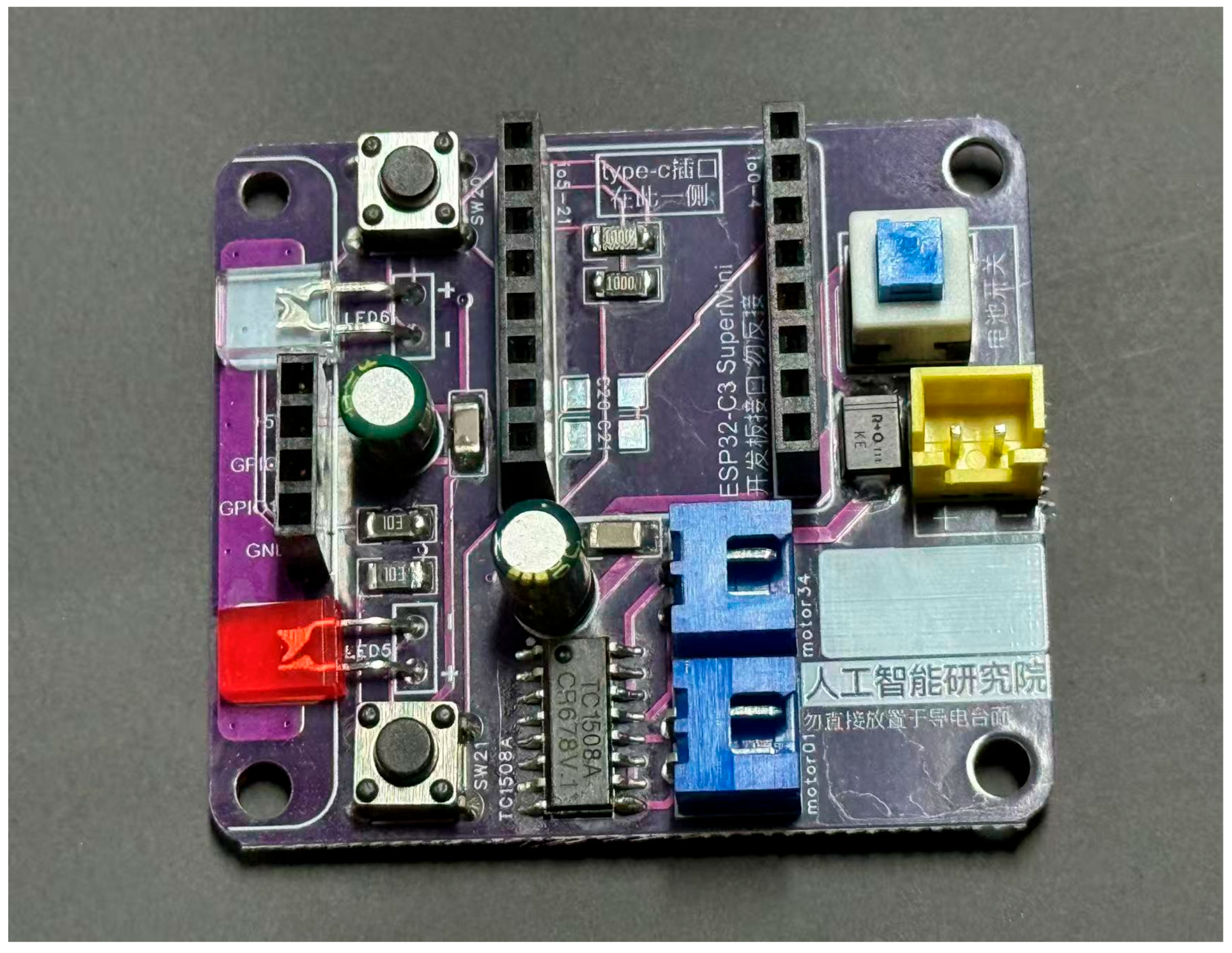
The design center is the pin contract and connectorized interconnect: students and teaching assistants debug against one official map (Table 2) rather than ad-hoc wiring. Implementation details (power rail, H-bridge mapping, HMI polarity) follow that contract.
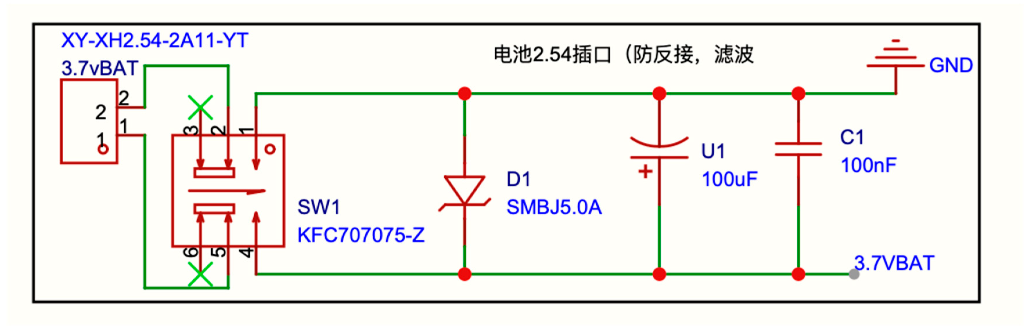
Figure 2 shows the assembled vehicle used for bring-up and classroom demos. The ESP32-C3 SuperMini plugs into a dual-row header on the driver board. Two TT motors connect through XH2.54 headers; a caster completes the 2WD chassis. An HC-SR04 ultrasonic module (wide-voltage 3.3–5 V variant recommended) uses a board 4P socket. A single 3.7 V lithium cell feeds a protected battery rail (3.7VBAT) after a panel switch, TVS, and decoupling network.
Figure 2.
Assembled PiCar Mini 2WD (front view). Assembled PiCar Mini 2WD for first-lab orientation: ultrasonic module forward, driver board amidships, ESP32-C3 SuperMini seated on headers.
Figure 2.
Assembled PiCar Mini 2WD (front view). Assembled PiCar Mini 2WD for first-lab orientation: ultrasonic module forward, driver board amidships, ESP32-C3 SuperMini seated on headers.
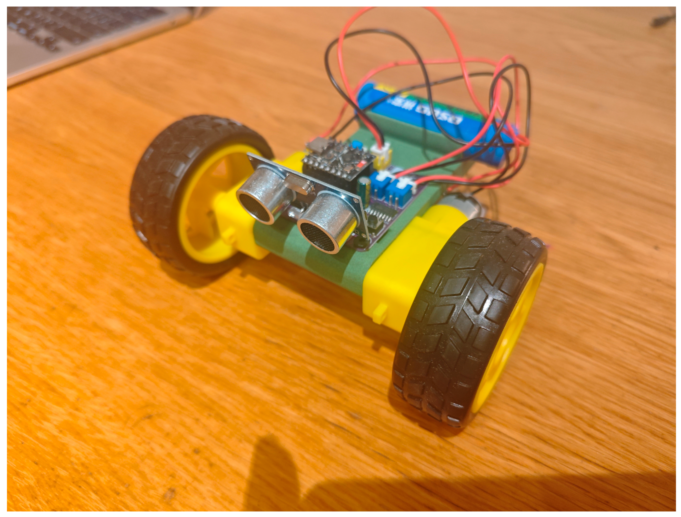
Figure 3.
Driver board, front side. Driver board (front): power path, TC1508A, LEDs, switches, and connectors—the physical counterpart of the official pin map in Table 2.
Figure 3.
Driver board, front side. Driver board (front): power path, TC1508A, LEDs, switches, and connectors—the physical counterpart of the official pin map in Table 2.
3.2. Power Path
Battery voltage supplies the TC1508A motor driver VDD and the SuperMini 5V/VIN wide-range input without an intermediate boost stage on this board. This simplifies the rail and avoids contention between an onboard regulator output and USB VBUS during debugging. Classroom procedure prefers USB attach first, then battery enable, with RESET available if enumeration stalls.
Figure 4.
Battery input protection and filtering. Schematic excerpt: battery connector, switch, TVS, and 3.7VBAT rail.
Figure 4.
Battery input protection and filtering. Schematic excerpt: battery connector, switch, TVS, and 3.7VBAT rail.
3.3. Motor Drive
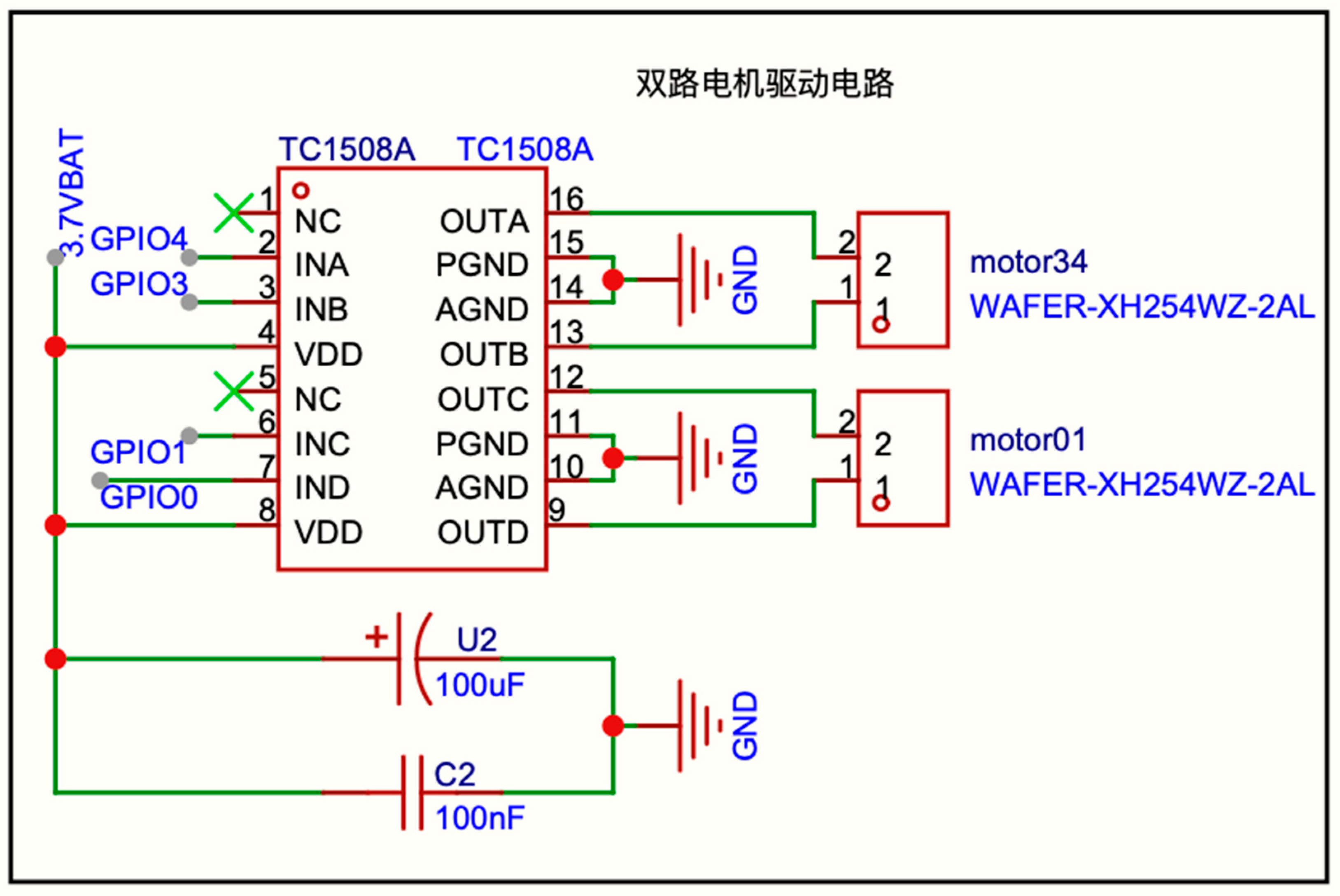
A TC1508A dual H-bridge accepts four logic inputs. Each motor uses a PWM/LOW complementary pair for forward and reverse, dual LOW for coast, and dual HIGH for brake. Left motor mapping is GPIO1/GPIO0; right motor mapping is GPIO4/GPIO3. On ESP32-C3, GPIO0 is not a strap pin, so it may safely participate in motor PWM.
Figure 5.
TC1508A motor interface. Schematic excerpt: TC1508A to motor headers motor01 (left) and motor34 (right).
Figure 5.
TC1508A motor interface. Schematic excerpt: TC1508A to motor headers motor01 (left) and motor34 (right).
3.4. Indicators, Buttons, and Ranging
ESP32-C3 boot constraints are encoded in the board-level pin contract: GPIO2, GPIO8, and GPIO9 remain free of peripheral loads; motors and human–machine interfaces use non-strap pins; left/right soft buttons and status LEDs match the physical layout [3]. Measured board layout (software and teaching materials follow measurement):
| Side | Soft button | Status LED |
| Left | SW21 → GPIO21 (active-low) | LED5 red → GPIO5 (active-high) |
| Right | SW20 → GPIO20 (active-low) | LED6 green → GPIO6 (active-high) |
Ultrasonic Trigger uses GPIO7; Echo uses GPIO10.
3.5. GPIO Summary
Table 2 is the production pin map used by firmware and documentation—the deliverable interface against which labs are written and graded.
4. Software Stack and Teaching Sequence
Firmware targets MicroPython builds for ESP32_GENERIC_C3 (classroom reference: v1.27.0). Students flash with Thonny or esptool, then run scripts over USB REPL / mpremote.
The open repository organizes examples into eight chapters aligned with a web tutorial (Figure 1B). Table 3 lists the focus and the observable outcome that lets a teaching assistant verify progress by watching LEDs, hearing motors, or reading a short REPL printout.
Chapter 8 factors pin constants into config.py and exposes Motor/Car, Ultrasonic, Button, and StatusLed modules so the main loop remains readable for assessment demos. Instructors can truncate the sequence by lab hour—for example ending at Chapter 5 (differential drive) or Chapter 7/8 (integrated demo)—without changing the pin contract.
5. Functional Validation
Validation used MicroPython v1.27.0 on an ESP32-C3 SuperMini mounted on the driver board, with USB serial control (mpremote) and battery enabled after USB attach where motors were exercised. Table 4 is a functional-readiness evidence block for adoption decisions: it reports bench and development-vehicle behavior under the protocols listed.
GPIO and HMI. LED scripts confirmed polarity and placement. Fifteen-second button tests recorded rising-edge counts on SW20/SW21; toggle demos mapped left button→red LED and right button→green LED.
Motion. Single-motor sweeps at duty percentages 40/70/100 verified both wheels in forward and reverse. The eight-step regression exercised left/right alone, then whole-vehicle forward, reverse, left turn, and right turn with mandatory stop/deinit cleanup.
Ranging. Fifty HC-SR04 samples produced stable centimeter readings under static conditions (approximately 16–23 cm for the bench geometry used); combined LED feedback switched between green (range ≥ threshold) and red blinking (near field), including sub-10 cm near-field periods during occlusion tests. In a separate ranging-plus-LED run, reported distances spanned roughly 4–140 cm as the probe–obstacle geometry changed, confirming that the cue logic tracks large swings as well as the static band.
Integrated demo. Button-driven three-state wheel machines operated concurrently with ultrasonic lighting in a single polling loop, matching the Chapter 7/8 teaching endpoint.
Together these checks show that the electrical map and MicroPython drivers form a coherent lab stack from first blink to autostart behavior, supporting immediate classroom adoption on functional grounds.
6. Discussion and Open Release
Integrating drive, power, and HMI on one PCB shifts student effort from wiring diagnosis toward control logic and sensing. Encoding Espressif boot constraints into the pin contract—GPIO2 / 8 / 9 free, non-strap motor/HMI maps, left/right layout aligned with the board—makes predictable boot and download a board-level property that short labs can rely on. MicroPython preserves continuity with Python-first curricula while still exposing PWM and timing APIs needed for motors and sonar.
Teaching convenience (curriculum–hardware isomorphism). The platform ships as a classroom-ready bundle: a fixed pin map (Table 2), connectorized chassis and sensors, an eight-chapter progression with observable outcomes (Table 3), and a web tutorial aligned with the repository (Figure 1B). Weekly endpoints can be Chapter 5 or Chapter 7/8 without republishing pin tables. The student toolchain centers on USB and free IDEs (Thonny GUI or mpremote CLI). Teaching assistants can verify most chapter exits by lights, motor sound, or a short REPL printout.
Price advantage (one-kit-per-student open stack). The published core BOM places the MCU module, driver-board materials, TT chassis, battery, and ultrasonic module at about USD 5–6 in aggregate (Figure 1A; varying with fabrication quantity, component channels, and chassis choice). MIT software and CERN-OHL-P-2.0 hardware licenses allow departments to fabricate and redistribute boards. Relative to Raspberry Pi companion cars, the microcontroller-class BOM leaves budget for one kit per student; relative to closed commercial robots, CERN-OHL-P reprinting keeps procurement inside institutional workshops when needed.
Open materials. Hardware design exports, BOM CSV, chapter firmware, and documentation are published at:
- Zenodo (v1.1.0 DOI): https://doi.org/10.5281/zenodo.22088329
- Zenodo concept DOI (all versions): https://doi.org/10.5281/zenodo.22088328
- Project site: https://www.pythonguru.cn/research/picar-mini-2wd-v1-1/
Software is MIT-licensed; hardware design materials use CERN-OHL-P-2.0. Gerber archives may be added as tagged releases when fabrication packages are finalized.
7. Limitations and Forward Agenda
Table 4 reports functional behavior on instrumented benches and development vehicles. The next evaluation track is controlled multi-section classroom study of completion time, failure modes, and learning gains. Motor characterization (torque, current, dead-band) and closed-loop wheel odometry are natural extensions once encoder-equipped gearmotors are adopted. Lane keeping and vision are intended for companion compute stacks that reuse the same differential-drive interface.
8. Conclusions
PiCar Mini 2WD delivers a classroom-adoptable triad: a strap-safe single-board pin contract, a curriculum–hardware isomorphic eight-chapter MicroPython path with public tutorial support, and a one-kit-per-student open stack (MIT / CERN-OHL-P-2.0) at a core BOM near USD 5–6. The design targets Python-first embedded and introductory robotics labs that need reproducible interconnects, predictable boot behavior, and dense kit economics. Immediate next work is multi-section classroom evaluation of completion time and failure modes, followed by encoder-ready motion characterization on the same differential-drive interface.
Author Contributions
Conceptualization, hardware architecture, and manuscript drafting, Q.L.; hardware bring-up, firmware examples, and validation experiments, Z.S., H.P., X.A., S.L., B.L. and Q.Y.; supervision and corresponding author, Q.L. All authors have read and agreed to the published version of the manuscript.
Data and Code Availability
Firmware examples and documentation: https://github.com/modalfuse/picar-mini-2wd Archived release with DOI (v1.1.0): https://doi.org/10.5281/zenodo.22088329 Concept DOI (all versions): https://doi.org/10.5281/zenodo.22088328 Interactive tutorial: https://www.pythonguru.cn/research/picar-mini-2wd-v1-1/micropython-2wd-tutorial/
Acknowledgments
The authors thank colleagues and students who participated in hardware bring-up and tutorial dry-runs for the PiCar Mini platform.
Conflicts of Interest
The authors declare no conflict of interest.
References
- MicroPython. MicroPython Documentation. Available online: https://docs.micropython.org/ (accessed on 25 August 2026).
- Bell, C. MicroPython for the Internet of Things; Apress: Berkeley, CA, USA, 2017. [Google Scholar] [CrossRef]
- Espressif Systems. ESP32-C3 Series Datasheet, Version 2.4; Espressif Systems: Shanghai, China. Available online: https://www.espressif.com/sites/default/files/documentation/esp32-c3_datasheet_en.pdf (accessed on 25 August 2026).
- Annamaa, A. Introducing Thonny, a Python IDE for learning programming. In Proceedings of the 15th Koli Calling Conference on Computing Education Research; ACM: New York, NY, USA, 2015; pp. 117–121. [Google Scholar] [CrossRef]
- CERN. CERN Open Hardware Licence Version 2 – Permissive (CERN-OHL-P). Available online: https://cern-ohl.web.cern.ch/ (accessed on 25 August 2026).
- Siegwart, R.; Nourbakhsh, I.R.; Scaramuzza, D. Introduction to Autonomous Mobile Robots, 2nd ed.; MIT Press: Cambridge, MA, USA, 2011; ISBN 978-0-262-01535-6. [Google Scholar]
- Jones, J.L.; Seiger, B.A.; Flynn, A.M. Mobile Robots: Inspiration to Implementation, 2nd ed.; A K Peters/CRC Press: New York, NY, USA, 1998. [Google Scholar] [CrossRef]
- Liu, Q.; Sun, Z.; Peng, H.; An, X.; Lu, S.; Li, B.; Yang, Q. PiCar Mini 2WD: Open ESP32-C3 MicroPython Educational Robot (driver board v1.1), version 1.1.0; Zenodo, 2026. [CrossRef]
Figure 1.
Cost stack and teaching path for PiCar Mini 2WD. PiCar Mini 2WD at a glance: (A) cost contract—core BOM layers targeting about USD 5–6 per kit; (B) curriculum contract—eight-chapter MicroPython path with optional stop points at Chapters 5, 7, or 8 without changing the pin contract.
Figure 1.
Cost stack and teaching path for PiCar Mini 2WD. PiCar Mini 2WD at a glance: (A) cost contract—core BOM layers targeting about USD 5–6 per kit; (B) curriculum contract—eight-chapter MicroPython path with optional stop points at Chapters 5, 7, or 8 without changing the pin contract.
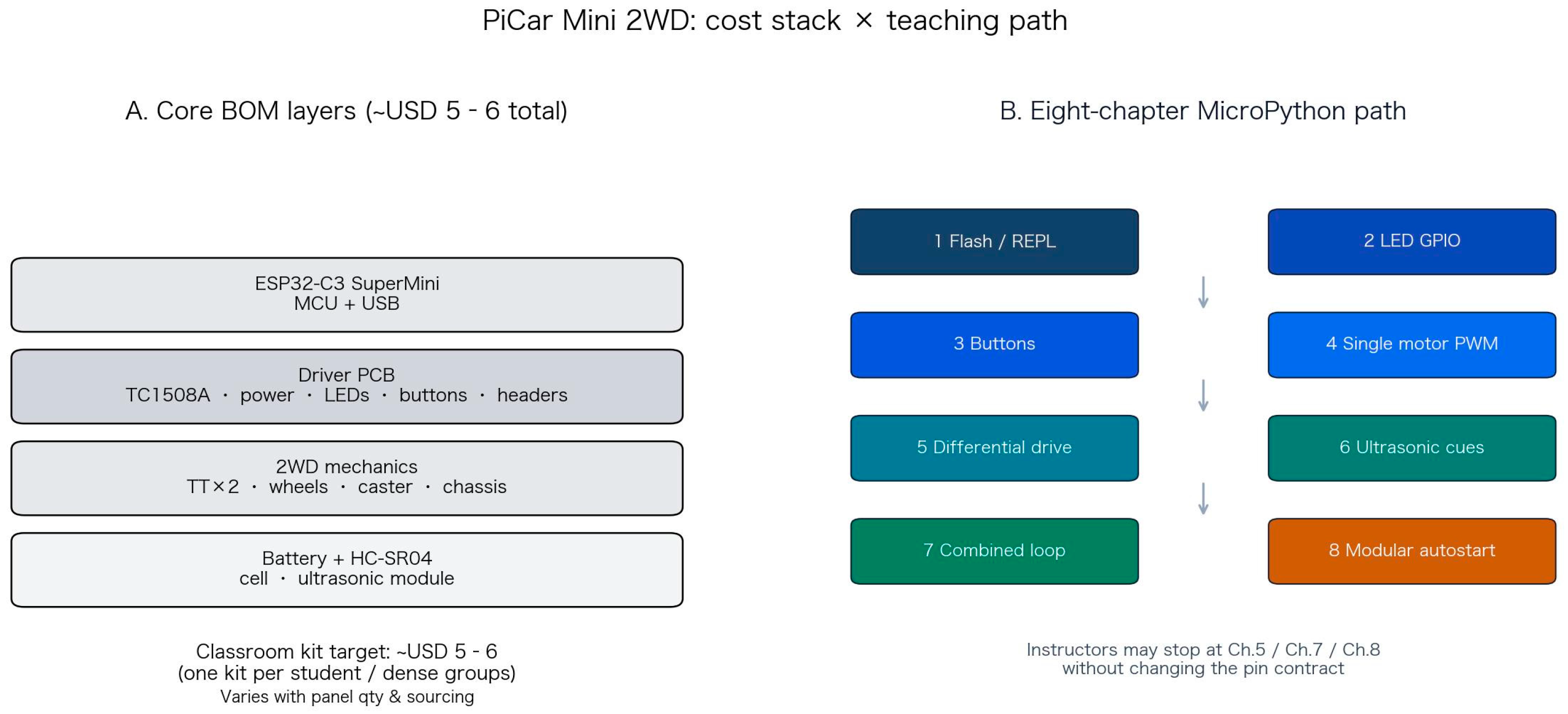

Table 1.
Classroom platform classes versus PiCar Mini 2WD (indicative selection table).
| Platform class | Primary student language | Open schematic / official pin map | Strap or boot hazards documented in the kit | Typical core kit cost order | Chaptered curriculum + public web tutorial |
| Discrete MCU + breadboard H-bridge / boost | C/C++ or Arduino IDE | Often partial or student-drawn | Rarely; strap conflicts are a common lab surprise | Low to mid | Highly variable by instructor |
| Raspberry Pi companion car | Python on Linux | Partial; SBC pinout ≠ motor shield | Different failure modes (OS, power, SD) | Higher (SBC alone often exceeds this kit) | Often project-based, not GPIO-first |
| Commercial closed educational robot | Vendor IDE or mixed | Usually closed | Opaque to instructors | Mid to high | Vendor courses; reprinting restricted |
| PiCar Mini 2WD (this work) | MicroPython | Yes (CERN-OHL-P design + docs) | Yes (GPIO2 / 8 / 9 kept free) | ~USD 5–6 | Yes (eight chapters + web tutorial) |
Table 2.
GPIO assignment on the driver board (validated on hardware); strap pins left unused by peripherals.
Table 2.
GPIO assignment on the driver board (validated on hardware); strap pins left unused by peripherals.
| GPIO | Function |
| 0 / 1 | Left motor (pair) |
| 3 / 4 | Right motor (pair) |
| 5 | LED5 red (left) |
| 6 | LED6 green (right) |
| 7 | Ultrasonic Trig |
| 10 | Ultrasonic Echo |
| 20 | SW20 (right button) |
| 21 | SW21 (left button) |
| 2, 8, 9 | Strap; left unused by peripherals |
Table 3.
Eight-chapter MicroPython sequence and observable outcomes (curriculum–hardware isomorphism).
Table 3.
Eight-chapter MicroPython sequence and observable outcomes (curriculum–hardware isomorphism).
| Chapter | Focus | Observable outcome |
| 1 | Tooling and firmware image | REPL print |
| 2 | GPIO output | Left/right LED blink |
| 3 | Active-low buttons | Edge-triggered LED toggles |
| 4 | PWM and single motor | Speed steps, forward/reverse |
| 5 | Differential drive | Forward, reverse, in-place turns |
| 6 | Ultrasonic ranging | Distance print; far-green / near-red cues |
| 7 | Multi-module loop | Buttons drive wheels; ranging drives lights |
| 8 | Modular project | config / drivers / main.py autostart |
Table 4.
Functional validation summary (instrumented bench and development vehicle).
| Check | Protocol | Observed outcome |
| LED polarity and left/right color | Blink scripts on GPIO5 / GPIO6 | Left = red (LED5), right = green (LED6), active-high as documented |
| Soft buttons | 15 s rising-edge count on SW20 / SW21; toggle demos | Edges registered; left button → red LED, right button → green LED |
| Single-motor PWM | Duty percentages 40 / 70 / 100, forward and reverse, both wheels | Both wheels respond at all three duties in both directions |
| Whole-vehicle regression | Eight-step sequence: L alone, R alone, forward, reverse, left turn, right turn, then stop / deinit | All motion steps completed; mandatory cleanup executed |
| Ultrasonic static ranging | 50 HC-SR04 samples under static bench geometry | Stable centimeter readings in an approximate 16–23 cm band for the fixed setup; readings track subsequent occlusion |
| Distance-coded lighting | Far / near threshold demo concurrent with ranging | Green when range ≥ threshold; red blinking in near field, including sub-10 cm periods |
| Integrated Chapter 7/8 endpoint | Button three-state wheel machine (stop → forward → reverse) + ultrasonic lighting in one polling loop | Both behaviors concurrent without pin remapping |
Disclaimer/Publisher’s Note: The statements, opinions and data contained in all publications are solely those of the individual author(s) and contributor(s) and not of MDPI and/or the editor(s). MDPI and/or the editor(s) disclaim responsibility for any injury to people or property resulting from any ideas, methods, instructions or products referred to in the content. |
© 2026 by the authors. Licensee MDPI, Basel, Switzerland. This article is an open access article distributed under the terms and conditions of the Creative Commons Attribution (CC BY) license (http://creativecommons.org/licenses/by/4.0/).
Copyright: This open access article is published under a Creative Commons CC BY 4.0 license, which permit the free download, distribution, and reuse, provided that the author and preprint are cited in any reuse.