

Submitted:
21 August 2026
Posted:
24 August 2026
You are already at the latest version
Abstract
Approved conservation projects that remain unimplemented for years require reassessment before site work begins. This study examines the 2012–2014 conservation project for the Selime rock-cut complex as a record set that may be reactivated for future implementation. The project combined a 54-station local Total Station network with laser and manual measurements, restitution drawings, deterioration records, material analyses, and approved restoration drawings. Historical interpretations were graded as C1 direct evidence, C2 strong inference, C3 bounded hypothesis, or C4 unresolved. Technical validity was assessed through historical/spatial basis (H), current risk (R), and operational compatibility (O), while implementation traceability was recorded separately through U. Applied to eight selected components, the framework shows that safety, circulation, platforms, and service decisions require current verification, whereas stratigraphic and reconstructive interventions remain constrained by evidential strength. The study proposes a two-track reactivation framework separating technical validity from implementation traceability for delayed conservation projects under comparable site conditions.
Keywords:
rock-cut heritage
; approved conservation project
; reactivation
; evidence grading
; decision framework
; Cappadocia
1. Introduction
Approved conservation projects reflect the physical condition of a site, available knowledge, regulations, visitor use, and institutional capacity at the time they are prepared. When implementation is delayed for many years, these conditions may no longer be the same. Cracks and surface loss may progress. New safety elements may be added. Visitor flows and service needs may change, as may funding and institutional responsibilities. An earlier conservation-board approval therefore retains its historical and administrative status, but this does not mean that every intervention can still be transferred directly to the present site.
Recent work in archaeological site management shows that older records and plans can remain useful when they are reworked with current data. At the Kondoa rock-art sites, an expired management plan was turned from a static administrative document into an action-oriented and adaptive framework. At Ranchillos, cartographic records from 1956 to 2022 were linked to a UAV-based comparative monitoring system. A classification model developed for cultural heritage in Antarctica has also shown that clear decision categories can support prioritisation when data are incomplete (Silvestri, Prieto-Olavarría, and Chiavazza 2025; Macdonald 2026; Mabie and Chami 2026).
These studies treat documentation and planning as something that can be used again when new evidence becomes available, rather than as a finished product. Recent discussions in Conservation and Management of Archaeological Sites also make another point. Technical and institutional tools cannot replace participatory processes involving local communities, visitors, and other stakeholders (van den Dries, Mason, and van Rooijen 2026). The present study is limited to technical, documentary, and administrative revalidation. It does not assess visitor experience, local values, or the success of participatory management.
The problem is more difficult at rock-cut archaeological sites. Interior spaces may be connected by narrow passages and distributed across several levels. Rock surfaces are irregular, sightlines are often limited, and the geological fabric itself may be fragile. Geometric recording, deterioration assessment, and access planning therefore need to work within the same spatial system. Studies at Gourara and Taşkale also treat documentation in this way: not simply as a record, but as a basis for understanding building phases, physical condition, and management decisions (Belouaar and Hadji 2024; Kilit and Dişli 2023).
This article examines the Selime rock-cut complex through the problem of reactivating an approved conservation project that has remained unimplemented for an extended period. The main research question is straightforward: How can the current validity of a long-delayed approved conservation project be reassessed systematically? Three related questions are considered: (1) how can an earlier coordinate-based documentation system support present-day comparison and the updating of the project; (2) how can historical interpretations, risks, and intervention decisions be distinguished according to different levels of evidence; and (3) how can approved decisions be retained, made conditional, or reformulated when current site conditions, administrative implementation status, and operational requirements are considered together?
2. The Selime Complex and Project Process
This section sets out the spatial and institutional background of the reactivation problem. It covers the historical and architectural character of Selime and the documentation, design, and approval process carried out between 2012 and 2014.
2.1. Spatial and Historical Character of the Site
Selime lies at the northern end of the Peristremma/Ihlara Valley. The complex is cut into a tuff mass and is organised around two courtyards, with lower, middle, and upper levels separated by marked differences in elevation (Figure 1). It covers approximately 3,000 m² and contains stables, kitchens and service spaces, storage areas, reception and ceremonial halls, chapels, and a basilical church (Kalas 2006, 2007; Şahna 2018; Günay 2024). The widely used name “Selime Cathedral” draws attention to the sacred core of the site. Still, the coexistence of productive, representational, and religious spaces makes it difficult to describe the whole complex simply as a monastery or a church (Kalas 2004; Mathews and Daskalakis Mathews 1997).
The rock-cut fabric was reused in different periods. Walls and floors have been lost, some openings were later closed with rubble masonry, and natural erosion has altered many surfaces. Functions and phases can therefore not be identified with the same degree of certainty in every space. The project did not attempt to produce a single definitive restitution. Direct material evidence, formal continuity, stratigraphic distinctions, comparative analogy, and hypothetical limits were instead assessed at different levels of evidential support.
The geographic and topographic setting also means that the spaces cannot be read as isolated units. They form a connected settlement spread across several levels. The location of Selime within Turkey and the Ihlara Valley, the overall form of the rock mass, selected interior spaces, and the relationship between the lower, middle, and upper levels provide the spatial basis for the common coordinate and elevation system discussed in the next section (Figure 1 and Figure 2).
The rock mass as perceived from outside and the character of the interior spaces form part of a multi-level spatial organisation. After establishing the visual and topographic context, the distribution of the rock-cut spaces and their relationships within the rock mass were examined through the measured survey plans. The spatial organisation of the lower, middle, and upper levels is shown together in this context (Figure 2).
2.2. Project Process and Institutional Milestones
The survey, restitution, restoration, and site-planning project was tendered on 18 September 2012. Following the contract and site handover, field and office work was completed on 26 October 2013. The project was approved by the Conservation Board in September 2014, and the project service was administratively closed with the final progress payment dated 10 October 2014.
In the Turkish system, acceptance of the project service, Conservation Board approval, and construction are separate stages. Board approval confirms that the proposed conservation and intervention scheme complied with the relevant regulations at a particular date. It does not automatically initiate funding, a construction tender, or an implementation contract. The administrative material available for this study is limited to the existing records of the project process. Systematic access could not be obtained to the implementation and maintenance files held by the Regional Conservation Board, museum/site authorities, or the Ministry. No construction tender, implementation contract, site handover, or construction progress payment following Board approval was identified in the records examined. The implementation status (U) therefore refers to implementation traceability within the available documentary corpus, not to definitive proof that implementation did not occur. Records held by other institutions may still exist. The main administrative milestones, the evidence associated with them, and their role in the study are summarised chronologically (Table 1).
3. Materials and Methods
This section describes the geodetic and architectural documentation used in the study, the assessment of historical and material data, and the evidence and decision framework used to reassess the approved project decisions.
3.1. Geodetic and Architectural Documentation
The survey network was established in a local coordinate and elevation system using a Total Station. P1 was selected as the main station point on the opposite side of the road, with a clear view of the complex. A total of 54 station points were established. P2, P3, and P4 served as the main control points for the three principal levels. Each new station was tied back to previous points as the instrument was moved, allowing courtyards, façades, and interior spaces to be related within the same spatial system.
Measurements were taken with a Nikon NPR-332 reflectorless electronic total station. The manufacturer specifies a nominal angular accuracy of 5″ and a distance accuracy of ±(3 mm + 2 ppm × D) in precision reflectorless mode (Nikon Corporation n.d.). Network closure calculations, repeated-measurement differences, and field tolerance records are not available in the present research corpus. These nominal instrument specifications were therefore not treated as the achieved accuracy of the field network, and no independent claim is made about its realised geodetic performance. The network is used here as the spatial framework linking plans, sections, elevations, deterioration records, and intervention decisions within a common local coordinate and elevation system.
Eleven room entrances on the lower level, six on the middle level, and thirty-five on the upper level were connected to the main network. Where sightlines allowed, additional points were recorded on façades and interior surfaces. Preliminary plan and section sketches were prepared in the field, and section lines were identified in advance so that measurement density could be increased along them. Details such as stairs, niches, mouldings, floor depressions, openings, and railings were completed using a laser distance meter and steel tape. The method did not produce a full-surface laser scan or a photogrammetric mesh. It provided controlled three-dimensional coordinate data for plans, sections, elevations, and selected architectural details.
Survey data were transferred to the computer at the end of each working day. Inconsistencies found while producing plans and sections were listed and checked again on site the following day. This daily field-office feedback reduced the accumulation of error, particularly in connections between spaces without direct intervisibility and along complex section lines. The final documentation set included plans showing all levels in relation to one another, numerous transverse and longitudinal sections, elevations, and selected architectural details. The main stages of the geodetic and architectural documentation process, the control methods used, and the resulting outputs are summarised together (Table 2).
The workflow was designed to bring rock-cut spaces at different elevations and with limited intervisibility into a single coordinate system (Table 2). It linked measurement, control, and drawing production as successive parts of the same process. The survey therefore did more than record individual spaces. It also established the horizontal and vertical relationships between the lower, middle, and upper levels. The P1 main station and the P2–P4 control points defined for each level connected all 54 stations within a common network. Space entrances, façades, section lines, and architectural details were measured through this system.
The lower, middle, and upper levels can therefore be read together within the same spatial framework, making the horizontal and vertical relationships between rock-cut units at different elevations visible (Figure 2). The survey strategy behind this geometry is shown through the 54-station local network tied to the P1–P4 control points, together with sample plans and sections produced from the coordinate data (Figure 3). This spatial framework also allowed the material, deterioration, and risk data discussed in the following section to be linked to specific spaces, surfaces, and sections.
3.2. Recording of Material, Deterioration, and Risk Data
Metric documentation was assessed together with the condition and deterioration drawings. Field records grouped the main problems into four related categories: surface and material deterioration; water- and moisture-related effects; structural or rock-mass instability; and circulation and fall hazards. Fallen rock fragments, darkening associated with moisture and carbon deposits, flaking, and losses of surface material and joints were recorded as material problems. Open joints, secondary cracks, separated tuff layers, thinned column bases, suspended blocks, and unstable arches and vaults were treated as structural indicators. Water ingress into the spaces and from the upper slopes was also recorded where it appeared to accelerate these processes.
The condition survey did more than identify problems common to the site. Intervention decisions were differentiated at the level of individual spaces. The suspended block between spaces 102–103 and the ceiling of 107, for example, required removable steel shoring. Local stone infill was proposed at the water-damaged and thinned column bases in 107 to distribute the load. Column loss between 117–118, the suspended column and secondary cracks in 216, cracked blocks in the 301–305 group, eroded columns at the entrance to 309, and suspended fragments in 319 were addressed through different combinations of support, stitching, and infill. Visitor access to spaces 405–406 was to be prevented because the floor rock had thinned to about 40 cm in places and was heavily cracked. Loose rock blocks above the complex were treated as a rockfall hazard originating outside the lower levels themselves.
Material decisions were supported by field observations and by the results of thirteen stone, plaster, mortar, joint, and fresco samples examined by the Istanbul Restoration and Conservation Central and Regional Laboratory. The analyses included visual identification; spot tests for protein, oil, and water-soluble salts; calcination analysis based on losses at 105 °C and 550 °C; carbonate assessment; and stereomicroscopic examination of aggregates after acid treatment. The samples were grouped into four categories: CAS gypsum-based, lime-bound, Portland-cement-modified gypsum, and clayey-tuff joint mortars. Gypsum-bound samples were interpreted as earlier materials, lime-bound samples as belonging to a second phase, and cement-modified samples as later interventions. These results helped distinguish original and later material layers and informed the selection of compatible plaster, mortar, and jointing mixtures. The locations, sample types, main analytical results, material groups, and their influence on conservation decisions are summarised in the supplementary material (Supplementary Table S7). The study uses these results as primary project data explaining the material decisions of the approved conservation project, rather than as an independent material-characterisation study.
Visible deterioration alone was not used to determine risk. A small surface loss may affect historical legibility, while a narrow crack can become a direct safety issue when associated with movement in a suspended block or a thin rock floor. Intervention decisions therefore considered the type of evidence, deterioration mechanism, likely consequence, and access conditions together. The relationship between the recorded condition and project decisions is summarised through the main deterioration and risk groups and their corresponding interventions (Table 3).
3.3. Documentary Corpus and Evidential Support
Alongside the geodetic survey, the study examined art-historical and condition reports, deterioration drawings, restitution and restoration drawings, administrative records, and current visual material. Unpublished project documents were treated as part of the primary research corpus and were not included in the academic reference list.
The unit of analysis was not the space as a whole, but a specific historical, spatial, or functional claim. Function, phase, and lost details within the same space may have different levels of support, so each claim was coded separately. Ten pilot cases were selected to cover direct functional evidence, morphological or stratigraphic distinction, typological analogy, relational interpretation, and hypothetical restitution. C1 indicates direct evidence based on preserved and repeatable material or spatial indicators. C2 refers to a strong inference supported by more than one independent indicator. C3 denotes a bounded hypothesis based on limited traces and analogy, clearly identified as hypothetical in the graphic representation. C4 is used when a claim cannot be resolved from the available corpus. These codes do not express numerical probabilities. They indicate the level of evidential support within the documentary corpus examined. The coding guide and the full claim-level matrix are provided in the supplementary material (Supplementary Table S1–S2).
Different types of evidence were not given equal weight. Existing physical traces and the coordinate-based survey served as the primary evidence for geometry and material condition. Historical and comparative sources were used to assess restitution interpretations, while the Conservation Board-approved restoration project provided the basis for identifying proposed interventions and design decisions. Where documents were unclear in detail or did not fully agree, only decisions that could be verified with confidence were coded as definite project components. Elements that remained uncertain in material, detail, or mode of implementation were left unresolved. This avoided treating intermediate design options or insufficiently verified details as final, executable project decisions.
Restitution operations were grouped under functional attribution, formal completion, distinction of later additions, analogical completion, and hypothetical contour. Conservation decisions were assessed under material, structure, circulation, access, entrance-service provision, and monitoring. Keeping these categories separate prevents historical interpretation from automatically determining intervention priority. A space with a well-established function may still require closure because of risk, while a space with an unresolved function may become a conservation priority because of stratigraphic value or fall hazard.
3.4. H–R–U–O Coding Criteria, Decision Rules, and Case Selection
This section defines the operational codes for the H–R–U–O variables, the rules used to read them together, and the criteria used to select the project components on which the framework was tested.
3.4.1. Operational Coding of the Variables
C1–C4 codes are used as the historical/spatial basis (H) only when a component involves a historical or morphological claim. Hx (not applicable) is used for decisions concerned solely with safety, circulation, or programme.
Current risk (R) is classified as R3 critical/emergency, R2 high, R1 moderate, R0 low, and Rx where current data are insufficient. R refers only to present risk. Risk levels recorded in the 2012–2013 project corpus are retained as earlier-condition references and are not substituted for current R codes.
Implementation traceability (U) is recorded separately. U2 indicates a verified link between documentary evidence and a physical intervention. U1 refers to partial implementation or an intervention whose link to the approved project remains uncertain. U0 means that implementation could not be verified in the relevant sources examined. Ux is used where external institutional records are unavailable or the available evidence is insufficient for a decision.
Operational compatibility (O) is coded as O2 when the decision remains compatible with current use, access, and management conditions. O1 indicates that the underlying rationale remains valid but dimensions, capacity, or details need updating. O0 is used for decisions that are outdated or incompatible with current requirements. Ox indicates insufficient current operational data. The full rubric and minimum evidence requirements are given in the supplementary material (Supplementary Table S3).
3.4.2. Final Decision, Priority, and Action Rules
The technical status of a component is determined through H–R–O, independently of implementation traceability. A decision is classified as valid when the historical basis is adequate, where relevant, or Hx applies to a purely safety or programme-related decision; current risk is manageable at R0–R1; operational compatibility is O2; and there is no direct contradiction with current evidence.
A decision is conditionally valid when its basic rationale still holds but at least one of the variables is R2–R3, Rx, O1, or Ox. It is insufficient where H=C4 for a historically based intervention, or where a critical gap in R or O does not allow a defensible technical decision. A decision is invalid where current evidence directly contradicts the earlier assumption or where the design would increase present risk. An unimplemented decision is therefore not automatically a technically invalid one.
Technical status, implementation traceability, priority, and action are recorded separately. R3 normally produces an emergency priority, R2 high, R1 moderate, and R0 low. Visitor exposure or cascading risk at site scale may raise this priority by one level. Rx produces at least a high priority where safety consequences are possible, but only a moderate priority for a purely programmatic component.
U does not lower technical status. It determines the implementation route. A valid decision with U2 is retained and monitored. A valid decision with U0 or Ux is transferred into an updated implementation package. A conditionally valid decision with U0 or Ux must first be remeasured and revised. Where a conditionally valid decision has U1, the existing element must be inspected and either integrated or replaced. Insufficient or invalid decisions are redesigned, replaced, or abandoned regardless of U. The two-track decision rules are summarised in the supplementary material (Supplementary Table S3).
3.4.3. Component Selection and Robustness Check
The eight components form a purposively selected comparative decision set rather than a statistical sample, covering different scales, decision types, risk sources, levels of operational uncertainty, and degrees of historical/spatial evidence (Table 5). Selection was made before assigning final statuses and followed five criteria: (i) traceability in an approved drawing or report; (ii) representation of local, space, and site scales; (iii) coverage of geological/structural safety, circulation, programmatic, stratigraphic, and reconstructive decisions; (iv) variation across H, R, U, and O data conditions; and (v) grouping repeated construction items under a single component. The first six components address safety, circulation, and programme decisions. Removal of the later closure in space 218 and representation of the hypothetical volume 325 were included to test the effect of H on stratigraphic and reconstructive decisions. Hx is used for decisions concerned only with safety or programme, while C1–C4 codes enter the decision process directly where a historical or reconstructive claim is involved. The selection and coverage matrix is provided in the supplementary material (Supplementary Table S4).
A robustness check was carried out using the available data to see whether the decisions were overly dependent on unresolved variables. For each component, the minimum new evidence needed to move the technical status one level upward or downward was recorded separately from the evidence that could change implementation traceability. The critical access closure and upper-slope safety decisions remained technically conditional without a current risk assessment, even under a more optimistic assumption about implementation status. The three-level route and entrance-service programme did not provide a sufficient basis for decision-making without current data on risk, capacity, and management. Local gratings/railings and interior platforms also remained conditional because they depend on new measurement and a verifiable link to the approved project. The robustness check and the blank recoding template prepared for use by another evaluator are provided in the supplementary material (Supplementary Table S5–S6).
3.5. Preliminary Visual Check of Implementation Status and Study Limitations
Current field data consist of six photographs and one video recorded by site staff on 19 July 2026. The images cover the entrance, the first ascent, short timber steps, railings at the upper levels, and the general topography. The analysis was not treated as a room-by-room condition survey. It was used only as a limited visual check of approved project components.
Three categories were used for each component: (i) verified in the image, (ii) not verified in the available images, and (iii) outside the image coverage. The second category is not evidence of absence. It only means that the component cannot be traced in the visual material available. Because this dataset is neither systematic nor spatially controlled, it was not used to establish current risk. Its role was limited to a preliminary check of how far approved components could be traced in the present images.
3.6. Researcher Position and Verification Measures
The researcher was one of the designers of the original project. This position gives direct knowledge of how the survey, restitution, and design decisions were produced, but it also creates a risk of self-confirmation. Several measures were used to limit this. Project documents, professional recollection, and current visual evidence were kept as separate evidence classes. No judgement was made about the success of the design or institutional failure, and no negative conclusion was drawn for spaces outside the image coverage (Dwyer and Buckle 2009; Berger 2015).
C1–C4 and H–R–U–O coding was carried out by a single primary evaluator. No claim of inter-coder agreement is therefore made. Claim-level data units, operational rubrics, selection criteria, a blank application template, and the robustness check are included in the supplementary material to make recoding and review easier. No visitor interviews were available, so route experience, visitor satisfaction, and local values were not assessed.
4. From Documentation to Historical Interpretation
This section examines how the recorded spatial and architectural data were translated into historical interpretations, and how these interpretations were separated into direct evidence, strong inference, bounded hypothesis, and unresolved cases.
4.1. Direct Functional Evidence
Coordinate-based plans and sections made it possible to assess functional features not only as isolated elements but through their distribution within each space. The repeated tethering holes and troughs in spaces 102–105, 107, and 111 support their use as stables. In spaces 204–205, the conical roof form, chimney, hearth, tandır, and preparation-storage units together support a kitchen function (Figure 4a–b). Because the interpretation rests on the spatial association of features required for the same activity, it was coded as C1. The earliest use phase of space 107 remains less securely supported (Allison 1999).
These findings also limit an interpretation of Selime as exclusively sacred or monastic. Stables, kitchens, storage areas, and service spaces form measurable relationships with ceremonial halls and churches within the same complex. Everyday production infrastructure therefore needs to be included in the historical and managerial reading of the site (Kalas 2004, 2007; Günay 2024).
4.2. Formal, Stratigraphic, and Analogical Inference
Not every restitution decision produced a functional attribution. At the boundary between spaces 212–213, the distinction between natural rock surface and worked space allowed the passage to be reinterpreted without assigning a definite function (Figure 4c). A similar case occurs in space 218. The later closure could be distinguished from the rock-cut arrangement, but the earlier function remained at C4. These examples show that restitution is not only about completing lost form. It can also separate phases and leave unresolved functions open (Wallach 2019).
In sacred spaces such as 226–227 and 313–316, the relationship between plan, apse, nave, altar, and templon strongly supports liturgical use. Lost capital profiles and templon details, however, rely on surviving repetitions and regional comparisons. Within the same drawing, the function of a space may therefore be C1 while a lost architectural detail remains C2. Keeping this distinction visible in the graphic representation prevents an analogical proposal from being read as a proven original element (Wylie 1985; Demetrescu 2015).
4.3. Relational Interpretation and Bounded Hypothesis
Interpretation of reception and representational spaces such as 305 and 401–403 relied less on individual fittings than on volume, courtyard relationships, niches, galleries, and their hierarchy with service spaces (Mathews and Daskalakis Mathews 1997; Kalas 2007; Öztürk Büke 2022). These interpretations were kept at C2. They are less direct than functional evidence based on preserved fittings, but they help explain organisation at the scale of the complex.
The lost volume numbered 325, proposed from the surviving springing of a vault on the façade of 305, is the clearest example of uncertainty. Its details are unknown, so it was not drawn as a complete historical room. Only a possible contour was shown, at C3 level (Figure 4d). The survey data were used here not to justify speculative completion, but to define the geometric limits of the hypothesis (Sørensen, Marila, and Beck 2024).
The full coding matrix for the ten pilot cases is provided in the supplementary material (Supplementary Table S2).
5. Approved Conservation and Site Presentation Project
Documentation and historical interpretation were translated into implementation decisions defining which surfaces should be conserved, which elements required support, where visitors could circulate, and where access should be restricted. These decisions were not made in a simple sequence. Historical significance, material fragility, structural risk, topography, and visitor safety were considered together. The approved scheme was therefore not a list of individual works, but a system linking material and structural interventions with circulation and site presentation within the same project corpus (Demas 2002; Panosa 2015).
5.1. Material and Structural Conservation
The approved project proposed different interventions according to the deterioration mechanism: compatible mortars and fills for tuff surfaces; stitching and mini-bolts for cracks and separated layers; removable supports for suspended blocks, thinned column bases, and unstable vaults; and drainage before intervention in spaces affected by water. Controlled removal of loose blocks on the upper slope, with steel mesh where necessary, also showed that risk was not confined to the excavated interior spaces (Muñoz Viñas 2005).
The laboratory report was used to distinguish earlier gypsum- and lime-based mixtures from later cement-modified repairs and to assess the compatibility of new mortars with the tuff. Frescoed surfaces required a separate specialist conservation report, while other surfaces were to be cleaned in stages. Structural decisions also affected the sequence of access. Spaces that could not be entered safely before support were distinguished from fragile areas that could only be viewed from the threshold. Material and structural conservation and visitor circulation were therefore handled within the same decision system.
5.2. Circulation, Platforms, and Selective Access
Paths, stairs, platforms, and interior passages connecting the lower, middle, and upper levels formed a controlled route that kept visitors away from sensitive surfaces. Gratings were proposed over floor voids, platforms along narrow slopes, railings at terrace edges, and selective closure at hazardous spaces. The route was therefore more than a means of movement. It also functioned as a conservation interface for managing wear, contact, and fall hazards (ICOMOS 2017).
The solutions varied according to topography and risk. Floor voids in spaces 201 and 207 were addressed with gratings, the terrace in 212 with railings, and the entrances to 217–221 and 226 with controlled closure. Walking surfaces in 305, 310, 311, and 313 were designed to protect the original floor, while the thin and heavily cracked rock floor in 405–406 was not opened to visitors. Free circulation, passage over platforms, viewing from thresholds, access after intervention, and permanent closure were defined as separate access conditions. This approach is consistent with site-presentation principles that treat research, conservation, and safety together (Panosa 2015; Pedersen 2002).
5.3. Entrance, Services, and Interpretation
A reception arrangement was designed at the southern entrance, outside the rock-cut spaces, bringing together security, information, rest areas, a café, and toilets. Inside the complex, a selective route led from the stables and kitchens through reception spaces to the sacred areas. The route guided visitor movement while also presenting everyday production, representation, and worship in a deliberate sequence (ICOMOS 2008; Staiff 2014).
The study does not evaluate the success of this interpretation in terms of visitor experience or satisfaction. It examines how conservation, safety, and presentation decisions were connected within the approved project. The main components shared across the project documents are the three-level route, local platforms and railings, selective access, structural support, and the entrance-service programme. Any future implementation of this programme would need to be updated using current data on visitor capacity, accessibility, operational conditions, and new research.
The approved drawings show the spatial distribution of circulation, access, and service decisions at the lower and upper levels. This overall system was then developed through walking surfaces and passage elements adapted to local conditions. Their architectural expression is shown through partial plans, plan details, and sections, including walkways, platforms, railings, and changes in level (Figure 5 and Figure 6).
The general circulation scheme did not repeat a standard solution across different elevations and spatial conditions. It was instead developed through walking surfaces and passage elements adapted to local requirements. Timber platforms and stairs were proposed especially where the original floor needed to be protected and direct visitor contact with fragile surfaces had to be limited. The architectural expression of these decisions at the scale of plans and sections is shown through details of walkways, platforms, railings, and level changes (Figure 6).
6. Assessment of the Implementation Status of the Approved Project
This section examines the implementation traceability of the approved conservation project through administrative records, limited current visual evidence, and local interventions observed on site.
6.1. Scope of the Available Administrative Evidence
No construction tender, implementation contract, site handover, or construction progress payment following Conservation Board approval was identified in the project and administrative files examined. Systematic access, however, could not be obtained to the implementation and maintenance records held by the Regional Conservation Board, museum/site authorities, or the Ministry. The external institutional implementation chain was therefore coded as Ux. This negative evidence does not rule out records or actions that may exist elsewhere. The study therefore does not state that “implementation did not occur.” It states only that implementation of the approved system as an integrated whole could not be verified within the corpus examined.
Completion of the project service and Conservation Board approval do not themselves provide the budget, tender, contractor, site organisation, or supervisory capacity required for construction. The effect of a conservation plan on site depends on whether its technical decisions are carried through into implementation and subsequent maintenance (Landorf 2009; Pressman and Wildavsky 1984). At Selime, the available evidence does not establish a traceable link between the completed and approved documentation system and physical implementation. Implementation traceability also remains unresolved in relation to external institutional records.
6.2. Limited Visual Verification in 2026
The 2026 images confirm a small ticketing/security booth, limited signage, short timber steps, and some local railings and passages. The approved entrance-service arrangement, continuous three-level route, extensive platforms, and structural interventions cannot be traced as an integrated system in the available images. This does not demonstrate that these components are absent from the site. It only means that they could not be verified within the areas covered by the six photographs and one video (Figure 7).
6.3. Distinguishing Local Interventions, Partial Implementation, and Maintenance
The formal similarity of current timber steps or railings to comparable elements in the approved project does not demonstrate partial implementation. Such a conclusion would require a traceable link through location, detail, route, and contract or work-programme records. Because no such chain could be established, the existing elements were interpreted not as implemented parts of the approved project, but as local interventions responding to specific safety and operational needs.
These works should also not be equated with a planned preventive-maintenance system. Preventive maintenance requires regular inspection, condition recording, risk prioritisation, an identified responsible body, periodic intervention, and feedback (Dann, Hills and Worthing 2006; Forster and Kayan 2009; Eken, Taşcı and Gustafsson 2019). The available evidence indicates operational responses to localised problems rather than such a cycle. This distinction does not imply that the local interventions are unnecessary or of poor quality. It only limits the status that can be assigned to them within a comprehensive conservation and maintenance system. The distinction becomes clearer when the approved project is compared with the limited visual verification carried out on 19 July 2026 (Table 4).
7. Discussion
This section discusses the capacity of earlier coordinate-based documentation for reuse, the management of uncertainty in restitution and conservation decisions, and the conditions under which long-delayed approved projects can be reactivated.
7.1. Reuse Capacity of Earlier Coordinate-Based Documentation
The value of the 2012–2013 local network at Selime lies not in the technological novelty of the Total Station, but in its ability to place plans, sections, deterioration records, and intervention decisions from different elevations within a common spatial framework. In a new survey, any control points that can still be identified on site could be related to the earlier coordinate-based records. This would allow geometric change and risk indicators to be compared within the same spaces. Network closure calculations, repeated-measurement differences, and field tolerance records are not available in the present corpus, however. The earlier network should therefore be treated as a spatial reference framework for renewed measurement rather than as an independently verified geodetic accuracy result. Instrument, control, tolerance, and quality metadata for any new survey should be recorded in a comparable form.
This approach is close to the work at Gourara, where documentation was linked to building phases and condition, and to Ranchillos, where earlier cartographic records were incorporated into repeatable UAV-based monitoring (Belouaar and Hadji 2024; Silvestri, Prieto-Olavarría and Chiavazza 2025). Similar to Macdonald’s risk classification and the adaptive planning model developed for Kondoa, the Selime framework treats incomplete or ageing documentation as a decision resource that can be reactivated as new evidence becomes available (Macdonald 2026; Mabie and Chami 2026). Its specific contribution is to bring the coordinate-based documentary corpus together with historical evidence, current risk, administrative status, and operational compatibility within the same decision framework.
7.2. Managing Uncertainty in Restitution and Conservation Decisions
The ten pilot cases show that high geometric accuracy does not remove uncertainty from historical interpretation. Measurement may establish the direction of a surviving moulding or the position of a vault springing with precision, while the function or lost detail of a space may still depend on analogy and relational inference. Metric accuracy and historical certainty are therefore separate variables. The C1–C4 system makes the evidential basis of completion decisions explicit and prevents hypothetical elements from being read in project documents as proven original forms (Gero 2007; Sørensen 2016).
The same distinction matters in conservation decisions. C1–C4 expresses the level of support for a historical interpretation. H–R–O assesses the current technical validity of a decision, while U records its implementation traceability in the physical site and administrative evidence. A church whose function is securely identified at C1 may still need to be closed because of current structural risk. Conversely, a space whose function remains unresolved at C4 may require urgent intervention because of preserved stratigraphy or fall hazard. Likewise, U0 or Ux does not mean that a decision is technically invalid. It means that its implementation chain cannot be established from the evidence examined. Keeping these layers separate in implementation documents improves both scientific transparency and the defensibility of intervention decisions.
7.3. Reactivating Approved Projects
At Selime, the project service and Conservation Board approval were completed, but the available documentary and visual corpus is insufficient to verify an integrated construction phase. This does not make the approved project obsolete. Its coordinate-based documentation, historical interpretations, and intervention decisions retain value as a detailed institutional memory for future work. At the same time, where implementation remains unverified after more than a decade cannot assume that material condition, cracks, surface loss, visitor movement, or later additions have remained unchanged.
The appropriate response to delayed implementation is therefore not to transfer the earlier approved drawings directly to the site, but to use them as the comparative basis for a new condition assessment. The proposed protocol operates through two related but separate tracks. In the technical-decision track, historical/spatial basis (H), current material-structural and visitor-safety risk (R), and operational compatibility (O) are assessed together. The decision is then classified as valid, conditionally valid, insufficient, or invalid. In the implementation-traceability track, U records whether implementation is verified, partial or uncertain, not verified within the corpus examined, or unresolved because of inaccessible external records. The current action is determined by reading technical status and U together.
To operationalise the framework, it was applied to eight components selected for maximum variation in scale, decision type, risk source, historical/spatial basis, and operational uncertainty. The set includes local, space, and site-scale components; safety, circulation, programmatic, stratigraphic, and reconstructive decisions; and different H–R–U–O data conditions. For each component, H–R–O-based technical status, U implementation traceability, implementation priority, and proposed action were assessed separately and then read together (Table 5). The selection and coverage matrix is provided in the supplementary material, and the results are not intended to represent the proportional distribution of all interventions across the site (Supplementary Table S4).

Table 5.
Application of the reactivation framework to eight purposively selected Selime project components: H–R–O-based technical status, U implementation traceability, priority, and action. Risk records from the project period were not substituted for current R codes; the coding system and decision rules are provided in the supplementary material (Supplementary Table S3–S6).
Table 5.
Application of the reactivation framework to eight purposively selected Selime project components: H–R–O-based technical status, U implementation traceability, priority, and action. Risk records from the project period were not substituted for current R codes; the coding system and decision rules are provided in the supplementary material (Supplementary Table S3–S6).
| Project component | H: Historical / spatial basis | R: Current risk | U: Implementation traceability | O: Operational compatibility | Technical status | Priority | Action |
|---|---|---|---|---|---|---|---|
| Access closure at 405–406 | Hx: no historical claim | Rx: current engineering data insufficient; 2012–2013 record critical | Ux: external implementation chain unresolved | O1: principle of restricted access remains valid; geometry and escape conditions require updating | Conditionally valid | Emergency | Maintain temporary access restriction; update floor thickness, crack behaviour, and load-bearing/escape conditions; transfer the revised decision into a new implementation package |
| Upper-slope loose-rock safety | Hx: no historical claim | Rx: current geological data insufficient; 2012–2013 record critical | Ux: external implementation chain unresolved | O1: safety rationale remains valid; risk zone and intervention details are not current | Conditionally valid | Emergency | Carry out geological-geotechnical survey, block inventory, and risk zoning; redesign the current safety measures |
| Voids in spaces 201 and 207 and terrace 212 | Hx: no historical claim | Rx: current capacity and exposure data insufficient; earlier record high/critical | U1: local element present, but link to the project uncertain | O1: location, capacity, and material compatibility require verification | Conditionally valid | High | Inspect existing elements for location, load-bearing capacity, connections, and material compatibility; integrate suitable elements and replace inadequate ones |
| Platforms in 305, 310, 311, and 313 | Hx: no historical claim | Rx: current data on floor condition, contact, and user loads insufficient; earlier record high | Ux: implementation chain unresolved at space level | O1: route rationale remains valid; elevation, contact, and reversibility require updating | Conditionally valid | High | Remeasure; revise elevation, contact points, materials, user loads, and reversibility before transferring the component into a new implementation package |
| Continuous three-level route | Hx: no historical claim | Rx: current route and cascading-risk data insufficient | Ux: integrated implementation chain unresolved | Ox: visitor-flow, capacity, and accessibility data insufficient | Insufficient | High | Redesign route alternatives using current risk, visitor-capacity, and accessibility data |
| Entrance-service programme | Hx: no historical claim | Rx: current risk and safety conditions have not been established through a systematic current-condition assessment | Ux: implementation chain of the approved programme unresolved | Ox: current data on capacity, responsibility, accessibility, and operation insufficient | Insufficient | Moderate | Reformulate the programme using a current risk and safety review together with updated data on institutional responsibility, capacity, accessibility, and operation. |
| Removal of the later stone closure in 218 | C1: the closure is directly traceable to a later phase; the pre-closure function remains C4 | Rx: current structural contribution of the closure and risks of removal are not sufficiently known | Ux: implementation chain of the removal decision unresolved | O1: rationale for distinguishing phases remains valid; removal depends on current assessment of stability and value | Conditionally valid | Moderate | Document the closure in detail and assess its structural role, material condition, and stratigraphic value; remove it only if this can be done without damaging the existing fabric, otherwise retain and interpret it in situ |
| Representation of hypothetical volume 325 | C3: bounded hypothesis based on the surviving vault springing and regional analogy | R0: no new material or safety risk as long as physical reconstruction is not proposed | Ux: implementation traceability of the interpretive decision unresolved | O1: interpretive value remains; its hypothetical character must be clearly distinguished | Conditionally valid | Low | Do not physically reconstruct; represent the possible volume contour in drawings, a digital model, or on-site interpretation, with its C3 status clearly identified |
Application of the decision matrix shows that technical status and implementation traceability answer different questions. None of the eight components falls into the unconditional valid category. This results not from U values, but from gaps in current R or O data concerning engineering and operational conditions. The access restriction at spaces 405–406 and the upper-slope rock-safety decision remain conditionally valid and urgent because both require current engineering assessment even if the external implementation chain is later resolved. The three-level route and entrance-service programme, by contrast, do not provide a sufficient basis for a technical decision without current data on risk, capacity, and management, regardless of implementation status. Local safety elements and platforms remain sensitive to technical details and to their traceable relationship with the approved project. U1 or Ux determines whether the next action should involve transfer into a new implementation package, integration of existing elements, or their replacement.
The two stratigraphic and reconstructive components show the independent role of H in the decision process. Establishing at C1 level that the closure in space 218 belongs to a later phase does not, by itself, justify its removal. The intervention remains conditional because the closure may have a current structural role and also has material and stratigraphic value. In contrast, the C3 status of hypothetical volume 325 excludes physical reconstruction and limits the proposal to graphic or digital interpretation in which its hypothetical character is clearly identified. H therefore does not automatically determine intervention priority. It defines the limits within which a historical claim can be translated into a conservation or site-presentation decision, including the appropriate form of representation.
This classification also links implementation sequence to risk-based stages. The first stage reassesses urgent hazards such as loose blocks, suspended fragments, critical cracks, thin rock floors, and water ingress, and adjusts temporary access restrictions accordingly. The second stage remeasures any identifiable points from the 2012–2013 control network and compares current conditions with the earlier plans and sections. The third stage tests the approved material, structural, circulation, and service decisions against current site and institutional data. The final stage defines the interventions to be implemented, maintenance intervals, responsible institutions, as-built documentation, and data archiving within the same work programme. Together, these stages form a reactivation protocol that connects technical status and implementation traceability with implementation, maintenance, monitoring, and data updating (Figure 8).
The potential contribution of Selime to other sites does not lie in a single intervention formula. Its contribution is to treat an approved project not as a static final product, but as a decision framework that can be reactivated when new site and institutional evidence becomes available. This study does not demonstrate that the framework is transferable to other sites. It does, however, provide explicit variables and decision rules that can be tested at comparable archaeological sites with complex topography, long-delayed implementation, and accumulated local safety interventions.
The proposed framework structures technical, documentary, and institutional revalidation. It does not replace participatory management planning, visitor research, or assessment of the values and needs of local communities. In an updated implementation package, this social-data layer should be incorporated into the decision matrix as a separate input (van den Dries, Mason and van Rooijen 2026; Mabie and Chami 2026).
8. Conclusion
The Selime study shows that earlier coordinate-based documentation at complex rock-cut archaeological sites can function as more than an archive of past conditions. It can also provide a spatial framework for remeasurement, comparison, and the updating of decisions. The 54-station local survey network established across the three levels of the complex linked plans, sections, architectural details, deterioration records, restitution drawings, and restoration drawings within a common coordinate and elevation system.
Metric documentation, however, does not remove all uncertainty from historical interpretation or current intervention decisions. The C1–C4 system indicates the evidential support for historical and spatial interpretations. H–R–O defines the current technical status of earlier project decisions, while U records their implementation traceability within the documentary and site corpus examined. Keeping these layers separate allows a strong C1 historical interpretation to coexist with access restrictions imposed by current risk. It also means that C4 uncertainty about function does not remove the need for physical conservation, and that a decision whose implementation cannot be verified is not technically invalid for that reason alone. This relationship was tested directly through spaces 218 and 325. The later closure in space 218 was identified at C1 level, but this alone was not considered sufficient justification for removal. Its current structural role, material condition, and stratigraphic value must first be reassessed. The hypothetical volume 325, coded at C3, was instead limited to graphic or digital interpretation in which its hypothetical status is clearly identified, rather than physical reconstruction.
Application of the decision matrix and robustness check to eight purposively selected project components showed that critical decisions such as the access restriction at 405–406 and upper-slope rock safety remain conditional on current engineering assessment. Local threshold elements and interior platforms are sensitive to remeasurement and verification of their relationship with the approved project. The three-level route and entrance-service programme do not provide a sufficient basis for decision-making without current data on risk, capacity, and operation. Recording implementation traceability separately also makes clear the difference between transferring a valid or conditionally valid decision into an updated implementation package and deciding whether an existing site element should be retained, integrated, or replaced.
These results do not represent the statistical distribution of all components in the approved project. They are based on comparative cases purposively selected to cover different scales, decision types, risk sources, levels of historical evidence, and data gaps. The proposed framework is therefore not intended to produce a final implementation-ready project. It functions as a triage tool for identifying which earlier decisions can be retained, which should remain conditional, and which data gaps need to be resolved before implementation. Its usefulness in comparable delayed conservation projects should be tested further through independent recoding and comparative case applications.
Data Availability
The unpublished project documents, drawings, and derived data tables used in this study are subject to institutional and copyright restrictions. Sharing of these materials may be considered where permitted by the relevant institutional approval and conditions of use. Network closure calculations, repeated-measurement differences, and field tolerance records are not available in the present research corpus. Access to and sharing of official administrative records are subject to the permission requirements of the relevant institutions.
Researcher Position and Conflict of Interest Statement
The primary researcher was part of the original project team of the conservation project examined in this study. The possible effects of this position on data access, the assessment process, and interpretation are explicitly addressed in the Methods section and were taken into account in the evidence-grading and decision framework. Beyond this, the author declares no financial or personal conflict of interest.
Acknowledgments
The author gratefully acknowledges the Turkish Ministry of Culture and Tourism, General Directorate of Cultural Heritage and Museums, for its formal approval to use, for scholarly publication, documentation produced within the scope of the Selime Rock-Cut Complex survey, restitution, restoration, and environmental/site-planning projects.
Generative AI Statement
OpenAI ChatGPT (GPT-5.6 Sol) was used to assist with English translation, language refinement, concision, and consistency of terminology during manuscript preparation. The author reviewed and revised all AI-assisted output, verified the accuracy of the translated and revised text and references, and takes full responsibility for the final content. The tool was not used to generate or alter empirical research data.
References
- Allison; Penelope, M. (Eds.) The Archaeology of Household Activities; Routledge: London and New York, 1999. [Google Scholar]
- Belouaar, Alaeddine; Hadji, Yacine Rabah. Conservation Assessment and Documentation of Two Major Types of Ighamouen in the Gourara Region, Algeria. Conserv. Manag. Archaeol. Sites 2024, 26(1), 25–53. [Google Scholar] [CrossRef]
- Berger, R. Now I See It, Now I Don’t: Researcher’s Position and Reflexivity in Qualitative Research. Qual. Res. 2015, 15(2), 219–234. [Google Scholar] [CrossRef]
- Dann, Nigel; Hills, Sarah; Worthing, Derek. Assessing How Organizations Approach the Maintenance Management of Listed Buildings. Constr. Manag. Econ. 2006, 24(1), 97–104. [Google Scholar] [CrossRef]
- Demas, Martha. Planning for Conservation and Management of Archaeological Sites: A Values-Based Approach. In Management Planning for Archaeological Sites; Teutonico, Jeanne Marie, Palumbo, Gaetano, Eds.; Getty Conservation Institute: Los Angeles, 2002; pp. 27–54. [Google Scholar]
- Demetrescu, Emanuel. Archaeological Stratigraphy as a Formal Language for Virtual Reconstruction: Theory and Practice. J. Archaeol. Sci. 2015, 57, 42–55. [Google Scholar] [CrossRef]
- Dwyer, S. C.; Buckle, J. L. The Space Between: On Being an Insider-Outsider in Qualitative Research. Int. J. Qual. Methods 2009, 8(1), 54–63. [Google Scholar] [CrossRef]
- Eken, Esra; Taşcı, Burcu; Gustafsson, Christer. An Evaluation of Decision-Making Process on Maintenance of Built Cultural Heritage: The Case of Visby, Sweden. Cities 2019, 94, 24–32. [Google Scholar] [CrossRef]
- Forster, Alan M.; Kayan, Brit. Maintenance for Historic Buildings: A Current Perspective. Struct. Surv. 2009, 27(3), 210–229. [Google Scholar] [CrossRef]
- Gero, Joan M. Honoring Ambiguity/Problematizing Certitude. J. Archaeol. Method Theory 2007, 14(3), 311–327. [Google Scholar] [CrossRef]
- Günay, Görkem. Byzantine Rock-Cut Architecture in Cappadocia and Beyond: The State of Scholarship. Valonia A J. Anatol. Pasts 2024, 1(1), 35–63. [Google Scholar] [CrossRef]
- ICOMOS. Charter for the Interpretation and Presentation of Cultural Heritage Sites; ICOMOS: Québec, 2008. [Google Scholar]
- ICOMOS. Salalah Guidelines for the Management of Public Archaeological Sites; ICOMOS: Paris, 2017. [Google Scholar]
- Kalas, Veronica. Early Explorations of Cappadocia and the Monastic Myth. Byzantine Mod. Greek Stud. 2004, 28, 101–119. [Google Scholar] [CrossRef]
- Kalas, Veronica. The 2004 Survey of the Byzantine Settlement at Selime-Yaprakhisar in the Peristrema Valley, Cappadocia. Dumbart. Oaks Pap. 2006, 60, 271–293. [Google Scholar]
- Kalas, Veronica. “Cappadocia's Rock-Cut Courtyard Complexes: A Case Study for Domestic Architecture in Byzantium.” In Housing in Late Antiquity: From Palaces to Shops, edited by Luke Lavan, Lale Özgenel, and Alexander Sarantis; Brill: Leiden and Boston, 2007. [Google Scholar] [CrossRef]
- Kilit, Rukiye Merve; Dişli, Gülşen. Management Planning of a Rock-Cut Settlement: The Case of the Taşkale Heritage Site in Turkey. Conserv. Manag. Archaeol. Sites 2023, 24(1-3), 92–122. [Google Scholar] [CrossRef]
- Landorf, Chris. A Framework for Sustainable Heritage Management: A Study of UK Industrial Heritage Sites. Int. J. Herit. Stud. 2009, 15(6), 494–510. [Google Scholar] [CrossRef]
- Mabie, Zuberi S.; Chami, Maximilian Felix. From Old to New: An Action-Oriented Integrated Heritage Management Planning Framework of the Kondoa Rock-Art Sites, UNESCO World Heritage Site in Tanzania. In Conservation and Management of Archaeological Sites; 2026. [Google Scholar] [CrossRef]
- Macdonald, Gordon. A New Classification Framework for Assessing the Risks of Climate Change Impacts on Cultural Heritage in Antarctica. Conserv. Manag. Archaeol. Sites 2026, 27(4), 279–308. [Google Scholar] [CrossRef]
- Mathews, Thomas F.; Mathews, Annie-Christine Daskalakis. Islamic-Style Mansions in Byzantine Cappadocia and the Development of the Inverted T-Plan. J. Soc. Archit. Hist. 1997, 56(3), 294–315. [Google Scholar] [CrossRef]
- Muñoz Viñas, Salvador. Contemporary Theory of Conservation; Elsevier Butterworth-Heinemann: Oxford, 2005. [Google Scholar]
- Nikon Corporation. NPR-302 Series Total Station Instruction Manual: NPR-332, NPR-352, NPR-352W and NPR-362; Nikon Corporation: Tokyo, n.d. [Google Scholar]
- Büke, Öztürk; Gül, Fatma. Rock-Cut Façades: Conveyors of ‘False’ Monumentality in Byzantine Cappadocia. Byzantine Mod. Greek Stud. 2022, 46(2), 158–175. [Google Scholar] [CrossRef]
- Panosa, Maria Isabel. Musealizing Archaeological Sites: Considerations on Research, Conservation, and Dissemination. A Case Study from the Gavà Mines Archaeological Park. Conserv. Manag. Archaeol. Sites 2015, 17(2), 159–174. [Google Scholar] [CrossRef]
- Pedersen, Arthur. Managing Tourism at World Heritage Sites: A Practical Manual for World Heritage Site Managers; UNESCO World Heritage Centre: Paris, 2002. [Google Scholar]
- Pressman, Jeffrey L.; Wildavsky, Aaron. Implementation: How Great Expectations in Washington Are Dashed in Oakland, 3rd ed.; University of California Press: Berkeley, 1984. [Google Scholar]
- Staiff, Russell. Re-imagining Heritage Interpretation: Enchanting the Past-Future; Ashgate: Farnham, 2014. [Google Scholar]
- Silvestri, Sebastián; Prieto-Olavarría, Cristina; Chiavazza, Horacio. Non-Invasive Heritage Monitoring System and Analysis of Deterioration Processes Caused by Climatic and Anthropogenic Effects: The Case of the Inca Site of Ranchillos (Mendoza, Argentina). Conserv. Manag. Archaeol. Sites 2025, 26(4), 267–288. [Google Scholar] [CrossRef]
- Sørensen, Tim Flohr. In Praise of Vagueness: Uncertainty, Ambiguity and Archaeological Methodology. J. Archaeol. Method Theory 2016, 23(2), 741–763. [Google Scholar] [CrossRef]
- Sørensen, Tim Flohr; Marila, Marko M.; Beck, Anna S. The Mandate for Speculation: Responding to Uncertainty in Archaeological Thinking. Camb. Archaeol. J. 2024, 34(4), 621–636. [Google Scholar] [CrossRef]
- Şahna, Hülya. Kapadokya Bölgesi, Ihlara Vadisi'ndeki Bizans Dönemi Kaya Mimarisi. Doktora tezi, Hacettepe Üniversitesi, Sosyal Bilimler Enstitüsü, Sanat Tarihi Anabilim Dalı, 2018. [Google Scholar]
- van den Dries, Monique; Mason, Andrew; van Rooijen, Cees. Towards a People-Centred Approach in Archaeological Heritage Management. Conserv. Manag. Archaeol. Sites 2026, 27(5-6), 369–381. [Google Scholar] [CrossRef]
- Wallach, Efraim. Inference from Absence: The Case of Archaeology. Palgrave Commun. 2019, 5, 94. [Google Scholar] [CrossRef]
- Wylie, Alison. The Reaction against Analogy. Adv. Archaeol. Method Theory 1985, 8, 63–111. [Google Scholar] [CrossRef]
Figure 1.
Geographic, landscape, and architectural context of the Selime rock-cut complex: (a) location within Turkey, Aksaray, and the Ihlara Valley; (b) general landscape of the Ihlara Valley and the surroundings of Selime; (c) measured front elevation of the rock mass and rock-cut spaces; (d) view of the rock-cut façade of the complex; (e) panoramic view from the road frontage; (f) interior of the three-aisled basilical church; (g) two-level main hall with gallery.
Figure 1.
Geographic, landscape, and architectural context of the Selime rock-cut complex: (a) location within Turkey, Aksaray, and the Ihlara Valley; (b) general landscape of the Ihlara Valley and the surroundings of Selime; (c) measured front elevation of the rock mass and rock-cut spaces; (d) view of the rock-cut façade of the complex; (e) panoramic view from the road frontage; (f) interior of the three-aisled basilical church; (g) two-level main hall with gallery.
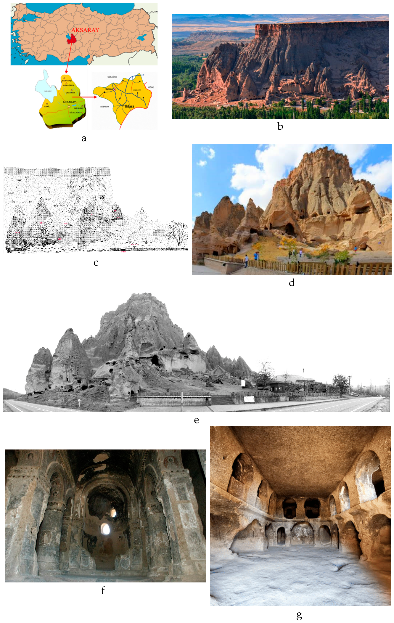
Figure 2.
Measured survey plans showing the spatial organisation of the Selime rock-cut complex at different elevations: (a) upper level; (b) middle level; (c) lower level.
Figure 2.
Measured survey plans showing the spatial organisation of the Selime rock-cut complex at different elevations: (a) upper level; (b) middle level; (c) lower level.
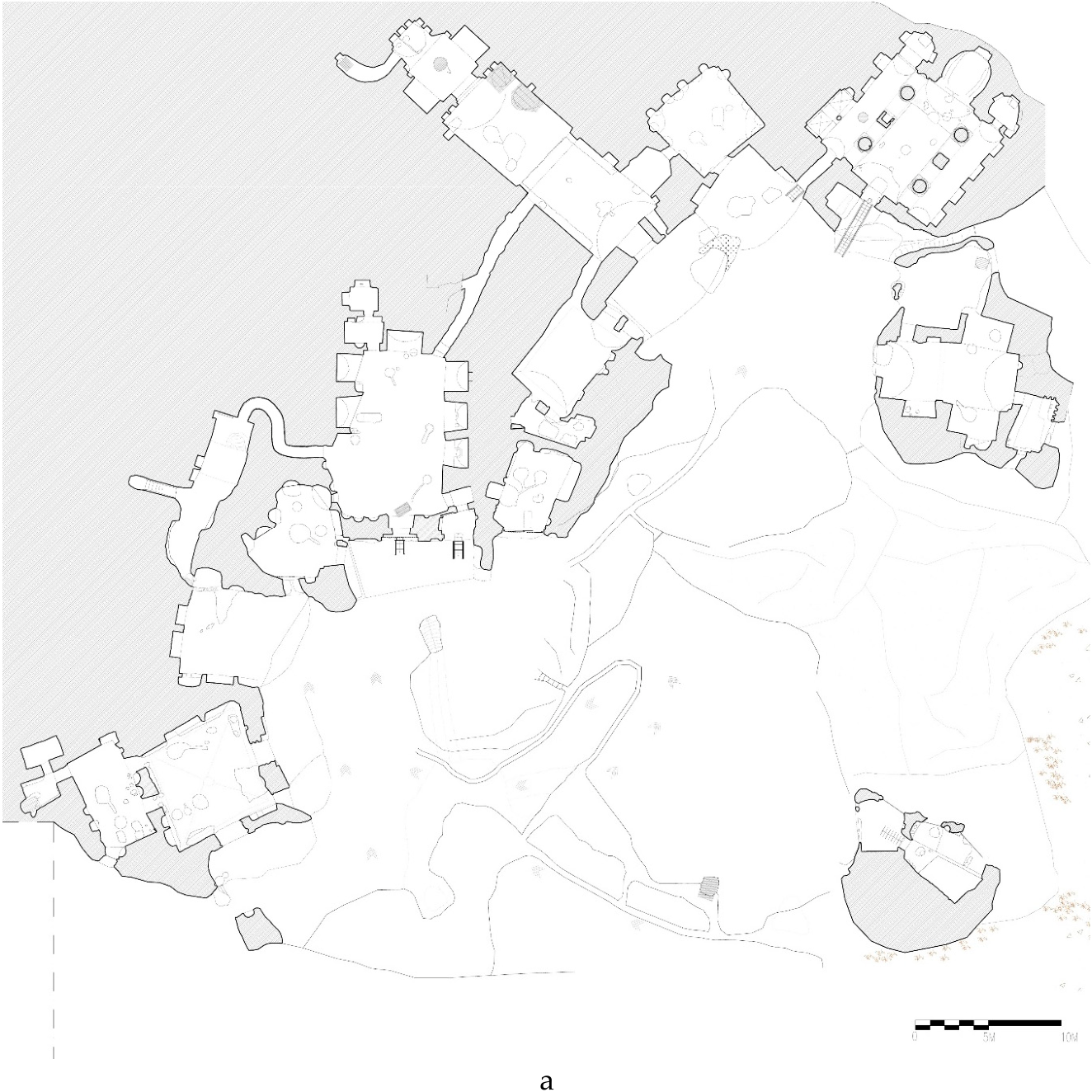
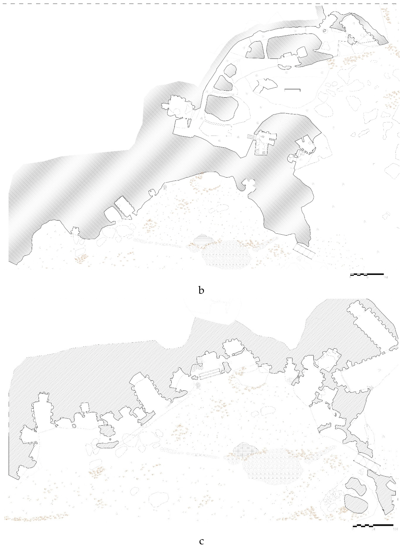
Figure 3.
Geodetic and architectural documentation system at the Selime complex: (a) local control network comprising P1–P4 control points and 54 stations; and (b) sample plans and sections produced from coordinate-based survey data. Source: Total Station Survey and Drawing Archive.
Figure 3.
Geodetic and architectural documentation system at the Selime complex: (a) local control network comprising P1–P4 control points and 54 stations; and (b) sample plans and sections produced from coordinate-based survey data. Source: Total Station Survey and Drawing Archive.
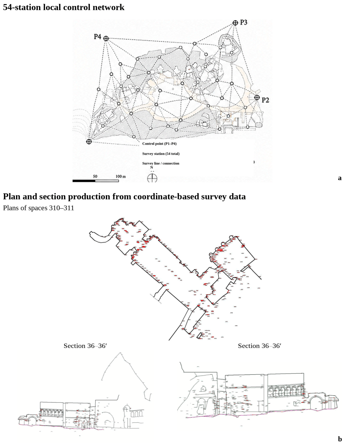
Figure 4.
Four examples from documentation to historical interpretation: (a) stable fixtures, (b) kitchen and chimney system in spaces 204–205, (c) distinction between natural rock surface and worked space at the 212–213 boundary, and (d) hypothetical volume 325.
Figure 4.
Four examples from documentation to historical interpretation: (a) stable fixtures, (b) kitchen and chimney system in spaces 204–205, (c) distinction between natural rock surface and worked space at the 212–213 boundary, and (d) hypothetical volume 325.
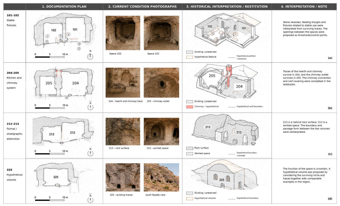
Figure 5.
Circulation and access arrangements at different elevations in the approved conservation and site-presentation project: (a) walking routes, the entrance-service area, and site-layout decisions at the lower level; (b) inter-spatial connections, walking surfaces, and local access arrangements at the upper level. Source: Restoration and Site-Planning Project.
Figure 5.
Circulation and access arrangements at different elevations in the approved conservation and site-presentation project: (a) walking routes, the entrance-service area, and site-layout decisions at the lower level; (b) inter-spatial connections, walking surfaces, and local access arrangements at the upper level. Source: Restoration and Site-Planning Project.
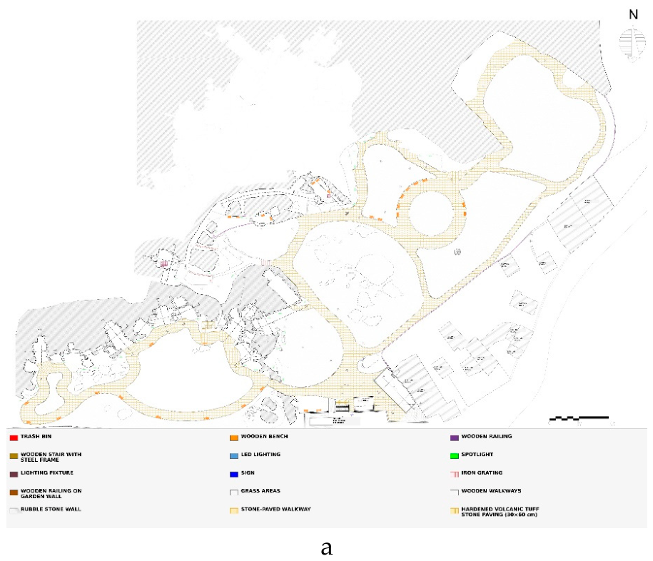
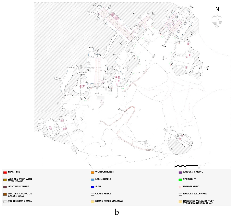
Figure 6.
Timber walkway system and interior passage solutions in the approved project: (a) partial plan showing the spatial layout of the timber walkway; (b) plan detail of the interior timber walkway and steps; (c) partial section showing the timber platform, railing, and changes in level. Source: Restoration and Site-Planning Drawings.
Figure 6.
Timber walkway system and interior passage solutions in the approved project: (a) partial plan showing the spatial layout of the timber walkway; (b) plan detail of the interior timber walkway and steps; (c) partial section showing the timber platform, railing, and changes in level. Source: Restoration and Site-Planning Drawings.
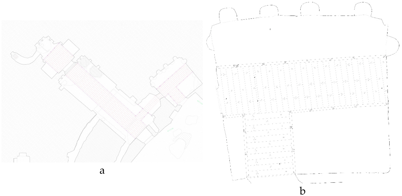
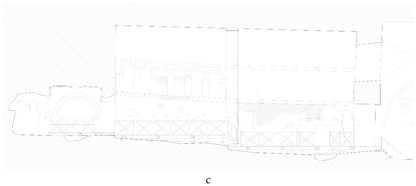
Figure 7.
Current condition of Selime on 19 July 2026: (a) entrance and commercial surroundings along the road frontage; (b) short timber steps; (c) local railings and passages at the upper levels; (d) general view showing the largely unchanged natural topography.
Figure 7.
Current condition of Selime on 19 July 2026: (a) entrance and commercial surroundings along the road frontage; (b) short timber steps; (c) local railings and passages at the upper levels; (d) general view showing the largely unchanged natural topography.
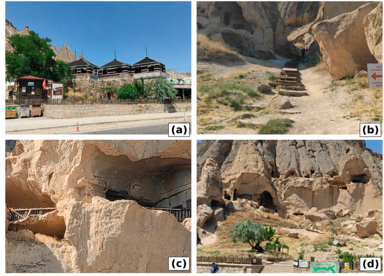
Figure 8.
Two-track reactivation protocol for approved conservation projects pending implementation: technical status is determined through H–R–O; implementation traceability is recorded separately through U; current action is selected by reading technical status and U together; and the results are linked to a cycle of implementation, maintenance, monitoring, and data updating.
Figure 8.
Two-track reactivation protocol for approved conservation projects pending implementation: technical status is determined through H–R–O; implementation traceability is recorded separately through U; current action is selected by reading technical status and U together; and the results are linked to a cycle of implementation, maintenance, monitoring, and data updating.
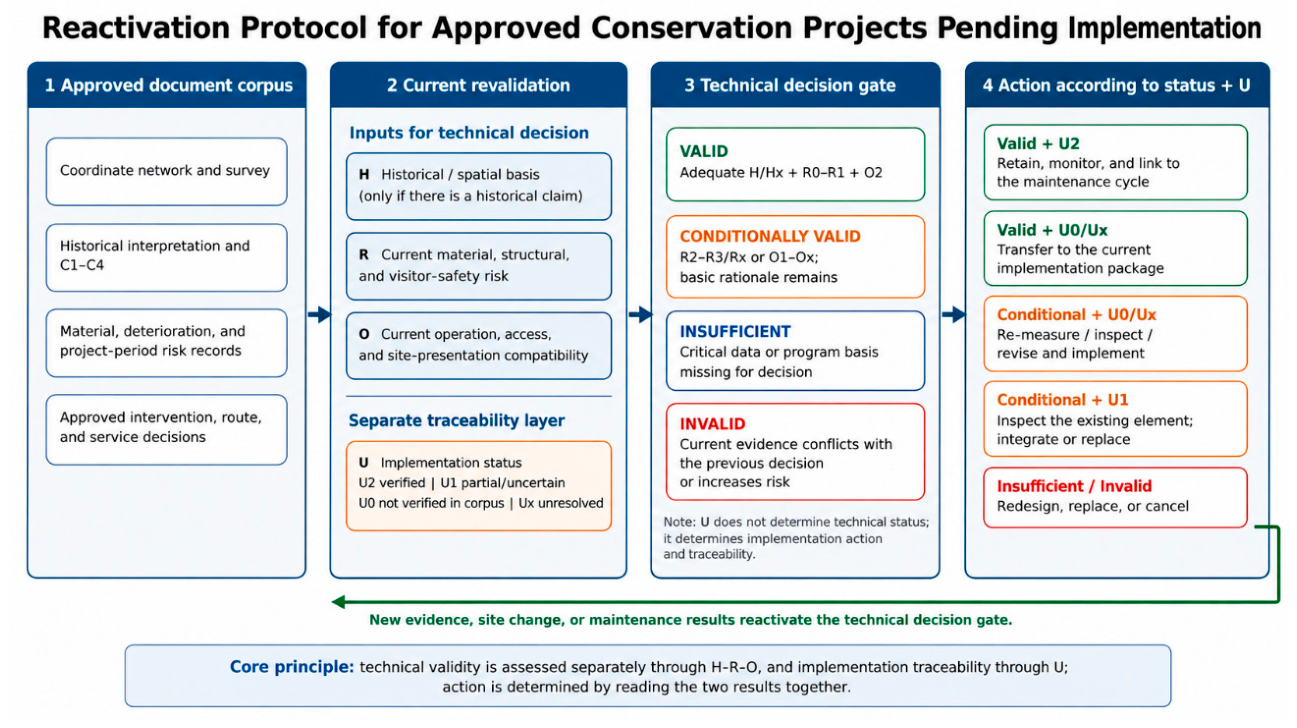
Table 1.
Institutional chronology of the Selime project process.
| Date | Stage | Main evidence | Function in the study |
|---|---|---|---|
| 18.09–16.10.2012 | Tender, contract, and site handover | Administrative files | Start of documentation and project preparation |
| 2012–26.10.2013 | Field survey and preparation of project documents | Survey report, drawings, and project reports | Production of architectural records and conservation decisions |
| September–10.10.2014 | Conservation Board approval and final acceptance of the project service | Board decision and final progress payment | Approved conservation and site-presentation scheme |
| After 2014 | Construction phase not verified within the documentary corpus examined | Administrative file records and the author’s professional knowledge | Unresolved implementation traceability in external institutional records (Ux) |
| 19.07.2026 | Limited visual survey | Six photographs and one video | Preliminary comparison of approved components with the available current images |
Table 2.
Geodetic and architectural documentation workflow.
| Stage | Implementation | Control method | Main output |
|---|---|---|---|
| Preliminary survey and levelling | Identification of sightlines, zero elevation, and the three main levels | General site inspection, photographs, and comparison with earlier plans | Survey strategy and elevation system |
| Station network | P1 main point, P2–P4 level controls, and a total of 54 stations | Stations linked by backsighting and common points | Coordinate-based field network |
| Space and façade survey | Connection of 52 space entrances, interior surfaces, and façades to the main system | Plan/section sketches and increased point density | Plan, section, and elevation geometry |
| Detail measurement | Stairs, niches, mouldings, openings, and floor irregularities | Laser distance meter and steel tape | Architectural details |
| Daily verification | Transfer of data to computer on the same day | Re-measurement of inconsistencies on site the following day | Corrected and interconnected drawing set |
Table 3.
Relationship between the main deterioration and risk groups and the corresponding project interventions.
Table 3.
Relationship between the main deterioration and risk groups and the corresponding project interventions.
| Deterioration / risk group | Main field indicators | Example areas | Project response |
|---|---|---|---|
| Surface and material deterioration | Darkening, flaking, loss of plaster/joints, fallen fragments | Lower, middle, and upper-level spaces; 121, 205, 207, 301, 309, 310, 313, 319 | Controlled cleaning, compatible plaster/mortar, loss and joint infill; specialist conservation report for frescoes |
| Water and moisture | Rainwater ingress, wet ceilings, thinning and decay | 107, 119, 201, 211, 218, 220, 224, 229–231, 301, 311, 318–319 | Surface drainage, control of openings, prevention of water ingress, and compatible infill |
| Cracking and layer separation | Open joints, secondary cracks, separated tuff layers | 112–115, 120–122, 210, 216–217, 226, 301, 305, 321–322 | Mortar infill, stainless-steel stitching, mini-bolts, and crack-gauge monitoring |
| Structural instability | Suspended blocks, thinned columns, unstable arches/vaults, and detachment | 102–103, 107–110, 117–118, 216–217, 225, 233, 302, 309, 311, 319 | Removable steel props/bracing, steel arch supports, local stone infill, and structural wall repair |
| Circulation and fall hazards | Floor voids, narrow slopes, thin rock floors, loose blocks at upper elevations | 201, 207, 212, 217–221, 226, 305, 310–313, 405–406, and the upper Kızılkaya area | Gratings, platforms, railings, selective closure, route modification, and upper-slope safety measures |
Table 4.
Comparison between the approved conservation and site-presentation project and the limited visual verification of 19 July 2026.
Table 4.
Comparison between the approved conservation and site-presentation project and the limited visual verification of 19 July 2026.
| Component | Approved project | Observed in the limited visual survey of 19 July 2026 | Preliminary assessment |
|---|---|---|---|
| Entrance and services | Reception arrangement combining security, information, rest areas, café, and toilets | Small booth, limited signage, and commercial surroundings | The approved service system could not be verified in the available images; broader field evidence and administrative records are required. |
| Circulation | Continuous three-level route, stairs, platforms, and interior passages | Short steps and some local passages | The integrated route could not be verified in the available images; other route sections are outside the image coverage. |
| Thresholds and safety | Gratings, selective closure, and space-specific railings | Local railings at some risk points | A localised safety measure was verified, but no contract-location-detail link to the approved project could be established. |
| Material and structure | Mortar repair, stitching, bolting, infill, structural support, and implementation monitoring | Available images are not suitable for detailed technical assessment | Outside the effective scope of the visual evidence; a new material and structural condition survey is required. |
| Maintenance and monitoring | Post-implementation condition recording and periodic monitoring | No record of cyclical maintenance was identified in the available corpus | No conclusion can be reached without examining external administrative and maintenance records. |
Disclaimer/Publisher’s Note: The statements, opinions and data contained in all publications are solely those of the individual author(s) and contributor(s) and not of MDPI and/or the editor(s). MDPI and/or the editor(s) disclaim responsibility for any injury to people or property resulting from any ideas, methods, instructions or products referred to in the content. |
© 2026 by the authors. Licensee MDPI, Basel, Switzerland. This article is an open access article distributed under the terms and conditions of the Creative Commons Attribution (CC BY) license (http://creativecommons.org/licenses/by/4.0/).
Copyright: This open access article is published under a Creative Commons CC BY 4.0 license, which permit the free download, distribution, and reuse, provided that the author and preprint are cited in any reuse.