

Submitted:
21 August 2026
Posted:
24 August 2026
You are already at the latest version
Abstract
As the core interception component of flexible rockfall barriers, the accurate characterization of the mechanical behavior of metal ring nets is essential for the safety assessment of the whole system. To overcome the limitations of existing computational models in reflecting the large-deformation states of the nets and the activation of energy dissipators, systematic uniaxial tension tests and puncture tests were first carried out on five specifications of ring nets (R8 to R19, 30 specimens in total). The results reveal a two-stage deformation feature (an initial low-force tensioning stage followed by a stiffness-hardening rapid-rise stage) and a parallel-superposition load-carrying mechanism under both loading cases. The experimental data were then normalized by dividing the force by the number of steel wires and non-dimensionalizing the dis-placement, on the basis of which a unified piecewise two-stage constitutive model, consisting of a linear tensioning segment and a power-hardening segment, was estab-lished to describe the response up to the peak point; the tensile and puncture cases share the same model form and are distinguished only by different parameters (fitting coefficient of determination R2 not lower than 0.97, with mean values of 0.98 and 0.983, respectively). A full-scale numerical model of the overall structure was subsequently established using LS-DYNA, in which the two side spans adopt the tensile constitutive model and the middle impact span adopts the puncture constitutive model. The model was verified against a 1500 kJ full-scale impact test. The computed time histories of the support-rope forces, the activation states of the energy dissipators (pressure-relief rings), the maximum interception deformation (computed 8.23 m versus measured 8.8 m, with a relative error of about 6.5%) and the energy-dissipation distribution of the pressure-relief rings (average relative error of about 5.2%) all agreed well with the experimental results. The proposed two-stage computational model can therefore accurately reflect the force and deformation states of the ring nets in the actual structure and correctly describe the transmission of the impact force and the activation of the energy dissipators, providing a reliable theoretical basis for the refined design of flexible rockfall barriers.
Keywords:
flexible rockfall barrier
; metal ring net
; two-stage computational model
; tensile and puncture tests
; full-scale impact test
; energy dissipation
1. Introduction
Flexible rockfall barriers are widely applied in the protection of rockfalls, slope debris flows, gully debris flows, and tunnel rockbursts, dissipating the enormous impact kinetic energy at the instant of interception through their flexible large-deformation energy dissipation mechanism [1,2,3]. The flexible metal net is the interception member that directly sustains the impact in the structure; it fully slides while undergoing large deformation, activating the energy dissipators to deform and dissipate energy, and provides more than 70% of the overall structural deformation, being one of the core members of the structure, among which the metal ring net is the most widely used (Figure 1). The metal ring net is fabricated by winding high-strength steel wires into rings, which are interconnected by a certain interlocking pattern to form the net panel; under impact it undergoes adaptive deformation and sliding, exhibiting an extremely high deformation capacity. However, the loose configuration and adaptive deformation also give rise to pronounced multi-flexible-body nonlinear dynamic characteristics and a non-uniform force-flow distribution, so that the accurate calculation of its mechanical behavior still faces many challenges [4].
The research on the mechanical models of ring nets has evolved from simple to complex. Early studies were mostly based on linear elastic theory, simplifying the net into a homogeneous material or discrete elements; for example, the zoned equivalent model proposed in Ref. [7], which combined ring tension tests with numerical simulation to establish the load-displacement relationship of the net under typical deformation states. In recent years, scholars have gradually introduced nonlinear mechanical theories to improve the model accuracy [9,10,11]; Ref. [8] revealed the three-stage working characteristics of ring nets through puncture tests and proposed an analytical method for the tensile deformation. Studies on tension and puncture tests have also been deepened progressively, providing data support for the mechanical modeling [12,13,14,15,16]. Nevertheless, the existing models still have limitations in comprehensively considering both the deformation of the net itself and the activation degree of the energy dissipators.
A review of the existing studies shows that current theoretical studies and numerical simulations mostly simplify the ring net into an isotropic continuum membrane or an orthogonal bar system to reduce the computational complexity. However, such over-simplification can hardly reflect the funnel-shaped deformation mechanism of the net under localized impact, nor accurately simulate its large-deformation behavior, resulting in the impact load failing to be effectively transmitted to the ends of the support ropes [22,23]. Related studies indicate that the energy dissipators undertake more than 50% of the energy dissipation of the system and are the most critical energy-dissipating components of the protection system [20,21]. When the deformation capacity of the net model is limited, the support ropes are blocked by friction at the steel posts and the tension transmitted to the energy dissipators is insufficient, so that the energy dissipators fail to activate, and in extreme cases this even causes systemic failure of the support ropes due to a sudden tension surge (peak exceeding 360 kN). Moreover, the ring net exhibits evident staged characteristics (elastic and hardening stages) during loading, and the mechanical responses of nets of different specifications differ greatly; the existing models can hardly take into account both the deformation state of the net itself and the activation degree of the energy dissipators.
In view of the above problems, this paper aims to establish an improved two-stage computational model that can more realistically reflect the mechanical behavior of ring nets and their synergistic working mechanism with energy dissipators. First, systematic uniaxial tension and puncture tests were carried out on ring nets of five specifications from R8 to R19 to obtain their mechanical response parameters under different loading states and to reveal the deformation mechanism and failure modes. Then, based on the test data, an improved multi-stage computational model accounting for material nonlinearity and structural geometric characteristics was constructed, focusing on the description of the stiffness hardening of the net in the large-deformation stage. Finally, the actual rockfall impact condition was simulated by a full-scale impact test, and the measured net deformation and energy-dissipator activation data were compared with the model predictions, providing a reliable theoretical basis for the refined design and safety assessment of flexible protection nets.
2. Uniaxial Tension and Puncture Test Study of Metal Ring Nets
2.1. Test Scheme Design
To comprehensively obtain the mechanical properties of the metal ring net, this study formulated a test scheme covering multiple loading states and net specifications, including uniaxial tension tests and puncture tests [14,15]. The uniaxial tension test aims to reveal the mechanical behavior of the ring net under axial loading, while the puncture test focuses on the penetration resistance and failure modes of the ring net under localized impact loading, with the specimen specifications covering the commonly used range. The systematically obtained mechanical properties provide basic data for establishing the subsequent improved computational model. The test instruments are shown in Figure 2.
Considering the specification range of commonly used metal ring nets, practical engineering applications, and the objective requirement of the theoretical analysis for data volume, five specifications of ring-net specimens were selected (Table 1), and three specimens of each specification were subjected to the tension and puncture tests, respectively.
The uniaxial tension tests were carried out using a commercial hydraulic tension testing machine with self-made tension fixtures, with a maximum loading capacity of 1000 kN, a loading rate of 6–10 mm/min, a displacement measurement accuracy of ±0.5 μm, and force measured by a high-precision load cell with an accuracy of ±0.02% F.S. [16].
The puncture tests were likewise carried out using a commercial hydraulic testing machine with a self-made puncture test frame, equipped with a dedicated spherical puncture head (spherical radius 1200 mm, maximum projection diameter 1000 mm) with a 50 mm chamfer at the edge of the head to avoid the local sharp edges cutting the members; the maximum loading capacity was 1500 kN, and the loading rate and accuracy were the same as those of the tension testing machine.
2.2. Uniaxial Tension Test
During the test, the prepared ring-net specimen was installed in the fixtures of the testing machine to ensure natural spreading. The specimen was fixed in a four-side slidable manner, and the top was uniformly tensioned in-plane through a load-sharing beam. After zeroing the instruments, loading was performed in displacement control mode at 10 mm/min until the specimen fractured, and the load and displacement data were recorded in real time by the built-in data acquisition system. The tension test process is shown in Figure 3.
The force-displacement relationships of the specimens of all specifications are shown in Figure 4. All curves present a clear two-stage relationship: first, large deformation in tension dominates and the load increases extremely slowly, with the specimen gradually tightening; in the second stage, the force increases sharply with displacement in a curve-rise manner. The mean breaking forces and peak displacements of the specimens are listed in Table 2; the breaking force increases with increasing net-ring specification (i.e., the number of wound strands), while the peak displacements of nets of different specifications vary within a small range. The summarized results are shown in Figure 5.
2.3. Puncture Test
During the test, the surrounding rings of the specimen were fixed in the test frame by fixtures with the edge rings slidable, and the puncture head was aligned with the exact center of the specimen. After zeroing, loading was performed in displacement control mode at 10 mm/min until the specimen fractured, and the load and displacement data were recorded in real time. The puncture test process is shown in Figure 6 [15].
The force-displacement results of the specimens of all specifications are shown in Figure 7. Under the puncture loading state, the curves are nearly identical to those of the tension tests, also exhibiting the two-stage characteristics of initial tensioning followed by a sharp increase. The mean breaking forces and peak displacements of the specimens are listed in Table 3; the breaking force increases with increasing specification while the peak displacement varies within a small range. As the initial dimensions of the puncture specimens are easier to control, the curves of specimens of the same specification are closer to each other. The summarized results are shown in Figure 8.
2.4. Summary of the Tests
Through the uniaxial tension and puncture tests, the force-displacement curves, breaking forces, and peak displacements of 30 specimens of five specifications were systematically obtained. The results show that the specification has a significant influence on the breaking force, while the peak displacements of specimens of different specifications under the same loading state are relatively close [24].
Whether in the tension or puncture tests, the force-displacement curves exhibit the same shape, both showing the two-stage characteristics of initial tensioning followed by a sharp increase, which lays a solid foundation for establishing a unified net model.
3. Establishment of the Improved Two-Stage Computational Model
Observations of the full-scale impact tests of flexible rockfall barriers show that in the impact span, the net suffers out-of-plane rockfall impact and its overall deformation and loading state are close to those of the puncture test; in the side spans, the net slides and stretches along the structural length driven by the impact-span net, and its loading state is close to that of the tension test. This is also the reason why tension and puncture tests of specimens of the same specification were carried out simultaneously [25,26].
The test results show that the net presents apparently similar two-stage deformation characteristics in both the tension and puncture processes. In the early stage of loading, the net mainly experiences gradual contacting from the initially “loose and soft” state, and the displacement-force relationship basically follows a linear law with slow and extremely small load growth; when the elongation further increases, the rings undergo a state change “from an arc to a straight line”, and the displacement-force curve shows a sharp increase of force with displacement.
The ring net undertakes two main loading cases in flexible rockfall protection systems: the tension case reflects the force-displacement response of the net under in-plane tension, and the puncture case reflects the bearing capacity of the net under concentrated loading (rockfall impact). Although the loading modes differ, both are formed by winding multiple steel wires into rings and carrying load in parallel, so their mechanical mechanisms are consistent [14]. Accordingly, this chapter adopts a unified normalization method and modeling procedure for the two cases to establish a unified-format piecewise constitutive model, describing the two loading states by different material parameters.
3.1. Normalization of the Test Results
The ring net is fabricated by winding several high-strength steel wires into rings; the specifications R8–R19 indicate that the rings are wound from 8 to 19 steel wires, respectively. To eliminate the influence of the number of steel wires on the force dimension, make the test results of different specifications comparable, and facilitate the establishment of a unified mechanical model, the force-displacement curves obtained from the tension tests were first normalized: the force was divided by the number of wound steel wires n and the displacement by the initial gauge length of the ring net of 1100 mm, i.e., [24]
For the tension case, the specimen is loaded in-plane in tension, and the normalized displacement is taken as the ratio of the measured displacement to the initial gauge length, i.e.,
For the puncture case, the specimen is 3.2 m × 3.2 m, fixed on four sides and loaded at the center; the penetration depth δ at the loading point is converted through a geometric relationship into a dimensionless relative elongation “from the loading end to the edge of the specimen”, i.e.,
where Δt and δ are the measured displacements of the tension and puncture cases (mm), respectively, and r = 1600 mm is the distance from the center to the fixed edge. A total of 15 tension curves and 15 puncture curves (three specimens for each of the five specifications) were all normalized uniformly.
3.2. Analysis of the Normalized Results
The normalized curves of both cases exhibit the typical two-stage form of “initial low-force tensioning segment—hardening rapid-rise segment—post-peak fracture”, with good consistency among specimens of the same group and obvious self-similar characteristics; Figure 9 shows the normalized curves of the tension and puncture cases. Fitting the total peak bearing capacity of each specification against the number of steel wires N gives, for the tension and puncture cases respectively [5]
The total bearing capacities of both cases are strongly linearly correlated with the number of steel wires N, with power-law fitting exponents of about 1.04 and 1.18, respectively, both close to or slightly larger than 1, indicating that the ring net follows the “parallel superposition” bearing mechanism in both tension and puncture: the steel wires share the load approximately in parallel, and each additional steel wire increases the total tension bearing capacity by about 35 kN and the unilateral oblique puncture bearing capacity by about 39 kN. The mean normalized peak forces are 32.5 kN for tension and 31.3 kN for the equivalent unilateral puncture value, both basically not varying significantly with N [24].
3.3. Unified Piecewise Constitutive Model
Since the normalized curves of the two cases are consistent in shape and self-similar, a unified-format piecewise constitutive model can be established, using a “linear tensioning segment + power-hardening segment” to describe the response up to the peak point [6]:
where k0 is the stiffness of the tensioning segment; χ1 is the displacement at the end of the tensioning segment and F1 = k0·χ1 is the force at the end of the tensioning segment; p is the power-hardening exponent; A = (Fp − F1)/(χp − χ1)p is the hardening coefficient determined by the continuity condition at the peak point (χp, Fp); χp and Fp are the peak displacement and peak force, respectively. The model contains five parameters (k0, p, χ1, χp, Fp), has exactly the same functional form for the tension and puncture cases, and differs only in the parameter values. The overall force-displacement model is
For the tension case, the 15 normalized tension curves were fitted separately by least squares according to Eq. (6); the coefficient of determination R2 of each specimen was not lower than 0.97, with a mean value of 0.98 [16]. Taking the mean parameter values, the unified parameters for the tension case are k0t = 8.75 kN, pt = 6.51, χ1t = 0.097, χpt = 0.313, Fpt = 32.54 kN, and further F1t = 0.852 kN and At = 6.93×10⁵.
For the puncture case, the 15 normalized puncture curves were fitted separately, and the mean R2 reached 0.983 [15]. Taking the mean parameter values, the unified parameters for the puncture case are k0p = 42.4 kN, pp = 5.78, χ1p = 0.026, χpp = 0.227, Fpp = 33.4 kN, and further F1p = 1.11 kN and Ap = 3.44×10⁵.
Accordingly, the tension and puncture cases adopt the same constitutive form and differ only in the parameters, as compared in Table 4.
It can be seen from Table 4 that the unilateral oblique peak force of the puncture case is comparable to that of the tension case (about 32–33 kN), but the tensioning stiffness of the puncture case is about 4.8 times that of the tension case, and the power-hardening exponent and peak displacement are smaller, reflecting the mechanical characteristics of more concentrated loading and faster deformation of the net under concentrated loading.
3.4. Model Verification
Figure 10 shows the comparison between the unified constitutive curve of the tension case and the predictions of the parallel-superposition model with the measurements, and Figure 11 shows the corresponding verification of the puncture case. It can be seen that the unified piecewise constitutive curves all pass through the center of the distribution of the normalized measured data of each specification, and the predicted and measured total force-displacement curves agree well before the peak, verifying the rationality and applicability of the unified model [9,27,28].
3.5. Summary of This Chapter
This chapter established a unified-format mechanical model for the tension and puncture cases of the ring net. The test data of the two cases were first normalized (force divided by the number of steel wires N, displacement non-dimensionalized according to the in-plane elongation and the geometric oblique length relationship, respectively), revealing that both cases follow the “parallel superposition” bearing mechanism; a unified piecewise constitutive model f̄(χ) was then established, describing the two loading states by the five parameters (k0, p, χ1, χp, Fp), and the force-displacement relationship for any specification with N steel wires is given by F(χ; N) = N·f̄(χ). The unified model is concise in form, clear in physical meaning, and of high fitting accuracy (R2 ≥ 0.98), with the differences between the puncture and tension cases quantitatively reflected by the parameters, providing a unified theoretical basis for the prediction of the mechanical properties and the engineering design of ring nets.
4. Verification of the Model
To verify the accuracy of the established mechanical model of the metal ring net, a full-scale impact test of the overall structure with 1500 kJ energy was carried out [3,17,19]. A comparative numerical simulation model was then established using the ring-net model established above, and the accuracy of the model was verified from several aspects, including the overall structural deformation, the internal forces of the main members, and the activation states of the structural energy dissipators.
4.1. Overview of the Full-Scale Impact Test
The test protection net was designed and installed according to the actual passive flexible protection system; the net body was suspended on the test wall and fixed to the anchor points by a cable system composed of support ropes and pressure-relief rings, and the impact energy was absorbed and intercepted jointly through the overall structural deformation, the tensioning of the support ropes, and the energy dissipation of the pressure-relief rings. The basic configuration parameters of the test protection net are listed in Table 5 [25].
A large-mass drop hammer was released in free fall along the vertical direction to impact the middle of the net face, with an impact energy of 1500 kJ and an impact velocity near the net of not less than 25 m/s. Force sensors were arranged near the anchor ends of the steel wire ropes to record the cable force time histories, and a high-speed camera was used to record the impact process of the net face. The full-scale impact test is shown in Figure 12.
4.2. Establishment of the Numerical Simulation Model
Based on the piecewise constitutive mechanical model of the metal ring net established above, an overall structural numerical simulation model corresponding to the full-scale impact test was established using the LS-DYNA explicit finite element software. The element types and constitutive behavior of the main members in the model are described as follows. The overall structural numerical simulation model is shown in Figure 13 [5,27].
The discretization of the ring-net element model is consistent with Ref. [26], except that the constitutive relationship adopts the above piecewise constitutive mechanical model. In modeling, nodes were first established at the inter-ring contact positions and at the centers of the rings, and four circular-section truss elements were established by connecting the nodes, so as to complete the equivalent discretization of the whole ring net in a head-to-tail manner. To ensure equal inertial effects after discretization, mass equivalence of the discrete elements must be maintained. Since the initial length of each equivalent element is the initial radius R of the ring and the material density remains unchanged after equivalence, the mass equality can be established by the equivalence of the volumes of the equivalent element and the original ring; the section radius of the equivalent truss element is thus obtained as [6]
where r is the radius of the steel wire and n is the number of wound rings.
To combine with the commonly used finite element calculation method, the force-displacement (P–δ) restoring force relationship of the ring needs to be converted into the material stress-strain relationship of the equivalent bar element; the equivalent strain and equivalent stress are, respectively,
where δ is the deformation of the ring and P is the tension of the ring. Accordingly, the equivalent computational models of ring nets of different specifications can be established according to the specific parameters of the rings.
Considering that the ring nets in different spans of the overall structure are in different loading states, the structure was divided by spans in modeling: the ring nets in the two side spans adopt the piecewise constitutive model calibrated for the tension case, and the ring nets in the middle span (impact span) adopt the piecewise constitutive model calibrated for the puncture case. In modeling, the normalized piecewise constitutive calibrated for the tension and puncture cases, respectively, was restored to the actual load-displacement relationship according to the geometric and material parameters of the rings, and then converted into the equivalent stress-strain relationship of the equivalent elements and assigned to each truss element; meanwhile, a one-dimensional slidable contact was used to simulate the slidable support between the ring net and the support ropes [25,26].
The support ropes and anchor ropes are high-strength steel wire ropes, established using cable elements that can simulate uniaxial tension, with the material taking the elastic modulus of the high-strength steel wire rope to reflect the tensioning process of the steel wire ropes [21,29].
The pressure-relief rings were simulated as combined energy-dissipating elements, and their activation process (reduction of the ring diameter and straightening of the round tube) was described by the three-stage working state of activation load, maximum tensile load, and maximum elongation; the computational model was established by converting the load-displacement relationship of a single pressure-relief ring into a stress-strain relationship, so as to reflect the activation and energy dissipation process of the pressure-relief rings [20,22,23,30,31].
The supporting structure was discretized according to the actual test configuration, and the relative sliding between the support ropes and the anchor points was simulated by corresponding sliding contacts, with the boundary conditions consistent with the test.
The impact condition was consistent with the test: the impact block was released in free fall along the vertical direction to impact the center of the middle span of the net face, applying 1500 kJ impact energy to the structure, and the nonlinear dynamic response of the structure was solved by explicit time integration.
4.3. Verification Results and Analysis
To verify the accuracy of the net mechanical model, the numerical results were compared with the full-scale test measurements from three aspects: the support-rope force time histories, the activation states of the pressure-relief rings, and the overall structural impact interception deformation [18].
As the cable force time histories finally obtained in the full-scale impact test were limited, this section only compares the force time histories of the upper and lower support ropes and the two inner upper anchor ropes of the impact span obtained from the test and the calculation. The results show that the calculated variation trend of the support-rope force with time is consistent with the measured curves, and the time and magnitude of the peak force agree well, with good overall consistency between the two, verifying that the ring-net mechanical model can accurately reflect the process of the impact load transmitted in the net and the resulting loading on the support ropes. The comparison of the cable force time histories is shown in Figure 14 [21,29].
In the test, the activation characteristic of the pressure-relief rings is manifested as an obvious reduction of the ring diameter and straightening of the round tube [32]. As shown in Table 6, the ranking of the energy dissipation of the pressure-relief rings of each member is consistent between the test and the numerical simulation, namely the lower support-rope pressure-relief rings (about 400 kJ) > the upper anchor-rope pressure-relief rings (about 375 kJ) > the upper support-rope pressure-relief rings (about 220 kJ), indicating that the model can correctly reflect the distribution of the impact energy among the energy-dissipating members. The average relative error of the energy dissipation of the three pressure-relief rings is about 5.2%, among which the errors of the upper anchor rope (1.7%) and the lower support rope (3.8%) are small and in good agreement; the error of the upper support-rope pressure-relief ring is the largest (about −10.0%), with the calculated value being low, which may be related to the simulation differences in the load-transfer path of the upper support rope and the activation sequence of the pressure-relief rings, and is still within the acceptable engineering error range. The activation states of the upper and lower support-rope pressure-relief rings and the comparison of the energy dissipation are shown in Figure 15 and Figure 16.
Comparing the maximum impact interception deformation of the protection net after impact (the maximum vertical displacement of the net face), the measured maximum interception deformation in the full-scale test was 8.8 m, and the calculated result of the numerical simulation was 8.23 m, with a relative error of about 6.5%, showing good agreement. The consistency of the maximum interception deformation indicates that the ring-net mechanical model can well reflect the force and deformation state of the overall structure under impact [18,33].
4.4. Summary of This Chapter
Through the comparison and verification of the 1500 kJ full-scale impact test and the LS-DYNA numerical simulation results based on the ring-net mechanical model, good consistency was achieved in the three aspects of the upper and lower support-rope force time histories, the activation states of the pressure-relief rings, and the maximum impact interception deformation of the overall structure. The verification results show that the established piecewise mechanical model of the metal ring net can well reflect the force and deformation state of the overall structure, accurately describe the transmission of the impact force in the ring net and the activation process of the energy dissipators (pressure-relief rings) in the actual structure, and can be used for the overall design and analysis of passive flexible protection systems.
5. Conclusions
Through systematic uniaxial tension and puncture tests, normalization analysis and modeling, as well as full-scale impact test and numerical simulation verification, this paper established a two-stage computational model that can more realistically reflect the mechanical behavior of the metal ring net and its synergistic working mechanism with the energy dissipators, and the following main conclusions are drawn.
(1) The uniaxial tension and puncture tests of 30 ring-net specimens of five specifications from R8 to R19 show that the force-displacement curves of the net under both loading cases present the two-stage deformation characteristics of “initial tensioning—sharp increase”, the breaking force increases approximately linearly with the number of steel wires N following the “parallel superposition” bearing mechanism, and the peak displacement remains relatively stable.
(2) After the normalization of the test data (force divided by the number of steel wires N, displacement non-dimensionalized according to the in-plane elongation and the geometric oblique length relationship, respectively), the normalized curves of nets of different specifications under the two loading cases both exhibit obvious self-similar characteristics. On this basis, a unified-format piecewise constitutive mechanical model was established, using a “linear tensioning segment + power-hardening segment” to describe the whole process of the net loading up to the peak point, with the tension and puncture cases adopting the same constitutive form and distinguished only by different parameters. The coefficient of determination R2 of each specimen was not lower than 0.97 (with mean values of 0.98 for tension and 0.983 for puncture), and the model can accurately describe the force and deformation characteristics of ring nets of different specifications.
(3) Based on the established net mechanical model, an overall structural numerical simulation model corresponding to the 1500 kJ full-scale impact test was established using LS-DYNA, in which the two side spans adopt the tension-case constitutive and the middle impact span adopts the puncture-case constitutive. Compared with the full-scale test results, good consistency was achieved in the upper and lower support-rope force time histories, the activation states of the pressure-relief rings, the maximum impact interception deformation of the overall structure (measured 8.8 m, calculated 8.23 m, relative error about 6.5%), and the energy-dissipation distribution of the pressure-relief rings (average relative error about 5.2%), verifying the accuracy and applicability of the net mechanical model.
(4) The verification results show that the established two-stage computational model can accurately reflect the force and deformation responses of the ring net under in-plane tension and out-of-plane concentrated impact in the actual structure, correctly describe the transmission of the impact force in the net and the activation and energy dissipation process of the energy dissipators (pressure-relief rings), and can be used for the refined design, energy-distribution assessment, and safety analysis of flexible rockfall protection systems.
Data Availability Statement
The original contributions presented in this study are included in the article. Further inquiries can be directed to the corresponding author.
References
- Ge, Z.; Liu, H. Numerical investigation on the dynamic response of rockfall impacts on flexible barrier under seismic loading[J]. Nat. Hazards 2022, 115(2), 1213–1234. [Google Scholar] [CrossRef]
- Li, X.; Zhao, J.; Kwan, J. S. H. Assessing debris flow impact on flexible ring net barrier: a coupled CFD-DEM study[J]. Comput. Geotech. 2020, 128, 103850. [Google Scholar] [CrossRef]
- Zhao, L.; Zhang, L.; Yu, Z.; et al. A case study on the energy capacity of a flexible rockfall barrier in resisting landslide debris[J]. Forests 2022, 13(9), 1384. [Google Scholar] [CrossRef]
- Zhu, Z. H.; Yin, J. H.; Qin, J. Q.; Tan, D. Y. A new discrete element model for simulating a flexible ring net barrier under rockfall impact comparing with large-scale physical model test data[J]. Comput. Geotech. 2019, 116, 103208. [Google Scholar] [CrossRef]
- Jin, Y.; Yu, Z.; Guo, L.; et al. An efficient hybrid simulation method to quantitatively analyze the flexible wire-ring net rockfall protection systems[J]. Int. J. Numer. Anal. Methods Geomech. 2025, 50(1), 38–52. [Google Scholar] [CrossRef]
- Zhu, Z. H.; Yin, J. H.; Ouyang, C. J.; Tan, D. Y.; Qin, J. Q. Modeling a flexible ring net with the discrete element method[J]. J. Eng. Mech. 2020, 146(2), 04019120. [Google Scholar] [CrossRef]
- Nicot, F.; Cambou, B.; Mazzoleni, G. From a constitutive modelling of metallic rings to the design of rockfall restraining nets[J]. Int. J. Numer. Anal. Methods Geomech. 2001, 25(1), 49–70. [Google Scholar] [CrossRef]
- Volkwein, A.; Schellenberg, K.; Labiouse, V.; et al. Rockfall characterisation and structural protection: a review[J]. Nat. Hazards Earth Syst. Sci. 2011, 11(9), 2617–2651. [Google Scholar] [CrossRef]
- Coulibaly, J. B.; Chanut, M. A.; Lambert, S.; Nicot, F. Toward a generic computational approach for flexible rockfall barrier modeling[J]. Rock. Mech. Rock. Eng. 2019, 52(11), 4475–4496. [Google Scholar] [CrossRef]
- Gentilini, C.; Gottardi, G.; Govoni, L.; Mentani, A.; Ubertini, F. Design of falling rock protection barriers using numerical models[J]. Eng. Struct. 2013, 50, 96–106. [Google Scholar] [CrossRef]
- Sautter, K.; Hofmann, H.; Wendeler, C.; et al. Advanced modeling and simulation of rockfall attenuator barriers via partitioned DEM-FEM coupling[J]. Front. Built Environ. 2021, 7, 659382. [Google Scholar] [CrossRef]
- Liu, C.; Tian, S.; Xu, C.; Yang, J. Study on mechanical properties and dissipation capacity of ring net in passive rockfall barriers[J]. In Natural Hazards and Earth System Sciences Discussions; 2018. [Google Scholar] [CrossRef]
- Qi, X.; Deng, Q.; Zhao, L.; et al. Equivalent relationship of the mechanical behavior of ring nets under static punching and dynamic impact conditions[J]. Buildings 2023, 13(3), 588. [Google Scholar] [CrossRef]
- Trad, A.; Limam, A. Load testing and simulation of asymmetric cable-net used for flexible rockfall protection barriers[J]. Eur. J. Environ. Civ. Eng. 2022, 26(15), 7685–7702. [Google Scholar] [CrossRef]
- Guo, L. P.; Yu, Z. X.; Luo, L. R.; Qi, X.; Zhao, S. C. Analytical method for the puncture mechanical behavior of ring nets based on force-flow equivalence[J]. Eng. Mech. 2020, 37(5), 129–139. [Google Scholar] [CrossRef]
- Jin, Y. T.; Yu, Z. X.; Guo, L. P.; Luo, L. R.; Zhang, L. J.; Liao, L. X. Tension-bending stiffness coordination model for strand ring nets in flexible rockfall protection systems[J]. Chin. J. Rock. Mech. Eng. 2023, 42(3), 698–707. Available online: https://m.zhangqiaokeyan.com/academic-journal-cn_chinese-journal-rock-mechanics-engineering_thesis/02012104505347.html.
- Yu, Z.; Zhao, L.; Guo, L.; et al. Full-scale impact test and numerical simulation of a new-type resilient rock-shed flexible buffer structure[J]. Shock Vib. 2019, 2019, 7934696. [Google Scholar] [CrossRef]
- Koo, R. C. H.; Kwan, J. S. H.; Lam, C.; et al. Dynamic response of flexible rockfall barriers under different loading geometries[J]. Landslides 2017, 14(3), 905–916. [Google Scholar] [CrossRef]
- Liao, L.; Yu, Z.; Liu, D.; et al. Design method and impact response of energy-consuming high-fall flexible protection system for construction[J]. Buildings 2023, 13(6), 1376. [Google Scholar] [CrossRef]
- Pimpinella, F.; Marchelli, M.; De Biagi, V. A weight-based efficiency measure for energy dissipating devices for flexible rockfall barriers[J]. Int. J. Prot. Struct. 2024, 16(4), 956–980. [Google Scholar] [CrossRef]
- Zhao, L.; Zou, D. F.; Qi, X.; Ma, P. C. Load transfer mechanisms in support ropes of flexible rockfall barriers: geometrical relationships and transmission attenuation[J]. Int. J. Prot. Struct. 2025, 17(3), 834–854. [Google Scholar] [CrossRef]
- Castanon-Jano, L.; Blanco-Fernandez, E.; Castro-Fresno, D. Design of a new energy dissipating device and verification for use in rockfall protection barriers[J]. Eng. Struct. 2019, 199, 109633. [Google Scholar] [CrossRef]
- He, Z. H.; Yu, Z. X.; Liao, L. X.; Lyu, Y. F.; Tian, Y. D. Research on data-driven intelligent design method for energy dissipator of flexible protection systems[J]. Adv. Steel Constr. 2024, 20(4). [Google Scholar] [CrossRef]
- Guo, L.; Yu, Z.; Jin, Y.; Liao, L.; Luo, L. An analytical method for evaluating the deflection and load-bearing and energy absorption capacity of rockfall ring nets considering multifactor influence[J]. Adv. Steel Constr. 2022, 18(3). [Google Scholar] [CrossRef]
- Zhao, Y. N.; Yu, Z. X.; Zhao, S. C. Zoned equivalent model of ring interception nets in flexible protection systems[J]. J. Southwest Jiaotong Univ. 2019, 54(4), 808–815. [Google Scholar] [CrossRef]
- Zhao, Y. N.; Yu, Z. X.; Zhao, S. C. Numerical calculation method for multi-span flexible passive ring-net barrier structures[J]. J. Vib. Shock 2019, 38(17), 211–219. Available online: https://jvs.sjtu.edu.cn/CN/abstract/abstract8794.shtml.
- Qi, X.; Yu, Z.; Zhao, L.; Xu, H.; Zhao, S. A new numerical modelling approach for flexible rockfall protection barriers based on failure modes[J]. Adv. Steel Constr. 2018, 14(3), 479–495. [Google Scholar] [CrossRef]
- Xia, C.; Zhang, Z.; Liu, C.; Zhang, H.; Tian, S. Study on numerical model and dynamic response of ring net in flexible rockfall barriers[J]. Sustainability 2022, 14(8), 4406. [Google Scholar] [CrossRef]
- Qi, X.; Zhao, L.; Meng, Q. C. Prediction method for the tension force of support ropes in flexible rockfall barriers based on full-scale experiments and numerical analysis[J]. Sci. Rep. 2024, 14, 9969. [Google Scholar] [CrossRef]
- Castanon-Jano, L.; Blanco-Fernandez, E.; Castro-Fresno, D.; Ballester-Muñoz, F. Energy dissipating devices in falling rock protection barriers[J]. Rock. Mech. Rock. Eng. 2017, 50(3), 603–619. [Google Scholar] [CrossRef]
- del Coz Díaz, J. J.; García Nieto, P. J.; Castro-Fresno, D.; Rodríguez-Hernández, J. Nonlinear explicit analysis and study of the behaviour of a new ring-type brake energy dissipator by FEM and experimental comparison[J]. Appl. Math. Comput. 2010, 216(5), 1571–1582. [Google Scholar] [CrossRef]
- Guo, L.; He, S.; Yu, Z.; Jin, Y. Damage assessment of ring nets in flexible barriers subjected to consecutive rockfall impacts[J]. Can. Geotech. J. 2025, 62, 1–21. [Google Scholar] [CrossRef]
- Lambert, S.; Toe, D.; Mentani, A.; Bourrier, F. A meta-model-based procedure for quantifying the on-site efficiency of rockfall barriers[J]. Rock. Mech. Rock. Eng. 2021, 54(2), 487–500. [Google Scholar] [CrossRef]
Figure 1.
Schematic of structural impact interception.

Figure 2.
Test instruments.
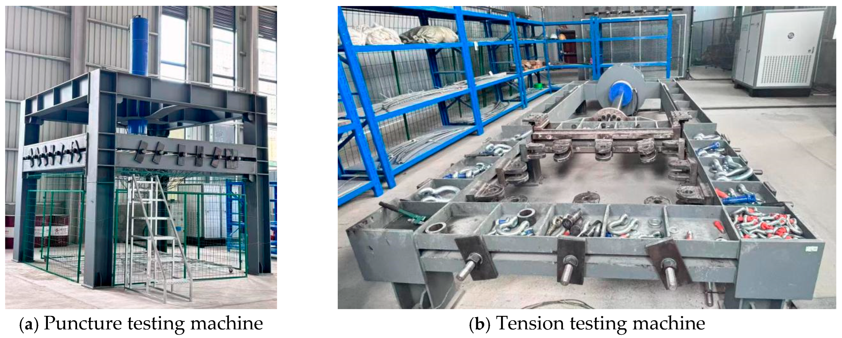
Figure 3.
Tension test.
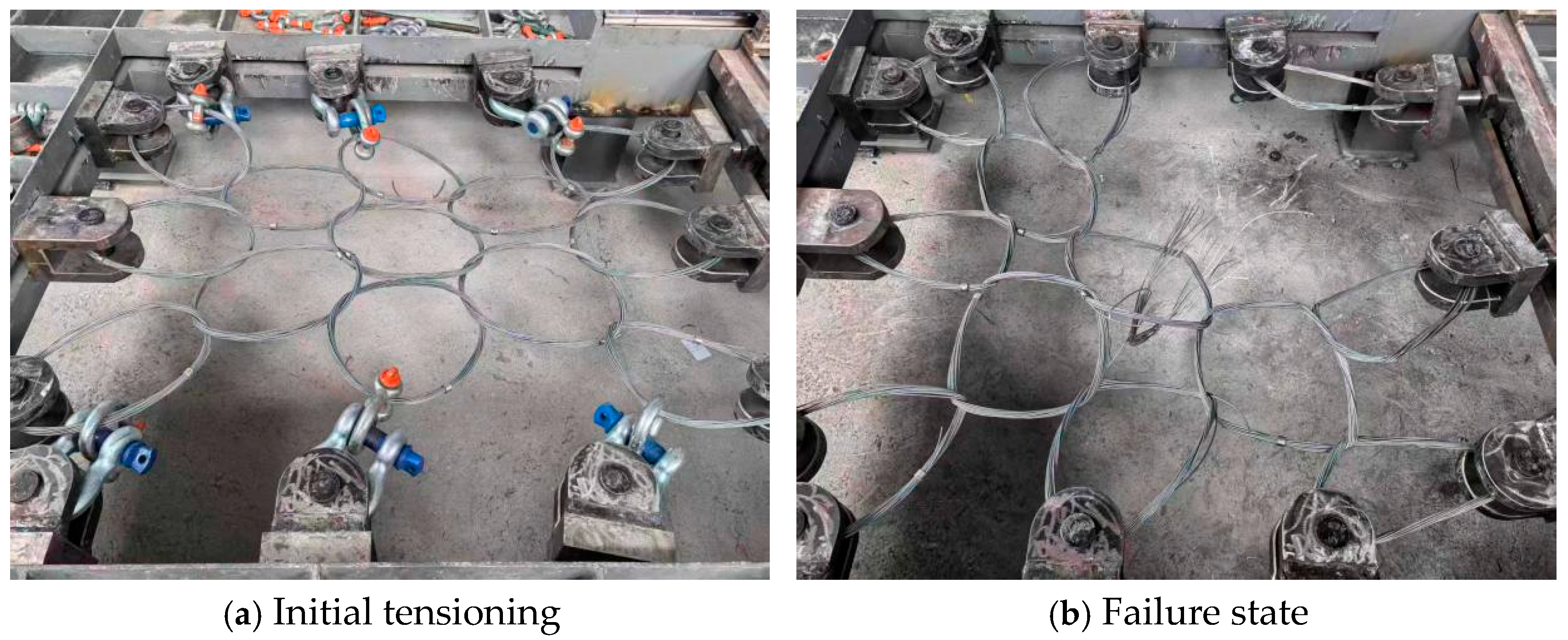
Figure 4.
Tension test results.
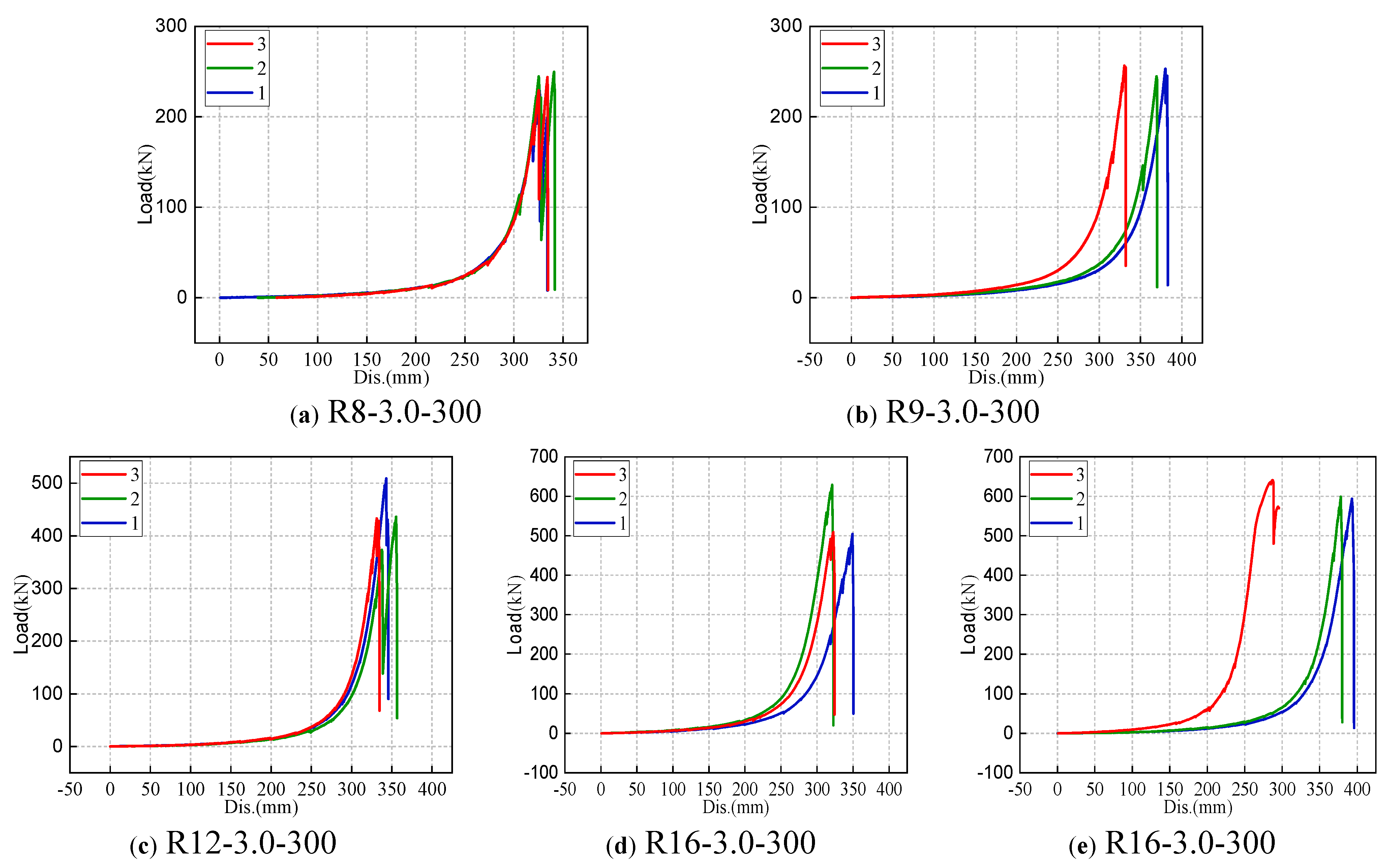
Figure 5.
Summary of tension test results.
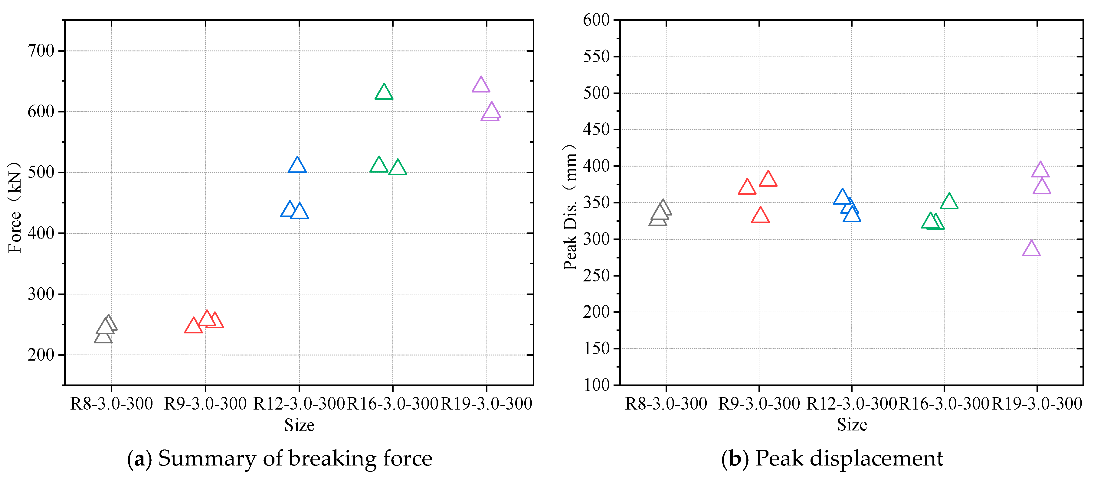
Figure 6.
Puncture test.
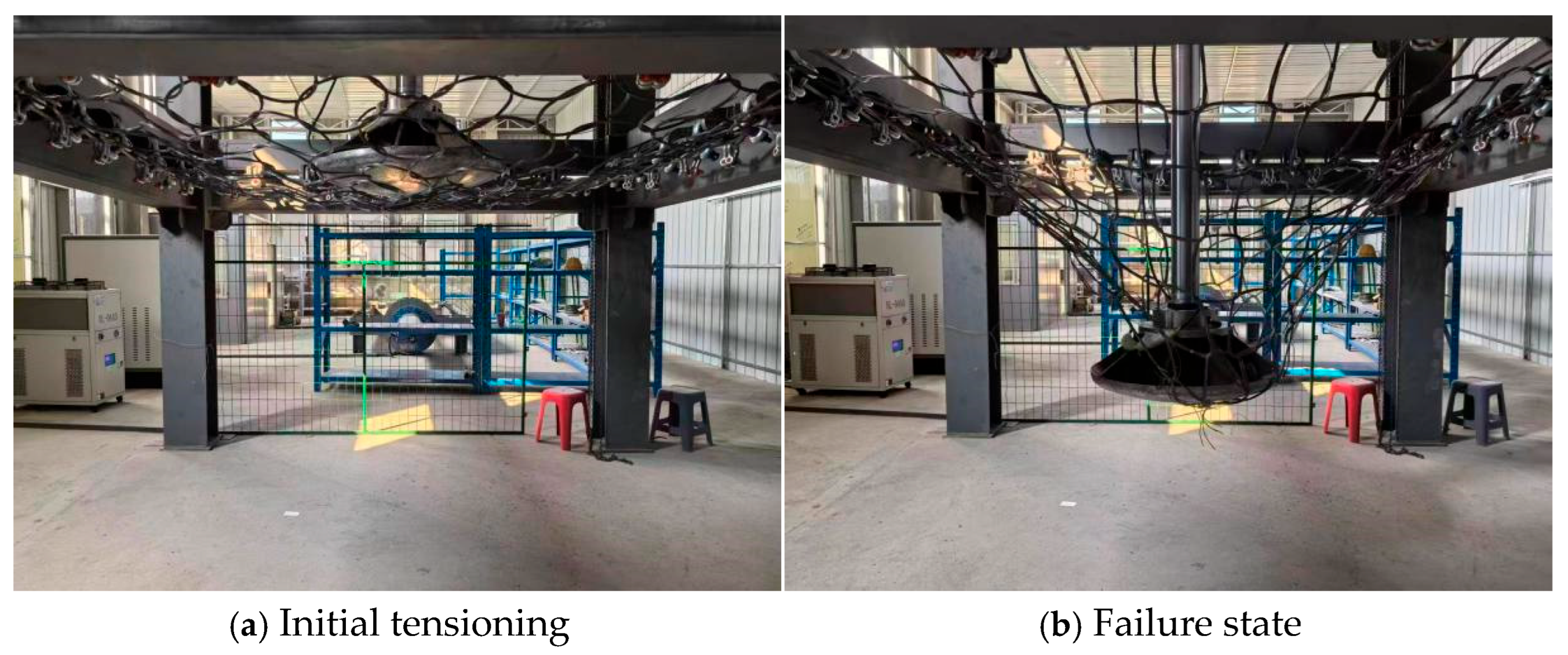
Figure 7.
Puncture test results.
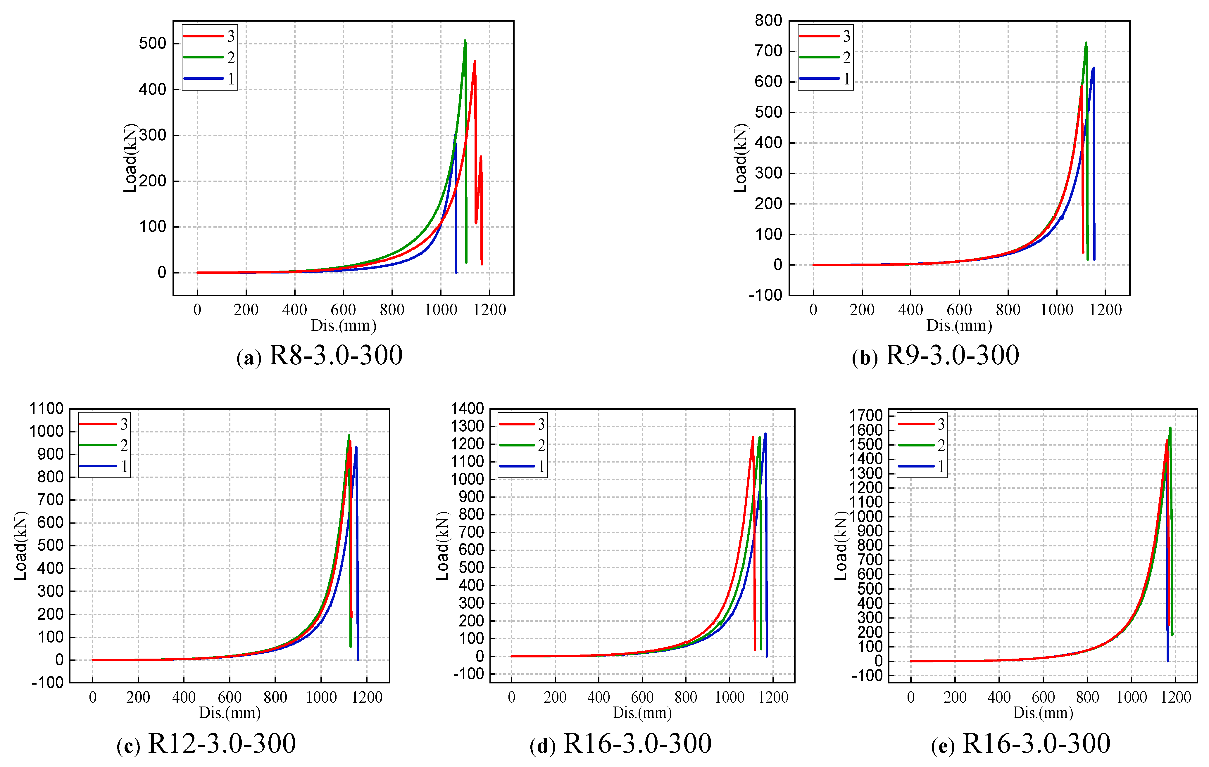
Figure 8.
Summary of puncture test results.
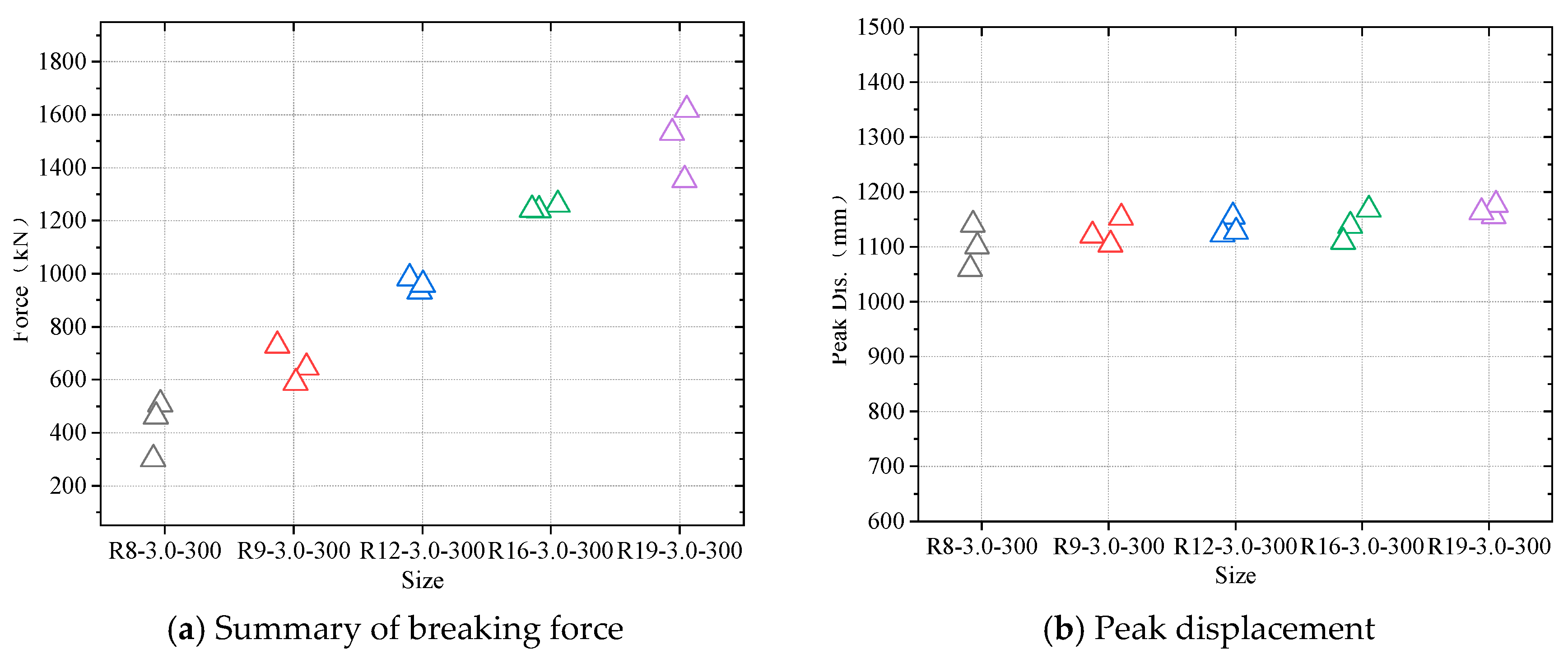
Figure 9.
Normalization of the test results.
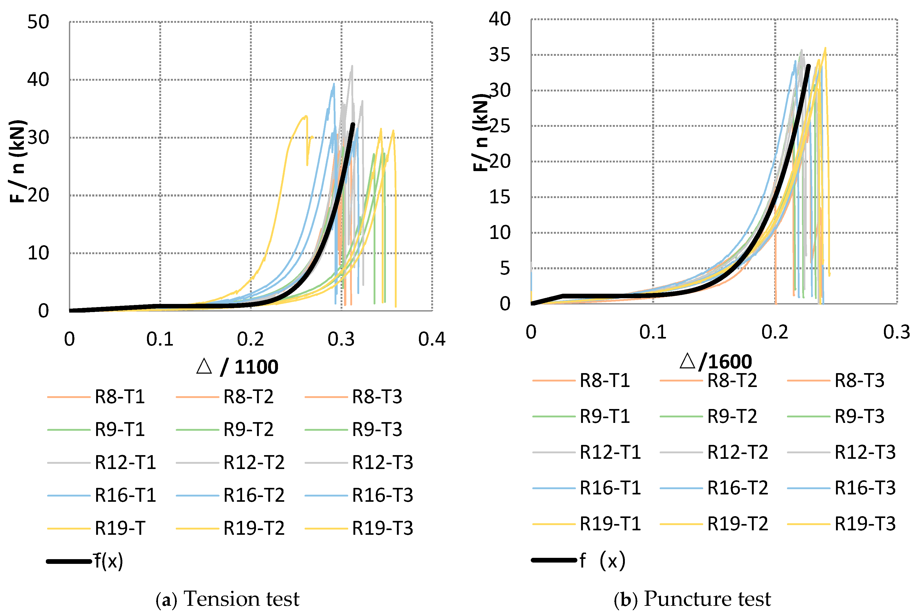
Figure 10.
Comparison between the predicted curves of the tension parallel-superposition model and the measurements of each specification.
Figure 10.
Comparison between the predicted curves of the tension parallel-superposition model and the measurements of each specification.
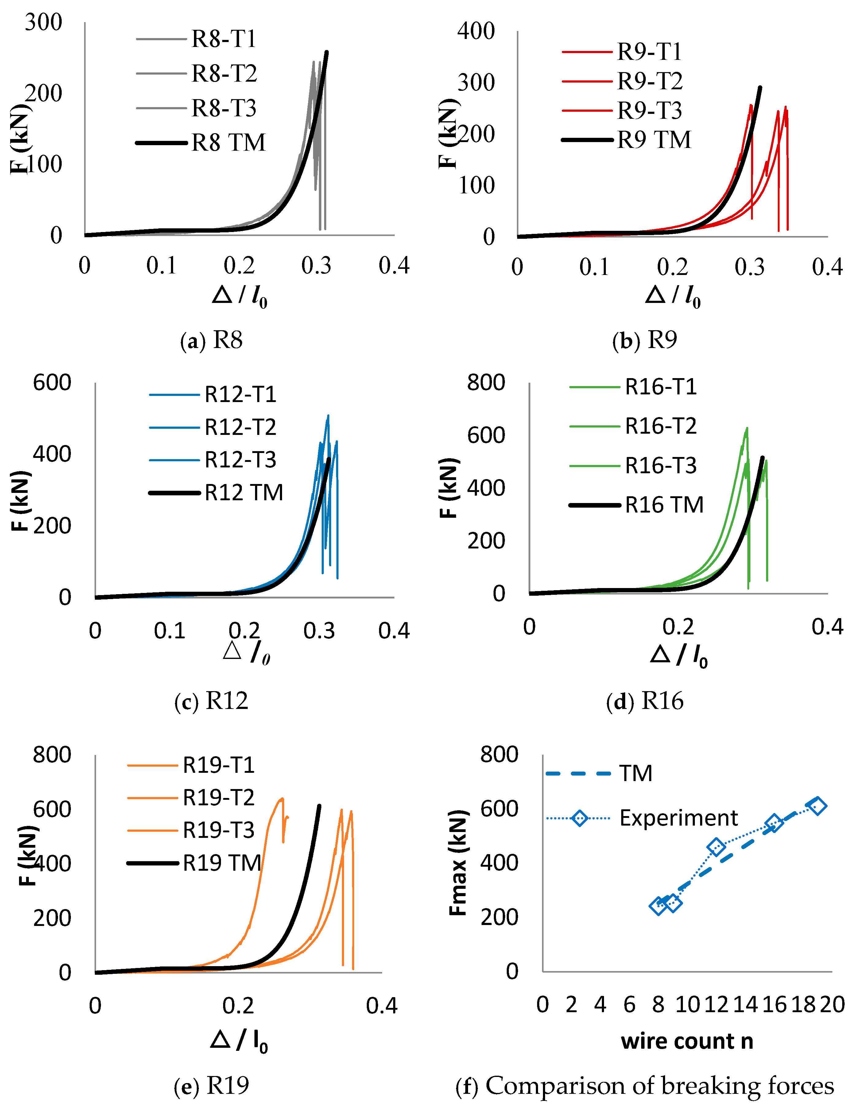
Figure 11.
Comparison between the predicted curves of the puncture parallel-superposition model and the measurements of each specification.
Figure 11.
Comparison between the predicted curves of the puncture parallel-superposition model and the measurements of each specification.
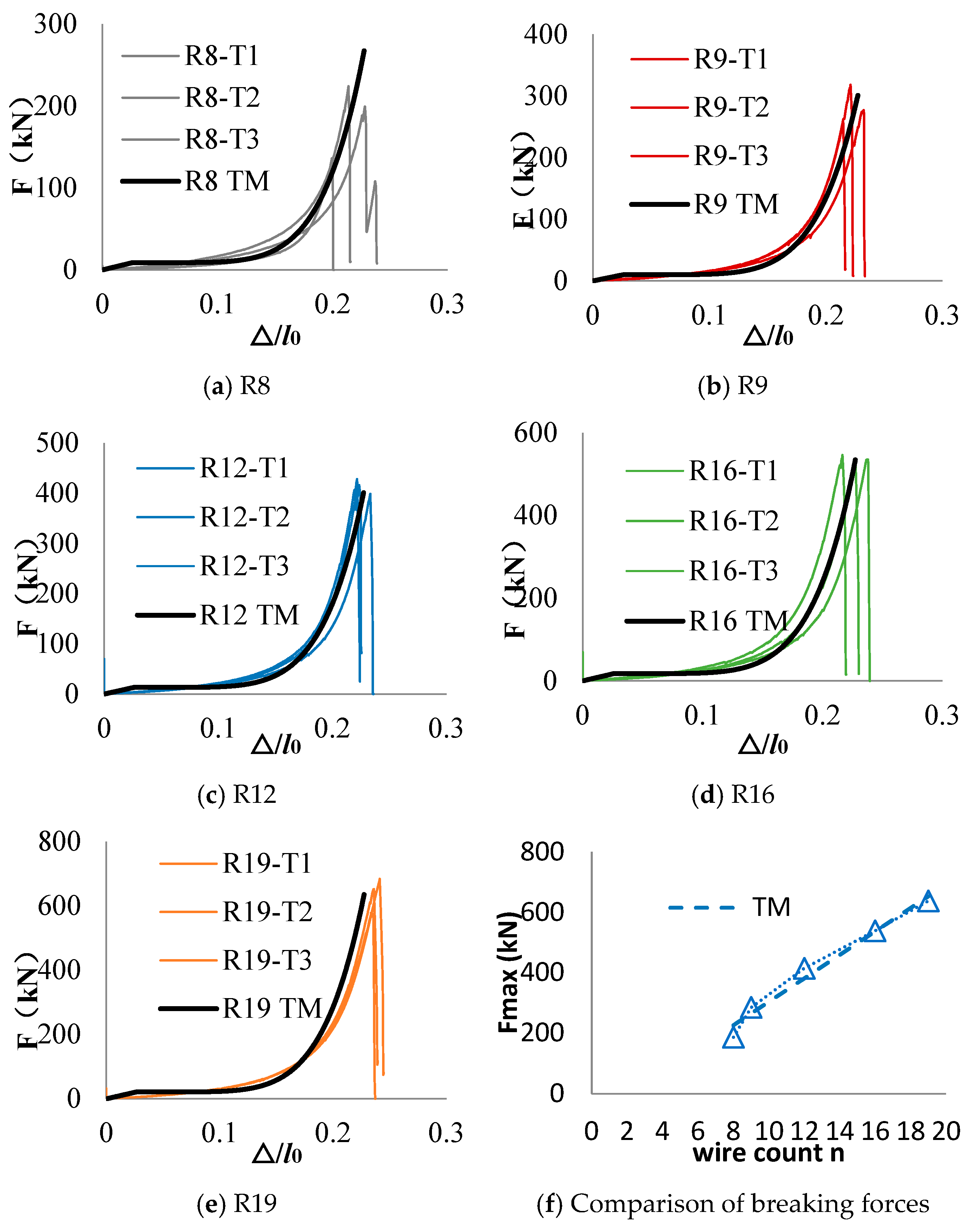
Figure 12.
Full-scale impact test.
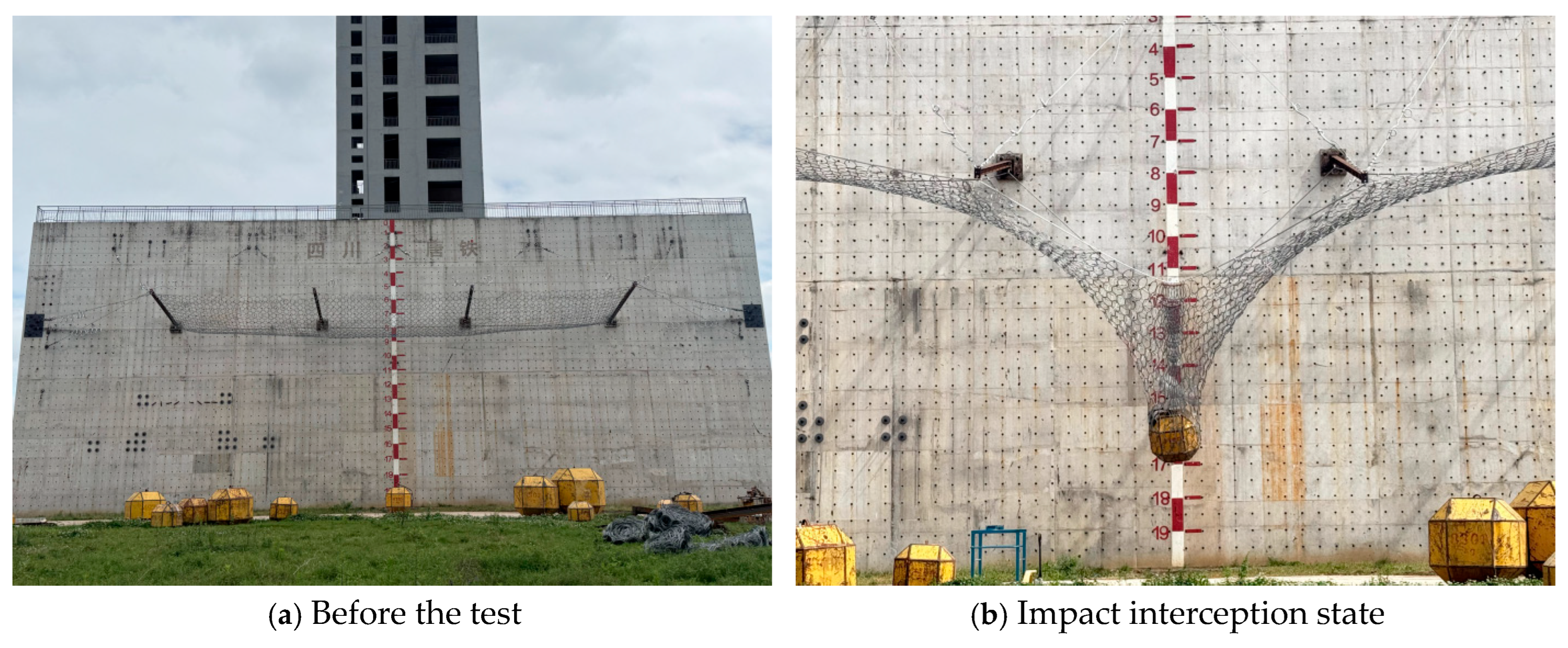
Figure 13.
Numerical simulation calculation.
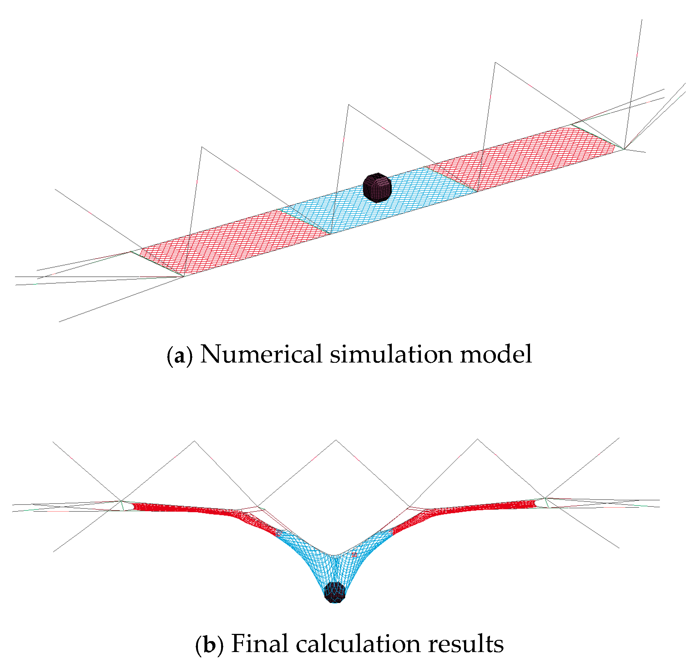
Figure 14.
Comparison of the cable force time histories.
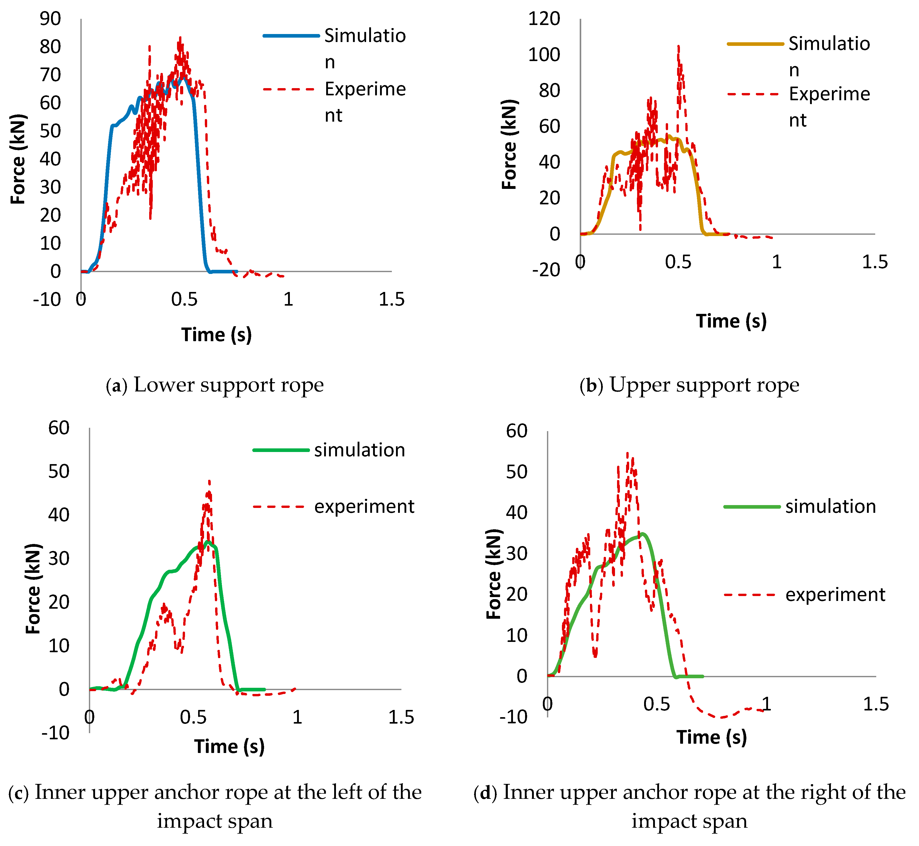
Figure 15.
Activation states of the upper and lower support-rope pressure-relief rings.
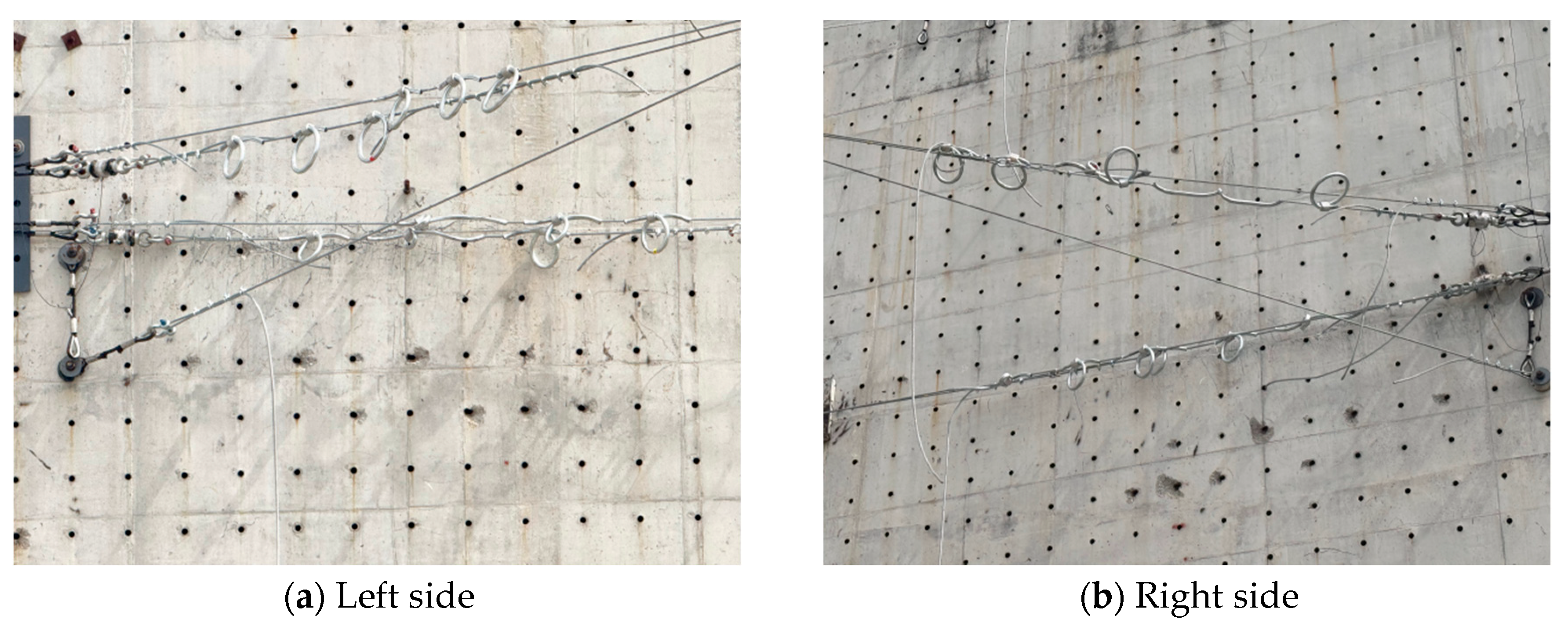
Figure 16.
Comparison of the energy dissipation of each part of the pressure-relief rings.
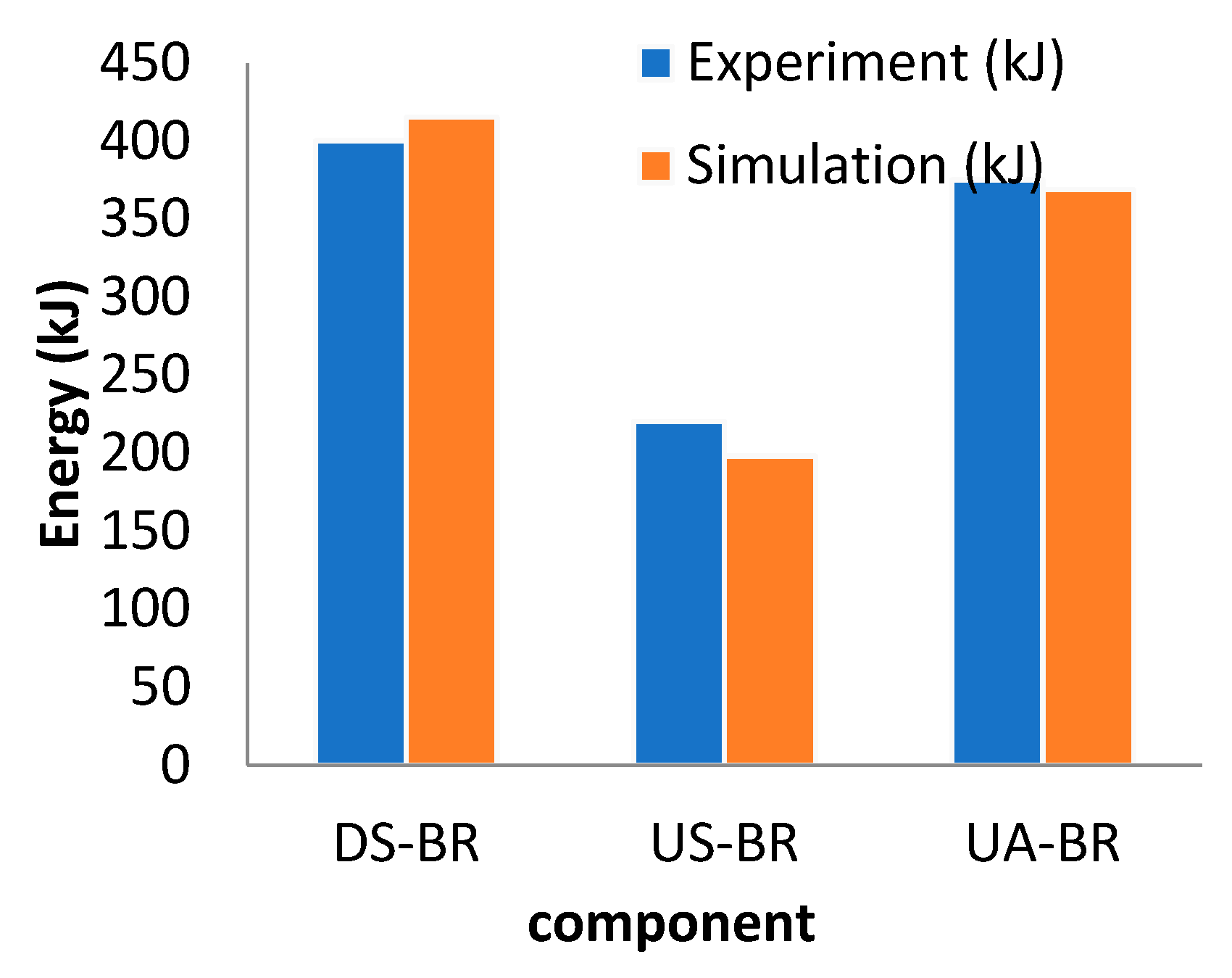

Table 1.
Specimen specifications.
| Specimen No. | Net type | Wire diameter (mm) | Ring diameter (mm) | Tension specimen size (mm) | Puncture specimen size (mm) |
|---|---|---|---|---|---|
| R8-3.0-300 | R8 | 3 | 300 | 1100×1100 | 3200×3200 |
| R9-3.0-300 | R9 | 3 | 300 | 1100×1100 | 3200×3200 |
| R12-3.0-300 | R12 | 3 | 300 | 1100×1100 | 3200×3200 |
| R16-3.0-300 | R16 | 3 | 300 | 1100×1100 | 3200×3200 |
| R19-3.0-300 | R19 | 3 | 300 | 1100×1100 | 3200×3200 |
Table 2.
Tension test results.
| Specification | Mean breaking force (kN) | Mean peak displacement (mm) |
|---|---|---|
| R8-3.0-300 | 240.63 | 333.76 |
| R9-3.0-300 | 251.31 | 359.87 |
| R12-3.0-300 | 459.3 | 343.22 |
| R16-3.0-300 | 547.89 | 331.02 |
| R19-3.0-300 | 611.22 | 348.98 |
Table 3.
Puncture test results.
| Specification | Mean breaking force (kN) | Mean peak displacement (mm) |
|---|---|---|
| R8-3.0-300 | 423.37 | 1100.18 |
| R9-3.0-300 | 654.03 | 1125.67 |
| R12-3.0-300 | 958.51 | 1135.14 |
| R16-3.0-300 | 1247.80 | 1138.27 |
| R19-3.0-300 | 1501.79 | 1164.87 |
Table 4.
Comparison of the unified piecewise constitutive model parameters for the tension and puncture cases.
Table 4.
Comparison of the unified piecewise constitutive model parameters for the tension and puncture cases.
| Parameter | Tension case | Puncture case | Physical meaning | Case difference |
|---|---|---|---|---|
| Tensioning-segment stiffness k0 | 8.75 | 42.4 | kN per unit displacement | Puncture tensioning stiffness is about 4.8 times that of tension |
| Power-hardening exponent p | 6.51 | 5.78 | — | Tension hardening is steeper |
| End of tensioning segment χ1 | 0.097 | 0.026 | — | Puncture tensioning segment is shorter |
| Peak displacement χp | 0.313 | 0.227 | — | Puncture peak displacement is smaller |
| Peak force per steel wire Fp | 32.54 | 33.4 | kN | The two cases are close |
| Bearing capacity–specification relationship | F=35.3N−30 | F=38.8N−84.9 | kN | Unilateral puncture value is comparable to tension |
| Model R2 | 0.98 | 0.983 | — | — |
Table 5.
Structural configuration of the full-scale impact test.
| Member | Configuration |
|---|---|
| Upper support rope | Two high-strength steel wire ropes, 22 mm in diameter, each equipped with three pressure-relief rings at both ends |
| Lower support rope | Same configuration as the upper support rope |
| Upper anchor rope | One high-strength steel wire rope, 22 mm in diameter, with two pressure-relief rings in series |
| Pressure-relief ring | Single pressure-relief ring calibrated to dissipate 50 kJ |
Table 6.
Comparison of the energy dissipation of the pressure-relief rings.
| Member | Test energy dissipation (kJ) |
Simulation energy dissipation (kJ) | Relative error | ||
|---|---|---|---|---|---|
| Lower support-rope pressure-relief rings | 400.0 | 415.2 | +3.8% | ||
| Upper support-rope pressure-relief rings | 220.0 | 198.1 | -10.0% | ||
| Upper anchor-rope pressure-relief rings | 375.0 | 368.8 | -1.7% | ||
Disclaimer/Publisher’s Note: The statements, opinions and data contained in all publications are solely those of the individual author(s) and contributor(s) and not of MDPI and/or the editor(s). MDPI and/or the editor(s) disclaim responsibility for any injury to people or property resulting from any ideas, methods, instructions or products referred to in the content. |
© 2026 by the authors. Licensee MDPI, Basel, Switzerland. This article is an open access article distributed under the terms and conditions of the Creative Commons Attribution (CC BY) license (http://creativecommons.org/licenses/by/4.0/).
Copyright: This open access article is published under a Creative Commons CC BY 4.0 license, which permit the free download, distribution, and reuse, provided that the author and preprint are cited in any reuse.