

Submitted:
11 August 2026
Posted:
12 August 2026
You are already at the latest version
Abstract
Today’s conventional lithium-ion battery technology used for UAVs are constrained by modest specific energy values, restricting flight endurance to roughly 10–40 minutes for small-platform configurations. Therefore, the of hydrogen fuel cell technology for unmanned aerial vehicles (UAVs) has attracted growing interest from the both military and civilian aviation sectors. In contrast, Proton Exchange Membrane Fuel Cells (PEMFCs), when integrated with Type V hydrogen gaseous tanks, offer high energy densities and electrochemical conversion efficiencies, making them the most promising alternative propulsion energy source for extended-endurance missions. This new technology refers to lightweight materials such as carbon fiber reinforced polymer composite and structural adhesives utilized for assembling, which have already remarkable application in the aerospace industry. This review systematically examines the fundamentals of PEMFC technology, hydrogen storage systems, hybrid power system architectures, energy management strategies, safety requirements, representative field demonstrations, economic and environmental assessments, and the principal technical barriers and open research questions. Advanced thermal management, emerging electrode and membrane materials, and artificial intelligence-assisted energy management algorithms are identified as the defining factors that will determine whether hydrogen-powered UAV technology achieves commercial and operational maturity.
Keywords:
unmanned aerial vehicles
; hydrogen fuel cell
; PEMFC
; hybrid power system
; energy management
; hydrogen storage
; eVTOL
1. Introduction
Unmanned aerial vehicles have become a critical component of modern aviation, driven by rapid technological advances across both civilian and military domains over the past decade [1]. Their operational utility spans a wide spectrum—from precision agriculture and infrastructure inspection to disaster response and defense applications—and their overall effectiveness is determined in large part by the performance characteristics of their onboard power systems [2]. UAVs are typically classified by maximum take-off weight, operational range, and altitude ceiling into nano/micro, mini, tactical, medium-altitude long-endurance (MALE), and high-altitude long-endurance (HALE) categories, each carrying distinct power requirements [3]. Table 1 shows the classification of UAVs according to their power requirements, maximum take-off weight, range and altitude.
Lithium polymer (LiPo) and lithium-ion (Li-ion) battery technologies currently dominate the market. Despite presenting a reasonably favorable profile in terms of specific energy (150–260 Wh/kg) and power density (500–2800 W/kg), these chemistries impose chronically short operational windows following the high-power demands of take-off and maneuvering. Flight endurance in small-class UAVs is typically limited to 10–40 minutes [4]. This constraint produces serious operational limitations for applications demanding sustained loiter time, including precision crop treatment, power-line inspection, and persistent military reconnaissance.
Hydrogen fuel cell technology is among the most promising candidates for overcoming these limitations. The gravimetric energy content of hydrogen as a carrier is 33.3 kWh/kg, comparable to conventional liquid hydrocarbon fuels[5,6]. Hydrogen fuel cells offer zero exhaust emissions (water vapor only), a low thermal and acoustic signature, electrochemical conversion efficiencies of 40–60%, and specific energy values 4–5 times greater than those of state-of-the-art rechargeable batteries [7]. Reported flight endurance Figures span a wide range depending on platform design and hydrogen storage method. Among commercially accessible systems, endurance values of 85–331 minutes have been documented under standard conditions. Under controlled experimental conditions, Intelligent Energy’s 800 W fuel cell aboard a MetaVista platform established a Guinness World Record of 727 minutes. In a separate achievement, a six-rotor platform developed by Xinyan Chuangneng demonstrated 331 minutes of uninterrupted flight in a single sortie.
Three converging factors make this moment decisive for hydrogen UAV technology: (i) accelerating regulatory pressure to reduce aviation emissions under ICAO’s Carbon Offsetting and Reduction Scheme for International Aviation (CORSIA) and equivalent national mandates; (ii) the rapid cost reduction of green hydrogen production via alkaline and PEM electrolysis, which reached below USD 5/kg in several regions by 2024; and (iii) expanding UAM and HALE demand that battery energy density fundamentally cannot satisfy. Against this backdrop, PEMFC systems have transitioned from laboratory curiosities to commercially deployed propulsion solutions within a decade [8].
This review evaluates the current state of the technology from a systems-level perspective, complementing single-domain reviews that have addressed specific subsystems [9]. The scope encompasses PEMFC fundamentals and operating principles, hydrogen storage methods, system integration strategies, hybrid power architectures, energy management algorithms, safety requirements and regulatory frameworks, case studies from fixed-wing and multi-rotor platforms, economic and environmental assessments, and the principal barriers to widespread adoption together with open research directions. The review draws on articles indexed in Web of Science and Scopus published between 2007 and 2026, using the search terms “hydrogen fuel cell UAV,” “PEMFC unmanned aerial vehicle,” “hybrid fuel cell UAV energy management,” and “hydrogen storage drone.” Inclusion criteria required either experimental demonstration, system-level modelling with validated results, or substantive technical review of PEMFC-based UAV subsystems.
Figure 1 presents a Ragone diagram that plots specific energy (Wh/kg) against specific power (W/kg) for the principal energy storage and conversion technologies considered for UAV propulsion. The diagram clearly illustrates that lithium-ion and lithium-polymer batteries occupy a region of moderate specific energy (150–260 Wh/kg) with relatively high specific power, whereas hydrogen fuel cells (PEMFC) offer substantially higher specific energy (250–1000 Wh/kg) at lower instantaneous power output. Supercapacitors, by contrast, are positioned at the high-power, low-energy extreme. The shaded overlap zone between fuel cells and batteries defines the design space where hybrid FC–battery architectures are required to satisfy both high-energy endurance and high-power transient demands simultaneously, providing the graphical rationale for the hybrid power system architectures discussed in Section 3.
2. Fundamentals of Hydrogen Fuel Cells
Hydrogen fuel cells convert the chemical energy of hydrogen into electrical energy through electrochemical oxidation. Because this process bypasses thermodynamic cycle limitations that constrain heat engines, the theoretical conversion efficiency exceeds that of conventional internal combustion power plants [10,11].
The fundamental electrochemical reactions in a PEMFC are:
Anode: H₂ → 2H⁺ + 2e⁻
Cathode: ½O₂ + 2H⁺ + 2e⁻ → H₂O
Net reaction: H₂ + ½O₂ → H₂O + heat + electrical work
At the anode, hydrogen gas dissociates into protons (H⁺) and electrons. Protons are conducted across the polymer electrolyte membrane to the cathode, while electrons travel through the external circuit, performing electrical work. At the cathode, protons, electrons, and oxygen combine to produce water as the sole reaction product. This reaction corresponds to a theoretical open-circuit voltage of 1.23 V; in practice, cell voltages under load typically fall within the range of 0.6–0.8 V. A PEMFC stack consists of the following principal components:
Membrane Electrode Assembly (MEA): The MEA comprises the proton exchange membrane, anode and cathode gas diffusion layers (GDLs), and platinum-group catalyst layers. Proton conductivity, membrane durability, and catalyst layer degradation mechanisms [12] govern overall stack hydration management are critical parameters that govern system efficiency directly [13].
Figure 2 illustrates the internal architecture of a PEMFC stack, showing the sequential arrangement of membrane electrode assemblies (MEAs), gas diffusion layers (GDLs), and bipolar plates. The diagram identifies the hydrogen inlet path at the anode side, the air/oxygen supply at the cathode side, and the integrated cooling channels embedded within the bipolar plate structure that regulate operating temperature. The compact planar stacking configuration shown is the predominant geometric approach adopted in UAV-specific lightweight PEMFC designs, where minimizing total stack height and gravimetric mass while maintaining uniform reactant distribution across the active membrane area are the central design constraints. The MEA—comprising the proton exchange membrane, catalyst layers, and GDLs—is identified as the electrochemically active core of each individual cell, and its degradation characteristics directly govern overall stack service life.
Bipolar Plates: Bipolar plates provide gas flow channels, cooling passages, and electrical interconnections within the stack, and account for a large fraction of total stack mass and volume. For UAV applications, where gravimetric efficiency is paramount, plates fabricated from graphite composites, titanium, or aluminum alloys are preferred [14].
Gas Diffusion Layers (GDLs): GDLs distribute reactant gases uniformly over the catalyst layer surface and facilitate product water removal. They are typically fabricated from carbon paper or carbon cloth.
2.1. Fuel Cell Types and Performance Comparison
The principal fuel cell types relevant to UAV propulsion are summarized in Table 2, with Technology Readiness Level (TRL) estimates for UAV deployment added to facilitate comparative assessment.
PEMFC is the dominant approach in UAV applications due to fast cold-start capability and near-ambient operating temperature. SOFC systems — proposed for high-altitude long-endurance platforms in gas-turbine hybrid configurations [15] — require 20–60 minutes of pre-heating, eliminating them from most tactical mission profiles. DMFC systems offer logistical simplicity through liquid methanol storage but lack the power density needed for high-power take-off phases. AFC systems require CO₂ scrubbing equipment that adds mass and complexity incompatible with small UAV platforms. Efficiency analysis in PEMFC systems encompasses three primary loss mechanisms: activation losses dominate in the 5–8 A current range, ohmic losses govern behavior between 8 and 20 A, and concentration losses drive voltage degradation above 20 A. Experimental evidence indicates that increasing current from 5 A to 10 A produces a 7% efficiency reduction, and increasing from 25 A to 30 A causes an 18.4% reduction [16]. The optimal operating region is accordingly defined within the 15–20 A current range.
Figure 3 presents the characteristic polarization curve (cell voltage vs. current density, left axis) and the corresponding power density curve (right axis) for a representative PEMFC under UAV operating conditions. Three distinct performance regions are identifiable in the polarization curve: (i) the activation loss region at low current densities (0–5 A), where open-circuit voltage drops steeply from the theoretical 1.23 V due to sluggish electrode kinetics; (ii) the ohmic loss region at intermediate current densities (8–20 A), where voltage decreases at an approximately linear rate governed by membrane and contact resistance; and (iii) the concentration loss region at high current densities (above 20 A), where rapid voltage collapse occurs due to reactant mass transport limitations at the catalyst layer. The power density curve reaches a maximum at the peak power operating point, while the optimal efficiency operating window—defined in the 15–20 A range as discussed in Section 2.1—is located on the descending slope of the polarization curve, ahead of the concentration loss onset. The 7% and 18.4% efficiency reductions associated with incremental current increases cited in the text can be directly traced to the respective slopes of the two loss regions visible in this figure.
From a thermal efficiency standpoint, approximately 50% of total hydrogen energy input is converted to electrical power, 45% is dissipated as heat, roughly 6% represents unreacted hydrogen losses, and the remaining 5% drives internal water evaporation [4]. In idle mode, system efficiency falls to approximately 11.4%, whereas under peak power output conditions it reaches 66.5%.
2.2. Hydrogen Storage Technologies
The most widely deployed hydrogen storage method in current UAV systems is compressed gaseous storage in high-pressure cylinders, classified into five structural categories [17]:
- Type I (All-Metal — Steel): Operating pressure: 17.5–20 MPa; gravimetric hydrogen fraction: ~1%; service life: 15 years. Heaviest option has limited structural safety margins.
- Type II (Metal Liner with Hoop Winding): Operating pressure: 26.3–30 MPa; gravimetric hydrogen fraction: ~1.5%; service life: 15 years.
- Type III (Metal Liner with Full Composite Overwrap): Operating pressure: 30–70 MPa; gravimetric hydrogen fraction: 2.4–4.1%; storage density: 35–40 g/L; service life: 15–20 years. Suitable for mini and tactical UAV applications.
- Type IV (Polymer Liner with Carbon Fiber Composite): Operating pressure: >70 MPa; gravimetric hydrogen fraction: 2.5–5.7%; storage density: 38–40 g/L; service life: 15–20 years. Type IV tanks are 39.2% lighter than Type I equivalents and represent the one of preferred options for UAV integration.
- Type V (Linerless Carbon Fiber Composite): Operating pressure: >72 MPa; gravimetric hydrogen fraction: 8–12%; storage density: 25–40 g/L; service life: 15–20+ years. Type V tanks are 10-30% lighter than Type IV equivalents and represent the best option for UAV integration.
The selection between Type III and Type IV involves a trade-off between gravimetric efficiency and long-term structural integrity. While Type IV offers superior mass performance, critical for mini-class UAVs with MTOW below 2 kg, the polymer liner undergoes hydrogen-induced permeation more readily than metallic liners, and micro-crack propagation in the carbon fiber overwrap under cyclic pressurization remains an open durability question with direct implications for operational safety [4,17]. This implies that UAV-specific qualification protocols must include coupled vibration–pressure fatigue testing at representative blade-pass frequencies, distinct from the fill-cycle-only methodology of current automotive standards (EC79, ISO 15869) — a gap that requires dedicated test infrastructure and updated certification guidance from EASA and FAA.
Currently, Type IV hydrogen storage tanks are employed by several automotive manufacturers, including BMW, Toyota, Hyundai, and Honda, Nissan [18,19,20,21,22,23]. These tanks comprise a polymer liner fully wrapped with carbon fibre-reinforced polymer (CFRP) composites [20,21,22,23,24,25,26,27]. In contrast, Type V tanks [28,29,30,31,32,33,34]are linerless structures fabricated entirely from fibre-reinforced polymer composites, making them significantly lighter than Type IV tanks. Although Type V technology remains under development and has not yet reached full technological maturity, these tanks are expected to withstand operating pressures of up to 720 bar while offering substantial reductions in structural weight. Figure 4 illustrates the different types of hydrogen storage tanks currently available.
Despite the capability of Type IV tanks to withstand high internal pressures and satisfy the stringent requirements of automotive applications [19], they remain relatively expensive and insufficiently lightweight for weight-sensitive sectors such as aerospace. Consequently, Type V tanks have become a major focus of research, particularly for aviation and unmanned aerial vehicle (UAV) applications [35,36,37,38], in addition to the automotive industry. Owing to their ultra-lightweight design, Type V tanks are anticipated to provide a cost-effective, safe, and mass-producible solution while enabling conformal geometries that can be integrated efficiently into complex structures [39]. These characteristics make Type V tanks particularly attractive for aerospace applications, especially drones and UAVs, where several manufacturers have already initiated development programmes aimed at their adoption [35,36,37,38,40].
Nevertheless, several critical challenges continue to hinder the widespread implementation of Type V hydrogen storage systems. One of the most significant issues is hydrogen permeation [41,42,43,44,45,46,47,48,49], which arises from the exceptionally small molecular size and low molecular weight of hydrogen. These characteristics enable hydrogen molecules to diffuse through the polymer matrix and, in some cases, along fibre-matrix interfaces within the composite wall. Such diffusion may eventually lead to hydrogen leakage, progressive degradation of the composite constituents, and a consequent reduction in the structural integrity and storage efficiency of the tank [50,51].
Permeation is a physical transport phenomenon defined as the steady-state diffusion of atoms or molecules through a solid material under a pressure gradient [52]. The permeation process generally consists of three sequential stages [45]: (1) absorption of hydrogen at the material surface, (2) diffusion through the material, and (3) desorption from the opposite surface. Although permeation is unavoidable to some extent, prolonged hydrogen exposure can significantly deteriorate the mechanical performance of composite materials, particularly those employed in Type V tanks. Under sustained internal pressure, the polymer matrix is susceptible to microcrack initiation, which may progressively evolve into fibre-matrix interfacial debonding as indicated in Figure 5. Continued damage accumulation can subsequently lead to hydrogen leakage, laminate delamination, fibre fracture, and ultimately catastrophic failure of the pressure vessel [53,54]. Considering the highly flammable nature of hydrogen, any leakage poses a significant safety hazard.
Another degradation mechanism observed in laminated composite hydrogen tanks is blistering, which refers to the formation of gas-filled cavities within the composite structure. Blistering occurs when hydrogen diffuses into the composite during repeated filling and emptying cycles and becomes trapped within the material, generating localized gas pockets and additional internal stresses [53]. Over time, these cavities may grow in size, thereby compromising the structural integrity of the tank [54,55,56]. Furthermore, cavity formation disrupts the uniform stress distribution within the laminate, creating localized stress concentrations [57] that promote interlaminar delamination and further structural degradation [50,51].
Hydrogen embrittlement represents another critical degradation mechanism affecting composite hydrogen storage systems. During long-term exposure, hydrogen diffuses into the composite constituents, particularly the polymer matrix and fibre-matrix interface, altering the mechanical response of the material from relatively ductile to increasingly brittle behaviour [58]. Elevated temperatures generated during rapid refuelling accelerate hydrogen diffusion into the composite wall, thereby intensifying the embrittlement process and further reducing the long-term durability and reliability of the storage tank.
This challenge compels tank designers to develop robust and reliable designs that minimize the risk of catastrophic failure. Achieving this objective requires a comprehensive understanding of the fundamental behaviour of laminated composite materials, including the constituent fibres, polymer matrix, and the adhesive systems employed in the assembly of the tank components.
As the mainstream materials for hydrogen tanks type V, laminated composite materials have been increasingly adopted in the aerospace and automotive industries owing to their high specific stiffness and strength, low density, excellent fatigue performance, and superior corrosion and damage resistance [59,60,61,62,63]. In modern commercial aircraft, such as the Airbus A380 and the Boeing 787 Dreamliner, composite materials account for approximately 50% of the structural weight and are extensively employed in both primary and secondary load-bearing components. Their widespread adoption highlights the pivotal role of composite materials in the design of next-generation aircraft. Their outstanding strength-to-weight ratio enables significant weight reduction, leading to improved aerodynamic efficiency, enhanced manoeuvrability, lower fuel consumption, and reduced operating costs [64].
With respect to Type V hydrogen storage tanks, extensive knowledge of laminated composite materials, adhesive bonding technologies, and pressure vessel design is essential, ranging from the fundamental mechanical behaviour of constituent materials to advanced manufacturing and assembly techniques [65]. Since hydrogen permeation and leakage remain the principal challenges associated with linerless composite pressure vessels, considerable research has focused on developing effective mitigation strategies. One promising approach involves the application of polymeric barrier materials [66,67] as internal surface layers on the composite laminate to reduce hydrogen permeation. In addition, advanced adhesive bonding technologies have the potential to minimize leakage at critical interfaces, particularly in joints connecting the metallic boss assembly to the composite tank wall [68,69,70,71].
The design of Type V tanks must also account for the mechanics of thin- and thick-walled pressurised vessels [72,73]. Furthermore, the thermodynamic behaviour of hydrogen during rapid filling and discharge cycles within the confined tank volume is recognised as a critical phenomenon that directly influences the structural response of the composite materials [70,71]. The combined effects of pressure, temperature, and hydrogen diffusion necessitate a comprehensive understanding of the material behaviour under a wide range of environmental and service conditions.
Reliable material characterisation constitutes the foundation of robust structural design. Accurate determination of the mechanical properties of structural adhesives used in the assembly of Type V tanks, particularly for bonding the metallic boss to the composite shell, is essential because these properties serve as critical input parameters for numerical simulations and structural integrity assessments. Consequently, experimental techniques developed for the tensile [74] and shear [75] characterisation of structural adhesives must provide reliable and reproducible stress–strain data, as inaccuracies in the measured material properties can significantly compromise the accuracy of design predictions.
Because structural adhesives exhibit a broad spectrum of mechanical behaviours, no single experimental methodology is universally applicable. For example, non-contact optical measurement techniques are generally preferred for determining the tensile stress–strain response of highly flexible adhesives, whereas conventional contact extensometers are often suitable for relatively stiff adhesives. Similarly, accurate measurement of the shear behaviour requires carefully designed experimental procedures, with the testing methodology depending on whether the adhesive is evaluated as a thin bonded layer [76] or as a bulk material [75]. Appropriate selection of structural adhesives is equally important because joint performance strongly depends on the loading mode and stress distribution. Ductile adhesives, despite exhibiting lower ultimate strengths, often outperform brittle adhesives in joints containing significant stress concentrations owing to their superior strain-to-failure and enhanced capacity for stress redistribution [77].
Equally important is the accurate characterisation of the laminated composite materials that constitute the primary load-bearing structure of Type V tanks. Composite laminates incorporating fibre orientations of ±θ are commonly employed to achieve the required balance between hoop and axial load-carrying capacity. Reliable experimental characterisation over both low-stress [78] and high-stress regimes [79] is therefore essential for obtaining dependable design data. Furthermore, a comprehensive understanding of the behaviour of adhesively bonded composite joints in various configurations [65] provides valuable insight for the design of hydrogen storage systems, where bonded assemblies are widely employed. The mechanical response of these joints under quasi-static, fatigue, and impact loading [80,81,82,83,84], as well as under different environmental conditions, including elevated temperatures and humidity [85,86], represents critical information for predicting the long-term durability, safety, and reliability of Type V hydrogen storage tanks.
Although hydrogen possesses the highest gravimetric energy density of all conventional fuels, its inherently low volumetric energy density necessitates storage at very high pressures, resulting in a significant demand for storage volume [87]. Consequently, efficient utilisation of the available space within a vehicle has become a major design challenge, particularly in weight-sensitive applications such as aerospace. This challenge has stimulated the development of Type V linerless composite pressure vessels capable of adopting conformal geometries that maximise both gravimetric and volumetric storage efficiencies [31,88,89].
Conventional high-pressure hydrogen storage vessels are predominantly cylindrical or spherical because these geometries minimise stress concentrations under internal pressure [35,36,37,38]. However, such shapes utilise the available installation volume inefficiently, leaving considerable unused space within the vehicle architecture (see Figure 6) To overcome this limitation, increasing attention has been directed towards the development of conformal Type V pressure vessels, such as rectangular-prism or other non-axisymmetric geometries, which can be integrated more effectively into the structural layout of vehicles (see Figure 7). These designs have the potential to maximise the utilisation of available space while simultaneously reducing overall vehicle weight and improving storage efficiency [40,90].
Despite the growing interest from stakeholders, particularly within the aerospace sector, publicly available research on conformal Type V hydrogen tanks remains limited [23,42]. Nevertheless, the increasing commitment of aerospace industries to hydrogen-powered propulsion systems has intensified research efforts aimed at integrating high-pressure hydrogen storage into aircraft structures [42]. Such integration enables innovative vehicle architectures in which the storage tanks become an inherent part of the airframe rather than separate payload components. As illustrated in Figure 7, the future hydrogen-powered aircrafts are expected to incorporate storage vessels with geometries that complement the overall aerodynamic profile, thereby improving aerodynamic efficiency, reducing drag, and enhancing both safety and structural integration.
This design philosophy represents a fundamental departure from conventional cylindrical pressure vessels. Rather than functioning solely as energy storage devices, conformal composite tanks can simultaneously serve as structural members within the airframe. One representative example is the integration of hydrogen storage tanks into the wing structures of light aircraft (Figure 7), where the tanks not only store hydrogen but also contribute to the structural stiffness and load-carrying capability of the wing. Such multifunctional structures offer substantial opportunities for weight reduction and improved system efficiency, which are particularly valuable for aerospace applications.
Realisation of these advanced conformal pressure vessels requires materials and manufacturing technologies capable of producing lightweight, high-strength, and durable structures with complex geometries. The selected materials must exhibit excellent corrosion resistance, high damage tolerance, compatibility with advanced surface treatments and adhesive bonding processes, and, critically, low hydrogen permeability and leakage. Laminated fibre-reinforced polymer composites, together with advanced adhesive bonding technologies, satisfy many of these demanding requirements and therefore constitute the principal enabling technologies for next-generation hydrogen storage systems. Their exceptional design flexibility and multifunctional capabilities have motivated significant international research initiatives aimed at developing new classes of composite materials and manufacturing technologies for future hydrogen-powered vehicles [93,94,95].
Cryogenic liquid hydrogen storage provides high volumetric energy density at 71 kg/m³ at −252.87 °C, with a mass storage efficiency of 14.2%, a gravimetric energy density of 5.57 kWh/kg, and a volumetric energy density of 1.68 kWh/L—translating to roughly 85% longer flight endurance compared to compressed gas systems of equivalent tank mass. The MetaVista multi-rotor platform developed in South Korea achieves flight endurance 727 minutes (12.1 hours, Guinness World Record, 2019) using a 6 L liquid hydrogen tank, establishing the current endurance record for commercial multi-rotor platforms. Ground handling complexity and infrastructure cost remain the primary barriers to large-scale commercialization [16]. Cryo-compression raises mass storage efficiency to 7.38%, volumetric density to 0.045 kg H₂/L, and gravimetric energy density to 2.46 kWh/kg, but specialized infrastructure limits its UAV applicability at present.
Sodium Borohydride (NaBH₄) hydrolysis has been employed in UAV platforms developed by KARI and KAIST. The reaction
yields a volumetric specific energy of 739.1 Wh/L and gravimetric specific energy of 272.8 Wh/kg. However, the system-level penalty—including water supply, by-product collection vessels, and reaction chamber heating—adds 15–30% overhead mass compared to fuel weight alone, which narrows the net advantage over Type IV compressed storage for many tactical UAV classes [97]. The approximately 25-minute start-up delay is an additional operational constraint.
NaBH₄ + 2H₂O → NaBO₂ + 4H₂ [96]
Ammonia borane (NH₃BH₃) dehydrogenation at 120–180 °C offers hydrogen storage capacity up to 19.6 wt%, but slow reaction kinetics and gaseous impurity generation mean this approach remains at the research stage. Metal hydride storage (mass storage efficiency: 0.65%; gravimetric energy density: 0.26 kWh/kg) offers ambient-temperature stable storage, but low capacity and thermal management requirements limit practical deployment [98].
Compared to the gas storage, liquid hydrogen storage operates at pressures below 1 MPa, which reduces the high costs related to with the compression of gas. However, the utilization of liquid hydrogen poses challenges such as the requirement for extremely low temperatures, and boil-off losses influenced by factors including thermal insulation quality, hydrogen volume, storage duration, environmental conditions, and tank geometry [99]. Additionally, liquid hydrogen storage suffers from low energy efficiency, high overall costs, and significant energy consumption during the liquefaction process, known as the liquefaction energy penalty [100].
The energy storage performance of the principal hydrogen storage methods can be compared simultaneously across both gravimetric and volumetric dimensions. Figure 8 presents this two-axis comparison, allowing the relative trade-offs between mass efficiency and volume efficiency to be assessed directly for each storage technology class.
Figure 8 plots gravimetric energy density (Wh/kg, x-axis) against volumetric energy density (Wh/L, y-axis) for compressed gaseous hydrogen (Type III and IV cylinders at 350 and 700 bar), cryogenic liquid hydrogen, cryo-compression, sodium borohydride (NaBH₄) hydrolysis, and metal hydride storage. The diagram reveals a clear performance hierarchy: cryogenic liquid hydrogen achieves the highest volumetric density (approximately 1,680 Wh/L) owing to its storage density of 71 kg/m³ at −252.87 °C, while Type IV cylinders at 700 bar provide the most practical balance of gravimetric and volumetric performance within a structurally qualified envelope. Chemical hydride systems cluster at moderate-to-high volumetric densities but comparatively low gravimetric values, reflecting the system-level mass overhead of reaction chambers, water reservoirs, and by-product vessels. Metal hydrides occupy the lower-left quadrant, confirming their limited utility for mass-constrained UAV platforms. The Figure provides the quantitative basis for the technology selection guidance presented in the following paragraph and directly supports the design recommendations consolidated in Table 6 for each mission profile category.
For UAV design, Type III–IV cylinders remain the preferred solution for operations with endurance below 6 hours and MTOW below 25 kg. Liquid hydrogen storage is increasingly favored for missions beyond six hours where infrastructure overhead is justified. Chemical hydrides occupy a middle ground for applications where ambient-temperature storage is operationally essential and start-up delay is acceptable.
Two fundamental equations govern hydrogen UAV endurance estimation. First, the gravimetric endurance model:
where E is endurance (h), mH₂ is usable hydrogen mass (kg), LHV = 33.3 kWh/kg is the lower heating value, ηsys is system efficiency (typically 0.40–0.55 for PEMFC + drivetrain), and Pcruise is cruise power demand (kW).
E = (mH₂ × LHV × ηsys) / Pcruise
Second, the hybrid power balance equation governing instantaneous power split:
where PFC is the fuel cell output power, Pbat is battery power (positive during discharge, negative during charging), Pload is instantaneous propulsion demand, and Ploss represents converter and parasitic losses. During take-off, Pload typically reaches 2–5× cruise levels, requiring battery discharge to supplement fuel cell output [17].
PFC(t) + Pbat(t) = Pload(t) + Ploss(t)
3. System Integration and Hybrid Power Architectures
The principal limitation of standalone PEMFC operation is restricted dynamic power response — a challenge shared across electric and hybrid-electric fixed-wing propulsion architectures [101]. While fuel cells offer high energy density (250–1000 Wh/kg), their power density (10–1000 W/kg) remains lower than batteries (500–2800 W/kg) [102]. In multi-rotor UAVs, take-off power demand can be 2–5 times greater than cruise power, generating transient load requirements that standalone fuel cells cannot satisfy without oversizing the stack. Most UAV applications therefore employ hybrid power systems pairing a PEMFC with a secondary energy storage element.
Figure 9 depicts the time-resolved power demand profile of a representative multi-rotor UAV mission and shows the corresponding contributions of the fuel cell and battery subsystems throughout each distinct flight phase. During the take-off phase, the total propulsion demand spikes to 2–5 times the cruise baseline; the fuel cell output alone is insufficient to meet this transient requirement, and the battery therefore provides the supplementary peak power illustrated by the shaded positive battery contribution region. During the cruise phase, the fuel cell operates near its optimal efficiency point and simultaneously recharges the battery, represented by the negative battery power segment in the profile. During descent and landing, battery assistance again buffers the transient demand fluctuations. The Figure 9 provides direct quantitative motivation for the hybrid power architectures described in this section: the power differential between take-off and cruise—clearly visible in the profile—is the primary engineering driver for pairing a high-energy fuel cell with a high-power secondary storage element, and it demonstrates why standalone fuel cell operation without energy storage is impractical for multi-rotor UAV applications.
Parallel hybrid topology: The fuel cell and battery are connected through power electronics to the motor driver such that source supplies power as required. The battery provides supplementary power during high-demand phases while the fuel cell recharges the battery during cruise [103,104]. This is the most widely adopted configuration in UAV applications.
Series hybrid configuration: The fuel cell charges the battery, which in turn supplies the electric motor. This permits more systematic control of power flow, but additional power conversion stages reduce overall system efficiency by 5–12% depending on converter specifications [17].
Fuel cell–supercapacitor hybrids: Supercapacitors (1,000–10,000 W/kg power density) buffer rapid transient power demands, particularly during take-off, reducing PEMFC membrane exposure to high current ripple and extending stack service life [105]. However, supercapacitor energy density (5–15 Wh/kg) is substantially lower than battery equivalents, making this configuration most appropriate for missions with short, well-defined high-power transients.
A critical system-level trade-off concerns the mass and volume penalty of power electronics. The DC-DC converter required in series and active parallel topologies contributes 0.8–2.5 kg at the 500–2000 W power class, representing 10–20% of typical small UAV payload capacity [4]. For tactical UAVs in the 2–15 kg class, parallel passive hybrid configurations that bypass the need for an active DC-DC controller on the fuel cell bus offer a pragmatic alternative, trading optimization flexibility for reduced mass and complexity.
Figure 10 presents schematic circuit-level representations of the three primary hybrid power system topologies used in hydrogen UAV applications. In the parallel topology (top panel), the fuel cell and battery are directly coupled to the motor bus via a shared DC rail, enabling simultaneous or selective power delivery without a dedicated fuel cell DC-DC converter, which reduces mass and conversion losses at the cost of reduced power flow control authority. The series topology (middle panel) routes all fuel cell power through the battery as an intermediary before reaching the electric motor bus; this arrangement allows tighter state-of-charge control and more systematic energy flow regulation, but introduces additional power conversion stages that reduce overall system efficiency by 5–12%. The FC–supercapacitor topology (bottom panel) replaces the battery with a supercapacitor bank capable of absorbing and delivering high-rate transients—particularly the take-off power spike—with minimal degradation, making it well-suited for rotorcraft applications with frequent short-duration power peaks.
In certain long-endurance applications, photovoltaic panels are integrated as a third energy source. This triple-hybrid architecture is particularly effective for extended high-altitude fixed-wing UAV missions, where solar irradiance supplements onboard hydrogen reserves and improves energy autonomy [106,107].
4. Energy Management Strategies
Energy management in hybrid power systems consists of algorithms that optimize the instantaneous power split between the fuel cell and battery by accounting for the state of each source, the mission profile, and the dynamic power demand. An effective EMS must simultaneously pursue multiple objectives: minimizing hydrogen consumption, maintaining battery state of charge (SOC) within safe bounds, prolonging fuel cell service life, and maximizing mission completion probability [108,109].
Rule-based control is the simplest EMS class, governing power distribution through predefined threshold conditions and logical rules [110]. These strategies offer low computational overhead and real-time implement ability on standard autopilot hardware (Pixhawk-class microcontrollers), but their capacity to adapt to varying mission conditions is limited. Hierarchical rule sets—for instance, operating on the fuel cell alone above 80% SOC, combining both sources between 60–80% SOC, and landing on battery power alone below 60%—have been successfully applied in multi-rotor platforms [111]. Accurate real-time estimation of battery SOC and state of health (SOH) is critical to the reliability of such implementations, and AI-assisted battery state estimation is gaining traction in this domain [112]. Table 4 presents a comparison of tenders based on energy management systems.
Reinforcement learning (RL), deep neural networks, and fuzzy logic-based EMS approaches have attracted significant research interest [113,114]. Three-layer EMS frameworks—where the first layer handles fuel cell state monitoring and protection, the second performs real-time power split optimization, and the third manages mission-level energy planning—have demonstrated effective simultaneous minimization of hydrogen consumption and battery degradation in field testing [115].
A critical distinction exists between EMS performance demonstrated in simulation and deployment readiness on certified airborne hardware. Model predictive control and deep learning approaches require computational resources (>100 MIPS with hard real-time latency constraints (< 10 ms at typical EMS update rates of 10–100 Hz [109]) that exceed the capabilities of current off-the-shelf autopilot microcontrollers. Under FAA AC 20-174 (Machine Learning Aeronautical Data Assurance) and EASA SC E-19 (AI in Aviation) frameworks, no established means of compliance currently exists for data-driven flight-critical controllers, representing a near-term barrier that is likely to constrain commercial adoption regardless of technical performance. Production deployments have consequently retained rule-based or state-machine strategies, while AI-assisted EMS remains in the research domain [108,116].
5. Safety, Standards, and Regulations
The onboard carriage of pressurized hydrogen in UAVs introduces specific safety engineering requirements across three domains: structural integrity of storage vessels, leak detection and containment, and crashworthiness [4,17].
Due to hydrogen’s low molecular weight and high diffusivity, gas accumulation in enclosed spaces can form explosive mixtures (flammability limits: 4–75 vol% in air; detonation limits: 18–59 vol%) with low ignition energy (0.017 mJ). Tank materials must demonstrate resistance to mechanical impact, vibration, and thermal cycling through rigorous qualification testing. The long-term fatigue behavior and micro-crack propagation in Type IV composite cylinders under repeated pressurization cycles are open research questions with direct operational safety implications. In crashworthiness terms, the failure mode of a composite hydrogen pressure vessel under high-velocity impact—fragment projection and sudden gas release—requires design mitigation distinct from the controlled venting characteristic of battery thermal runaway events.
Hydrogen leak detection employs catalytic, electrochemical, and semiconductor sensor technologies. Multi-sensor fusion with AI-assisted anomaly detection provides rapid early warning even at low concentration levels. Emergency shut-off valves, automatic ventilation systems, and fail-safe landing procedures constitute the critical safety layers for leak scenarios. Failure Mode and Effects Analysis (FMEA) across the hydrogen system—covering regulator failure, solenoid valve malfunction, membrane rupture, and sensor failure modes—is required by both FAA and EASA certification guidance and should be integrated from the concept design phase. Hydrogen dispersion modelling in UAV fuselages under realistic ventilation conditions remains an area where published UAV-specific data are sparse. Critical regulatory frameworks and technical standards governing hydrogen fuel cell systems in unmanned aerial vehicle (UAV) applications are summarized in Table 5. The table highlights key international safety, design, and operational requirements that must be satisfied to ensure airworthiness, system reliability, and environmental compliance.
Additional relevant bodies include ISO/TC 197, SAE International (SAE AS6458), IEC/TC 105, and ICAO. National aviation authorities are developing specialized assessment criteria for type certification and operational approval of hydrogen UAV systems, with hydrogen storage safety, FMEA, safe-return-to-land behavior, MTBF thresholds, and fire and explosion resistance among the primary evaluation requirements. A particular source of uncertainty is the absence of established special condition frameworks for hydrogen UAVs equivalent to those already in place for electric propulsion in manned aircraft; manufacturers under FAA and EASA jurisdiction must currently negotiate means of compliance on a project-by-project basis.
A critical unresolved challenge specific to UAV applications concerns Type IV tank structural integrity under operational cycling. Automotive-heritage Type IV cylinder standards (EC79, ISO 15869) define fatigue life under controlled fill-cycle conditions up to 700 bar, but UAV deployment introduces additional stressors absent from ground vehicle characterization: high-frequency vibration loads at rotorcraft blade-pass frequencies (40–120 Hz), rapid thermal cycling between ground storage temperatures (−20 °C to +50 °C) and altitude environments (−50 °C at HALE operating ceilings), and accelerated micro-crack propagation in the carbon fiber composite overwrap under combined pressure and bending loads. It is known that fatigue data indicate that crack growth rates in composite outer cladding increase under conditions of simultaneous vibration and loading, compared to static loading alone[117]. For UAV certification, dedicated qualification testing at representative vibration spectra is therefore required beyond the automotive standard fill-cycle methodology.
6. Applications and Field Demonstrations
PEMFC hydrogen fuel cell technology has delivered notable achievements in lightweight, extended-endurance fixed-wing UAV platforms [118,119]. Studies conducted on platforms in the 2–25 kg class have demonstrated meaningful performance Figures under optimized design conditions [14,120]. Among the notable field test results, the 6.5 kg Hydra platform achieved a baseline endurance of four hours. Optimized PEMFC–battery hybrid systems have extended flight endurance by a factor of 3.76 compared to battery-equivalent platforms [16]. The U.S. Navy’s Ion Tiger—a fixed-wing platform of approximately 16 kg—established a continuous flight record of 48 hours using liquid hydrogen, providing the clearest benchmark for long-endurance hydrogen propulsion at the tactical UAV scale. A high-altitude fixed-wing UAV developed by Renau et al. employs a bespoke 400 W high-temperature PEMFC (HT-PEMFC, operating at 120–180 °C) and achieves five times the endurance of a battery-equivalent platform at altitudes up to 3,000 m [121]. Notably, HT-PEMFC systems require a pre-heating period of 10–30 minutes before reaching operating temperature; cold-start behavior at sub-zero ambient temperatures for conventional PEMFC systems was characterized separately through water-thermal management modelling that established intra-cell design criteria for sub-freezing operation [122].
In the rotary-wing segment, which has seen substantial market growth since 2015, field tests across a range of power classes and endurance targets exhibit a wide performance envelope. Key performance parameters of commercially available and experimentally tested systems are summarized in Table 6 [4,123].
Flight endurance is the primary performance differentiator for commercial hydrogen UAV platforms and the central justification for the added system complexity of fuel cell propulsion over battery alternatives. Figure 11 compiles documented endurance values from the commercially available and experimentally demonstrated systems detailed in Table 6, providing a direct cross-platform performance comparison across the product generation spanning 2015–2023.
Figure 11 presents documented flight endurance values for commercial and experimental hydrogen fuel cell multi-rotor UAV platforms spanning the period 2015–2023. The bar chart reveals that the majority of commercial compressed-gas systems achieve endurance values in the range of 90–270 minutes, with the HYDrone-1800 (270 min, 14 L tank) and Xinyuan Chuangneng platform (331 min, 19 L / 35 MPa) representing the upper boundary of the compressed hydrogen performance envelope. The experimental MetaVista platform (Seoul, 2019) stands as a clear outlier at 727 minutes, achieved through a 6 L liquid hydrogen storage system—an endurance level unattainable with compressed gaseous hydrogen at equivalent tank mass, and corresponding to the Guinness World Record referenced in Section 2.2. Among recent commercial systems, the DT30X (DMI, 2023) achieves 150 minutes at 2,700 W stack power, reflecting incremental improvements in both stack power density and Type IV tank volume. The wide spread across the bar chart illustrates that endurance is not determined by stack power alone but is critically dependent on hydrogen storage method, tank volume, and system-level efficiency. Figure 11 should be read in conjunction with Table 6, which provides the corresponding system-level parameters—FC power rating, MTOW, and hydrogen storage volume—that explain each platform’s position in the endurance distribution.

Table 6.
Performance Parameters of Key Commercial Hydrogen Fuel Cell Multi-Rotor UAV Platforms.
| PLATFORM | YEAR | FC POWER (W) | ROTORS | H₂ STORAGE | ENDURANCE (MIN) | MTOW (KG) | TYPE |
|---|---|---|---|---|---|---|---|
| H2QUAD-400 (ENERGYOR) | 2015 | 400 | 4 | Compressed | 133 | 9.5 | COMMERCIAL |
| HYCOPTER (HES) | 2015 | — | — | — | 180 | — | COMMERCIAL |
| RANGER (ZHONGYU POWER) | 2015 | 1200 | 6 | 9 L / 30 MPa | 210 | 12.7 | COMMERCIAL |
| HYDRONE-1800 (MMC) | 2016 | 1800 | 6 | 14 L | 270 | 20 | COMMERCIAL |
| SENSUS4 (ISS AEROSPACE) | 2018 | 800 | 4 | Compressed | 90 | — | COMMERCIAL |
| PHOENIX (SPECTRONIK) | 2019 | 2000 | 6 | 9 L | 90 | 19 | COMMERCIAL |
| DS30/DP30 (DMI) | 2019 | 2600 | 6 | 10.8 L | 120 | 21.9 | COMMERCIAL |
| METAVISTA (SEOUL) | 2019 | 800 | 4 | 6 L (liquid) | 727 | — | EXPERIMENTAL |
| XINYUAN (BEIJING) | 2020 | 2000 | 6 | 19 L / 35 MPa | 331 | — | EXPERIMENTAL |
| BG-200 (NORDIC UNMANNED) | 2020 | 2000 | 8 | 7.2 L | 99 | 20.7 | COMMERCIAL |
| DT30X (DMI) | 2023 | 2700 | 6 | 10.8 L (TYPE IV) | 150 | 21 | COMMERCIAL |
Note: Endurance Figures represent demonstrated values under specified test conditions; operational performance may vary. “Commercial” designation applies to platforms listed by manufacturers as production models; MetaVista and Xinyuan represent experimental demonstrations.
The urban air mobility sector is accelerating development of eVTOL vehicles for passenger transport and cargo delivery [124]. Hydrogen fuel cell powered aircraft concepts employing hybrid fuel cell–battery power systems target operational ranges exceeding 100 km [125,126,127]. Battery thermal runaway in high-density urban operations poses an unacceptable safety hazard [128], which has intensified interest in fuel cell-based power architectures. For ranges above 50 km, hybrid fuel cell–battery eVTOL platforms achieve superior power-to-weight performance relative to pure battery configurations, as the mass advantage of hydrogen storage becomes decisive [129]. The integration of hydrogen systems into urban airspace introduces engineering requirements beyond the aircraft itself—hydrogen refueling infrastructure at vertiports, hydrogen purity monitoring, and urban dispersion risk assessment—that represent a system-of-systems gap between current aircraft-level studies and the regulatory infrastructure frameworks needed for commercial UAM deployment.
In the defense domain, hydrogen fuel cell-equipped UAVs offer meaningful advantages for ISR missions. Low thermal signature, minimal acoustic emission, and zero exhaust output improve the probability of undetected operation [130]. For persistent surveillance missions beyond six hours, fuel cell technology delivers the endurance that lithium-ion battery systems fundamentally cannot provide. Fuel cell UAVs also address industrial inspection missions; Belmonte et al. (2018) conducted a comprehensive evaluation of the design, cost, and environmental impact of a fuel cell-powered octocopter for mobile crane inspection [131].
7. Economic and Environmental Assessment
7.1. Market Dynamics and Cost Trends
The commercial hydrogen fuel cell UAV market has expanded rapidly. As of 2022, approximately 659 commercial hydrogen fuel cell UAVs had been produced worldwide, and the sector is projected to grow at a compound annual growth rate (CAGR) of 76.3% through 2030, as reported by Mariscal et al. [132]. Independent market assessments project the global hydrogen UAV market to exceed USD 1.8 billion by 2030, though such projections carry significant uncertainty given the sensitivity of hydrogen infrastructure rollout timelines to policy environment and green hydrogen production costs.
The total cost of ownership (TCO) for hydrogen UAV operations encompasses capital equipment cost, hydrogen fuel cost, maintenance cost, and infrastructure cost. At current stack prices of approximately USD 500–1,500 per kW for commercial PEMFC systems, a 2 kW UAV stack represents a USD 1,000–3,000 capital expenditure on the propulsion subsystem—substantially higher than equivalent battery systems at USD 200–600. However, when fuel cost and endurance are considered jointly, hydrogen UAVs demonstrate favorable economics in applications requiring sustained operation. For a persistent surveillance mission requiring 8 hours of continuous operation, the hydrogen fuel cost (approximately USD 0.8–2.5 per mission at current grey hydrogen prices, or USD 3.5–6 for green hydrogen) compares favorably to the battery replacement cycle cost and charging infrastructure operating cost for equivalent battery drone fleets [132].
A critical cost reduction pathway is the production volume effect on PEMFC stack manufacturing. Industry analyses indicate that stack costs could fall to USD 100–300/kW at production volumes of 10,000 units per year, which would make hydrogen propulsion cost-competitive with battery systems on a per-flight-hour basis at mission durations exceeding 90 minutes. The principal cost uncertainty is hydrogen fuel price: green hydrogen at USD 2–3/kg is considered the commercial viability threshold for broad UAV application.
7.2. Life Cycle Assessment and Environmental Impact
Hydrogen fuel cell UAVs produce only water vapor at the point of use, but the environmental impact across the full life cycle depends critically on the hydrogen production pathway [133]. Current global hydrogen production is approximately 95% derived from fossil fuels (steam methane reforming), with lifecycle greenhouse gas emissions of 10–14 kg CO₂-equivalent per kg H₂ (grey hydrogen). When operated on grey hydrogen, the well-to-wake carbon intensity of a PEMFC UAV is comparable to or exceeds that of a combustion-engine UAV of similar endurance. Green hydrogen produced by alkaline electrolysis powered by wind or solar energy achieves lifecycle GHG emissions below 1 kg CO₂-eq/kg H₂, yielding a well-to-wake carbon intensity for the UAV mission below 5% of the grey hydrogen equivalent.
A life cycle assessment framework applied to a representative 2 kW PEMFC multi-rotor UAV across a 500-hour operational life indicates that the PEMFC stack manufacturing phase—platinum catalyst, Nafion membrane, carbon fiber bipolar plates—accounts for 35–50% of total lifecycle GHG emissions when green hydrogen is used as fuel, compared to less than 5% when grey hydrogen dominates the fuel stage. This finding shows that the environmental case for hydrogen UAVs is inseparable from the hydrogen supply chain: deployment on grey hydrogen offers no lifecycle carbon advantage over battery alternatives charged from typical grid mixes. The environmental benefit is strongest in regions with high renewable energy penetration or access to low-cost green hydrogen. Platinum catalyst recovery and recycling at end of stack life can reduce manufacturing-phase emissions by 20–40% and represents an important near-term industry priority.
The exceptional specific strength, specific stiffness, and lightweight characteristics of fibre-reinforced polymer (FRP) composites have led to their widespread adoption in modern aerospace structures, including drones, unmanned aerial vehicles (UAVs), and commercial aircraft. Depending on the matrix material, composite laminates are broadly classified into thermoset and thermoplastic systems. Among these, thermoset composites have traditionally dominated aerospace applications owing to their well-established mechanical performance, extensive research background, and long history of industrial qualification. Consequently, they have become the preferred material system for both primary and secondary aircraft structures. A prominent example is the Boeing 787 Dreamliner, in which carbon fibre/epoxy composites are extensively employed in the fuselage, wings, and empennage, a design philosophy that has subsequently been adopted in many other commercial aircraft programmes [134].
Despite their excellent structural performance, thermoset composites possess several inherent limitations. Their manufacturing relies on irreversible curing reactions that require relatively long processing cycles, resulting in increased production time and manufacturing costs. Furthermore, once cured, thermoset polymers cannot be remelted or reshaped, making recycling particularly challenging and raising significant environmental concerns at the end of their service life [135,136]. Consequently, a large proportion of decommissioned thermoset composite structures is currently disposed of in landfill sites. This issue is expected to become increasingly critical as the volume of composite waste continues to grow. For example, the annual quantity of waste generated from composite wind turbine blades alone is projected to reach approximately 325,000 tonnes by 2050 [137].
In contrast, thermoplastic composites have emerged as a promising alternative owing to their superior manufacturing flexibility and improved sustainability. Unlike thermoset matrices, thermoplastic polymers can be reheated, remoulded, welded, repaired, and recycled, enabling rapid manufacturing processes and reducing production costs. Processing cycles are typically measured in minutes rather than hours because no chemical curing reaction is required [135]. In addition to these manufacturing advantages, thermoplastic composites exhibit excellent fracture toughness, superior impact resistance, high damage tolerance, outstanding fatigue performance, excellent corrosion and chemical resistance, low storage costs, and virtually unlimited shelf life [138]. These characteristics make thermoplastic composites particularly attractive for next-generation aerospace structures, where lightweight design, rapid production, and environmental sustainability are becoming increasingly important design drivers.
As a result, thermoplastic composites are gaining considerable interest across the aerospace industry. Their application has expanded from secondary structural components to increasingly demanding load-bearing structures in both fixed-wing and rotary-wing aircraft. Examples include the Gulfstream G500, G600, and G650 business jets, the AgustaWestland AW169 helicopter, and several Airbus aircraft programmes, including the A340, A380, and A400M, where thermoplastic composite components have been successfully incorporated to improve manufacturing efficiency, structural performance, and lifecycle sustainability [65,139].
8. Conclusions
This review has systematically examined the principal advantages and current limitations of hydrogen fuel cell technology for UAV applications, encompassing PEMFC fundamentals, hydrogen storage systems, hybrid power architectures, energy management strategies, safety requirements, field demonstrations, and economic and environmental assessment. PEMFC systems, with energy densities of 250–1000 Wh/kg and electrochemical conversion efficiencies of 40–60%, offer performance potential 2–5 times greater than prevailing lithium-ion battery technology. Documented endurance Figures of 85–331 minutes on commercial compressed-gas platforms, and continuous airborne times exceeding 48 hours from optimized fixed-wing designs, establish hydrogen fuel cell propulsion as the primary viable alternative for missions requiring sustained endurance beyond the battery ceiling. Among storage technologies, Type IV composite pressure vessels at 700 bar provide the best mass-to-performance ratio for UAVs below 25 kg MTOW, while liquid hydrogen offers unmatched endurance potential for HALE-class platforms at the cost of infrastructure complexity. With 659 commercial systems produced worldwide as of 2022 and a projected CAGR of 76.3% [132], the technology is transitioning from early maturity into commercial scaling. Hybrid power architectures pairing a PEMFC with a battery or supercapacitor are essential for managing the 2–5× take-off-to-cruise power differential; parallel passive topologies offer the best mass efficiency for small UAVs, while active topologies with DC-DC converters enable more sophisticated energy management at added mass and certification cost. Rule-based and state-machine EMS strategies remain the practical standard for production systems; advanced AI-based approaches show compelling simulation performance but face unresolved certification barriers under current FAA and EASA regulatory frameworks.
Despite this progress, several interconnected technical gaps must be resolved before hydrogen UAV technology achieves broad operational deployment. Reliable sub-zero cold-start performance remains the most mission-critical unresolved barrier: unassisted cold-start below −10 °C results in stack voltage collapse within 30–90 seconds (Zeng et al. [122]), and HALE missions requiring cold-start at −50 °C to −65 °C currently have no flight-qualified solution, making an in-flight start-up failure an unrecoverable mission-abort condition. Lightweight balance-of-plant component design represents a parallel engineering gap, with BoP subsystems presently accounting for 30–50% of total system mass at the sub-2 kW scale — a constraint that commercial stack manufacturers have not yet addressed systematically. Certifiability of AI-assisted energy management systems constitutes a regulatory gap of equal urgency: no established means of compliance exists under FAA AC 20-174 or EASA SC E-19 for data-driven flight-critical controllers, and formal verification together with explainable AI methods applied to EMS algorithms are identified as a near-term research priority with direct pathway-to-certification relevance. Type IV tank structural integrity under UAV-specific operational cycling — encompassing rotorcraft blade-pass vibration frequencies, rapid high-altitude thermal cycling, and combined pressure-bending fatigue — remains an open qualification question, as automotive-heritage fatigue data do not translate directly to UAV operation spectra and long-term field data from hydrogen drone operators are not yet available. Finally, the green hydrogen supply chain for urban air mobility — spanning miniaturized vertiport electrolysis or compressed gas delivery, hydrogen purity monitoring, and urban dispersion risk assessment — constitutes an interdisciplinary infrastructure gap that must be closed in parallel with aircraft-level development for commercial UAM deployment to proceed.
Resolving these gaps within a defined timeline is essential for technology maturation. Table 7 presents quantitative technology readiness targets across the five principal technology domains for hydrogen UAV commercialization, aligned with the 2030 and 2035 horizons adopted by ICAO’s sustainable aviation fuel pathway and EASA’s advanced air mobility roadmap.
TRL definitions per EC Horizon Europe guidelines. ‘Certified’ denotes type-certifiable status under applicable FAA/EASA regulatory frameworks. AI EMS TRL advancement to 8 is conditional on establishment of means of compliance under FAA AC 20-174 or EASA SC E-19 (or equivalent). EASA AMC = Acceptable Means of Compliance. Critically, none of the cold-start approaches catalogued in Table 7 are currently flight-qualified for operational HALE UAV deployment, underscoring the maturity gap between laboratory demonstration and airworthy system integration.
The strategic roadmap for scaling hydrogen-powered UAV architectures involves concurrent progress across technical efficiency, operational viability, and economic feasibility. As detailed in Table 8, the target metrics for the 2030–2035 period categorize key quantitative performance indicators, including system-level specific power (“W/kg” ), hydrogen storage gravimetric efficiency, targeted unit/operating costs, and extended flight hours, defining the technological readiness expected for next-generation unmanned systems.
Hydrogen fuel cell technology has demonstrated the endurance, efficiency, and operational versatility required to address the fundamental limitations of battery-powered UAVs for sustained-flight missions. The transition from demonstrated capability to commercial maturity requires coordinated progress across materials science, power electronics, AI certification frameworks, and green hydrogen infrastructure. The environmental value of this technology is contingent on the hydrogen supply chain: only green hydrogen pathways deliver the lifecycle carbon reduction that justifies the additional system complexity relative to advanced battery alternatives. Where these enabling conditions converge — and the rate of convergence is accelerating on multiple technical and regulatory fronts — hydrogen fuel cell UAVs are positioned to become the dominant propulsion solution for long-endurance, low-environmental-impact operations across tactical, commercial, and urban aviation segments.
Lastly, it is worth pointing out that this new technology suggests a comprehensive knowledge and experience of laminated composites and structural adhesives, which will allow to design new generation ultra-light UAVs with long flight time.
Funding
This research was funded by Ankara Yıldırım Beyazıt University, grant number 2026-3052.
Data Availability Statement
The original contributions presented in this study are included in the article. Further inquiries can be directed to the corresponding author.
Conflicts of Interest
The authors declare no conflict of interest.
Appendix A
This research was funded by the Scientific Research Projects (BAP) Unit at Ankara Yıldırım Beyazıt University under project number 2026-3052.
References
- Shakhatreh, H.; Sawalmeh, A.H.; Al-Fuqaha, A.; Dou, Z.; Almaita, E.; Khalil, I.; Othman, N.S.; Khreishah, A.; Guizani, M. Unmanned Aerial Vehicles (UAVs): A Survey on Civil Applications and Key Research Challenges. IEEE Access 2019, 7. [Google Scholar] [CrossRef]
- Pan, Z.F.; An, L.; Wen, C.Y. Recent Advances in Fuel Cells Based Propulsion Systems for Unmanned Aerial Vehicles. Appl. Energy 2019, 240, 473–485. [Google Scholar] [CrossRef]
- Hassanalian, M.; Abdelkefi, A. Classifications, Applications, and Design Challenges of Drones: A Review. Prog. Aerosp. Sci. 2017, 91. [Google Scholar] [CrossRef]
- Wang, B.; Zhao, D.; Li, W.; Wang, Z.; Huang, Y.; You, Y.; Becker, S. Current Technologies and Challenges of Applying Fuel Cell Hybrid Propulsion Systems in Unmanned Aerial Vehicles. Prog. Aerosp. Sci. 2020, 116, 100620. [Google Scholar] [CrossRef]
- Hosseini, S.E.; Wahid, M.A. Hydrogen Production from Renewable and Sustainable Energy Resources: Promising Green Energy Carrier for Clean Development. Renew. Sustain. Energy Rev. 2016, 57, 850–866. [Google Scholar] [CrossRef]
- Dincer, I.; Acar, C. Smart Energy Solutions with Hydrogen Options. Int. J. Hydrogen Energy 2018, 43, 8579–8599. [Google Scholar] [CrossRef]
- Hung, J.Y.; Gonzalez, L.F. On Parallel Hybrid-Electric Propulsion System for Unmanned Aerial Vehicles. Prog. Aerosp. Sci. 2012, 51, 1–17. [Google Scholar] [CrossRef]
- González-Espasandín, Ó.; Leo, T.J.; Navarro-Arévalo, E. Fuel Cells: A Real Option for Unmanned Aerial Vehicles Propulsion. Sci. World J. 2014, 2014, 1–12. [Google Scholar] [CrossRef] [PubMed]
- Day, B.; Pourmovahe, A. Review of Latest Developments in PEM Fuel Cell Research with Application to Hydrogen Powered Drones. Renew. Energy Power Qual. J. 2021, 19, 7–11. [Google Scholar] [CrossRef]
- Zhang, X.; Yue, H.; Zheng, H.; Tan, L.; Zhang, Z.; Li, F. Proton Exchange Membrane Fuel Cells for Aircraft Applications: A Comprehensive Review of Key Challenges and Development Trends. Hydrogen 2025, 6, 116. [Google Scholar] [CrossRef]
- Xue, Y.; Alnajideen, M.; Navaratne, R. Evolution of Proton Exchange Membrane Fuel Cell Technology for Aviation Applications: A Review. Energy Fuels 2025, 39, 22839–22887. [Google Scholar] [CrossRef]
- Borup, R.; Meyers, J.; Pivovar, B.; Kim, Y.S.; Mukundan, R.; Garland, N.; Myers, D.; Wilson, M.; Garzon, F.; Wood, D.; et al. Scientific Aspects of Polymer Electrolyte Fuel Cell Durability and Degradation. Chem. Rev. 2007, 107. [Google Scholar] [CrossRef] [PubMed]
- Jiao, K.; Li, X. Water Transport in Polymer Electrolyte Membrane Fuel Cells. Prog. Energy Combust. Sci. 2011, 37. [Google Scholar] [CrossRef]
- Aydın, U.; Erdemir, Ö.; Çögenli, M.S.; Çelik, S.; Özcan, H. Flight Endurance Enhancement via Lightweight Composite PEM Fuel Cell Stack for Mini-UAVs: Modelling, Manufacturing and Testing. Int. J. Hydrogen Energy 2026, 201, 152930. [Google Scholar] [CrossRef]
- AGUIAR, P.; BRETT, D.; BRANDON, N. Solid Oxide Fuel Cell/Gas Turbine Hybrid System Analysis for High-Altitude Long-Endurance Unmanned Aerial Vehicles. Int. J. Hydrogen Energy 2008, 33, 7214–7223. [Google Scholar] [CrossRef]
- Abdulrahman, G.A.Q.; Qasem, N.A.A. Optimizing Endurance and Power Consumption of Fixed-Wing Unmanned Aerial Vehicles Powered by Proton-Exchange Membrane Fuel Cells. Arab. J. Sci. Eng. 2023 2023, 49:2 49, 2605–2623. [Google Scholar] [CrossRef]
- Gong, A.; Verstraete, D. Fuel Cell Propulsion in Small Fixed-Wing Unmanned Aerial Vehicles: Current Status and Research Needs. Int. J. Hydrogen Energy 2017, 42, 21311–21333. [Google Scholar] [CrossRef]
- Wu, D.; Ren, J.; Davies, H.; Shang, J.; Haas, O. Intelligent Hydrogen Fuel Cell Range Extender for Battery Electric Vehicles. World Electr. Veh. J. 2019, 10. [Google Scholar] [CrossRef]
- Piraino, F.; Pagnotta, L.; Corigliano, O.; Genovese, M.; Fragiacomo, P. Advances in Type IV Tanks for Safe Hydrogen Storage: Materials, Technologies and Challenges. Hydrogen 2025, 6. [Google Scholar] [CrossRef]
- Toyota Mirai Fuel Cell Specifications | PDF | Fuel Cell | Battery (Electricity). Available online: https://www.scribd.com/document/338288425/Toyota-Mirai-FCV-Posters-LR-Tcm-11-564265-1 (accessed on 2 August 2026).
- Honda Clarity Fuel Cell. Available online: https://global. (accessed on 2 August 2026).
- BMW AG. Das Antriebssystem Des BMW i Hydrogen NEXT. 2020. Available online: https://www.press.bmwgroup.com/deutschland/article/detail/T0306930DE/ (accessed on 2 August 2026).
- Jan Condé-Woltera, S.E. THERMOPLASTIC MULTI-CELL PRESSURE VESSELS FOR HYDROGEN STORAGE -DESIGN, MANUFACTURING AND TESTING. In Proceedings of the Conference: Composites Meet Sustainability – 20th European Conference on Composite Material; 2022. [Google Scholar]
- Bouvier, M.; Guiheneuf, V.; Jean-marie, A. Modeling and Simulation of a Composite High-Pressure Vessel Made of Sustainable and Renewable Alternative Fibers. Int. J. Hydrogen Energy 2019, 44. [Google Scholar] [CrossRef]
- Berro Ramirez, J.P.; Halm, D.; Grandidier, J.C.; Villalonga, S.; Nony, F. 700 Bar Type IV High Pressure Hydrogen Storage Vessel Burst - Simulation and Experimental Validation. Int. J. Hydrogen Energy 2015, 40. [Google Scholar] [CrossRef]
- Tcharkhtchi, A.; Villalonga, S.; Zirak, N.; Lucas, A.; Farzaneh, S.; Shirinbayan, M. Optimal Dome Design for 700 Bar Hydrogen Tank Type IV: Hyperelliptic Functions and Shape Factor. In Energy Storage; 2023; Volume 5, p. e469. [Google Scholar] [CrossRef]
- Leh, D.; Magneville, B.; Saffré, P.; Francescato, P.; Arrieux, R.; Villalonga, S. Optimisation of 700 Bar Type IV Hydrogen Pressure Vessel Considering Composite Damage and Dome Multi-Sequencing. Int. J. Hydrogen Energy 2015, 40. [Google Scholar] [CrossRef]
- Air, A.; Shamsuddoha, M.; Gangadhara Prusty, B. A Review of Type V Composite Pressure Vessels and Automated Fibre Placement Based Manufacturing. Compos. B Eng. 2023, 253, 110573. [Google Scholar] [CrossRef]
- Mikroni, M.; Koutsoukis, G.; Vlachos, D.; Kostopoulos, V.; Vavouliotis, A.; Trakakis, G.; Athinaios, D.; Nikolakea, C.; Zacharakis, D. Design, Analysis, and Testing of a Type V Composite Pressure Vessel for Hydrogen Storage. Polymers 2024, Vol. 16 16, 3576. [Google Scholar] [CrossRef] [PubMed]
- Khan, S.; Kumar, A. Manufacturing Challenges in Advanced Cylindrical Composite Pressure Vessels for Hydrogen Storage: A Comprehensive Review. Energy Storage 2025, 7. [Google Scholar] [CrossRef]
- Farooq, S.A.; Iftikhar, S.H.; Albinmousa, J. A Comprehensive Review of Hydrogen Storage Pressure Vessels: Materials, Fabrication, Performance, Testing Procedures, and Modelling Approaches. Int. J. Hydrogen Energy 2026, 224, 154376. [Google Scholar] [CrossRef]
- Mekonnin, A.S.; Wacławiak, K.; Humayun, M.; Zhang, S.; Ullah, H. Hydrogen Storage Technology, and Its Challenges: A Review. Catalysts 2025, Vol. 15, 260. [Google Scholar] [CrossRef]
- Air, A.; Oromiehie, E.; Prusty, B.G. Design and Manufacture of a Type V Composite Pressure Vessel Using Automated Fibre Placement. Compos. B Eng. 2023, 266. [Google Scholar] [CrossRef]
- Yan, Y.; Zhang, J.; Li, G.; Zhou, W.; Ni, Z. Review on Linerless Type V Cryo-Compressed Hydrogen Storage Vessels: Resin Toughening and Hydrogen-Barrier Properties Control. Renew. Sustain. Energy Rev. 2024, 189. [Google Scholar] [CrossRef]
- EU Hydrogen Policy: Hydrogen as an Energy Carrier for a Climate-Neutral Economy | Think Tank | European Parliament. Available online: https://www.europarl.europa.eu/thinktank/en/document/EPRS_BRI(2021)689332 (accessed on 2 August 2026).
- Rafiee, R.; Torabi, M.A. Stochastic Prediction of Burst Pressure in Composite Pressure Vessels. Compos. Struct. 2018, 185. [Google Scholar] [CrossRef]
- Doosan Mobilty. Available online: https://www.doosanmobility.com/kr (accessed on 2 August 2026).
- Hydrogen Fuel Cell Manufacturer | Intelligent Energy Limited. Available online: https://www.intelligent-energy.com/ (accessed on 2 August 2026).
- H3 Dynamics | Hydrogen-Electric Solutions for Aviation. Available online: https://www.h3dynamics.com/ (accessed on 2 August 2026).
- HewaTek - Hydrogen Drone Technology. Available online: https://www.hewatek.com/ (accessed on 2 August 2026).
- Boretti, A.; Huang, A. Physical Storage in Conformal Composite Tanks Presents Clear Advantages over Material-Based Solutions for Hydrogen-Powered Aerospace Applications. Int. J. Hydrogen Energy 2024, 68, 1297–1301. [Google Scholar] [CrossRef]
- IO Aircraft - Raven Hypersonic Business Jet - Mach 10 Fixed Wing Aircraft, Conventional Take off and Landing. Available online: https://www.ioaircraft.com/hypersonic/raven-business.php (accessed on 2 August 2026).
- Tang, Q.; Gao, W. Hydrogen Permeation and Failure Mechanisms of Polymer Liners in Type IV Hydrogen Storage Tanks: A Critical Review. Renew. Sustain. Energy Rev. 2026, 238. [Google Scholar] [CrossRef]
- Sun, W.X.; Li, Y.T.; Huang, W.J.; Zhang, Y.M.; Fan, M.; Xiao, Z.M.; Li, W.G. Advances in Failure Assessment of Type IV Hydrogen Storage Vessels: A Critical Review. Renew. Sustain. Energy Rev. 2026, 226, 116353. [Google Scholar] [CrossRef]
- Wagih, A.; Oz, F.E.; Melentiev, R.; Mahmoud, H.A.; Maimí, P.; Abdelaziz, M.; Lubineau, G. Advancing Safety of Hydrogen Polymeric Tanks: A Review of Permeation Mitigation, Leak Detection, and Smart Monitoring. Int. J. Hydrogen Energy 2025, 176. [Google Scholar] [CrossRef]
- Piraino, F.; Pagnotta, L.; Corigliano, O.; Genovese, M.; Fragiacomo, P. Advances in Type IV Tanks for Safe Hydrogen Storage: Materials, Technologies and Challenges. Hydrogen 2025, Vol. 6(Page 80 2025, 6), 80. [Google Scholar] [CrossRef]
- Su, Y.; Lv, H.; Zhou, W.; Zhang, C. Review of the Hydrogen Permeability of the Liner Material of Type IV On-Board Hydrogen Storage Tank. World Electr. Veh. J. 2021, 12. [Google Scholar] [CrossRef]
- Barthélémy, H.; Weber, M.; Barbier, F.; Furtado, J.; Fuster, B.; Bardoux, O. HYDROGEN STORAGE: RECENT IMPROVEMENTS AND INDUSTRIAL PERSPECTIVES.
- Yamabe, J.; Nishimura, S. Influence of Carbon Black on Decompression Failure and Hydrogen Permeation Properties of Filled Ethylene-Propylene-Diene-Methylene Rubbers Exposed to High-Pressure Hydrogen Gas. J. Appl. Polym. Sci. 2011, 122, 3172–3187. [Google Scholar] [CrossRef]
- Zheng, J.; Liu, X.; Xu, P.; Liu, P.; Zhao, Y.; Yang, J. Development of High Pressure Gaseous Hydrogen Storage Technologies. Int. J. Hydrogen Energy 2012, 37, 1048–1057. [Google Scholar] [CrossRef]
- Aceves, S.M.; Espinosa-Loza, F.; Ledesma-Orozco, E.; Ross, T.O.; Weisberg, A.H.; Brunner, T.C.; Kircher, O. High-Density Automotive Hydrogen Storage with Cryogenic Capable Pressure Vessels. Int. J. Hydrogen Energy 2010, 35, 1219–1226. [Google Scholar] [CrossRef]
- Burke, Andrew; Ogden, Joan; Fulton, Lewis. Hydrogen Storage and Transport:Technologies and Costs; Berkeley, 2024. [Google Scholar]
- Hu, Z.; Chen, M.H.; Zu, L.; Jia, X.; Shen, A.; Yang, Q.; Xu, K. Investigation on Failure Behaviors of 70 MPa Type IV Carbon Fiber Overwound Hydrogen Storage Vessels. Compos. Struct. 2021, 259. [Google Scholar] [CrossRef]
- Marchi, C.S.; Somerday, B.P.; Robinson, S.L. Permeability, Solubility and Diffusivity of Hydrogen Isotopes in Stainless Steels at High Gas Pressures. Int. J. Hydrogen Energy 2007, 32, 100–116. [Google Scholar] [CrossRef]
- Pépin, J.; Lainé, E.; Grandidier, J.C.; Benoit, G.; Mellier, D.; Weber, M.; Langlois, C. Replication of Liner Collapse Phenomenon Observed in Hyperbaric Type IV Hydrogen Storage Vessel by Explosive Decompression Experiments. Int. J. Hydrogen Energy 2018, 43, 4671–4680. [Google Scholar] [CrossRef]
- Rondinella, A.; Capurso, G.; Zanocco, M.; Basso, F.; Calligaro, C.; Menotti, D.; Agnoletti, A.; Fedrizzi, L. Study of the Failure Mechanism of a High-Density Polyethylene Liner in a Type IV High-Pressure Storage Tank. Polymers 2024, 16. [Google Scholar] [CrossRef] [PubMed]
- Pepin, J.; Lainé, E.; Grandidier, J.C.; Castagnet, S.; Blanc-vannet, P.; Papin, P.; Weber, M. Determination of Key Parameters Responsible for Polymeric Liner Collapse in Hyperbaric Type IV Hydrogen Storage Vessels. Int. J. Hydrogen Energy 2018, 43, 16386–16399. [Google Scholar] [CrossRef]
- Huang, Q.; Li, X.; Li, J.; Liu, Y.; Li, X.; Zhu, C. Overview of Standards on Pressure Cycling Test for On-Board Composite Hydrogen Storage Cylinders; American Society of Mechanical Engineers, Pressure Vessels and Piping Division (Publication) PVP, 2022; p. 1. [Google Scholar] [CrossRef]
- Modular Hydrogen Storage - Hykit®. Available online: https://hykit.com/products/hykit-modular-gas-storage/ (accessed on 2 August 2026).
- Lamari, F.; Weinberger, B.; Langlois, P.; Fruchart, D. Instances of Safety-Related Advances in Hydrogen as Regards Its Gaseous Transport and Buffer Storage and Its Solid-State Storage †. Hydrogen 2024, 5, 387–402. [Google Scholar] [CrossRef]
- Rueppel, M.; Rion, J.; Dransfeld, C.; Fischer, C.; Masania, K. Damping of Carbon Fibre and Flax Fibre Angle-Ply Composite Laminates. Compos. Sci. Technol. 2017, 146, 1–9. [Google Scholar] [CrossRef]
- Rozylo, P.; Debski, H.; Kubiak, T. A Model of Low-Velocity Impact Damage of Composite Plates Subjected to Compression-After-Impact (CAI) Testing. Compos. Struct. 2017, 181, 158–170. [Google Scholar] [CrossRef]
- Li, Y.; Cai, S.; Huang, X. Multi-Scaled Enhancement of Damping Property for Carbon Fiber Reinforced Composites. Compos. Sci. Technol. 2017, 143, 89–97. [Google Scholar] [CrossRef]
- Kadioglu, F. Structural and Damping Performance of the Adhesively-Bonded Single Lap Joints with Laminated Composite Adherends. J. Compos. Mater. 2026, 60, 321–334. [Google Scholar] [CrossRef]
- Barroeta Robles, J.; Dubé, M.; Hubert, P.; Yousefpour, A. Repair of Thermoplastic Composites: An Overview. Adv. Manuf. Polym. Compos. Sci. 2022, 8, 68–96. [Google Scholar] [CrossRef]
- Kadioglu, F. Assembly of Thermoplastic Composites in the Single Strap Joint Configuration Subjected to Tensile Loading. Polym. Compos. 2026, 47, 11355–11363. [Google Scholar] [CrossRef]
- Adams, R.D.; Wake, W.C. Structural Adhesive Joints in Engineering; 1984. [Google Scholar] [CrossRef]
- Li, Y.; Barzagli, F.; Liu, P.; Zhang, X.; Yang, Z.; Xiao, M.; Huang, Y.; Luo, X.; Li, C.; Luo, H.; et al. Mechanism and Evaluation of Hydrogen Permeation Barriers: A Critical Review. Ind. Eng. Chem. Res. 2023, 62, 15752–15773. [Google Scholar] [CrossRef]
- Sun, Y.; Lv, H.; Zhou, W.; Zhang, C. Research on Hydrogen Permeability of Polyamide 6 as the Liner Material for Type Ⅳ Hydrogen Storage Tank. Int. J. Hydrogen Energy 2020, 45, 24980–24990. [Google Scholar] [CrossRef]
- Zhu, J.; Li, Y.; Cao, W.; Li, Y.; Gao, Z. Failure Analysis of Novel BOSS Structures for Type IV Hydrogen Storage Vessels. Energies 2023, 16, 4005. [Google Scholar] [CrossRef]
- Pritchard, A.; McCourt, M.; Martin, P.; Kearns, M. The Encapsulation of Metal Boss Components within Rotomoulded Liners for Type IV H2 Tanks. AIP Conf. Proc. 2023, 2884. [Google Scholar] [CrossRef]
- Park, G.; Jang, H.; Kim, C. Design of Composite Layer and Liner for Structure Safety of Hydrogen Pressure Vessel (Type 4). J. Mech. Sci. Technol. 2021, 35, 3507–3517. [Google Scholar] [CrossRef]
- Leh, D.; Saffré, P.; Francescato, P.; Arrieux, R.; Villalonga, S. A Progressive Failure Analysis of a 700-Bar Type IV Hydrogen Composite Pressure Vessel. Int. J. Hydrogen Energy 2015, 40, 13206–13214. [Google Scholar] [CrossRef]
- Timoshenko, Stephen.; Goodier, J.N. Theory Elast. 1970, 567.
- Advanced Strength and Applied Elasticity - Ansel C. Ugural, Saul K. Fenster - Google Kitaplar.
- Kadioglu, F.; Adams, R.D.; Guild, F.J. The Shear Stress–Strain Behaviour of Low-Modulus Structural Adhesives. J. Adhes. 2000, 73, 117–133. [Google Scholar] [CrossRef]
- Kadioglu, F.; Adams, R.D. Tensile Stress-Strain Behaviour of a Structural Bonding Tape. J. Adhes. Sci. Technol. 2002, 16, 179–195. [Google Scholar] [CrossRef]
- Kadioglu, F.; Vaughn, L.F.; Guild, F.J.; Adams, R.D. Use of the Thick Adherend Shear Test for Shear Stress-Strain Measurements of Stiff and Flexible Adhesives. J. Adhes. 2002, 78, 355–381. [Google Scholar] [CrossRef]
- Kadioglu, F.; Özel, A.; Sadeler, R.; Adams, R. D. The Strength in the Weakness. J. Adv. Mater. 2003, 35, 47–51. [Google Scholar]
- Kadioglu, F.; Coskun, T.; Elfarra, M. Investigation of Dynamic Properties of a Polymer Matrix Composite with Different Angles of Fiber Orientations. IOP Conf. Ser. Mater. Sci. Eng. 2018, 369. [Google Scholar] [CrossRef]
- Okereke, M.I.; Buckley, C.P.; Siviour, C.R. Compression of Polypropylene across a Wide Range of Strain Rates. Mech. Time. Depend. Mater. 2012, 16, 361–379. [Google Scholar] [CrossRef]
- He, D.; Sawa, T.; Iwamoto, T.; Hirayama, Y. Stress Analysis and Strength Evaluation of Scarf Adhesive Joints Subjected to Static Tensile Loadings. Int. J. Adhes. Adhes. 2010, 30, 387–392. [Google Scholar] [CrossRef]
- Rośkowicz, M.; Godzimirski, J.; Komorek, A.; Jasztal, M. The Effect of Adhesive Layer Thickness on Joint Static Strength. Materials 2021, Vol. 14 14, 1499. [Google Scholar] [CrossRef] [PubMed]
- Khoramishad, H.; Crocombe, A.D.; Katnam, K.B.; Ashcroft, I.A. Predicting Fatigue Damage in Adhesively Bonded Joints Using a Cohesive Zone Model. Int. J. Fatigue 2010, 32, 1146–1158. [Google Scholar] [CrossRef]
- Khoramishad, H.; Crocombe, A.D.; Katnam, K.B.; Ashcroft, I.A. A Generalised Damage Model for Constant Amplitude Fatigue Loading of Adhesively Bonded Joints. Int. J. Adhes. Adhes. 2010, 30, 513–521. [Google Scholar] [CrossRef]
- Kadioglu, F.; Demiral, M.; Mamedov, A. Residual Strength of Adhesively Bonded Joints Under High-Velocity Impact: Experimental and Numerical Investigation of Impact-Induced Degradation. Eng 2026, Vol. 7, 1. [Google Scholar] [CrossRef]
- Hirulkar, N.S.; Jaiswal, P.R.; Reis, P.N.B.; Ferreira, J.A.M. Effect of Hygrothermal Aging and Cyclic Thermal Shocks on the Mechanical Performance of Single-Lap Adhesive Joints. Int. J. Adhes. Adhes. 2020, 99. [Google Scholar] [CrossRef]
- Jeong, M.G.; Kweon, J.H.; Choi, J.H. Effect of Various Hygrothermal Environments on the Failure of Adhesively Bonded Composite Single-Lap Joints. J. Compos. Mater. 2013, 47, 2061–2073. [Google Scholar] [CrossRef]
- Pollet, B.G.; Staffell, I.; Shang, J.L. Current Status of Hybrid, Battery and Fuel Cell Electric Vehicles: From Electrochemistry to Market Prospects. Electrochim. Acta 2012, 84, 235–249. [Google Scholar] [CrossRef]
- Khan, S.; Kumar, A. A Study for Mechanical Performance Optimization With GNP-Infused 4C3PE Novel Composite Laminates for Liner-Less Type-V Hydrogen Storage Vessels. Polym. Adv. Technol. 2026, 37, e70576. [Google Scholar] [CrossRef]
- Mikroni, M.; Koutsoukis, G.; Vlachos, D.; Kostopoulos, V.; Vavouliotis, A.; Trakakis, G.; Athinaios, D.; Nikolakea, C.; Zacharakis, D. Design, Analysis, and Testing of a Type V Composite Pressure Vessel for Hydrogen Storage. Polymers 2024, 16, 3576. [Google Scholar] [CrossRef] [PubMed]
- Development of Hydrogen Tanks for Electric Vehicle Architectures | Programme | H2020 | CORDIS | European Commission. Available online: https://cordis.europa.eu/programme/id/H2020_FCH-01-1-2020 (accessed on 2 August 2026).
- 2014 Annual Progress Report | Hydrogen Program. Available online: https://www.hydrogen.energy.gov/library/annual-progress/annual_progress14 (accessed on 2 August 2026).
- Paulauskas, F. Melt Processable PAN Precursor for High Strength, Low-Cost Carbon Fibers. 2014.
- O’Malley, K.; Ordaz, G.; Adams, J.; Randolph, K.; Ahn, C.C.; Stetson, N.T. Applied Hydrogen Storage Research and Development: A Perspective from the U.S. Department of Energy. J. Alloys Compd. 2015, 645, S419–S422. [Google Scholar] [CrossRef]
- Kim, K.; Kim, T.; Lee, K.; Kwon, S. Fuel Cell System with Sodium Borohydride as Hydrogen Source for Unmanned Aerial Vehicles. J. Power Sources 2011, 196, 9069–9075. [Google Scholar] [CrossRef]
- Khzouz, M.; Gkanas, E.I.; Girella, A.; Statheros, T.; Milanese, C. Sustainable Hydrogen Production via LiH Hydrolysis for Unmanned Air Vehicle (UAV) Applications. Int. J. Hydrogen Energy 2020, 45, 5384–5394. [Google Scholar] [CrossRef]
- Ma, M.; Ouyang, L.; Liu, J.; Wang, H.; Shao, H.; Zhu, M. Air-Stable Hydrogen Generation Materials and Enhanced Hydrolysis Performance of MgH2-LiNH2 Composites. J. Power Sources 2017, 359, 427–434. [Google Scholar] [CrossRef]
- Naquash, A.; Agarwal, N.; Lee, M. A Review on Liquid Hydrogen Storage: Current Status, Challenges and Future Directions. Sustainability 2024, 16, 8270. [Google Scholar] [CrossRef]
- Mekonnin, A.S.; Wacławiak, K.; Humayun, M.; Zhang, S.; Ullah, H. Hydrogen Storage Technology, and Its Challenges: A Review. Catalysts 2025, Vol. 15, 260. [Google Scholar] [CrossRef]
- Brelje, B.J.; Martins, J.R.R.A. Electric, Hybrid, and Turboelectric Fixed-Wing Aircraft: A Review of Concepts, Models, and Design Approaches. Prog. Aerosp. Sci. 2019, 104, 1–19. [Google Scholar] [CrossRef]
- Boukoberine, M.N.; Zhou, Z.; Benbouzid, M. A Critical Review on Unmanned Aerial Vehicles Power Supply and Energy Management: Solutions, Strategies, and Prospects. Appl. Energy 2019, 255, 113823. [Google Scholar] [CrossRef]
- Dudek, M.; Tomczyk, P.; Wygonik, P.; Korkosz, M.; Bogusz, P.; Lis, B. Hybrid Fuel Cell – Battery System as a Main Power Unit for Small Unmanned Aerial Vehicles (UAV). Int. J. Electrochem. Sci. 2013, 8, 8442–8463. [Google Scholar] [CrossRef]
- Kurt, E.; Arabul, A.Y.; Keskin Arabul, F.; Senol, I. Parallel Hybrid Propulsion System with Integration of Designed Electric Machine for Medium Altitude Long Endurance UAV. Heliyon 2025, 11, e42871. [Google Scholar] [CrossRef] [PubMed]
- Thounthong, P.; Raël, S.; Davat, B. Energy Management of Fuel Cell/Battery/Supercapacitor Hybrid Power Source for Vehicle Applications. J. Power Sources 2009, 193. [Google Scholar] [CrossRef]
- Lee, B.; Kwon, S.; Park, P.; Kim, K. Active Power Management System for an Unmanned Aerial Vehicle Powered by Solar Cells, a Fuel Cell, and Batteries. IEEE Trans. Aerosp. Electron. Syst. 2014, 50, 3167–3177. [Google Scholar] [CrossRef]
- Gadalla, M.; Zafar, S. Analysis of a Hydrogen Fuel Cell-PV Power System for Small UAV. Int. J. Hydrogen Energy 2016, 41, 6422–6432. [Google Scholar] [CrossRef]
- Tian, W.; Zhang, X.; Zhou, P.; Guo, R. Review of Energy Management Technologies for Unmanned Aerial Vehicles Powered by Hydrogen Fuel Cell. Energy 2025, 323, 135751. [Google Scholar] [CrossRef]
- Tian, W.; Liu, L.; Zhang, X.; Shao, J.; Ge, J. Adaptive Hierarchical Energy Management Strategy for Fuel Cell/Battery Hybrid Electric UAVs. Aerosp. Sci. Technol. 2024, 146, 108938. [Google Scholar] [CrossRef]
- Lee, B.; Park, P.; Kim, C.; Yang, S.; Ahn, S. Power Managements of a Hybrid Electric Propulsion System for UAVs. J. Mech. Sci. Technol. 2012, 26, 2291–2299. [Google Scholar] [CrossRef]
- Tian, W.; Liu, L.; Zhang, X.; Shao, J.; Ge, J. Adaptive Hierarchical Energy Management Strategy for Fuel Cell/Battery Hybrid Electric UAVs. Aerosp. Sci. Technol. 2024, 146, 108938. [Google Scholar] [CrossRef]
- Osman, A.A.; Mistarihi, M.Z.; Ramadan, M.; Ghazal, M.; Alkhedher, M. A Review and Bibliometric Analysis of Intelligent Techniques for Advanced Battery State Estimation in Aviation Propulsion Systems. Results Eng. 2025, 27, 106741. [Google Scholar] [CrossRef]
- Zhang, X.; Liu, L.; Dai, Y.; Lu, T. Experimental Investigation on the Online Fuzzy Energy Management of Hybrid Fuel Cell/Battery Power System for UAVs. Int. J. Hydrogen Energy 2018, 43, 10094–10103. [Google Scholar] [CrossRef]
- LEI, T.; YANG, Z.; LIN, Z.; ZHANG, X. State of Art on Energy Management Strategy for Hybrid-Powered Unmanned Aerial Vehicle. Chin. J. Aeronaut. 2019, 32, 1488–1503. [Google Scholar] [CrossRef]
- Zhang, C.; Qiu, Y.; Chen, J.; Li, Y.; Liu, Z.; Liu, Y.; Zhang, J.; Hwa, C.S. A Comprehensive Review of Electrochemical Hybrid Power Supply Systems and Intelligent Energy Managements for Unmanned Aerial Vehicles in Public Services. Energy AI 2022, 9. [Google Scholar] [CrossRef]
- Shibl, M.M.; Ismail, L.S.; Massoud, A.M. A Machine Learning-Based Battery Management System for State-of-Charge Prediction and State-of-Health Estimation for Unmanned Aerial Vehicles. J. Energy Storage 2023, 66. [Google Scholar] [CrossRef]
- Raimondo, A.; Doesburg, S.A.; Bisagni, C. Numerical Study of Quasi-Static and Fatigue Delamination Growth in a Post-Buckled Composite Stiffened Panel. Compos. B Eng. 2020, 182, 107589. [Google Scholar] [CrossRef]
- Bradley, T.H.; Moffitt, B.A.; Mavris, D.N.; Parekh, D.E. Development and Experimental Characterization of a Fuel Cell Powered Aircraft. J. Power Sources 2007, 171, 793–801. [Google Scholar] [CrossRef]
- Kim, T.; Kwon, S. Design and Development of a Fuel Cell-Powered Small Unmanned Aircraft. Int. J. Hydrogen Energy 2012, 37, 615–622. [Google Scholar] [CrossRef]
- Sağlam, I.; Sude İşleyen, Z.; Karaoğlan, M.U.; Yavuz, Ş. Conceptual Design, Fabrication, and Performance Evaluation of Electric and Fuel Cell Hybrid Mini UAV. Fuel Cells 2026, 26. [Google Scholar] [CrossRef]
- Renau, J.; Barroso, J.; Lozano, A.; Nueno, A.; Sánchez, F.; Martín, J.; Barreras, F. Design and Manufacture of a High-Temperature PEMFC and Its Cooling System to Power a Lightweight UAV for a High Altitude Mission. Int. J. Hydrogen Energy 2016, 41, 19702–19712. [Google Scholar] [CrossRef]
- Zeng, Z.; Bao, C.; Li, C.; Ouyang, M. A Modeling Study on Water and Thermal Management and Cold Startup of Unmanned Aerial Vehicle Fuel Cell System. eTransportation 2023, 15. [Google Scholar] [CrossRef]
- Shen, Z.; Liu, S.; Zhu, W.; Ren, D.; Xu, Q.; Feng, Y. A Review on Key Technologies and Developments of Hydrogen Fuel Cell Multi-Rotor Drones. Energies 2024, 17, 4193. [Google Scholar] [CrossRef]
- Li, W.; Cheng, R.; Huang, H.; Garg, A.; Gao, L. Energy Consumption Modeling and Optimization of an EVTOL Aircraft: Integrating Weight, Motor, and Battery Dynamics. Energy 2025, 325, 136229. [Google Scholar] [CrossRef]
- An, J.-H.; Kwon, D.-Y.; Jeon, K.-S.; Tyan, M.; Lee, J.-W. Advanced Sizing Methodology for a Multi-Mode EVTOL UAV Powered by a Hydrogen Fuel Cell and Battery. Aerospace 2022, 9, 71. [Google Scholar] [CrossRef]
- Cong, K.; Ma, D.; Xia, X.; Cheng, Y.; Guan, H.; Zhao, B. A Novel Sizing Methodology for Fixed-Wing VTOL UAVs Considering Constraint on Minimum Transition Time. Aerosp. Sci. Technol. 2025, 157, 109838. [Google Scholar] [CrossRef]
- Sajid, J.A.; Hossain, S.; Grgić, I.; Karakašić, M. Conceptual Retrofit of a Hydrogen–Electric VTOL Rotorcraft: The Hawk Demonstrator Simulation. Designs 2026, 10, 9. [Google Scholar] [CrossRef]
- Bosch, C.; Pachchhao, R.; Yavrucuk, I. Safety Assessment for Battery Thermal Runaway Propagation for Urban Air Mobility. CEAS Aeronaut. J. 2025. [Google Scholar] [CrossRef]
- He, J.; He, Q.; Xu, Z.; Jia, Y.; Wang, J.; Li, K.; Tan, W. Key Technologies and Upgrade Strategies for EVTOL Aircraft Energy Storage Systems. J. Energy Storage 2024, 103, 114402. [Google Scholar] [CrossRef]
- Lapeña-Rey, N.; Blanco, J.A.; Ferreyra, E.; Lemus, J.L.; Pereira, S.; Serrot, E. A Fuel Cell Powered Unmanned Aerial Vehicle for Low Altitude Surveillance Missions. Int. J. Hydrogen Energy 2017, 42, 6926–6940. [Google Scholar] [CrossRef]
- Belmonte, N.; Staulo, S.; Fiorot, S.; Luetto, C.; Rizzi, P.; Baricco, M. Fuel Cell Powered Octocopter for Inspection of Mobile Cranes: Design, Cost Analysis and Environmental Impacts. Appl. Energy 2018, 215, 556–565. [Google Scholar] [CrossRef]
- Mariscal, G.; Depcik, C.; Chao, H.; Wu, G.; Li, X. Technical and Economic Feasibility of Applying Fuel Cells as the Power Source of Unmanned Aerial Vehicles. Energy Convers. Manag. 2024, 301, 118005. [Google Scholar] [CrossRef]
- Nikolaidis, P.; Poullikkas, A. A Comparative Overview of Hydrogen Production Processes. Renew. Sustain. Energy Rev. 2017, 67, 597–611. [Google Scholar] [CrossRef]
- Giurgiutiu, V. Stress, Vibration, and Wave Analysis in Aerospace Composites: For SHM and NDE Applications. Stress Vib. Wave Anal. Aerosp. Compos. SHM NDE Appl. 2022, 1–927. [Google Scholar] [CrossRef]
- Parlevliet, P.P.; Bersee, H.E.N.; Beukers, A. Residual Stresses in Thermoplastic Composites – a Study of the Literature. Part III: Effects of Thermal Residual Stresses. Compos. Part A Appl. Sci. Manuf. 2007, 38, 1581–1596. [Google Scholar] [CrossRef]
- Zhao, X.; Long, Y.; Xu, S.; Liu, X.; Chen, L.; Wang, Y.Z. Recovery of Epoxy Thermosets and Their Composites. Mater. Today 2023, 64, 72–97. [Google Scholar] [CrossRef]
- Lichtenegger, G.; Rentizelas, A.A.; Trivyza, N.; Siegl, S. Offshore and Onshore Wind Turbine Blade Waste Material Forecast at a Regional Level in Europe until 2050. Waste Manag. 2020, 106, 120–131. [Google Scholar] [CrossRef] [PubMed]
- Methods for Fusion Bonding Thermoplastic Composites. Composites 1988, 19, 80. [CrossRef]
- Willem van Ingen, J.; Buitenhuis, A.; van Wijngaarden, M.; Simmons, F., III. DEVELOPMENT OF THE GULFSTREAM G650 INDUCTION WELDED THERMOPLASTIC ELEVATORS AND RUDDER. 2010.
Figure 1.
Ragone Diagram — Specific Energy vs Specific Power Comparison Across Selected Energy Sources.
Figure 1.
Ragone Diagram — Specific Energy vs Specific Power Comparison Across Selected Energy Sources.
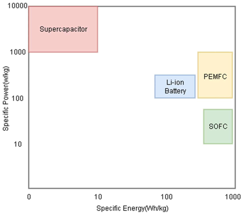
Figure 2.
Schematic Diagram of a PEMFC Stack Architecture.
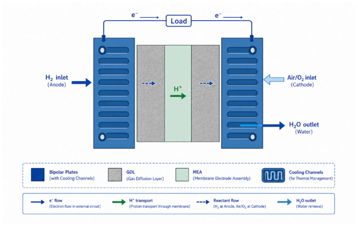
Figure 3.
PEMFC Polarization and Power Density Curves.
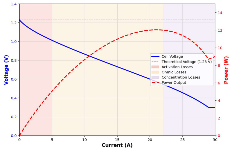
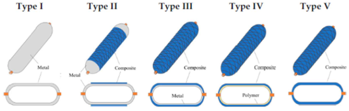
Figure 5.
Potential craks in the composite walls of the hydrogen tanks under high pressure [33].
Figure 5.
Potential craks in the composite walls of the hydrogen tanks under high pressure [33].
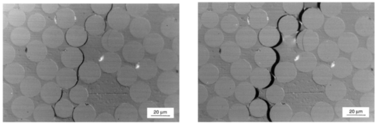

Figure 7.
Integrated high pressure hydrogen gaseous tanks in the aerial vehicles applications [36,40].
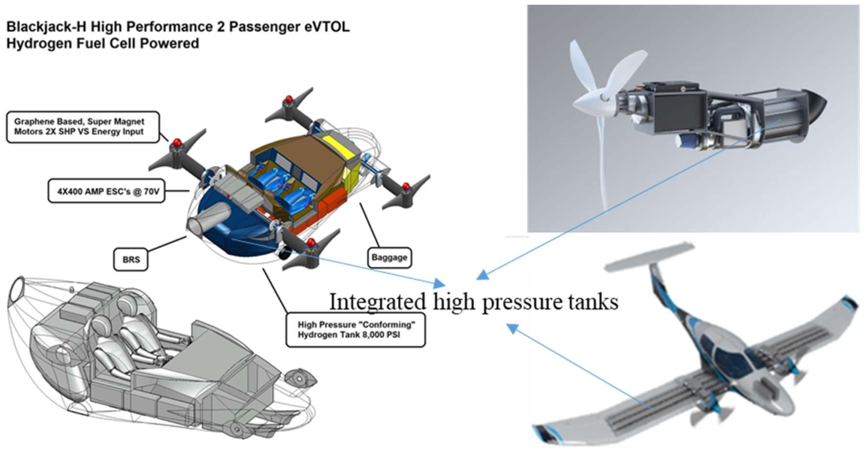
Figure 8.
Comparison of Hydrogen Storage Methods: Gravimetric vs. Volumetric Energy Density.
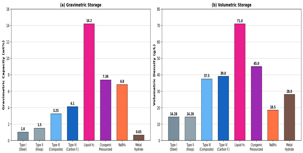
Figure 9.
UAV Power Profile Throughout a Typical Flight — Fuel Cell and Battery Contributions.
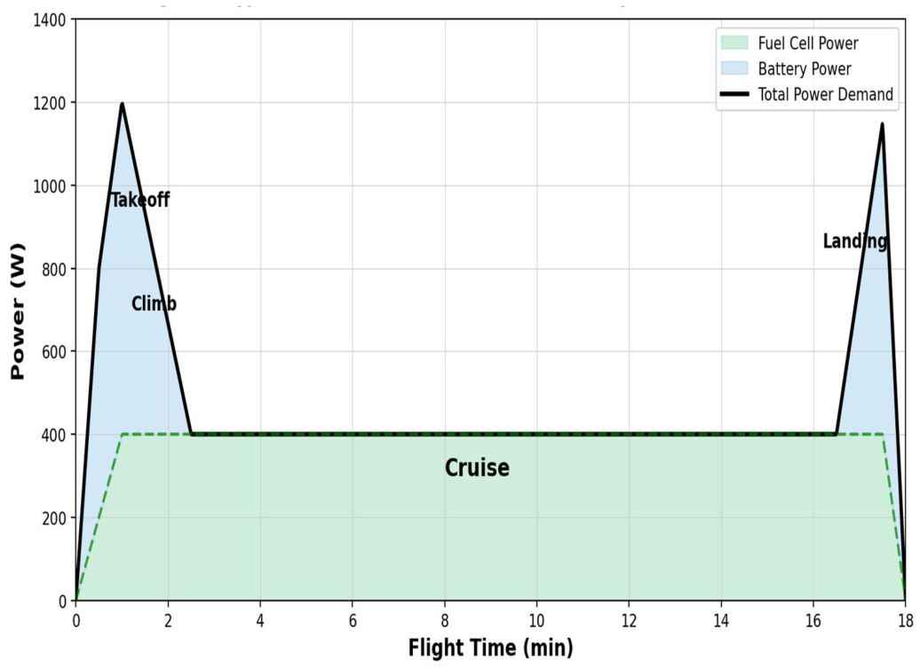
Figure 10.
Hybrid Power System Topologies: Parallel, Series, and FC–Supercapacitor Configurations.
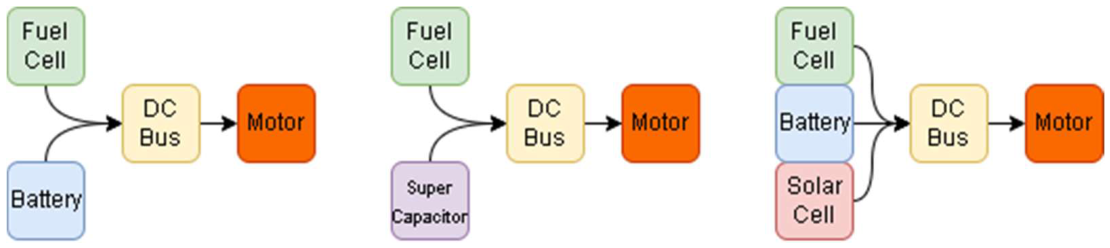
Figure 11.
Flight Endurance of Commercial H₂ UAV Platforms.
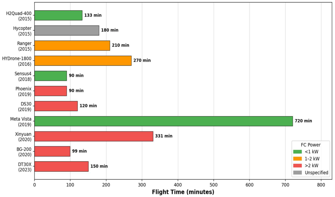
Table 1.
UAV Classification and Power Requirements.
| UAV CATEGORY | MTOW (KG) | RANGE | ALTITUDE | ENDURANCE | FC SUITABILITY |
|---|---|---|---|---|---|
| NANO/MICRO | <0.1 | <1 km | <300 m | <1 h | LOW (WEIGHT CONSTRAINT) |
| MINI | 0.1–2 | 1–10 km | <300 m | 1–4 h | SUITABLE (COMPACT FC) |
| TACTICAL | 2–150 | 10–200 km | <3,000 m | 4–24 h | HIGH (LONG-DURATION MISSIONS) |
| STRATEGIC/MALE | 150–600 | >200 km | <9,000 m | >24 h | VERY HIGH (HALE) |
| LARGE-SCALE HALE | >600 | GLOBAL | >15,000 M | >24 H | UNDER INVESTIGATION |
Table 2.
Fuel Cell Types: Technical Specifications and UAV Suitability Comparison.
| FC Type | Electrolyte | Temp. | Power Density (W/kg) | Eff. (%) | TRL (UAV) | Key Advantage | Principal UAV Barrier |
|---|---|---|---|---|---|---|---|
| PEMFC | Nafion membrane | 60–80 °C | 400–700 | 50–60 | 7–8 | Fast cold-start, low temperature | Membrane humidification |
| SOFC | Ceramic oxide | 700–1000 °C | 100–300 | 55–65 | 3–4 | High efficiency, fuel flexibility | 20–60 min thermal start-up, vibration |
| DMFC | Polymer membrane | 20–90 °C | 100–200 | 20–30 | 5–6 | Liquid fuel, simple storage | Low power density, methanol crossover |
| AFC | KOH solution | 60–90 °C | 200–400 | 60–70 | 4–5 | High efficiency | CO₂ poisoning, electrolyte management |
| PAFC | Phosphoric acid | 150–200 °C | 80–150 | 40–50 | 3–4 | CO-tolerant | High mass, high operating temperature |
Table 3.
Unified Hydrogen UAV Design Framework: Mission Profile to System Configuration Mapping.
| Mission Profile | MTOW / Endurance | Storage Technology | Hybrid Topology | EMS Strategy |
|---|---|---|---|---|
| Short-range ISR / delivery | < 5 kg / < 1 h | Type III CGH₂ (350 bar) | Parallel passive | Rule-based threshold |
| Tactical reconnaissance | 5–25 kg / 1–4 h | Type IV CGH₂ (700 bar) | Parallel active (DC-DC) | Fuzzy logic / MPC |
| Medium endurance survey | 10–50 kg / 4–8 h | Type IV CGH₂ or NaBH₄ | Series or active parallel | Model predictive control |
| MALE (> 8 h) | 25–150 kg / 8–24 h | Type IV CGH₂ or LH₂ (cryo) | FC-supercapacitor hybrid | Deep Learning EMS |
| HALE (> 24 h) | > 150 kg / > 24 h | LH₂ cryogenic storage | Regenerative / triple hybrid | Hierarchical RL-based EMS |
| eVTOL / UAM | Per aircraft spec | Type IV CGH₂ + battery pack | FC-battery parallel active | Certifiable rule-based + MPC |
| Rotary-wing multi-rotor | 2–25 kg / 0.5–2 h | Type III or IV CGH₂ | Parallel passive or FC-SC | Rule-based with SOC window |
Note: CGH₂ = compressed gaseous hydrogen; LH₂ = liquid hydrogen; NaBH₄ = sodium borohydride; MPC = model predictive control; RL = reinforcement learning; SC = supercapacitor; MALE = medium altitude long endurance; HALE = high altitude long endurance. MTOW thresholds are indicative; actual selection depends on propulsion architecture and payload fraction.
Table 4.
Comparative Analysis of Energy Management Strategies.
| EMS Strategy | Method | Comp. Load | Fuel Saving | Real-Time | Certification Barrier | Applications |
|---|---|---|---|---|---|---|
| Rule-based | Threshold values | Very low | Low | Yes | Low | Embedded systems |
| State machine | Predefined transitions | Low | Moderate | Yes | Low | Commercial UAV systems |
| Fuzzy logic | Fuzzy rule base | Moderate | Moderate–High | Yes | Moderate | Uncertain operating conditions |
| Model Predictive Control | Optimization | High | High | Limited | High | Predictive mission planning |
| Deep Learning / RL | Neural network | Very high | Highest | Research stage | Very high | Intelligent autonomous systems |
Table 5.
Key Standards and Regulations Applicable to Hydrogen Fuel Cell UAV Systems.
| Standard | Body | Scope | Status | FC UAV Relevance |
|---|---|---|---|---|
| IEC 62282 | IEC | Fuel cell safety | In force | Fundamental safety requirements |
| SAE AS6858 | SAE International | Aircraft fuel cells | In force | Aviation-specific provisions |
| FAA AC 21-17G | FAA | Validation of Foreign Airworthiness Approvals | In force | Airworthiness Validation |
| EASA CS-UAS | EASA | UAS categories | In force | European certification framework |
| ISO/IEC 14687 | ISO/IEC | H₂ fuel quality | In force | Purity requirements for PEMFC |
| UN GTR No.13 | UNECE | H₂ vehicle safety | In force | Storage and leak standards |
Table 7.
Technology Readiness Level Targets for Hydrogen UAV System Domains (2025–2035).
| Technology Domain | Sub-component | TRL 2025 (Current) |
Target 2027 | Target 2030 | Target 2035 |
|---|---|---|---|---|---|
| PEMFC Stack | Sub-2 kW UAV-specific lightweight stack | 6–7 | 7–8 | 8–9 | 9 (certified) |
| H₂ Storage | Type IV 700 bar UAV-qualified (< 5 kg tank) | 5–6 | 6–7 | 8 | 9 (airworthy) |
| EMS | AI-based EMS with certifiable means of compliance | 3–4 | 4–5 | 6–7 | 8 (EASA AMC) |
| Cold-Start | Reliable cold-start at −40 °C without external heating | 2–3 | 3–4 | 5–6 | 7–8 |
| Infrastructure | UAV-specific H₂ refueling at vertiport/airfield | 3–4 | 5 | 7 | 8–9 |
Table 8.
Key Technical, Operational, and Economic Targets for Hydrogen-Powered UAVs (2030–2035).
| Challenge | Target (2030) | Target (2035) |
|---|---|---|
| PEMFC stack cost | < USD 300/kW | < USD 100/kW |
| Type IV tank cycle life | > 5,000 fill cycles at 70 MPa | > 10,000 cycles with in-service monitoring |
| Cold-start temperature | −30 °C demonstrated | −40 °C certified |
| AI-EMS certification | First means of compliance established | Production deployment in > 5 commercial platforms |
| Green H₂ cost (UAV market) | < USD 3.5/kg | < USD 2/kg |
| Multi-rotor endurance (< 25 kg) | > 8 hours demonstrated | > 12 hours commercial |
Disclaimer/Publisher’s Note: The statements, opinions and data contained in all publications are solely those of the individual author(s) and contributor(s) and not of MDPI and/or the editor(s). MDPI and/or the editor(s) disclaim responsibility for any injury to people or property resulting from any ideas, methods, instructions or products referred to in the content. |
© 2026 by the authors. Licensee MDPI, Basel, Switzerland. This article is an open access article distributed under the terms and conditions of the Creative Commons Attribution (CC BY) license (http://creativecommons.org/licenses/by/4.0/).
Copyright: This open access article is published under a Creative Commons CC BY 4.0 license, which permit the free download, distribution, and reuse, provided that the author and preprint are cited in any reuse.


