

Submitted:
10 August 2026
Posted:
11 August 2026
You are already at the latest version
Abstract
To comprehensively improve vehicle ride comfort and handling stability, as well as to enhance the robustness and disturbance rejection capability of the suspension system under uncertain operating conditions, this paper first establishes a full vehicle suspension dynamic model. On this basis, an improved SH-ADD controlled suspension is proposed as a reference model through the analysis of power flow characteristics within the suspension system, and a sliding mode control (SMC) strategy is subsequently designed based on this reference model. Simulation results indicate that, compared with conventional control strategies, the proposed algorithm offers a clear advantage in reducing the root mean square (RMS) values of sprung mass acceleration, thereby effectively suppressing body vibration and improving ride comfort. In addition, both roll and pitch angular accelerations are notably reduced, contributing to enhanced body attitude stability. Moreover, when subjected to parameter uncertainties such as variations in vehicle speed and sprung mass, the proposed controller maintains excellent robustness and stable control performance, demonstrating its overall effectiveness in improving suspension system performance under complex operating conditions.
Keywords:
smoothness
; power-flow analysis
; improved SH-ADD control strategy
; sliding mode control strategy
1. introduction
The automotive industry is undergoing rapid and unprecedented development. Evolving from purely mechanical systems, it has progressively advanced toward electrification, intelligence, and connectivity, and has now become an integrated system encompassing multiple disciplines, including mechanical engineering, electronics, and information technology. People’s expectations of automobiles have long transcended basic transportation functions; increasingly stringent demands are placed on vehicle performance, with the desire to achieve both superior ride comfort and smooth driving experience during operation [1]. The suspension system is a critical component of the vehicle chassis, primarily serving to reduce body vibrations and improve ride safety and comfort [2]. Based on their operating principles, suspension systems can be categorized as passive, semi-active, and active suspensions [3]. Conventional passive suspensions cannot adequately meet the ride comfort requirements under varying operating conditions, whereas active suspensions are difficult to promote for practical applications due to their high cost and significant energy consumption. Semi-active suspensions, which achieve satisfactory vibration attenuation by adjusting the damping coefficient of the damper, can effectively improve ride comfort at a relatively low implementation cost. Consequently, they have attracted considerable attention from researchers worldwide [4,5,6]. Therefore, the development and application of control algorithms for semi-active suspensions have become a crucial aspect of semi-active suspension design.
Since the 1990s, extensive research has been conducted by scholars worldwide on control algorithms for semi-active suspensions. To date, significant progress has been achieved in the theory and algorithms of semi-active suspension control, and a variety of control strategies have been proposed. These include classical control theory-based approaches, such as SH control [7,8] and ADD control [9]; modern control theory-based approaches, such as sliding mode control (SMC) [10]; and intelligent control theory-based approaches, such as neural network control [11,12,13] and fuzzy control [14,15].
However, when confronted with complex road conditions, a single suspension control strategy alone often fails to achieve optimal control performance and cannot fully satisfy the requirements of ride comfort and handling stability. For instance, the SH control algorithm exhibits favorable vibration attenuation in the low-frequency range, but its performance deteriorates in the mid-to-high frequency range. In contrast, the ADD control algorithm shows the opposite trend, performing well in the mid-to-high frequency range while its effectiveness in the low-frequency range is even inferior to that of a passive suspension. Therefore, combining two or more control theories to complement each other’s strengths and circumvent their weaknesses can yield superior overall performance. For example, Wang, et al. [16] proposed a fuzzy sliding mode control method based on an optimized reaching law to address the ride comfort and stability issues of vehicle semi-active suspensions. By establishing a quarter-vehicle semi-active suspension model, they designed a tracking error model and a sliding mode controller. Combined with an optimized saturation function reaching law and a fuzzy control strategy, the proposed method improves the control accuracy and robustness of the system, effectively alleviates vehicle vibration, enhances ride comfort, and exhibits strong adaptability to various road conditions and vehicle speeds. Wang Yue [17] observed that the conventional on-off skyhook control and the LQR method perform well in the low-frequency and high-frequency ranges, respectively, exhibiting complementary characteristics. Accordingly, he proposed a frequency-division combined control approach, namely the SH-LQR hybrid control strategy. Simulation results demonstrate that the semi-active suspension employing SH-LQR control achieves favorable vibration attenuation performance.Li, et al. [18]proposed a fuzzy sliding mode control (FSMC) strategy for semi-active air suspension systems based on magnetorheological (MR) dampers. To address the uncertainties inherent in the air suspension system, fuzzy control is employed to adjust the boundary layer of the sliding mode controller, thereby effectively suppressing the adverse effects of chattering on control accuracy and ensuring system stability. Simulation results demonstrate that the FSMC strategy enables the MR damper used in the semi-active air suspension to achieve superior vibration attenuation performance and ride comfort. Phu, et al. [19] introduced a novel composite adaptive controller based on neural networks and a prescribed sliding surface. This controller achieves excellent vibration control performance with small tracking errors relative to the preset targets. Compared with conventional sliding mode controllers that employ only a single sliding surface and proportional-integral-derivative (PID) controllers, the proposed controller demonstrates superior control performance. Guo Konghui [20] analyzed the SH and ADD control algorithms from the perspective of phase characteristics, identifying their respective advantages and disadvantages. By combining the strengths of both approaches and employing phase compensation techniques, he proposed an improved acceleration-driven damping control. The effectiveness of the proposed control scheme was verified through Simulink simulations and hardware-in-the-loop (HIL) tests, covering both the time and frequency domains.
Single control strategies have inherent limitations in suspension systems. Thus, mathematical models for random and bump road excitations are first established. Taking the full-vehicle suspension as the object, the advantages and drawbacks of SH and ADD algorithms are analyzed from energy transfer and conversion perspectives. On this basis, an improved SH-ADD control strategy is proposed. To enhance robustness and disturbance rejection, the improved model is adopted as a reference model, and accordingly a sliding mode control (SMC) strategy is designed. Through simulation tests, ride comfort and handling stability are comprehensively evaluated, and the results confirm the effectiveness of the proposed strategy. The main contributions are twofold: first, the improved strategy re-derives the switching threshold via power flow theory, which improves switching accuracy; second, SMC is introduced to effectively track the reference model, thereby coping with parameter uncertainties and external disturbances.
2. Establishment of the Full-Vehicle Model
2.1. Randomized Pavement Model
For road roughness measurement, a precision level is employed to collect a substantial amount of profile data. The measured roughness profile is subsequently modeled as a Gaussian stochastic process, and the amplitude data are transformed into white noise via appropriate filtering. From the processed results, key statistical characteristics—including the power spectral density and the variance —are extracted, where is defined by Equation (1) [21,22]:
where is the road roughness coefficient; is the frequency index, typically set as ; is the spatial frequency; and represents the reference spatial frequency.a Class D road profile according to ISO 8608 is adopted for the random excitation scenarios, with the corresponding roughness coefficient set to .
For the four-wheel road excitation inputs, the following assumptions are adopted: (i) the road profiles under the left and right wheels are assumed to be identical, i.e., the left and right wheel tracks are considered perfectly correlated, as the vehicle is simulated under straight-line driving conditions; (ii) the rear wheels are subjected to the same road profile as the front wheels but with a time delay, which accounts for the wheelbase effect. Specifically, the road excitation at the rear wheels is obtained by delaying the front wheel input by , where and are the distances from the vehicle center of gravity to the front and rear axles, respectively, and is the vehicle forward speed. This time-delayed excitation model ensures that the front and rear wheels experience the same road roughness sequence with the appropriate phase lag, reflecting the spatial separation between the axles.
2.2. Modeling of Impact Road Surfaces
2.2.1. Modeling of Bump Road Model
During vehicle operation, bump road surfaces such as speed bumps and manhole covers are frequently encountered, which tend to induce severe vibration impacts on the vehicle and consequently degrade ride comfort. To better validate the damping performance of the suspension system under such bump excitations, this paper establishes a bump road model using a cosine function. The input expression of the model is given as follows [23]:
Among them, is the convex hull pavement height, ; is the vehicle speed, ; is the convex hull pavement width, .
2.2.2. Hump Pavement Model
Potholes or ruts are another common type of impulsive road excitation, which can be characterized and described by an inverted triangular model and a piecewise function. The input expression of the model is given as follows [24]:
where is the distance from the vehicle’s starting point to the left edge of the pothole, .; is the length of the bottom edge of the pothole, ; is the vertical height of the pothole cross-section, ; and is the vehicle speed, .
2.3. Whole Vehicle Suspension Model
The suspension serves as a critical connecting component between the vehicle body and the tires. Its core function is to efficiently transmit the dynamic and static loads generated between them. During vehicle operation, it effectively suppresses bumps and vibrations, thereby improving ride comfort and ensuring stable driving under various road conditions. The full-vehicle suspension model is established to characterize the suspension dynamics in terms of vertical, pitch, and roll motions of the vehicle body, together with the vertical motions of the four unsprung wheels. This yields a total of 7 degrees of freedom (DOFs): 3 DOFs for the sprung mass (vertical, pitch, roll) and 4 DOFs for the unsprung masses (vertical displacement of each wheel), as shown in Figure 1[25,26,27].
Based on Newton’s second law and vehicle dynamics theory, the dynamic equations of the full-vehicle suspension model are derived and given as follows.
(1)The vertical dynamic equation of the sprung mass is:
(2)The pitch dynamic equation of the vehicle body is:
(3)The roll dynamic equation of the vehicle body is:
(4)The vertical dynamic equation of the unsprung mass is:
Among them, represents the sprung mass at the center of mass of the vehicle body, represents the vertical displacement of the sprung mass, represents the vehicle roll angle acceleration, represents the vehicle pitch angle acceleration, and respectively represent the longitudinal distances from the center of mass to the front axle and the rear axle, and respectively represent the front track width and rear track width, 、、 and respectively represent the vertical displacements of the sprung mass for the left-front, right-front, left-rear, and right-rear independent suspensions, 、、 and respectively represent the suspension stiffness of the left-front, right-front, left-rear, and right-rear wheels, 、、 and respectively represent the damping coefficients of the left-front, right-front, left-rear, and right-rear dampers, 、、 and respectively represent the unsprung mass of the left-front, right-front, left-rear, and right-rear wheels, 、、 and respectively represent the vertical displacements of the left-front, right-front, left-rear, and right-rear tires, 、、and respectively represent the tire stiffness of the left-front, right-front, left-rear, and right-rear wheels, 、、and respectively represent the road excitation inputs for the left-front, right-front, left-rear, and right-rear wheels.
Assuming the vehicle body is a rigid body and its pitch and roll angles during motion are small, it can be approximated that ,,. Based on rigid body kinematics, the relationship between the vertical displacements of the sprung mass at the four independent suspension points (、、), the vertical displacement of the sprung mass at the vehicle’s center of mass (), the roll angle (), and the pitch angle () can be derived as follows:
The parameters of the full vehicle suspension model selected in this paper are listed in Table 1.
3. Sliding Mode Control Algorithm Based on Reference Model
3.1. Introduction to Conventional Control Algorithms
3.1.1. Sh Control Algorithm
The core idea of the SH control algorithm is to assume the existence of an imaginary “skyhook” that is absolutely stationary and connected to the vehicle body, thereby suppressing vibrations of the sprung mass caused by road excitations. However, since an absolutely stationary “skyhook” cannot exist in reality, an adjustable damper is added to the suspension system to approximate the effect of the skyhook concept. Building on this, Sammier, et al. [28] proposed an improved linear skyhook control method, which can linearly adjust the damping range based on the vehicle body’s vibration velocity. For linear SH control, the control strategy is as follows:
Among them, is the closed—loop control coefficient. When , this control law is equivalent to the switch—type SH control; and represent the vertical displacements of the unsprung mass and the sprung mass, respectively; is the relative velocity of the suspension, defined as ; and denote the minimum and maximum adjustable damping coefficients of the damper, respectively.
3.1.2. Add Control Algorithm
The core idea of the ADD control algorithm [29] is to assume the existence of an “ideal inerter.” This ideal inerter is used to reduce the vertical acceleration of the vehicle body, making its motion more stable and improving both ride comfort and passenger comfort. For linear ADD control, the control strategy is as follows:
Among them, represents the ideal inerter coefficient.
3.1.3. Sh-Add Control Algorithm
For both SH and ADD control algorithms, Savaresi and Spelta [30] conducted in depth research. By analyzing their advantages, disadvantages, and limitations, they proposed a composite control algorithm: the Mixed Skyhook-Acceleration-Driven Damper (SH-ADD) control algorithm. This approach combines the strengths of both SH and ADD control to reduce vehicle vibration acceleration across the full frequency range. The control strategy is as follows:
Among them, represents the crossover frequency between the SH control algorithm and the ADD control algorithm. Thus, can be regarded as a simple “frequency selector,” enabling the selection of the SH control algorithm for suspension control in the low frequency range and the ADD control algorithm in the high frequency range. This ensures that the suspension system achieves effective vibration reduction across the entire frequency domain.
3.2. Ideal Model Establishment
When road excitations fall within the low—frequency range, particularly near the body resonance frequency, the SH control algorithm effectively reduces the vehicle’s sprung mass acceleration, thereby significantly improving ride comfort. Conversely, in the mid—to—high frequency range, especially near the wheel resonance frequency, the ADD control algorithm demonstrates more pronounced vibration damping effects compared to the SH control algorithm.
From the perspective of energy transfer and transformation in the suspension system, the underlying control theories of the SH and ADD control algorithms can be deeply analyzed: The core principle of the SH control algorithm is to dynamically adjust the damper damping to absorb as much energy as possible generated by the vibration of the sprung mass, thereby achieving vibration reduction. The ADD control algorithm, on the other hand, focuses on skillfully altering the damper damping to block the transfer of vibration energy from the unsprung mass to the sprung mass, ensuring driving stability. The ideal control model of the improved SH-ADD control suspension system is shown in Figure 2.
As shown in Figure 2, the improved SH-ADD controlled suspension model is used as a reference model, and the dynamic equation is established as:
Among them, and represent the unsprung mass and sprung mass, respectively; denotes the road excitation; and are the suspension stiffness and tire stiffness, respectively; is the output damping coefficient of the improved SH-ADD control strategy.
According to the law of conservation of mechanical energy, the total mechanical energy of the vehicle model is the sum of its total kinetic energy and total potential energy:
Among them, is the total mechanical energy; is the total kinetic energy; is the total potential energy.
In the model, the total kinetic energy is the sum of the kinetic energies of the unsprung mass and the sprung mass:
In the modeling of tire characteristics, only its vertical stiffness Kt is considered, while its damping effect is neglected. Consequently, the tire acts as a purely elastic energy storage element rather than an energy dissipating component. In the subsequent power-flow analysis, we focus exclusively on the energy dissipated by the damper, as the tire’s role is limited to temporary energy storage. Under this assumption, the total elastic potential energy stored in the suspension system can be expressed as:
Since the tire is regarded as a rigid component and its elastic deformation is neglected, the shock absorber serves as the sole energy—dissipating component. By adjusting its own damping coefficient, it converts mechanical energy generated by vibrations into heat energy and dissipates it. Thus, the power absorbed by the shock absorber can be expressed as:
The power dissipated by the shock absorber can be expressed as:
When the power absorbed by the shock absorber exceeds the power it dissipates, i.e., , it indicates that the shock absorber has a significant advantage in energy absorption. In this scenario, applying the SH control algorithm can effectively utilize the energy-absorbing characteristics of the shock absorber to achieve excellent vibration damping, thereby significantly improving vehicle ride comfort. Conversely, if the power absorbed by the shock absorber is less than the power dissipated, i.e., , it suggests that energy dissipation dominates. In this case, the ADD control algorithm can be employed to effectively block energy transfer, isolating the energy interaction between the sprung and unsprung masses, thus also achieving effective vibration damping and ensuring ride comfort. Combining Equations (22) and (23), we obtain:
Therefore, the sign (positive or negative) of depends on . Based on the analysis of suspension power flow and transfer, the control strategy law of the improved SH-ADD control algorithm (improved SH-ADD Control Strategy) is derived as follows:
By analyzing the established control law, the following conclusions can be drawn:When the squared difference between the velocity of the sprung mass (i.e., the mass above the suspension) and the velocity of the unsprung mass (i.e., the mass below the suspension) is non-negative, i.e., , the SH control algorithm is adopted to adjust the damping coefficient of the suspension. This effectively regulates the variation of the damping coefficient, thereby achieving excellent vibration damping performance.Conversely, when the squared difference is negative, i.e., , the ADD control algorithm is employed to adjust the suspension damping coefficient, further optimizing the vibration damping effect of the suspension system. By combining the advantages of both algorithms, the vehicle’s ride comfort is enhanced across the full frequency domain.
It is worth noting that, unlike the conventional SH-ADD rule (Eq. (17)) where the switching threshold is defined as with being a tunable weighting coefficient, the proposed criterion in Eq. (25) is derived directly from power-flow balance. While the choice of α significantly affects the control performance, its optimal value varies with vehicle parameters such as sprung mass and suspension stiffness, which limits the robustness of the conventional approach. In contrast, the proposed switching criterion eliminates the need for empirical tuning of α, offering a physically interpretable threshold that adapts naturally to changes in vehicle dynamics.
3.3. Design of Sliding Mode Controller
The objective of the reference model—based sliding mode control algorithm is to regulate the damping force of the shock absorber, ensuring that the vehicle’s vibration response induced by road roughness tracks the vibration response of the improved SH-ADD control reference model. This approach not only enhances ride comfort and handling stability but also improves the robustness and disturbance resistance of the control system.
Therefore, considering the error between the desired output and the actual output of the reference model, the error is defined as:
Among them, is the actual output of the sprung mass displacement, and is the sprung mass displacement of the reference model.
Then, the first derivative of the error is:
Then, the second derivative of the error is:
From Eqs. (26)、(27) and (28), a higher-order sliding surface can be constructed as:
Among them, , is the sliding surface parameter.
In order to effectively suppress the chattering phenomenon of the system, high-intensity control actions are adopted when the system is far from the sliding surface to quickly steer the system state toward the sliding surface. As the error gradually decreases, the control intensity is smoothly reduced to achieve a smooth transition, ensuring both rapidity and stability in the system control process. This paper introduces an error-driven adaptive boundary layer thickness defined as:
The boundary layer thickness is adaptively adjusted with an initial value of and a lower bound of the same value, i.e., . The adaptation factor is set to .
To avoid control oscillations caused by frequent damping switching, this paper employs the hyperbolic tangent function (tanh), which is continuous and differentiable, as the saturation function:
Moreover, to ensure the system provides greater control force when the error is large and automatically reduces the gain when the error is small, the control gain in this paper is designed as a function of the magnitude of the sliding surface:
Based on the above analysis, the control law is formulated as follows:
where is a small positive constant set to , introduced to avoid singularity in the SMC control law without affecting the steady-state accuracy
To verify the stability of the control law, a standard Lyapunov function is selected:
Its derivative with respect to time is:
where represents the lumped external disturbance and model uncertainties, which is assumed to be bounded by . Since satisfies for all , the first term in Eq. (35) is always negative. Furthermore, the term is strictly negative for all . Consequently, the following inequality holds:
For the case where , we have . This leads to:
Therefore, a sufficient condition for is:
When this condition is satisfied, the reaching condition holds for all . This ensures that the system trajectory is driven toward the sliding surface in finite time and subsequently maintained within the boundary layer . The negative term further enhances the convergence rate and provides additional robustness against disturbances.
It is worth noting that the conditio is a conservative sufficient condition. In practice, the dynamic gain adapts according to Eq. (32), which provides larger gain when the system is far from the sliding surface (large) and automatically reduces gain near the surface to mitigate chattering, thus striking a balance between robustness and control smoothness.
4. Simulation Analysis
Building upon the model-reference-based sliding mode control strategy for the semi-active suspension designed earlier, this chapter further conducts an in-depth and systematic investigation by integrating the established full-vehicle suspension model, stochastic road excitation model, and impact road profile model. A comprehensive simulation study and performance evaluation are carried out by comparing the passive suspension, the SH-ADD strategy, the PID control algorithm of the reference model, and the proposed sliding mode control strategy (SMC)for the semi-active suspension. The analysis focuses particularly on its control effectiveness and robustness under complex driving conditions and in the presence of model parameter uncertainties.
4.1. Analysis of Smc Control Performance Under Randomized Pavement Excitation
Using the random road model established in the preceding section, time-domain simulations are conducted under a Class D road profile at a vehicle speed of 20 m/s. The simulation duration is set to 20 s with a fixed time step of 0.001 s. The time histories of the sprung mass acceleration, roll angular acceleration, and pitch angular acceleration are recorded for the passive suspension, PID controller, the SH-ADD strategy, and the proposed SMC strategy. The root mean square (RMS) values of these responses are then computed over the entire simulation period. To evaluate the control performance, the RMS variations of the SH-ADD, PID, and SMC strategies relative to the passive suspension are quantified, where negative values indicate improvement and positive values indicate deterioration.
As shown in Figure 3, compared with the passive suspension, the PID control strategy leads to instantaneous increases in sprung mass acceleration, roll angular acceleration, and pitch angular acceleration to varying degrees at certain time instants. The SH-ADD control strategy achieves better performance than the PID controller in terms of peak reduction and overall response suppression, demonstrating its effectiveness in improving ride comfort. In terms of sprung mass acceleration, the reference model based sliding mode control strategy for the semi-active suspension can effectively reduce the peak values and keep the acceleration essentially stable within a reasonable range, thereby ensuring ride comfort during vehicle operation. Regarding vehicle roll angular acceleration, the SH-ADD strategy provides noticeable attenuation of the roll response compared with the PID control, while the proposed SMC strategy achieves the lowest peak values overall, effectively suppressing the rolling tendency of the vehicle. Similarly, for pitch angular acceleration, the SH-ADD control also yields improved performance over the PID controller, and the proposed SMC strategy attains the lowest peak values in general, effectively mitigating the pitching tendency and further improving the dynamic performance of the vehicle during driving.
As shown in Table 2, the root mean square (RMS) values of the sprung mass acceleration, vehicle roll angular acceleration. For sprung mass acceleration, all three control strategies achieve reductions to varying degrees. The PID control yields a reduction of 0.64%, while the SH-ADD strategy achieves a reduction of 18.26%. The proposed SMC attains the most significant reduction of 21.64%, demonstrating superior vibration suppression performance.Regarding roll angular acceleration, the PID control, SH-ADD, and SMC achieve reductions of 3.61%, 9.14%, and 9.90%, respectively. All three strategies effectively suppress the vehicle’s roll motion, with the SMC showing the best performance.For pitch angular acceleration, the PID control leads to a deterioration of 5.06%, whereas the SH-ADD and SMC strategies achieve reductions of 11.67% and 13.87%, respectively.
Based on the results summarized in Table 2, the proposed SMC strategy consistently outperforms both the PID and SH-ADD controllers across all three metrics. It not only reduces the sprung mass acceleration to enhance ride comfort, but also attenuates the roll and pitch angular accelerations, thereby maintaining favorable vehicle body posture during operation.
4.2. Performance Analysis of Smc Under Impact Road Excitation
Using the impact road model established in the preceding section, simulations are conducted for a vehicle traversing pothole and bump roads at a speed of 5 m/s. The simulation duration is set to 10 s with a fixed time step of 0.001 s. The transient responses of the sprung mass acceleration, roll angular acceleration, and pitch angular acceleration are obtained for four configurations: passive suspension, PID control, SH-ADD control, and the proposed SMC strategy. The RMS values of these accelerations and the settling times are then calculated. The performance changes relative to the passive suspension are quantified, where negative values indicate improvement and positive values indicate deterioration.
4.2.1. Simulation and Analysis of Pothole Road
As shown in Figure 4, compared with the passive suspension, the SH-ADD and PID controllers achieve certain peak reductions in all three acceleration responses. However, their oscillations decay slowly, and the transient responses persist for a relatively long duration.In contrast, the proposed SMC strategy, while not always yielding the lowest peak values, exhibits a significantly faster attenuation rate. The accelerations under SMC decay rapidly to their steady-state values within a short period. This quick stabilization effectively improves ride comfort and enhances vehicle dynamic performance.
As shown in Table 3, for sprung mass acceleration, the SH-ADD control achieves a slight reduction of 0.76% compared with the passive suspension. The PID control leads to a deterioration of 8.89%, whereas the proposed SMC strategy yields a reduction of 6.68%, demonstrating its superior vertical vibration suppression capability.Regarding roll angular acceleration, the SH-ADD strategy results in a reduction of 4.51%. The SMC strategy achieves the most significant improvement with a reduction of 10.40%. In contrast, the PID control increases the roll acceleration by 16.03%, adversely affecting the vehicle’s roll attitude.For pitch angular acceleration, the SH-ADD and SMC strategies achieve reductions of 11.81% and 5.38%, respectively. The PID control, however, leads to a slight increase of 2.66%.
Overall, the proposed SMC strategy outperforms both the SH-ADD and PID controllers, yielding the most balanced improvements across all three metrics under potholed road conditions.
Table 4 compares the settling times of the four control strategies under potholed road excitation.For sprung mass acceleration, the passive suspension has a settling time of 4.27 s. The SH-ADD and PID controllers reduce this to 3.24 s and 4.37 s, corresponding to improvements of 24.26% and –2.25%, respectively. The proposed SMC strategy achieves the shortest settling time of 3.15 s, which is 26.15% shorter than that of the passive suspension. This indicates that the SMC strategy can more quickly suppress sprung mass vibrations and restore the vehicle to a stable ride condition.For roll angular acceleration, the settling times of the passive suspension, SH-ADD, PID, and SMC are 4.24 s, 3.63 s, 2.69 s, and 3.14 s, respectively. The PID controller yields the largest reduction of 36.73%, while the SH-ADD and SMC strategies achieve reductions of 14.37% and 26.04%.For pitch angular acceleration, the settling times of the passive suspension, SH-ADD, PID, and SMC are 3.84 s, 3.61 s, 3.93 s, and 3.11 s, respectively. The SMC strategy achieves the shortest settling time, with a reduction of 18.96% compared with the passive suspension.Overall, the proposed SMC strategy demonstrates the most balanced and effective performance in reducing settling times across all three acceleration responses.
4.2.2. Simulation and Analysis of Bump Road
As shown in Figure 5, compared with the passive suspension, SH-ADD, and PID control, the sliding mode control (SMC) strategy based on the reference model has a significant advantage in deceleration rate. After being disturbed, SMC can make the sprung mass acceleration, roll angle acceleration, and pitch angle acceleration converge to the steady-state value more quickly. This rapid attenuation significantly reduces the vibration and swaying of the vehicle during operation, thereby effectively improving the ride comfort. In addition, this control strategy can promptly suppress the transient response of the vehicle body. This helps maintain the vehicle’s smoothness and ensures its smooth operation under various road conditions.
Table 5 presents the RMS values of the sprung mass acceleration, roll angular acceleration, and pitch angular acceleration for the four suspension configurations under bump road excitation.For sprung mass acceleration, the SH-ADD strategy yields a marginal increase of 0.53% compared with the passive suspension. The PID controller leads to a significant deterioration of 36.68%, while the proposed SMC strategy achieves a reduction of 5.07%.Regarding roll angular acceleration, the SH-ADD strategy results in an increase of 3.41%. The PID controller exhibits the poorest performance with an increase of 35.88%. In contrast, the SMC strategy achieves a reduction of 4.38%.For pitch angular acceleration, the SH-ADD and SMC strategies achieve reductions of 6.36% and 9.17%, respectively. The PID controller, however, increases this metric by 20.84%.
Table 6 summarizes the settling times of the four suspension configurations under bump road excitation.For sprung mass acceleration, the passive suspension has a settling time of 3.36 s. The SH-ADD and SMC strategies achieve reductions of 31.07% and 21.25%, with settling times of 2.32 s and 2.65 s, respectively. In contrast, the PID controller increases the settling time by 33.10%, reaching 4.47 s.For roll angular acceleration, the settling times of the passive suspension, SH-ADD, PID, and SMC are 3.33 s, 2.71 s, 4.40 s, and 2.24 s, respectively. The SH-ADD and SMC strategies achieve reductions of 18.51% and 32.81%, while the PID controller results in a deterioration of 32.09%.For pitch angular acceleration, the settling times of the passive suspension, SH-ADD, PID, and SMC are 2.92 s, 2.69 s, 4.02 s, and 2.21 s, respectively. The SH-ADD and SMC strategies yield reductions of 7.87% and 24.28%, whereas the PID controller increases the settling time by 37.41%.
In summary, when the vehicle is subjected to impact road excitations, the proposed SMC strategy demonstrates clear advantages over the passive suspension, SH-ADD, and PID controllers.Compared with the passive suspension, the SH-ADD strategy provides moderate improvements in RMS reductions and settling times. The PID controller, however, often leads to degraded performance under impact conditions.The proposed SMC strategy effectively reduces the RMS values of sprung mass acceleration, roll angular acceleration, and pitch angular acceleration. It also suppresses vehicle body vibration and attitude variations, significantly improving ride comfort.Furthermore, the SMC strategy achieves lower peak values and a faster decay rate than the other control strategies. This enables the vehicle to recover rapidly from vibration to a stable state.Consequently, the proposed SMC strategy effectively shortens the settling time and exhibits distinct advantages in suppressing body vibration and attitude changes through rapid stabilization under impact road excitations.
4.3. Performance Analysis of Smc Under Parameter Uncertainty
In engineering practice, system parameters inevitably exhibit uncertainties. Load variations, for example, result in significant fluctuations in sprung mass. Changes in vehicle speed also contribute to these uncertainties. Such factors degrade the performance of fixed-parameter controllers or may even lead to instability.To address this issue, this paper investigates the control performance of the passive suspension, SH-ADD, PID, and the proposed SMC strategy under uncertainties in vehicle speed and sprung mass.
4.3.1. Performance Analysis of Smc at Different Vehicle Speeds
To evaluate the control performance under vehicle speed uncertainties, simulations are carried out on a Class C road at speeds ranging from to in increments of . The simulation duration is set to 20 s with a fixed time step of 0.001 s, consistent with the previous setup.The sprung mass acceleration, roll angular acceleration, and pitch angular acceleration of the passive suspension, SH-ADD, PID, and the proposed SMC strategy are compared at different vehicle speeds. The RMS values of these accelerations are also computed for all four configurations under the aforementioned simulation conditions.
As shown in Figure 6, as vehicle speed increases, the RMS values of all three acceleration responses exhibit varying trends across the four control strategies.For sprung mass acceleration, the passive suspension and PID controller show considerable fluctuations, indicating high sensitivity to speed variations. The SH-ADD strategy achieves moderate improvements in stability compared with the passive suspension. The proposed SMC strategy maintains the lowest and most stable RMS values across the entire speed range, demonstrating its superior robustness.For roll angular acceleration, the SH-ADD and SMC strategies consistently outperform the passive suspension and PID controller. The SH-ADD strategy provides noticeable attenuation of the roll response, while the SMC strategy achieves the best overall performance with the smallest variations.For pitch angular acceleration, the SH-ADD and SMC strategies also exhibit stable performance, with both strategies maintaining favorable RMS values with relatively small fluctuations. By maintaining small fluctuations in RMS values, the reference-model-based sliding mode control strategy effectively enhances the disturbance rejection capability and robustness of the suspension system, thereby ensuring ride comfort under different vehicle speeds.
4.3.2. Performance Analysis of Smc Under Different Sprung Masses
To evaluate the control performance under uncertainties in vehicle body mass, simulations are carried out on a Class C road at a constant vehicle speed of. The sprung mass is varied from to in increments of . The simulation duration is set to 20 s with a fixed time step of 0.001 s, consistent with the previous setup.The RMS values of sprung mass acceleration, roll angular acceleration, and pitch angular acceleration are computed for the passive suspension, SH-ADD, PID, and the proposed SMC strategy under different sprung mass conditions.
Figure 7 presents the RMS values of the sprung mass acceleration, roll angular acceleration, and pitch angular acceleration for the four suspension configurations under different sprung mass conditions.As the sprung mass increases, the RMS values of all three acceleration responses exhibit different trends across the four control strategies.For the passive suspension, the RMS values remain relatively stable at lower sprung mass levels. However, when the sprung mass reaches , significant increases are observed in all three acceleration responses.The PID controller exhibits similar behavior at lower sprung mass levels. Nevertheless, when the sprung mass reaches , the RMS values of the PID controller show a diverging trend. This is because the PID controller is designed with fixed gains based on nominal vehicle parameters. When the sprung mass deviates substantially from the nominal value, the vehicle dynamics change significantly, and the fixed-gain PID controller cannot adapt to such variations. As a result, it fails to maintain the original RMS levels and eventually diverges, demonstrating insufficient robustness against load variations.In contrast, the SH-ADD and SMC strategies maintain the RMS values of all three acceleration responses at consistently low levels with only small fluctuations across the entire range of sprung mass variations, including at 2000 kg. This indicates that both strategies possess strong adaptive capability in the presence of system parameter uncertainties.Among the two, the SMC strategy achieves slightly better overall performance, with the smallest fluctuations and the lowest RMS values under all tested conditions. This demonstrates that the proposed SMC strategy effectively enhances the disturbance rejection capability and robustness of the suspension system, thereby ensuring ride comfort under variations in vehicle body mass.
5. Conclusion
This paper begins with an in-depth analysis of the SH and ADD control algorithms from the perspective of energy transfer and conversion within the suspension system. Their underlying control philosophies are explored, leading to the proposal of an improved SH-ADD control strategy. To enhance robustness and adaptability against model uncertainties and external disturbances, a reference-model-based sliding mode control (SMC) strategy is designed based on the proposed improved SH-ADD suspension model. The effectiveness of the proposed strategy is validated through simulations on a full-vehicle suspension model.
Under random road excitation (Class D, 20 m/s), the proposed SMC strategy reduces the RMS values of sprung mass acceleration, roll angular acceleration, and pitch angular acceleration by 21.64%, 9.90%, and 13.87%, respectively, compared with the passive suspension, demonstrating superior vibration suppression performance.
Under impact road conditions, including pothole and bump roads, the SMC strategy effectively shortens the settling times of all three acceleration responses. On a pothole road, the settling time for sprung mass acceleration is reduced by 26.15%, with roll and pitch settling times reduced by 26.04% and 18.96%, respectively. On a bump road, the corresponding reductions are 21.25%, 32.81%, and 24.28%, enabling rapid stabilization of the vehicle body.
At varying vehicle speeds (10–40 m/s on a Class C road), the SMC strategy exhibits the smallest fluctuations in RMS values among all four configurations, showing strong speed adaptability and stability. Under varying sprung mass conditions (1000–2500 kg), the PID controller suffers from performance degradation and even divergence when the sprung mass reaches 2000 kg due to its fixed gain parameters. In contrast, the SMC strategy consistently maintains low RMS values with small fluctuations, demonstrating excellent load adaptability.
Under different road roughness levels, the SMC strategy achieves notable reductions in the RMS values of all three accelerations on average, indicating strong robustness against uncertainties in road excitation.
In summary, the proposed reference-model-based sliding mode control strategy effectively tracks the desired model output. It significantly reduces the RMS values of sprung mass acceleration, roll angular acceleration, and pitch angular acceleration, shortens settling times under various operating conditions, and maintains favorable control stability and robustness despite uncertainties in vehicle speed, load, and road excitation. The proposed strategy therefore optimizes the overall performance of the semi-active suspension system.
References
- Jin, T.; Liu, Z.; Sun, S.; Ren, Z.; Deng, L.; Yang, B.; Christie, M.D.; Li, W. Development and evaluation of a versatile semi-active suspension system for high-speed railway vehicles. Mech. Syst. Signal Process. 2020, 135, 106338. [Google Scholar] [CrossRef]
- Deng, H.X.; Gao, Y.X.; Hu, R.C.; Zhao, S.Y.; Han, G.H.; Lian, X.Y.; Ma, M.C.; Zhong, X. Self-sensing automotive magnetorheological dampers for low frequency vibration. Smart Mater. Struct. 2021, 30. [Google Scholar] [CrossRef]
- YE Qing, J.X.; Yao, Z.H.A.N.G.; Ruochen, W.A.N.G.; Renkai, D.I.N.G.; Yingfeng, C.A.I. H∞ Control and Experimental Study of Magnetorheological Semi-active Suspension with Actuator Response Delay. J. Mech. Eng. 2024, 60, 276–287. [Google Scholar] [CrossRef]
- Liu, M.; Li, Y.B.; Rong, X.W.; Zhang, S.S.; Yin, Y.F. Semi-Active Suspension Control Based on Deep Reinforcement Learning. Ieee Access 2020, 8, 9978–9986. [Google Scholar] [CrossRef]
- Karnopp, D.; Crosby, M.J.; Harwood, R.A. Vibration Control Using Semi-Active Force Generators. J. Eng. Ind. 1974, 96, 619–626. [Google Scholar] [CrossRef]
- Yu, S.; Zhang, J.; Xu, F.; Chen, H. Control of Semi-Active MR Damper Suspensions. Proc. 2019 12th Asian Control Conf. (ASCC) 2019, 2019, 337–342. [Google Scholar] [CrossRef]
- Liu, C.N.; Chen, L.; Yang, X.F.; Zhang, X.L.; Yang, Y. General Theory of Skyhook Control and Its Application to Semi-Active Suspension Control Strategy Design. Ieee Access 2019, 7, 101552–101560. [Google Scholar] [CrossRef]
- ZHANG Lixia, L.N.; Guanqun, L.I.A.N.G.; Yintao, W.E.I. Research on Smooth Skyhook Control Strategy of Semi-active Suspension with Continuously Adjustable Damping. NOISE Vib. CONTROL 2023, 43, 169–173+184. [Google Scholar]
- LIN Changbo, W.Y.; Enyong, X.U.; Fuyun, L.I.U.; Liangliang, Z.H.A.O.; Zhentian, T.A.N.G. Study on Improved ADD Control Strategy for Semi-active Suspensions. NOISE Vib. CONTROL 2023, 43, 197–202. [Google Scholar]
- SUN Jianmin, W.Y.; Guohao, Z.H.A.O.; Dechen, Y.A.O. Fuzzysliding modecontrolofsemi-activesuspension basedonanewreachinglaw. J. Hebei Univ. Sci. Technol. 2023. [Google Scholar]
- Ghoniem, M.; Awad, T.; Mokhiamar, O. Control of a new low-cost semi-active vehicle suspension system using artificial neural networks. Alex. Eng. J. 2020, 59, 4013–4025. [Google Scholar] [CrossRef]
- Liu, Y.J.; Zeng, Q.; Tong, S.; Chen, C.L.P.; Liu, L. Adaptive Neural Network Control for Active Suspension Systems With Time-Varying Vertical Displacement and Speed Constraints. IEEE Trans. Ind. Electron. 2019, 66, 9458–9466. [Google Scholar] [CrossRef]
- Zamani, M.R.; Rahmani, Z.; Rezaie, B. A novel model predictive control strategy for constrained and unconstrained systems in presence of disturbance. IMA J. Math. Control Inf. 2020, 37, 208–225. [Google Scholar] [CrossRef]
- Yan, Z.; Liu, S.; Zhuang, Y.; Liang, Z.H.; Chen , D. Attitude Coordination Control of Semi-vehicle Suspension System Based on Fuzzy Control. J. Jilin Univ. (Science Edition) 2025, 63, 445–453. [Google Scholar] [CrossRef]
- Nguyen, V.; Jiao, R.; Zhang, J. Control Performance of Damping and Air Spring of Heavy Truck Air Suspension System with Optimal Fuzzy Control. SAE Int. J. Veh. Dyn. Stab. NVH 2020, 4(2), 179–194. [Google Scholar] [CrossRef]
- Wang, W.; Xu, J.Z.; Zheng, J.Q.; Zhao, H. Fuzzy sliding mode control of automotive semi-active suspension based on optimization convergence law. Mech. Based Des. Struct. Mach. 2024, 52, 9909–9922. [Google Scholar] [CrossRef]
- Wang, Y.; Liu, F.; Deng, J.; Zhao, L.; Tang, Z. Simulation Analysis of SH-LQR Damping Control Strategy for Semi-active Suspensions. NOISE Vib. CONTROL 2022, 42, 68–72+79. [Google Scholar]
- Li, G.; Ruan, Z.Y.; Gu, R.H.; Hu, G.L. Fuzzy Sliding Mode Control of Vehicle Magnetorheological Semi-Active Air Suspension. Appl. Sci.-Basel 2021, 11. [Google Scholar] [CrossRef]
- Phu, D.X.; Huy, T.D.; Mien, V.; Choi, S.B. A new composite adaptive controller featuring the neural network and prescribed sliding surface with application to vibration control. Mech. Syst. Signal Process. 2018, 107, 409–428. [Google Scholar] [CrossRef]
- Guo Konghui, W.Y. A Study on Modified Acceleration-driven Damping Control Strategy for Semi-active Suspension. Automot. Eng. 2019, 41, 481–486. [Google Scholar] [CrossRef]
- Qi, Z.; Peide, W.; Lan, L.; Jie, L. Establishment of Simulink model for road excitation and its application. Sci. Technol. Eng. 2018, 18, 128–132. [Google Scholar]
- Zhang Jinqiu, H.D.; Jun, Yao. Vibration Control of Vehicle Suspension System; National Defense Industry Press: Beijing, 2020. [Google Scholar]
- Senjin, X. Research On Optimal Control Strategy Of Vehicle Magnetorheological Semi Active Suspension System. Master’s thesis, East China Jiaotong University, 2023. [Google Scholar]
- Yelin, Z. Research on Sliding Mode Control Strategy for Magnetorheological Semi Active Suspension. Master’s thesis, Liaoning Technical University, 2024. [Google Scholar]
- Liu, Y.; Wang, S.; Li, G.; Mao, B.; Dong, Z.; Li, D.J.I.J.S.M.D.O. Optimal parameter identification of hydro-pneumatic suspension for mine cars. 2024, 15, 26. [Google Scholar] [CrossRef]
- Ding, J.; Bao, R.; Wang, P. A Modal Decoupling-Based Skyhook Control Strategy for Vehicle Vertical Vibration Using Particle Swarm Optimization. IEEE Access 2026, 14, 99714–99723. [Google Scholar] [CrossRef]
- Savaresi, S.M.; Poussot-Vassal, C.; Spelta, C.; Sename, O.; Dugard, L. Semi-Active Suspension Control Design for Vehicles; Elsevier Butterworth-Heinemann, 2010. [Google Scholar]
- Sammier, D.; Sename, O.; Dugard, L. Skyhook and H8 Control of Semi-active Suspensions: Some Practical Aspects. Veh. Syst. Dyn. 2003, 39, 279–308. [Google Scholar] [CrossRef]
- Savaresi, S.M.; Silani, E.; Bittanti, S. Acceleration-Driven-Damper (ADD): An Optimal Control Algorithm For Comfort-Oriented Semiactive Suspensions. J. Dyn. Syst. Meas. Control 2004, 127, 218–229. [Google Scholar] [CrossRef]
- Savaresi, S.M.; Spelta, C. Mixed Sky-Hook and ADD: Approaching the Filtering Limits of a Semi-Active Suspension. J. Dyn. Syst. Meas. Control 2006, 129, 382–392. [Google Scholar] [CrossRef]
Figure 1.
Whole vehicle suspension model.
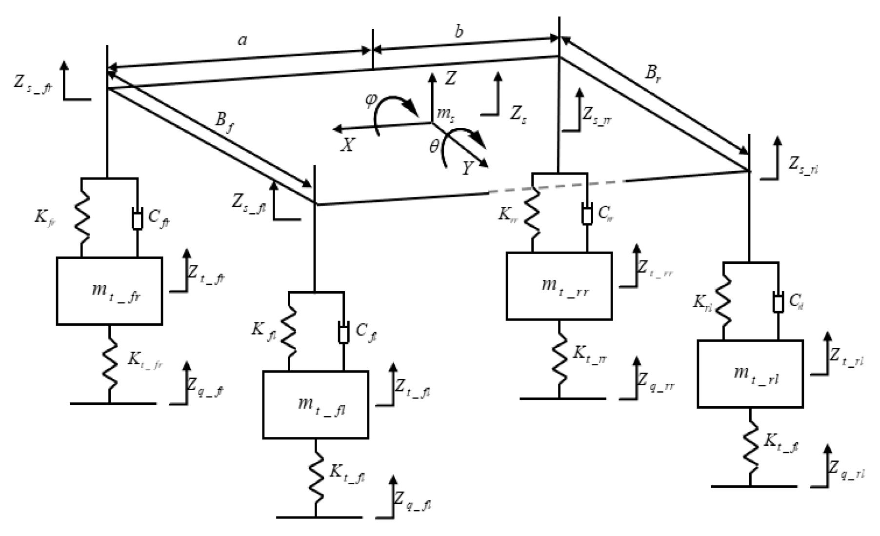
Figure 2.
Improved SH-ADD control suspension model.
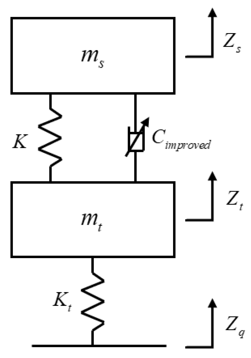
Figure 3.
Time—Domain Curve of Suspension System Output Response under Random Road Excitation.
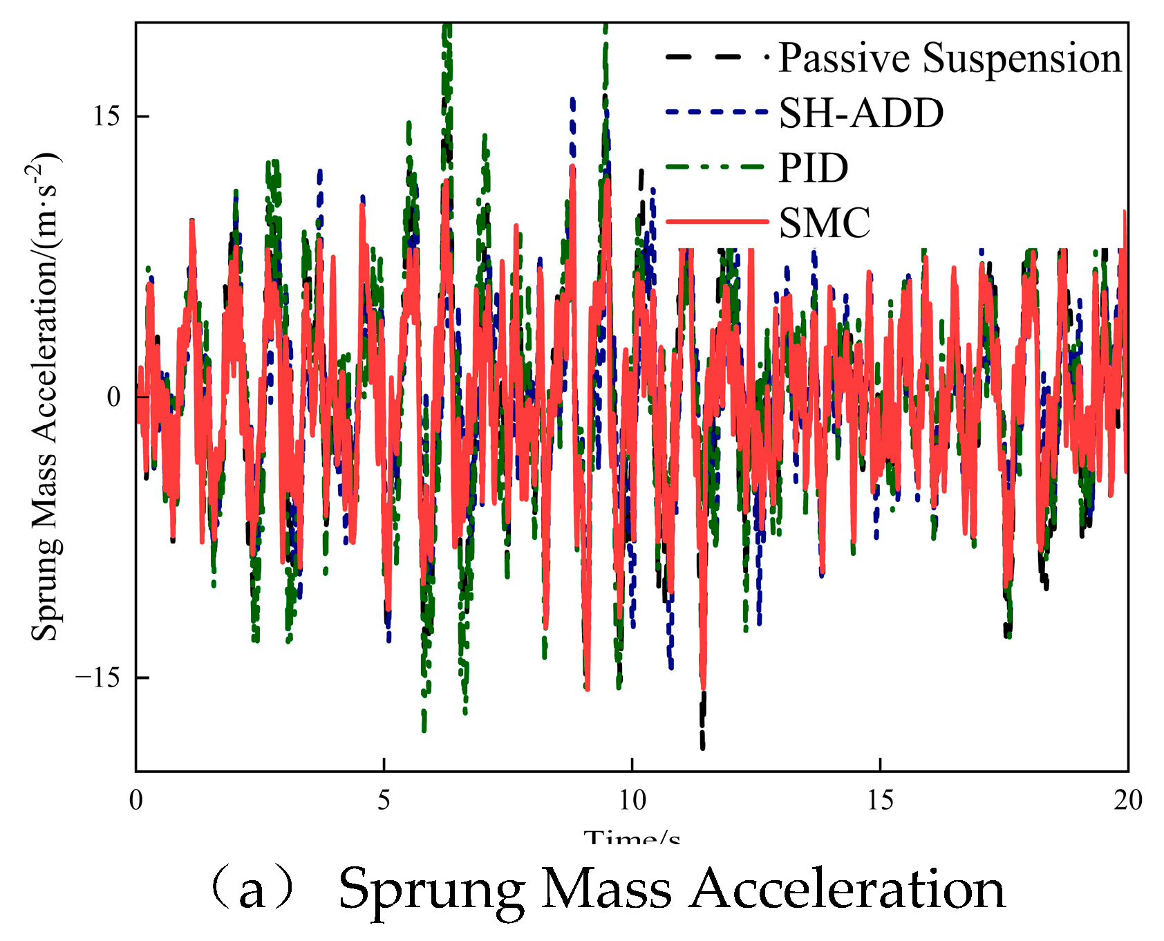
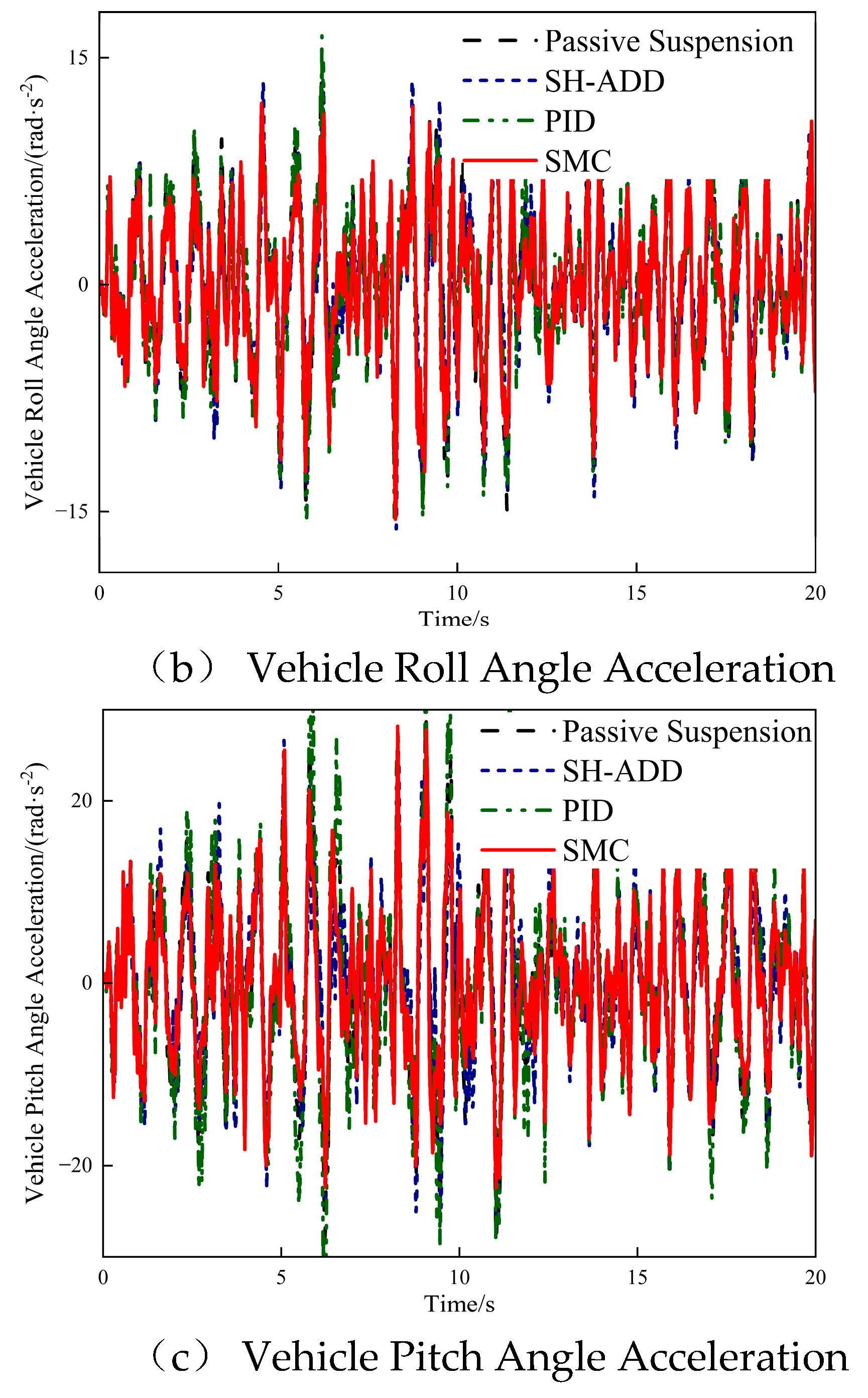
Figure 4.
Time—Domain Curve of Suspension System Output Response on Potholed Road.
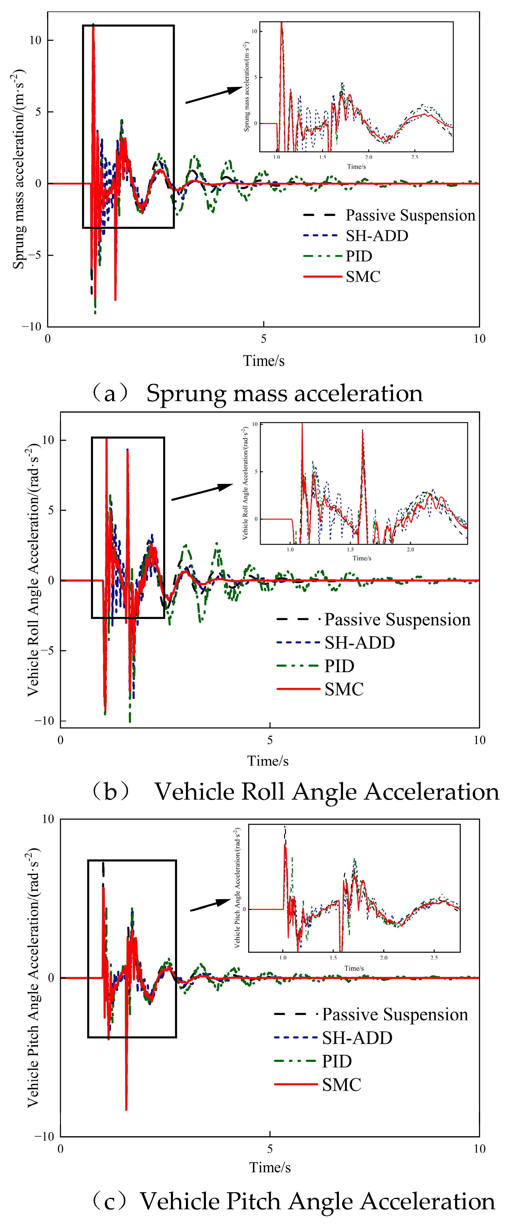
Figure 5.
Time—Domain Curve of Suspension System Output Response on Bump Road.
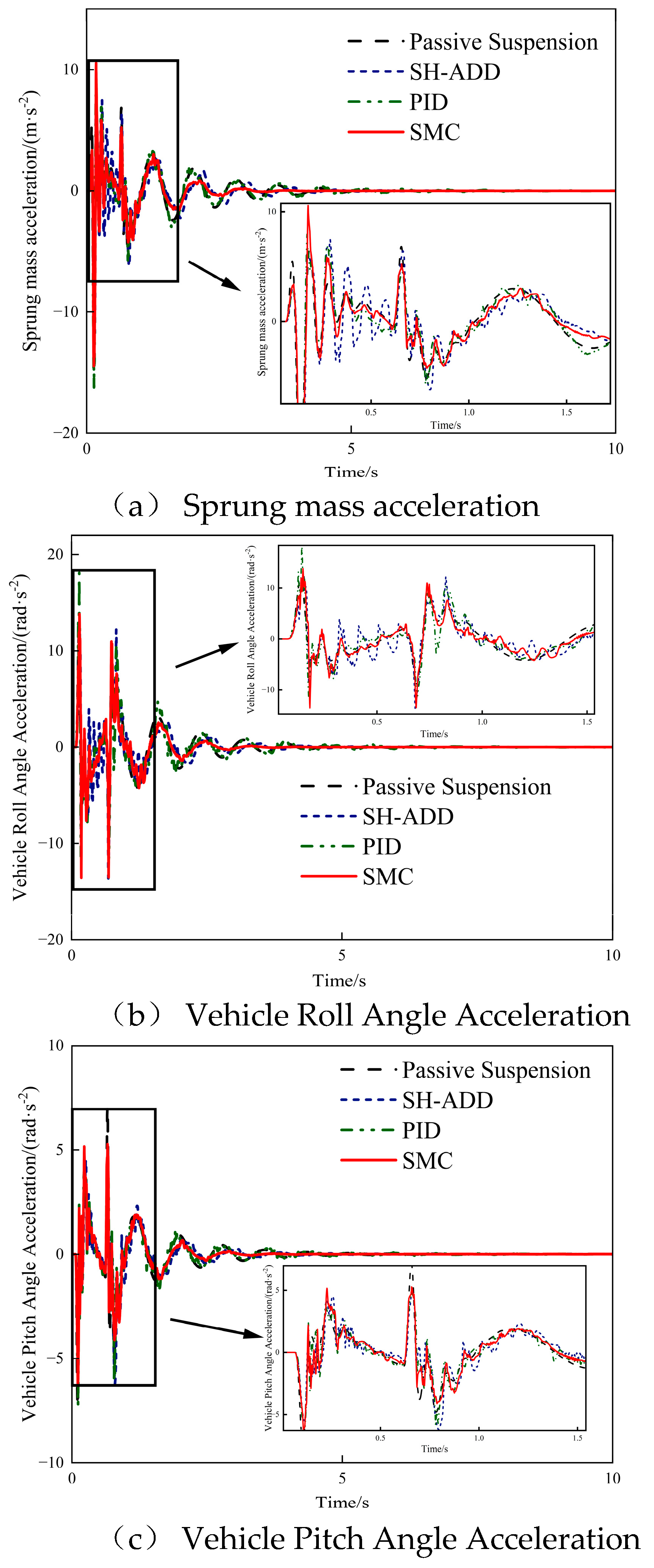
Figure 6.
RMS Plot of Suspension Response at Different Vehicle Speeds.
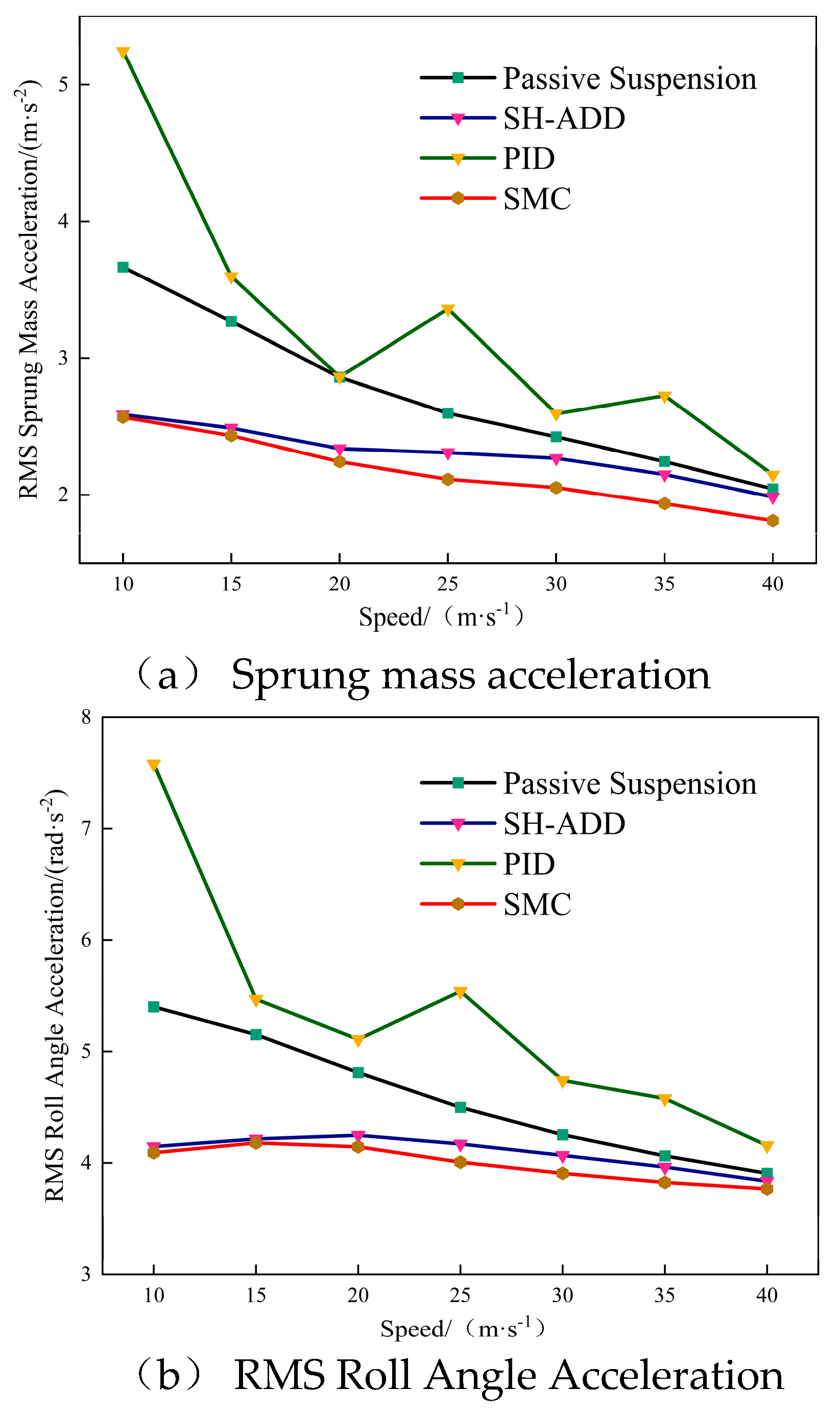
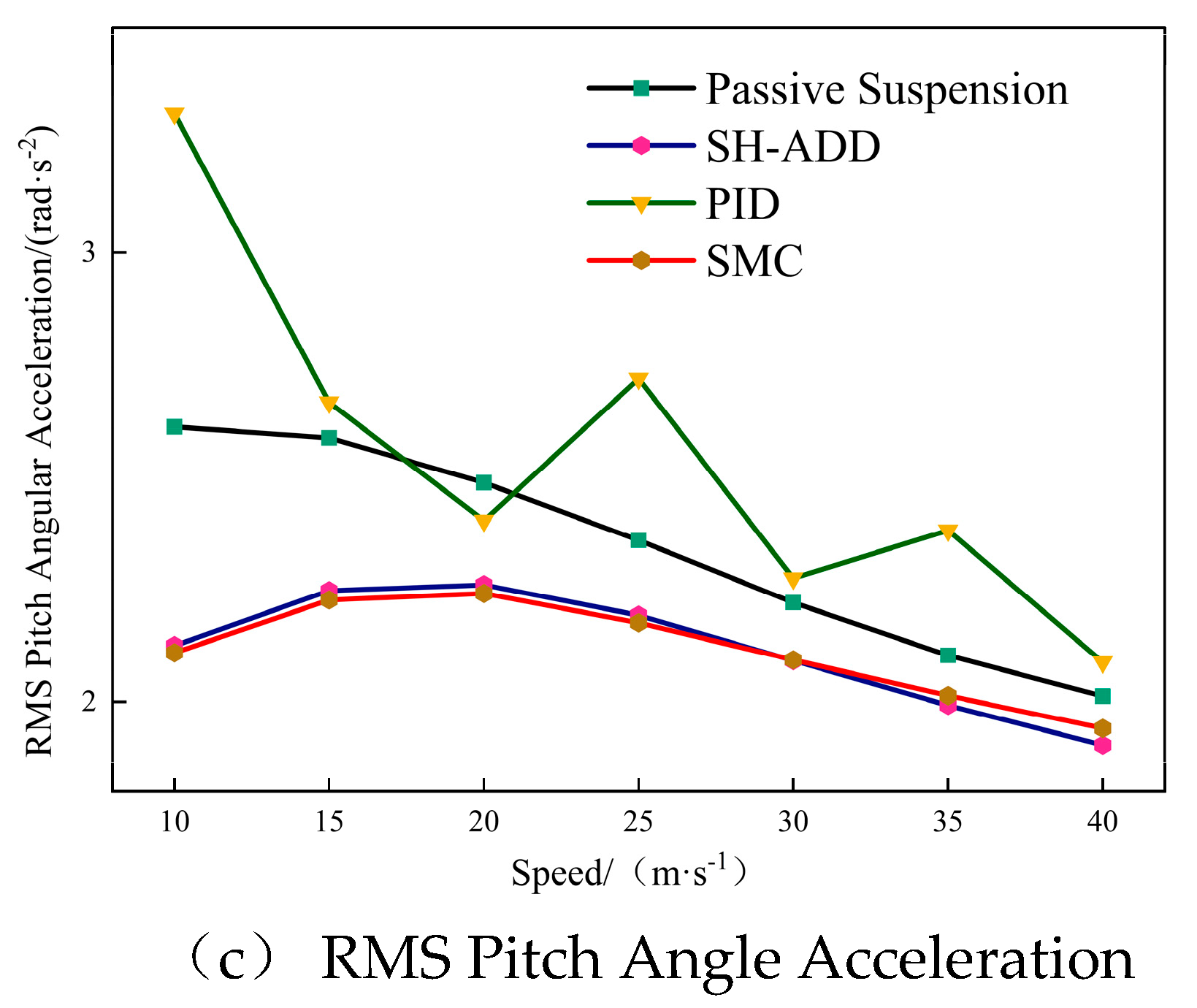
Figure 7.
RMS Plot of Suspension Response for Different Sprung Masses.
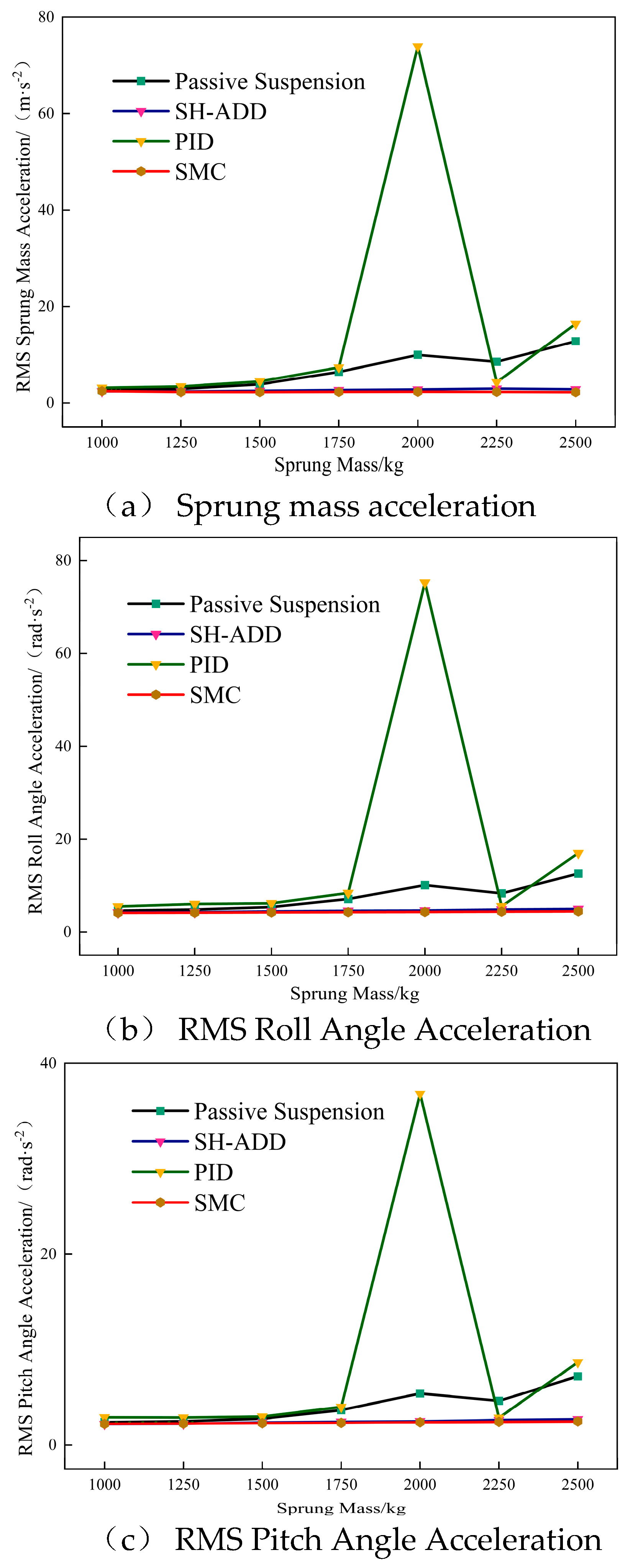

Table 1.
Whole vehicle suspension model parameters.
| Parameter name/ Units | Numerical | Parameter name/ Units | Numerical |
|---|---|---|---|
| 1235 | 192000 | ||
| 49 | 192000 | ||
| 49 | 1.25 | ||
| 49 | 1.51 | ||
| 49 | 1.415 | ||
| 30000 | 1.415 | ||
| 30000 | 1731 | ||
| 30000 | 472 | ||
| 30000 | 1500 | ||
| 192000 | 500 | ||
| 192000 | 3000 |
Table 2.
Comparison of RMS values for Class D road excitation.
| Control method | RMS | Percentage Improvement | ||||
|---|---|---|---|---|---|---|
| Passive Suspension | 5.72 | 4.98 | 9.62 | — | — | — |
| SH-ADD | 4.67 | 4.52 | 8.50 | -18.26% | -9.14% | -11.67% |
| PID | 5.68 | 4.80 | 10.11 | -0.64% | -3.61% | 5.06% |
| SMC | 4.48 | 4.48 | 8.29 | -21.64% | -9.90% | -13.87% |
Table 3.
Comparison of RMS Values on Potholed Road Surface.
| Control method | RMS | Percentage Improvement | ||||
|---|---|---|---|---|---|---|
| Passive Suspension | 0.68 | 0.75 | 0.44 | — | — | — |
| SH-ADD | 0.69 | 0.78 | 0.38 | 0.76% | 4.51% | -11.81% |
| PID | 0.74 | 0.87 | 0.45 | 8.89% | 16.03% | 2.66% |
| SMC | 0.64 | 0.67 | 0.41 | -6.68% | -10.40% | -5.38% |
Table 4.
Comparison of Steady-State Time on Potholed Road Surface.
| Control method | Settling Time/ | Percentage Improvement | ||||
|---|---|---|---|---|---|---|
| Passive Suspension | 4.27 | 4.24 | 3.84 | — | — | — |
| SH-ADD | 3.24 | 3.63 | 3.61 | -24.26% | -14.37% | -5.89% |
| PID | 4.37 | 2.69 | 3.93 | 2.25% | -36.73% | -29.99% |
| SMC | 3.15 | 3.14 | 3.11 | -26.15% | -26.04% | -18.96% |
Table 5.
Comparison of RMS Values on Bump Road Surface.
| Control method | RMS | Percentage Improvement | ||||
|---|---|---|---|---|---|---|
| Passive Suspension | 0.88 | 1.06 | 0.56 | — | — | |
| SH-ADD | 0.89 | 1.10 | 0.53 | 0.53% | 3.41% | -6.36% |
| PID | 1.21 | 1.44 | 0.68 | 36.68% | 35.88% | 20.84% |
| SMC | 0.84 | 1.01 | 0.51 | -5.07% | -4.38% | -9.17% |
Table 6.
Comparison of Steady—State Time on Bump Road Surface.
| Control method | Settling Time/ | Percentage Improvement | ||||
|---|---|---|---|---|---|---|
| Passive Suspension | 3.36 | 3.33 | 2.92 | — | — | — |
| SH-ADD | 2.32 | 2.71 | 2.69 | -31.07% | -18.51% | -7.87% |
| PID | 4.47 | 4.40 | 4.02 | 33.10% | 32.09% | 37.41% |
| SMC | 2.65 | 2.24 | 2.21 | -21.25% | -32.81% | -24.28% |
Disclaimer/Publisher’s Note: The statements, opinions and data contained in all publications are solely those of the individual author(s) and contributor(s) and not of MDPI and/or the editor(s). MDPI and/or the editor(s) disclaim responsibility for any injury to people or property resulting from any ideas, methods, instructions or products referred to in the content. |
© 2026 by the authors. Licensee MDPI, Basel, Switzerland. This article is an open access article distributed under the terms and conditions of the Creative Commons Attribution (CC BY) license (http://creativecommons.org/licenses/by/4.0/).
Copyright: This open access article is published under a Creative Commons CC BY 4.0 license, which permit the free download, distribution, and reuse, provided that the author and preprint are cited in any reuse.