
Submitted:
07 August 2026
Posted:
07 August 2026
You are already at the latest version
Abstract
Near-seabed contact operations with underwater hexapod robots can require one leg to execute a contact task, which reduces the stability of the remaining asymmetric five-legged support. To address this problem, this study proposes a five-legged asymmetric coordinated stability control method that integrates gait rhythm planning with attitude feedback. The method decouples the left middle leg from support, propulsion and CPG phase evolution to form a “5+1” asymmetric support base. This configuration reduces the periodic influence of task-induced disturbances on body balance. Meanwhile, a five-legged Hopf-CPG rhythm maintains continuous gait under asymmetric support. Low-bandwidth attitude feedback modulation is introduced between the CPG-generated foot trajectory and the inverse-kinematics input to balance attitude correction with foot-contact continuity. Full-degree-of-freedom underwater simulations in Webots show that, at a flow speed of 0.8 m/s, the method reduces combined attitude RMS by 41.52% relative to the no-feedback strategy. Relative to high-gain PD control, it reduces the RMS rate of change of the control output by 71.32%. These results indicate that the method improves input smoothness and compatibility with five-legged gait rhythms, with a moderate trade-off in transient attitude suppression. It therefore offers a coordinated approach to balancing attitude stability and gait continuity under asymmetric operation.
Keywords:
underwater hexapod robot
; asymmetric support
; Hopf-CPG
; low-bandwidth attitude feedback
1. Introduction
With the increasing complexity of marine resource development, underwater infrastructure maintenance and marine ecological monitoring, near-seabed detection and fine contact operations have become important demands in ocean engineering [1,2,3]. At present, near-seabed tasks such as underwater equipment maintenance, submarine optical cable inspection and coral-reef ecological observation still rely mainly on free-swimming platforms, especially remotely operated vehicles (ROVs) [4,5,6]. These platforms usually use multi-thruster vector arrangements to achieve hovering, station keeping and cruising, and they have mature technical advantages in open water and medium-to-long-range inspection [7]. However, when operations extend to complex environments close to the seabed, suspended propulsion exposes clear limitations [8,9,10,11]. Thruster jets can resuspend seabed sediments, increase water turbidity and obscure the field of view of optical sensors. For disturbance-sensitive targets, such as coral reefs and exposed or semi-buried optical cables, propeller wakes and sustained thrust during dynamic positioning may also cause additional environmental disturbance. In addition, manipulator operation in a suspended posture is easily coupled with current disturbance and contact reaction forces, making end-effector positioning accuracy and contact stability difficult to maintain over long periods.
By contrast, benthic legged platforms can form support polygons through discrete foot-seabed contacts and provide static or quasi-static support during near-seabed station keeping. This reduces reliance on continuous thruster hovering and improves station-keeping stability in complex near-seabed environments [12,13,14,15,16]. Existing studies have examined the near-seabed operational potential of underwater legged platforms from the perspectives of environmental disturbance suppression, station keeping, payload manipulation and locomotion under incomplete support. Liu et al. analysed the effects of thruster wakes, near-wall effects and sediment disturbance on close-range observation quality from a near-seabed observation perspective, highlighting the need for low disturbance near-seabed platforms [17]. Picardi et al. further showed through SILVER/SILVER2 that multi-legged contact locomotion can reduce disturbance to the seabed environment while supporting near-seabed exploration and underwater object grasping and placement [18]. Chellapurath et al. evaluated the station-keeping performance of underwater legged robots, providing a basis for stability assessment during near-seabed resident operations [19]. Zhang et al. designed an NCUUV robot that combines hexapod walking with fish-like morphology and uses CPG-based attitude control, verifying its potential for fixed-point underwater operations with a loaded manipulator [20]. Jun et al. analysed the dynamic tumble stability of a bio-inspired hexapod robot on a flat seabed under hydrodynamic forces, revealing the effects of frontal and lateral currents on steady-state stability [21].
On this basis, studies on locomotion control under single-leg failure or incomplete support in hexapod robots provide further references for five-legged asymmetric support. Lin et al. proposed a CPG-based fault-tolerant control method for a hexapod robot with single-leg failure, in which an improved Hopf oscillator and an asymmetric fault-tolerant tripod gait were used to generate fault-tolerant foot trajectories [22]. Other studies on single-leg fault-tolerant motion planning for hexapod robots also demonstrate the feasibility of maintaining locomotion continuity through support reconstruction and gait adjustment under a missing-leg condition [23,24]. However, most existing studies focus on platform configuration, near-seabed observation, station keeping, contact detection or post-failure fault-tolerant walking. Their main objective is usually to restore or maintain the overall locomotion capability of the robot. In near-seabed contact operations where one leg is intentionally released to perform sensing, contact or manipulation tasks, the remaining five legs do more than passively support a missing-leg body. They must maintain both attitude stability and foot-contact continuity under asymmetric support, periodic gait propulsion and task-induced disturbance coupling. Therefore, five-legged asymmetric coordinated stability control for single-leg task execution still lacks targeted investigation.
To address this problem, this study proposes a five-legged asymmetric coordinated stability control method that integrates gait rhythm planning with attitude feedback. The method decouples the left middle leg (LM) from support, propulsion and CPG phase coupling, allowing it to serve as a non-supporting functional leg for sensing, contact or manipulation tasks. Meanwhile, the remaining five legs form a “5+1” asymmetric support base and a five-legged Hopf-CPG rhythm to maintain phase-continuous basic foot motion. A low-bandwidth attitude feedback modulation interface is then introduced between the CPG-generated foot trajectory and the inverse-kinematics input. This interface generates body attitude offsets according to body roll, pitch and the corresponding angular velocities. It also suppresses high-frequency attitude correction through amplitude saturation, low-pass filtering and rate limiting, thereby reducing interference with gait rhythm and foot-contact continuity. The method addresses the coordinated demand for attitude stability and gait continuity in near-seabed asymmetric contact operations, providing a verifiable technical route for five-legged asymmetric support control during single-leg task execution.
2. System Modeling and Problem Definition
2.1. Physical Platform Structure and Simulation Model
This study uses an actual underwater bio-inspired hexapod robot platform as the research object, and the simulation experiments are conducted based on the physical platform. The platform adopts a hexapod discrete-support structure, in which each leg consists of hip, knee and ankle joints connected in series, enabling low-disturbance stable support through foot contact in near-seabed environments. To verify the control method under repeatable water flow disturbances, a Webots simulation model was built from the physical platform in SOLIDWORKS, using its geometric dimensions, joint configuration and motion range, as shown in Figure 1.
To describe the robot configuration, kinematic model and subsequent reconstruction of the five-legged working chain, the body coordinate system and leg kinematic model are first established. Following the coordinate convention adopted in the Webots model, the +z-axis points in the forward direction of the robot, the +x-axis points toward the left side of the robot body, and the +y-axis points upward. The body attitude is described by roll, pitch and yaw angles. Among them, roll and pitch directly reflect lateral and longitudinal attitude stability under water-flow disturbance.
The six legs of the robot are numbered according to the left-right and front-back positions of the body:
where, RF, RM and RR denote the right front, right middle and right rear legs, respectively, while LF, LM and LR denote the left front, left middle and left rear legs. The main structural parameters of the robot are listed in Table 1. The lengths of the coxa, femur and tibia links directly determine the foot reachable workspace and the geometric boundary of the five-legged support polygon. The joint motion ranges further constrain the feasible domain of subsequent inverse-kinematics inputs.
Each leg adopts a three joint serial structure consisting of hip, knee and ankle joints, as shown in Figure 2, and the zero position of each joint corresponds to the initial standing posture of the robot, with the joint variables defined as follows:
For any leg, the foot position relative to the corresponding leg coordinate system can be expressed by forward kinematics:
Correspondingly, given the desired foot position in the body coordinate system, the corresponding joint commands can be obtained through inverse kinematics:
2.2. Robot ‘5+1’ Asymmetric Configuration
Because the robot operates in a near-seabed underwater environment, the body structure must accommodate the centralized arrangement of the controller, power supply, communication module and sealed cabin. Mounting an independent external manipulator would increase the complexity of pressure sealing, cable routing, buoyancy trimming and structural integration. Therefore, the platform design preferentially uses the existing leg mechanism to undertake local sensing, attachment or contact tasks, reducing the effect of additional underwater actuators on structural complexity and sealing reliability.
In this study, the left middle leg (LM) is defined as a non-supporting operational leg that does not participate in support or propulsion. It is reserved for subsequent sensing, contact or manipulation tasks and is hereafter referred to as the task reserved leg. This design differs from conventional fault-tolerant studies of hexapod robots, where single-leg withdrawal is usually caused passively by damage or failure. In the present work, LM is actively released as a functional leg for potential sensor mounting, local contact or close-range operation. Therefore, during stable-base construction, LM does not participate in body support, propulsion or five-legged CPG phase coupling, and instead maintains a fixed safe reserved posture. The set of task reserved legs is defined as follows:
The remaining five legs form a five-legged work chain is
To clarify the functional boundary between LM and the five-legged working chain, the support participation indicator , propulsion participation indicator and CPG participation indicator are defined. For the task reserved leg LM:
As a result, the robot support and propulsion structure is transformed from a conventional symmetric hexapod configuration into a five-legged asymmetric configuration, as shown in Figure 3.
Set the current effective support leg set as , and the corresponding support polygon is
where, represents the convex hull formed by the effective support foot projection. After LM exits the support set, the support domain changes from an approximately symmetric hexapod support domain to a five-legged asymmetric support domain, altering both the support-polygon shape and the centre-of-mass projection margin. The stability margin can be described by the distance from the center of mass (COM) to the support boundary:
When the LM is changed from the support leg to the task reserved leg, the support set of the robot suddenly changes from to . The change does not simply reduce a driving unit, but directly changes the support convex hull formed by the foot contact points. Compared with the complete hexapod support domain, the five-legged support domain has boundary contraction and geometric center offset on the side of LM, which reduces the distance between the center of mass (COM) and the support boundary. Therefore, the center of mass (COM) constraint with a large margin in the hexapod symmetric configuration is transformed into a five-legged asymmetric constraint closer to the boundary after the task reserved leg is switched.
2.3. Five-Legged Asymmetric Stability Under Water Flow Disturbance
In order to verify the attitude stability of the five-legged support chain of the task reserved leg under the disturbance of water flow, the Fluid node is used to construct the directional flow environment in Webots. The Fluid node of Webots is used to describe the fluid region with properties such as density, viscosity and flow rate. When the rigid body of the robot enters the fluid area and the corresponding Immersion properties are set, the simulator can calculate the buoyancy, drag and drag moment according to the immersion state, reference area and relative speed.
In this study, the water flow drag is regarded as an external disturbance acting on the body attitude and foot contact process. The five-legged Hopf-CPG is responsible for providing the basic rhythm, and the subsequent attitude feedback modulation interface is responsible for compensating the low frequency attitude offset caused by the disturbance after the CPG output and before the inverse kinematics input. While it preserves the phase continuity of the CPG, it avoids the direct coupling of the complex hydrodynamic model into the rhythm generator. The water flow drag can be approximated as follows:
where, is the water density, is the equivalent drag coefficient, is the equivalent upstream projection area, and is the speed of the robot relative to the incoming flow. The equivalent quadratic drag model is used to describe the main disturbance effect of water flow on the robot body and foot rigid body. For a rigid body with characteristic length , the Reynolds number can be estimated as follows:
where, is the water density, is the dynamic viscosity, and is the inflow speed. In this study, the water flow speed is 0.5 ~ 0.8 m/s, and the local characteristic length of the robot leg and the body is about 0.05 ~ 0.19 m.When and , . Therefore, although the working condition is a low speed near bottom motion, the hydrodynamic force of the receiving rigid body is mainly in the inertial drag dominant interval, and the quadratic drag term can be used to approximately describe the main flow disturbance.
The simulations were designed to compare the relative performance of different control methods under identical disturbance conditions, rather than to provide a high-fidelity prediction of the hydrodynamic loads. Therefore, a unified equivalent drag coefficient of was adopted in Webots to construct a deterministic and repeatable directional-flow disturbance environment. Identical flow and dynamic parameters were used for all compared methods. This simplified model supports controlled comparative evaluation but does not replace experimental hydrodynamic calibration or permit quantitative extrapolation to real ocean-current conditions.
The specific parameters are shown in Table 2.
2.4. Evaluation Metrics
According to the five-legged support-domain change and the water flow disturbance torque model, stable-base control under the task reserved leg condition must satisfy three constraints: attitude stability, support-geometry feasibility and control-input continuity. First, water flow drag acting on the body and leg rigid bodies generates an equivalent attitude disturbance torque, making roll and pitch the main state variables for evaluating base stability. Second, after LM is decoupled from the support set, the margin from the centre-of-mass projection to the support boundary decreases. Therefore, the number of effective support feet and foot-contact continuity directly determine whether the five-legged base remains feasible. Finally, the attitude feedback used in this study does not directly change the internal state of the CPG oscillator. Instead, it enters the inverse-kinematics layer as a body attitude offset. If the offset changes too rapidly, it may cause abrupt foot or joint commands and disrupt the continuity of the five-legged rhythm, even when attitude RMS is reduced.
Therefore, the control objective of this study is to reduce roll/pitch attitude fluctuations through constrained body correction without changing the internal state of the basic five-legged Hopf-CPG rhythm. The objective also includes suppressing the influence of the correction rate on inverse-kinematics input and foot-contact continuity.
For attitude stability, the root mean square (RMS) values of roll and pitch are used as the main evaluation metrics. These metrics characterize the overall attitude fluctuations in the roll and pitch directions, respectively, and are calculated as follows:
where, and represent the roll and pitch at the sampling time, , respectively, and is the number of samples in the statistical window. Since RMS can reflect the average attitude fluctuation in the whole statistical window, it is not sensitive to the instantaneous extreme response. Therefore, the attitude peak is further used as an auxiliary index to describe the maximum attitude offset that may occur under the change of water flow disturbance or support state. The calculation form is
In terms of the control output continuity, the body attitude correction and its correction rate that eventually enter the inverse kinematics reference layer are the focus in the paper. The correction amplitude evaluates the adjustment intensity of the low-bandwidth attitude feedback applied to the body reference posture, and it can be characterized by the body reference correction . Compared with simply reducing the attitude error, this study emphasizes the temporal continuity of the correction. Therefore, the correction rate of the correction is further used to evaluate the smoothness of the control output. The root mean square form is
where, represents the reference correction of the body, represents the limited correction of the actual input inverse kinematics layer at the sampling time after low-pass filtering, amplitude limitation and correction rate constraint, and is the sampling interval.
To assess whether attitude modulation disrupted the nominal five-legged support pattern, we additionally evaluated the number of supporting legs, the static centre-of-mass (COM) support margin, the support-polygon area and the insufficient-support ratio. At each valid time step, the nominal support polygon was reconstructed from the foot positions of the five working legs marked as being in the support phase. The signed static COM margin was defined as the distance between the projected COM and the boundary of the support polygon, with negative values indicating that the projected COM lay outside the polygon. The insufficient-support ratio was defined as the proportion of valid samples with fewer than three supporting legs. Contact continuity was further characterized using the contact-anomaly ratio derived from discrepancies between the commanded support state and the raw foot-touch state.
The number of effective support feet describes how many support feet in the five-legged working chain maintain effective contact at sampling time , and is defined as follows:
The contact-anomaly ratio is used to calculate the degree of support loss or contact anomalies in the entire evaluation window, which is defined as follows:
where, is the contact state of the working leg at the sampling time. When , it means that the contact is effective, and when , it means that the contact is abnormal or the support is missing, and is the indicator function.
3. CPG-Attitude Coordinated Stability Control Method
3.1. Control Framework
The control architecture adopts a serial framework consisting of basic rhythm generation, attitude feedback modulation and inverse-kinematics execution. The five-legged Hopf-CPG layer generates phase-continuous basic foot trajectories. The attitude feedback modulation interface generates body attitude offsets from body roll, pitch and their angular velocities, and suppresses high frequency corrections through amplitude saturation, low-pass filtering and rate limiting. The resulting offset is introduced as low-bandwidth modulation between the CPG output and the inverse-kinematics input. This improves body attitude stability while preserving CPG rhythm continuity. The framework is shown in Figure 4.
3.2. Five-Legged Hopf-CPG Rhythm for the Asymmetric Configuration
In this study, Hopf-CPG is used as the basic rhythm generation layer of low-speed five-legged locomotion. The layer is responsible for providing a continuous, adjustable and phase-clear basic foot trajectory. The working leg corresponds to a Hopf oscillator, whose amplitude and phase are and , respectively. For , the oscillator can be written as :
where, is the amplitude convergence coefficient, is the target amplitude parameter, is the fundamental angular frequency, is the phase coupling adjacency set, is the coupling strength, and is the desired phase difference. After the LM enters the task reservation state, it is separated from the working CPG network, no longer participates in phase coupling and foot trajectory generation, and the controller does not reset the instantaneous phase of the remaining five oscillators, but maintains the phase continuity of the five-legged network.
The basic foot trajectory of the working leg is superimposed by the neutral foot position in the 5+1 configuration and the CPG periodic displacement.
where, is the neutral foot position after 5+1 configuration reconstruction, and is the periodic foot displacement obtained by CPG output mapping.
In this study, the five-legged phase sequence of LF-RM-LR-RF-RR is used to maintain the continuous wave rhythm under asymmetric configuration. The phase of the five-legged rhythm is shown in Figure 5.
3.3. Rhythm-Compatible Attitude Feedback Modulation Interface
Under conventional symmetric hexapod support, each control period generates attitude correction directly from current roll/pitch attitude errors and angular velocities. The correction is sent directly to the inverse-kinematics layer. Such fast attitude feedback helps suppress instantaneous attitude errors. Its typical form can be expressed as
In the five-legged asymmetric CPG gait, the body attitude error is not completely caused by the water flow disturbance. It also includes the gait synchronization component caused by the support phase switching, swing leg lifting and foot-contact transitions. The attitude error can be simplified as
where, is the attitude observation, is the low-frequency attitude offset caused by water flow drag and asymmetric support. is the periodic attitude component related to the CPG rhythm,and is sensor or numerical noise.The and are estimated by the body IMU attitude. The and can be used to estimate the IMU angular velocity.
It is difficult to distinguish and by directly inputting high-bandwidth attitude feedback into the inverse kinematics layer. It is easy to quickly compensate the attitude micro-oscillation in the gait cycle as a control error, so that the inverse kinematics input produces a large correction rate. Therefore, direct high-bandwidth attitude control is not used in the paper, but it constrains the attitude feedback to a low-bandwidth, limited amplitude and continuous rate of change modulation.
The above analysis indicates that an attitude feedback interface suitable for five-legged CPG should not track all frequency components of the attitude error. It should mainly act on the low-frequency attitude deviation caused by water flow drag and asymmetric support. To ensure compatibility between attitude feedback and CPG rhythm, the attitude offset finally input to the inverse-kinematics layer must satisfy three constraints:
where, is the body correction after filtering, is the allowable maximum body correction, is the allowable maximum correction correction rate, is the body correction after the correction rate limit, is the control period, is the equivalent cut-off angular frequency of the attitude feedback modulation interface, and is the CPG basic angular frequency.
When the low bandwidth parameter is too small, the attitude correction response is slow, and it is difficult to suppress the attitude offset after disturbance in time. When the low-bandwidth parameter is close to or exceeds 1, the attitude correction may follow the attitude oscillation during the gait cycle, resulting in the inverse kinematics input jitter and weakening the CPG rhythm continuity. Therefore, this study takes the low bandwidth parameter as a compromise parameter between attitude suppression ability and control output smoothness, and analyzes its influence through subsequent parameter ablation experiments.
The attitude feedback modulation interface is constructed under the condition of satisfying the constraint. First, the raw body correction is calculated from roll, pitch and their angular velocities:
where, is the attitude offset without bandwidth and amplitude constraints, and are the proportional and derivative gain matrices, respectively. In order to facilitate the adjustment of roll channels and pitch channels respectively, the form of sub-channel gain is
The raw correction is then processed in three steps.
- 1)
- Amplitude saturation
- 2)
- The first-order discrete low-pass filter is used to generate low-pass attitude offset.
The corresponding frequency domain amplitude is
When , the attenuation of the attitude feedback component near the CPG dominant frequency by the low-pass filter is
A suitable time constant tau can attenuate the high frequency component in attitude feedback that is synchronized with the CPG main frequency. Thus, the final attitude correction mainly retains the low-frequency water flow disturbance component.
3) In order to further ensure the continuity of the body input, the correction rate limit is applied to the low-pass attitude offset.
where, means to truncate by the upper and lower boundaries.
After the above processing, the attitude feedback channel no longer directly tracks all frequency components in the attitude error. Instead, it forms an attitude feedback modulation interface with limited amplitude, limited bandwidth and continuous rate of change. Its mechanism is shown in Figure 6. The interface mainly retains compensation for the low-frequency attitude deviation caused by water flow disturbance and five-legged support asymmetry, while suppressing high frequency attitude-correction components synchronized with the CPG gait cycle. This reduces interference with five-legged rhythm continuity.
3.4. Mapping Attitude Offset to Inverse Kinematics Input
The attitude offset after bandwidth, amplitude and rate constraints does not change the internal state of the CPG oscillator. Instead, it enters the inverse-kinematics input layer as a body attitude correction. Assuming that the nominal body attitude without adjustment is , the adjusted body attitude is
For the working leg, the final joint command is determined by the basic CPG foot trajectory and the adjusted body attitude.
where, represents the inverse kinematics mapping of the leg. The expression shows that the attitude feedback in this study does not directly generate an independent foot compensation trajectory. Instead, it introduces a continuously varying body attitude offset in the inverse kinematics layer. Therefore, the basic foot rhythm is still determined by Hopf-CPG.The attitude feedback modulation interface only changes the low-frequency component of the body attitude.
The LM is not involved in the trajectory synthesis of the five-legged work chain, and its foot target is given separately by the task module or the preset safe pose.
Overall, water flow disturbance acts on the asymmetric five-legged base and induces low-frequency attitude deviations. The Hopf-CPG provides a phase-continuous five-legged basic rhythm. The attitude feedback modulation interface maps roll/pitch and angular velocity feedback into a constrained attitude offset. The inverse-kinematics layer maps the basic CPG foot trajectory and this attitude offset jointly into joint commands. With this design, attitude feedback mainly acts on the low-frequency component of body attitude without modifying the CPG oscillator states or the prescribed inter-leg phase relationships. The method thereby achieves rhythm compatible attitude regulation of the five-legged stable base under the task reserved leg condition.
4. Simulation Verification and Results
4.1. Simulation Setting and Experimental Design
A Webots-based simulation environment for water flow disturbance experiments was established to verify the proposed stable-base construction method. The method integrates five-legged CPG and attitude feedback for an underwater hexapod robot with a task reserved leg, as shown in Figure 7. The six legs are denoted as RF, RM, RR, LF, LM and LR, with LM set as the task reserved leg. After the robot enters the five-legged task condition, LM no longer participates in support phase determination, contact feedback, propulsion-trajectory generation or attitude-correction allocation. Its foot target is specified by an independent safe posture or task reserved posture. The remaining legs, RF, RM, RR, LF and LR, form the five-legged working chain for low speed rhythmic locomotion and body attitude stabilization.
The experiments were conducted under directional water flow disturbance, with the incoming flow acting along the longitudinal direction of the robot. The water flow speed is set to 0 m/s, 0.5 m/s and 0.8 m/s, respectively, corresponding to static water, medium water flow and strong water flow conditions. Each flow-speed and control-method condition contained five simulation runs. Metrics were calculated over the 20–120 s evaluation window, containing 2,500 time samples per run. Each simulation run, rather than each time sample, was treated as one evaluation unit. Trial-level values and descriptive summaries are reported. Because several runs performed under fixed simulation settings produced identical or nearly identical metrics, the repeated samples were used to assess numerical repeatability and were not treated as independent observations for inferential significance testing. The detailed parameters are shown in Table 3.
Three comparison methods were considered:
B1: five-legged basic CPG method. LM is decoupled from the support and propulsion chains as the task reserved leg. The remaining five legs use the Hopf-CPG to generate the basic rhythm, without attitude feedback regulation. This method characterizes the natural attitude degradation of the basic five-legged working chain under water-flow disturbance in the task reserved leg condition.
B2: five-legged CPG with conventional attitude PD control. Conventional attitude PD feedback is introduced on top of the five-legged CPG, and body attitude correction is generated directly from roll/pitch attitude errors and angular velocities. This method provides a fast attitude feedback baseline and reflects the attitude suppression capability of high-bandwidth control.
Ours: five-legged CPG with low-bandwidth attitude modulation. An attitude feedback modulation interface is introduced between the CPG foot trajectory output and the inverse-kinematics input. Through amplitude constraints, low-pass filtering and rate limiting, roll/pitch attitude feedback is converted into a low-bandwidth and continuously varying body offset. This method tests whether attitude fluctuations can be reduced while substantially decreasing the correction rate entering the inverse-kinematics layer.
In addition to the main comparison experiments for B1, B2 and Ours, a low-bandwidth parameter ablation experiment was conducted under the 0.8 m/s condition. This experiment analyzes how the low-pass time constant affects attitude suppression, control-output smoothness and contact continuity. The experimental action sequence of the hexapod robot is shown in Figure 8.
The three methods use the same robot model, task reserved leg setting, basic five-legged CPG parameters and water flow disturbance conditions. They differ only in the attitude feedback regulation module. The experiments were evaluated using three categories of metrics. The first category describes attitude stability, including roll RMS, pitch RMS, combined attitude RMS and peak attitude deviation. The second category describes control output smoothness, including the RMS of the body correction rate and the total variation of the body correction. The third category contains auxiliary contact and support metrics, including the contact-anomaly ratio.
4.2. Experimental Results
For B1, which has no attitude feedback, the roll/pitch responses under different flow speeds were plotted to obtain Figure 9. These curves illustrate the stability degradation of the five-legged working chain under strong water flow disturbance after LM is reserved for task use. Under still water and moderate flow (0.5 m/s), the combined attitude RMS values of B1 were 0.2286° and 0.2551°, respectively, both remaining at low levels. When the flow velocity increased to 0.8 m/s, the combined attitude RMS of B1 increased to 1.0268°, approximately 4.49 times the still-water value. These results indicate that strong flow substantially amplifies attitude fluctuations in the five-legged support chain with a task reserved leg, and that the basic five-legged CPG alone cannot fully accommodate disturbances near the stability boundary.
From the results of the sub-channels, the growth rate of the pitch RMS of B1 is substantially greater than that of the roll channel, indicating that after LM withdraws from the support and propulsion chain, the five-legged asymmetric support configuration is more likely to induce low-frequency fluctuations in the pitch direction under the action of strong water flow. Barely relying on the basic five-legged CPG rhythm can maintain the basic motion under low disturbance conditions, but it is still necessary to introduce attitude feedback regulation under strong water flow conditions.
According to the data in Table 4, the attitude RMS and peak values of B1, B2 and Ours under three water flow conditions are further compared. Compared with B1, Ours reduces the combined attitude RMS at all flow rates, indicating that the low-bandwidth limited attitude feedback can effectively alleviate the attitude fluctuation under the five-legged condition of the task reserve leg. In terms of attitude RMS alone, Ours performs slightly worse than B2, indicating that conventional PD has stronger instantaneous attitude suppression ability without considering output smoothness and rhythm compatibility.
Figure 10 compares the roll and pitch responses of B1, B2 and Ours at 0.8 m/s. The reduction in combined attitude RMS achieved by Ours relative to B1 is greatest under the strong-flow condition, indicating improved suppression of flow-induced low-frequency pitch oscillations. Compared with B2, Ours yields slightly higher combined attitude RMS values at all three flow speeds, while the differences remain small. This trade-off reflects the different control objectives. B2 prioritizes rapid attitude-error suppression, whereas Ours constrains the attitude-feedback signal to form a low-bandwidth, amplitude-limited and continuously varying modulation input, thereby reducing high-frequency perturbations to the periodic foot trajectories generated by the five-legged CPG.
Attitude RMS reflects only the magnitude of body attitude error. It does not indicate whether the control input produces abrupt changes in foot trajectories. Therefore, attitude feedback constraints are necessary. To assess whether attitude feedback can provide the required attitude suppression without disrupting five-legged rhythm continuity, the body correction rate and total correction variation of B2 and Ours were further compared.
As shown in Table 5, compared with B2, Ours reduced the correction rate RMS from 0.02393, 0.02506 and 0.06006 to 0.00676, 0.00751 and 0.01722 at 0, 0.5 and 0.8 m/s, respectively. The corresponding reductions were 71.75%, 70.04% and 71.32%. These data show that low-bandwidth attitude modulation substantially reduces high-frequency variations entering the inverse-kinematics input layer.
Figure 11 plots the body correction and its rate for B2 and Ours. Compared with B2, Ours has a slightly higher attitude RMS, confirming the advantage of fast PD control in instantaneous attitude suppression. However, Ours reduces the control-output rate by approximately 70% at a small attitude cost, thereby decreasing high frequency variations entering the inverse-kinematics input layer. For the five-legged CPG condition with a task reserved leg, this better matches the requirements of a stable observation base than simply minimizing attitude RMS.
In legged robots, attitude feedback may also change the load and contact state of the foot. Therefore, in addition to the attitude and control output indicators, we additionally evaluated the number of supporting legs, the static center of mass (COM) support margin, the support-polygon area and the insufficient-support ratio.
Table 6 shows that, under 0 and 0.5 m/s conditions, the contact anomaly ratios of all three methods remain generally low. This indicates that the five-legged working chain can maintain basic contact continuity in still water and moderate flow. Under the 0.8 m/s strong flow condition, the contact anomaly ratios of all three methods increase markedly, indicating that this condition approaches the stability boundary of five-legged support. At this velocity, the contact anomaly ratio is 0.2769 for B2 and 0.2606 for Ours, representing a 5.90% reduction relative to B2. The number of contact anomaly events also decreases from 240.6 for B2 to 229.4 for Ours. These results indicate that low-bandwidth attitude modulation can partly alleviate contact state fluctuations caused by rapid corrections in conventional PD control.
Table 7 mean static COM margin obtained with Ours was 0.02943, which was 17.4% higher than that of B1 and 3.5% lower than that of B2. Similarly, the mean support-polygon area obtained with Ours was 3.95% larger than that of B1 and 1.37% smaller than that of B2. These results show that the low-bandwidth controller substantially smoothed the body-correction input while maintaining nominal support-geometry metrics close to those of B2.
5. Conclusions
Actively reserving one leg for a potential sensing or contact task converts a hexapod robot from a redundant six-legged support configuration into an asymmetric five-legged system, increasing its sensitivity to hydrodynamic disturbances. To address this problem, this study developed a coordinated stability-control method that integrates five-legged Hopf-CPG gait-rhythm planning with low-bandwidth attitude feedback. The attitude-feedback interface was placed between the CPG foot-trajectory output and the inverse-kinematics input. Amplitude limitation, low-pass filtering and rate limitation were used to convert roll and pitch feedback into continuous body-correction commands, while the left-middle leg remained decoupled from the support and propulsion chains as the task reserved leg.
Webots simulations conducted at flow speeds of 0, 0.5 and 0.8 m s−11 showed that the basic five-legged CPG became increasingly susceptible to attitude fluctuations as the flow speed increased. Compared with B1, the proposed method reduced the overall attitude fluctuation at all tested flow speeds, with the largest improvement observed at 0.8 m−1s−1. Although B2 achieved slightly lower attitude RMS values, the proposed method reduced the RMS of the control-output rate by approximately 70% and substantially decreased the total variation of the body-correction input. The nominal support-geometry metrics also remained close to those of B2 under the strong-flow condition. Taken together, these results show that the proposed method achieves a practical trade-off between attitude regulation and command smoothness, rather than simply minimizing attitude error.
The present validation was limited to a simplified Webots hydrodynamic model, one task reserved leg position, a fixed reserved-leg posture and a predominantly longitudinal flow direction. CPG phase error, foot slippage, contact force and task-induced interaction forces were not measured directly. Future work should therefore evaluate the method in calibrated water-tank experiments with actual task-leg interactions, reconstruct the support polygon from measured foot-contact states, and test different reserved-leg positions, flow directions, terrain conditions and task loads. These investigations will determine whether the stability–smoothness trade-off observed in simulation can be transferred to physical near-seabed robotic operations.
Author Contributions
Conceptualization, W.L. and L.C.; methodology, W.L.; software, W.L.; validation, W.L.; formal analysis, W.L.; investigation, W.L., Z.S. and J.Y.; resources, J.Y., H.Z. and L.C.; data curation, W.L.; writing-original draft preparation, W.L.; writing-review and editing, W.L. and L.C.; visualization, W.L.; supervision, L.C.; project administration, L.C.; robot structural design, Z.S. and J.Y.; low-level architecture design, Z.S. and J.Y.; physical prototype assembly, Z.S. and H.Z. All authors have read and agreed to the published version of the manuscript.
Funding
This research received no external funding.
Institutional Review Board Statement
Not applicable.
Informed Consent Statement
Not applicable.
Data Availability Statement
Data available upon request.
Conflicts of Interest
The authors declare no conflicts of interest.
Appendix A
Appendix A.1. Ablation Analysis of Low-Bandwidth Parameters
To show that the low-bandwidth parameters are not selected arbitrarily, a parameter ablation analysis was conducted after the main comparison experiments. The ablation experiment explains how the low-pass time constant and the correction rate limit affect the trade-off between attitude suppression and input smoothness. In all ablation groups, LM was fixed as the task reserved leg, the incoming flow velocity was fixed at 0.8 m/s, and the same robot model, CPG parameters and evaluation window were used.
The ablation study contains two categories. In the first category, the pitch and roll channel correction rate limits are fixed at 0.050 and 0.040, respectively, while only the low-pass time constant tau is varied. This category examines how low-pass strength affects response speed and smoothness. In the second category, tau is fixed at 0.15 s, and the correction rate limit is further reduced to determine whether excessive rate limiting causes attitude response lag.

Table A1.
Low-bandwidth parameter ablation results.
| Group | tau/s | Pitch speed limit | Roll speed limit | Combined attitude RMS(°) | Roll Correction rate |
Pitch Correction rate |
|---|---|---|---|---|---|---|
| TAU000 | 0.00 | 0.050 | 0.040 | 0.5755 | 0.01519 | 0.02979 |
| TAU010 | 0.10 | 0.050 | 0.040 | 0.5933 | 0.00970 | 0.02446 |
| TAU015 | 0.15 | 0.050 | 0.040 | 0.5998 | 0.00729 | 0.02104 |
| TAU030 | 0.30 | 0.050 | 0.040 | 0.6084 | 0.00412 | 0.01320 |
| TAU050 | 0.50 | 0.050 | 0.040 | 0.6104 | 0.00257 | 0.00861 |
| RATE0020 | 0.15 | 0.025 | 0.020 | 0.5999 | 0.00699 | 0.01781 |
| RATE0010 | 0.15 | 0.012 | 0.010 | 0.6165 | 0.00567 | 0.00984 |
Table A1 shows that, under 0.8 m/s water flow disturbance, the low-bandwidth parameters strongly affect both attitude stability and control output smoothness of the five-legged working chain. Without low-pass filtering, namely in the TAU000 condition, the unfiltered attitude feedback responds fastest. However, the control correction more readily follows gait cycle oscillations and instantaneous disturbance variations, which weakens the isolation of CPG rhythm by low-bandwidth regulation. As the low-pass time constant increases, the attitude correction rate decreases substantially. TAU015 achieves a favorable trade-off between attitude holding accuracy and control output smoothness. In contrast, when the time constant increases further to TAU030 and TAU050, the correction rate continues to decrease but the attitude response to water flow disturbance becomes weaker. This causes controller lag and leads to the accumulation of pitch direction attitude error.
The rate-limiting ablation results further support this conclusion. After tightening the rate limit based on TAU015, RATE0020 keeps the combined attitude RMS almost unchanged, but the pitch channel rate limit triggering ratio increases to 43.38%. When the limit is further tightened to RATE0010, the pitch correction rate RMS decreases to 0.00984, while the combined attitude RMS increases to 0.616°. The roll and pitch channel rate-limit triggering ratios also reach 24.29% and 62.62%, respectively. These results show that an excessively small correction rate limit keeps attitude correction in a rate-limited state for long periods. Although output smoothness is further improved, disturbance-compensation capability is weakened.
Based on these results, TAU015 was selected as the main parameter setting for low-bandwidth attitude regulation. This parameter combination maintains a low attitude RMS under strong water flow disturbance while substantially reducing the attitude correction rate. It also prevents attitude compensation from directly following CPG gait oscillations or instantaneous disturbance fluctuations. The ablation experiments show that low-bandwidth attitude modulation does not simply weaken attitude feedback. Instead, it provides an adjustable engineering trade-off among attitude stability, control smoothness and five-legged support continuity.
References
- Yang, C.; Liu, S.; Su, H.; Zhang, L.; Xia, Q.; Chen, Y. Review of underwater adsorptive-operating robots: Design and application. Ocean Eng. 2024, 294, 116794. [Google Scholar] [CrossRef]
- Nauert, F.; Kampmann, P. Inspection and maintenance of industrial infrastructure with autonomous underwater robots. Front. Robot. AI 2023, 10, 1240276. [Google Scholar] [CrossRef] [PubMed]
- Ho, M.; El-Borgi, S.; Patil, D.; Song, G. Inspection and monitoring systems subsea pipelines: A review paper. Struct. Health Monit. 2020, 19, 606–645. [Google Scholar] [CrossRef]
- Kanashiro, R.A.; Piai Paiva, J.C.; Nunes, W.R.B.M.; de Melo, L.F. Remotely Operated and Autonomous Underwater Vehicles in Offshore Wind Farms: A Review on Applications, Challenges, and Sustainability Perspectives. Sustainability 2026, 18, 2. [Google Scholar] [CrossRef]
- Sitler, J.; Sowrirajan, S.; Englot, B.; Wang, L. A Bimanual Teleoperation Framework for Light Duty Underwater Vehicle-Manipulator Systems. In Proceedings of the 2024 21st International Conference on Ubiquitous Robots (UR), New York, NY, USA, 24–27 June 2024; pp. 1–8. [Google Scholar]
- Liu, J.; Iacoponi, S.; Laschi, C.; Wen, L.; Calisti, M. Underwater Mobile Manipulation: A Soft Arm on a Benthic Legged Robot. IEEE Robot. Autom. Mag. 2020, 27, 12–26. [Google Scholar] [CrossRef]
- Ramírez Hernández, K.; Gutiérrez León, P.; Vázquez Santacruz, J.A.; Portillo Vélez, R.d.J. Analysis of ROV mobility under optimal thruster mechanism configuration. J. Mech. Sci. [CrossRef]
- Picardi, G.; Astolfi, A.; Chatzievangelou, D.; Aguzzi, J.; Calisti, M. Underwater legged robotics: Review and perspectives. Bioinspir. Biomim. 2023, 18, 031001. [Google Scholar] [CrossRef] [PubMed]
- Tuttle, L.J.; Donahue, M.J. Effects of sediment exposure on corals: A systematic review of experimental studies. Environ. Evid. 2022, 11, 4. [Google Scholar] [CrossRef] [PubMed]
- Mu, W.; Wang, Y.; Sun, H.; Liu, G. Double-Loop Sliding Mode Controller with An Ocean Current Observer for the Trajectory Tracking of ROV. J. Mar. Sci. Eng. 2021, 9, 1000. [Google Scholar] [CrossRef]
- Wu, Q.; Pan, L.; Du, F.; Wu, Z.; Chi, X.; Gao, F.; Wang, J.; Zhilenkov, A.A. An Underwater Biomimetic Robot that can Swim, Bipedal Walk and Grasp. J. Bionic Eng. 2024, 21, 1223–1237. [Google Scholar] [CrossRef]
- Picardi, G.; Chellapurath, M.; Iacoponi, S.; Stefanni, S.; Laschi, C.; Calisti, M. Bioinspired underwater legged robot for seabed exploration with low environmental disturbance. Sci. Robot. 2020, 5, eaaz1012. [Google Scholar] [CrossRef] [PubMed]
- Khan, A.; Wang, L.; Wang, G.; Imran, M. Concept Design of the Underwater Manned Seabed Walking Robot. J. Mar. Sci. Eng. 2019, 7, 366. [Google Scholar] [CrossRef]
- Chen, G.; Chen, J.; Jin, B.; Chen, Y. Methods to Resist Water Current Disturbances for Underwater Walking Robots. Mar. Technol. Soc. J. 2016, 50, 73–87. [Google Scholar] [CrossRef]
- Chen, J.; Fan, L.; Xu, C. Free gait transition and stable motion generation using CPG-based locomotion control for hexapod robots. Nonlinear Dyn. 2025, 113, 7827–7851. [Google Scholar] [CrossRef]
- Chen, L.; Cui, R.; Yan, W.; Yang, C.; Li, Z.; Xu, H.; Yu, H. Stability Criterion and Stability Enhancement for a Thruster-Assisted Underwater Hexapod Robot. IEEE Trans. Robot. 2025, 41, 42–61. [Google Scholar] [CrossRef]
- Liu, K.; Ding, M.; Pan, B.; Yu, P.; Lu, D.; Chen, S.; Zhang, S.; Wang, G. A maneuverable underwater vehicle for near-seabed observation. Nat. Commun. 2024, 15, 10284. [Google Scholar] [CrossRef] [PubMed]
- Picardi, G.; Astolfi, A.; Calisti, M. Seabed intervention with an underwater legged robot. In Proceedings of the 2024 IEEE International Conference on Robotics and Automation (ICRA), Yokohama, Japan, 13–17 May 2024; pp. 6247–6253. [Google Scholar]
- Chellapurath, M.; Walker, K.L.; Donato, E.; Picardi, G.; Stefanni, S.; Laschi, C.; Giorgio-Serchi, F.; Calisti, M. Analysis of Station Keeping Performance of an Underwater Legged Robot. IEEE/ASME Trans. Mechatron. 2022, 27, 3730–3741. [Google Scholar] [CrossRef]
- Zhang, W.; Gong, Q.; Yang, H.; Tang, Y. A Novel Underwater Hexapod Robot can be used for Fixed-point Work. In Proceedings of the OCEANS 2022, Hampton Roads, Hampton Roads, VA, USA, 17–20 October 2022; pp. 1–5. [Google Scholar]
- Jun, B.H.; Yoo, S.-Y.; Ahn, H.T.; Choi, J.-S.; Kim, H. Dynamic Tumble Stability Analysis of a Hexapod Underwater Walking Robot. In Proceedings of the OCEANS 2025—Great Lakes, Chicago, IL, USA, 29 September–2 October 2025; pp. 1–5. [Google Scholar]
- Lin, J.; Liu, X.; Wu, W.; Chen, R. Fault-Tolerant Movement Control for Hexapod Robots Based on Central Pattern Generator. In Proceedings of the 2024 6th International Symposium on Robotics & Intelligent Manufacturing Technology (ISRIMT), Changzhou, China, 20–22 September 2024; pp. 108–112. [Google Scholar]
- Yang, J.-M.; Kim, J.-H. Fault-tolerant locomotion of the hexapod robot. IEEE Trans. Syst. Man. Cybern. Part B Cybern. 1998, 28, 109–116. [Google Scholar] [CrossRef] [PubMed]
- You, B.; Fan, Y.; Liu, D. Fault-tolerant motion planning for a hexapod robot with single-leg failure using a foot force control method. Int. J. Adv. Robot. Syst. 2022, 19, 1–11. [Google Scholar] [CrossRef]
Figure 1.
Physical platform and Webots simulation model of the hexapod robot. (a) physical robot photograph; (b) Webots simulation model; (c) schematic of the 5+1 asymmetric configuration.
Figure 1.
Physical platform and Webots simulation model of the hexapod robot. (a) physical robot photograph; (b) Webots simulation model; (c) schematic of the 5+1 asymmetric configuration.
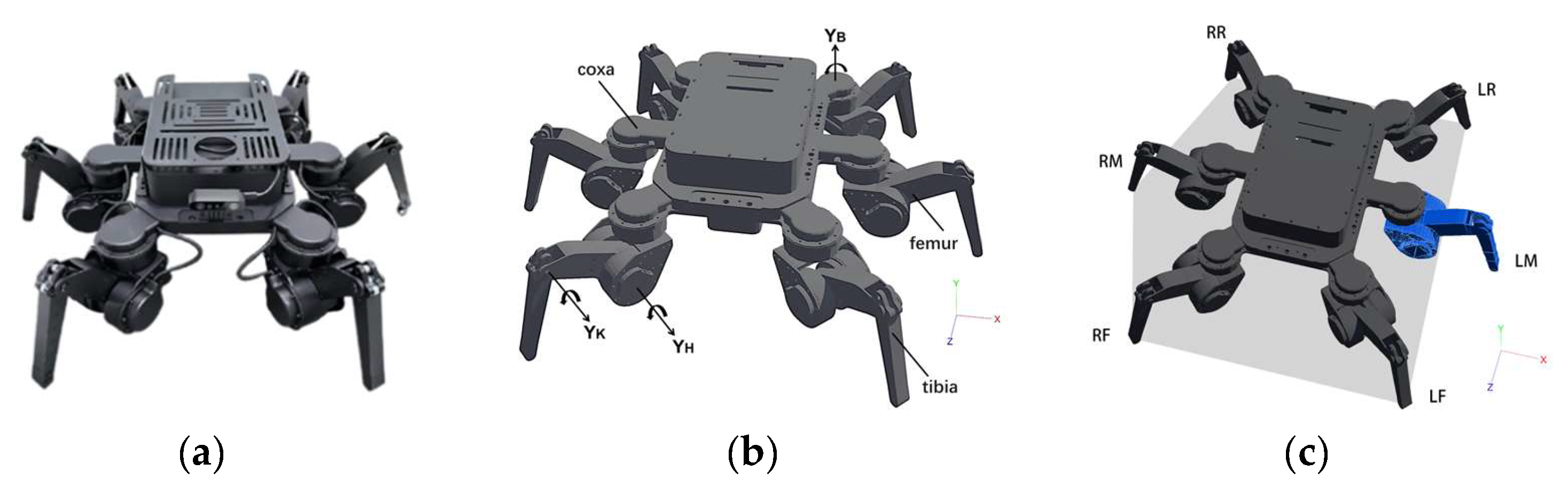
Figure 2.
Schematic diagram of the single-leg kinematic model.
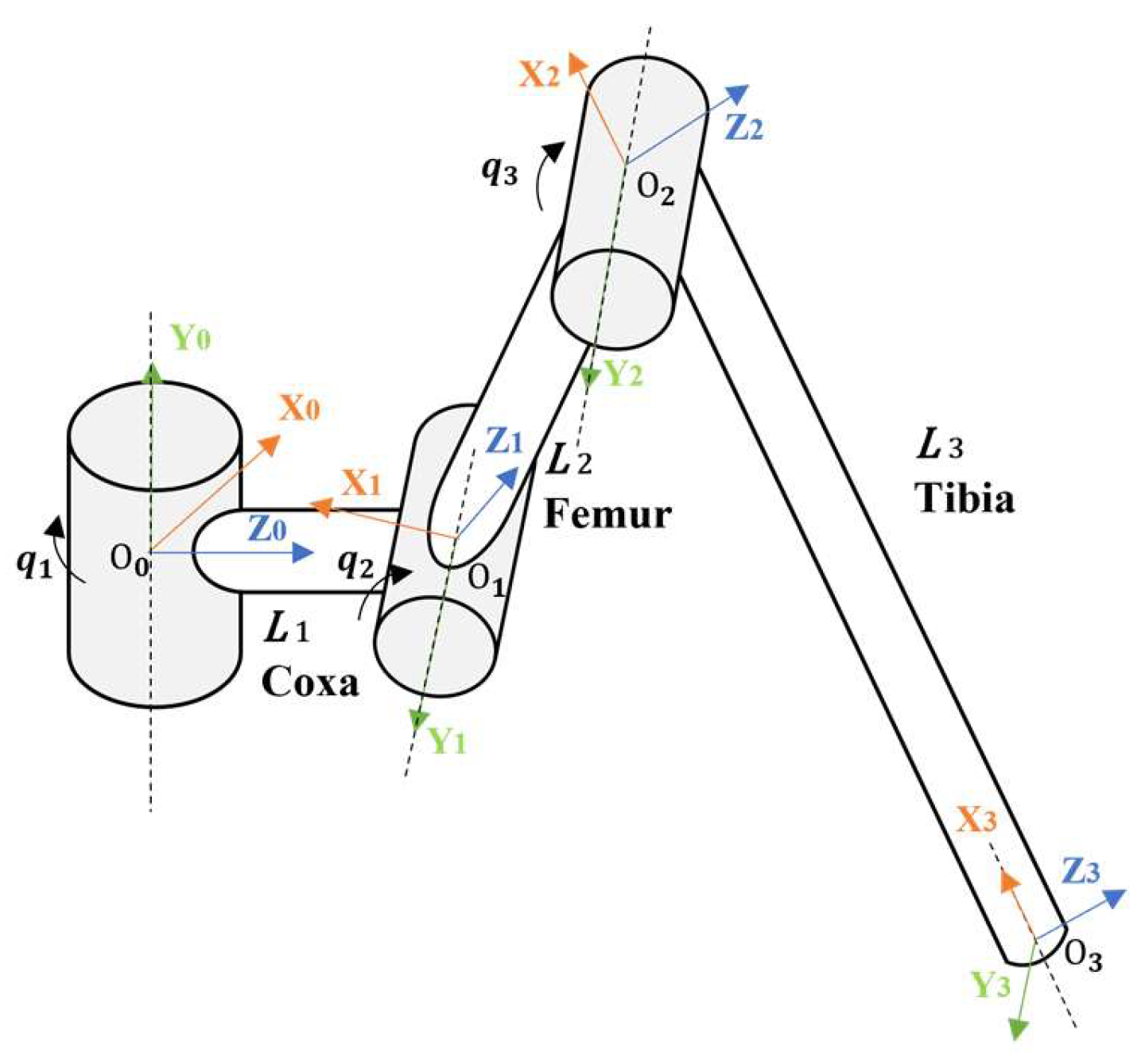
Figure 3.
Schematic diagram of support-polygon distortion and centre-of-mass projection constraint shift caused by the task reserved leg. (a) complete hexapod support configuration; (b) five-legged support configuration; (c) support-margin shift.
Figure 3.
Schematic diagram of support-polygon distortion and centre-of-mass projection constraint shift caused by the task reserved leg. (a) complete hexapod support configuration; (b) five-legged support configuration; (c) support-margin shift.
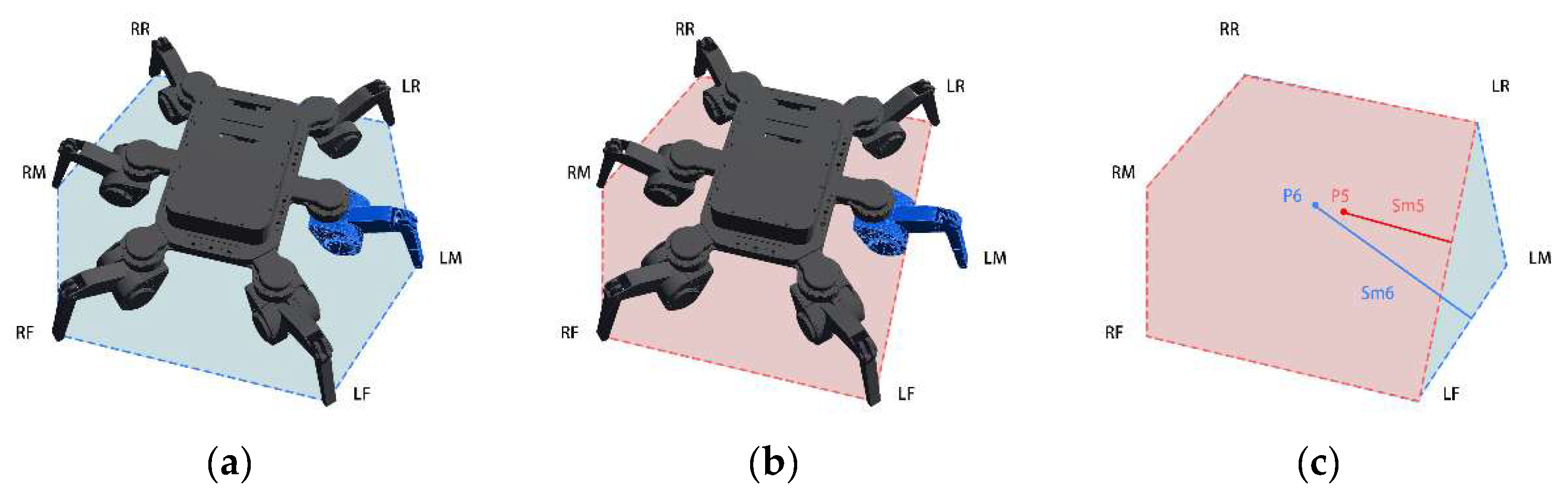
Figure 4.
Control method framework.
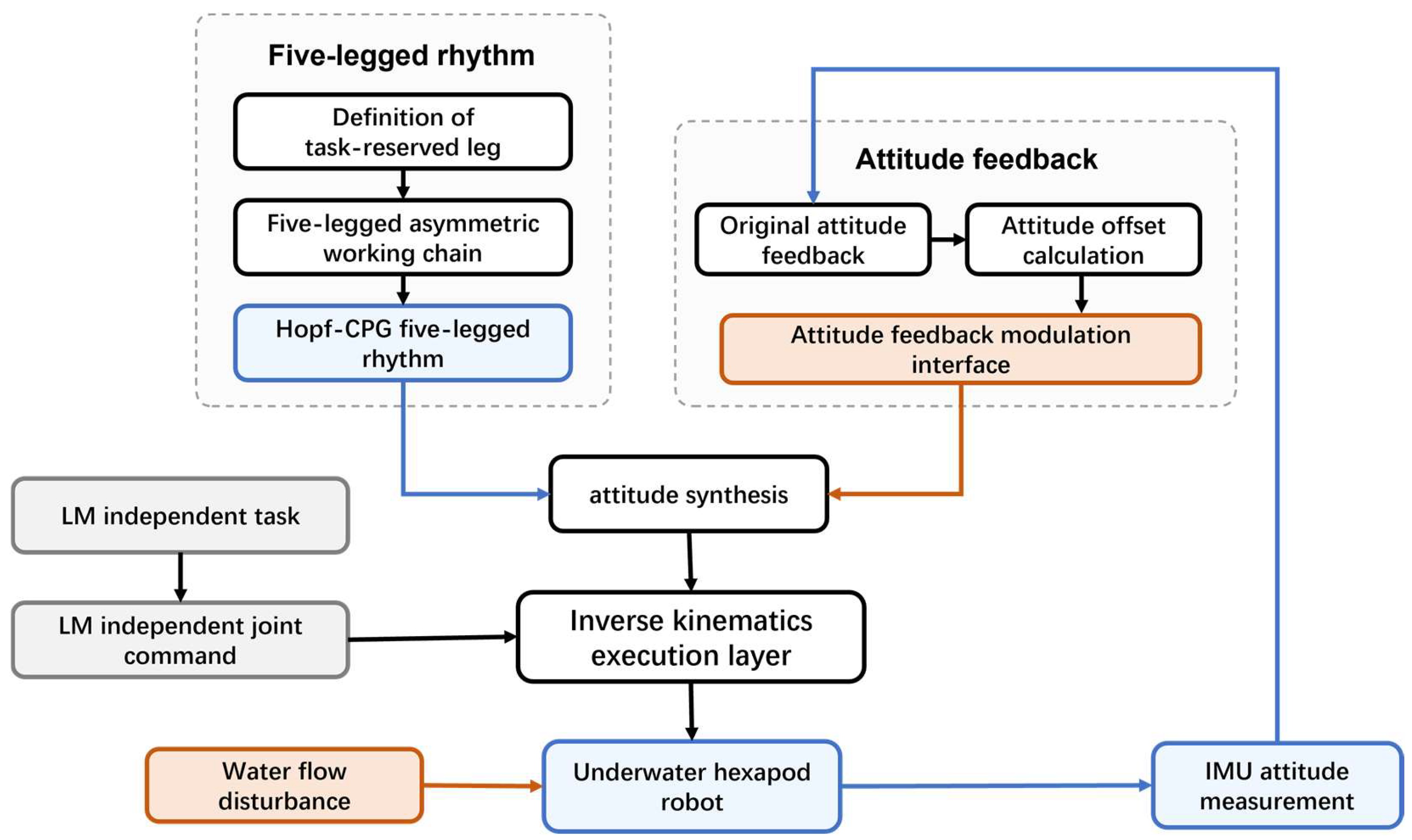
Figure 5.
Phase sequence of five-legged rhythm.
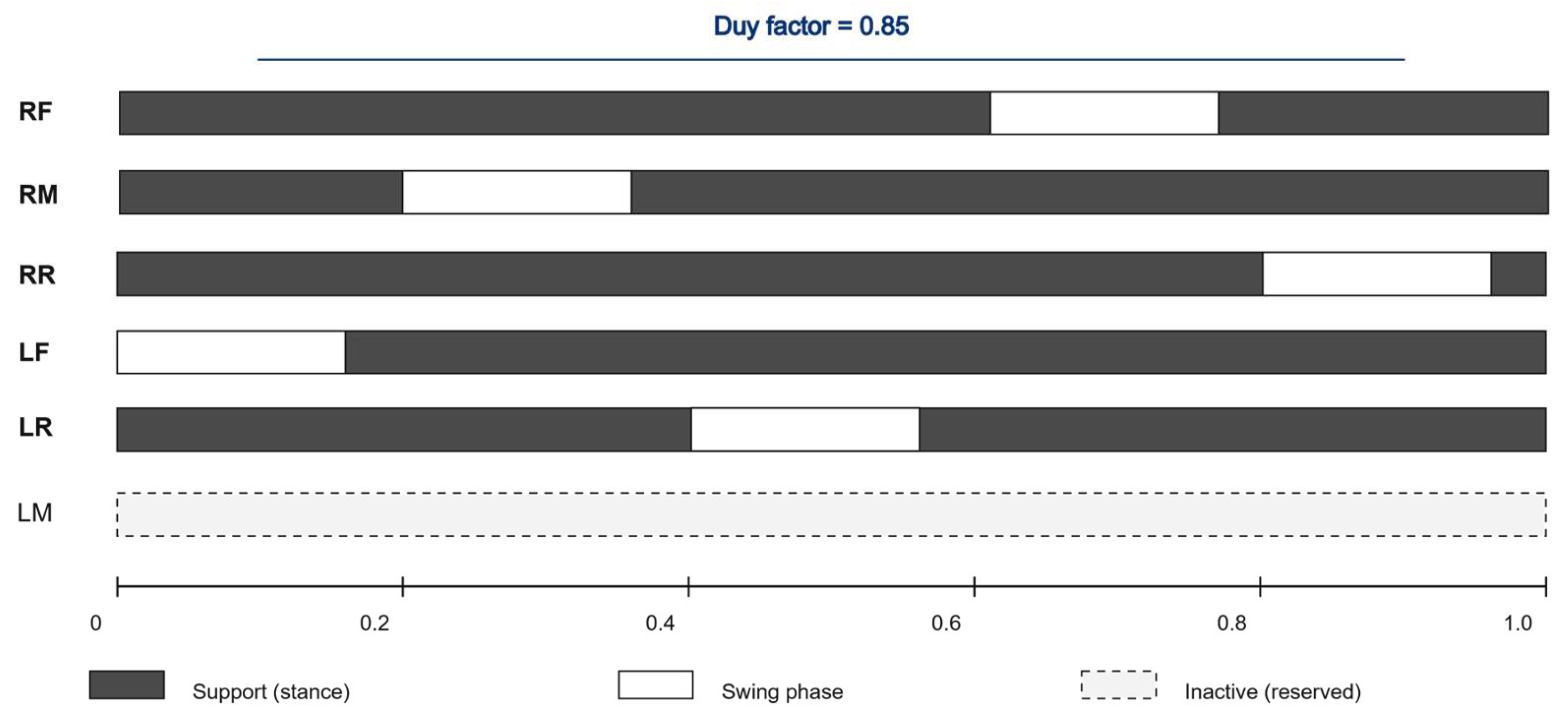
Figure 6.
Low-bandwidth attitude modulation mechanism.
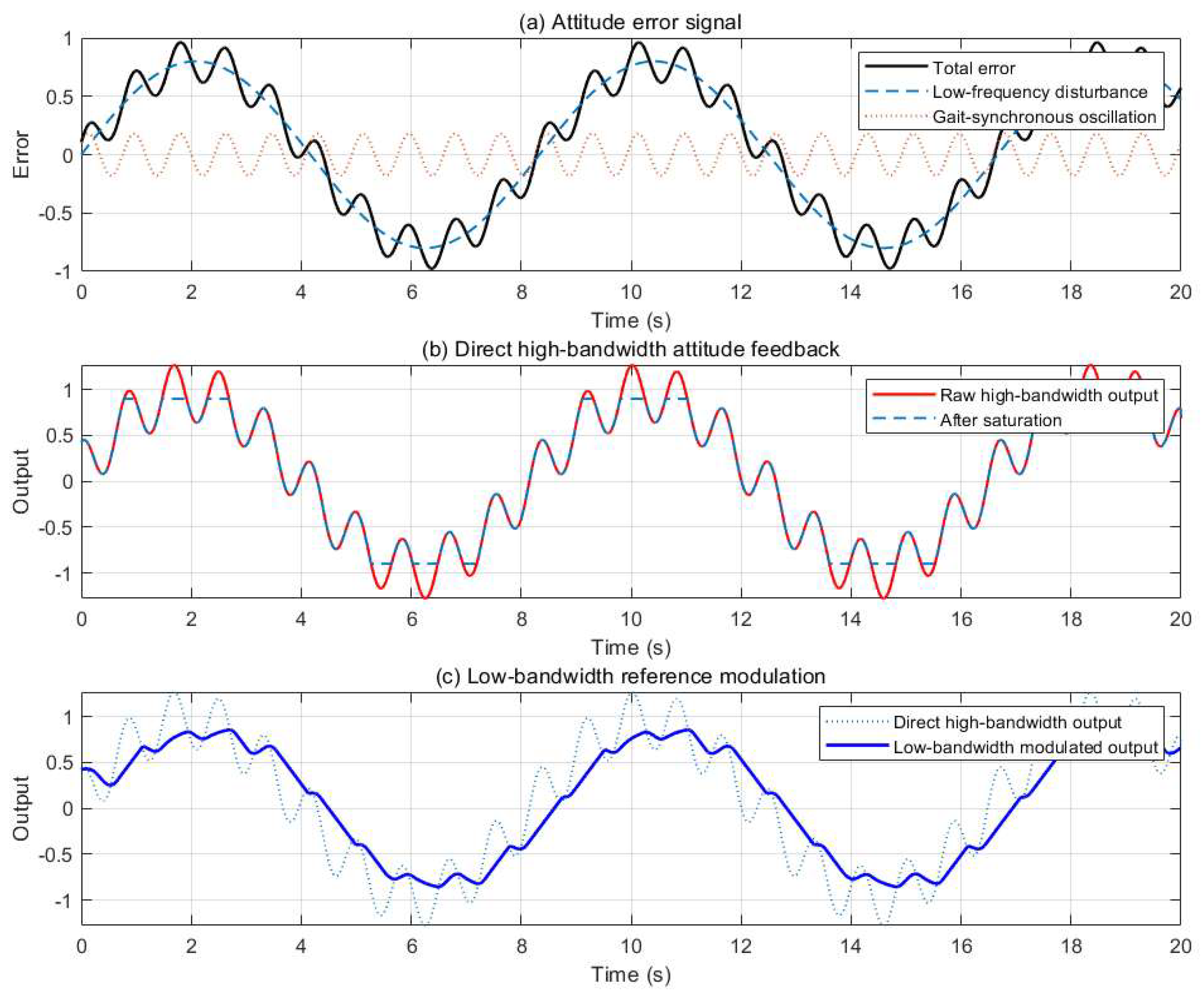
Figure 7.
Webots simulation experiment.
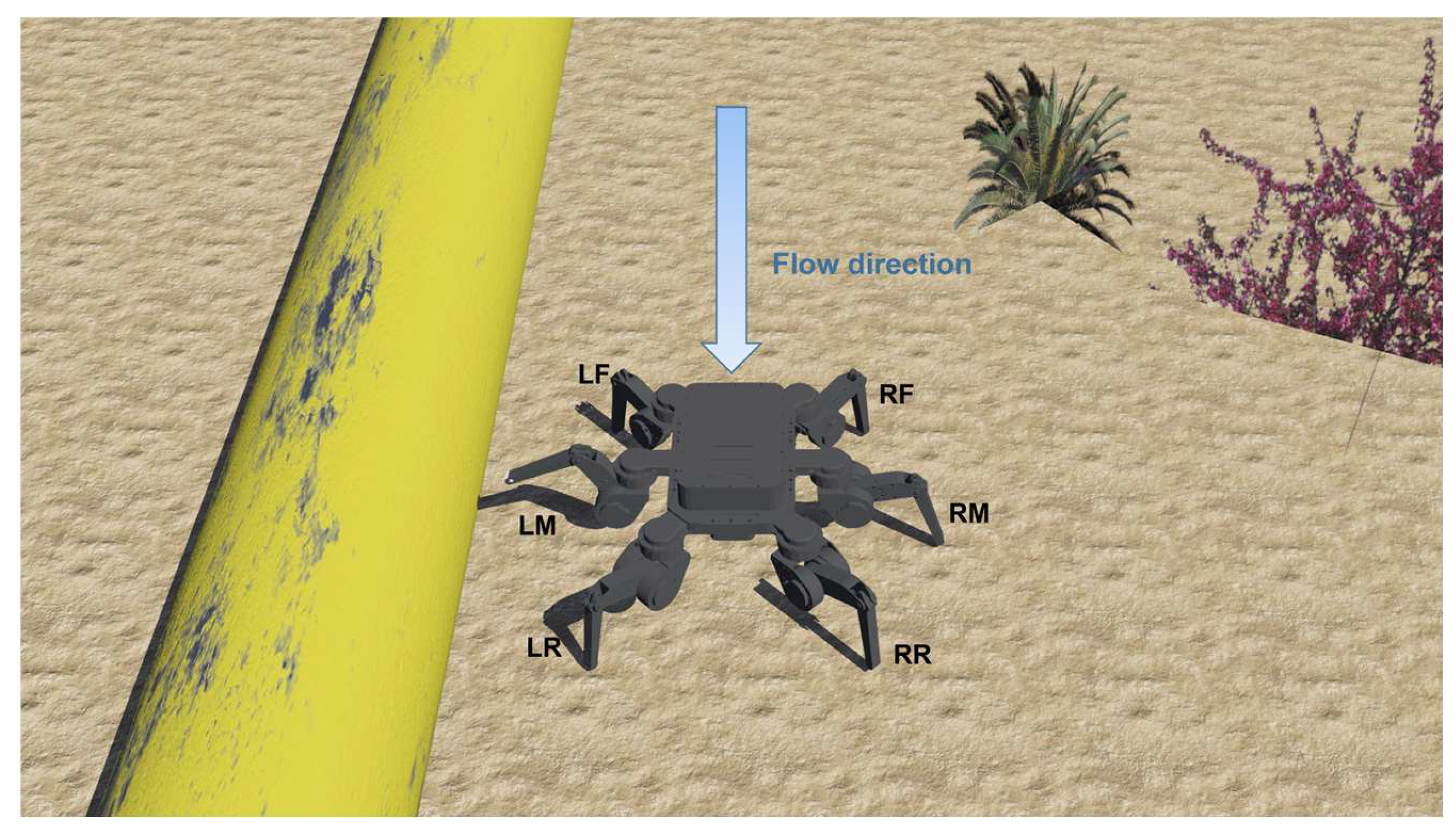
Figure 8.
Experimental Action Sequence of the Hexapod Robot.
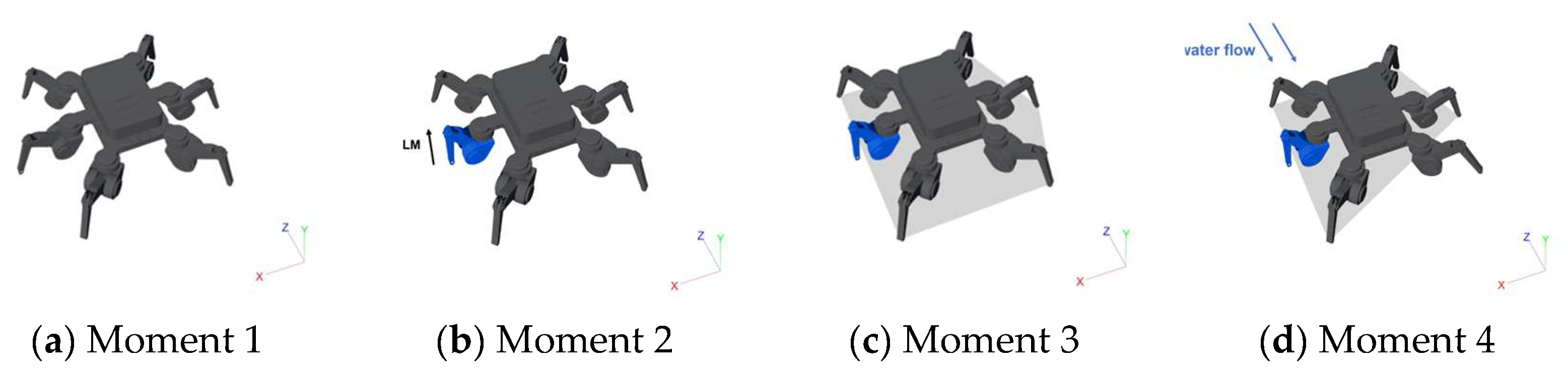
Figure 9.
Roll/pitch time response of B1 at three flow speeds.
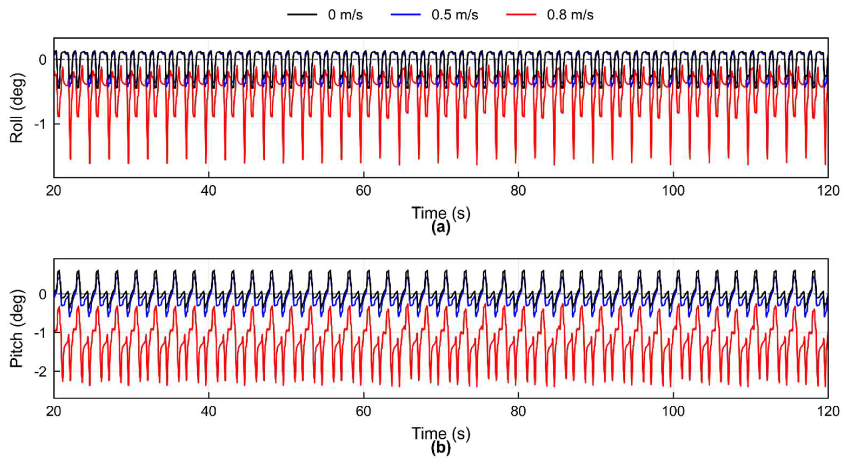
Figure 10.
Comparison of roll/pitch time curves of B1, B2 and Ours at 0.8 m/s.
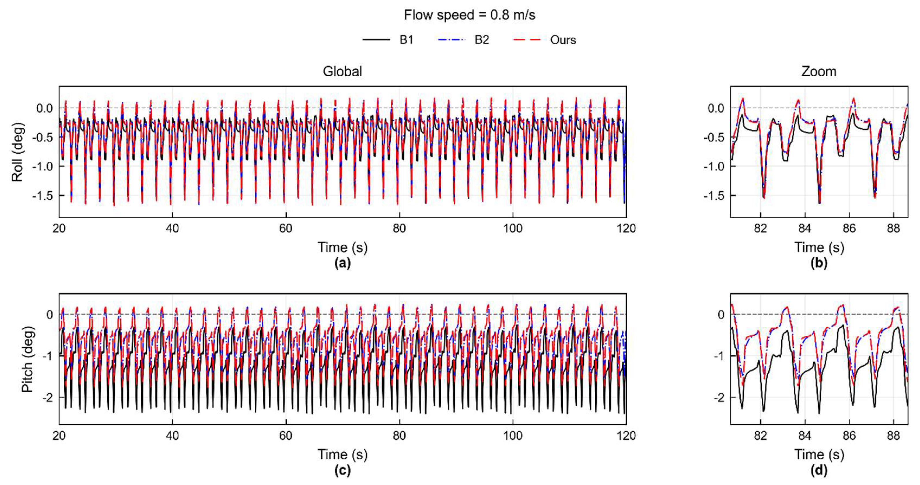
Figure 11.
Comparison of body correction and correction rate between B2 and Ours.
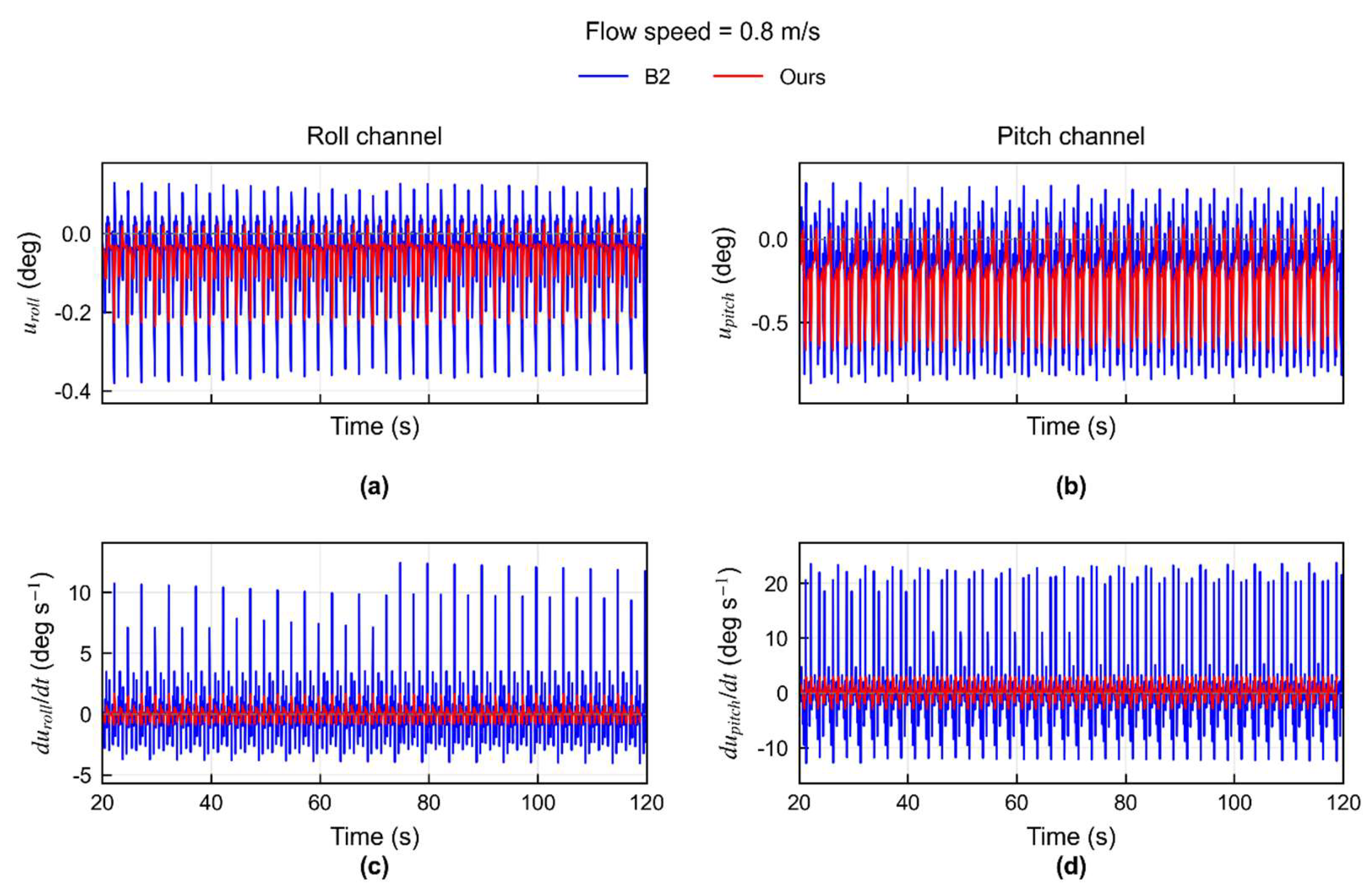
Table 1.
Structural parameters of the robot.
| Parameter | Value |
| Dimension (mm) | 800x750x30 |
| Coxa length (mm) | 50 |
| Femur length (mm) | 150 |
| Tibia length (mm) | 190 |
| Motion range of the hip joint (°) | [-45, 45] |
| Motion range of the knee joint (°) | [-60, 30] |
| Motion range of the ankle joint (°) | [-30, 135] |
Table 2.
Webots water flow disturbance parameters.
| Parameter | Value | Notes |
| Density | 1000kg/m^3 | Close to the density of water |
| Viscosity | 0.001Pa·s | Representative of freshwater at room temperature |
| Stream Velocity | (0,0,-U) | Along the direction of Webots world coordinate system (+ z) |
| Flow speed | 0,0.5,0.8m/s | Static water, medium water flow, strong water flow conditions |
| Reference Area | immersedarea | Calculate the drag based on the submerged area |
| Drag Force Coefficients | (0.525,0.525,0.525) | Equivalent quadratic drag coefficient |
| Drag Torque Coefficients | (0,0,0) | No additional fluid drag torque is applied. |
| Viscous drag Force Coefficient |
0 | No additional linear viscous drag is applied. |
| Viscous drag Torque Coefficient |
0 | No additional viscous drag toque is applied. |
Table 3.
Main simulation parameters.
| Parameter | Value |
| Robot mass | 60 kg |
| Control period | 8 ms |
| CPG basic frequency | 0.4 Hz |
| Stride length | 0.04 m |
| step height | 0.04m |
| Duty cycle | 0.85 |
| Five-legged phase order | LF–RM–LR–RF–RR |
| Task reserved leg | LM |
| Water flow direction | Longitudinal reverse flow against the body |
| Flow speed | 0, 0.5, 0.8 m/s |
Table 4.
Attitude statistics under different flow velocities and control methods.
| Flow speed (m/s) | Method | RollRMS (°) | PitchRMS (°) | Combined attitude RMS (°) | Pitch peak (°) |
| 0.0 | B1 | 0.2041 ± 0.00000 | 0.2507 ± 0.00000 | 0.2286 ± 0.00000 | 0.6176 |
| B2 | 0.1941 ± 0.00000 | 0.2011 ± 0.00000 | 0.1976 ± 0.00000 | 0.4999 | |
| Ours | 0.1993 ± 0.00003 | 0.2148 ± 0.00008 | 0.2072 ± 0.00005 | 0.5208 | |
| 0.5 | B1 | 0.2102 ± 0.00005 | 0.2932 ± 0.00005 | 0.2551 ± 0.00005 | 0.5965 |
| B2 | 0.2027 ± 0.00015 | 0.2368 ± 0.00012 | 0.2204 ± 0.00013 | 0.4780 | |
| Ours | 0.2064 ± 0.00015 | 0.2510 ± 0.00011 | 0.2298 ± 0.00013 | 0.5534 | |
| 0.8 | B1 | 0.6015 ± 0.00000 | 1.3217 ± 0.00000 | 1.0268 ± 0.00000 | 2.3982 |
| B2 | 0.5002 ± 0.00016 | 0.6505 ± 0.00003 | 0.5802 ± 0.00009 | 1.4458 | |
| Ours | 0.5040 ± 0.00015 | 0.6835 ± 0.00004 | 0.6005 ± 0.00008 | 1.5225 |
Table 5.
Control Output Smoothness Comparison between B2 and Ours.
| Flow speed (m/s) | B2 correction rate RMS | Ours correction rate RMS | Reduction rate |
| 0.0 | 0.02393 ± 0.000000 | 0.00676 ± 0.000000 | 71.75% |
| 0.5 | 0.02506 ± 0.000243 | 0.00751 ± 0.000024 | 70.04% |
| 0.8 | 0.06006 ± 0.000002 | 0.01722 ± 0.000002 | 71.32% |
Table 6.
Contact-anomaly ratios under different flow speeds.
| Flow speed (m/s) | Anomaly rate of B1 | Anomaly rate of B2 | Ours anomaly rate | Anomaly rate change between Ours and B2 |
| 0.0 | 0.1008 | 0.0912 | 0.0927 | -1.64% |
| 0.5 | 0.0554 | 0.0560 | 0.0560 | +0.00% |
| 0.8 | 0.2125 | 0.2769 | 0.2606 | +5.90% |
Table 7.
Support-geometry and contact-continuity metrics at 0.8 m s−11.
| Method | Mean static COM margin | Negative-margin ratio | Mean support-polygon area |
| B1 | 0.02506 | 15.66% | 0.07408 |
| B2 | 0.03049 | 10.04% | 0.07807 |
| Ours | 0.02943 | 11.54% | 0.07700 |
Disclaimer/Publisher’s Note: The statements, opinions and data contained in all publications are solely those of the individual author(s) and contributor(s) and not of MDPI and/or the editor(s). MDPI and/or the editor(s) disclaim responsibility for any injury to people or property resulting from any ideas, methods, instructions or products referred to in the content. |
© 2026 by the authors. Licensee MDPI, Basel, Switzerland. This article is an open access article distributed under the terms and conditions of the Creative Commons Attribution (CC BY) license (http://creativecommons.org/licenses/by/4.0/).
Copyright: This open access article is published under a Creative Commons CC BY 4.0 license, which permit the free download, distribution, and reuse, provided that the author and preprint are cited in any reuse.