
Submitted:
07 August 2026
Posted:
07 August 2026
You are already at the latest version
Abstract
The Molten Salt Fast Reactor (MSFR) concept, integrated into the iMAGINE framework, offers a transformative approach to nuclear waste management and fuel cycle closure. However, industrial deployment requires small-scale demonstrators like DEMO (demonstration fusion power plant) to validate reactor physics and safety under realistic conditions. This study investigates the central challenge of sustaining criticality in a 50 MWth demonstrator over a 20-year lifespan, with the innovative challenge to operate without employing a traditional mechanical control system. Using the HELIOS code package, simulations reveal that a reference burner core with 19.9% enrichment experiences a significant criticality loss of over 2600 pcm during reactor lifetime. Several non-mechanical compensation strategies were evaluated against operational goals. Over-feeding fissile material can stabilize criticality but risks deviating from the salt’s ideal eutectic composition. Relying on negative thermal feedback requires temperature adjustments of approximately 130 K, which may be "too challenging" for a first-of-a-kind system due to increased corrosion risks and narrow safety margins. Furthermore, while online salt clean-up of noble metals is vital for chemical validation, its direct contribution to reactivity is marginal. A central novel insight is the identification of a "design dilemma": although increasing core size (reducing enrichment to 14%) sustains criticality through enhanced breeding, it increases fuel costs by 2.5 times and extends the time to target burnup from 20 to about 60 years. Since the primary mission of a demonstrator is to produce high-burnup fuel for analysis quickly, larger cores are counterproductive. results of this study shows that no single method is ideal; instead, either a hybrid approach combining several of the investigated approaches or a future disruptive innovation, such as moderator control for HTGR, is essential to balance reactor physics with practical experimental objectives.
Keywords:
nuclear
; nuclear energy
; molten salt reactor
; fast reactor
; demonstration
; technology transfer
; burnup
; reactivity compensation
1. Introduction
The transition toward low-carbon energy systems has renewed strategic interest in nuclear power as a reliable and scalable 24/7 available component of global expansion strategies. Nuclear energy provides dispatchable, low-greenhouse-gas electricity and is recognised as one of the key contributors to decarbonization alongside renewable sources [1,2]. Advanced reactor systems, particularly fast reactors, are gaining interest, on the one hand due to their capacity to improve resource utilisation and, on the other hand, due to their potential to significantly reduce long-lived radioactive waste inventories. Within this framework, the molten salt fast reactor (MSFR) represents an especially promising technology, offering through the liquid fuel intrinsic compatibility with closed fuel cycles and continuous recycling/clean-up of the nuclear fuel [3,4,5,6].
A key evolution of this concept is represented by the iMAGINE framework, which extends the MSFR approach into a fully integrated nuclear system combining reactor operation, fuel cycle closure, and waste management [6]. Rather than a single reactor design, iMAGINE constitutes a system-level concept that integrates demand-driven salt clean-up through reverse reprocessing, dynamic fuel management through flexible feeding, and direct operation on spent nuclear fuel to minimize waste generation [7]. Central to this approach is the implementation of reverse reprocessing, where key neutron-poisoning elements are selectively removed during operation to maintain criticality and optimize performance [8]. This represents a disruptive shift from conventional fuel cycle thinking toward an integrated and adaptive operational paradigm with new challenges and promises [9]. Despite these advantages, a major limitation remains the lack of operational experience with liquid-fuel fast reactors, as current knowledge is largely based on modelling and small-scale experiments [10].
To address this gap, demonstrator systems such as DEMO are essential to bridge the transition from conceptual design to future industrial deployment. DEMO is positioned as an intermediate development step aimed at validating reactor physics, fuel cycle integration, reactor operation, and safety performance under realistic conditions. Historical demonstrators underscore this role; EBR-II [11] demonstrated integral fast reactor operation including passive safety behaviour, while AVR [12] provided long-term operational insights for advanced reactor systems. International developments further highlight the importance of demonstrators. The MOSART concept in Russia focuses on transuranic management and flexible fuel cycle operation, with explicit emphasis on experimental validation of salt chemistry and materials behaviour [13] reducing technological uncertainty.
A central challenge for fast reactors lies in reactivity control, and control system malfunction among the critical initiating events for accidents [14]. Fast reactors exhibit a low delayed neutron fraction and short neutron generation time, leading to rapid system response and reduced controllability margins. Consequently, control systems themselves may act as initiators of reactivity insertion accident, if not carefully designed. This challenge is further intensified in MSRs due to the transport of delayed neutron precursors with the flowing fuel, which effectively reduces the available delayed neutron fraction [13,15].
As a result, to evaluate all the system parameters in fast reactors, especially MSFRs such as iMAGINE -with their multipurpose intention features- a technology development plan (TDP) based on step-by-step verification & validation (V&V) through experiments looks crucial (as can be seen in the DEMO project). This study will evaluate iMAGINE project features and will identify the necessity of a demonstrator to reduce technological uncertainty in the development ladder of the project. Simulations are focused on criticality preservation during 20 years of operation of the demonstrator without employing mechanical control systems. This is essential to combine in the future closed fuel cycle operation, adaptive control strategies, and experimental validation, thereby addressing both strategic energy goals and fundamental reactor physics constraints.
2. Simulation
2.1. Basic Considerations
The main assumptions were used for simulation and modelling of iMAGINE demonstrator reactor core can be listed as follows:
- ▪ maximum demonstrator maximum power. 50 MWth
- ▪ Target operational time 20 years (3 years at 1 MW, 3 years at 10 MW, 14 years at 50MW)
- ▪ Maximum Uranium enrichment 19.9%
- ▪ Fuel Salt: NaCl-UCl3-UCl4 in eutectic composition 42.5%–17.0%–40.5% molar fraction
- ▪ Cl-37 enrichment 99%
The share between the fuel inside and outside of the core is one of the key parameters for the design of a molten salt reactor where the fuel and coolant are a unity which is moved from the core through the heat exchanger. The basic consideration of the share of fuel amount outside of the core is based on two different studies:
- a)
- how much fuel do we need to move to get the energy transferred
- b)
- how do we deal with the safety, redundancy of heat transfer
point (a) will define the following amount of fuel to be moved; considering the temperature gradient (heat up) of 100K inside reactor core and assumed heat capacity for NaCl-UCl4 50:50 (mole fraction) at 1000 K with 110 [J/(K.mol)] result to a basis for estimation of the required mass flow of ~1 ton/s or a volume flow 1/3 m3/s at a salt density of 3.2 [kg/l].
Point (b) leads to the following consideration based on the EVOL design [17,24] which is foreseen to have 50% of the fuel outside of the core in a system with 16 heat exchangers and pumps. In our case we decided for 2 instead of 16 loops which leads to a guess of 12.5 % of the salt outside of the core.
Both criteria have to be fulfilled with the larger amount to be chosen based on the size of the core. The required critical dimension of the core for each step of the study is based on 3D Monte-Carlo calculations using KENO VI in a multi-group setting [18] based on a simple cylindrical geometry with equal height and diameter. For the simulation, the core is surrounded by a 30 cm reflector on each side. The results are not only used to determine the size of the core but also to determine the leakage for the 2D calculations through the setting of the BSQ operator in HELIOS.
The objective of following simulation is to evaluate the reactivity loss in the core during the planned operational schedule for 20 years as defined above as well as different options for the reactivity compensation without relying on a mechanical control system for burnup compensation or criticality.
2.1. Modelling, Code and Data
The codes and methods description has already been provided in several publications [19, 20 and others]. However, it is adapted to the specifics of this study, and it is essential for general understanding. The HELIOS code system version2.03 with the internal 173 group library [21] has been employed in this modelling. HELIOS is a 2D spectral code with wide unstructured mesh capabilities and a transport solver based on the collision probability method [22] and the Method of Characteristics [23]. The general model is based on the EVOL benchmark configuration [24] which is transferred to a volume corrected 2D HELIOS model, see [19,20], but as described only two loops were considered in this study (see Figure 1). The model is parametrised to allow changes in the core size by just changing one single parameter, which adapts in addition to the core size all in-core discretisation and the outer fuel region proportionally, while the vessel and reflector dimensions are kept constant. Leakage in the third dimension is introduced into the calculation through the insertion of a buckling correction available in HELIOS (BSQ). This value is fixed by a comparison of 2D and 3D calculations as described above. The leakage in the radial direction is directly modelled through vacuum boundary conditions.
The salt system chosen for iMAGINE is based on NaCl-UCl3-UCl4 with the eutectic composition 42.5%–17.0%–40.5% mole fraction. A detailed discussion on the data of the salt system and the rationale behind the choice is given in [26]. The blanket area is filled with steel as reflector, while the protector is based on B4C. The core model dimension is determined in each step through Monte-Carlo calculations. Moreover, U-235 enrichment is limited to max. 19.9%, the Cl-37 enrichment is set to 99% and the operational temperature to 980 K, unless specified differently in the study on the variation of the fuel temperature. The tailings feed used 0.3% U-235 content.
The operational schedule (1 MW, 10 MW and later 50 MW) based on the reference core size is represented through:
- 3 years of operation with a power of 0.083 W/g and the burnup steps 0, 0.05,1,5,10 MWd/tHM repeated for 9 cycles
- 3 years of operation with a power of 0.83 W/g and the burnup steps 0, 0.5,10,50,100 MWd/tHM repeated for 9 cycles
- 14 years of operation with a power of 4.2 W/g and the burnup steps 0, 25,50,250,500 MWd/tHM repeated 42 cycles
The HELIOS code is an industrial standard software which is designed to perform the neutron transport calculations, the burnup calculations, and if requested the cross-section preparation for core simulators. Originally, the HELIOS code was written for the simulation of solid structured fuel assemblies, thus the possibility of online refueling, online reprocessing, and the release of fission gas and volatiles from the core was not foreseen. To deal with these special features required for the simulation of molten salt reactor operation a PYTHON script has been developed [20], which is based on the special features of the HELIOS package.
All input data, which does not change during the whole reactor operation, is stored in a so-called expert input. The changing material configuration is fed into the system through a user input which is re-written in every cycle using a PYTHON script. Within each of the cycles 5 burnup steps are run within the HELIOS calculations. The expert input and updated user input are merged every cycle in the pre-processor AURORA [28], to create the input for the HELIOS run delivering the neutron flux distribution and the burnup. The results are evaluated in the post-processor ZENITH [29]. On the one hand, here it is decided which elements are reduced or increased and to what extent. On the other hand, the data for the new user input is created in ZENITH using the information to be fed back into the next cycle by the PYTHON script (see Figure 2). Theoretically, it would be possible to simulate a molten salt reactor to high precision by using small time steps in this loop.
In a real MSR two different time scales for the salt cleanup will take place based on two different processes, 1) the release of gaseous and volatile fission products with a comparably short acting time, and 2) the online salt cleanup for the dissolved fission products with a significantly longer acting time, both processes with their own efficiency. The cycle time for each power regime is kept constant through the adopted burnup steps. The cycle length determines the complete removal of gaseous and volatile fission products (the elements 18, 35, 36, 53, 54, and 85 are not carried forward through ZENITH). The dissolved fission products can be removed based on a variable cleaning efficiency set in ZENITH, providing the opportunity to adopt the share of salt to be cleaned elementwise for all considered elements.
The use of the described process has already been validated and used in several peer-reviewed publications [20, 30 and others]. Over time, the modelling and simulation quality has improved through the new code versions, the increased computational power, and the related number of energy groups, which has been now set to 173.
However, some approximations still have to be accepted. There is no fuel salt movement with a cycle, the materials are only re-distributed when a new user input is defined. A LWR spectrum is used for the within group weighting of the master libraries. However, this error will be significantly reduced by the increased number of groups. Comparisons with other codes were conducted with the EVOL benchmarks [25], moreover, in a fast reactor isotope accumulation test against SERPENT [31], as well as comparisons with SCALE/POLARIS [26] were all shown good agreement. This is what is currently available in terms of modelling techniques and solvers; for a final validation a real reactor physics experiment would be required, or ideally the demonstrator where the first studies are presented, here.
The approximations and the use of the HELIOS code package seem to be adequate for the accuracy level required for first studies of a new system. The results on isotope production and criticality evolution have been evaluated in earlier publications [32] and a detailed comparison to SCALE/Polaris is given in [18]. For a more detailed design of a demonstrator, we will recommend a well-balanced combination of deterministic and Monte-Carlo calculations, to take advantage of the best of each method.
These studies aim to evaluate the reactivity loss in the core during the planned operational schedule for 20 years. This will be combined with the investigation of different approaches to compensate for the criticality loss due to burnup without the demand for a burnup compensation through an explicit control system by using different physical effects.
3. Results and Discussion
Following parameters were used for the base case simulation;19.9% U-235 enrichment to respect HALEU standard and, 99% enrichment of Cl-37. The 3D Monte-Carlo determined diameter and hight of the core is 190 cm if the core is surrounded by a 30 cm steel reflector on all sides. The 3D result for the system criticality and core size led to an initial keff of 1.003503 ± 0.00001 as steady state value by KENO. This results to a BSQ setting of 5.387046E-5 for the HELIOS model to achieve the identical keff value in the used 2D model. For the reference case no feeding of any heavy metal is considered as well as no cleanup besides the release of the gaseous and volatile fission products at the end of each cycle.
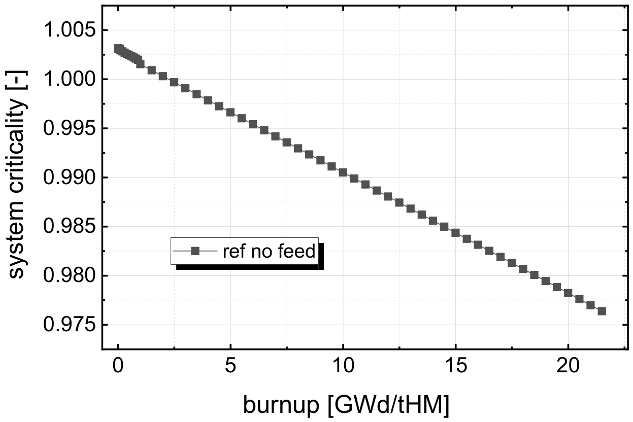
The system criticality over burnup using the averaged keff value for each cycle, given in Figure 1 indicates a criticality loss of more than 2600 pcm over the supposed operational time. The figure shows a clear burner behaviour with a almost linear reduction of criticality related to the energy produced. No real effect of breeding is visible within this curve. The high density of values at the beginning reflects the very slow burnup of the fuel in the first 3+3 years where the system is planned to operate on very low burnup and power.
Figure 3.
Criticality over burnup for the demonstrator core as reference system without feeding provided.
Figure 3.
Criticality over burnup for the demonstrator core as reference system without feeding provided.
In contrast to the criticality versus burnup figure, the criticality over operational time, Figure 4, shows the different speed in which the burnup is accumulated due to the different operational power. The three different power settings are indicated in the figure to better understanding. For each power setting the observation is the same as in Figure 3, the criticality decrease is almost exactly linear, while the gradient of the criticality change is defined through the power and thus the energy released by the fuel. Combining the information from both figures, it can be stated that in 20 years of operation roughly 22 GWd/tHM energy is extracted from the fuel or an overall energy of a bit more than 260 GWd is extracted from the fuel over the whole lifetime. The criticality loss in the 1 MW phase is 45 pcm and in the 10 MW phase it is 150 pcm, which means there is nothing to worry regarding core criticality loss in the first 6 years of operation
In the first step to improve the performance and to reduce the criticality loss, the core will be provided with a feed which aims to keep the heavy metal content as constant in the core. The reference case will be compared to the case with feeding of tailings (0.3% U-235) and the case with feeding of 19.9% enriched Uranium as provided for the startup of the core.
Figure 5 demonstrates the settings for the heavy metal feed. The aim is to keep the heavy metal content, a summation of Uranium and Plutonium, in the core constant by adding Uranium with different isotopic compositions. The approach here is, to keep the fuel as close as possible to the eutectic condition of the salt. However, for a deeper understanding it is worth to look into another option, too, that is ‘How much feed would be required to keep the criticality level?’ No feed would lead to a decrease of the heavy metal content by ~2.5% which would lead to a reduction of the HM content from 57.5 % to 56% leading to a deviation from the eutectic composition. To compensate for the criticality loss by over feeding the reactor to assure a constant criticality value, will lead to an increase in the HM content by 4.3% or a deviation from the ideal 57.5% to 60% HM within the salt.
Based on the change in the heavy metal content and the resulting deviation from the eutectic, this over feeding option will require a deeper investigation to understand the effects on the thermo-physical properties caused by the deviation of the salt composition change away from the eutectic composition.
The criticality for the investigated cases over the operation time, Figure 6, shows that keeping the overall HM content, just by adding tailings, does not have a major influence in such a small burner core. This is in strong contrast to earlier investigations of a full size homogeneous iso-breeder core, where keeping the HM content, and thus the amount of available fertile material constant is essential. In the small core, only feeding of fissile material, in form of the19.9% enriched Uranium, supports the criticality. However, just replacing the reduction of the HM content caused by the fission process is not sufficient. This indicates that fission take mainly place in the fissile material and the reproduction of fissile material through breeding is not sufficient. The replacement only allows to reduce the criticality loss by a bit more than 1000 pcm. Two possible approaches would be possible to solve this problem, either the make-up through substantially higher enriched fuel, which would cause some proliferation issue since the feed would not be within the limits of HALEU anymore, or the over feeding with 19.9% enriched Uranium fuel as used in the initial core which will lead to the already described increased HM content. This second approach is given in through the green down facing triangles which show only a very minor change in criticality over the whole operational period, which is related to the calculation method and the resulting approximations. However, the quality of the results is in this case clearly within the expected and demanded calculation accuracy.
The concentrations of the fissile material were depicted in Figure 7 confirms the very small contribution of breeding to the fissile material balance. In the first 6 years almost no Pu-239 breeding (see open symbols) takes place, and even in the full power operation period the build-up of Pu-239 is very limited. There is no real difference visible between the different cases studied. The comparison with the reduction of U-235 makes clear that the breeding cannot compensate the loss of fissile material due to the fission process. The analysis of the U-235 content gives the following picture: the no feed case and the tailing feed case show almost the same decrease which should not surprise since the U-235 content in the tailings is almost negligible. The compensation of the heavy metal loss through feeding 19.9% enriched Uranium helps to reduce the reduction of the fissile content to some extent, but is still not sufficient, reflected through the reduced criticality loss, compared in Figure 6. The over feeding case shows that there is substantially more U-235 required to keep the overall fissile content to a level to keep the system critical. The still existing limited drop of the U-235 content is in this case compensated through the limited build-up of Pu-239 as leading fissile material bred through the full power operation. In general, these results clearly confirm that a small fast reactor core with a comparably high initial enrichment is far from a breeder configuration and has to be considered as a burner with a comparably low conversion ratio which should be kept in mind when discussing small modular reactors with a fast neutron spectrum.
The data deliver in addition some important basis for the safety and security regulation based
on the Nuclear Security Recommendations on Physical Protection of Nuclear Material and Nuclear
Facilities, CATEGORIZATION OF NUCLEAR MATERIAL [35] since it allows a first guess on the Pu
amount which will be produced during operation. The core contains at the end of operation ~120kg
Pu-239 which translates to a Pu concentration of ~1%, thus comparable to LWR fuel. This means the
facility would fall under Category II of the CATEGORIZATION OF NUCLEAR MATERIAL,
containing more than 10 kg of Uranium with an enrichment between 10 and 20% U-235. Even during
operation, the facility should stay within Category II even if the limit for Plutonium, less than 2 kg, will be exceeded. We come to this conclusion, since the limit values are given for unirradiated fuel,
which is defined as Material not irradiated in a reactor or material irradiated in a reactor but with a
radiation level equal to or less than 1 Gy/h. The reactor will contain more than the specified 2 kg of
Pu, but the fuel is irradiated in the reactor and is expected to have a higher level of radiation than 1
Gy/h.
The thermal reactivity feedback effect could deliver another solution for the reactivity compensation for a case without external control system of reactivity compensation. In general, molten salt fast reactors have a strong negative feedback effect [33,34], caused through the loss of fissile material from the core if the control volume is kept constant. The feedback effect has been calculated for the temperature change from 930 to 980 K which leads to a density reduction from 3.28 kg/l to 3.23 kg/l following the formula given in [35]. The temperatures for the study have been chosen to lie within the temperature range given for the density correlation (930 K-1030 K), even if future operation of the demonstrator is planned at much lower temperatures, ideally between 673 K and 773 K. The temperature reactivity effect combining the Doppler and the density change is for the given system at begin of life is slightly less than 13 pcm/K with negligible variation over one burnup cycle. Base on this value, a strategy has been developed to keep the core critical within the expected level of accuracy, shown in Figure 8. For comparison, the base case with 19.9% enriched compensation feed is given. For the calculation, the temperature has been changed stepwise, each time after 9 cycles. Here, an approximation is required since every temperature change demands a change in the expert input and thus a restart of the whole calculation chain. The density change has been implemented in a continuous way through the 9 cycles based on the density multiplier in HELIOS. The detailed data on the temperature steps, the related densities and the derived density multiplier are given in Table 1. The salt density curve is indicated in Figure 8 with the scales on the right axis. It shows the almost perfect mirror of the criticality curve. The very limited effect of the Doppler effect is visible through the very small steps which appear after every 9 cycles, maybe best visible after year 12.
The initial criticality is achieved at a temperature of 1003 K and reduced density of 3.208 kg/l. The following temperature steps given in Table 1 Have been determined through the known feedback effect and the calculated criticality loss. The table indicates that for the combination of the heavy metal replacement with 19.9% enriched Uranium and the use of feedback effects, there is still a temperature change of 130 K required for compensating the reactivity loss. This number seems to be too high for a demonstrator where the heat up of the salt is planned to be in the range of 100 K. Considering the melting point of the salt at 611 K, a realistic safety margin to solidification of at least 50K, a reasonable lower limit would be 673 K. The compensation would then lead to an upper limit of about 900 K, which seems to be too challenging for studying a widely unknown system in a demonstrator. In addition, increased operational temperatures will lead to faster corrosion rates, thus should be avoided unless sufficient experience is accumulated. Unfortunately, in the case of the reactivity compensation, the highest temperatures would be required at beginning of operation where only very limited experience will be available.
To increase the effect of the burnup compensation and to reduce the required temperature change, the system could be supported through a first level of salt cleanup. The first target would be to separate noble metals, on the one hand due to their high shielding and the related reactivity effect [37] and on the other hand due to the limited solubilities which will allow a physical separation either through cold trapping or through filtration. The boundaries are here the concentrations of the leading noble metal Molybdenum for the initiation of the clean-up, with the set limit of ~400 ppm as initiation value and a lower limit of 200 ppm for the strength of the clean-up to emulate the decrease of the efficiency at low concentrations, since we are facing here a co-extraction based on physics. Based on these requirements, the clean-up will be initiated in the restart of the density and temperature change after cycle 27 and comes the first time into action at the end of cycle 28 due to way the script and the cycles are set up, see Figure 2. The evolution of the concentration of the relevant noble metals involved in the clean-up (Mo, Ru and Pd) is depicted in Figure 9 – only these elements are partly cleaned from the salt in the simulation. The dashed line shows how the concentrations evolve without clean-up, while the full lines indicate the concentrations evolution with clean-up. Following the set boundaries, it is visible, the Mo concentration is reduced through clean-up after the Mo concentration of 400 ppm is achieved and the strength of the cleaning is adopted to lead to an almost asymptotic concentration of 200 ppm. The concentration of Ru and Pd is reduced accordingly, but on a significantly lower level.
The combination of temperature changes and clean-up has been optimized to hold the criticality in the same way of temperature changes only, see Figure 10. However, already the study of the salt density over the operational time shows that the effect of the cleaning of the salt is rather limited. The final density is only less than one percent lower, which reflects that the temperature at the end of operation will only be a little higher. The detailed comparison of the data given in Table 2 and Table 1 shows that the final temperature is only 13 K higher than without the clean-up. This result indicates that the clean-up will not have a massive influence. However, it could still be of high interest to test potential clean-up methods in a later stage of the operation when the concentrations of fission products have reached a level which is sufficiently high. The potential first technology for test could be based on physical separation exploiting the low solubility of the noble metal fission products which have the strongest influence on the system criticality.
The last and surely most powerful method for the compensation of the criticality loss due to burnup is increasing the core size [37], or the initial enrichment which defines the correlated core size. It has already been proven that the salt system can achieve self-sustained breeding at a certain core size. The change of the core size in the case of DEMO can be very efficient since three effects will amplify each other:
- An increased core size requires a lower initial enrichment
- The lower initial enrichment leads to a higher amount of fertile material, which will enhance breeding
- The difference between the initial enrichment and the maximum allowed enrichment (19.9%) will increase with increasing core size
- Less neutron leakage
However, increasing the core size will come with some negative drawbacks:
- Increased cost for fuel and the core system
- Reduced final burnup of the fuel due to the larger fuel amount or
- Demand for a significantly higher power to achieve the identical target burnup after 20 years of operation
Four different initial enrichments are studied, the reference 19.9% will be compared to 18%, 16%, and 14% U-235 enrichment. The correlated core dimensions have been determined through 3D Monte-Carlo calculations leading to radii of 90, 107, 124, and 150cm for the cylinder with equal hight and diameter surrounded by a 30 cm thick reflector. The determined criticality of the MC calculation is used to determine the third-dimension leakage for the HELIOS studies, as described in codes and methods.
The criticality over burnup curve for all 4 cases, see Figure 11, meets the expectation; the lower the initial enrichment and the resulting increase of the core size enhances breeding and at a certain threshold, slightly above 14% the core can be kept critical with the replacement of the burnt Uranium with 19.9% enriched material. However, it has to be kept in mind that this result is normalized on the fuel amount. Thus, the curves which look quasi-identical on the x-axis will run on significantly different time scales in the case of identical power.
Figure 12 clearly shows the described effect. The time required to accumulate the target burnup significantly increases (form 20 years to almost 30, and 45 years and finally to nearly 80 years) for the cases with lower initial enrichment due to the strong increase in the fuel amount in the system in the case of an identical core power. This effect will surely be limiting for DEMO, since accumulating target burnup and a reasonable fission product load are key outcomes which have to be delivered by DEMO. Burnup and fission product accumulation are the basis for creating an understanding of the changes in the salt and the resulting effects during operation. In addition, the fuel with fission product load will be the basis for chemical clean-up studies, another essential outcome of the operation of DEMO.
A first test indicates how far each system is away from criticality and determine the feed which would be required for holding the system critical over lifetime. The required enrichment of the feed should go down with increasing system size. Table 3 confirms this expectation: a feed of roughly 45% would be required to keep the reference case critical, which indicates how much fissile material is really burnt during operation. As expected, the required enrichment drops to 37%, 29%, and finally to below 20% which coincides with the largest system based on 14% initial enrichment. The effect clearly indicates that the system gets more efficient in the fuel use with increased size, which is mainly an effect of the decreased leakage in larger systems and the related improvement of breeding.
For deeper analysis of the breeding, the analysis of criticality over burnup, see Figure 13 is the first point of consideration. This way of presentation makes it much easier to compare the different cases, but it has to be kept in mind that the curves will run at different temporal speeds.
The initial load of U-235 per control volume is decreasing with the initial enrichment as input value, so the correlated system size increasing system size. The reduction of the U-235 concentration over the burnup is almost independent of the system size. The comparison of the BOL content to the EOL content indicates that the concentration falls in the reference case to 90.7%, in the other cases to 89.8% (18% enr.), 88.7% (16% enr), and 87.4% (14% enr), respectively. In contrast, there is clearly more Pu bred in the largest core with the lowest initial enrichment. The comparison of the EOL Pu content to the reference case shows an increase by 14%, 31%, and 52% with decreasing initial enrichment and increasing core size.
The analysis of the fissile nuclide number densities over the operational time, see Figure 14, shows how much the processes are slowed down in correlation with increasing core size. The larger systems behave much more smoothly since the power per unit volume decreases significantly due to the strong increase in the core volume. When correlating the number density with the volume, it becomes clear why the increased Pu concentration is such important for the burnup behaviour of the largest core. Not only is the number density increased by ~50%, but also the core volume is strongly increased by a factor of 4. Together, this lead to an overall increase in the Pu amount by a factor of two, but this has to be considered keeping in mind that this Pu amount will be formed in an operational time of almost 80 years. This is not what is expected to be delivered in a demonstrator.
The results shown in Figure 12 and Figure 14 describe the dilemma of the design of a demonstrator for a new technology. The core aim is to deliver results from power production as quickly as possible, especially a reasonably high burnup of the fuel. Fuel burnup is one of the key results, since it is responsible for all changes in the fuel which are on the one hand to be studied in such a demonstrator. On the other hand, the formation of the spent fuel configuration will be the key for the evaluation and testing of potential fuel clean-up technologies. Spent nuclear fuel is almost impossible to create as a surrogate since it is formed out of 90+x different chemical elements in changing concentrations, depending on the reactor type, the neutron spectrum, the fissile material and the power density due to the very different half-lives of the formed isotopes.
Keeping these facts and expectations in mind the results have been correlated with the reactor sizes calculated as starting values. Table 4 gives insight into the core volumes and the resulting fuel and heavy metal masses and the estimated Uranium costs based on the estimation of the Nuclear Fuel Cost calculator (https://whatisnuclear.com/enrichment.html) using the standard settings of the page. The decrease of the initial enrichment and the resulting increase in the core size will allow to reduce the reactivity loss during the lifetime as expected. However, this change comes with different drawbacks, first of all the core size and with this the required fuel and heavy metal mass increases by a factor of 4 for the case which is stable in criticality over operational time. Looking into the cost, the difference is not as big, since the increased amount of fuel is counteracted by the decreasing cost of enrichment, 14% instead of 19.9% for the reference case. Nonetheless, the fuel cost for the final core would increase by a factor of ~2.5, which would be a real challenge for the financing of the fast reactor demonstrator where the fuel is one of the key cost drivers.
To get a deeper understanding of the situation, Constant operational time with the required power versus constant power with variable operation time which are required to achieve the identical target burnup of 22 GWd/tHM are presented in Table 5 and Table 6. To achieve the identical burnup in all cases the power would have to be increased form the original max. 50 MW to more than 70 (18% enr.), to more than 110MW (16% enr.) and in the case of the system which keeps the system critical almost 200 MW. This power would not be reasonable for a demonstrator; thus, the solution could be only in a compromise with lower power and decreased target burnup. In the case of a constant system power, the operational time to achieve the target burnup increases form 20 years to 26, 37 and finally 61 years, (see Table 6) which is definitely to the preferred solution for a demonstrator where results are expected to be delivered on an as short as possible operational time. Would a compromise be chosen with reduced burnup, the cases would lead to reduced criticality loss after 20 years. The reference case has a reactivity loss of 1636 pcm already in the 18% case the reactivity loss would be reduced about 750 pcm, but the burnup would only be about 14 GWd/tHM. In the 16% case, the criticality drop would be only about 192 pcm, thus at a compensable level, but the final burnup would drop to about 9 GWd/tHM which would limit the quality of the results which could be gained from the fuel analysis as well as the operational experience due to the limited changes of the fuel composition and thus the much reduced challenge on the chemical reactor balancing system. Finally, in the 14% case, no criticality loss takes place, but the final burnup 5GWd/tHM as result of the 20-year operation.
The results have shown that there are different methods for compensation of the reactivity loss without relying on a classical control system for reactivity compensation, but that each of the solutions found will come with some drawbacks. For a future reactor, it is on the designer to identify the ideal solution which maybe could be a combination of different methods, based on the presented results.
4. Conclusions
Demonstration and thus the design, licensing, and operation are one of the core gaps of fast molten salt reactor technology, but this will come with some special challenges.
Sustaining criticality in a small-scale MSFR demonstrator like DEMO without an active reactivity compensation system (avoiding a main accident initiator) reveals a fundamental conflict between theoretical reactor physics and practical operational goals. While the smallest possible reference 19.9% enriched burner core faces a significant criticality loss of 2600 pcm over 20 years, every proposed compensation strategy introduces some technical or economic compromises.
Over-feeding fissile material is the most direct solution but risks operational instability by forcing the salt composition away from its ideal eutectic state. Conversely, relying on negative thermal feedback is physically sound but practically looks "too challenging"; it requires a 130 K temperature adjustment that risks accelerated corrosion at high temperatures and salt solidification at lower margins. Furthermore, while online salt clean-up of noble metals is essential for validating chemical processes, its impact on reactivity is "rather limited," offering only a marginal 13 K temperature relief.
The most significant critique lies in the most promising and straight forward core enlargement strategy. While increasing core size and reducing initial enrichment to 14% effectively sustains criticality through enhanced breeding, it creates a "design dilemma". This configuration increases the already very high fuel costs of a fast reactor by a factor of 2.5 and extends the time to reach target burnup from 20 to about 60 years. Since a demonstrator's primary mission is to provide reasonably high-burnup fuel for analysis as quickly as possible, these larger cores are fundamentally counterproductive.
Ultimately, no single concept mentioned and studied in the manuscript is ideal. The transition from the large conceptual MSFRs of the iMAGINE framework to DEMO requires a hybrid approach that balances these trade-offs, likely necessitating entirely new innovations, such as moderator control as invention created for HTGR, to bridge the gap between sustaining criticality and achieving timely experimental results. Thus, a future step should be to innovate, to propose and study new solutions for controlling the criticality loss. This could maybe be possible though some engineering approaches or through allowing a decreased final burnup but providing accelerated burnup probes which will create a better understanding of the future fuel behaviour to be expected as well as to produce samples for studying clean-up.
References
- Nuclear Technology review 2025, International Atomic Energy Agency (IAEA) GC(69)/INF/9. Vienna. Vienna.
- Five Reasons the Clean Energy Transition Needs Nuclear Power. International Atomic Energy Agency (IAEA) (2026), Press release | Distributed by Public on 27/01/2026 10:18 Vienna. 10:18.
- Merk, B.; Litskevich; Bankhead, M.; Taylor, R. (2017) An innovative way of thinking nuclear waste management – Neutron physics of a reactor directly operating on SNF. PLoS ONE 2017, 12(7), e0180703. [Google Scholar] [CrossRef] [PubMed]
- Pitois, H.; Heuer, D.; Laureau, A.; Merle, E.; Allibert, M.; Delpech, S. A Closed Fuel Cycle Option Using the MSFR Concept with Chloride Salts and the U/Pu Cycle. GLOBAL 2022 Conference.
- Guidez, J.; Merle, E.; Heuer, D.; Bourg, S.; Campioni, G.; Allibert, M.; Delpech, S. Molten Salt Reactor to Close the Fuel Cycle: MSFR Multi-Recycling Applications. Proceedings of ICAPP 2019.
- Merk, B.; Litskevich, D.; Detkina, A.; Noori-Kalkhoran, O.; Jain, L.; Derrer-Merk, E.; Aflyatunova, D.; Cartland-Glover, G. iMAGINE—Visions, Missions, and Steps for Successfully Delivering the Nuclear System of the 21st Century. Energies 2023, 16(7), 3120. [Google Scholar] [CrossRef]
- Merk, B.; Detkina, A.; Noori-Kalkhoran, O.; Jain, L.; Litskevich, D.; Cartland-Glover, G. New Waste Management Options Created by iMAGINE through Direct Operation on Spent Nuclear Fuel Feed. Energies 2023, 16(21), 7420. [Google Scholar] [CrossRef]
- Merk, B.; Detkina, A.; Litskevich, D.; Drury, M.; Noori-Kalkhoran, O.; Cartland-Glover, G.; Petit, L.; Rolfo, S.; Elliott, J. P.; Mount, A. R. Defining the Challenges—Identifying the Key Poisoning Elements to Be Separated in a Future Integrated Molten Salt Fast Reactor Clean-Up System for iMAGINE. Appl. Sci. 2022, 12(9), 4124. [Google Scholar] [CrossRef]
- Noori-kalkhoran, O.; Jain, L.; Derrer-Merk, E.; Merk, B. Molten salt nuclear reactors: A review of challenges and promises. Prog. Nucl. Energy 2026, 199, 106472. [Google Scholar] [CrossRef]
- Feynberg, O. MSRs Development in Russia. Kurchatov Institute, ICTP Workshop. 2019. Available online: https://indico.ictp.it/event/8725/session/1/contribution/4/material/slides/0.pdf (accessed on 08/06/2026).
- Argonne National Laboratory (ANL). Experimental Breeder Reactor II (EBR-II) Project Overview; Idaho National Laboratory, 1994. [Google Scholar]
- Ziermann, Egon. Review of 21 years of power operation at the AVR experimental nuclear power station in Jülich. Nucl. Eng. Des. 1990, Volume 121(Issue 2). [Google Scholar]
- Ignatiev, V. MOSART Fuel Cycle Chemistry Features. IAEA Workshop on Molten Salt Reactor Technologies. 2023. Available online: https://nucleus.iaea.org/sites/connect/SFMpublic/WS_on_MSR_Chemistry_2023/Presentations/Day%201/3.6-IAEA%20IGNATIEV%20%20MOSART%202-10-23%20fin.pdf (accessed on 08/06/2026).
- ANALYSIS AND MODELLING OF SEVERE ACCIDENTS FOR LIQUID METAL FAST REACTORS, IAEA-TECDOC-2079. Available online: https://www-pub.iaea.org/MTCD/Publications/PDF/TE-2079web.pdf (accessed on 08/06/2026).
- Delpech, M.; et al. Benchmark of dynamic simulation tools for molten salt reactors, Global 2003: Atoms for Prosperity: Updating Eisenhower’s Global Vision for Nuclear Energy. New Orleans, Louisiana. Available online: https://www.researchgate.net/publication/281985785_Benchmark_of_dynamic_simulation_tools_for_molten_salt_reactors (accessed on 08/06/2026).
- ter Veer, N.T.H.; de Vries, W.K.; Heyning, C.T.C.; Abbink, T.F.; Ocádiz-Flores, J.A.; Gheribi, A.E.; Konings, R.J.M.; Smith, A.L. Insights into the structural dynamics, thermophysical properties, and thermodynamics of the NaCl-ThCl4 and NaCl-UCl4 systems. J. Mol. Liq. Volume 437, Part C.
- BROVCHENKO, M.; et al. Neutronic benchmark of the molten salt fast reactor in the frame of the EVOL and MARS collaborative projects. EPJ Nucl. Sci. Technol. 2019, 5, 2. [Google Scholar] [CrossRef]
- Rearden, B.T.; Jessee, M.A. (Eds.) Scale Code System, ORNL/TM-2005/39 Version 6.2.2; Oak Ridge National Laboratory: Oak Ridge, TN, USA; Google Scholar, 2016. [Google Scholar]
- Merk, B.; Detkina, A.; Litskevich, D.; Noori-Kalkhoran, O.; Cartland-Glover, G. A HELIOS-Based Dynamic Salt Clean-Up Study for iMAGINE. Appl. Sci. 2022, 12, 8748. [Google Scholar] [CrossRef]
- Merk, B.; Rohde, U.; Glivici-Cotruta, V.; Litskevich, D.; Scholl, S. On the Use of a Molten Salt Fast Reactor to Apply an Idealized Transmutation Scenario for the Nuclear Phase Out. PLoS ONE 2014, 9(4). [Google Scholar] [CrossRef] [PubMed]
- HELIOS2 Methods Manual (version 2.03.01), Studsvik, SSP-11/452 Rev 6, January 12, 20214. SSP-11/452 Rev 6.
- Villarino, E.A.; Stammler, R.J.J.; Ferri, A.; Casal, J.J. HELIOS: angularly dependent collision probabilities Nuclear Science and Engineering 112.
- Wemple, C.A.; Gheorghiu, H.-N.M.; Stamm’ler, R.J.J.; Villarino, E.A. 2008) Recent Advances in the HELIOS-2 Lattice Physics Code. International Conference on the Physics of Reactors “Nuclear Power: A Sustainable Resource”, Interlaken, Switzerland, September 14-19, 2008. [Google Scholar]
- Evaluation and Viability of Liquid Fuel Fast Reactor System EVOL, DELIVERABLE D2.1, Design parameters definition for most stable salt flux, rev 3 30/04/2012.
- Brovchenko, M.; et al. Neutronic benchmark of the molten salt fast reactor in the frame of the EVOL and MARS collaborative projects. EPJ Nucl. Sci. Technol. 2019, 5, 2. [Google Scholar] [CrossRef]
- Merk, B.; Detkina, A.; Atkinson, S.; D. Litskevich, G. Catland-Glover: Evaluation of the Breeding Performance of a NaCl-UCl-Based Reactor System. Energies 2019, 12(20), 3853. [Google Scholar] [CrossRef]
- OECD/NEA AND U.S. NRC PWR MOX/UO2 CORE TRANSIENT BENCHMARK Tomasz Kozlowski and Thomas J. Downar Purdue University West Lafayette, Indiana U.S.A. Final Specifications, Revision 2 December 2003. Available online: https://www.oecd-nea.org/upload/docs/application/pdf/2020-10/mox_benchmark_specifications_2003.pdf (accessed on 05/06/2023).
- AURORA USER MANUAL, Studsvik, SSP-11/451 Rev 8, January 12. SSP-11/451 Rev 8Studsvik, 2021.
- ZENITH USER MANUAL, Studsvik, SSP-11/460 Rev. 5, December 8, 2020. SSP-11/460 Rev. 5Studsvik.
- Merk, B.; Litskevich, D. A disruptive approach to eliminating weapon-grade plutonium – Pu burning in a molten salt fast reactor. PLoS ONE 2018, 13(8), e0201757. [Google Scholar] [CrossRef]
- Rachamin, R.; Wemple, C.; Fridman, E. Neutronic analysis of SFR core with HELIOS-2, Serpent, and DYN3D codes. Ann. Nucl. Energy 2013, Volume 55. [Google Scholar] [CrossRef]
- Merk, B.; Litskevich, D.; Gregg, R.; Mount, A.R. Demand driven salt clean-up in a molten salt fast reactor–Defining a priority list. PLoS ONE 2018, 13(3), e0192020. [Google Scholar] [CrossRef] [PubMed]
- Merk, B.; Detkina, A.; Litskevich, D.; Atkinson, S.; Cartland-Glover, G. The Interplay between Breeding and Thermal Feedback in a Molten Chlorine Fast Reactor. Energies 2020, 13, 1609. [Google Scholar] [CrossRef]
- Merk, B.; Detkina, A.; Atkinson, S.; Litskevich, D.; Cartland-Glover, G. On the Dimensions Required for a Molten Salt Zero Power Reactor Operating on Chloride Salts. Appl. Sci. 2021, 11, 6673. [Google Scholar] [CrossRef]
- Desyatnik, V.N.; Katyshev, S.F. Volumetric and surface properties of the NaCl-UCl3-UCl4 melts. Zhurnal Fiz. Khimii Google Scholar. 1980, 54, 1606–1610. [Google Scholar]
- International Atomic Energy Agency. International Atomic Energy Agency, Nuclear Security Recommendations on Physical Protection of Nuclear Material and Nuclear Facilities (INFCIRC/225/Revision 5), IAEA Nuclear Security Series No. 13, Vienna, 2011.
- MERK, B.; DETKINA, A.; LITSKEVICH, D.; NOORI-KALKHORAN, O.; CARTLAND-GLOVER, G. A HELIOS-Based Dynamic Salt Clean-Up Study for iMAGINE. Appl. Sci. 2022, 12, 8748. [Google Scholar] [CrossRef]
Figure 1.
Volume corrected 2D HELIOS model of the molten salt reactor.
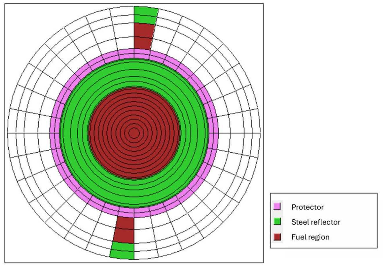
Figure 2.
Description of the calculation cycle for the simulation of an MSR, based on the HELIOS package.
Figure 2.
Description of the calculation cycle for the simulation of an MSR, based on the HELIOS package.
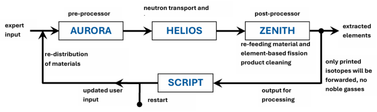
Figure 4.
System criticality over operational period for the demonstrator with the power set to 1MW, 10MW, and 50MW as reference system without feeding provided.
Figure 4.
System criticality over operational period for the demonstrator with the power set to 1MW, 10MW, and 50MW as reference system without feeding provided.
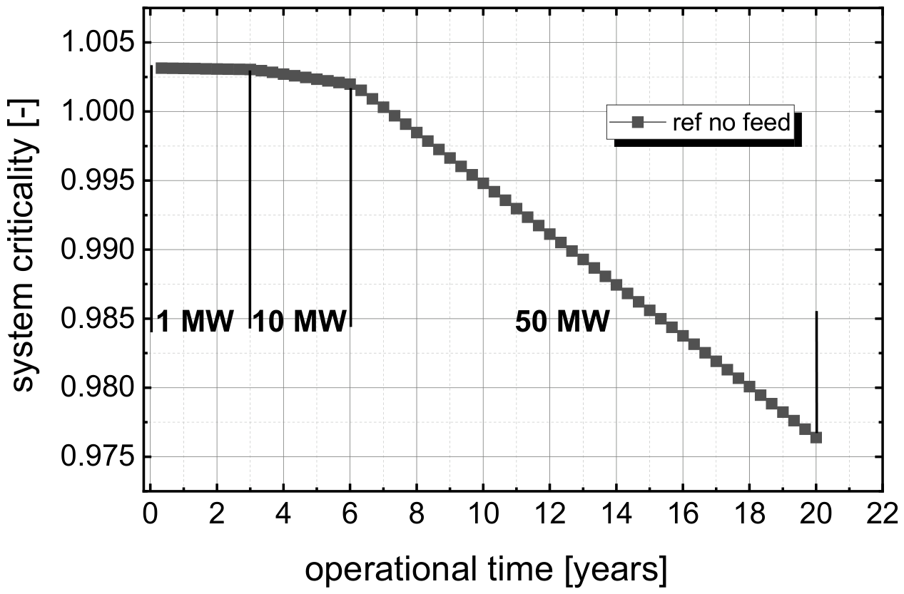
Figure 5.
Integrated heavy metal concentration over operational period for the different considered feeding strategies.
Figure 5.
Integrated heavy metal concentration over operational period for the different considered feeding strategies.
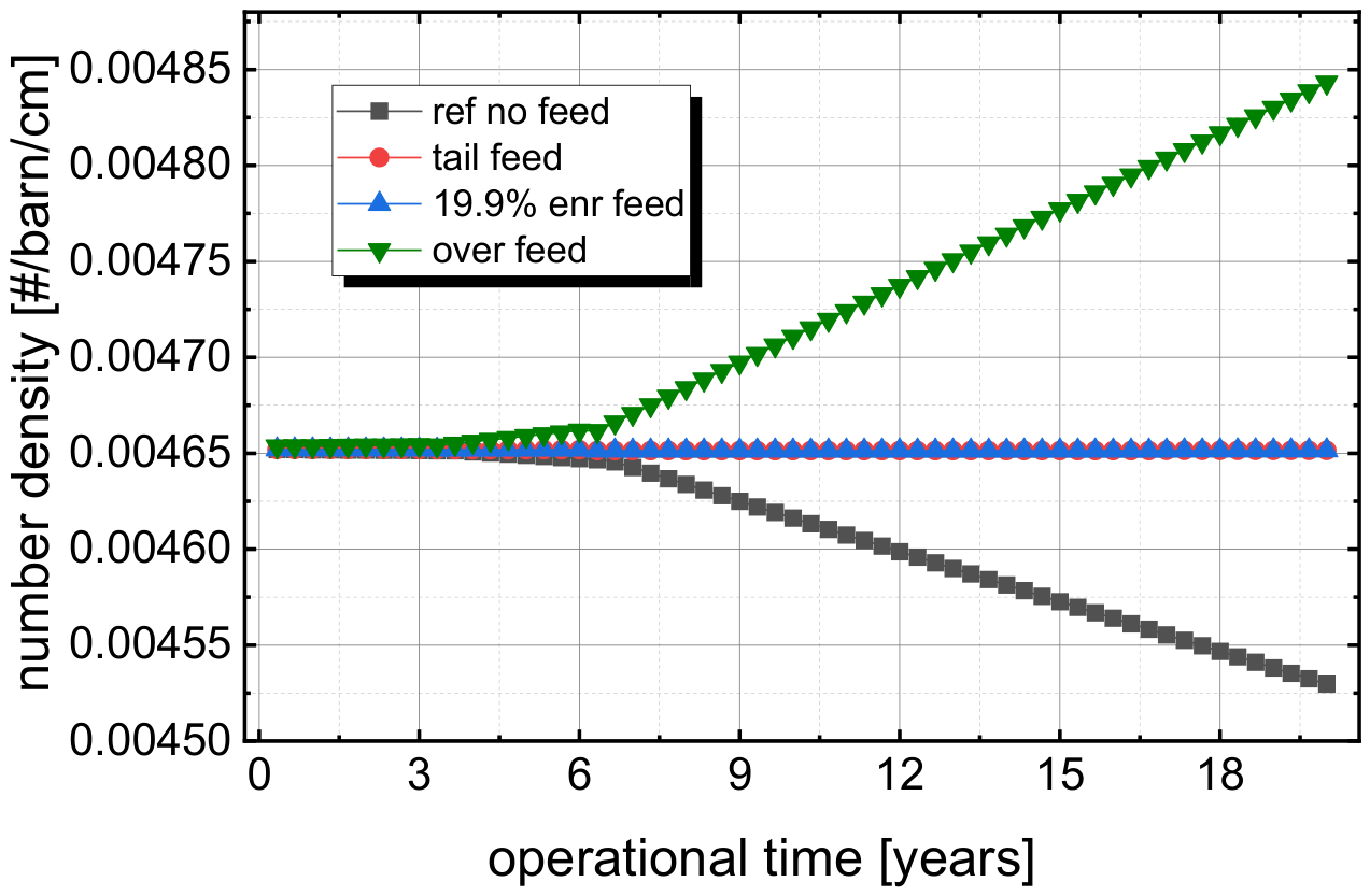
Figure 6.
Comparison of the system criticality over operational period for the different considered feeding strategies.
Figure 6.
Comparison of the system criticality over operational period for the different considered feeding strategies.
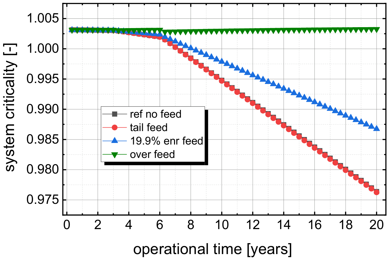
Figure 7.
Comparison of the concentration of the leading fissile materials for the different considered feeding strategies.
Figure 7.
Comparison of the concentration of the leading fissile materials for the different considered feeding strategies.
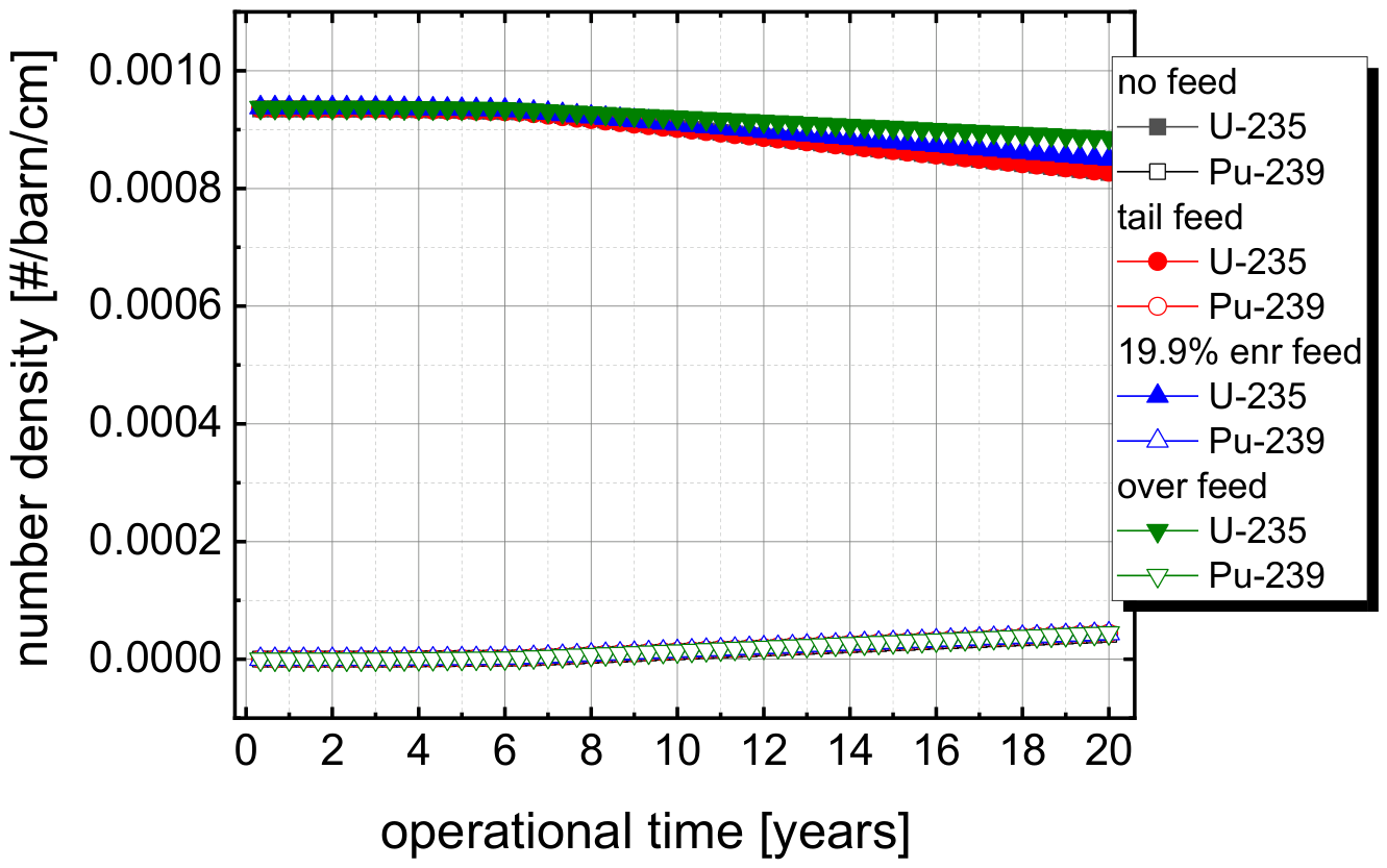
Figure 8.
System criticality versus operational time for the case with temperature and density adaption to compensate the criticality loss.
Figure 8.
System criticality versus operational time for the case with temperature and density adaption to compensate the criticality loss.
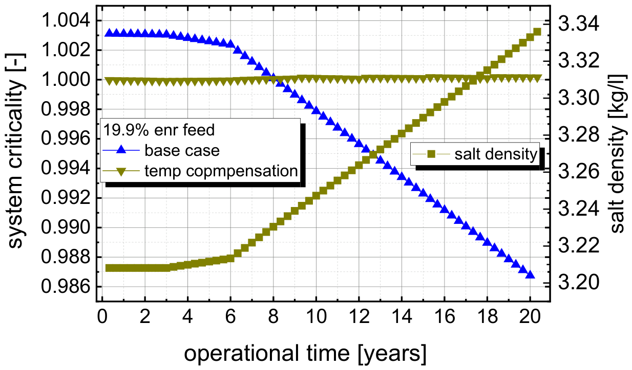
Figure 9.
Fission product concentration over operational time for the most relevant elements without and with clean-up fo three elements (Mo, Ru, and Pd).
Figure 9.
Fission product concentration over operational time for the most relevant elements without and with clean-up fo three elements (Mo, Ru, and Pd).
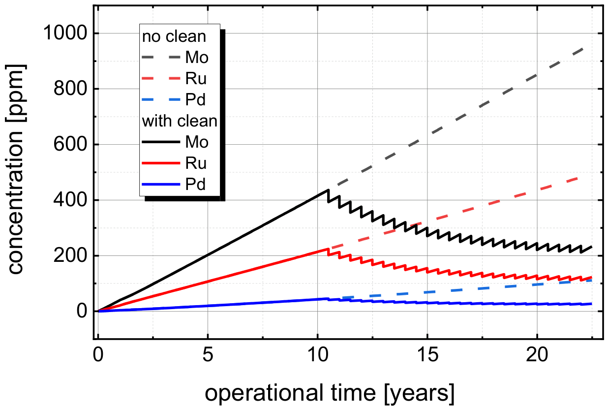
Figure 10.
System criticality versus operational time for the case with temperature and density adaptation to compensate the criticality loss, comparison for the system without and with salt clean-up.
Figure 10.
System criticality versus operational time for the case with temperature and density adaptation to compensate the criticality loss, comparison for the system without and with salt clean-up.
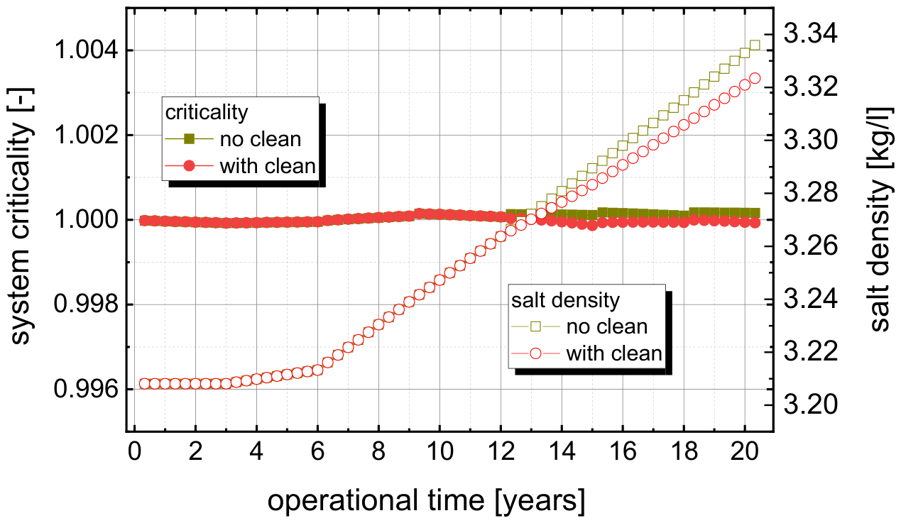
Figure 11.
Criticality over burnup curve for all 4 cases of the initial enrichment variation.
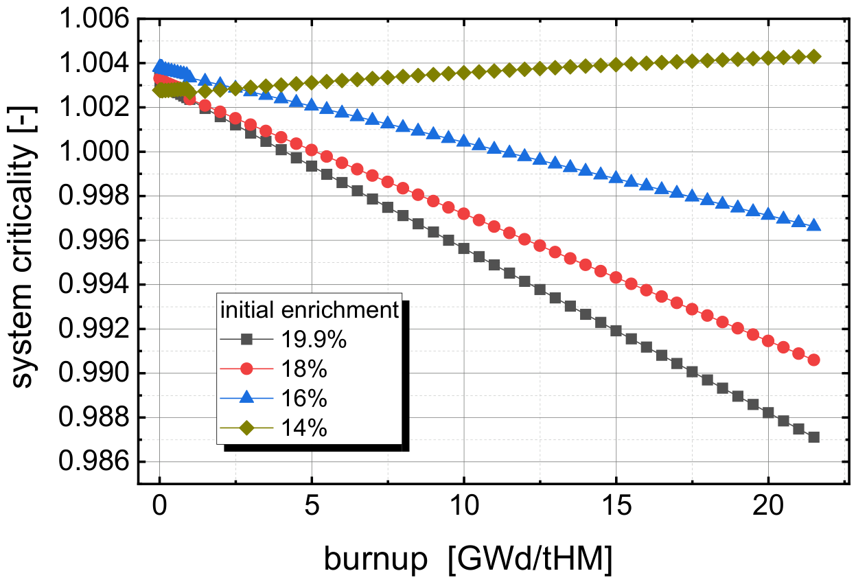
Figure 12.
Criticality over operational time curve for all 4 cases of the initial enrichment variation.
Figure 12.
Criticality over operational time curve for all 4 cases of the initial enrichment variation.
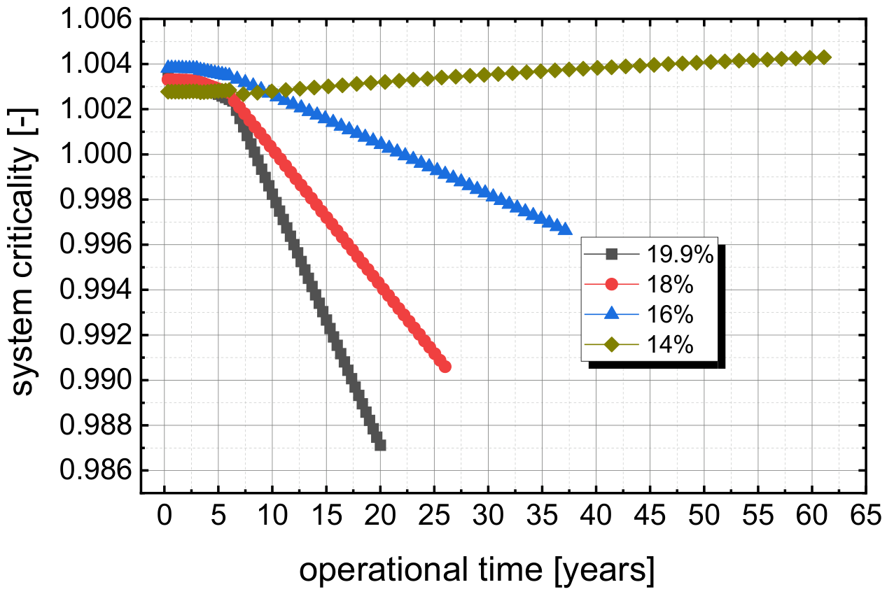
Figure 13.
Number densities of fissile materials over burnup for different core sizes.
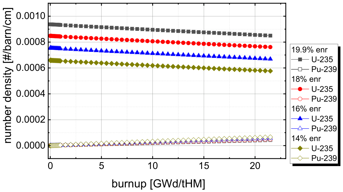
Figure 14.
Number densities of fissile materials over operational time for different core sizes.
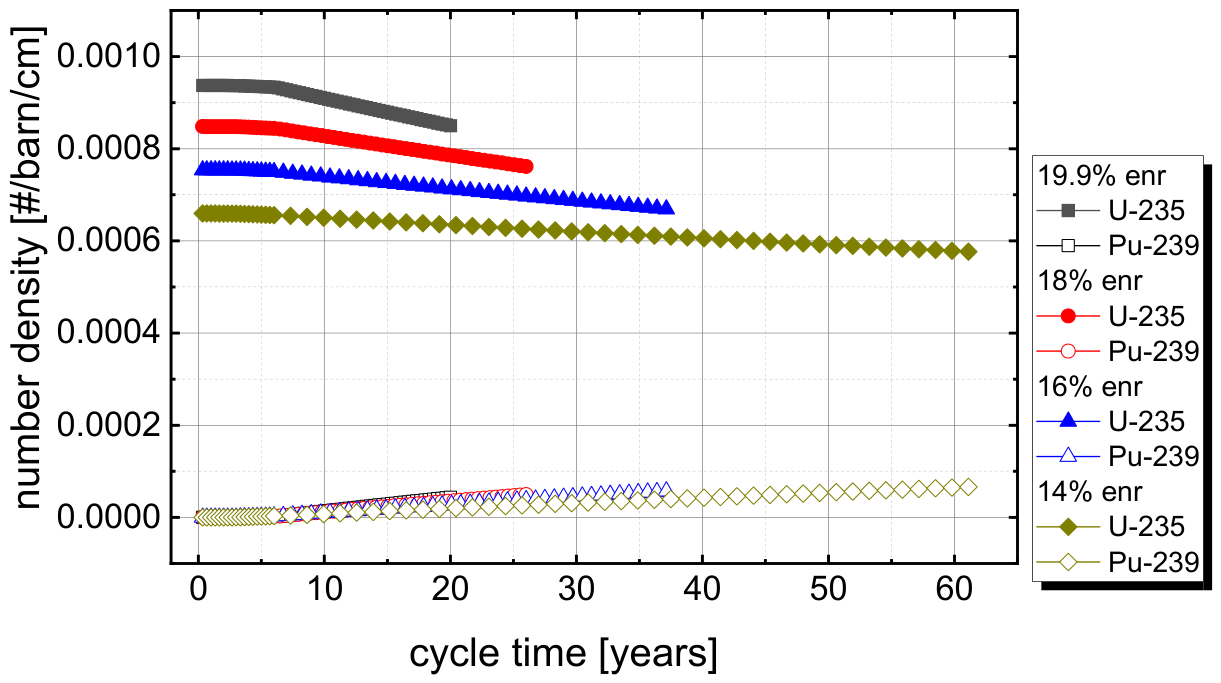

Table 1.
Detailed data on fuel temperature and density applied for the criticality correction.
| cycles | Fuel temperature [K] | Fuel density [kg/l] | Density multiplier used in HELIOS | Power [MW] |
| 1-9 | 1003 | 3.208123 | 1 | |
| 10-18 | 998 | 3.213251 | 1.000178 | 10 |
| 19-27 | 973 | 3.238891 | 1.000887 | 50 |
| 28-36 | 949 | 3.263506 | 1.000844 | 50 |
| 37-45 | 924 | 3.289146 | 1.000873 | 50 |
| 46-55 | 899 | 3.314786 | 1.000866 | 50 |
| 56-60 | 873 | 3.341451 | 1.000894 | 50 |
Table 2.
detailed data on fuel temperature and density applied for the criticality correction combined with fuel clean-up.
Table 2.
detailed data on fuel temperature and density applied for the criticality correction combined with fuel clean-up.
| cycles | Fuel temperature [K] | Fuel density [kg/l] | Density multiplier used in HELIOS | Power [MW] |
| 1-9 | 1003 | 3.208123 | 1 | |
| 10-18 | 998 | 3.213251 | 1.000178 | 10 |
| 19-27 | 973 | 3.238891 | 1.000887 | 50 |
| 28-36 | 949 | 3.263506 | 1.000844 | 50 |
| 37-45 | 930 | 3.282992 | 1.000663 | 50 |
| 46-55 | 908 | 3.305555 | 1.000764 | 50 |
| 56-60 | 886 | 3.328118 | 1.000758 | 50 |
Table 3.
Detailed data on reactivity loss between BOL and EOL and the enrichment of th efeed which would be required to keep the system close to criticality.
Table 3.
Detailed data on reactivity loss between BOL and EOL and the enrichment of th efeed which would be required to keep the system close to criticality.
| Initial U-235 enrichment [%] | Reactivity loss [pcm] at EOL | Feed enrichment [%] required to hold criticality |
| 19.9 | 1589 | 45% |
| 18 | 1272 | 37% |
| 16 | 736 | 29% |
| 14 | -153 | 19.5% |
Table 4.
Results for different initial enrichemnts and the correlated core sizes including estimated fuel costs.
Table 4.
Results for different initial enrichemnts and the correlated core sizes including estimated fuel costs.
| Initial U-235 enrichment [%] | Reactivity loss [pcm] at EOL |
Core Volume [m3] |
Fuel mass [t] | Heavy metal mass [t] |
Estimated Uranium cost [m$] |
| 19.9 | 1589 | 5.4 | 19.6 | 11.8 | 202 |
| 18 | 1272 | 7.7 | 28.0 | 16.8 | 259 |
| 16 | 736 | 12.0 | 43.6 | 26.1 | 357 |
| 14 | -153 | 21.2 | 77.1 | 46.3 | 551 |
Table 5.
Constant operational time and variable power to achieve the target burnup of 22 GWd/tHM.
| Initial U-235 enrichment [%] |
Core Volume [m3] |
max. System Power [MW] | Energy produced through lifetime [GWd] | Operational time [years] |
| 19.9 | 5.4 | 50 | 259 | 20 |
| 18 | 7.7 | 71 | 369 | 20 |
| 16 | 12.0 | 111 | 575 | 20 |
| 14 | 21.2 | 197 | 1018 | 20 |
Table 6.
Variable operational time and constant power to achieve the target burnup of 22 GWd/tHM.
| Initial U-235 enrichment [%] |
Core Volume [m3] |
max. System Power [MW] | Energy produced through lifetime [GWd] | Operational time [years] |
Reactivity loss after 20 years [pcm] |
| 19.9 | 5.4 | 50 | 259 | 20 | 1636 |
| 18 | 7.7 | 50 | 369 | 26 | 930 |
| 16 | 12.0 | 50 | 575 | 37 | 336 |
| 14 | 21.2 | 50 | 1018 | 61 | -42 |
Disclaimer/Publisher’s Note: The statements, opinions and data contained in all publications are solely those of the individual author(s) and contributor(s) and not of MDPI and/or the editor(s). MDPI and/or the editor(s) disclaim responsibility for any injury to people or property resulting from any ideas, methods, instructions or products referred to in the content. |
© 2026 by the authors. Licensee MDPI, Basel, Switzerland. This article is an open access article distributed under the terms and conditions of the Creative Commons Attribution (CC BY) license (http://creativecommons.org/licenses/by/4.0/).
Copyright: This open access article is published under a Creative Commons CC BY 4.0 license, which permit the free download, distribution, and reuse, provided that the author and preprint are cited in any reuse.