
Preprint
Article

This version is not peer-reviewed.

Understanding How Layer Ordering Effects the Electronic Stopping Power of Protons in Multi-Layered Carbon Materials

Submitted:

07 August 2026

Posted:

07 August 2026

You are already at the latest version

Abstract
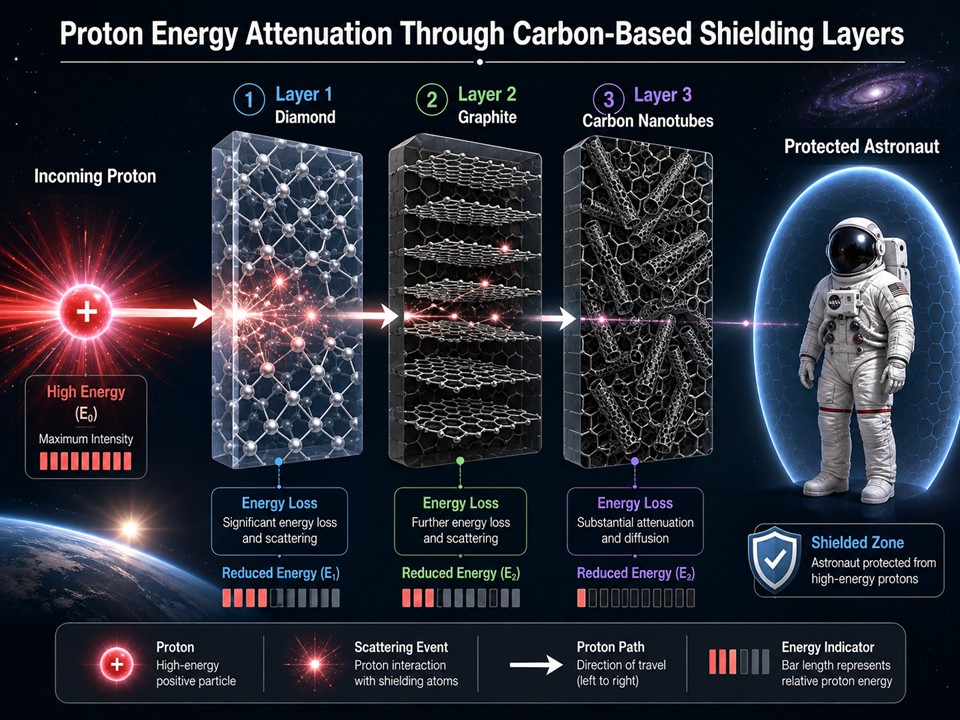
Space travel is hazardous because its environment contains higher amounts of radiation compared to the Earth. For this reason, materials must be optimized for radiation shielding to protect organic life forms and electrical equipment. This project focuses on creating effective shielding for protection against space radiation. The Stopping Range of Ions in Matter (SRIM) is a software used to simulate the electronic stopping power of protons in materials and can assist in optimizing them for shielding. SRIM was used to simulate diamond (D), graphite (G), carbon nanotubes (CNT) and combinations of material layer ordering consisting of the three allotropes with 145 MeV Protons. Results showed that diamond, graphite and carbon nanotube (D_G_CNT) were the optimal order of layering for minimum penetration depth amongst these multi-layered materials. The multi-layered material CNT_G_D having the least effective stopping power reordered to D_G_CNT, the travel depth reduces by 28.14%, showing how layer ordering effects the stopping power of a material.
Keywords: 
;  ;  ;  ;  ;  

1. Introduction

Space consists of a higher range of radiation levels compared to Earth, making it hazardous for both astronauts and electronics as they can accumulate radiation damage [1]. Space radiation consists mostly of protons and electrons that come from solar particle events (SPE), galactic cosmic radiation (GCR) [2] and solar cosmic rays (SCR). GCR contains around 85% protons and 12% alpha particles, and SCR contains around 90% protons and 9% electrons [3]. Shielding for space needs to be designed to protect organic life forms and electronic equipment. Furthermore, we are investigating materials which may be utilized for space shielding, with the goal of finding and optimizing the best materials for which multi-layered materials show promising results. Since space consists of a range of radiation types, the usage of single-layer structured shielding materials may not provide protection for other radiation types while being strong in one [3]. Multi-layered structured materials could approve the weaknesses of single-layer materials if the materials used in the multi-layer are optimized properly. Aluminum (Al) has been extensively experimented and simulated with other materials for multi-layered purposes [1,2,3,4,5]. Using the On-line Tool for the Assessment of Radiation in Space (OLTARIS), a single layer of Al used for radiation versus using a multi-layer of Al and other various materials; the latter has a lower dose equivalent compared to the former, with Al + lithium hydride (LiH) having the lowest dose equivalent, overall, providing better radiation shielding [1]. For proton shielding, multi-layer materials are effective for shielding where Al bronze-molybdenum-Al bronze shields proton at an improved level compared to single layer pure Al [3]. Nanocomposites is another form of multi-layering and [4] shown an Al-CNT composite reduces radiation damage by one order of magnitude compared to pristine Al and enhances the recombination of defects produced by irradiation created higher tolerance. Henceforth, multi-layered materials show radiation shielding capabilities superior to those of single-layered materials. Finding the most optimize layering a problem in investigation.
An issue with radiation shielding is the materials used to produce it. Although Al has a relatively high mechanical strength, compared to other materials of space radiation, the proton shielding capabilities on their own are relatively weak [3]. Al due to its charge-to-mass ratio also has higher probability to fragment from incoming radiation, producing secondary particles which can induce more internal damage in the shield [5]. A common solution to this problem is using polymers containing low Z-atoms like hydrogen (H) and carbon (C). Low Z-atoms due to their higher quantity of free electrons are more effective at reducing the energies of the incident protons than that of high Z-atoms and don’t produce the number of secondary particles compared to high Z-atoms [3]. Polymers like polyethylene layered with Al have shown even reduced the proton radiation dose [6]. While polymers do consist of low Z-atoms, their structural and thermo properties fall short to materials like Al. Many studies have been done to further investigate improvements in these weaknesses using carbon nanotubes (CNT) [7,8,9,10].
Carbon structures such as graphite (G) [11], diamond (D) [12] and CNT have been investigated as well. Nano-diamonds and CNT exhibit high mechanical and chemical strength high temperature of degradation, ultraviolet protection and EM absorbing properties [13]. Onion like Carbon (OLC) structures have also shown unique conducting/magnetic/lubrication/EM absorbing properties [13]. We investigate carbon-based multi-layered materials as carbon is a low Z-atom, offering lightweight structural enhancement in materials.

2. Methods

We approach the project using a software called “Stopping Range of Ion in Materials” (SRIM) [14,15] where calculations were performed on various carbon materials [16]. SRIM simulates ion radiation, as space radiation consists mostly of protons making SRIM a valuable tool in simulating space shielding. This work studies material layouts that are best optimized for proton radiation shielding using carbon allotropes. SRIM is a Monte Carlo simulation [8,12] used to calculate the electronic stopping power of materials. It is based on the Bethe-Bloch equation [17], where it is the derivative of the loss of energy over the material width traveled ( d E d x ). SRIM is ion focused, where the radiation type is the charge and mass of the particle. SRIM does not take crystal structure into account, as it treats them as amorphous [18]. SRIM does consider the density of the material effecting its stopping power and this is also what we are looking into as well. SRIM has been shown to agree with experimentation [16] and provides high accuracy with an ion count between 10,000 - 20,000 yielding less than 1% statistical uncertainty for ion-solid interactions [18]. The carbon allotropes are diamond (D) with a density of 3.54 g/cm3 [19], graphite (G) with a density of 2.26 g/cm3 [19], and carbon nanotube (CNT) with a density of 1.74 g/cm3 [20]. Two separate types of simulations were done; ionization + recoiling and incident ion depth distribution. For both simulations, the full cascade calculation was used so all ion-solid interactions were accounted for. The output file IONIZ.txt produced by SRIM was used for ionization and recoil analysis.

2.1. Ionization and Recoils

The first simulation type consists of six materials with each varying a different layer order of the three carbon allotropes. The width of the materials is 76.1 mm with each layer being a third of that. The reason for this width has to do with the ion travel depth not exceeding the materials’ width while also covering most of it. The SRIM results show how the ionization and recoiling through the material changes when the layering order differentiates. Ionization is the amount of an incident ion’s energy deposited per distance in the material through electronic interaction. The electrons of the atoms in the material structure interact with the incident ion creating an inelastic collision, which results in energy deposited in the material and the ion slowing down. Recoiling is the amount of energy deposited in the material through nuclear interaction by the incident ion and the material structure’s atoms. That resulting atom in the structure is the recoil, produced by the ion. The nucleus of the incident ion collides with the nuclei of the material structure which can cause the atoms to either displace and produce a Frenkel pair (a vacancy and interstitial detect) in the structure, produce secondary recoil atoms which are produced by initial recoils, or return to initial position and produce a phonon. The incident ion energy parameter used was 145 MeV hydrogen ion with an ion count of 10,000.

2.2. Incident Ion Depth Distribution

The second simulation type includes the carbon allotropes individually and the multi-layered materials, 145 MeV proton, and an ion count of 10,000. The major change is width of the materials (100 mm). The purpose of this simulation is to see the stopping power of the different materials and how varying the order of the allotropes influences it. We also look at the straggling effect of the ion in the materials which can be considered the standard deviation of the ions from the mean travel depth.

3. Results and Discussion

3.1. Ionization and Recoil Data

The results of the first simulation shown in Figure 1 (a-f) and Figure 2 (a-f) display the ionization and recoiling energies of the six sets of carbon materials with the varying allotrope orders.
In Figure 1, panel a through f consists of different carbon allotrope layering. Depending on how the allotropes are layered will change the ionization effects of the material. There is more ionization in the more dense layers of the materials compared to the less dense layers. When the ion travels through the material, it decreases in velocity, depositing more energy per distance traveled as shown in each panel. This is especially shown when the ion slows almost to a complete stop, the ionization grows exponentially creating a peak. This phenomenon is called Bragg’s peak, which indicates the ion has stopped relative to that depth of the material and deposits all its remaining energy in that final depth. The Bragg’s peak is the highest in panel d and f in their third layers compared to the others in Figure 1. The first two layers of each material (G_CNT and CNT_G) do not absorb as much energy leading D, being denser, absorbing most of it. The reason has to do with the speed of the ion to where G and CNT slow down the ion enough for the diamond layer to absorb it all, as to why D in panel a, b, c, e does not absorb as much if it is not last in the three-layer combination. For materials like Figure 1, panels a and c, the ionization in each layer is slightly closer in rate to each other in the layers’ respected material, compared to the major change in panels d and f, and even panels b and e. The Bragg’s peak in panels a and c is the lowest in Figure 1, as energy is deposited more in the initial layers. This has to do with the higher density in both D and G as the incident ion has more to interact with in the layer initially. Therefore, more ionization happens in the beginning, leading to a lower Bragg’s peak. The application of this principle can be useful if a particular layer is preferred for ionization or if the speed of an ion needs to be reduced significantly throughout the shield.
In Figure 1, panels a and c, panels b and e, and panels d and f respectively share similar ionization effects at the end of the material depth as they share the same carbon allotrope in the third layer respectively. The differences between the respected pairs are the changes in the amount of ionization which is affected by the layer’s allotrope that is first followed by the other. Panels a, b, and d have more ionization in their first layer due to them beginning with a denser allotrope in contrast with their middle layer. Panels c, e, f has more ionization in their second layer due to the materials having a denser allotrope as the middle layer is constant with their first layer. Relating to the first two allotrope layers, the ionization tends to be closer in ionization rate when the denser allotrope begins the material, followed by the less dense one. When that is reversed, there is a difference in ionization has the middle layer absorbs significantly more than the first. However, the order of the first two layers in the material does not significantly affect the ionization depth in the third layers of the respected materials.
In Figure 2, panels a to f, like Figure 1, also show the different layering orders, but looking at energy lost through ion-nuclear interactions that produce recoils. The higher the energy lost, the more drastic the collision is. On average, denser allotropes like D generate more recoils and have the most drastic collisions as it contains more atoms for the incident ion to interact with. This only starts to change as the ion travels through the materials, and the recoils start to increase more. An explanation for this is that the more the incident ion decreases in velocity, the interaction of the ion with the materials’ structures increase. This also explains why recoils grow exponentially in the last layers of the materials respectively, like Figure 1 (a-f) on the behavior of ionization. The energy lost in recoils is significantly lower than the energy lost in ionization with SRIM displaying 99.97% energy lost in ionization and 0.03% energy lost in recoils. The incident ion being hydrogen (H), which is a low-Z atom will vastly lose more energy in ionization due to both its size and charge. Since it is much lighter compared to the carbon atoms, not much energy is exchanged between the nuclear interactions, but more is exchanged through ion-electron interaction as H is very ionic and small, allowing for the electrons to interact with the ion easier.
Depending on how the material is layered can affect the shielding capabilities of that material, with density being no acceptation. The materials having the same type of carbon allotropes with different densities, just by varying the layers changed the ionization and recoiling properties. D_G_CNT compared to the others shown to have the shortest penetration depth and relatively equaled ionization through its layers.

3.2. Incident Ion Depth Distribution Data

Table 1 displays the incident ion depth distribution data with column 1 containing the materials that were simulated. Column 2 contains the mean travel depth ranging from the most distance traveled to the least. The travel distance is an inverse of the stopping power of the material, where D has the greatest. Column 3 displays the straggling of these materials with respect to the incident ion, where is the lowest in D. Column 4 is the percentage difference (Δ%) that represents the change in travel depth following the former material to the next doing down the table. Column 5 represents the overall change in travel depth in respect to the width of the material (100 mm).
The difference of depth penetration for single allotrope materials, CNT to G has a reduction of 23.03% with a 29.89% increase in density. G to D has a larger reduction of 36.20% with a 56.64% increase in density. CNT to D has the largest reduction of 50.89% with a 103.45% increase in density. Increasing the density of the material does affect the stopping power, but it is not a one-to-one ratio. As the density of the material increases, the stopping power increases logarithmically. In other words, the rate of increase for stopping power decreases as the density of the material increases.
What is interesting is the behavior of the multi-layer materials where the stopping power changes depending on the order of the allotropes. CNT_G_D has the most travel depth of 75.7 mm among the multi-layered materials reduces to 54.4 mm when re-ordered to the least depth penetration multi-layer material D_G_CNT, a 28.14% reduction. What also changes are the straggling behavior which there is a 35.49% increase from 0.710 to 0.962. The explanation has to do with the positioning of the layers and where the incident ions stop in. In CNT_G_D, the ions stop in layer D where it has shown to have the lowest straggling. In D_G_CNT, the ions stop in layer G which G has the highest straggling amongst the single allotrope materials. This shows how density and the order of it affects the stopping of a material and how the ions are distributed.

4. Conclusions

The simulations done by SRIM show promising results of the material layering as D_G_CNT has the greatest stopping power compared to the other multi-layering shielding materials. According to SRIM D_G_CNT were the optimal order of layering for minimum penetration depth into these multi-layered materials. The multi-layered material CNT_G_D having the least effective stopping power when re-order to D_G_CNT, the travel depth reduces by 28.14%. However, CNT_G_D could be utilized if the goal for a multi-layered material is to use certain layers for the purpose of depositing ions in a designated layer. This shows how layer order affects the stopping power of a material as indicated with an increase in stopping power and the potential utility in other applications not just solely in raw stopping power.
In contrast, limitations to SRIM do not allow us to fully explore all the capabilities of these materials as it only simulates ion-based radiation and treats the material’s crystal structure as amorphous. It does assist in guiding experimental parameters to result in safer radiation shielding materials, i.e., what we should expect when we run experiments on certain materials. SRIM can be used to optimize and engineer materials for shielding protons for space application.

Author Contributions

Conceptualization, C.W..; methodology, C.W.; software, C. W., T.D., validation, M.P. ;formal analysis, C.W.; investigation, M.P.; resources, M.P.; data curation, C.W.; writing—original draft preparation, M.P. and C.W..; writing—review and editing, M.P..; visualization, M.P..; supervision, M.P..; project administration, M.P..; funding acquisition, M.P. Simulation: C.W.

Funding

This project was supported by Department of Energy MSIPP Gulf Coast A&M Consortium: Materials-At-The-Extreme (MATE) - Material Science for Extreme Environments.

Data Availability Statement

the data is available upon request, mepulikkathara@pvamu.edu.

Conflicts of Interest

The authors declare no conflicts of interest. The funders had no role in the design of the study; in the collection, analyses, or interpretation of data; in the writing of the manuscript; or in the decision to publish the results.

Acknowledgments

This research study is deeply indebted to the recently passed Professor Richard Wilkins of Electrical Engineering at Prairie View A&M University for his mentoring and all his support. We are grateful for Dr. Matthew Wadsworth of Florida A&M University for helping to edit and discuss this manuscript.

References

  1. Gohel, A.; Makwana, R. Multi-layered shielding materials for high energy space radiation. Radiat. Phys. Chem. 2022, 197. [Google Scholar] [CrossRef]
  2. Thibeault, S. A.; Kang, J. H.; Sauti, G.; Park, C.; Fay, C. C.; King, G. C. Nanomaterials for radiation shielding. In MRS Bulletin; Materials Research Society, 2015; Vol. 40, Issue 10, pp. 836–841. [Google Scholar] [CrossRef]
  3. Wang, M.; Wang, Q.; Xiao, Y.; Wang, M.; Wang, J.; Wang, H.; Chen, Z. Review of Passive Shielding Materials for High-Energy Charged Particles in Earth’s Orbit. In Materials; Multidisciplinary Digital Publishing Institute (MDPI), 2025; Vol. 18, Issue 11. [Google Scholar] [CrossRef] [PubMed]
  4. Cao, P.; So, K. P.; Yang, Y.; Park, J. G.; Li, M.; Yan, L.; Hu, J.; Kirk, M.; Li, M.; Lee, Y. H.; Short, M. P.; Li, J. Carbon nanotube (CNT) metal composites exhibit greatly reduced radiation damage. Acta Mater. 2021, 203. [Google Scholar] [CrossRef]
  5. Li, Z.; Chen, S.; Nambiar, S.; Sun, Y.; Zhang, M.; Zheng, W.; Yeow, J. T. W. PMMA/MWCNT nanocomposite for proton radiation shielding applications. Nanotechnology 2016, 27(23), 234001. [Google Scholar] [CrossRef] [PubMed]
  6. al Zaman, M. A.; Roy, S.; Sarker, S.; Azad, M. M. U.; Akib, A. A.; Haque, M. M. Comparative analysis of the effectiveness of natural polymers and conventional space radiation shielding polymers in spacecraft for prolonged space expeditions. Mater. Res. Express 2023, 10(11), 115301. [Google Scholar] [CrossRef]
  7. Li, Z.; Nambiar, S.; Zheng, W.; Yeow, J. T. W. PDMS/single-walled carbon nanotube composite for proton radiation shielding in space applications. Mater. Lett. 2013, 108, 79–83. [Google Scholar] [CrossRef]
  8. Zaccardi, F.; Toto, E.; Rastogi, S.; la Saponara, V.; Santonicola, M. G.; Laurenzi, S. Impact of Proton Irradiation on Medium Density Polyethylene/Carbon Nanocomposites for Space Shielding Applications. Nanomaterials 2023, 13(7). [Google Scholar] [CrossRef] [PubMed]
  9. Inglefield, D. L.; Bodnar, R. J.; Long, T. E. Hydrogen bond containing multiwalled carbon nanotubes in polyurethane composites. Polym. Compos. 2016, 37(5), 1425–1434. [Google Scholar] [CrossRef]
  10. Fourie, L. F.; Square, L.; Arendse, C.; Msimanga, M. ABPBI/MWCNT for proton radiation shielding in low earth orbit. APL Mater. 2023, 11(7). [Google Scholar] [CrossRef]
  11. Amirkhani, M. A.; Asadi Asadabad, M.; Hassanzadeh, M.; Mirvakili, S. M. The effects induced by proton irradiation on structural characteristics of nuclear graphite. J. Radioanal. Nucl. Chem. 2019, 321(2), 701–709. [Google Scholar] [CrossRef]
  12. Crnjac, A.; Jakšić, M.; Matijević, M.; Rodriguez-Ramos, M.; Pomorski, M.; Siketić, Z. Energy loss of MeV protons in diamond: Stopping power and mean ionization energy. Diam. Relat. Mater. 2023, 132. [Google Scholar] [CrossRef]
  13. Shenderova, O.; Jones, C.; Borjanovic, V.; Hens, S.; Cunningham, G.; Moseenkov, S.; Kuznetsov, V.; McGuire, G. Detonation nanodiamond and onion-like carbon: applications in composites. Phys. Status Solidi (a) 2008, 205(9), 2245–2251. [Google Scholar] [CrossRef]
  14. Ziegler, J. F. SRIM—The Stopping and Range of Ions in Matter. 2013. Available online: http://www.srim.org/.
  15. Ziegler, J. F.; Ziegler, M. D.; Biersack, J. P. SRIM - The stopping and range of ions in matter (2010). Nuclear Instruments and Methods in Physics Research, Section B: Beam Interactions with Materials and Atoms 2010, 268(11–12), 1818–1823. [Google Scholar] [CrossRef]
  16. Evseev, I. G.; Schelin, H. R.; Paschuk, S. A.; Milhoretto, E.; Setti, J. A. P.; Yevseyeva, O.; de Assis, J. T.; Hormaza, J. M.; Díaz, K. S.; Lopes, R. T. Comparison of SRIM, MCNPX and GEANT simulations with experimental data for thick Al absorbers. Appl. Radiat. Isot. 2010, 68(4–5), 948–950. [Google Scholar] [CrossRef] [PubMed]
  17. Ziegler, J. F.; Biersack, J. P.; Ziegler, M. D. Chapter 4 - Stopping of Energetic Light Ions. In SRIM - the Stopping and Range of Ions in Matter; 2015; Volume 4, pp. 1–48. ISBN 0-9654207-1-X. [Google Scholar]
  18. Ali, Z.; Liu, F.; Wang, Y.; Rasool, H. G.; Wang, F.; Haseeb, M. Advancements in primary radiation damage models and SRIM simulations: A review of radiation damage predictions. In Nuclear Engineering and Technology; Korean Nuclear Society, 2025; Vol. 57, Issue 8. [Google Scholar] [CrossRef]
  19. Hossain, M. D.; Zhang, Q.; Cheng, T.; Goddard, W. A.; Luo, Z. Graphitization of low-density amorphous carbon for electrocatalysis electrodes from ReaxFF reactive dynamics. Carbon 2021, 183, 940–947. [Google Scholar] [CrossRef]
  20. Kim, S. H.; Mulholland, G. W.; Zachariah, M. R. Density measurement of size selected multiwalled carbon nanotubes by mobility-mass characterization. Carbon 2009, 47(5), 1297–1302. [Google Scholar] [CrossRef]
Figure 1. Ionization of hydrogen (145 MeV) in carbon materials from the IONIZ.txt file. Panels a-f illustrate the energy lost in ionization per distance traveled. Panel a represents the layering order D_G_CNT. Panel b represents the layering order D_CNT_G. Panel c represents the layering order G_D_CNT. Panel d represents the layering order G_CNT_D. Panel e represents the layering order CNT_D_G. Panel f represents the layering order CNT_G_D.
Preprints 227269 g001
Figure 2. Recoil of hydrogen (145 MeV) in carbon materials from the IONIZ.txt file. Panels a-f illustrate energy lost in recoils per distance traveled. Panel a represents the layering order D_G_CNT. Panel b represents the layering order D_CNT_G. Panel c represents the layering order G_D_CNT. Panel d represents the layering order G_CNT_D. Panel e represents the layering order CNT_D_G. Panel f represents the layering order CNT_G_D.
Preprints 227269 g002
Table 1. Displays the depth penetration of the ions in the materials. Column 1 is the respective materials, column 2 is the average depth traveled for the 145 MeV proton in the material, column 3 is the deviation, or straggle, of the ion distribution from the average depth value, column 4 is the percentage change (∆%) decrease in depth following the previous material and column 5 is the ∆% decrease from the overall material depth.
Material (100 mm) Mean Depth (mm) Straggling (mm) Δ% Decrease Δ% Decrease from 100 mm
CNT 95.1 1.130 0 4.90
CNT_G_D 75.7 0.710 20.40 24.30
G_CNT_D 75.7 0.644 0 24.30
G 73.2 1.180 3.30 26.80
CNT_D_G 63.7 0.654 12.98 36.30
D_CNT_G 60.7 1.190 4.71 39.30
G_D_CNT 58.8 0.621 3.13 41.20
D_G_CNT 54.4 0.962 7.48 45.60
D 46.7 0.548 14.15 53.30
Disclaimer/Publisher’s Note: The statements, opinions and data contained in all publications are solely those of the individual author(s) and contributor(s) and not of MDPI and/or the editor(s). MDPI and/or the editor(s) disclaim responsibility for any injury to people or property resulting from any ideas, methods, instructions or products referred to in the content.
Copyright: This open access article is published under a Creative Commons CC BY 4.0 license, which permit the free download, distribution, and reuse, provided that the author and preprint are cited in any reuse.