

Submitted:
03 August 2026
Posted:
04 August 2026
You are already at the latest version
Abstract
Adaptive cruise control (ACC) and related advanced driver assistance systems (ADAS) regulate vehicle speed mainly for safety and comfort. In a battery electric vehicle (BEV), the same speed decisions also determine energy use, and therefore range. This concept paper couples the two concerns: a predictive longitudinal controller is developed, from first principles and without empirical validation, that plans ADAS speed and manages BEV energy within a single problem. The vehicle longitudinal dynamics, the powertrain efficiency map, and the regenerative brake-blending limits are embedded in a model predictive control (MPC) formulation whose cost function weighs gap-keeping safety, ride comfort, and battery energy over a receding horizon, informed by electronic-horizon (map and traffic) preview. To make the controller deployable, the safety-critical deceleration path is separated from the energy-optimization layer; this separation is supported by a worked hazard analysis (HARA) and by the derived ISO 26262 safety goals. A first-principles calculation shows that keeping a deceleration within the regeneration power limit recovers substantially more energy than late, hard braking. No simulation or vehicle data are reported: the contributions are the formulation, the safety architecture, and a concrete evaluation protocol, with its main threats to validity, to guide the quantitative study that should follow.
Keywords:
battery electric vehicle
; adaptive cruise control
; model predictive control
; regenerative braking
; eco-driving
; electronic horizon
; energy management
; ADAS
; functional safety
; energy-aware control
1. Introduction
The driving range of a battery electric vehicle is a leading factor in adoption, and it depends not only on battery capacity and powertrain efficiency but also on how the vehicle is driven. An increasing share of that driving is no longer controlled by the human driver: adaptive cruise control, traffic-jam assist, and higher levels of automation command traction and braking torque for large portions of real-world driving. This presents both a problem and an opportunity. The problem is that conventional ADAS longitudinal controllers are tuned for gap-keeping accuracy and occupant comfort, and the energy consequences of their acceleration and braking are treated as incidental; recent field evidence indicates that engaging ACC in a BEV can even increase energy use relative to a human driver under some conditions, partly because automation does not recover as much energy through regenerative braking [1]. The opportunity is that a controller which already commands the powertrain, and which can be given information about the road ahead, is well placed to shape the speed trajectory for low energy consumption to a degree a human driver cannot match [2].
This opportunity is larger in a BEV because of regenerative braking. In a conventional vehicle, every deceleration dissipates kinetic energy as heat; a BEV recovers part of it, but only within the torque, power, and state-of-charge limits of the electric drive and battery, and only for the portion of the braking served by the electric machine rather than the friction brakes. An ADAS controller that plans decelerations without regard to these limits routinely wastes recoverable energy, for example by braking late and hard where the regeneration power limit saturates, when an earlier and gentler deceleration would have recovered considerably more. Section 5.1 quantifies this effect from first principles.
The coupling between the two domains is addressed directly. Rather than treating eco-driving guidance and ADAS control as separate features, as is common in production vehicles, a single receding-horizon optimal control problem is formulated in which the ADAS objectives (safe gap regulation, speed-limit adherence, and comfort) and the BEV energy objective (minimum net battery energy over the horizon) are combined, subject to the physical constraints of the electrified powertrain, including the regenerative/friction brake-blending envelope. Preview information is supplied by an electronic horizon built from map attributes (grade, curvature, and speed limits) and, where available, traffic and infrastructure data.
The work is presented as a concept paper: it establishes a formulation and a deployment-oriented safety architecture, and specifies how they should be evaluated, but it reports no simulation or vehicle results. Its contributions are threefold. First, the coupled problem is formulated, comprising a control-oriented longitudinal energy model of the BEV with an explicit regeneration blending constraint (Section 3) and the receding-horizon cost that co-optimizes the ADAS and energy objectives (Section 4). Second, a systems-engineering decomposition of the resulting controller is proposed that separates the safety-relevant deceleration authority from the energy-optimization layer, and the ISO 26262 ASIL implications are made concrete through a hazard analysis with derived safety goals (Section 4.3). Third, in place of an empirical study, a first-principles analysis of the regeneration-envelope mechanism is given, together with a detailed and reproducible evaluation methodology (platform, drive cycles, baselines, metrics, and sensitivity analyses) that a subsequent quantitative paper can carry out (Section 5). Section 2 reviews related work; Section 6 discusses OEM integration and limitations; and Section 7 concludes.
2. Related Work
2.1. Eco-Driving and Predictive Speed Optimization
Eco-driving for electrified vehicles has been studied extensively as an optimal control problem, usually minimizing energy consumption over a known route with dynamic programming, Pontryagin’s minimum principle (PMP), or model predictive control. Representative BEV and electric-truck formulations combine topography and traffic preview with receding-horizon optimization and report energy reductions that depend strongly on the drive cycle and on traffic realism [3,4]. Hybrid learning/MPC schemes extend these methods to car-following and road-grade scenarios [5,6]. A recent real-world study using a PMP-based advisory system reported route-dependent savings and quantified how modeling simplifications and driver behavior erode the theoretical optimum [7]. Multi-objective and platoon formulations broaden the objective set to include mobility and safety alongside energy [8]. A recurring limitation is that many of these works treat the vehicle as free-flowing and do not model the interaction with a lead vehicle or the constraints of a production ADAS feature.
2.2. Energy-Aware Adaptive Cruise Control
A more targeted body of work adds energy terms to ACC, often termed Eco-ACC or predictive ACC. Nonlinear-MPC ecological ACC was demonstrated early for plug-in hybrids [9] and later specialized to electric powertrains with explicit energy-management objectives [10,11]. Published approaches differ in where the energy term enters (cost function or reference generation), in the predictor used for lead-vehicle motion [12,13], and in whether the controller respects production comfort constraints. Several report experimental or test-track validation of the energy benefit over a production-tuned ACC baseline [14,15], and robust-MPC variants address model mismatch [16]. A recent systematic review confirms that MPC remains the dominant technique for Eco-ACC, with reinforcement-learning and hybrid MPC–learning methods growing, and identifies battery-awareness and the simulation-to-reality gap as open problems [2]. What remains under-addressed, and what this paper targets, is the joint treatment of regenerative blending limits as hard constraints, the use of electronic-horizon preview in the same formulation, and the functional-safety decomposition needed to deploy such a controller in a production E/E architecture.
2.3. Regenerative Braking Control and Brake Blending
Regenerative braking and brake-blending control have been treated largely within the chassis and powertrain communities. Comprehensive reviews catalogue series and parallel blending topologies and the efficiency limits set by machine torque, speed, and battery charge acceptance [17]. Other work addresses blending under safety-critical and anti-lock conditions [18], multi-objective allocation that also manages brake thermal state and battery stress [19], and hierarchical hydraulic/regenerative coordination that ensures a smooth transition to friction braking at low speed [20]. These works generally take the deceleration request as given, whereas the ADAS literature generally treats the brake system as an ideal deceleration actuator. The interface between the two, namely how an ADAS deceleration request should be shaped so that the blending controller can serve it regeneratively, is the coupling exploited in this work.
2.4. Positioning of This Work
Relative to the above, the present framework is distinguished by three features: a single co-optimized formulation spanning the ADAS objectives and BEV energy, with regeneration limits as first-class constraints; an explicit safety decomposition intended for ISO 26262-conformant productization rather than simulation-only study; and a systems-integration perspective covering the E/E signal interfaces required in modern zonal and centralized architectures. Consistent with its status as a concept paper, the work contributes the formulation and the architecture and specifies their evaluation, leaving the quantitative comparison to subsequent study.
3. Control-Oriented Vehicle and Powertrain Model
3.1. Longitudinal Dynamics
The tractive force required at the wheels follows from the longitudinal force balance:
Ftrac = m·a + m·g·Cr·cos θ + ½ ρ·Cd·A·v2 + m·g·sin θ
Here m is the effective vehicle mass including rotational inertia, a the longitudinal acceleration, C_r the rolling-resistance coefficient, θ the road grade taken from the electronic horizon, ρ the air density, C_d the drag coefficient, A the frontal area, and v the vehicle speed. Grade preview is the most valuable electronic-horizon attribute for energy optimization, because the exchange of potential energy dominates the recoverable-energy budget on non-flat routes.
3.2. Powertrain Power Flow and Regeneration
The net electrical power drawn from (or returned to) the battery is modeled as:
Pbatt = Ftrac·v / ηdrv(Tm, ω), for Ftrac ≥ 0
Pbatt = − ηrgn(Tm, ω)·Frgn·v, for Ftrac < 0
Here η_drv and η_rgn are the combined inverter–machine–gearbox efficiency maps in traction and regeneration, expressed as functions of machine torque T_m and speed ω, and F_rgn is the portion of the braking force served by the electric machine. For a control-oriented implementation, the efficiency maps can be represented in several ways: as a two-dimensional lookup table with bilinear interpolation over measured or datasheet efficiency data; as a low-order quadratic power-loss fit that keeps the optimization smooth and differentiable; or through an established parametric battery/drive model such as that of Tremblay and Dessaint [21]. The choice trades fidelity against solver tractability. The framework is agnostic to it, and requires only that the map be evaluable and, ideally, convex or piecewise-smooth over the operating region, so that the receding-horizon problem of Section 4 remains solvable in real time.
3.3. Brake Blending Constraint
The total braking force splits between regenerative and friction paths, with the regenerative share bounded by machine torque limits, battery charge-acceptance power, and state of charge:
Fbrk = Frgn + Ffric, 0 ≤ Frgn ≤ min( Tm,max(ω)·ig / rw, Pchg,max(SOC, T) / v )
Here i_g is the gear ratio, r_w the wheel radius, and P_chg,max the battery charge-acceptance limit as a function of state of charge and temperature. Equation (4) is the coupling that conventional ADAS controllers ignore: a deceleration request whose magnitude exceeds the regenerative envelope at the current speed forces friction braking and unrecoverable dissipation. The predictive controller of Section 4 treats (4) as a hard constraint and shapes decelerations to stay inside the regenerative envelope wherever the safety constraints permit.
3.4. Energy over the Horizon
The energy objective is the net battery energy over the preview horizon:
Ebatt = ∫0Th Pbatt(t) dt
Here T_h is the preview horizon. Auxiliary loads (HVAC and low-voltage consumers) enter as an additive term. They are held constant over the horizon in this work, since the longitudinal controller does not influence them.
4. Energy-Aware Predictive Control Formulation
4.1. Receding-Horizon Problem
At each control step the controller solves, over N discrete steps of duration Δt:
subject to the dynamics (1)–(5) and the operating constraints:
min Σk=0N−1 [ we·Pbatt,k·Δt + ws·( sk − skref )2 + wc·ak2 + wj·jk2 ]
dk ≥ dmin + τh·vk
vmin ≤ vk ≤ vlim,k, amin ≤ ak ≤ amax, | jk | ≤ jmax
Here s_k is the gap-tracking state relative to the lead vehicle (when present), d_k the actual headway distance, τ_h the time-gap policy, v_lim,k the previewed legal or curvature-limited speed at step k, and j_k the jerk. The weights w_e, w_s, w_c, and w_j expose the energy, tracking, and comfort trade-off explicitly. Constraint (7) is the safety-critical element. It is never softened, and its enforcement is separated architecturally from the energy optimization, as discussed in Section 4.3.
4.2. Lead-Vehicle and Electronic-Horizon Preview
The previewed speed bound v_lim,k is assembled from static map attributes (legal limits, curvature-derived comfort limits, and grade) and, where available, dynamic sources (signal phase and timing, and downstream congestion). These are supplied through a standardized electronic-horizon provider such as the ADASIS interface, which exposes predictive map data to ADAS applications [22]. Lead-vehicle motion over the horizon must be predicted by some model. The design spectrum runs from a constant-velocity or constant-acceleration assumption (minimal data, conservative), through a car-following model such as the Intelligent Driver Model that captures the lead vehicle’s own gap-keeping behavior, to a learned predictor trained on fleet data. Because prediction error propagates directly into the achievable energy benefit, the predictor should be chosen for robustness rather than nominal accuracy, and its uncertainty should bound the energy weight rather than the safety constraint (Section 4.3). The formulation degrades gracefully: with no lead vehicle and no dynamic data it reduces to grade- and limit-aware eco-cruise, and with preview absent entirely it reduces to a conventional comfort-tuned ACC.
4.3. Functional-Safety Decomposition
Placing an energy optimizer in the longitudinal control path raises an immediate ISO 26262 concern [23]: the optimizer must never be able to violate the collision-avoidance envelope, and its performance limitations, as distinct from faults, must not create hazardous behaviour in the sense of ISO 21448/SOTIF [24]. For the hazard analysis that follows, the item is taken to be the energy-aware longitudinal control feature. This is an SAE Level 1–2 function that commands powertrain and brake torque to regulate speed and gap, extended with an energy-optimization layer that shapes the trajectory within the safe set using the efficiency map, the regenerative/friction blending limits, and electronic-horizon preview, with the driver present and responsible for supervision. Its interfaces are the environment-sensing inputs, the electronic-horizon provider, the brake-blending controller, the powertrain inverter, and the driver HMI.
The proposed decomposition assigns the gap-enforcement and command-limiting functions to a safety channel developed at the ASIL required by the hazard analysis. The energy-shaping layer, that is, the choice of trajectory within the safe set, is realized as a QM or lower-ASIL component whose outputs are admitted only by a safety monitor. This is an instance of the runtime-assurance pattern, historically the Simplex architecture [25]: an unverified high-performance controller is paired with a verified monitor and a trusted fallback, so that any command leaving the performance layer is executed only if it lies inside the invariant safe set and is otherwise overridden [26,27]. Under ISO 26262 ASIL decomposition, the top-level safety goal is then discharged by the monitor and fallback rather than by the frequently retuned optimizer, provided that freedom from interference between the two is demonstrated (ISO 26262-9). A fault in the optimization layer can therefore degrade energy performance but not safety. Figure 1 shows the resulting architecture and the allocation of the monitors.
Table 1 gives a hazard analysis and risk assessment (HARA) for this item. Each malfunctioning behaviour is placed in the operational situation that yields its worst-case exposure and classified on the ISO 26262 scales: severity runs from S0 (no injuries) to S3 (life-threatening or fatal); exposure from E1 (very low probability) to E4 (occurs on almost every drive); and controllability from C0 (controllable in general) to C3 (difficult to control or uncontrollable). The resulting ASIL increases by one level for each step in S, E, or C above the quality-managed (QM) region, so that the combination S3/E4/C3 yields ASIL D. A safety goal (SG) is derived from each hazardous event and allocated either to the safety channel or to the bounded energy layer. The S, E, and C values in Table 1 are engineering judgements made for the assumed item definition above; they are the author’s to confirm and must be revalidated against the actual item boundary, calibration, and target market before any use in development.
The pattern across Table 1 is deliberate. Every safety goal rated ASIL C or D (SG-01 to SG-04 and SG-06) is met by the safety channel, that is, by the gap and command monitors, the fallback controller, and the existing brake-blending function, none of which contains the energy optimizer. The energy layer carries only the comfort- and stability-related goals, and otherwise inherits a QM rating annotated with the decomposed ASIL in parentheses, for example QM(D), to record that its freedom to act is bounded by the higher-integrity monitor. This is what lets the optimizer be developed, retuned, or even replaced without repeating the safety argument, which is the practical benefit of the decomposition. Two entries are worth flagging as judgement calls a reviewer will probe. HE-03 sits at ASIL C on the assumption that an unexpected but sub-emergency deceleration is normally controllable (C2); if the worst case is taken to be an uncommanded maximum-authority brake, it rises to C3 and ASIL D. HE-06 depends on a guaranteed friction back-fill path that is independent of the energy layer; without it, the regenerative shortfall is silent until the deceleration is missed, and the goal cannot be met.
4.4. Solution Method and Real-Time Considerations
The formulation (6)–(8) is a constrained finite-horizon optimal control problem. Several solution strategies are consistent with automotive real-time constraints, each trading modeling fidelity against worst-case execution time. A convexified formulation, for example casting the problem in the spatial (distance) domain and approximating the efficiency map by a piecewise-quadratic power-loss model, yields a quadratic program that off-the-shelf embedded QP solvers handle deterministically, at the cost of linearization error. A nonlinear-MPC formulation solved by the real-time iteration scheme, a single sequential-quadratic-programming step per control cycle warm-started from the previous solution, retains the nonlinear efficiency and regeneration maps while bounding the per-step cost. Where the nonlinearity is mild, an explicit or neighboring-extremal update can approximate the optimum with only minor corrections to the previous trajectory.
Representative design values are a horizon of the order of several seconds, or a few hundred metres of preview, discretized at 10–20 steps and updated at 10–50 Hz. Because this paper reports no implementation, no execution-time figures are claimed. Establishing real-time feasibility on a representative automotive SoC, in software-in-the-loop and hardware-in-the-loop settings, is an explicit part of the evaluation methodology in Section 5.2 and a prerequisite for any deployment claim. The safety decomposition of Section 4.3 relaxes this burden usefully: because the monitor guarantees safety independently, the optimizer may miss its deadline or return a sub-optimal solution without creating a hazard, which widens the space of admissible solvers.
5. Illustrative Analysis and Proposed Evaluation Methodology
This paper reports no simulation or vehicle results. In their place, Section 5.1 gives a first-principles analysis of the mechanism the framework relies on, and Section 5.2 and Section 5.3 specify a reproducible protocol by which the framework should be evaluated, together with the sensitivities that any such evaluation must probe.
5.1. First-Principles Analysis of the Regeneration-Envelope Mechanism
Consider a single deceleration from speed v1 to v2. The mechanical energy that must be removed from the vehicle is the change in kinetic energy, ΔE = ½ m (v12 − v22). At any instant the braking power delivered at the wheels is approximately P = m·|a|·v (neglecting road load, which only strengthens the conclusion). The electric machine can absorb this power only up to the regeneration limit P_regen,max; any excess is served by friction and lost as heat. The recoverable fraction of ΔE therefore depends entirely on whether the deceleration profile keeps P below P_regen,max.
To make the effect concrete, take representative — not measured — parameters for a mid-size BEV: m = 2000 kg and P_regen,max = 60 kW, decelerating from v1 = 100 km/h (27.8 m/s) to v2 = 50 km/h (13.9 m/s), so ΔE ≈ 580 kJ (≈ 0.16 kWh). Under a hard deceleration of |a| = 3 m/s2, the braking power is m·|a|·v = 167 kW at the start and 83 kW at the end; both exceed the 60 kW limit throughout, so regeneration is saturated for the whole event. The event lasts Δt = (v1−v2)/|a| ≈ 4.6 s, and the mechanical energy served regeneratively is at most P_regen,max·Δt ≈ 278 kJ — about 48 % of ΔE; the remaining ≈ 52 % is dissipated in the friction brakes. Under a gentle deceleration of |a| = 1 m/s2, the braking power peaks at only 56 kW at v1 and falls thereafter, so it stays within the 60 kW envelope for the entire event and essentially all of ΔE is recoverable — more than double the recoverable energy of the hard-braking case, from the same speed change. Figure 2 plots the wheel braking power against speed for the two profiles and shows the mechanism directly.
The cost of the gentle profile is distance and time: it requires ≈ 290 m rather than ≈ 97 m, i.e. braking must be initiated roughly 190 m earlier. This is exactly the resource that electronic-horizon preview provides, and it is why the energy objective and the preview horizon must be coupled in a single formulation rather than bolted on afterwards. The calculation is illustrative only: it assumes constant deceleration, neglects road load and the low-speed regeneration cut-off, and takes a constant conversion efficiency. Including these effects reduces the absolute numbers but not the qualitative result — that envelope-aware deceleration shaping is where the recoverable energy is won or lost.
5.2. Proposed Evaluation Protocol
A subsequent quantitative study should evaluate the framework as follows. Platform: a validated longitudinal BEV model (mass, C_d·A, tyre and driveline losses, and a measured or datasheet inverter–machine efficiency map and battery charge-acceptance curve), first in simulation and then, ideally, in software- and hardware-in-the-loop before any vehicle test; all parameters should be documented and sourced. Scenarios: standard cycles (e.g. WLTC and US06) for reproducibility, plus at least one real-world route with a measured grade profile to exercise the preview path, and lead-vehicle following scenarios drawn from recorded traffic. Baselines: a production-tuned comfort ACC without an energy term, and a human-driver cycle-following reference; a route-optimal dynamic-programming solution provides an upper bound on the achievable savings. Metrics: net battery energy per scenario (Wh/km) and regeneration energy recovered, reported alongside gap-error statistics, jerk RMS, and any time loss relative to the baseline so that the trade-offs are visible. Recommended figures are speed and SOC traces for both controllers over a cycle, a deceleration event contrasting envelope-aware and baseline braking, and a Pareto sweep of the energy weight w_e that exposes the energy–comfort frontier. Real-time feasibility (Section 4.4) should be reported as the measured worst-case execution time on the target compute.
5.3. Anticipated Sensitivities and Threats to Validity
Any reported gain will depend on assumptions that must be tested explicitly. The most important is preview quality: grade and speed-limit error, together with lead-vehicle prediction error, should be swept to show how quickly the benefit erodes, since perfect preview is the most common implicit, and unrealistic, assumption in this literature [7]. Battery charge-acceptance is the second: at low temperature or high state of charge, P_chg,max in Eq. (4) collapses and the regenerative envelope shrinks, so results should be reported across a temperature and SOC grid rather than at a single nominal point. Third, the efficiency-map representation (Section 3.2) and the discretization (Section 4.4) introduce modeling error whose effect on the reported optimum should be bounded against a high-fidelity reference. Reporting these sensitivities, rather than a single headline number, is what allows a reader to judge whether the framework’s benefit survives contact with a real vehicle.
6. Discussion
Three practical observations merit discussion. The first concerns integration cost. In a production E/E architecture, that cost is dominated not by compute but by signal availability: the formulation needs the powertrain efficiency map, the battery charge-acceptance limits, and the electronic-horizon attributes to be visible to the longitudinal controller. In legacy domain architectures these signals sit in different domains behind gateway latency. In the zonal and centralized architectures that the industry is converging on, where perception, planning, and vehicle-motion functions are consolidated onto high-performance compute, the interfaces are natural [28]. Energy-aware ADAS is therefore best understood as a software-defined-vehicle feature whose enabler is architectural.
The second concerns safety. The decomposition of Section 4.3 is what separates a publishable simulation study from a deployable feature. By construction the energy layer cannot command outside the safe set, so the ASIL burden, and therefore the development cost, concentrates in a small, stable monitor rather than in the frequently retuned optimizer. This mirrors the runtime-assurance pattern now emerging in industry for learned and optimization-based planners [26,27].
The third concerns limitations. As a concept paper, its central limitation is that the framework is unvalidated: the formulation, the safety architecture, and the first-principles analysis of Section 5.1 argue that a benefit exists and explain where it comes from, but they do not measure it, and the evaluation of Section 5.2 remains to be carried out. Beyond this, the framework addresses longitudinal control only. Lateral–longitudinal coupling on curved descents, the string stability of energy-aware ACC platoons, and driver acceptance of visibly anticipatory decelerations are open questions. The HARA of Table 1 is a worked analysis for an assumed item definition, not a substitute for the item-specific safety analysis a production programme requires, and the single representative parameterization used in Section 5.1 is not a claim about any particular vehicle.
7. Conclusions
This concept paper presented a predictive longitudinal control framework that unifies ADAS gap regulation and BEV energy management in a single receding-horizon formulation, with the regenerative brake-blending limits as hard constraints and electronic-horizon preview as the enabling information source. A functional-safety decomposition was proposed that confines the safety-critical burden to a bounded monitor, which makes the approach compatible with ISO 26262 development practice, and a hazard analysis (HARA) derived the safety goals and showed how each is allocated. In place of an empirical result, a first-principles analysis quantified the mechanism the framework relies on: keeping decelerations inside the regeneration power limit can more than double the recoverable braking energy of a representative event. A concrete evaluation methodology was then specified to turn this concept into a measured performance claim. Future work is, first and foremost, that evaluation, followed by extension to combined lateral–longitudinal energy-aware planning and a fleet-level analysis of energy-aware ACC penetration effects.
Author Contributions
Conceptualization, methodology, formal analysis, investigation, writing—original draft preparation, writing—review and editing: [Author]. The author has read and agreed to the published version of the manuscript.
Funding
This research received no external funding.
Data Availability Statement
No new data were created or analyzed in this study. The analysis of Section 5.1 is fully specified by the equations and representative parameters given in the text and can be reproduced from them.
Acknowledgments
During the preparation of this manuscript, the author used a generative AI assistant (Claude, developed by Anthropic) to assist with drafting and language editing of the manuscript text, with structuring the hazard analysis of Section 4.3, and with identifying candidate references. The author defined the research direction and is solely accountable for the work: the author reviewed and edited all AI-assisted content, independently verified every cited source, confirmed the engineering judgements (including the S/E/C classifications and safety goals in Table 1), and takes full responsibility for the scientific content and integrity of the manuscript. Consistent with MDPI and ICMJE policy, the AI tool is not, and cannot be, listed as an author, as such tools cannot take responsibility for the work.
Conflicts of Interest
The author declares no conflicts of interest.
References
- Moawad, A.; Zebiak, M.; St. Pierre, M.; Karbowski, D.; Rousseau, A. Insights into Adaptive Cruise Control and Energy Efficiency in Electric Vehicles. npj Sustain. Mobil. Transp. 2025, 2, 49. [CrossRef]
- Mahdy, M.A.; Abdellatif, A.; El-Khatib, M.F. A Systematic Review of Eco-Adaptive Cruise Control for Electric Vehicles: Control Strategies, Computational Challenges, and the Simulation-to-Reality Gap. Appl. Syst. Innov. 2026, 9, 96. [CrossRef]
- Zhang, Y.; Qu, X.; Tong, L. Optimal Eco-Driving Control of Autonomous and Electric Trucks in Adaptation to Highway Topography: Energy Minimization and Battery Life Extension. IEEE Trans. Transp. Electrif. 2022, 8, 2149–2163. [CrossRef]
- Maamria, D.; Gillet, K.; Colin, G.; Chamaillard, Y.; Nouillant, C. Optimal Predictive Eco-Driving Cycles for Conventional, Electric, and Hybrid Electric Cars. IEEE Trans. Veh. Technol. 2019, 68, 6320–6330. [CrossRef]
- Yeom, K. Model Predictive Control and Deep Reinforcement Learning Based Energy Efficient Eco-Driving for Battery Electric Vehicles. Energy Rep. 2022, 8 (Suppl. 9), 34–42. [CrossRef]
- Yeom, K. Learning Model Predictive Control for Efficient Energy Management of Electric Vehicles under Car Following and Road Slopes. Energy Rep. 2022, 8 (Suppl. 9), 599–604. [CrossRef]
- Kumar Lakshmanan, V.; Sciarretta, A. Experimental Validation of Predictive Optimal Control Based Eco-Driving. Control Eng. Pract. 2026, 173, 106932. [CrossRef]
- Tang, X. Ecological Driving on Multiphase Trajectories and Multiobjective Optimization for Autonomous Electric Vehicle Platoon. Sci. Rep. 2022, 12, 5209. [CrossRef]
- Vajedi, M.; Azad, N.L. Ecological Adaptive Cruise Controller for Plug-In Hybrid Electric Vehicles Using Nonlinear Model Predictive Control. IEEE Trans. Intell. Transp. Syst. 2016, 17, 113–122. [CrossRef]
- Sajadi-Alamdari, S.A.; Voos, H.; Darouach, M. Ecological Advanced Driver Assistance System for Optimal Energy Management in Electric Vehicles. IEEE Intell. Transp. Syst. Mag. 2020, 12, 92–109. [CrossRef]
- Pan, C.; Huang, A.; Wang, J.; Chen, L.; Liang, J.; Zhou, W.; Wang, L.; Yang, J. Energy-Optimal Adaptive Cruise Control Strategy for Electric Vehicles Based on Model Predictive Control. Energy 2022, 241, 122793. [CrossRef]
- Morlock, F.; Sawodny, O. An Economic Model Predictive Cruise Controller for Electric Vehicles Using Gaussian Process Prediction. IFAC-PapersOnLine 2018, 51 (31), 876–881. [CrossRef]
- Moser, D.; Schmied, R.; Waschl, H.; del Re, L. Flexible Spacing Adaptive Cruise Control Using Stochastic Model Predictive Control. IEEE Trans. Control Syst. Technol. 2018, 26, 114–127. [CrossRef]
- Schmied, R.; Waschl, H.; del Re, L. Extension and Experimental Validation of Fuel Efficient Predictive Adaptive Cruise Control. In Proceedings of the 2015 American Control Conference (ACC), Chicago, IL, USA, 1–3 July 2015; pp. 4753–4758. [CrossRef]
- Jia, Y.; Abdelkarim, A.; Klingbeil, X.; Savelsberg, R.; Görges, D. Performance Evaluation of Energy-Optimal Adaptive Cruise Control in Simulation and on a Test Track. IFAC-PapersOnLine 2023, 56 (2), 4994–5000. [CrossRef]
- Yu, S.; Pan, X.; Georgiou, A.; Chen, B.; Jaimoukha, I.M.; Evangelou, S.A. A Computationally Efficient Robust Model Predictive Control Framework for Ecological Adaptive Cruise Control System of Electric Vehicles. In Proceedings of the 2023 IEEE International Conference on Mechatronics (ICM), Loughborough, UK, 15–17 March 2023. [CrossRef]
- Szumska, E.M. Regenerative Braking Systems in Electric Vehicles: A Comprehensive Review of Design, Control Strategies, and Efficiency Challenges. Energies 2025, 18, 2422. [CrossRef]
- Qiu, C.; Wang, G.; Meng, M.; Shen, Y. A Novel Control Strategy of Regenerative Braking System for Electric Vehicles under Safety Critical Driving Situations. Energy 2018, 149, 329–340. [CrossRef]
- Senofieni, R.; Bassi, F.; Corno, M.; Savaresi, S.M.; Savaia, G. Regenerative Brake Blending in Electric Hypercars: Benchmarking and Implementation. In Lecture Notes in Mechanical Engineering; Springer: Cham, Switzerland, 2024; pp. 43–49. [CrossRef]
- Ghanami, N.; Nikzadfar, K. A Novel Hierarchical Controller for Efficient and Safe Blending of Hydraulic and Regenerative Braking Systems in Electric Vehicles. Int. J. Dyn. Control 2025, 13. [CrossRef]
- Tremblay, O.; Dessaint, L.-A. Experimental Validation of a Battery Dynamic Model for EV Applications. World Electr. Veh. J. 2009, 3, 289–298. [CrossRef]
- Ress, C.; Etemad, A.; Kuck, D.; Requejo, J. Electronic Horizon—Providing Digital Map Data for ADAS Applications. In Proceedings of the 2nd International Workshop on Intelligent Vehicle Control Systems (IVCS), Funchal, Madeira, Portugal, 11–15 May 2008; pp. 40–49. [CrossRef]
- ISO 26262:2018 Road Vehicles—Functional Safety; International Organization for Standardization: Geneva, Switzerland, 2018.
- ISO 21448:2022 Road Vehicles—Safety of the Intended Functionality; International Organization for Standardization: Geneva, Switzerland, 2022.
- Sha, L. Using Simplicity to Control Complexity. IEEE Softw. 2001, 18 (4), 20–28. [CrossRef]
- Mehmood, U.; Sheikhi, S.; Bak, S.; Smolka, S.A.; Stoller, S.D. The Black-Box Simplex Architecture for Runtime Assurance of Autonomous CPS. In Proceedings of the NASA Formal Methods (NFM 2022), Pasadena, CA, USA, 24–27 May 2022; Lecture Notes in Computer Science, Vol. 13260; Springer: Cham, Switzerland, 2022. [CrossRef]
- Chen, S.; Sun, Y.; Li, D.; Wang, Q.; Hao, Q.; Sifakis, J. Runtime Safety Assurance for Learning-Enabled Control of Autonomous Driving Vehicles. arXiv 2021, arXiv:2109.13446. [CrossRef]
- Liotou, E.; Tzelalidou, D.; Christodoulou, G. The Rise of the Software-Defined Vehicle: Architectures, Enabling Technologies, and Future Opportunities. arXiv 2026, arXiv:2605.30001. [CrossRef]
Figure 1.
Safety decomposition of the energy-aware longitudinal controller. The energy-aware optimizer is a QM(D) performance layer whose proposed commands are admitted only by the safety monitor; the fallback controller and the brake-blending function discharge the ASIL C/D safety goals of Table 1 independently of the optimizer.
Figure 1.
Safety decomposition of the energy-aware longitudinal controller. The energy-aware optimizer is a QM(D) performance layer whose proposed commands are admitted only by the safety monitor; the fallback controller and the brake-blending function discharge the ASIL C/D safety goals of Table 1 independently of the optimizer.
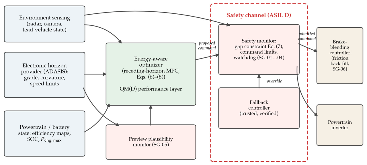
Figure 2.
Wheel braking power against vehicle speed for the representative deceleration event of Section 5.1 (m = 2000 kg, 100 km/h to 50 km/h). Hard braking (|a| = 3 m/s2) exceeds the 60 kW regeneration limit throughout the event, so ≈52% of the kinetic-energy change is dissipated in the friction brakes; gentle braking (|a| = 1 m/s2) remains inside the envelope and essentially all of the energy is recoverable.
Figure 2.
Wheel braking power against vehicle speed for the representative deceleration event of Section 5.1 (m = 2000 kg, 100 km/h to 50 km/h). Hard braking (|a| = 3 m/s2) exceeds the 60 kW regeneration limit throughout the event, so ≈52% of the kinetic-energy change is dissipated in the friction brakes; gentle braking (|a| = 1 m/s2) remains inside the envelope and essentially all of the energy is recoverable.
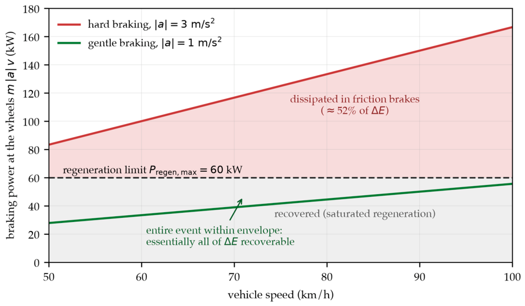

Table 1.
Hazard analysis and risk assessment (HARA) for the energy-aware longitudinal control feature, with derived safety goals and their allocation. S, E, C, and the resulting ASILs are engineering judgements for the assumed item definition and must be revalidated for a specific programme (per ISO 26262-3).
Table 1.
Hazard analysis and risk assessment (HARA) for the energy-aware longitudinal control feature, with derived safety goals and their allocation. S, E, C, and the resulting ASILs are engineering judgements for the assumed item definition and must be revalidated for a specific programme (per ISO 26262-3).
| ID | Malfunctioning behaviour (worst-case operational situation) | S | E | C | ASIL | Safety goal and allocation |
|---|---|---|---|---|---|---|
| HE-01 | Fails to provide the required deceleration for a braking, slow, or stopped lead vehicle (highway, high speed, dense traffic) | 3 | 4 | 3 | D | SG-01: always achieve the deceleration needed to hold the minimum safe gap; hand off to AEB beyond feature limits. → Safety channel |
| HE-02 | Unintended traction/acceleration that closes the gap or exceeds the safe speed (approaching slower or queued traffic at speed) | 3 | 4 | 3 | D | SG-02: never command traction that cuts the gap below the safe distance or drives v above v_lim. → Safety channel |
| HE-03 | Excessive or unintended hard deceleration (highway, close follower) | 3 | 4 | 2 | C | SG-03: keep commanded deceleration and jerk within the calibrated envelope; harder braking only via validated AEB. → Safety channel (D if judged C3) |
| HE-04 | Stale or late command from solver timeout or preview latency — no response to a cut-in or sudden lead braking (urban/highway) | 3 | 4 | 3 | D | SG-04: a safe command within the control deadline; on timeout, the safety controller takes over. → Safety channel (watchdog + fallback) |
| HE-05 | Over-speed from erroneous electronic-horizon speed-limit or curvature data (approaching a curve or a limit reduction) | 3 | 3 | 2 | B | SG-05: bound and plausibility-check preview influence; degrade to sensor-only ACC on implausible or absent data. → Preview plausibility monitor |
| HE-06 | Regenerative under-braking: commanded regen exceeds what is available and friction is not filled in (downhill or gap-closing; cold or high-SOC battery) | 3 | 3 | 3 | C | SG-06: actual deceleration must meet the request regardless of regen availability (guaranteed friction back-fill). → Brake-blending controller |
| HE-07 | Abrupt regen dropout or one-pedal deceleration mismatch surprising the driver or follower (highway lift-off, close follower) | 2 | 4 | 2 | B | SG-07: keep deceleration transitions within calibrated jerk limits and predictable. → Blending controller + energy-layer jerk limit |
| HE-08 | String-unstable or oscillatory speed command induced by the energy weighting (highway platoon, dense traffic) | 2 | 3 | 2 | A | SG-08: guarantee closed-loop stability and bounded response; the energy weighting must not destabilise gap regulation. → Controller design/verification |
Disclaimer/Publisher’s Note: The statements, opinions and data contained in all publications are solely those of the individual author(s) and contributor(s) and not of MDPI and/or the editor(s). MDPI and/or the editor(s) disclaim responsibility for any injury to people or property resulting from any ideas, methods, instructions or products referred to in the content. |
© 2026 by the authors. Licensee MDPI, Basel, Switzerland. This article is an open access article distributed under the terms and conditions of the Creative Commons Attribution (CC BY) license (http://creativecommons.org/licenses/by/4.0/).
Copyright: This open access article is published under a Creative Commons CC BY 4.0 license, which permit the free download, distribution, and reuse, provided that the author and preprint are cited in any reuse.