
Submitted:
31 July 2026
Posted:
03 August 2026
You are already at the latest version
Abstract
Non-cooperative sensing using signals of opportunity traditionally requires an explicit reference signal for target detection and localization. This paper introduces a referencefree sensing framework in which target geometry is inferred directly from the received waveform rather than by comparison with an acquired or reconstructed illuminator signal. The proposed framework is implemented using the Ranging, Detection, Imaging, Communications, Approach, and Landing (RaDICAL) architecture, which combines a hybrid Dish–Sparse Uniform Circular Array (SUCA) receiver with Starlink downlink transmissions as spaceborne illuminators of opportunity. Deterministic Multifrequency Dither (DMD) applied across the SUCA elements transforms spatial diversity into unique composite waveform signatures. A unified electromagnetic and signal-processing model is developed that combines spherical-wave propagation, parabolic focusing, deterministic multifrequency modulation, and QRbased waveform-domain hypothesis testing for direct target localization. Numerical simulations together with link-budget analysis demonstrate the feasibility of the proposed approach. Single-dwell detection of 0 dBsm targets is achieved at physical signal-to-noise ratios near 0 dB, while near-unity detection probability is obtained above 10 dB SNR under controlled false-alarm conditions. The results demonstrate that commercial Starlink LEO communication satellites can serve as practical illuminators of opportunity for reference-free non-cooperative sensing without requiring acquisition or reconstruction of the transmitted illuminator waveform.
Keywords:
non-cooperative sensing
; starlink signals of opportunity
; LEO communication satellites
; reference-free sensing
; deterministic multifrequency dither
; waveform-domain processing
; QR decom-position
1. Introduction
Passive remote sensing using signals of opportunity has emerged as an important research area because it enables target detection and localization without requiring active transmission. By exploiting existing illuminators of opportunity (IoOs), including FM broadcast, cellular, digital television, navigation satellites, and more recently low-Earth-orbit (LEO) communication satellites, passive sensing systems offer covert operation, low deployment cost, spectral coexistence, and continuous global coverage [3,8,14,15]. These characteristics have made passive sensing increasingly attractive for defense, surveillance, Earth observation, and remote sensing applications [9].
Despite numerous architectural variations, virtually all passive sensing systems rely on an explicit or reconstructed reference waveform for target detection and localization. Although reference acquisition techniques have evolved considerably, the underlying correlation-based processing paradigm has remained essentially unchanged since the earliest passive radar demonstrations [8,15].
This paper proposes a fundamentally different sensing framework termed RaDICAL (Ranging, Detection, Imaging, Communications, Approach, and Landing), which eliminates the requirement for an explicit reference signal [26,27,28]. Instead of comparing received echoes with a transmitted waveform replica, the proposed approach employs Deterministic Multifrequency Dither (DMD) together with dictionary-based waveform recognition. Target geometry is directly embedded into the received composite waveform, allowing localization without explicit transmitter synchronization or reference-signal reconstruction.
Conventional passive radar systems employ bistatic or multistatic configurations that process two logically distinct signal paths: a reference signal representing the direct-path transmission from the illuminator of opportunity and a surveillance signal containing target-scattered echoes [2,4,22]. Target detection is subsequently performed by correlating the surveillance signal with either the directly received or a reconstructed reference waveform. Consequently, synchronization requirements, reference-channel contamination, multipath propagation, and hardware complexity remain important practical challenges [11,19].
Numerous approaches have attempted to reduce hardware complexity by reconstructing the reference waveform using blind demodulation, signal separation, or statistical estimation [5,6,12,16,19]. Although these methods eliminate the need for a dedicated reference antenna, they remain fundamentally reference-dependent because target detection and localization continue to rely on correlation with an explicit or reconstructed transmitter waveform.
There is growing demand for persistent, low-cost, and globally deployable sensing systems that operate without active emissions or cooperative transmitters. Recent work has demonstrated non-cooperative sensing using LEO communication satellites such as Starlink and OneWeb as illuminators of opportunity [6,13,16,18,23]. However, these systems remain fundamentally reference-dependent, requiring either an explicit reference channel or reconstruction of the transmitted waveform to perform target detection and localization.
In contrast, the proposed Dish–SUCA RaDICAL architecture shown in Fig. 1 eliminates the need for a dedicated reference receiver. The architecture combines two complementary components. First, the parabolic reflector provides aperture gain that enables practical operation with relatively low-EIRP Starlink downlinks. Second, the Sparse Uniform Circular Array (SUCA) employs Deterministic Multifrequency Dither (DMD) to transform target geometry into a unique composite waveform. Consequently, target detection and localization are achieved through direct waveform correlation with precomputed dictionary entries rather than cross-correlation with an acquired or reconstructed reference waveform. The combination of aperture-level signal enhancement and waveform-domain spatial encoding forms the basis of the proposed reference-free non-cooperative sensing framework.
The principal contributions of this paper are summarized as follows:
- 1.
- A reference-free non-cooperative sensing architecture is introduced in which the Dish–SUCA receive aperture actively participates in the sensing process through Deterministic Multifrequency Dither (DMD), transforming target geometry into a unique composite waveform signature.
- 2.
- A reference-free non-cooperative sensing framework is developed that eliminates the need for a dedicated reference channel and transmitter synchronization by performing target detection and localization directly from geometry-dependent waveform responses.
- 3.
- A physics-based electromagnetic model of the Dish–SUCA assembly is formulated using geometrical optics and Huygens–Kirchhoff propagation, establishing the relationship between target position and the resulting composite waveform.
- 4.
- A waveform-domain detection and localization methodology based on dictionary matching and QR-domain correlation is developed for direct estimation of target range and direction from the generated waveform signatures.
- 5.
- Numerical validation through detection analysis, ROC evaluation, disturbance robustness studies, and link-budget assessment demonstrates the feasibility of single-dwell reference-free non-cooperative sensing using Starlink signals of opportunity.
Figure 1.
(a) Reference-free non-cooperative sensing geometry. (b) Dish–SUCA receiver configuration.
Figure 1.
(a) Reference-free non-cooperative sensing geometry. (b) Dish–SUCA receiver configuration.
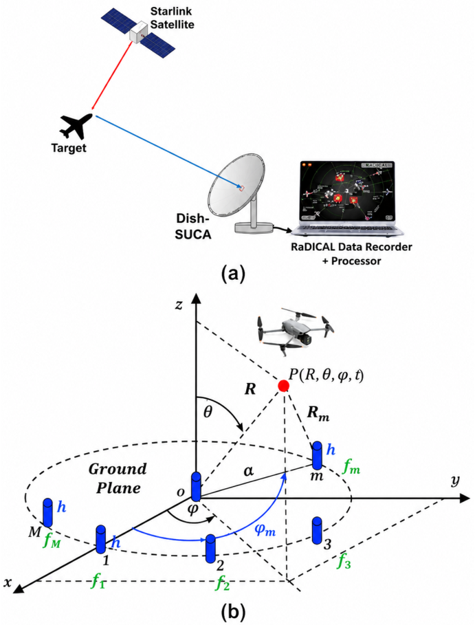
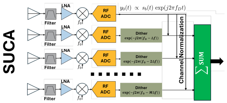
Figure 2.
Receiver architecture of the proposed Dish–SUCA reference-free non-cooperative sensing system.
Figure 2.
Receiver architecture of the proposed Dish–SUCA reference-free non-cooperative sensing system.
1.1. Spaceborne Passive Radar Background
The limitations associated with reference-dependent passive sensing become even more significant when spaceborne illuminators of opportunity are employed. Low-Earth-orbit (LEO) broadband communication constellations, particularly Starlink, have recently emerged as attractive non-cooperative signal sources because of their global coverage, high effective isotropic radiated power (EIRP), and wide instantaneous bandwidth. These characteristics have stimulated extensive research into Starlink-based passive radar for surveillance, imaging, remote sensing, and opportunistic positioning applications. The present work extends the reference-free RaDICAL framework introduced in [28] to the domain of spaceborne illuminators.
Numerous theoretical and experimental investigations have explored the feasibility of exploiting Starlink downlink transmissions for passive sensing [5,6,12,13,16,18,19,23]. These studies include signal characterization, passive imaging, target detection, and navigation using LEO communication satellites. Representative prior work is summarized in

Table 1.
Representative Starlink-Based Passive Sensing Studies
| Reference | Main Contribution | Processing Paradigm |
|---|---|---|
| [19] | First theoretical and experimental investigation of Starlink passive radar. | Reference-dependent bistatic processing. |
| [2] | Comprehensive survey of broadband LEO communication satellites for passive radar. | System-level feasibility analysis. |
| [16] | Blind burst detection and signal parameter estimation from Starlink transmissions. | Navigation and signal characterization. |
| [6] | First experimental demonstration of Starlink-based passive radar imaging. | Reference-dependent bistatic imaging. |
| [23] | Burst detection and characterization of Starlink downlink signals. | Navigation-oriented signal processing. |
| [13] | Evaluation of Starlink as an opportunistic positioning, navigation, and timing (PNT) source. | Positioning and timing. |
| [18] | Experimental comparison of Starlink and OneWeb signals for passive radar. | Signal quality assessment. |
| [17] | Foundational theory of planar and circular arrays relevant to Dish–SUCA geometry and focal-plane sampling. | Electromagnetic antenna theory. |
Although these investigations differ substantially in application and implementation, they share a common architectural characteristic: all remain fundamentally reference-dependent. Target detection is performed by cross-correlating the surveillance signal with either a directly received or reconstructed replica of the transmitted waveform. Consequently, these systems continue to require reference-signal acquisition or estimation, external synchronization, and conventional bistatic processing.
In contrast, the approach proposed in this paper extends the reference-free RaDICAL architecture to LEO communication satellites. Rather than reconstructing the transmitted waveform, the proposed Dish–SUCA receiver directly converts target geometry into deterministic composite waveform signatures through spatial–frequency encoding. Localization is then performed by dictionary matching of the received waveform, eliminating the reference channel while preserving the information required for target detection and localization.
1.2. Paper Organization
The remainder of this paper is organized as follows. Section 2 introduces the proposed Dish–SUCA RaDICAL architecture, including the array geometry, reflector focusing properties, and deterministic multifrequency dither mechanism. Section 3 develops the signal and waveform formation model together with the numerical implementation and simulation methodology. Section 4 presents the detection performance, disturbance analysis, and power-budget evaluation under representative Starlink illumination conditions. Finally, Section 5 concludes the paper and discusses the implications of the proposed reference-free sensing framework for globally deployable space-assisted passive radar systems.
2. Dish–SUCA Aperture Characteristics
The proposed Dish–SUCA receiver combines a conventional parabolic reflector with a Sparse Uniform Circular Array (SUCA) positioned in the focal region, as illustrated in Fig. 1. The parabolic reflector provides high aperture gain and enhances the received signal power, whereas the SUCA performs deterministic spatial–frequency encoding through controlled multifrequency diversity. The combination of these two components enables simultaneous aperture-level signal enhancement and waveform-level spatial encoding, which forms the basis of the proposed reference-free sensing framework.
Because the reflector exhibits a highly directive radiation pattern, the instantaneous angular field of view of the Dish–SUCA assembly is inherently limited. To quantify this limitation, the reflector is analyzed using the electromagnetic reciprocity principle, according to which identical radiation characteristics are obtained in transmission and reception. Consequently, the receive performance of the proposed system can be evaluated through an equivalent transmit analysis, allowing estimation of the accessible angular search sector and subsequent development of the waveform-domain signal model.
2.1. Aperture-Field Modeling Using Geometrical Optics
All subsequent electromagnetic field propagation and signal modeling are performed within a unified MATLAB framework, enabling flexible parametric studies and efficient system-level evaluation of the proposed Dish–SUCA receiver. Because the reflector is electrically large (), the reflector geometry satisfies (Fig. 1), and the angular field of view is relatively narrow, polarization variations across the illuminated aperture are small. Under these conditions, the reflector fields can be accurately represented using the scalar Huygens–Kirchhoff radiation integral, while the aperture field distribution is obtained using geometrical optics (GO) [24].
This hybrid GO/Huygens–Kirchhoff formulation eliminates the need for computationally intensive full-wave electromagnetic simulations, reducing the computational burden by several orders of magnitude while preserving the physical accuracy required for the waveform-domain sensing methodology developed in this paper.
The adopted modeling approach is consistent with previously validated electromagnetic field-prediction techniques developed for planar near-field antenna measurements. In particular, microwave holographic back-propagation of a focused parabolic reflector was experimentally verified in the NASA Glenn Research Center Horizontal Planar Near Field (HPNF) facility, demonstrating sub-percent reconstruction accuracy of the near-field intensity distribution at an axial distance of 10 m in the X-band [29]. These experimental results provide additional confidence in the reflector-field modeling methodology employed here.
The field radiated by each SUCA feed element is first projected onto the reflector surface and subsequently reflected to form the complex aperture field distribution over the dish aperture. For observation points satisfying , the radiated field may be represented by the scalar aperture field through the Huygens–Kirchhoff radiation integral [7,10],
where denote the aperture coordinates, is the distance between an aperture point and the observation point , is the free-space wavenumber, and A denotes the physical aperture area.
To illustrate the GO formulation, consider the representative ray geometry shown in the two-dimensional meridian cross-section of the parabolic reflector in Fig. 3.
A representative ray segment , radiated by a SUCA element located at , intersects the reflector surface at the point and is subsequently reflected toward the aperture plane . According to the law of specular reflection, , the reflected ray segment reaches the aperture at the point . Consequently, the total optical path consists of the two segments
where denotes the feed-element position, is the reflection point on the parabolic surface, and is the corresponding point in the aperture plane.
Within the GO approximation, the aperture-field amplitude is determined primarily by free-space spreading and is therefore proportional to , whereas the phase is proportional to the total optical path length . The resulting complex aperture field associated with the mth SUCA element can therefore be written as
The complete three-dimensional formulation is presented in Appendix A.
The objective of the GO analysis extends beyond prediction of the reflector radiation pattern. More importantly, it provides the geometry-dependent complex coefficients associated with each SUCA element, which constitute the physical basis of the proposed waveform-domain sensing methodology. As the target position changes, the aperture-field distribution and the corresponding SUCA channel responses vary deterministically, producing distinct composite waveforms that can subsequently be identified through dictionary-based matching.
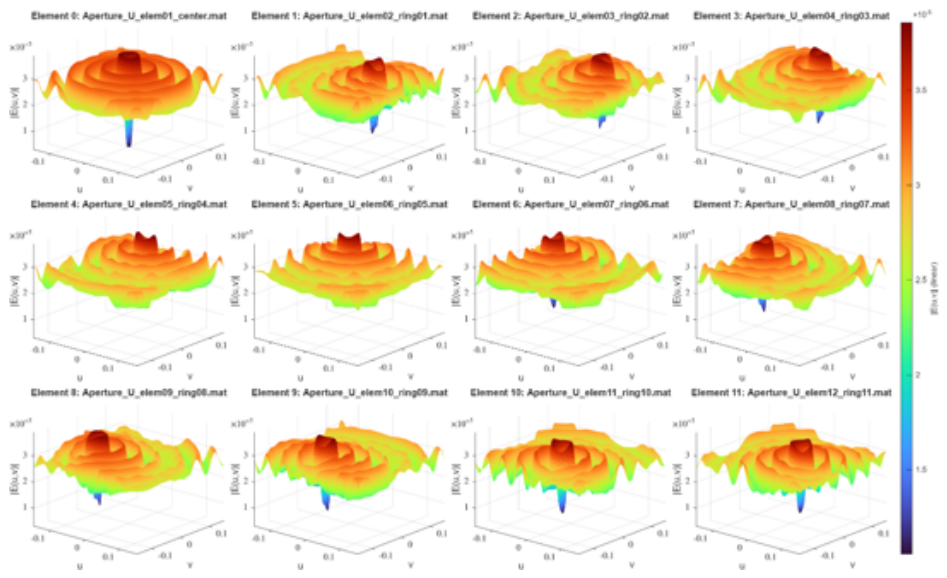
Figure 4(a) and Figure 4(b) illustrate the magnitude and phase distributions of the complex aperture field generated by the 12-element SUCA, consisting of 11 uniformly spaced ring elements and one central reference element. The simulation parameters are summarized in Table 2. The reflector diameter was selected to represent a practical Ku-band Starlink-class ground receive dish.
As shown in Fig. 4(a), the aperture-field magnitude distributions are smooth and strongly apodized by the finite reflector aperture. For each SUCA element, reaches its maximum within the illuminated region and gradually decreases toward the reflector rim, consistent with free-space propagation and the projected feed illumination.
The corresponding phase distributions shown in Fig. 4(b) exhibit the expected GO behavior. For the central element, the phase is nearly rotationally symmetric, indicating an approximately on-axis wavefront across the aperture. For the ring elements, the phase fronts remain largely concentric but are displaced and slightly distorted. These phase variations represent the combined effects of off-axis illumination (beam steering), residual defocus, and finite-range propagation. Most importantly, they constitute deterministic, element-dependent phase signatures that provide the spatial diversity required for the proposed waveform-domain encoding.
Once the aperture-field distributions have been determined, the corresponding partial radiation patterns follow directly from the Huygens–Kirchhoff radiation integral in (1). The resulting element patterns exhibit systematic variations in both beam pointing and phase structure. Consequently, each SUCA element produces a distinct complex channel response, providing the physical basis for the deterministic waveform signatures developed in the following sections.
The resulting partial radiation patterns , expressed in direction-cosine () coordinates at , are shown in Fig. 5. Each beam is tilted by approximately
in the direction opposite to the lateral displacement of the corresponding feed element. Consequently, the intrinsic angular coverage of the reflector is approximately
To provide wide-area coverage, the Dish–SUCA assembly is therefore assumed to be mounted on a mechanical pointing platform capable of steering the reflector toward the desired observation sector.
Figure 5.
Partial radiation patterns of the individual SUCA elements in direction-cosine () coordinates.
Figure 5.
Partial radiation patterns of the individual SUCA elements in direction-cosine () coordinates.
2.2. Geometrical-Optics Modeling of the Dish–SUCA Assembly in Receive Mode
Figure 6 illustrates the receive-mode geometry used throughout this paper. The parabolic reflector is represented, in receive mode, by an equivalent (aperture-plane) complex field distribution on the plane with aperture coordinates . A generic aperture point is denoted . The SUCA provides receive channels indexed by , where each element is located in the focal region at .
Consider a point target (e.g., a drone) located at . In receive mode, the target-scattered field illuminates the dish aperture plane . Let an aperture point be , where are the aperture-plane coordinates. The target-to-aperture distance is
The resulting complex aperture distribution induced by the target echo is modeled as a spherical wave across the aperture,
where is the wavenumber, [1] is a complex coefficient that absorbs the target scattering amplitude/phase, is the distance from a target to Starlink satellite, is equivalent isotropic radiated power toward the target, and is the target radar cross section.
For each aperture sample , the corresponding receive-mode GO path from the aperture to the mth SUCA element is represented by
where and are defined in Appendix A. Combining the target-to-aperture distance with the receive-mode GO path from aperture to the mth element yields the total path
Each SUCA element coherently collects contributions from all illuminated discrete aperture samples. Accordingly, the complex baseband signal in the mth channel is modeled as the coherent sum
where denotes the number of discrete aperture samples. Equation (8) therefore defines the geometry-dependent complex response of the Dish–SUCA assembly. Because the total path length varies with target position, each hypothesized target location produces a distinct vector of complex channel responses . These responses constitute the physical signatures that are subsequently transformed into waveform-domain representations and used for target detection and localization through dictionary matching.
2.3. Multifrequency Dither and Waveform Synthesis
According to the RaDICAL receiver block diagram shown in Fig. 2, DMD is implemented by applying a known local-oscillator (LO) offset to the mth channel. The corresponding effective channel frequency and wavenumber are
An important property of the multifrequency dither is its ability to focus the field at a designated spatial location when the circular array operates in the transmit mode [21]. In this case, the mth array element radiates at its assigned frequency , and the propagation phase accumulated along the corresponding path is determined by the wavenumber .
In the receive mode, however, all SUCA elements are illuminated by the same target-scattered signal at the signal-of-opportunity frequency . Consequently, the naturally received phase is governed by the wavenumber k, and the multifrequency focusing condition does not arise directly. To reproduce the transmit-mode phase relationship in the receiver, the phase of each SUCA channel must therefore be transformed from k to its assigned effective wavenumber .
According to (8), the complex baseband signal in the mth channel can be expressed as
where and are the generally unequal equivalent paths governing the signal phase and magnitude, respectively, and C contains factors common to all channels. For simplicity, C is assumed to be a real positive constant common to all channels. Any fixed complex channel calibration factors may be removed during receiver calibration and therefore do not affect the proposed phase-transformation procedure. Taking the complex logarithm of (10) gives
The required receive-channel phase transformation is then performed in the complex-logarithm domain as
After exponentiation, the transformed channel response becomes
Thus, the complex-logarithm operation modifies only the propagation phase associated with the mth channel, replacing k by while preserving its physically modeled magnitude. Consequently, the the transformed receive channels become mathematically equivalent to those of a transmitting SUCA employing DMD, thereby recovering the corresponding waveform-domain spatial-focusing behavior.
The multifrequency offsets convert these spatially varying channel responses into a deterministic time-varying composite waveform, which can be written as
According to (14), the multifrequency offsets establish a deterministic phase progression across the Dish–SUCA channels. The transformed channel responses combine coherently to focus the receive beam at a prescribed spatial location. As the relative channel phases evolve with time, the receive beam moves through the search volume, and each target location generates a unique composite waveform .
Therefore, a spatial grid can be defined and a dictionary of precomputed composite waveforms generated, with one waveform corresponding to each grid point. Consequently, target localization could be performed by correlating the received waveform with the precomputed dictionary. Once a matching waveform is identified, the corresponding target range and angular coordinates are immediately revealed. The details of the correlation algorithm are presented in the following subsection.
Figure 7 illustrates the behavior of the instantaneous composite waveforms defined in (14) for several representative target positions with the same nominal range , while the lateral target coordinates vary according to the grid in Table 2. It can be seen that even modest lateral shifts produce substantial and clearly distinguishable changes in the composite signal (14). Consequently, variations in range and angle translate into measurable changes in amplitude modulation, phase evolution, and complex-plane trajectory.
These results demonstrate that DMD provides an effective mechanism for embedding spatial information into the received waveform. This property enables robust dictionary-based detection and localization using a single composite signal stream, forming the core operational principle of the RaDICAL reference-free passive radar architecture.
2.4. Satellite Dynamics, Common-Mode Doppler, and Output Normalization
A key challenge for passive radar using low-Earth-orbit (LEO) satellites is the impact of satellite motion and carrier-frequency offsets. Starlink satellites travel at velocities of approximately , producing Doppler shifts of several tens of kilohertz at Ku-band. After downconversion with a fixed local oscillator (LO), these effects appear primarily as a common carrier-frequency offset and a linear phase rotation in time. Let denote the complex baseband modulation of the Starlink downlink. Incorporating the deterministic SUCA frequency dither and the effective Doppler shift , the complex baseband signal at the mth SUCA channel can be written as
where denotes the geometry-dependent complex channel coefficient implied by (14). Because the physical dimensions of the Dish–SUCA assembly are many orders of magnitude smaller than the satellite range, the differential radial velocity across the aperture is negligible. Consequently, the satellite-induced Doppler shift appears as a common-mode term shared by all receive channels.
As shown in Figure 2, the central SUCA element () does not employ frequency dither. Its baseband signal is therefore
To remove illumination modulation and common Doppler rotation, each channel is normalized with respect to the central element:
Equation (17) shows that normalization removes the common multiplicative component shared across channels, including the illumination modulation and the common Doppler phase term associated with LEO satellite motion. At the same time, it preserves the deterministic spatio-temporal encoding through the geometry-dependent coefficients and the known frequency offsets . This result is particularly important because it isolates the geometry-dependent channel coefficients from the unknown illuminator waveform and the common satellite-motion effects, leaving only the information required for waveform-domain localization.
Figure 8 presents the element0–normalized composite waveforms defined in (17). Compared to the unnormalized responses in Figure 7, the temporal oscillations appear smoother and less dispersed across target positions. Although normalization reduces absolute amplitude variation across hypotheses, the relative phase relationships that encode range–angle information remain intact. Because the reference element is located at the center of the SUCA disk (with zero lateral displacement), it observes the most symmetric receive-field distribution within the focal region. Consequently, the central element provides a stable, typically higher-SNR reference for normalization, which suppresses common-mode effects without distorting the geometry-dependent waveform structure used for detection and localization.
Normalization suppresses the common Doppler component associated with LEO satellite motion; however, the satellite itself continues to move angularly across the sky. For the reflector considered here, the effective receive sector of approximately – provides a useful angular tolerance before significant gain reduction occurs. Within this sector, tracking requirements are relaxed and short-term operation without continuous mechanical repositioning is feasible. If the available link-budget margin discussed later permits, the Dish diameter may be reduced, provided that the available link-budget margin is sufficient to maintain the required detection probability and widening the instantaneous receive sector, thereby relaxing pointing requirements.
A practical consequence of the normalization procedure is that the receiver does not require carrier-phase synchronization with a specific illuminator. Because the geometry-dependent information is extracted from the normalized Dish–SUCA response through dictionary matching, moderate changes in illuminator characteristics can be tolerated. A detailed analysis of multi-satellite selection and handover strategies is beyond the scope of this paper and is left for future work.
3. Waveform-Domain Detection and Localization
Unlike conventional passive radar architectures that estimate delay, Doppler, or angle-of-arrival (AOA) observables, the proposed RaDICAL receiver performs localization directly in the waveform domain. The target state is inferred from the composite waveform generated by the Dish–SUCA geometry and encoded by DMD.
As shown in the preceding sections, each target location produces a unique composite waveform. This property enables target range and AOA to be estimated by constructing a dictionary of expected waveforms and identifying the entry that best matches the received signal.
A discrete grid of candidate target locations is first defined, and the corresponding predicted composite waveforms are assembled into a dictionary. The received waveform is then compared with this dictionary, and the hypothesis producing the highest normalized correlation is selected as the estimated target position.
To improve numerical robustness, the dictionary is orthogonalized using QR decomposition before the matching process. This reduces inter-hypothesis coherence and improves discrimination between closely spaced target locations without increasing computational complexity. The overall processing chain therefore remains compact, reference-free, and well suited for real-time implementation.
3.1. Dictionary Construction
Let denote the discrete-time vector formed from the normalized multi-channel signals in (17). For a hypothesized target state , the forward Dish–SUCA model described by (8) generates the predicted normalized waveform
The measurement model is therefore
where a represents an unknown complex scaling coefficient that accounts for residual propagation loss and target RCS, while denotes additive thermal noise. Since the normalization procedure removes the common illumination and Doppler components, depends only on the target geometry.
After defining the discrete search grid , the waveform dictionary is constructed as
3.2. QR Orthogonalization and Correlation-Based Selection
Because neighboring target hypotheses may generate partially coherent waveforms, the dictionary may exhibit significant column correlation and poor numerical conditioning. Therefore, a QR factorization
is applied to obtain an orthonormal basis spanning the same column space as . The dictionary atoms and the received waveform are then projected onto this orthonormal basis according to
This transformation improves numerical conditioning while preserving the underlying signal subspace and the physical similarity between neighboring target hypotheses.
Target localization is then performed by maximizing the normalized complex correlation
The estimated target state is therefore
The normalized correlation metric is equivalent to a scale-invariant matched filter and, under an unknown complex target amplitude, corresponds to the maximum-likelihood estimator. No mean subtraction is required because the complex baseband waveforms are already zero-mean in the absence of a target signal.
The QR transformation does not modify the physical information contained in the waveform dictionary. Instead, it provides an orthonormal representation that improves numerical conditioning and reduces sensitivity to dictionary coherence when neighboring target locations produce similar waveform signatures.
4. Baseline RaDICAL Performance Validation
Table 2 summarizes the physical and simulation parameters used throughout the numerical study. The objective of this section is to evaluate the fundamental feasibility of the proposed Dish–SUCA RaDICAL architecture and to quantify the extent to which geometry-dependent waveform signatures enable reliable target detection and localization.
Performance is evaluated using four complementary metrics that assess detection capability, localization accuracy, waveform separability, and robustness under representative impairment conditions. Two processing configurations are considered:
- BASE: Direct DMD composite waveforms without Element0 normalization.
- Element0 Normalized: DMD composite waveforms normalized with respect to the central SUCA element according to (17).
The results provide engineering-level validation of the central RaDICAL concept, namely, that target geometry can be encoded into distinct waveform signatures and subsequently recovered through waveform-domain dictionary matching without requiring a dedicated reference channel.
4.1. Detection Probability Versus SNR
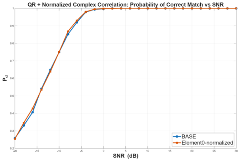
This metric evaluates the detection performance of the proposed waveform-domain sensing framework in the presence of additive white Gaussian noise (AWGN). For each SNR value, noisy multi-channel target responses are generated and processed using the QR-based waveform matching procedure described in Section 3. The probability of detection is defined as the fraction of Monte Carlo trials in which the correct target hypothesis produces the highest normalized correlation score. The SNR is referenced to the average power of the corresponding dictionary waveform.
Figure 9 exhibits the expected threshold behavior of the proposed waveform-domain detector. The probability of detection increases rapidly near approximately dB SNR and approaches unity above approximately dB. The relatively steep transition indicates that the geometry-dependent waveform signatures remain highly distinguishable even in the presence of substantial additive noise.
A particularly important result is that this level of detection performance is achieved using a single microsecond-scale dwell without reference-channel reconstruction, delay estimation, Doppler processing, or ambiguity-function evaluation. Detection is performed entirely through waveform-domain matching of the normalized Dish–SUCA response.
The BASE and Element0 Normalized configurations exhibit nearly identical performance. The slight improvement observed after normalization is consistent with the suppression of common-mode amplitude variations, indicating that detection performance is governed primarily by the phase-structured waveform encoding introduced by DMD rather than by absolute signal amplitude.
Figure 9.
Probability of correct detection versus input SNR for QR-based normalized complex correlation. BASE denotes direct dictionary matching, whereas Element0 Normalized denotes normalization with respect to the central SUCA element prior to waveform matching.
Figure 9.
Probability of correct detection versus input SNR for QR-based normalized complex correlation. BASE denotes direct dictionary matching, whereas Element0 Normalized denotes normalization with respect to the central SUCA element prior to waveform matching.
4.2. Power Budget Validation
To ensure reliable target detection, the time-averaged received power at the SUCA combiner output must exceed the minimum level required by the detector. This requirement may be written as
where [dBm] is the thermal-noise power within the receiver bandwidth [Hz] at 290 K, is the receiver noise figure, and denotes the coherent processing gain. Based on the detection results presented in the previous subsection, an operating point of dB was selected, which provides a probability of detection close to unity without requiring additional coherent processing gain ().
The link-budget analysis of the proposed RaDICAL architecture is presented in Figure 10 and Figure 11. The analysis was performed for target ranges of 1 km and 10 km using the same lateral dictionary grid defined in Table 2.
At a target range of approximately km, the lateral dictionary spacing corresponds to an angular sampling interval of
whereas at km the same spatial grid produces
According to the literature summarized in Table 1, the angular sampling adopted in this study is finer than the angular resolution typically reported for existing Starlink passive-radar demonstrations.
The predicted received power indicates that reliable single-dwell detection is achieved for illuminator EIRPs of approximately 10 dBW at a target range of 1 km and 30 dBW at a target range of 10 km. Furthermore, when an illuminator EIRP of 30 dBW is available, the link-budget analysis indicates that the reflector diameter can be reduced from 1.4 m to approximately 0.8 m while maintaining the required detection margin. This substantially reduces the physical size of the receiver, making the proposed RaDICAL architecture compatible with compact, low-cost ground installations.
Particularly noteworthy is that the predicted detection performance is achieved using a single dwell of only s. Unlike conventional passive radar systems, which often rely on substantial coherent integration to accumulate processing gain, the proposed architecture derives its discrimination capability primarily from geometry-dependent waveform encoding and waveform-domain dictionary matching. The short dwell duration enables high update rates and rapid revisit capability, reduces sensitivity to Doppler decorrelation, satellite motion, and platform instability, and minimizes latency between illumination and target declaration, which is particularly important for time-sensitive surveillance applications.
Taken together, the link-budget and detection results demonstrate both the physical and algorithmic feasibility of the proposed RaDICAL architecture. They indicate that Starlink downlinks can provide sufficient illumination for reliable single-dwell operation without transmitter-side modification or cooperation, enabling a broadly deployable passive radar capability for terrestrial and maritime surveillance under operational Starlink illumination.
4.3. Probability of Detection Versus Physical SNR
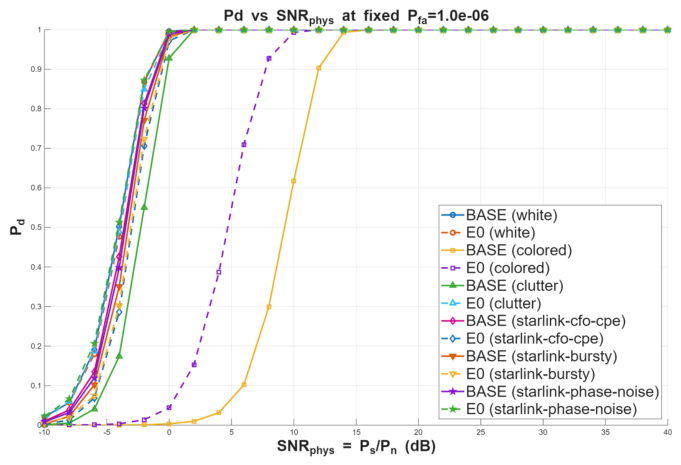
Figure 12 presents the detection performance of the proposed waveform-domain detector as a function of the physical receiver-input SNR under a range of representative disturbance conditions. In contrast to the AWGN-only analysis presented in the preceding subsection, the present study incorporates colored noise, compound clutter, residual synchronization errors, burst interference, and oscillator phase noise to evaluate the robustness of the proposed RaDICAL architecture under more realistic operating conditions.
- Additive white Gaussian noise (White),
- Colored AR(1) noise (Colored),
- Compound-Gaussian K-distributed clutter (Clutter),
- Residual carrier-frequency offset and common phase error (CFO/CPE),
- Bursty impulsive interference with narrowband tones (Bursty),
- Oscillator phase noise (Phase Noise).
Figure 12.
Probability of detection versus physical at a fixed false-alarm probability for representative disturbance models. Results are shown for the BASE and Element0 Normalized processing configurations.
Figure 12.
Probability of detection versus physical at a fixed false-alarm probability for representative disturbance models. Results are shown for the BASE and Element0 Normalized processing configurations.
These disturbance models represent practical deviations from the idealized signal model, including non-white receiver noise, non-Gaussian clutter, synchronization mismatch, external interference, and local-oscillator instability. For each disturbance model, the detection threshold is determined from noise-only realizations to maintain a fixed false-alarm probability of , thereby providing a consistent comparison across different noise statistics.
Under nominal AWGN conditions, the proposed waveform-domain detector exhibits a sharp transition from low to near-unity detection probability at relatively low physical SNR, reflecting the strong geometry-dependent waveform separability produced by DMD within the Dish–SUCA architecture. The clutter and phase-noise cases closely follow the AWGN baseline, indicating that normalized waveform matching is largely insensitive to multiplicative amplitude fluctuations and moderate phase distortions. Residual CFO/CPE mismatch and burst interference introduce only a modest SNR penalty, while reliable single-dwell detection is preserved without requiring long coherent integration intervals.
Strongly colored AR(1) noise represents the most challenging disturbance, shifting the detection threshold toward higher SNR because of temporal correlation and the corresponding reduction in effective degrees of freedom. Nevertheless, the detector approaches as increases, preserving the characteristic threshold behavior of the waveform-domain detector.
Overall, the simulation results demonstrate that reliable single-dwell detection () is achieved for of approximately 0–5 dB under AWGN, clutter, phase-noise, and synchronization-error conditions, and within approximately 10 dB under strongly colored noise. These results indicate that the geometry-dependent waveform signatures generated by the Dish–SUCA architecture remain readily distinguishable under a broad range of realistic disturbance conditions. Consequently, reliable single-dwell detection can be achieved without reference-channel reconstruction or extended coherent integration.
4.4. ROC Performance Under White Gaussian Noise
Figure 13 presents the receiver operating characteristic (ROC) curves of the proposed waveform-domain detector for , 0, and dB, where is defined from the GO-predicted received power and the corresponding thermal-noise level, as described in the previous subsection.
At dB, the detector achieves – at . Thus, even when the received signal power is 10 dB below the thermal noise power and only one false alarm per million decisions is permitted, the proposed RaDICAL detector correctly identifies more than 80% of target realizations. This behavior reflects the strong geometry-dependent waveform separability produced by DMD and preserved through QR-based waveform-domain processing.
At dB, the probability of detection exceeds 95% for the same false-alarm constraint. Thus, even when the received signal and thermal noise powers are equal, the proposed detector maintains high detection reliability while preserving strict false-alarm control.
At dB, the ROC curve approaches the ideal detector characteristic () over the entire false-alarm range. In this regime, the geometry-dependent waveform signatures are well separated from the noise background, allowing the waveform-domain detector to achieve near-perfect discrimination.
For extremely low false-alarm probabilities (e.g., ), direct brute-force Monte Carlo estimation would require an impractically large number of simulation trials. Instead, the decision threshold was obtained by extrapolating the upper tail of the empirically measured distribution, which remains smooth and well behaved under Gaussian noise. The resulting ROC curves are consistent with the expected Gaussian-tail behavior and exhibit no evidence of anomalous threshold sensitivity.
Overall, the ROC characteristics demonstrate that the proposed waveform-domain detector achieves detection performance comparable to coherent radar detection while operating in a completely reference-free passive configuration using only a single microsecond-scale dwell. Under thermal-noise-limited conditions, the proposed RaDICAL architecture maintains reliable target detection while controlling the false-alarm probability over the – range. These results further confirm that the geometry-dependent waveform signatures generated by the Dish–SUCA architecture remain sufficiently distinct to enable reliable target discrimination under stringent detection constraints.
5. Conclusion
This paper introduced a reference-free non-cooperative sensing framework, termed RaDICAL, and demonstrated its application using Starlink signals of opportunity. The proposed receiver with Dish–SUCA combines DMD, geometry-dependent waveform encoding, central-element normalization, and QR-based dictionary matching to estimate target position directly in the waveform domain. Unlike conventional passive radar processing, the proposed framework does not require a dedicated reference channel, reconstruction of the transmitted waveform, explicit transmitter synchronization, delay estimation, or conventional Doppler processing.
A physics-based electromagnetic model of the Dish–SUCA assembly was developed using geometrical optics and Huygens–Kirchhoff propagation. The model determines the geometry-dependent complex response of each SUCA channel for a hypothesized target position. Because all receive elements are physically illuminated at the common signal-of-opportunity frequency , their naturally received propagation phases are governed by the wavenumber k. A complex-logarithm phase transformation was therefore introduced to replace the phase wavenumber k in each channel by its assigned effective wavenumber , while preserving the physically modeled channel magnitude.
This complex-logarithm procedure establishes the mathematical equivalence between the passive receiving Dish–SUCA and its transmitting counterpart employing DMD. Consequently, the transformed receive channels reproduce the deterministic inter-element phase law required for coherent focusing at a prescribed three-dimensional spatial point. As the DMD phases evolve during the measurement dwell, the receive beam moves around the prescribed focal point. Each candidate target position therefore produces a distinct composite temporal waveform that can be generated offline and stored as an entry in the waveform dictionary.
Normalization with respect to the central SUCA element suppresses the unknown Starlink illumination modulation and the common-mode Doppler rotation associated with LEO satellite motion while preserving the relative geometry-dependent channel information. Target detection and localization are then performed by comparing the measured normalized composite waveform with the precomputed dictionary using QR-domain normalized correlation.
Numerical simulations demonstrated that neighboring target hypotheses generate distinguishable waveform signatures that can be identified through dictionary-based matching. Monte Carlo results showed reliable single-dwell detection at low physical signal-to-noise ratios and under stringent false-alarm constraints. The proposed detector also maintained robust performance in the presence of colored noise, compound clutter, residual synchronization errors, burst interference, and oscillator phase noise.
Link-budget analysis indicated that representative Starlink downlink illumination can provide sufficient received power for single-dwell operation under the assumed target geometry and receiver parameters. Taken together, the electromagnetic modeling, complex-logarithm receive-phase transformation, spatial-focusing analysis, waveform-domain detection results, ROC evaluation, disturbance studies, and link-budget assessment support the physical and algorithmic feasibility of the proposed architecture.
The central result of this study is that non-cooperative sensing need not depend on an acquired or reconstructed illuminator waveform. Instead, target geometry can be recovered from deterministic composite waveforms generated by transmit-equivalent spatial–frequency focusing within the receiving aperture. Although Starlink transmissions were used as the illuminator in this study, the proposed framework is applicable to a broader class of non-cooperative communication signals of opportunity.
Future work will focus on experimental validation using live Starlink illumination, implementation of a real-time multichannel SDR prototype, and evaluation in dynamic propagation environments. Because RaDICAL estimates the three-dimensional target position during each measurement dwell, successive waveform-domain measurements can also support estimation of target velocity and trajectory. Experimental validation of waveform-domain tracking and multi-target operation will be addressed in future work.
Appendix A. Geometric–Optics Ray Mapping for the Dish–SUCA Aperture Field
This appendix summarizes the geometric–optics (GO) construction used to compute the aperture field distribution employed in (1). The paraboloidal reflector surface is parameterized by
The outward unit normal vector is
Let the SUCA element be located at
The incident unit direction is
Specular reflection gives the outgoing direction
The reflected ray intersects the aperture plane at
The aperture coordinates are therefore
For a given aperture location , the reflector coordinates are obtained by numerically inverting this nonlinear mapping. The reflected path length is
Since SUCA elements lie on the plane , the incident path length is
The total optical path is
Under the GO approximation, each aperture point is illuminated by the field propagating along its associated ray. The complex aperture field is
This field distribution is used as the aperture illumination function in the radiation integral (1).
References
- C. A. Balanis, Antenna Theory: Analysis and Design, 4th ed. Hoboken, NJ, USA: Wiley, 2016.
- R. Blázquez-García, D. Cristallini, M. Ummenhofer, V. Seidel, J. Heckenbach, and D. O’Hagan, “Capabilities and challenges of passive radar systems based on broadband low-Earth-orbit communication satellites,” IET Radar, Sonar & Navigation, vol. 18, no. 1, 2024. [CrossRef]
- F. Colone, F. Filippini, and D. Pastina, “Passive radar: Past, present, and future challenges,” IEEE Aerospace and Electronic Systems Magazine, vol. 38, no. 1, 2023. [CrossRef]
- S. Elgayar and E. Ertin, “On model order estimation in distributed passive radar without reference signal,” in Proc. IEEE Radar Conf., 2016.
- E. Fishler, A. Haimovich, R. S. Blum, L. J. Cimini, D. Chizhik, and R. A. Valenzuela, “MIMO radar: An idea whose time has come,” in Proc. IEEE Radar Conf., 2004, pp. 71–78.
- P. Gómez-del-Hoyo and P. Samczyński, “Starlink-based passive radar for Earth’s surface imaging: First experimental results,” IEEE J. Sel. Topics Appl. Earth Observ. Remote Sens., vol. 17, no. 9, 2024. [CrossRef]
- J. W. Goodman, Introduction to Fourier Optics, 2nd ed. New York, NY, USA: McGraw-Hill, 1996, chs. 3–4.
- H. D. Griffiths and C. J. Baker, An Introduction to Passive Radar. Norwood, MA, USA: Artech House, 2017.
- D. E. Hack, L. K. Patton, and B. Himed, “A unified detection framework for distributed active and passive RF sensing,” in Proc. Asilomar Conf. Signals, Syst., Comput., 2013.
- E. Hecht, Optics, 5th ed. Harlow, U.K.: Pearson, 2017, ch. 10.
- M. Horlbeck, J. Palmer, H. D. Griffiths, and C. J. Baker, “Overview of passive radar and its receiver architectures to enhance safety in civil aviation,” IEEE Microw. Mag., vol. 25, no. 5, 2024. [CrossRef]
- Y. Hu, J. Yi, J. Cheng, X. Wan, and S. Hu, “3-D target tracking for distributed heterogeneous 2-D–3-D passive radar network,” IEEE Sensors J., vol. 23, no. 23, 2023. [CrossRef]
- Z. M. Kassas, J. Khalife, and M. Neinavaie, “Unveiling Starlink for PNT: A trick or a treat?” Navigation, vol. 72, no. 1, 2025.
- R. Liu, W. Dai, and C. Zhang, “Multi-target detection by distributed passive radar systems without reference signals,” in Proc. IEEE Wireless Commun. Netw. Conf. (WCNC), 2021.
- M. Malanowski, Signal Processing for Passive Bistatic Radar. Norwood, MA, USA: Artech House, 2019.
- M. Neinavaie and Z. M. Kassas, “Unveiling Starlink LEO satellite OFDM-like signal structure enabling precise positioning,” IEEE Trans. Aerosp. Electron. Syst., vol. 60, no. 2, pp. 2486–2489, 2024. [CrossRef]
- N. K. Nikolova, “Planar arrays and circular arrays,” Lecture 16, McMaster University. Available: https://www.ece.mcmaster.ca/faculty/nikolova/antenna_dload/current_lectures/L16_Arrays4.pdf.
- R. Blázquez-García et al., “Experimental comparison of Starlink and OneWeb signals for passive radar,” in Proc. Eur. Radar Conf. (EuRAD), 2023.
- A. Sayin, M. Cherniakov, and M. Antoniou, “Passive radar using Starlink transmissions,” in Proc. Int. Radar Symp. (IRS), 2019.
- C. Shi, Y. Wang, S. Salous, J. Zhou, and J. Yan, “Joint transmit resource management and waveform selection strategy for target tracking in distributed phased-array radar networks,” IEEE Trans. Aerosp. Electron. Syst., vol. 58, 2022, . [CrossRef]
- S. Del Prete, M. Barbiroli, and F. Fuschini, “Frequency Diverse Array for Signal Geofencing in Wireless Communications: Does it Work?” IEEE Open Journal of Antennas and Propagation, vol. 6, no. 1, Feb. 2025. [CrossRef]
- M. A. Siddique, U. Wegmüller, I. Hajnsek, and O. Frey, “SAR tomography for spatio-temporal inversion of point-like scatterers in urban areas,” in Proc. IEEE Int. Geosci. Remote Sens. Symp. (IGARSS), 2015.
- W. Stock, C. Hofmann, and A. Knopp, “LEO-PNT with Starlink: Development of a burst detection algorithm based on signal measurements,” arXiv preprint, arXiv:2304.09535, 2023.
- W. L. Stutzman and G. A. Thiele, Antenna Theory and Design, 3rd ed. Hoboken, NJ, USA: Wiley, 2013, ch. 9.
- J. Vierinen, “Building your own SDR-based passive radar on a shoestring,” Hackaday, Jun. 5, 2015. Available: https://hackaday.com/2015/06/05/building-your-own-sdr-based-passive-radar-on-a-shoestring/.
- V. Volman, “Nonlinear SUCA Waveforms and QR-Domain Maximum-Likelihood Detection for Passive RaDICAL Monostatic Radar,” TechRxiv, 2025. Available: https://www.techrxiv.org/doi/full/10.36227/techrxiv.176404163.34190144/v1.
- V. Volman and J. A. Nessel, “Monostatic waveform-domain passive radar for detection and localization using a sparse circular array with deterministic frequency dither,” Sensors, vol. 26, Art. no. 3816, 2026, . [CrossRef]
- V. Volman and J. B. Stetson, “Super-angular and range-resolution with phased-array antenna and multifrequency dither,” U.S. Patent 8,730,095, May 20, 2014.
- S. W. Waldstein, V. Volman, D. A. Rinehart, J. M. Downey, B. L. Schoenholz, F. A. Miranda, and L. S. Schisler, “Holographic determination of E-field intensity of a converging beam used for wireless power transfer,” presented at the 2025 URSI North American Radio Science Meeting, NASA Glenn Research Center, 2025.
Figure 3.
Geometrical-optics ray construction in the reflector meridian plane.
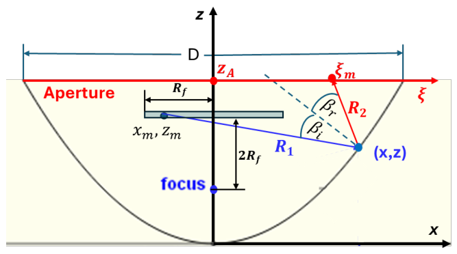
Figure 4.
Complex aperture-field distributions generated by the Dish–SUCA assembly: (a) magnitude and (b) phase.
Figure 4.
Complex aperture-field distributions generated by the Dish–SUCA assembly: (a) magnitude and (b) phase.
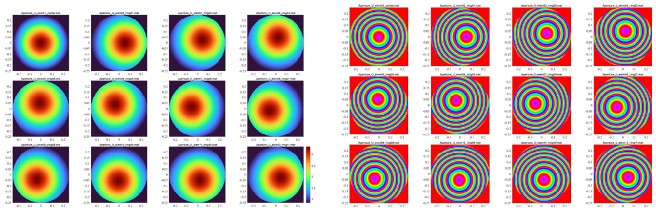
Figure 6.
Receive-mode geometry of the Dish–SUCA assembly.
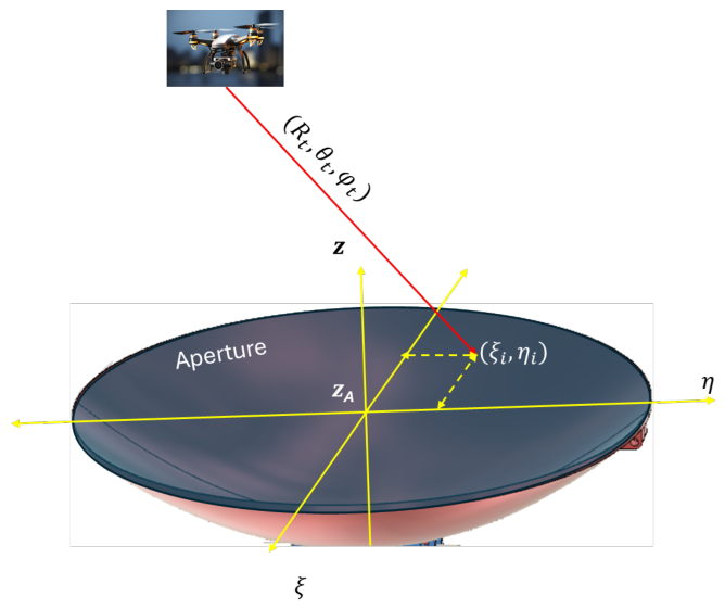
Figure 7.
Receive-mode composite waveforms generated by the Dish–SUCA architecture.
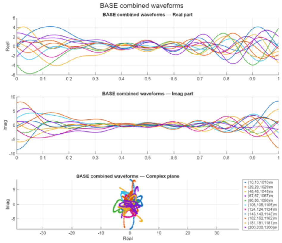
Figure 8.
Element0-normalized composite waveforms.
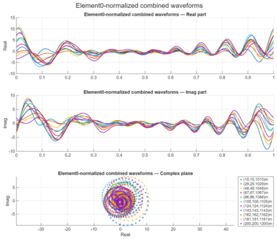
Figure 10.
Predicted received single-dwell power versus transmitter EIRP for GHz and s. The dashed line denotes the thermal-noise-limited detection threshold corresponding to dB. The intersection indicates the minimum EIRP required for reliable single-dwell detection under the assumed geometry. Target–radar range is 1 km.
Figure 10.
Predicted received single-dwell power versus transmitter EIRP for GHz and s. The dashed line denotes the thermal-noise-limited detection threshold corresponding to dB. The intersection indicates the minimum EIRP required for reliable single-dwell detection under the assumed geometry. Target–radar range is 1 km.
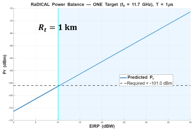
Figure 11.
Predicted received single-dwell power versus transmitter EIRP for GHz and s. The dashed line denotes the thermal-noise-limited detection threshold corresponding to dB. The intersection indicates the minimum EIRP required for reliable single-dwell detection under the assumed geometry. Target–radar range is 10 km.
Figure 11.
Predicted received single-dwell power versus transmitter EIRP for GHz and s. The dashed line denotes the thermal-noise-limited detection threshold corresponding to dB. The intersection indicates the minimum EIRP required for reliable single-dwell detection under the assumed geometry. Target–radar range is 10 km.
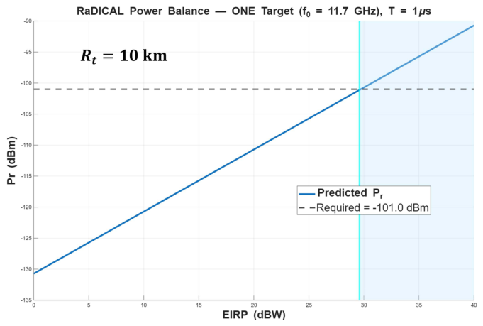
Figure 13.
Receiver operating characteristic (ROC) curves under complex white Gaussian noise for , 0, and dB.
Figure 13.
Receiver operating characteristic (ROC) curves under complex white Gaussian noise for , 0, and dB.
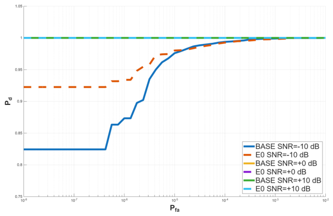
Table 2.
Parameters Used in the Numerical Simulations
| Parameter | Value |
|---|---|
| Carrier frequency | |
| Wavelength | |
| Dish diameter D | () |
| Focal ratio | 1 |
| Number of SUCA elements M | 12 (11 ring + center) |
| SUCA ring radius | |
| Ring arc spacing | () |
| SUCA axial offset from focus | () |
| Dither frequency step | |
| Dwell time | |
| Satellite–target range | |
| Target–receiver range | |
| Bistatic RCS | () |
| Starlink EIRP | 0– |
| Receiver noise figure | |
| Thermal noise (1 MHz BW, NF = 3 dB) | |
| Monte Carlo trials per SNR point | 2000 |
| Dictionary Target Grid | |
| Target grid | (11 points) |
| Target grid | (11 points) |
| Target grid | (11 points) |
| Total grid points | |
Disclaimer/Publisher’s Note: The statements, opinions and data contained in all publications are solely those of the individual author(s) and contributor(s) and not of MDPI and/or the editor(s). MDPI and/or the editor(s) disclaim responsibility for any injury to people or property resulting from any ideas, methods, instructions or products referred to in the content. |
© 2026 by the authors. Licensee MDPI, Basel, Switzerland. This article is an open access article distributed under the terms and conditions of the Creative Commons Attribution (CC BY) license (http://creativecommons.org/licenses/by/4.0/).
Copyright: This open access article is published under a Creative Commons CC BY 4.0 license, which permit the free download, distribution, and reuse, provided that the author and preprint are cited in any reuse.


