

Submitted:
01 August 2026
Posted:
03 August 2026
You are already at the latest version
Abstract
This study investigates model-based emergency strategies for damage prevention following cable breaks in six-degree-of-freedom cable-driven parallel robots. By relaxing real-time constraints, the theoretical performance ceiling of existing and novel recovery approaches is assessed through comprehensive simulations of the SEGESTA prototype. While extending prediction horizons improves recovery, it induces prohibitive computational loads. A hybrid approach combining State-of-the-Art approaches emerges as the optimal compromise, preserving high success rates while reducing calculation time and enabling active obstacle avoidance. Furthermore, a time-to-crash analyses after cable breaks demonstrates that the physical CDPR design fundamentally influences post-failure dynamics and could lead to narrow time windows for recovery approaches. Consequently, model-based emergency strategies are approaching their limits. Future research must overcome this by synergizing data-driven control paradigms with structurally fault-tolerant robot designs to ensure robust, real-time damage prevention after cable breaks.
Keywords:
cable-driven parallel robots
; cable break
; cable failure
; emergency strategy
; model-based control
; wrench-feasible workspace
; non-linear model predictive control
; fault tolerance
; safety
1. Motivation
Cable Driven Parallel Robots (CDPRs) are currently undergoing a transformation from scientific observation within the framework of publicly funded research projects to industrial applications. In addition to what is probably their best-known application as SkyCams in sports stadiums [1], the first start-ups are beginning to sell cable robots commercially [2,3]. In the context of industrial applications, the question of the safety of CDPRs is being raised [4]. A critical damage scenario is represented by a cable break [5,6]. After a cable break, the platform can still be manipulated to a limited extent using the remaining cables [4]. While several model-based emergency strategies have been proposed in the literature [5,6,7,8,9,10,11], they all face challenges regarding the strict real-time requirements of CDPR control algorithms. To meet these demands, some approaches inherently limit their operational behaviour [4]. This raises the question: How effective could emergency strategies become if real-time constraints were removed? This study investigates existing emergency strategies for 6-DoF CDPRs, develops novel approaches, and compares them through comprehensive simulations. The resulting performance plateau is further analyzed by examining the system’s behaviour and the available capabilities following a cable failure.
Existing literature offers various model-based emergency strategies aimed at reducing damage after cable breaks. For instance, dynamic trajectory planning has been utilized to bring the robot into a safe target position after cable breaks [8]. Alternatively, an algorithm was presented that guides the platform into the safte target position along a straigth line [6], a concept that has also been experimentally validated [9]. A major limitation of these techniques, however, is their restriction to spatial systems operating with only three DoF.
Consequently, the present study shifts the focus to fully constrained cable robots featuring six DoF. For such complex architectures, only two model-based emergency strategies are currently established in the State-of-the-Art [4]. The first approach relies on artificial potential fields to navigate the platform into a safe target position while actively preventing crashes with obstacles by repulsive fields. The second strategy eliminates the necessity for a predetermined target position by implementing a nonlinear model predictive control (NMPC) scheme. By strictly minimizing the system’s kinetic energy, this controller effectively decelerates the platform to a complete halt.
The study is structured as follows: Section 2 provides a comprehensive overview of the kinematics, dynamics, and cable force calculation methods for cable-driven parallel robots, including the cable force calculation beyond the wrench feasible workspace. Section 3 introduces both the established and the novel model-based emergency strategies evaluated in this study. Section 4 details the simulation setup and the performance metrics utilized to assess these recovery strategies. Additionally, the simulation results are presented. Section 5 analyzes the mechanical impact of cable breaks on the post-failure dynamics, highlighting the critical influence of the robot’s physical design on the time-to-crash. Finally, Section 6 concludes the paper with a summary of the key findings and outlines future research directions.
2. Cable Driven Parallel Robots
CDPRs are a special type of parallel robot. A mobile platform is connected to a fixed frame by cables. The position of the mobile platform can be manipulated by controlled winding and unwinding of the cables. This design offers the advantages of large workspaces – since cable lengths can be extended practically indefinitely – together with high dynamic performance enabled by decentralized drives, as well as a high payload capacity.
Cable robots are classified according to the number of cables they have [12]. This study uses so-called Redundantly Restricted Parallel Mechanisms (RRPMs). More cables m than degrees of freedom n are used. The resulting difference, , is called redundancy. The SEGESTA1 prototype analysed here has eight cables and six degrees of freedom, giving a redundancy of two.
2.1. Kinematics
To describe the cable vector , we introduce the body-fixed coordinate system attached to the mobile platform and the space-fixed coordinate system associated with the frame. The pose of the platform, denoted by , is composed of its position and orientation . The rotation matrix describes the platform’s orientation relative to the coordinate system . As can be seen in Figure 1, the cable vector is determined by the position of the platform and the positions of the cable anchor points on the platform and the frame respectively [7]. Note that the position of the cable anchor point on the platform is given in the body-fixed coordinate system , and first must be transformed into the coordinate system using the rotation matrix .
2.2. Cable Forces
Each cable applies a force to the robot’s platform. These forces act along their respective cables. Equation 1 is used to calculate the unit vector , which, together with the amount of cable force , results in the cable force vector of the cable [7]. For simplicity the index representing the body-fixed coordinate system is left out.
Together, the individual cable forces generate a so-called wrench acting on the platform, consisting of forces and torques . In general, the relationship between the cable forces and the wrench on the platform is described by the following equation using the structure matrix [7].
2.3. Dynamics
During dynamic transitions, the platform’s motion is in equilibrium with the cable forces. Incorporating the mass matrix , the centrifugal and Coriolis forces , and all remaining external wrench components (e.g., gravitational effects, friction, and disturbances, including the wrench ), the dynamic behaviour of the CDPR is defined as [7]:
2.4. Cable Force Limits
Cable robots have the drawback that cables can pull but cannot push. As a result, cable forces must stay within specific limits. A minimum force is needed to keep the cable in tension, while the cables and actuators can only generate a limited force, leading to a maximum force [16].
This inequality can be interpreted as a m-dimensional hypercube whose faces represent the cable force limits defined by [16]. Solving equation 3 yields [16]:
Due to the redundancy of the cable robot, the system in Equation 6 is underdetermined, which results in an infinite number of solutions. These can be expressed using the Moore–Penrose pseudo-inverse , the kernel of the structure matrix , and a multiplier . Equation 6 contains all solutions and therefore represents the solution space [16]. Feasible cable force distributions exist if the hypercube intersects with the solution space () [16].
2.5. Cable Force Calculation beyond the Wrench Feasible Workspace
In order to control a CDPR, one must find a cable force distribution within the solution space . This is a widespread problem in cable robotics [17]. However, in the event of a cable break, the platform may be located outside of the so-called wrench-feasible workspace () [7].
The incorporates all poses in which a desired wrench can be achieved with feasible cable force distributions. By definition, an exact calculation of the desired wrench to control the platform after a cable break is impossible outside the , as the solution space does not intersect with the hypercube of feasible cable forces (). Therefore, methods for approximating cable forces outside the are presented in the following.
Côté et al. presented a first scientific approach to approximate cable forces outside the [18]. Cable forces are estimated using quadratic programming to solve Equation 3. A discrepancy between the actual wrench and the desired wrench is permitted by introducing so-called slack variables , as shown in Equation 7.
The optimization problem is defined by minimizing the magnitude of the slack variables, thereby reducing the wrench error, while respecting the cable force limits, as shown in Equation 5.
Here, and serve as diagonal weighting matrices. Achieving an optimal approximation of the desired wrench requires the magnitudes in to dominate those in : ; . Following the options outlined by Côté et al. [18] to find , the mid-range tension is chosen to balance low power demands with enhanced platform stiffness. However, this approach is not real-time capable and continuous cable forces can not be guaranteed by the authors.
Overcoming the real-time requirements, Boumann and Bruckmann introduced the Nearest Corner Method (NCM) [19]. Beyond the no intersection between the solution space and the hypercube exists (). Based on this geometrical considerations, the algorithm evaluates the proximity of all hypercube corners () to the solution space and tries to identify the nearest corner, as shown in Figure 2a.
Let be the orthogonal projection of the corner onto . The corresponding Euclidean distance is defined as:
To prevent discontinuous force step-changes resulting from discrete corner switching during trajectory execution, a continuous, distance-based exponential weighting is applied. For each corner, an individual weight is assigned via:
denotes a positive exponential weight. Defining the cumulative weight as , the desired wrench is approximated by the weighted combination of all hypercube corners:
This method ensures that cable forces remain inside the cable force limits () and guarantees a real-time capable solution. However, while the exponential weighting ensures continuous cable forces outside the (), a fundamental discontinuity occurs during transitions across the boundary [11,19]. When the platform returns to the , the solution space and the hypercube begin to intersect (), principally allowing standard cable force calculation algorithms (e.g., the puncture method [20] as demonstrated in [19]) to take over. However, at this exact geometric boundary, the commanded cable forces exhibit an abrupt step-change as the control framework switches from approximating the desired wrench to an exact, physically valid solution.
To address this problem, the authors of this study at hand introduced the Extended Closed Form Method (ECF), a fast, real-time capable, geometric, and continuous approach [11]. Unlike the NCM, which evaluates all corners of the hypercube, the ECF projects only its geometric center point and determines the intersection between the projected line and the surface of the hypercube, as shown in Figure 2b.
The geometric center point is defined as and is projected on the solution space using the Closed Form Method (CFM, [21])
where represents the minimal distance solution between and [11].
If the CFM estimates a non-feasible solution, thus not within the hypercube , a line g is drawn between and the geometric center point :
The multiplier corresponds to the initial state , while corresponds to the exact solution by the CFM . To estimate the value of the intersection with the surface of the hypercube , all violations of the cable force limits k of each cable i are estimated:
Here, is and is . The intersection of the line g and the surface of the hypercube closest to the solutions space is identified:
Substituting Equation 15 into 13 results in the approximated cable forces . As the ECF does not have to project all corners of the hypercube , the calculation time is reduced by 93 % compared to the NCM. Additionally, the transition into the and the corresponding switch to the CFM remain continuous.
However, a limitation must be considered: since the ECF relies on the CFM, it inherits its structural constraints. Most notably, the CFM does not cover the entire . Consequently, near the workspace boundaries, this limitation leads to a less accurate estimation of the desired wrench, while another method could find an exact solution of Equation 6, presenting a trade-off between force continuity and wrench accuracy. This study also analyzes whether the benefits of continuous cable forces outweigh the loss in wrench accuracy.
3. Model Based Emergency Strategies
Cable breaks are a well-known problem with CDPRs in the literature [5,6,7,8,9,10,11]. To the best authors knowledge, for CDPRs with six degrees of freedom, only three approaches are currently known [22], of which only two are model-based. The following section presents the algorithms currently known in the literature (Section 3.1), along with novel approaches (Section 3.2).
3.1. State of the Art
As previously noted, only two model-based approaches are established in the literature. For a comprehensive comparison, both strategies are evaluated within the simulation framework as well.
3.1.1. Energy Minimization Method
First, the Energy Minimization Method (EMM), initially proposed by Boumann and Bruckmann [5] and extended by Boumann [4], is examined. The method aims to reduce the platforms kinetic energy using a non-linear model predictive controller. Model predictive controllers predict the behaviour of the system for given control inputs based on mathematical models [23]. In this context, the control inputs are the cable forces. An iterative optimization algorithm adjusts these inputs at each control step to minimize a cost function [23]. Due to the iterative approach, it is difficult to guarantee real-time capability for this approach. To ensure real-time capability and satisfy the required control frequency, the maximum number of iterative steps is set to 50 with a prediction horizon of only one step [4].
The mathematical equations describing the dynamics of the cable robot are given in Equation 4. To predict the systems behaviour, this equation is solved for the acceleration [4].
Integrating the acceleration yields the velocity, and a second integration provides the platform pose, which is subsequently used to compute the future time steps. The number of steps considered ahead in time are defined by the control horizon and the prediction horizon . The control horizon specifies the steps over which control inputs are optimized. Beyond this horizon, the control input is assumed to remain constant. The prediction horizon may exceed the control horizon (). Up to this point, the dynamic behaviour of the robot is predicted. Following the approach in [23] for non-linear model predictive control, the control and prediction horizons are chosen to be identical (). To optimize the control inputs, the results of the dynamic prediction are incorporated into a cost function for each time step k. Boumann uses platform velocities to reduce kinetic energy and changes in cable forces, thereby minimising jerk and, consequently, oscillations [5]. The velocities are weighted by a weighting matrix , while the change in force is weighted by a weighting matrix .
The optimization problem for the EMM is formulated as [4]:
3.1.2. Potential Field Method
The second approach, also initially presented by Boumann and Bruckmann [5] and extended by Boumann [4], follows a standard method from robot path planning [24]. In the so-called potential field method (PFM), virtual forces are generated by artificial potential fields. Repulsive fields associated with obstacles and the ground prevent collisions, while an attractive field guides the platform toward its target position. In addition, virtual damping is added to the forces generated by the potential field method [4].
The attractive forces , torques , and all i-th repulsive forces are combined into the wrench of external forces . The remaining external forces and torques , as well as the virtual damping, are also included. The scaling of the virtual damping is performed using two diagonal matrices: for translational velocities and for rotational velocities. The resulting wrench of external forces obtained using the potential field method yields [4]:
To control the robot accordingly, the generated wrench must be converted into cable forces, which requires specialized distribution methods as introduced in Section 2.5. Currently, the NCM represents the State-of-the-Art approach for this task. In the remainder of this work, this combined strategy is referred to as PFM-NCM.
3.2. Novel Approaches
In addition to the simulation analysis of known strategies for damage prevention after cable breaks, this study also presents novel approaches.
3.2.1. Energy Minimization Method with Extended Prediction and Control Horizon
A central objective of this research is evaluating the performance gains achieved by removing real-time constraints. Consequently, the first step investigates the impact of extending the EMM prediction and control horizon. For this purpose, the horizon is incrementally raised from one to five (). A comprehensive analysis on the influence of the prediction and control horizon is conduceted in Section 4.2.
3.2.2. Potential Field Method with Extended Closed Form Method
The Potential Field Method, described in Section 3.1.2, generates a virtual wrench at the robot’s platform through a combination of attractive and repulsive fields, with the baseline cable forces computed via the NCM. Conversely, the ECF aims to enhance stability through continuous cable force calculation. In addition to the State-of-the-Art solution utilizing the NCM, this study investigates the performance of the ECF when integrated with the potential field method, referred to as PFM-ECF.
3.2.3. Energy Minimization Method with Extended Closed Form Method
Compared to the NCM, the ECF exhibits two primary distinctions: it guarantees continuous force trajectories and significantly reduces computational time. With an average execution time of [11] within an available time window of , the ECF can be integrated into iterative optimization loops, such as a NMPC. The EMM utilizes the NMPC for two core tasks: path planning and cable force distribution. If the optimization vector of the NMPC is limited to the platform wrench, the task reduces to path planning, while the cable forces are calculated by the ECF. Evaluated with a prediction and control horizon of , this combined strategy is referred to as EMM-ECF in the remainder of this study. Consequently, the optimization problem is defined using the ECF algorithm while retaining the cost function from Equation 17:
3.2.4. Combination of the Energy Minimization Method and Potential Field Method
Additionally, both State-of-the-Art approaches are combined to synergize their respective advantages. The combination of a NMPC with a potential field method is known, for example, from vessel path planning [25]: In this instance, the direction of the resulting force vectors from the potential field method is compared with the current vehicle direction. The objective of the NMPC is to optimise the control variables so that the vessel follows the force direction of the NMPC. In order to transfer this approach to cable robotics, the wrench of the potential field method is compared with the actual wrench from the applied cable forces. Thus, the NMPC is used to implement the desired wrench of the potential field method through an optimisation algorithm. The cost function is updated:
The objective function is minimized with respect to the cable forces , subject to the desired wrench from the potential field method in Equation 19, the resulting equilibrium between the cable forces and the actual wrench according to Equation 3 and the cable force limits. The optimization objective of minimizing the kinetic energy inherently eliminates the need for virtual damping within the Potential Field method.
This approach is simulated and evaluated using a prediction and control horizon of and referred to as EMM-PFM.
4. Simulation
This chapter presents a simulation-based evaluation implemented in MATLAB® Simulink® (MathWorks) to assess the described emergency strategies following cable breaks. Robustness and generality are assessed through 1000 simulations with randomly distributed initial conditions within the static equilibrium constant orientation workspace () prior to a cable break. All simulations are performed using the multibody simulation model proposed by Boumann [4], which represents the 6-DOF cable-driven parallel robot SEGESTA with eight cables. The model includes actuator dynamics, platform inertia, and cable elasticity, alongside a detailed representation of pulley and winch kinematics. All parameters describing these effects were determined via measurements on the physical SEGESTA prototype or obtained from data sheets. The real robot control architecture is extended by the described methods, operating at a control frequency of , while the underlying dynamic model is evaluated at . The most relevant parameters are shown in Table 1.
4.1. Evaluation Method
For a methodical evaluation and a comprehensive comparison of the described approaches, several performance metrics are defined. The primary metric is the success rate across all simulation runs for each method. A simulation run is considered successful if it runs for after the cable break without a platform crash. A crash is defined as a platform tilt exceeding about any of its axes. Such extreme rotations typically lead to cable-cable collisions, causing the cables to entangle and resulting in a total loss of platform control. The SR is defined as the proportion of successful runs :
Furthermore, the computational time of each control step is measured directly within the Simulink environment. The mean computational time is determined by the average time of each control cycle and across all simulation runs .
Additionally, an emergency strategy with a high SR but server impact damages in crash scenarios would remain unfeasible. Therefore, the velocities and thus the resulting platforms kinetic energy at the moment of impact are tracked and compared.
4.2. Influence of the Prediction and Control Horizon
This study investigates the performance of various model-based emergency strategies following cable breaks by relaxing strict real-time requirements within the simulation environment. To meet real-time requirements, the EMM with NMPC by Boumann [4] was restricted to a prediction and control horizon of . However, the full advantages of an NMPC arise from predictive control planning, which allows the algorithm to bypass local minima within the cost function optimization. Simulation offers the distinct advantage that these stringent real-time constraints can be relaxed. Therefore, multiple simulation runs were conducted, incrementally increasing the prediction and control horizon from to . The simulation results demonstrating the influence of the prediction and control horizon length n on the SR and mean computational time for the EMM based on [5] are illustrated in Figure 3a. The corresponding crash velocities and resulting kinetic energy are shown in Figure 3b.
As shown, increasing the horizon step-by-step from to yields an overall improvement in the SR. This positive correlation is emphasized by the linear trendline, indicating that a longer look-ahead horizon allows the optimization framework to anticipate system dynamics and post-break constraints more effectively. However, the SR does not scale strictly monotonically, as a minor drop is observed at compared to , before continuing its upward trend.
Concurrently, extending the horizon inherently increases the computational overhead. While the mean computational time remains remarkably low for a short horizon, it grows progressively with larger values of n, showing a significant, non-linear growth. Due to this substantial increase in computational cost, longer horizons are not evaluated, as the simulation turnaround times scale impractical.
The statistical distribution of the kinetic energy at the moment of impact across the different horizon lengths is illustrated in the boxplot in Figure 3b. Extending the prediction and control horizon from to shows no significant impact on the severity of the remaining platform crashes. Across all evaluated horizons, both the median crash energy and the overall spread of the data points remain consistent.
This investigation indicates that while a longer look-ahead horizon successfully increases the overall SR by preventing a larger portion of failures, it does not mitigate the destructive energy or kinematics of scenarios where control is inevitably lost. Additionally, the marginal increase in the SR of approximately 3.5 % comes at the cost of expanding the mean computational time by a factor of nearly 280. Note that, following Eq. 25, a crash energy of corresponds to a purely translational velocity of , whereas a purely rotational breakdown would result in an angular velocity of . This highlights the platform’s instability regarding rotational motion and provides an explanation as to why the predominant cause of a crash following a cable break is an uncontrolled rotation about one of its axes. The resulting cable-cable collisions inevitably lead to a total loss of platform control.
Since increasing the prediction and control horizon led to a higher SR, the two extrema and are defined for the NMPC-based strategies, referred to as EMM-H1 and EMM-H5, respectively. To evaluate maximum performance, all subsequent investigations incorporating an NMPC will focus on the horizon .
4.3. Comparative Evaluation of Model-Based Cable Break Recovery Strategies
Apart from the analysis regarding the influence of the prediction and control horizon, this study evaluates all presented emergency strategies. The simulation results for each method, including the SR and mean computational time, are depicted in Figure 4. Analogous to the findings in Figure 3b, the analysis of the crash kinetic energy revealed no significant variation across the different strategies and is therefore omitted.
First, comparing EMM-H1 and EMM-H5, increasing the prediction and control horizon yields a minor improvement in the overall SR, whereas the computational time increases substantially for the latter (as descriped in Section 4.2).
Second, the potential field methods exhibit slightly lower SRs than the EMM strategies but offer significantly reduced computational times. This observation confirms the findings of Boumann [4].
The ECF serves as a novel cable force calculation algorithm designed to approximate a desired wrench outside the . While it reduces computational time and guarantees continuous cable force trajectories, this efficiency comes at the expense of approximation accuracy. The simulation results indicate that precise wrench approximation appears to be more critical for platform recovery than cable force trajectory continuity, given that the PFM-NCM yields better results than the PFM-ECF. However, the PFM-ECF substantially lowers the mean calculation time.
Overall, both PFM variants constitute fully real-time-capable emergency strategies. They are the only investigated methods that unconditionally satisfy the real-time requirements of the robotic system.
Third, the high computational efficiency of the ECF is leveraged to reduce the overall calculation time of the EMM in the EMM-ECF. To achieve this, the underlying optimization problem is simplified, and the ECF is directly employed for the cable force distribution. The results demonstrate a significant reduction in computational time by . However, this improved efficiency comes at the expense of the SR, which decreases to compared to the EMM-H5 (). Nevertheless, applying Bayesian optimization to fine-tune the internal parameters of this combined method could further enhance its performance in future research.
Fourth, the EMM incorporating the NMPC is combined with the PFM. This strategy aims to merge the collision avoidance capabilities of the PFM with the higher SR associated with the EMM. The combined approach is evaluated using a prediction and control horizon of .
The simulation results demonstrate that the SR of the EMM-PFM () is only marginally lower than that of the EMM-H5 (). It should be noted, however, that while 1,000 simulation runs constitute a substantial sample size, a certain statistical variance relative to the true, unmeasurable SR remains, which would require an infinite amount of simulations. Therefore, this minor discrepancy may simply be attributed to the specific set of initial conditions randomly sampled for the evaluations.
In summary, combining the two State-of-the-Art approaches yields a comparable SR while simultaneously reducing the computational time by of EMM-PFM with respect to the EMM-H5. Furthermore, incorporating the PFM enables the method to actively evade defined obstacles—an intrinsic capability of the PFM that has been previously validated by Boumann [4]. While this combined strategy currently falls short of strict real-time requirements, it represents a highly promising framework for future applications. To bridge this gap and achieve real-time capability, future implementations could integrate machine learning techniques [22] or reinforcement learning strategies [26].
In conclusion, choosing an emergency strategy involves making a fundamental trade-off between computational efficiency and the SR. While the pure PFM variants currently remain the only unconditionally real-time-capable solutions, the hybrid EMM-PFM framework emerges as the most comprehensive compromise. By preserving the high SR of the EMM and integrating the obstacle avoidance capabilities of the PFM, it reduces computational costs without sacrificing robustness. However, the results also indicate a performance plateau regarding the maximum achievable SR, a phenomenon that will be investigated in detail in the Section 5.
5. Mechanical Impact of the Missing Cable
The simulation results of this study indicate a performance plateau regarding the SR of the evaluated emergency strategies. To gain a deeper understanding of the moving platform’s dynamics following a cable break, a brief analytical investigation is conducted. For this purpose, the mechanical impact of the missing cable is analyzed in detail.
A cable break can occur at any arbitrary operational state of the robot. Immediately prior to the failure, the applied cable force distribution yields a resulting platform wrench that controls the system’s motion (e.g. acceleration, deceleration, movement at a constant velocity, or maintenance of static equilibrium). If a cable breaks, the corresponding cable force will be suddenly removed from the cable force distribution. Due to dead time in signal transmission, drive inertia, and cable dynamics, any control algorithm will be unable to apply force changes to the platform instantaneously. Since the cable force distribution just prior to the cable break carries over at the moment of the break, the platform is subjected to an initial (possibly suboptimal) wrench . To calculate this wrench, the contributions of the broken cable to both the structure matrix and the cable force vector are omitted from Equation 4. The remaining terms define the post-failure structure matrix and the corresponding force distribution . Let k denote the failed cable. For simplicity, let .
Therefore, the post-failure wrench can also be determined from the pre-failure wrench of the broken cable using Equation 26:
When cable k breaks, its force satisfies , so the k-th wrench contribution vanishes. Consequently, the static equilibrium of Equation 26 is disrupted. Combined with Equation 4, this yields:
Assuming a constant post-failure wrench , the time-to-crash can be estimated by integrating Equation 28 until the platform tilts more then around any of it’s axis. At this point cable-cable collisions would already occur, thus leading to a total loss of control of the platform.
Using this procedure, the entire of the reference prototype SEGESTA is analyzed. Specifically, configurations with an upright orientation (roll, pitch, yaw ) were sampled within the pre-failure workspace. The results for SEGESTA are shown in Figure 5a. The data shows that the platform crashes increasingly quickly the closer the platform lies to the broken cable, hence the farther away from the post-failure workspace. At a control rate of (), this leaves only a few control cycles and poses a significant challenge for emergency strategies. This provides a possible explanation for why these strategies struggle to recover the platform when a cable break occurs at greater distances from the post-failure workspace, and why the overall SR plateaus independently of the implemented recovery method.
Note that the upper and lower cables of the SEGESTA are crossed. Additionally, two lower cables share the same anchor point on the upper side of the platform, as depicted in Figure 6. This configuration is typically chosen to enhance stiffness and enlarge the workspace of the CDPR [12]. To evaluate the impact of this design, a secondary analysis assumes a simplified box-shaped platform. In this theoretical setup, one cable is attached to each corner of the platform and routed directly to the corresponding corner of the frame, yielding a newly defined set of platform anchor points .
As illustrated in Figure 5b, this simplified uncrossed configuration results in significantly longer time-to-crash intervals. Consequently, the findings indicate that CDPR design paradigms must be critically re-evaluated. A careful balance is required between maximizing system stiffness and mitigating the risk of unrecoverable cable failure incidents.
6. Conclusions
This study presents a comprehensive simulative investigation of model-based emergency strategies for damage prevention following cable breaks in 6-DoF CDPRs. By relaxing strict real-time constraints, a performance plateau is identified: the maximum achievable recovery rate across all tested methods peaks at approximately , as observed in the EMM-H5 and EMM-PFM approaches.
The analysis highlights a fundamental trade-off in optimization-based controllers. Increasing the NMPCs prediction horizon from to yields a increase in SR but causes a rapid rise in computational time, rendering it impractical for real-time execution. Among the evaluated strategies, the hybrid EMM-PFM framework emerges as the optimal compromise. It achieves a comparable SR of while reducing computational time by and integrating active obstacle avoidance. Nevertheless, it still falls short of the real-time requirements of the CDPR.
Furthermore, the physical CDPR design influences post-failure dynamics and provides a direct explanation for the observed performance plateau. The time-to-crash analysis reveals that the robot’s geometry inherently dictates extremely narrow time windows for recovery before unrecoverable geometric cable cable collisions occur. For instance, a simplified uncrossed cable configuration significantly reduces these already critical time-to-crash intervals compared to the crossed design of the SEGESTA prototype.
To summarize, current model-based strategies seem to approach an upper limit in SR, possible constrained by the physical geometry of the system. To overcome this performance plateau and achieve real-time capability, future research must employ a dual approach, considering both advanced, potentially data-driven control algorithms and structural robot redesign. Reinforcement learning holds the potential to discover novel, situation-dependent recovery behaviors through trial-and-error exploration. Concurrently, future CDPR architectures must be inherently designed for fault tolerance. By optimizing anchor point configurations, the critical time-to-crash windows can be widened to prevent unrecoverable geometric cable-cable collisions after cable breaks. Only by synergizing intelligent, learning-based control frameworks with resilient physical designs the boundaries of damage prevention in CDPRs can be pushed beyond current limitations.
Funding
The work on this paper is funded by the Deutsche Forschungsgemeinschaft (DFG, German Research Foundation) – Projektnummer 506498608
Data Availability Statement
The simulation model and datasets used, generated and analyzed during this study are not publicly available due to a Non-Disclosure Agreement (NDA).
Acknowledgments
During the preparation of this manuscript, the authors used Google Gemini (Personal AI Collaborator) for the purposes of text revision. The authors have reviewed and edited the output and take full responsibility for the content of this publication.
Abbreviations
The following abbreviations are used in this manuscript:
| CDPR | Cable Driven Parallel Robots |
| CFM | Closed Form Method |
| DoF | Degree of freedom |
| ECF | Extended Closed Form Method |
| EMM | Energy Minimization Method |
| EMM-ECF | Energy Minimization Method with Extended Closed Form Method |
| EMM-H1 | Energy Minimization Method with |
| EMM-H5 | Energy Minimization Method with |
| EMM-PFM | Combination of the Energy Minimization Method and Potential Field Method |
| NCM | Nearest Corner Method |
| NMPC | Non-linear Model Predictive Control |
| PFM | Potential Field Method |
| PFM-ECF | Potential Field Method with Extended Closed Form Method |
| PFM-NCM | Potential Field Method with Nearest Corner Method |
| RRPM | Redundantly Restricted Parallel Mechanisms |
| Static Equilibriums Constant Orientation Workspace | |
| SR | Success rate |
| Wrench Feasible Workspace |
References
- Brown, Garrett W. Suspension system for supporting and conveying equipment, such as a camera. US-Patent. US4710819A, 1987. [Google Scholar]
- GUIDE – Center for Entrepreneurship and Innopreneurship; University of Duisburg-Essen. red cable robots, 2024. Available online: https://www.uni-due.de/guide/team_redcablerobots.php (accessed on 2025-12-01).
- Seddon, J. Fanuc robot sparkles in new food factory cleaning solution. Machinery Market. 2025. Available online: https://www.machinery-market.co.uk/news/40329/Fanuc-robot-sparkles-in-new-food-factory-cleaning-solution (accessed on 2025-12-01).
- Boumann, R. Damage Prevention After Cable Failure in Redundant Parallel Cable Robots. In Dissertation; Universtität Duisburg-Essen: Duisburg, 2024. [Google Scholar] [CrossRef] [PubMed]
- Boumann, R.; Bruckmann, T. Development of Emergency Strategies for Cable-Driven Parallel Robots after a Cable Break. In Cable-Driven Parallel Robots;Mechanisms and Machine Science; Pott, A., Bruckmann, T., Eds.; Springer International Publishing: Cham, 2019; Vol. 74, pp. 269–280. [Google Scholar] [CrossRef]
- Boschetti, G.; Passarini, C.; Trevisani, A. A Recovery Approach for Spatial Cable Robots After Cable Failure. In Proceedings of the Advances in Italian Mechanism Science; Carbone, G., Gasparetto, A., Eds.; Cham, 2019; pp. 457–464. [Google Scholar] [CrossRef]
- Boumann, R.; Bruckmann, T. Simulation and Model-Based Verification of an Emergency Strategy for Cable Failure in Cable Robots. Actuators 2022, 11 PII, 56 act11020056. [Google Scholar] [CrossRef]
- Passarini, C.; Zanotto, D.; Boschetti, G. Dynamic Trajectory Planning for Failure Recovery in Cable-Suspended Camera Systems. J. Mech. Robot. 2019, 11. [Google Scholar] [CrossRef]
- Boschetti, G.; Minto, R.; Trevisani, A. Experimental Investigation of a Cable Robot Recovery Strategy. Robotics 2021, 10 PII, 35 robotics10010035. [Google Scholar] [CrossRef]
- Roberts, R.G.; Graham, T.; Lippitt, T. On the inverse kinematics, statics, and fault tolerance of cable-suspended robots. J. Robot. Syst. 1998, 15, 581–597. [Google Scholar]
- Gust, P.; Bruckmann, T. Cable Force Calculation Beyond the Wrench-Feasible Workspace by Extending the Closed Form Method. In Proceedings of the Cable-Driven Parallel Robots; Lau, Darwin, Pott, Andreas, Bruckmann, Tobias, Eds.; Cham, 2025; pp. 43–54. [Google Scholar] [CrossRef]
- Pott, A. Cable-Driven Parallel Robots; Springer Cham, 2018; Vol. 120. [Google Scholar] [CrossRef]
- Verhoeven, R. Analysis of the Workspace of Tendon-based Stewart Platforms. In Dissertation; Universtität Duisburg-Essen: Duisburg; URN, 2004; Available online: https://nbn-resolving.org/urn:nbn:de:hbz:464-20061017-114435-6.
- Reichert, C.; Unterberg, U.; Bruckmann, T. Energie-optimale Trajektorien für seilbasierte Manipulatoren unter Verwendung von passiven Elementen. [CrossRef] [PubMed]
- Boumann, R.; Jeziorek, C.; Bruckmann, T. Validation of Emergency Strategies for Cable-Driven Parallel Robots After a Cable Failure. Cable-Driven Parallel Robots Proceedings of the 6th International Conference on Cable-Driven Parallel Robots Vol. 132, 209–220. [CrossRef]
- Mikelsons, L.; Bruckmann, T.; Hiller, M.; Schramm, D. A real-time capable force calculation algorithm for redundant tendon-based parallel manipulators. In Proceedings of the 2008 IEEE International Conference on Robotics and Automation; IEEE, 2008; pp. 3869–3874. [Google Scholar] [CrossRef]
- Bruckmann, T. Auslegung und Betrieb redundanter paralleler Seilroboter. Dissertation, Universtität Duisburg-Essen, Duisburg, URN, 2010. Available online: https://nbn-resolving.org/urn:nbn:de:hbz:464-20101020-073248-8.
- Côté, A.F.; Cardou, P.; Gosselin, C. A tension distribution algorithm for cable-driven parallel robots operating beyond their wrench-feasible workspace. In Proceedings of the 2016 16th International Conference on Control, Automation and Systems (ICCAS), 2016; pp. 68–73. [Google Scholar] [CrossRef]
- Boumann, R.; Bruckmann, T. Real-Time Cable Force Calculation beyond the Wrench-Feasible Workspace. Robotics 2020, 9, 41. [Google Scholar] [CrossRef]
- Müller, K.; Reichert, C.; Bruckmann, T. Analysis of a Real-Time Capable Cable Force Computation Method. In Proceedings of the Cable-Driven Parallel Robots; Pott, Andreas, Bruckmann, Tobias, Eds.; Cham, 2015; pp. 227–238. [Google Scholar] [CrossRef]
- Pott, A.; Bruckmann, T.; Mikelsons, L. Closed-form Force Distribution for Parallel Wire Robots. In Proceedings of the Computational Kinematics; Kecskeméthy, Andrés, Müller, Andreas, Eds.; Berlin, Heidelberg, 2009; pp. 25–34. [Google Scholar] [CrossRef]
- Gust, P.; Hürten, C.; Boumann, R.; Bruckmann, T. Methoden des maschinellen Lernens als Notfallstrategie nach Seilrissen bei parallelen Seilrobotern. 10. IFToMM D-A-CH Konferenz, Universität Rostock, 5./6. März 2024; 2024. [Google Scholar] [CrossRef]
- Adamy, J. Nichtlineare Systeme und Regelungen, 3, aktualisierte auflage ed.; SpringerLink Bücher, Springer Vieweg: Berlin and Heidelberg, 2018. [Google Scholar] [CrossRef]
- Spong, M.W.; Hutchinson, S.; Vidyasagar, M. Robot Modeling and Control (2nd Edition), second edition ed.; John Wiley & Sons: Newark, 2020. [Google Scholar]
- Menges, D.; Tengesdal, T.; Rasheed, A. Nonlinear Model Predictive Control for Enhanced Navigation of Autonomous Surface Vessels. IFAC-PapersOnLine 2024, 58, 296–302. [Google Scholar] [CrossRef]
- Gust, P.; Heckes, H.; Bruckmann, T. A Recovery Approach for Cable-Driven Parallel Robots After Cable Breaks Based on Reinforcement Learning. In Robotics and Mechatronics;Mechanisms and Machine Science; Nguyen, V.L., Nguyen, P.D., Quang Hoang, N., Carbone, G., Eds.; Springer Nature Switzerland: Cham, 2027; Vol. 213, pp. 333–342. [Google Scholar] [CrossRef]
| 1 |
Figure 1.
A geometric model of a cable robot, based on [7]
Figure 1.
A geometric model of a cable robot, based on [7]
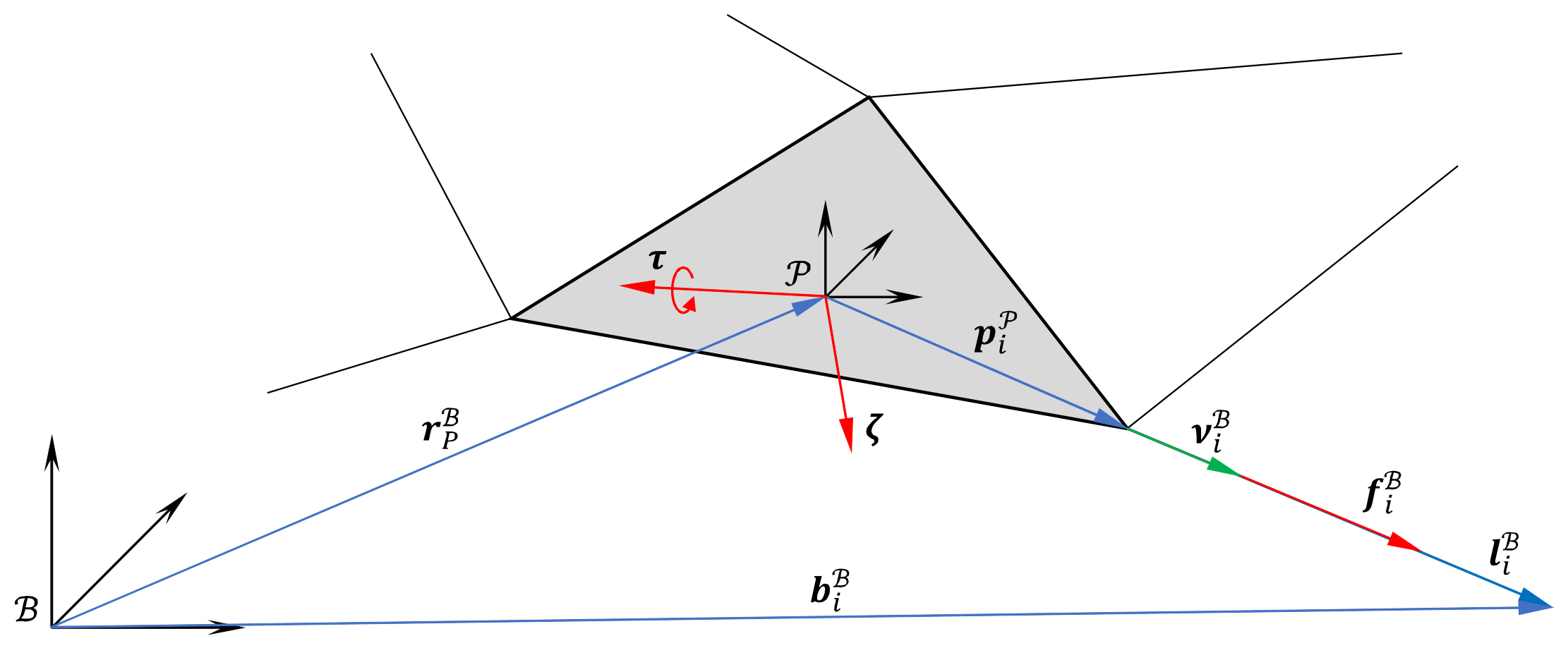
Figure 2.
Visualization of geometric cable force calculation beyond the wrench feasible workspace
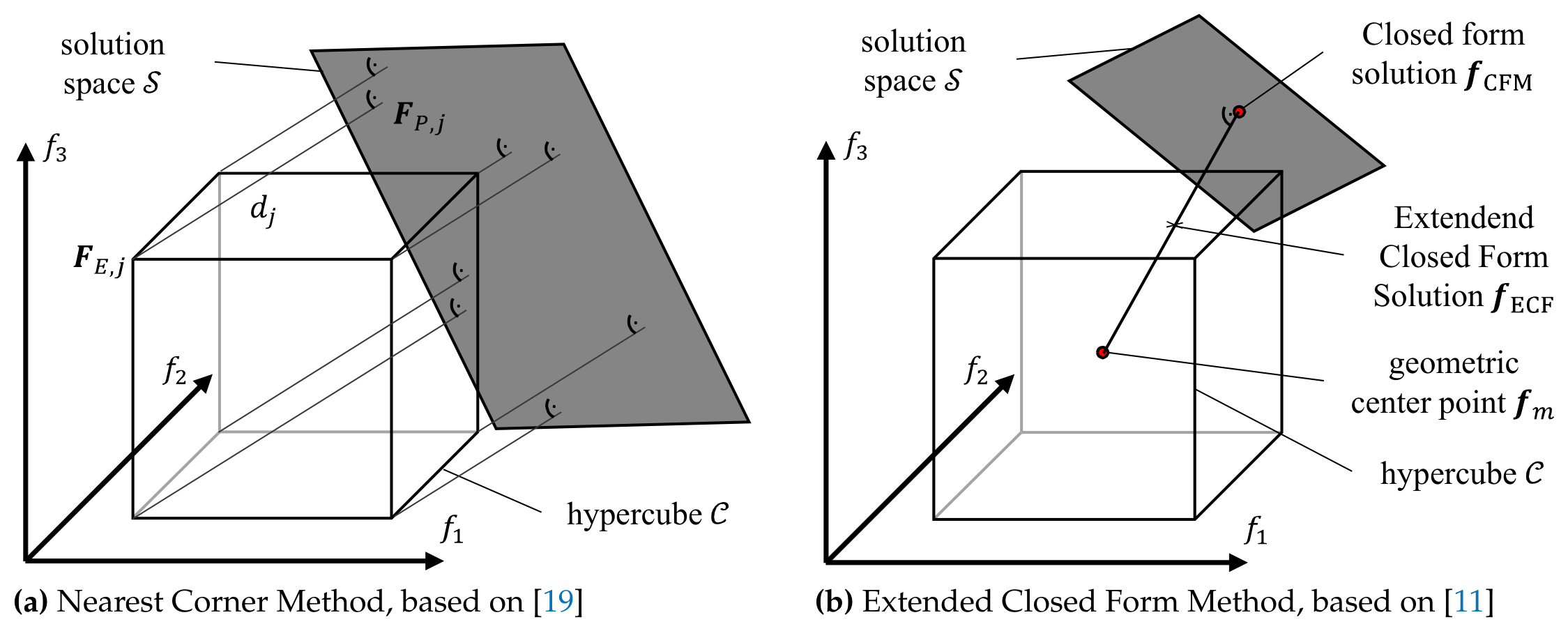
Figure 3.
Simulation results regarding the influence of the prediction and control horizon on the EMM
Figure 3.
Simulation results regarding the influence of the prediction and control horizon on the EMM
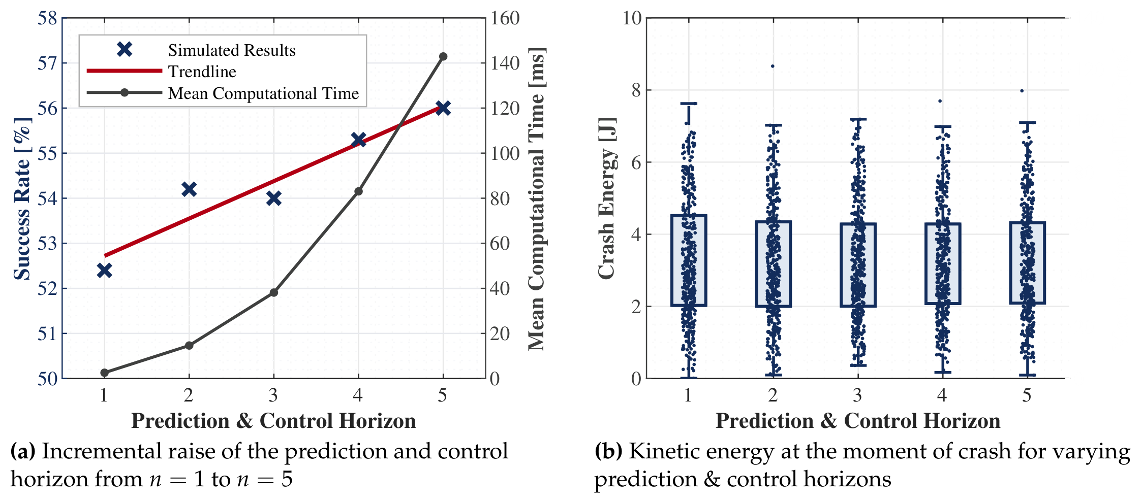
Figure 4.
Simulation results; Successfull simulations indicating the success rate on the left and the mean calculation time on the right; Dotted line representing the real-time requirements of CDPRs used within the Chair of Mechatronics.
Figure 4.
Simulation results; Successfull simulations indicating the success rate on the left and the mean calculation time on the right; Dotted line representing the real-time requirements of CDPRs used within the Chair of Mechatronics.
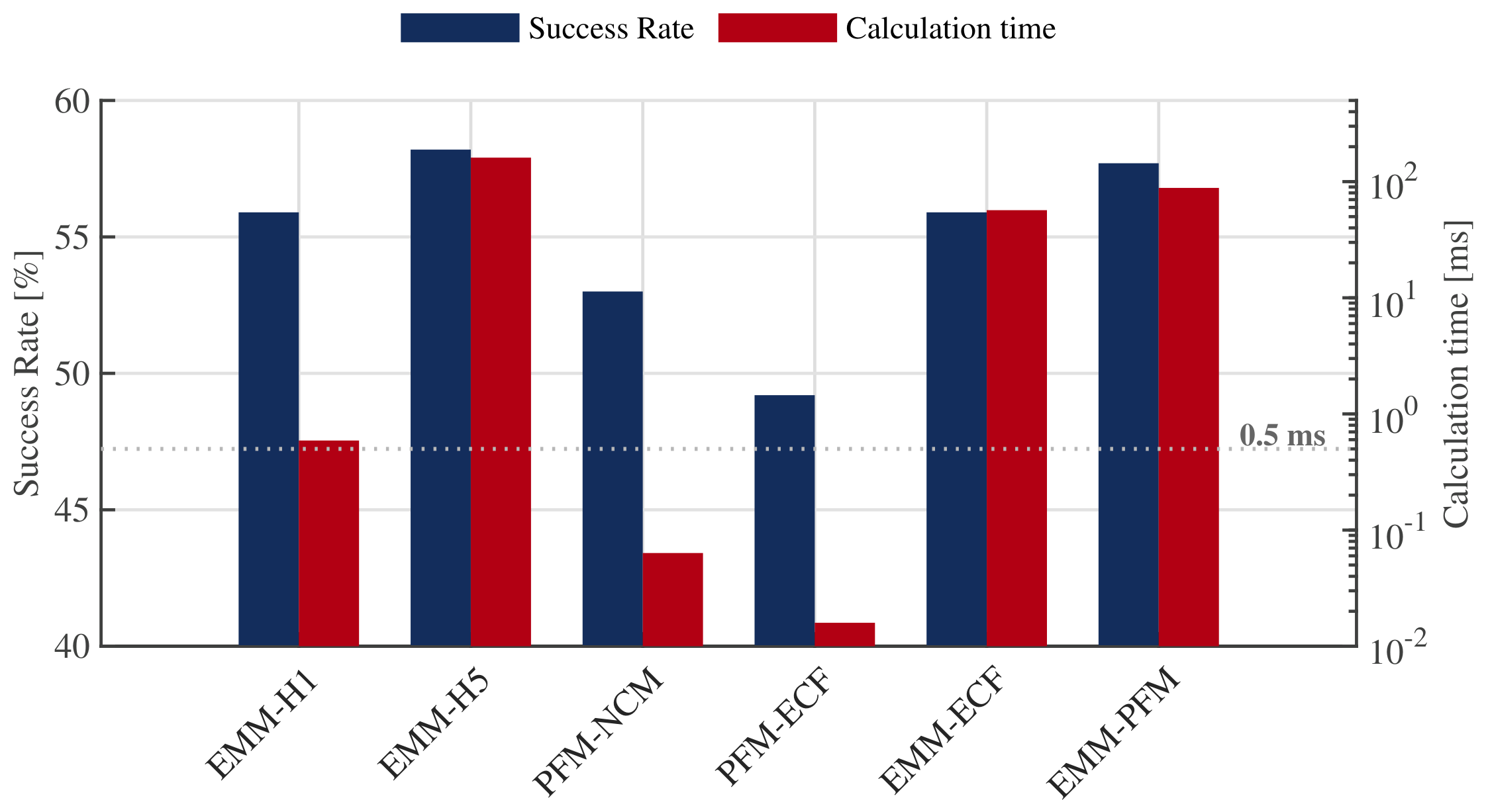
Figure 5.
Time-to-crash analysis of different robot designs
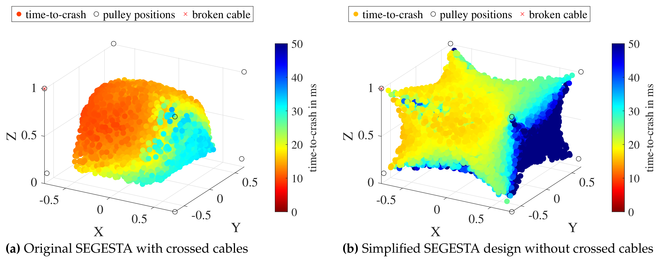
Figure 6.
Mobile platform of the SEGESTA prototype located at the Chair of Mechatronics, University of Duisburg-Essen; Equipped with a cable decoupling device at the red cable [15]
Figure 6.
Mobile platform of the SEGESTA prototype located at the Chair of Mechatronics, University of Duisburg-Essen; Equipped with a cable decoupling device at the red cable [15]
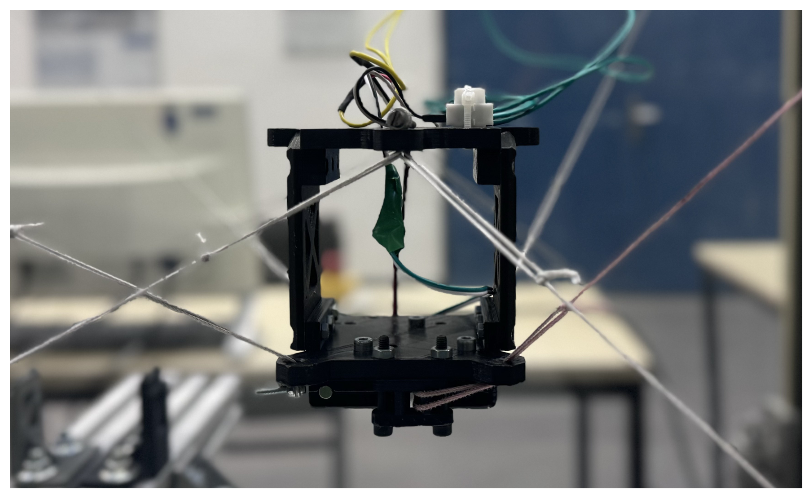

Table 1.
System parameters of the SEGESTA prototype
| Symbol | Description | Value / Matrix | Unit |
|---|---|---|---|
| Pulley position matrix | m | ||
| Platform anchor point matrix | mm | ||
| Inertia tensor | kg | ||
| Platform mass | kg | ||
| Cable force limits | N |
Disclaimer/Publisher’s Note: The statements, opinions and data contained in all publications are solely those of the individual author(s) and contributor(s) and not of MDPI and/or the editor(s). MDPI and/or the editor(s) disclaim responsibility for any injury to people or property resulting from any ideas, methods, instructions or products referred to in the content. |
© 2026 by the authors. Licensee MDPI, Basel, Switzerland. This article is an open access article distributed under the terms and conditions of the Creative Commons Attribution (CC BY) license (http://creativecommons.org/licenses/by/4.0/).
Copyright: This open access article is published under a Creative Commons CC BY 4.0 license, which permit the free download, distribution, and reuse, provided that the author and preprint are cited in any reuse.


