

Submitted:
27 July 2026
Posted:
30 July 2026
You are already at the latest version
Abstract
Accurate three-dimensional digitization of cultural stone surfaces is essential for the documentation, conservation, and quantitative assessment of architectural and archaeological heritage. Although commercial laser scanning systems provide high measurement accuracy, their cost, limited portability, and dependence on external power supplies often limit their use in many practical applications. This work presents the design, implementation, and experimental validation of a low-cost, portable laser triangulation scanner for the autonomous digitization of small- and medium-sized stone surfaces. The system integrates a lightweight motorized positioning platform, interchangeable laser line sensors, embedded motion control, wireless communication, and dedicated acquisition and visualization software into a compact device. Static calibration demonstrated high measurement accuracy along both the vertical and horizontal directions, while experimental validation under controlled laboratory conditions confirmed the capability of the system to reconstruct complex surface topographies and to determine areal roughness parameters in accordance with ISO 25178. The scanner successfully digitized granite specimens with different surface finishes, preserving fine morphological features relevant to quantitative surface characterization. The proposed system provides a reliable and cost-effective alternative to conventional scanning solutions and constitutes a versatile platform for the digital documentation, monitoring, and quantitative characterization of cultural stone surfaces, with potential applications in a broad range of non-contact surface metrology tasks.
Keywords:
laser triangulation
; portable laser scanner
; three-dimensional digitization
; surface topography
; areal roughness
; cultural stone heritage
; non-contact metrology
1. Introduction
The conservation of cultural heritage has attracted increasing attention from both the scientific community and society over recent decades. This growing interest reflects a broader recognition of the historical, artistic, and social value of heritage assets, as well as the need to preserve them for future generations. Nevertheless, many heritage objects remain vulnerable to deterioration processes that threaten their integrity and long-term preservation. Among these assets, stone-built heritage, including monuments, historical buildings, sculptures, reliefs, and archaeological remains, occupies a prominent place due to its abundance and cultural significance.
In the field of heritage conservation, the term cultural stone is commonly used to refer to stone materials that have been intentionally modified by humans through quarrying, carving, dressing, engraving, or other forms of workmanship [1].
Among the different forms of cultural stone, ashlar masonry is particularly significant due to its widespread use in historic architecture and its combination of structural and aesthetic functions. The surfaces of historic ashlars preserve a wide range of features resulting from quarrying, carving, construction processes, weathering, conservation interventions, and human activity. Among these features, tool marks are of particular interest, as they provide valuable information on historical stone-working techniques, construction phases, and, in some cases, the identification of individual craftsmen. Consequently, their study can contribute significantly to the reconstruction of the historical context and building history of monuments [2,3,4,5,6,7,8,9].
In parallel, stone degradation is a complex phenomenon driven by the interaction of physical, chemical, and biological processes, whose effects depend on both the intrinsic characteristics of the stone and the environmental conditions to which it is exposed. Surface topography and roughness are therefore relevant aspects in the characterization and conservation of stone heritage, as they can provide quantitative information on surface alterations resulting from weathering processes or conservation interventions. Roughness measurements can be used to assess deterioration, evaluate the potential impact of cleaning and other conservation treatments, and monitor surface evolution over time [10,11]. Furthermore, surface topography influences several functional properties of stone materials, including wettability, water retention, particle deposition, biological colonization, and the interaction with protective or consolidating treatments [12,13,14,15,16]. A comprehensive three-dimensional characterization of stone surfaces can therefore provide valuable information for the assessment of their state of conservation and the planning, monitoring, and evaluation of conservation interventions [17].
Whether the objective is the study of historical surface features or the assessment of stone deterioration and conservation treatments, the acquisition and preservation of detailed surface information require accurate, reproducible, and non-destructive documentation methods. Effective conservation strategies rely on the systematic observation of surface characteristics and their evolution over time. However, the characterization of fine surface details and topographical variations remains challenging, particularly when high spatial resolution and metrological accuracy must be achieved directly under in-situ conditions.
Three-dimensional (3D) scanning technologies have significantly expanded the possibilities for the non-contact documentation of object geometry and surface topography, generating point clouds or mesh models for applications ranging from industrial inspection and robotics to reverse engineering, medicine, and cultural heritage documentation [18,19,20]. In the heritage field, high-resolution 3D digitization has become an essential tool for recording and preserving artifacts, engravings, inscriptions, surface textures, and tool marks, as well as for obtaining quantitative information on surface topography and roughness for conservation assessment and monitoring [10,21,22].
3D scanning techniques can be broadly classified into passive and active methods. Passive techniques, such as photogrammetry, reconstruct object geometry from multiple images acquired from different viewpoints, whereas active methods project a controlled light source onto the surface and determine its geometry from the reflected signal. Among the latter, structured-light, time-of-flight, and laser triangulation systems are the most widely used. While time-of-flight scanners are commonly employed for large architectural structures, laser triangulation systems are generally preferred for small and medium-sized objects because of their superior spatial resolution [23].
Laser triangulation scanners operate by projecting a laser line onto the object surface and recording its deformation with a camera positioned at a known angle. Surface coordinates are then calculated through triangulation principles, generating dense and highly accurate 3D datasets. These systems can achieve accuracies in the range of tens to hundreds of micrometres, making them particularly suitable for detailed surface inspection, metrological applications, and the characterization of fine heritage features [24].
Despite these advantages, many available scanning systems are designed either for large-scale architectural surveys or for laboratory environments [25,26,27,28,29,30]. Consequently, the digitization of small heritage elements and fine surface details often still relies on manual scanning procedures or the transportation of objects to specialized facilities, which may be impractical, costly, or undesirable for fragile cultural assets.
To address these challenges, the authors have designed, built, and validated a low-cost, portable laser triangulation scanner for the autonomous, high-precision, in-situ digitization of small and medium-sized heritage elements. The proposed prototype combines portability, automation, and metrological performance, enabling the acquisition of detailed surface information with laboratory-equivalent accuracy while minimizing operator effort and facilitating operation under field conditions. The system has been specifically conceived for the documentation and quantitative characterization of heritage stone surfaces, providing high-resolution three-dimensional data for conservation assessment, monitoring, and historical research.
The remainder of this paper is organized as follows. Section 2 describes the design and implementation of the proposed portable laser triangulation scanner, including its hardware architecture, control firmware, and software suite. Section 3 presents the calibration procedures and scanning methodology adopted to assess the metrological performance of the system. Section 4 reports the experimental validation through laboratory studies, demonstrating the capability of the prototype to accurately digitize cultural stone surfaces and to characterize both their geometry and surface topography. Finally, Section 5 and 6 discuss the main contributions and limitations of the proposed system and summarize the principal conclusions of the work.
2. Design and Construction of the Prototype
The portable laser scanner system was designed to satisfy stringent requirements, including reduced weight for transportability, compact dimensions for operation in confined spaces, the capability to measure surfaces at different orientations, and precision comparable to laboratory standards. Additional design priorities included autonomous operation during data acquisition, robustness when digitizing smooth and irregular surfaces, and reliance on cost effective, widely available components to facilitate assembly and deployment in field conditions.
2.1. Hardware
The system architecture integrates a laser line scanner mounted on two motorized linear axes, enabling controlled XY-plane motion. These components are housed within a rigid aluminum structural frame that ensures a constant scanning distance. The prototype, with a total weight of , provides a scanning area of , supports multi-directional orientation, and achieves a working speed of 5 / while displacing up to 1 .
Power is supplied, either by an integrated battery for field operation or through standard 12–24 VDC/220 VAC sources, while system communication is established via Wi-Fi with a conventional laptop. Figure 1 includes an schematic overview of the portable laser scanning system.
The structural subsystem consists of a frame fabricated from T-slot aluminum profiles, offering low cost, modularity, and mechanical strength. 3D-printed PLA legs with threaded rods and anti-vibration stops provide stable spacing relative to the measurement surface, ensuring repeatability. A rear mounting plate supports control electronics and incorporates an attachment for tripod fixation, extending flexibility in height and orientation.
Figure 2 presents a bottom-up view of the system, illustrating the components of the motion subsystem, which consists of two Fuyumotion linear guides, each equipped with SMC D-A96 magnetic reed sensors for travel-limit detection. The X-axis employs the lightweight FSK30J model ( 500 stroke, Nema 11 motor, torque), fitted with a universal 3D-printed PLA support for scanner mounting and limit-sensor triggering. The Y-axis uses the FSK40 model ( 160 stroke, Nema 23 motor, torque), which provides greater rigidity and supports the displacement of the X-axis assembly. A 3D-printed spacer that incorporates magnets actuates the Y-axis sensors, ensuring accurate positioning and safe operation.
The control subsystem is based on an ESP32 microcontroller, which generates control signals for stepper motors, monitors limit sensors, and triggers scanner acquisition. Motion actuation is handled by Stepperonline DM320T and DM542T drivers for the X- and Y-axes, respectively, while auxiliary circuits provide power distribution and signal conditioning.
The scanning subsystem offers adaptability through 3D-printed auxiliary mounts, allowing integration of different triangulation-based industrial scanners. In this sense, different models were tested: a P+F VLE350-F280-B12-1100, MicroEpsilon scanCONTROL 2500-25, and MEL M2DW-75/30, demonstrating the flexibility of this system across multiple resolutions and measurement ranges. All scanners incorporate external triggering, enabling synchronized acquisition sequences at predefined coordinates.
Finally, the auxiliary subsystem enhances portability and usability. An N300 Mini Wireless Router supports wireless communication between the scanner, the control electronics, and a laptop, enabling remote control and data transfer. A VTOMAN Jump 600 portable power unit ensures autonomous operation exceeding four hours, while a Nedo Heavy-Duty Wooden Tripod provides mechanical stability and facilitates scanning at unconventional angles, including vertical surfaces and ceilings.
In summary, the system integrates structural robustness, precise motorized motion, adaptable scanning, and portable auxiliary elements into a coherent low-cost platform. Its design achieves a balance between laboratory-grade precision and field-ready deployment, making it a versatile solution for surface digitization tasks under diverse operating conditions.
2.2. Firmware and Software
The functionality of the portable laser scanning system relies on the integration of open-source firmware and a custom-developed software suite, designed to ensure reliable motion control, synchronized acquisition, and efficient data processing. The adoption of open and accessible digital tools was a deliberate design choice that aligned with the overall objective of building a low-cost yet high-performance platform that remains transparent, adaptable and interoperable with other systems.
2.2.1. Control Firmware
The motion control layer is managed by FluidNC, an open-source firmware optimized for the ESP32 microcontroller. This firmware interprets G-code instructions to govern the displacement of the two linear guides and to trigger the laser scanner during acquisition. A graphical user interface facilitates system configuration and status monitoring, while wireless connectivity enables remote transmission of commands. Key operational parameters, including resolution, acceleration, maximum velocity, and the mapping of digital inputs and outputs, were tuned to optimize the behavior of the linear guides and ensure synchronization with external components such as magnetic sensors and the scanner trigger.
Figure 3 depicts control system setup featuring an ESP32 micro-controller and stepper motor drivers. The configuration enables synchronized motion and laser triggering, ensuring accurate profile acquisition and autonomous operation. Through this configuration, the firmware guarantees deterministic motion control while minimizing latency and acquisition errors.
2.2.2. Software Suite
Complementing the firmware, a dedicated Python-based software suite was developed to execute high-level tasks such as path planning, communication, acquisition, and data processing. Operating on a standard laptop connected via Wi-Fi, the application establishes a socket-based communication channel with the control system, allowing bidirectional transmission of G-code commands and reception of system responses. Once the scanning region is defined, the software computes optimal trajectories, dividing the area into multiple sweeps when necessary. To ensure data integrity, successive sweeps are de-signed with configurable overlap percentages, which help reduce noise, mitigate shadowing effects, and facilitate robust merging of adjacent profiles.
During execution, the software calculates displacement coordinates and uniform-speed intervals based on the firmware’s configured acceleration and velocity parameters. Trigger signals are issued at precise intervals, aligning profile acquisition with constant-speed motion to maintain a homogeneous distribution of surface points in the XY plane. The acquired profiles are streamed from the scanner and stored in HDF5 format [31], along with positional metadata from the linear guides. This structured storage enables efficient post-processing, coordinate transformation, and integration into the system’s global reference frame.
Subsequent processing routines filter outliers, merge overlapping sweeps, and estimate optimal height values in regions of redundancy. The processed dataset is then reconstructed into a triangular mesh, exported in STL or PLY format, a widely used open standards compatible with both open-source and proprietary 3D visualization tools. The second format further supports the inclusion of color information, enhancing future extensions of the system. Figure 4 shows the process of digitization of a prehistoric hand axe using the prototype, and the resulting 3D model saved in PLY format.
To facilitate the scanning process, the software incorporates real-time visualization modules based on the Plotly library, providing both profile-by-profile monitoring and on-the-fly reconstruction of the scanned surface. These visualization tools enable immediate assessment of data quality and scanning coverage, allowing operators to identify missing regions and validate the acquisition directly under field conditions.
In combination, the firmware and custom software provide a robust digital infrastructure for the system. FluidNC ensures reliable low-level control, while the Python application manages trajectory planning, synchronized acquisition, structured storage, and advanced post-processing. Together, they transform raw scanner profiles into interoperable 3D models, thereby ensuring that the portable system achieves laboratory-grade performance in field conditions.
3. Calibration and Scanning Methodology
3.1. Static Calibration
To ensure reliable operation of the scanning system, each laser line sensor was subjected to a static calibration procedure. The methodology is illustrated here using the results obtained with the VLE350-F280-B12-110 sensor.
Calibration was performed along both the Z axis, corresponding to height measurement, and the X axis, corresponding to the horizontal field of view. Calibrated gauge blocks were used as reference standards in both cases. Figure 5 schematically illustrates the procedures adopted for the Z- and X-axis calibrations. A Python-based automated analysis script was developed to control data acquisition, calculate measurement deviations, and facilitate evaluation of the calibration results.
For the Z-axis calibration, 15 reference positions were uniformly distributed throughout the operational measurement range of the sensor. At each position, the nominal reference height (znom) and the corresponding value measured by the sensor (zmeas) were recorded.
The X-axis calibration was carried out at the same 15 vertical positions. In this case, the evaluated quantity was the horizontal length of the gauge block captured within the sensor field of view. Starting from the lowest position, a 25 gauge block was placed within the measurement range. As the vertical position was progressively increased, larger gauge blocks of 50, 75, 100, 125, and 150 were sequentially used to accommodate the increasing width of the sensor’s field of view. At each position, surface profiles were acquired, from which the measured block length (xmeas) was determined and compared with its corresponding nominal value (xnom).
Figure 6 shows the calibration curves for the Z and X axes together with the corresponding regression models. The resulting calibration equations were subsequently applied to compensate for systematic measurement errors and correct the raw data acquired by the laser line sensor.
3.2. Large-Area Scanning
To digitize surfaces exceeding the scanner’s effective measurement range, the system performs multiple overlapping sweeps that are subsequently combined to reconstruct the complete surface. The acquisition strategy involves successive scans along the X and Y directions, generating overlapping point clouds that are automatically registered and merged during post-processing.
A theatrical mask was selected as the test specimen because of its dimensions, pronounced height variations, and complex geometry. Its curved surfaces, facial features, cavities, and partially occluded regions provide a challenging test case representative of decorative stone elements commonly found in architectural heritage, including cornices, façades, archivolts, and sculptural ornaments. These features allowed the scanner’s performance to be evaluated under challenging conditions involving substantial variations in surface orientation, relief, and accessibility.
Figure 7 illustrates the scanning process and the resulting 3D reconstruction. The complete model was obtained by automatically registering and merging three overlapping scans acquired with the laser line sensor.
It should be noted that, because the scanner maintains a fixed orientation relative to the object, shadowed or occluded regions may remain inaccessible in the presence of deep cavities or pronounced protrusions. Although overlapping sweeps can mitigate these limitations, complete surface coverage may require additional scans acquired from different scanner positions. To ensure accurate alignment and merging of multiple datasets, reference markers are placed on the object surface, enabling reliable registration of the resulting point clouds during post-processing.
4. Validation
4.1. Reproduction of Granitic Stone Frieze Before and After Simulated Restoration
The system was evaluated using a representative element of regional stone heritage to assess its ability to capture fine surface details in durable and topographically complex materials. Granite was selected as the test material because of its widespread use in the architectural and archaeological heritage of the northwestern Iberian Peninsula, including historic buildings and rock art sites. Moreover, its mineralogical heterogeneity, durability, and diverse surface textures and weathering patterns pose particular challenges for high-resolution 3D digitization. Our research group has extensive experience in the controlled laser cleaning of granite materials used in cultural heritage, and the selected specimen represents the type of conservation challenges commonly addressed in our research [19,32,33].
The test specimen consisted of a handcrafted granite frieze featuring a simple decorative motif with relief and depth variations representative of those commonly found on church façades and historic manor houses. To reproduce a typical conservation scenario, the frieze was coated with blue spray paint to be subsequently subjected to partial laser cleaning, aimed at removing graffiti or other forms of paint vandalism.
The object was scanned both before and after the laser cleaning treatment [20]. Figure 8 presents the scanning process together with the reconstructed 3D models obtained before paint removal. An scope of the surface after laser paint removal is shown in Figure 9. Both figures show how the acquired datasets preserve fine reliefs and subtle surface variations, demonstrating the system’s capability to document restoration processes with high geometric fidelity.
This experiment enabled assessment of the scanner’s ability to capture and quantify surface modifications induced by the cleaning process, including the preservation of fine decorative details, tool marks, defects, and weathering features. It also demonstrated the system’s high spatial resolution, measurement accuracy, and capacity to faithfully reproduce heterogeneous surface textures, highlighting its suitability for conservation documentation, condition assessment, and restoration planning.
4.2. Surface Finish Characterization
To evaluate the capability of the scanning system for the quantitative characterization of stone surface topography across a wide range of textures, granite slabs with four representative surface finishes, polished, honed, sawn, and bush-hammered, were scanned using two laser line sensors: the Pepperl+Fuchs VLE350 and the Micro-Epsilon scanCONTROL LLT25.
The selected finishes cover a broad range of surface conditions commonly encountered in architectural and ornamental stone. Polished granite exhibits a highly reflective, mirror-like surface produced by progressive fine-grit abrasion, whereas honed granite has a smooth, matte finish with reduced reflectivity. Sawn surfaces retain characteristic marks from the cutting process, resulting in a relatively uniform but moderately rough texture. In contrast, bush-hammered granite presents a homogeneous coarse finish generated by repeated mechanical impacts, traditionally produced manually and now commonly obtained by mechanized processes for both aesthetic and functional purposes [34,35]. It should be noted that, the bush hammered finish is one of the most expressive and historically significant stone treatments in building heritage [36].
Surface topography was reconstructed from the acquired point clouds, and areal roughness parameters were calculated according to standard UNE-EN ISO 25178-2:2013. Unlike conventional profile-based (2D) roughness measurements, areal surface characterization provides a more representative description of surface topography by considering the entire measured area rather than a single profile. This reduces the influence of profile orientation and position while improving the characterization of heterogeneous and anisotropic surfaces, such as natural stones, whose textures are governed by both mineralogical heterogeneity and surface finishing processes [37,38]. In addition, areal analysis enables the evaluation of functional surface descriptors beyond conventional height parameters, providing information relevant to properties such as wettability, adhesion, and the performance of stone materials during conservation treatments [11,12] . Figure 10 illustrates, as an example, the acquisition process for a bush-hammered granite specimen using the laser line scanner, together with the reconstructed surface topography. The point clouds acquired for all surface finishes were subsequently used to calculate the areal roughness parameters summarized in Table 1.
The calculated parameters included the arithmetical mean height () and the root mean square height (), which quantify the mean and root mean square deviations of surface heights from the reference plane, respectively; the skewness () and kurtosis (), which describe the asymmetry and sharpness of the surface height distribution; and the developed interfacial area ratio (), a hybrid parameter that expresses the percentage increase in the true surface area relative to its projected area due to surface texture. Because reflects the effective surface available for interaction, it has been widely associated with functional properties such as wettability, adhesion, and coating performance [12,13].
Reliable roughness measurements could not be obtained for the polished granite specimens with either laser line scanner and, consequently, these results were not included in the analysis. This limitation is intrinsic to laser triangulation systems, since highly reflective surfaces generate strong specular reflections that interfere with the optical signal and hinder accurate surface reconstruction [39].
In contrast, the honed, sawn and bush-hammered surfaces were successfully reconstructed, although, as previously reported for polycrystalline rocks, localized regions with reduced point density or isolated outliers may appear owing to variations in the optical response of individual mineral phases, particularly biotite [40]. These effects are generally confined to small areas of the scan and do not significantly compromise either the overall surface reconstruction or the calculated areal roughness parameters.
As expected, the height parameters and increase progressively from the honed to the sawn and bush-hammered finishes, reflecting the increasing surface roughness generated by the different machining processes. A similar trend is observed for the developed interfacial area ratio (), indicating that rougher finishes exhibit a larger effective surface area, which may influence surface-related properties such as coating adhesion, wettability, and weathering. In contrast, the skewness () and kurtosis () parameters provide complementary information on the distribution of surface heights. The honed and sawn finishes exhibit negative values, indicating surfaces dominated by valleys, whereas the bush-hammered finish presents an approximately symmetrical height distribution (). Moreover, the progressive decrease in , from 4.82 for the honed surface to 2.81 for the bush-hammered finish, suggests a transition from surfaces containing relatively sharp asperities to a more uniformly textured topography, consistent with the homogeneous roughness produced by repeated mechanical impacts during the bush-hammering process.
5. Discussion
The experimental validation demonstrates that the proposed portable laser triangulation scanner provides an effective solution for the high-resolution, non-contact digitization of cultural stone surfaces under laboratory conditions. By combining modular hardware, motorized linear guides, interchangeable laser sensors, and dedicated control software, the prototype offers an autonomous and flexible platform capable of acquiring dense and accurate three-dimensional datasets while maintaining a compact, lightweight, and low-cost design. These characteristics distinguish the system from many existing solutions, which are generally optimized either for large-scale architectural surveys or for controlled laboratory environments.
The metrological evaluation confirms that the scanner accurately reconstructs the geometry and surface topography of stone materials exhibiting a broad range of finishes and roughness levels. The successful digitization of honed, sawn, and bush-hammered granite demonstrates the capability of the system to characterize surfaces commonly encountered in architectural and archaeological heritage. The inability to accurately measure polished granite is consistent with the well-known limitations of laser triangulation systems when scanning highly reflective surfaces, where specular reflections reduce measurement reliability. This behaviour has been widely reported in previous studies and therefore does not represent a limitation specific to the proposed prototype.
Beyond geometric reconstruction, the results demonstrate that the scanner is able to preserve fine morphological features such as tool marks, inscriptions, reliefs, and other micro-topographical characteristics. This capability is particularly relevant for cultural heritage applications, since these features provide valuable information on historical stone-working techniques, construction sequences, weathering processes, and previous conservation interventions. In addition, the high-density point clouds generated by the system enable the calculation of quantitative areal roughness parameters, providing objective information for evaluating stone deterioration, assessing the effectiveness of conservation treatments, and monitoring surface changes over time.
One of the main contributions of the proposed prototype is its ability to operate efficiently outside laboratory environments. Battery-powered operation, wireless communication, tripod mounting, and the compact mechanical architecture facilitate deployment in confined spaces and locations with limited accessibility, conditions frequently encountered in historic buildings, archaeological sites, and museum collections. The system therefore addresses one of the main practical limitations of conventional high-resolution scanners, namely the need to transport either the equipment or the heritage object to specialized laboratory facilities.
The experiments involving multiple overlapping sweeps further demonstrate the capability of the system to digitize objects exceeding the measurement range of the laser sensor while maintaining geometric continuity through point-cloud registration. This feature considerably extends the applicability of the prototype beyond isolated small objects to medium-sized heritage elements with complex geometries. Nevertheless, as with any laser triangulation system, deep cavities and strongly occluded regions may remain partially inaccessible because of the fixed viewing geometry. Although these areas can be recovered by acquiring additional scans from different viewpoints, future developments should focus on improving automatic multi-view registration and optimizing acquisition strategies to further reduce operator intervention.
An additional strength of the proposed system lies in its cost-effectiveness. The use of commercially available components combined with custom-developed software provides measurement capabilities comparable to those of considerably more expensive commercial solutions, while maintaining ease of assembly, maintenance, and future upgrades. This modular architecture also facilitates the integration of alternative laser sensors or additional sensing modalities according to the requirements of specific applications.
Although the proposed scanner demonstrated satisfactory metrological performance under controlled laboratory conditions, its performance under a wider range of environmental conditions remains to be assessed. Factors such as ambient illumination, temperature fluctuations, dust, vibrations, and restricted accessibility, which are frequently encountered during in-situ heritage documentation, may affect the quality of the acquired data. Nevertheless, the successful digitization of a representative heritage element confirms the feasibility of the proposed approach beyond the laboratory environment and highlights its potential for field applications.
Although the prototype has been conceived for the documentation and monitoring of cultural stone heritage, its potential extends to many other fields requiring portable high-resolution surface metrology. Examples include the inspection of manufactured components, reverse engineering, quality control, geomorphological studies, and the characterization of engineering or natural surfaces. Consequently, the proposed platform represents not only a practical tool for heritage conservation but also a versatile measurement system with broader applications in non-contact three-dimensional inspection.
Future work will focus on validating the system under a wider range of field conditions, improving automatic point-cloud registration for multi-sweep acquisitions, extending the measurement volume through adaptive scanning strategies, integrating colour and texture acquisition, and incorporating automated algorithms for the quantitative analysis of surface roughness, tool marks, and weathering features. These developments will further increase the capabilities of the system as a comprehensive platform for digital documentation and surface characterization.
6. Conclusions
This work has presented the design, implementation, and validation of a portable, low-cost laser triangulation scanner for the high-precision digitization of cultural stone surfaces. The proposed system integrates a modular mechanical structure, automated motion control, interchangeable laser line sensors, and dedicated acquisition software into a compact platform suitable for both laboratory and in-situ applications.
Experimental validation demonstrated that the scanner provides accurate three-dimensional reconstructions and reliable quantitative characterization of stone surface topography, including the determination of areal roughness parameters according to ISO 25178. The system successfully digitized a variety of surface finishes while preserving fine morphological features relevant to heritage documentation and condition assessment. Although highly polished surfaces remain challenging because of the intrinsic limitations of laser triangulation, the proposed scanner proved effective for the characterization of the surface finishes most commonly encountered in architectural stone.
Overall, the developed prototype provides a cost-effective and versatile alternative to conventional scanning systems, offering a practical solution for the digital documentation, monitoring, and conservation of cultural stone heritage. Its modular architecture and portability also make it suitable for a broad range of non-contact surface inspection and metrology applications beyond the heritage field.
Author Contributions
Conceptualization, AR, AJL, JL and DMFR; methodology, AR, AJL, JL, DMFR and PP; software, JL, PP, AR and MGC; validation, AJL, AR and DMFR; formal analysis, AR and MGC; investigation, AR, MGC, PP and JL; resources, AJL, JL and DMFR; data curation, AR, MGC, PP and JL; writing—original draft preparation, AJL, MGC and JL; writing—review and editing, AR and DMFR; visualization, AR and MGC; supervision, AJL and DMFR; project administration, AJL; funding acquisition, AJL, JL and DMFR. All authors have read and agreed to the published version of the manuscript.
Funding
This work was partially supported by PID2021-1239480B-100, funded by MCIN/AEI/ 10.13039/ 501100011033 and by the ERDF “A way of making Europe” of the European Union., whose support is gratefully acknowledged.
Institutional Review Board Statement
Not applicable.
Informed Consent Statement
Not applicable.
Conflicts of Interest
The authors declare no conflicts of interest.
Acknowledgments
The authors gratefully acknowledge the collaboration and support provided by Antanorte S. L., whose facilities and assistance were essential for carrying out this work. The authors also thank the company for facilitating the experimental activities developed within this project. Ana J. López and Alberto Ramil gratefully acknowledge the financial support provided by the Erasmus+ HERDADE Consortium (Grant No. 2021-1-ES01-KA130-HED-000007519) for their research stay at the University of Trás-os-Montes and Alto Douro (UTAD), and for David M. Freire-Lista’s research stay at the Universidade da Coruña. The scientific exchange fostered during these visits laid the foundation for the conception and development of the present work.
Abbreviations
The following abbreviations are used in this manuscript:
| 3D | Three-dimensional |
| PLA | Polylactic acid |
| G-code | Geometric code |
| HDF5 | Hierarchical Data Format (version 5) |
| STL | Stereolithography (file format) |
| PLY | Polygon File Format |
References
- Pope, G.A.; Meierding, T.C.; Paradise, T.R. Geomorphology’s role in the study of weathering of cultural stone. Geomorphology 2002, 47, 211–225. [Google Scholar] [CrossRef]
- Bláha, J. Historic traceology as a complex tool for rediscovery of lost construction skills and techniques; New Forest, UK, 2013; pp. 3–13. [Google Scholar] [CrossRef]
- Atienza Fuente, J. The tools of the Roman stone craftsman: The marks left on marble decorative elements in Valeria. In History of Construction Cultures; Mascarenhas-Mateus, Pires, Paula, Eds.; 2021; pp. 743–749. [Google Scholar] [CrossRef]
- Ibáñez, J.J.; Mazzucco, N. Quantitative use-wear analysis of stone tools: Measuring how the intensity of use affects the identification of the worked material. PLoS ONE 2021, 16, e0257266. [Google Scholar] [CrossRef] [PubMed]
- Cihla, M.; Kovarova, K.; Malat, R.; Valach, J. Romanesque Prague Monuments – Dimension Stone and Its Cutting. SPACE Int. J. Conf. Proc. 2022, 2, 37–45. [Google Scholar] [CrossRef]
- Cihla, M. Stone Prague: Stoneworking of historical buildings of the capital of Prague, 1. ed.; Institute of Theoretical and Applied Mechanics, Czech Academy of Sciences, 2022; Volume v. v. i. [Google Scholar] [CrossRef] [PubMed]
- Trefný, M.; Mischka, D.; Cihla, M.; Posluschny, A.G.; Václavík, F.R.; Ney, W.; Mischka, C. Sculpting the Glauberg “prince”. A traceological research of the Celtic sculpture and related fragments from the Glauberg (Hesse, Germany). PLoS ONE 2022, 17, e0271353. [Google Scholar] [CrossRef] [PubMed]
- Freire-Lista, D.M.; Campos, B.B.; Moreira, P.; Ramil, A.; López, A.J. Building Granite Characterisation, Construction Phases, Mason’s Marks and Glyptography of Nossa Senhora de Guadalupe Church, Mouçós e Lamares, Galicia-North Portugal Euroregion. Geoheritage 2023, 15, 24. [Google Scholar] [CrossRef]
- Alexander, J. Stonemasons’ Marks: Context, History and Purposes, 1 ed.; Routledge: London, 2026. [Google Scholar] [CrossRef]
- Hodač, J.; Kovářová, K.; Cihla, M.; Matoušková, E.; Frommeltová, E. Photogrammetric Documentation of Stone Surface Topography Changes as a Tool in Conservation Praxis. Buildings 2023, 13, 439. [Google Scholar] [CrossRef]
- Koch, T.; Fischer, C.; Schad, F.; Siegesmund, S. Quantification of surface changes and volume losses of selected rock types due to different cleaning processes. Environ. Earth Sci. 2023, 82, 132. [Google Scholar] [CrossRef]
- López, A.J.; Ramil, A.; Pozo-Antonio, J.S.; Rivas, T.; Pereira, D. Ultrafast Laser Surface Texturing: A Sustainable Tool to Modify Wettability Properties of Marble. Sustainability 2019, 11, 4079. [Google Scholar] [CrossRef]
- López, A.; Pozo-Antonio, J.; Moreno, A.; Rivas, T.; Pereira, D.; Ramil, A. Femtosecond laser texturing as a tool to increase the hydrophobicity of ornamental stone: The influence of lithology and texture. J. Build. Eng. 2022, 51, 104176. [Google Scholar] [CrossRef]
- Wang, C.; Li, K.; Jia, X.; Wang, C.; Wang, Y.; Yuan, Z. Surface Microstructural Responses of Heterogeneous Green Schist to Femtosecond Laser Grooving with Varying Process Parameters. Materials 2025, 18, 3751. [Google Scholar] [CrossRef] [PubMed]
- Carrascosa, L.A.M.; Zarzuela, R.; Botana-Galvín, M.; Botana, F.J.; Mosquera, M.J. Achieving superhydrophobic surfaces with tunable roughness on building materials via nanosecond laser texturing of silane/siloxane coatings. J. Build. Eng. 2022, 58, 104979. [Google Scholar] [CrossRef]
- Díaz, A.L.; Ramil, A.; Freire-Lista, D. Evaluation of femtosecond laser texturing on carbonate heritage stones. In Lasers in the Conservation of Artworks XIII; CRC Press, 2023; pp. 234–244. [Google Scholar]
- Birginie, J.; Rivas, T. Use of a laser camera scanner to highlight the surface degradation of stone samples subjected to artificial weathering. Build. Environ. 2005, 40, 755–764. [Google Scholar] [CrossRef]
- Sansoni, G.; Trebeschi, M.; Docchio, F. State-of-The-Art and Applications of 3D Imaging Sensors in Industry, Cultural Heritage, Medicine, and Criminal Investigation. Sensors 2009, 9, 568–601. [Google Scholar] [CrossRef] [PubMed]
- Rodríguez, A.; López, A.J.; Lamas, J.; Moreno, A.; Ramil, A. Robot-assisted laser ablation for 3D surfaces. Application for paint removal with ultrashort pulse laser. Opt. Lasers Eng. 2023, 160, 107284. [Google Scholar] [CrossRef]
- López, A.J.; Lamas, J.; Pozo-Antonio, J.S.; Rivas, T.; Ramil, A. Development of processing strategies for 3D controlled laser ablation: Application to the cleaning of stonework surfaces. Opt. Lasers Eng. 2020, 126, 105897. [Google Scholar] [CrossRef]
- Janvier, R.; Brunetaud, X.; Janvier-Badosa, S.; Al-Mukhtar, M. The potential of laser scanning to describe stone degradation.; hughes, j., howind, t., Eds.; 2016. [Google Scholar]
- Nión-Álvarez, S.; Pereira-Pardo, L.; Sanjurjo-Sánchez, J.; Carrero-Pazos, M.; Losquiño, I.G. Rewriting the unknown: Investigation of unclear stone inscriptions with problematic contexts based on close-range photogrammetry, 3D digital microscopy and geochemical analysis. Digit. Appl. Archaeol. Cult. Herit. 2025, 36, e00389. [Google Scholar] [CrossRef]
- Donges, A.; Noll, R. Laser measurement technology: Fundamentals and applications; Springer: Berlin, 2016; p. OCLC: 1062312055. [Google Scholar]
- Schlarp, J.; Csencsics, E.; Schitter, G. Optical Scanning of a Laser Triangulation Sensor for 3-D Imaging. IEEE Trans. Instrum. Meas. 2020, 69, 3606–3613. [Google Scholar] [CrossRef]
- Pavlidis, G.; Koutsoudis, A.; Arnaoutoglou, F.; Tsioukas, V.; Chamzas, C. Methods for 3D digitization of Cultural Heritage. J. Cult. Herit. 2007, 8, 93–98. [Google Scholar] [CrossRef]
- McPherron, S.P.; Gernat, T.; Hublin, J.J. Structured light scanning for high-resolution documentation of in situ archaeological finds. J. Archaeol. Sci. 2009, 36, 19–24. [Google Scholar] [CrossRef]
- Kęsik, J.; Miłosz, M.; Montusiewicz, J.; Israilova, N. Documenting Archaeological Petroglyph Sites with the Use of 3D Terrestrial Laser Scanners—A Case Study of Petroglyphs in Kyrgyzstan. Appl. Sci. 2022, 12, 10521. [Google Scholar] [CrossRef]
- Masciotta, M.G.; Sanchez-Aparicio, L.J.; Oliveira, D.V.; Gonzalez-Aguilera, D. Integration of Laser Scanning Technologies and 360º Photography for the Digital Documentation and Management of Cultural Heritage Buildings. Int. J. Archit. Herit. 2023, 17, 56–75. [Google Scholar] [CrossRef]
- Luci, B. Unveiling the hidden stories: The impact of digital technologies in medieval Latin epigraphic field documentation. Digit. Appl. Archaeol. Cult. Herit. 2026, 40, e00488. [Google Scholar] [CrossRef]
- Vacca, G.; Deidda, M.; Dessi, A.; Marras, M. LASER SCANNER SURVEY TO CULTURAL HERITAGE CONSERVATION AND RESTORATION. Int. Arch. Photogramm. Remote Sens. Spat. Inf. Sci. 2012, XXXIX-B5, 589–594. [Google Scholar] [CrossRef]
- Hierarchical Data Format, version 5.
- López, A.J.; Rivas, T.; Lamas, J.; Ramil, A.; Yáñez, A. Optimisation of laser removal of biological crusts in granites. Appl. Phys. A 2010, 100, 733–739. [Google Scholar] [CrossRef]
- Rivas, T.; Lopez, A.; Ramil, A.; Pozo, S.; Fiorucci, M.; Silanes, M.L.D.; García, A.; Aldana, J.R.V.D.; Romero, C.; Moreno, P. Comparative study of ornamental granite cleaning using femtosecond and nanosecond pulsed lasers. Appl. Surf. Sci. 2013, 278, 226–233. [Google Scholar] [CrossRef]
- Sanmartín, P.; Silva, B.; Prieto, B. Effect of Surface Finish on Roughness, Color, and Gloss of Ornamental Granites. J. Mater. Civ. Eng. 2011, 23, 1239–1248. [Google Scholar] [CrossRef]
- López, A.J.; Pozo-Antonio, J.S.; Ramil, A.; Rivas, T. Influence of the commercial finishes of ornamental granites on roughness, colour and reflectance. Constr. Build. Mater. 2018, 182, 530–540. [Google Scholar] [CrossRef]
- Freire-Lista, D.M.; Fort, R. Causes of scaling on bush-hammered heritage ashlars: A case study—Plaza Mayor of Madrid (Spain). Environ. Earth Sci. 2016, 75, 932. [Google Scholar] [CrossRef]
- Arnold, D.C.M.; De Oliveira, V.C.; Kazmierczak, C.D.S.; Tonietto, L.; Menegotto, C.W.; Gonzaga, L.; André Da Costa, C.; Veronez, M.R. A Critical Analysis of Red Ceramic Blocks Roughness Estimation by 2D and 3D Methods. Remote Sens. 2021, 13, 789. [Google Scholar] [CrossRef]
- Tonietto, L.; Gonzaga, L.; Veronez, M.R.; Kazmierczak, C.D.S.; Arnold, D.C.M.; Costa, C.A.D. New Method for Evaluating Surface Roughness Parameters Acquired by Laser Scanning. Sci. Rep. 2019, 9. [Google Scholar] [CrossRef] [PubMed]
- Ružbarský, J. The Difficulty of Measuring the Roughness of Glossy Surfaces Using the Triangulation Principle. Appl. Sci. 2023, 13, 5155. [Google Scholar] [CrossRef]
- Rousseau, B.; Rivard, P.; Marache, A.; Ballivy, G.; Riss, J. Limitations of laser profilometry in measuring surface topography of polycrystalline rocks. Int. J. Rock. Mech. Min. Sci. 2012, 52, 56–60. [Google Scholar] [CrossRef]
Figure 1.
Schematic overview of the portable laser triangulation scanner, illustrating the structural frame, scanning head, control electronics, power supply, and Wi-Fi communication with the host computer.
Figure 1.
Schematic overview of the portable laser triangulation scanner, illustrating the structural frame, scanning head, control electronics, power supply, and Wi-Fi communication with the host computer.
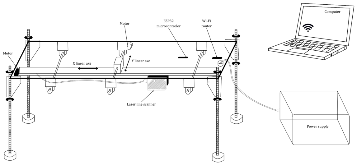
Figure 2.
Bottom view of the proposed portable laser triangulation scanner, highlighting the main components of the motion subsystem. XS and YS denote the sensor coordinates within the scanning area, whereas XD and YD indicate the displacements of the X- and Y-axis motorized linear stages, respectively.
Figure 2.
Bottom view of the proposed portable laser triangulation scanner, highlighting the main components of the motion subsystem. XS and YS denote the sensor coordinates within the scanning area, whereas XD and YD indicate the displacements of the X- and Y-axis motorized linear stages, respectively.
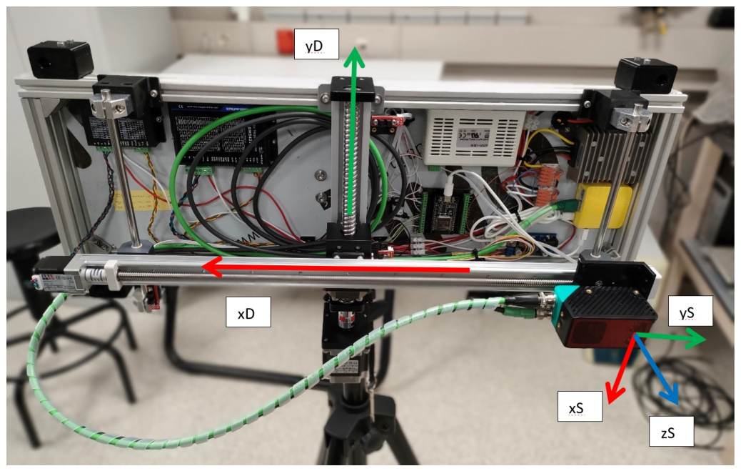
Figure 3.
Schematic diagram of the control system implemented in the proposed scanner, featuring an ESP32 microcontroller, stepper motor drivers, and the associated control electronics.
Figure 3.
Schematic diagram of the control system implemented in the proposed scanner, featuring an ESP32 microcontroller, stepper motor drivers, and the associated control electronics.
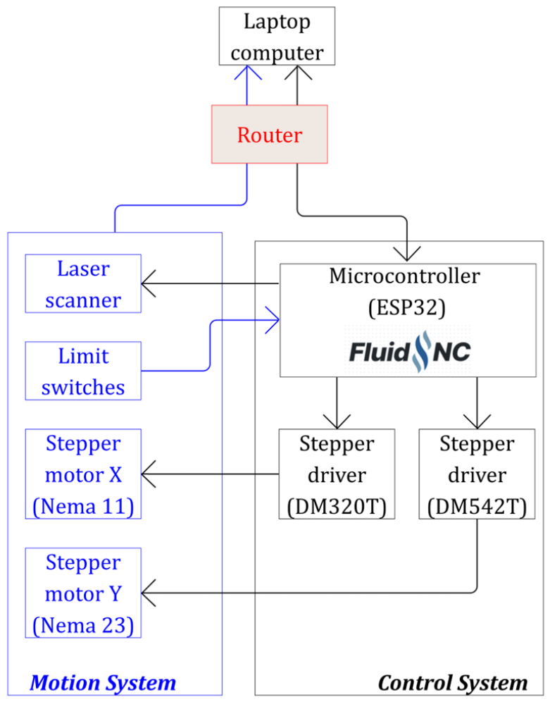
Figure 4.
(a) Digitization of a prehistoric hand axe using the proposed portable laser triangulation scanner; (b) resulting 3D model exported in PLY format.
Figure 4.
(a) Digitization of a prehistoric hand axe using the proposed portable laser triangulation scanner; (b) resulting 3D model exported in PLY format.
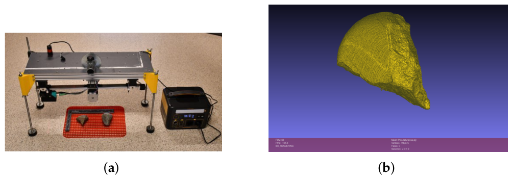
Figure 5.
Schematic diagram of the experimental setup used for calibration in both Z-axis (height measurement), and X-axis (horizontal field of view). Calibrated gauge blocks served as the reference standards in both procedures.
Figure 5.
Schematic diagram of the experimental setup used for calibration in both Z-axis (height measurement), and X-axis (horizontal field of view). Calibrated gauge blocks served as the reference standards in both procedures.
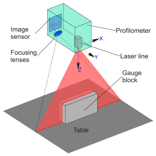
Figure 6.
(a) Calibration curve for the Z axis with the corresponding linear regression fit; (b) calibration curve for the X axis with the corresponding linear regression fit.
Figure 6.
(a) Calibration curve for the Z axis with the corresponding linear regression fit; (b) calibration curve for the X axis with the corresponding linear regression fit.
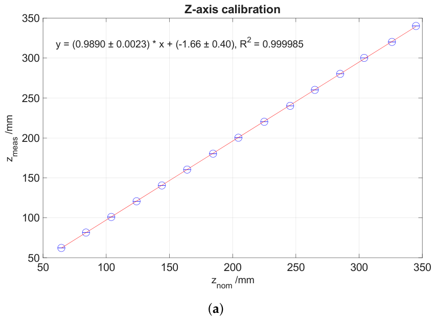
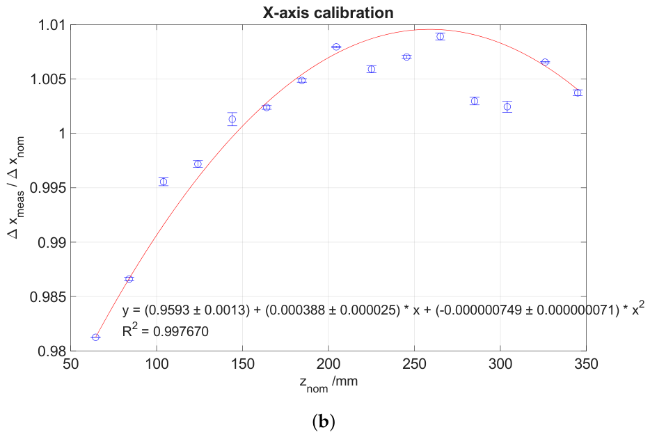
Figure 7.
(a) Scanning process of the theatrical mask using the proposed laser triangulation scanner; (b) resulting 3D reconstruction obtained by registering and merging three overlapping scans.
Figure 7.
(a) Scanning process of the theatrical mask using the proposed laser triangulation scanner; (b) resulting 3D reconstruction obtained by registering and merging three overlapping scans.
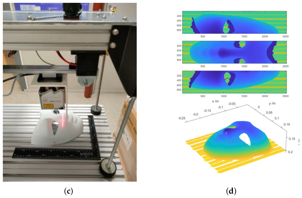
Figure 8.
(a) In-situ acquisition of the painted stone frieze with the proposed laser triangulation scanner; (b) corresponding reconstructed 3D surface model prior to laser cleaning.
Figure 8.
(a) In-situ acquisition of the painted stone frieze with the proposed laser triangulation scanner; (b) corresponding reconstructed 3D surface model prior to laser cleaning.
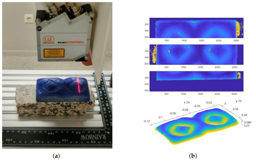
Figure 9.
(a) Detail of the laser-cleaned stone surface; (b) reconstructed 3D topography highlighting the preservation of fine surface features, including reliefs and texture variations.
Figure 9.
(a) Detail of the laser-cleaned stone surface; (b) reconstructed 3D topography highlighting the preservation of fine surface features, including reliefs and texture variations.
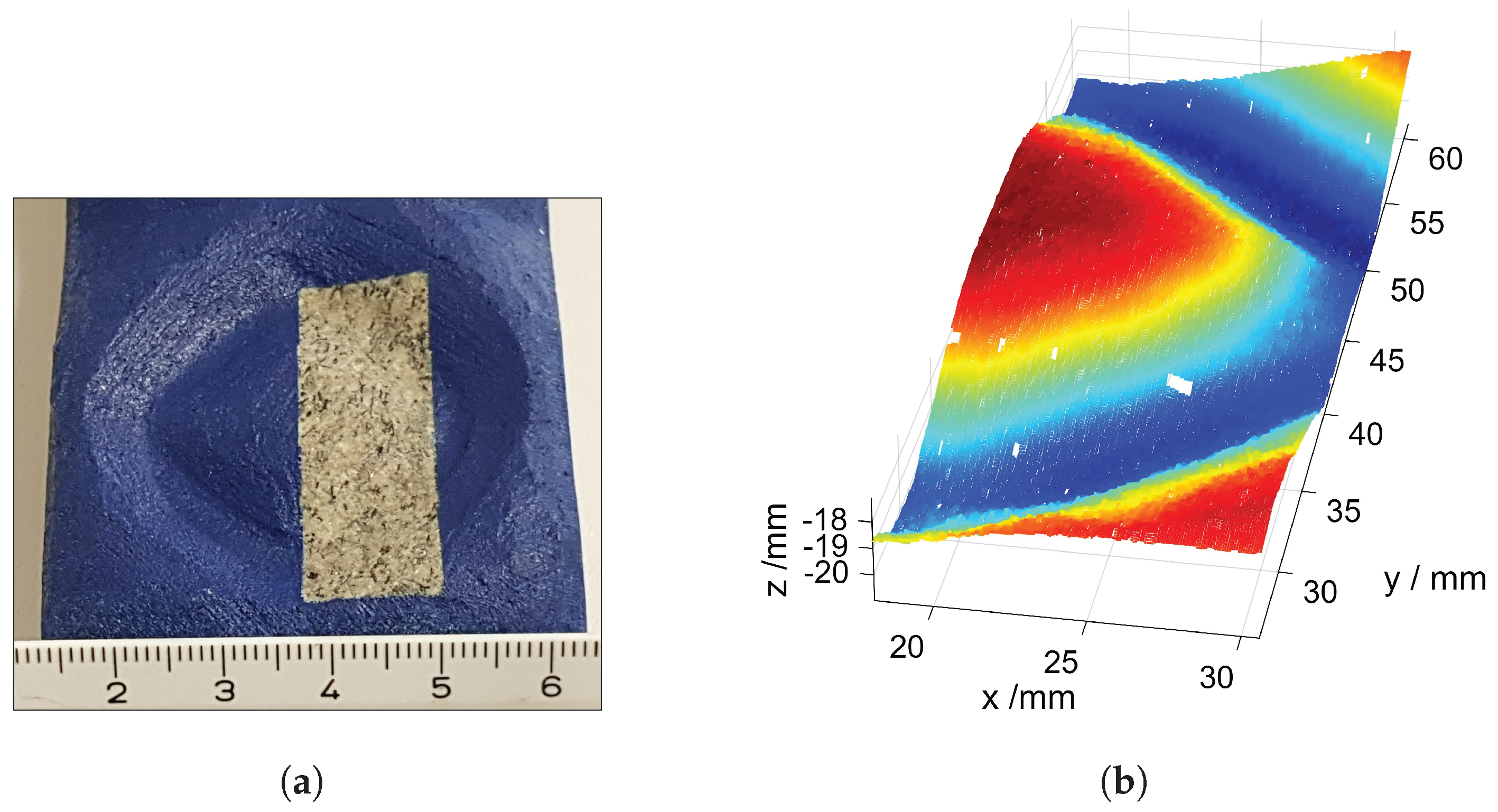
Figure 10.
(a) Example of the surface acquisition process for a bush-hammered granite specimen using the laser triangulation scanner; (b) corresponding reconstructed 3D surface topography.
Figure 10.
(a) Example of the surface acquisition process for a bush-hammered granite specimen using the laser triangulation scanner; (b) corresponding reconstructed 3D surface topography.
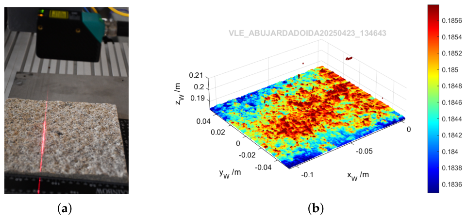

Table 1.
Areal roughness parameters calculated according to UNE-EN ISO 25178-2:2013 in the honed, sawn and bush-hammered granite surfaces.
Table 1.
Areal roughness parameters calculated according to UNE-EN ISO 25178-2:2013 in the honed, sawn and bush-hammered granite surfaces.
| Honned | 0.039 | 0.045 | -0.68 | 4.82 | 0.041 |
| Sawn | 0.243 | 0.313 | -0.26 | 3.30 | 0.166 |
| Bush-hammered | 0.444 | 0.490 | 0.066 | 2.813 | 0.291 |
Disclaimer/Publisher’s Note: The statements, opinions and data contained in all publications are solely those of the individual author(s) and contributor(s) and not of MDPI and/or the editor(s). MDPI and/or the editor(s) disclaim responsibility for any injury to people or property resulting from any ideas, methods, instructions or products referred to in the content. |
© 2026 by the authors. Licensee MDPI, Basel, Switzerland. This article is an open access article distributed under the terms and conditions of the Creative Commons Attribution (CC BY) license (http://creativecommons.org/licenses/by/4.0/).
Copyright: This open access article is published under a Creative Commons CC BY 4.0 license, which permit the free download, distribution, and reuse, provided that the author and preprint are cited in any reuse.


