
Submitted:
27 July 2026
Posted:
28 July 2026
You are already at the latest version
Abstract
We used High Power Impulse Magnetron sputtering (HiPIMS) to deposit Cr-Al-C-N thin films. Experiments were done by means of a commercial PVD unit equipped with a segmented sputter target. The target consisted of an upper half of Cr and a lower half of Al, respectively. While Cr-Al-N ternary coatings made by PVD are well understood, adding carbon to refine coating properties and applicability is much less explored. We added carbon in reactive sputter mode to possibly reduce internal stress and to add a friction reducing component. By varying the acetylene reactive gas flow and using the segmented target approach, different Al : Cr : C ratios could be sampled in an efficient way. Depending on positioning of the samples, Cr : Al ratios could be varied between about 4 : 1 and 1 : 2 while three different levels of carbon concentration were studied (0, 11, and 25 atomic % of coating composition including nitrogen). It was found that adding carbon on the first level is ef-fective in increasing hardness for coatings on the Cr rich side achieving maximum plastic hardness values over 40 GPa with a drop in hardness for higher Al contents. The cubic CrN phase with mostly 200 oriented planes was detected for all variants. With increasing shares of Al and C the crystallite size shrinks rapidly and the x-ray reflection of the 200 plane has less intensity which in-dicates a nano-crystalline coating structure. A turning test in stainless steel showed decreasing flank wear with higher Al content but a benefit of adding carbon could not be confirmed for the concen-trations sampled.
Keywords:
PVD
; HiPIMS
; CrAlCN
; wear mechanisms
; metal cutting
1. Introduction
CrN and CrAlN hard coatings are of interest to the cutting tool and other industries due to their high hardness, and ability to form protective oxides [1,2,3]. It is well known that adding aluminum to CrN is an effective way to improve for example hardness as long as the cubic phase is preserved which is the case up to a ratio of almost 70 : 30 atomic % Cr : Al [4,5]. The situation is very similar to the closely related Ti-Al-N ternary system. The addition of carbon to both CrN or CrAlN offers the possibility to further enhance coating properties especially when corrosion and friction act together [6,7,8]. As carbon is of similar atomic size to nitrogen it can easily replace it in the cubic lattice and will cause an increase in stress and hardness [9]. However, in contrast to nitrogen, carbon will eventually precipitate as graphite and substantially decrease hardness and hence resistance against abrasion [9,10]. Tang et al. varied the carbon content in AlCrCN films deposited by HiPIMS and confirmed an initial hardness increase until about 5 at. % C followed by a continuous drop [11]. Interestingly, the authors observed a stronger depletion of Cr while Al stays almost constant. It is assumed that mostly CrN bonds are weakened leading to a preferential secondary sputtering of Cr atoms (because of the substrate bias voltage). Tillmann et al. used statistical analysis to optimize CrAlCN coatings for a forming application [12]. It was found that in this case a high carbon content around 50 atomic % and sufficient hardness (adjusted by high substrate bias) work best although coatings become quite soft. Romero et al. stated that about 22 at. % of carbon is the best balance between mechanical and tribological properties in sputtered CrAlCN [8]. While there are numerous tribological studies, few results are available regarding the use of CrAlCN hard coatings for cutting tools [13,14,15]. As an example, Fang et al. tested AlCrCSiN coatings in dry turning of alloyed steel [13]. Surprisingly, they found that a carbon content of 1 at. % was already enough to reduce flank wear over AlCrSiN. Higher carbon concentrations led to much softer coatings and less wear resistance. The motivation for this study was hence twofold. First, we wanted to apply the combinatorial deposition approach to more efficiently explore the quarternary CrAlCN hard coating system. In addition, we wanted to understand and define a suitable range of coating properties for machining ferrous alloys that tend to stick to the cutting tool (such as austenitic stainless steel). A combination of abrasive and adhesive wear components is typically present in this machining application so adjusting the right amount of carbon for a good balance between hardness and friction behavior will help to optimize tool life.
2. Description of Experiments
All coatings were deposited in an industrial PVD furnace (Cemecon AG, Germany) equipped with one rectangular but segmented sputter target of 500 mm height and 88 mm width. The upper half (250x88 mm) of this target consisted of Cr while the lower half was made of Al (both metals with a purity of 99.95%, Avaluxe GmbH, Germany). Five samples were placed in front of the segmented target on a rod with vertical steps according to Figure 1. Samples consisted of Kennametal carbide grade K313 (ISO K05), style CNMG120408 for analytics and machining tests. Sample 3 is positioned right in front of the intersect of Cr and Al (defined as 0 mm). Positive values indicate positions above and negative values below this intersect as described earlier [16]. As this is an industrial deposition unit, samples rotated on spindles with closest and farthest distance from the target surface is about 100 and 220 mm, respectively. As sample height is only 4 mm, a gradient in chemical composition (i.e., Cr : Al ratio) on a given insert is considered negligible (< 1 at. %).
Cleaning was done in ultrasonically agitated and heated detergent bath for 1 min (T ~ 50 °C), then rinsed with ethanol and wiped dry with cleaning paper. The coating process itself consisted of the following steps: evacuation, radiation heating at about 700 °C (60 min), plasma etching (20 min), coating at about 500 °C (120 min), cooling to 250 °C before opening the coating chamber again. Mid-frequency argon ion etching was performed applying a (“bias”) voltage of 650 V to the substrate table at a frequency of 240 kHz. Important parameters for the HiPIMS deposition process are listed in Table 1. A 10% duty cycle was found necessary to ensure sufficient hardness of CrAlN. Argon pressure was set to 0.15 Pa (corresponding to about 200 sccm of Ar flow). Nitrogen and acetylene were added at a combined flow of 100 sccm with acetylene flows of 10 and 20 sccm, respectively. An additional set of CrAlN coated samples was prepared without acetylene. Furthermore, DC sputtering was used to prepare reference samples coated with CrAlCN. A monolithic, powder metallurgical Cr40Al60 target (values in atomic %) was taken in this case. DC power was set to 7.5 kW at an acetylene flow of 10 sccm.
Coating thickness was first determined by calotte grinding about 3 mm away from the sample edge. The calotte diameter was measured three times, averaged and then used to calibrate an x-ray fluorescence (XRF) spectrometer (XDAL, Fischer GmbH, Germany). This method is non-destructive and relatively fast, so more thickness data could be captured leading to improved statistics. Coating adhesion was evaluated by scratch testing using a ST200 instrument (Fischer GmbH, Germany). In this method, a diamond stylus (Rockwell C type with a tip radius of 0.2 mm) is moving along the surface at an increasing load of 0—70 N. Coating failure can be identified by continuous acoustic emissions in-situ or by inspecting the scratch by light microscopy after testing.
Elemental concentrations were measured by energy-dispersive x-ray spectroscopy (EDS) with a Phenom XL instrument (ThermoFisher, USA). The electron beam was accelerated by 15 keV scanning an area of about 130x130 µm. While the metals Al and Cr can be determined with an accuracy of about 1 atomic %, the lighter elements typically show increased scatter. Therefore, in this study any concentrations reported for C and N should be considered semi-quantitative and will be verified by more accurate methods in a forthcoming study. However, nitrogen is located next to carbon in the periodic system of elements (with similar atomic weight and x-ray scattering properties) and showed reasonable values around 50 at. % in every measurement. Therefore, it is assumed that values reported for carbon are a good first approximation.
Mechanical properties of the films such as universal hardness (HM), plastic hardness (H) and reduced modulus (E) were measured by nano-indentation method using a Fischerscope HM2000 (Fischer, Germany) according to ASTM E 2546. For better accuracy, the coated surface was polished at a slight angle to reduce scatter of the loading/ unloading curves. In order to keep the maximum indentation depth significantly smaller than the film thickness, a load of 10 mN was used without dwell time at maximum load. This resulted in a typical penetration depth of about 0.1 µm. 12 indentations were performed on each sample, scatter of results typically stayed around 5% (of the average value).
X-ray analyses were performed with a MF600 unit (Rigaku, Japan) using Cu Kα radiation generated at a voltage of 40 kV and 20 mA anode current. A Ni K beta Filter was present in combination with a Soller slit size of 0.2 mm. An angular range of 30 to 60° was scanned in a Bragg-Brentano setup in order to capture the most intense lower indexed lattice planes.
Wear resistance (performance) of the different coating variants was evaluated by a turning test on a CNC lathe. Coolant was used to extend tool life. Cutting parameters were set as follows: cutting speed 140 m/min, depth of cut 1 mm, feed 0.2 mm/revolution. Stainless austenitic steel grade EN DIN 1.4301 (Cr-Ni alloyed, corresponds to AISI 304) was used with a tensile strength of close to 600 MPa. Inserts were taken at 2 and 4 min (test end) for visual inspection of wear at flank and rake face. Flank wear progress was measured with light microscopy (VHX system, Keyence, Japan). Each test was repeated two times and resulting flank wear values were averaged.
3. Results & Discussion
3.1. Thickness and Adhesion
A target thickness of 1.5 µm was intended and could be obtained on average with some scatter depending on measuring spot location. As an example, Table 2 lists values obtained for an acetylene flow of 10 sccm along with a typical calotte crater image. It is interesting to note that there is a potential trend to lower thickness from position 1 to 5 which is also found for other experiments. This is most likely caused by a slightly lower sputter yield of Al compared to Cr under irradiation of Ar ions. It is not assumed that the minor difference in thickness will significantly affect machining test results.
Figure 2 shows images of the scratch test end section (where a maximum load of 70 N is reached). All coatings without and with an acetylene flow of 10 sccm passed scratch testing up to 70 N and no coating delamination was observed at the bottom of the tracks. However, with an acetylene flow of 20 sccm there was delamination for samples of positions 3 to 5 starting at 50 N (pos. 3) and 30 N (pos. 5), respectively as shown in Figure 2b. This reduced adhesion is likely caused by missing crystallinity and deficient matching to the substrate. The scratch track boundaries are also smoother in Figure 2b indicating softer (more ductile) coatings.
3.2. Composition, Mechanical Properties, and Structure
One of the main properties of any coating is the concentration of elements present. Table 3 shows trends for the 5 vertical positions sampled depending on the flow of acetylene reactive gas. The Cr : Al ratio is expressed as relative share of Cr in atomic % (adding up to 100%) whereas C and N are measured concentration in atomic % (all elements in the coating adding up to 100%). As expected, moving from position 1 (top) to 5 (bottom), the concentration of Cr drops from about 80 to 30 atomic %. Al is correspondingly increasing from about 20 to 70 atomic %). Adding acetylene seems to reduce the amount of Al more than Cr contrary to the findings of Tang et al. [11]. The reason may be stronger bonding of Cr-C than Al-C.
The deposition with Cr40Al60 targets in DC mode and 10 sccm of acetylene reactive gas flow resulted in a Cr/(Al+Cr) ratio of 0.42 and an elemental concentration of 12: 49 atomic % being close to the values obtained for the HiPIMS variant obtained with the same amount of acetylene at position 4 at the same flow of acetylene (Table 3).
Figure 3 shows the trend for plastic hardness and elastic modulus for all three variants. Hardness of CrAlN coatings is constantly increasing from positions 1 to 5 and saturates at values of almost 45 GPa obtained even for the highest Al content of 72 at. %. Depending on acetylene reactive gas flow the trends change considerably. For the highest flow of 20 sccm a constant decrease of hardness is observed dropping from 35 to 25 GPa. It can be assumed that Cr-C bonds are diminished when an increasing amount of lattice sites is occupied with Al atoms which are not known to form equally strong bonds to carbon. The hardness curve for an acetylene flow of 10 sccm reveals the most interesting behavior depending on sample position. For Cr : Al atomic ratios of > 50 atomic % (positions 1-3), hardness is initially increasing. Al is substituting Cr in the lattice while carbon does the same with nitrogen atoms, distortion and local stresses go up which typically results in increased hardness. However, this trend stops at position 4 at a ratio of Cr : Al < 45 atomic % where the softer hexagonal AlN phase is expected to form. Compared to CrAlN this transition between cubic and hexagonal phase occurs earlier with carbon present. Zhang et al. reported a similar decrease in hardness but attributed this to graphite precipitation [15]. Interestingly, the DC sputtered variant comparable in composition to coating of position 4 (acetylene flow of 10 sccm) only shows a hardness around 25 GPa and a modulus around 350 GPa. This finding confirms the benefit of increased ionization obtained with HiPIMS at low duty cycles of around 10%.
The modulus values which are also shown in Figure 3 (bottom diagram) contain further information. Clearly, CrAlN shows higher values overall starting at position 1 with about 450 GPa which increase with higher Al : Cr ratios to over 500 GPa. These high values typically indicate a fully cubic nitride structure. The modulus values for CrAlCN obtained with 10 and 20 sccm of acetylene gas are consistently lower and decline steadily from about 400 to 300 GPa for positions 1 to 5. Given the closeness of these curves and similar dependency on Al concentration it is assumed that formation of the hexagonal AlN phase is the main cause for decreasing modulus values [13].
Figure 4 visualizes x-ray diffraction data of samples taken from positions 1, 3, 5. Diffraction signal intensity is plotted in logarithmic scale. Reflections from the carbide substrate, i.e., remain unchanged in shape and position and serve as reference, i.e., hexagonal WC (100) at 35.7° and cubic Co (111) at 44.2°. The graphs for CrAlN coatings at the top clearly show a cubic CrN phase with reflection of planes (111) and (200) around 37.6° and 43.7°, respectively. Transitioning from position 1 to 5 leads to a reduction in peak signal intensity and a shift to larger diffraction angles as Al is gradually replacing Cr on its lattice sites. CrAlCN coatings obtained with adding 10 sccm of acetylene reactive gas do not clearly show a signal of 111 crystal planes anymore. The peak coming from the 200 plane is reduced in intensity and broadened with signal getting fainter from positions 1 to 5 (increasing Al concentration). A similar behavior was described by Zhou et al. for arced AlCrCN with increasing acetylene gas flows [10]. The graph at the bottom is a diffraction diagram of a DC sputtered CrAlCN coating (Al60Cr40 targets, acetylene flow of 10 sccm) for comparison. It resembles the graphs obtained for positions 5 but additionally seems to indicate the presence of hexagonal AlN (peak at 31.8°, 1010 plane). Unlike Romero et al. we were not able to identify any carbide phase [8] or precipitated carbon with the methods available. X-ray photoelectron spectroscopy [11] or Raman spectroscopy [13] were previously used to study bonding of carbon in CrAlCN coatings.
3.3. Metal cutting test
As described in the experimental section a turning test was done to evaluate wear behavior of differently coated carbide inserts when machining a material that tends to adhere to the cutting tool. Two batches with hardest coatings were compared, CrAlN and CrAlCN deposited with an acetylene flow of 10 sccm which according to Figure 3 was overall significantly harder than coating variants obtained with higher reactive gas flow. The relatively soft variants obtained with a higher acetylene gas flow were hence not tested further. Figure 5 shows the resulting flank wear after 4 min of turning stainless steel. observed together with two exemplary images of the rake face after completing the test, positions 1 (Cr rich) to 5 (Al rich) are again shown. In the case of CrAlN, there is a trend to reduced flank wear marks for increasing Al contents and is lowest for the highest content of Al. This trend is in accordance with trends in hardness and modulus, so an abrasive wear mechanism is assumed. CrAlCN coatings showed a less clear trend depending on Cr:Al ratio and a minimum may be observed at position 4. This finding could be explained by competing effects of increasing hardness and decreasing modulus reaching an optimum near position 4 at a ratio of Cr : Al ~ 45 : 55 atomic % (Table 2). A lower ratio of 28 : 72 atomic % (or higher Al concentration) is possible for CrAlN. Therefore, carbon addition reduces the allowable Al content to reach optimum tool life). In fact, Fang et al. used Al70Cr30 targets and could only add about 2 atomic % carbon [13].
Finally, Figure 6 shows the rake face of samples position 3 (CrAlN, CrAlCN deposited with an acetylene flow of 10 sccm). The wear observed at these edges looks comparable with clearly visible crater wear (upper brighter area) and workpiece adhesion directly below the curved cutting edge. A qualitative EDS spot measurement (cross close to image center) reveals the presence of metals Fe, Cr, Ni of the machined stainless steel.
It is obvious that wear progresses quite fast with the cutting conditions applied. Substrate material is exposed early and determines further wear behavior. This makes it difficult to detect significant differences that are caused by differing coating properties. Therefore, further testing is planned by both tribometry and metal cutting (with reduced speed and increased coating thickness).
4. Conclusions
CrAlCN thin films were deposited in an industrial scale HiPIMS PVD unit with a target consisting of an upper Cr and lower Al segment. With this arrangement various elemental ratios could be sampled in a single coating process. Five vertical positions were chosen in this study. A further variable was explored by adding acetylene to nitrogen reactive gas. It was found that acetylene is much more effective than nitrogen in poisoning the target surface likely because it can be ionized easier with its relatively weak C-H bonds. The face-centered cubic Cr(Al)N phase was present for all Cr : Al : C ratios. X-ray diffraction showed decreasing signal intensity with increasing Al content and with higher acetylene flows. CrAlN coatings without carbon were already very hard with a maximum plastic hardness of over 40 GPa at a Cr : Al atomic ratio of about 40 : 60. By adding about 10 at. % carbon a comparable peak hardness of over 40 GPa occurred at lower, roughly equal Cr : Al atomic ratio. However, modulus of all carbon-enriched coating variants decreased with increasing Al concentration. The most likely explanation is formation of the hexagonal phase which is promoted by increasing carbon concentration. Coatings deposited with the highest acetylene flow of 20 sccm showed rapid decline in hardness with increasing Al and were therefore not considered for wear testing. A turning test in stainless steel did not show improved tool life with CrAlCN coatings (acetylene flow of 10 sccm) when compared to CrAlN coated inserts. Carbide substrate was exposed early at the cutting edge in all cases so that rapid workpiece adherence occurred at the flank face. Further testing at less severe cutting conditions accompanied by tribometer studies are planned in order to better detect effects of differing coating properties.
Funding
This research received no external funding.
Conflicts of Interest
The author declares that there are no conflicts of interest.
References
- Tillmann, W.; Stangier, D.; Laemmerhirt, I.A.; Biermann, D.; Freiburg, D. Investigation of the tribological properties of high-feed milled structures and Cr-based hard PVD-coatings. Vacuum 2016, 131, 5–13. [Google Scholar] [CrossRef]
- Mo, J. L.; Zhu, M. H.; Leyland, A.; Matthews, A. Impact wear and abrasion resistance of CrN, AlCrN and AlTiN PVD coatings. Surf. Coat. Technol. 2013, 215, 170–177. [Google Scholar] [CrossRef]
- Bagcivan, N.; Bobzin, K.; Theiss, S. (Cr1-xAlx)N: A comparison of direct current, middle frequency pulsed and high power pulsed magnetron sputtering for injection molding components. Thin Sol. Films 2013, 528, 180–186. [Google Scholar] [CrossRef]
- Reiter, A.; Derflinger, V.H.; Hanselmann, B.; Bachmann, T.; Sartory, B. Investigation of the properties of Al1-xCrxN coatings prepared by cathodic arc evaporation. Surf. Coat. Technol. 2005, 200, 2114–2122. [Google Scholar] [CrossRef]
- Weirather, T.; Czettl, C.; Polcik, P.; Kathrein, M.; Mitterer, C. Industrial-scale deposition of Cr1-xAlxN coatings with 0.21. Surf. Coat. Technol. 2013, 232, 303–310. [Google Scholar] [CrossRef]
- Xu, X.; Sun, J.; Li, Z.; Su, F. Microstructure, electrochemical and tribocorrosion behaviors of CrCN nanocomposite coating with various carbon contents. Surf. Coat. Technol. 2021, 411, 126997. [Google Scholar] [CrossRef]
- Soleimani, M.; Alhosseini, A.F.; Elmkhah, H.; Babaei, K.; Imantalab, O. A comparison of tribological and corrosion behavior of PVD-deposited CrN/CrAlN and CrCN/CrAlCN nanostructured coatings. Ceram. Int. 2023, 49(1), 5029–5041. [Google Scholar] [CrossRef]
- Romero, E.C.; Botero, M.G.; Tillmann, W.; Osorio, F.B.; Gaitan, G.B. Influence of carbon content on the microstructure, mechanical and tribological properties of CrAlCN coatings deposited by DC unbalanced magnetron sputtering. Bull. Mat. Sci. 2018, 41(4), 97. [Google Scholar] [CrossRef]
- Almer, J.; Oden, M.; Hakansson, G. Microstructure, stress and mechanical properties of arc-evaporated Cr-C-N coatings. Thin So. Films 2001, 385(1-2), 190–197. [Google Scholar] [CrossRef]
- Zhou, Q.; Wang, X.; Huang, B.; Chen, Q.; Liang, D.; Zhang, E. Investigation of the microstructure and tribological properties of CrAlCN composite coatings with various acetylene flow rates. Thin Sol. Films 2026, 835, 140859. [Google Scholar] [CrossRef]
- Tang, J.F.; Wang, S.H.; Yang, F.C.; Chang, C.L. Effects of carbon doping and DC bias voltage on microstructure and mechanical properties of AlCrCN films synthesized via HiPIMS. Materials 2022, 15(16), 5729. [Google Scholar] [CrossRef] [PubMed]
- Tillmann, W.; Stangier, D.; Schröder, P. Investigation and optimization of the tribo-mechanical properties of CrAlCN coatings using Design of Experiments. Surf. Coat. Technol. 2016, 308, 147–157. [Google Scholar] [CrossRef]
- Fang, W.; Chen, J.; Zhou, Q.; Xue, H.; Cai, F.; Fang, L.; Zhang, S. Microstructure, mechanical properties and high speed dry-cutting performance of AlCrSiCN composite coatings. J. Mat. Res. Technol. 2023, 25, 1800–1812. [Google Scholar] [CrossRef]
- Song, J.; Tian, H.; Li, J.; Zhang, P.; Hong, Z.; An, S. Study on the working performance of CrAlCN coated and uncoated carbide twist drill. Optik 2022, 270, 169948. [Google Scholar] [CrossRef]
- Zhang, M.; Zhou, F.; Fang, H.; Wu, Z. Influence of C content on the structure, mechanical and tribological properties of CrAlCN films in air and water-based cutting fluid. Appl. Phys. A 2020, 126, 589. [Google Scholar] [CrossRef]
- Kohlscheen, J.; Bareiss, C. Combinatorial deposition and wear testing of HiPIMS W-C films. Coatings 2025, 15(1), 115. [Google Scholar] [CrossRef]
- Liu, Y.; Ding, J. C.; Zhang, B. R.; Chen, J. J.; Tang, C. R.; Zhu, R. Y.; Zhen, J. Effect of duty cycle on microstructure and mechanical properties of AlCrN coatings. Vacuum 2022, 205, 111409. [Google Scholar] [CrossRef]
Figure 1.
Schematic drawing of sample positions 1-5, vertically aligned in front of the segmented Cr/Al target.
Figure 1.
Schematic drawing of sample positions 1-5, vertically aligned in front of the segmented Cr/Al target.
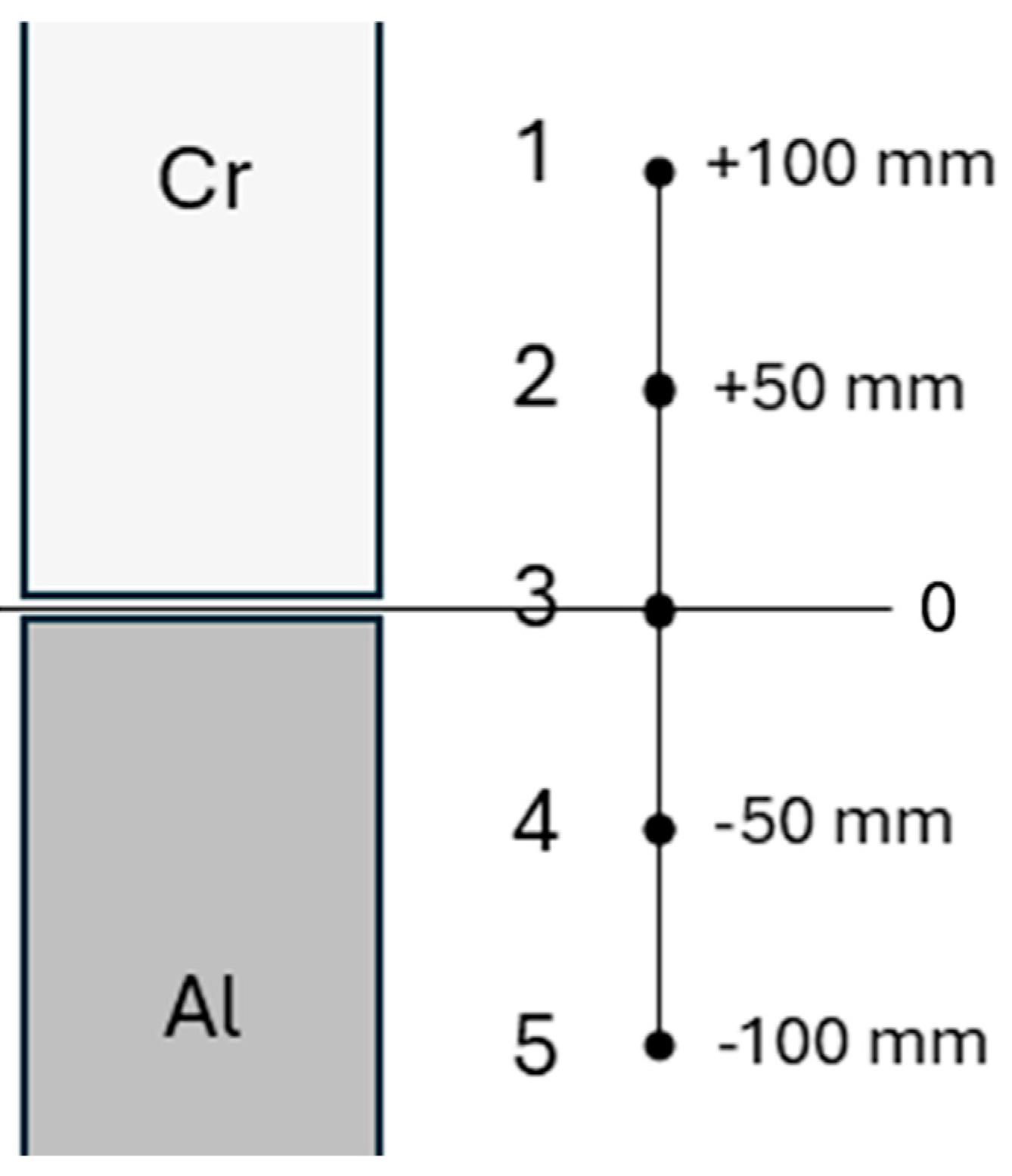
Figure 2.
Exemplary images of scratch tracks at maximum load of 70 N, samples of positions 1,3, 5 with acetylene flows of 10 sccm (left) and 20 sccm (right).
Figure 2.
Exemplary images of scratch tracks at maximum load of 70 N, samples of positions 1,3, 5 with acetylene flows of 10 sccm (left) and 20 sccm (right).
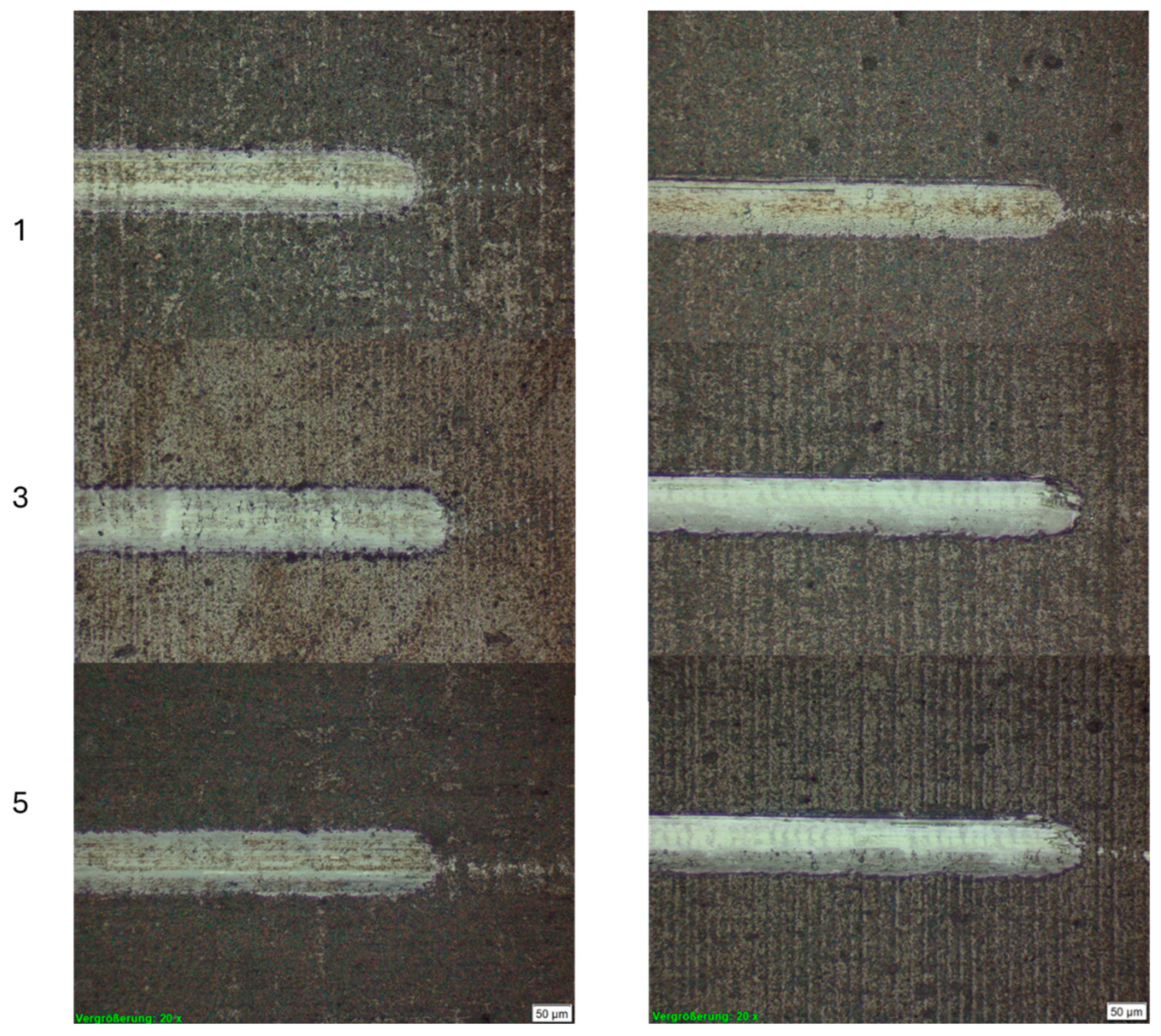
Figure 3.
Plastic hardness and modulus depending on vertical position and acetylene gas flow (e.g., “Ac 10” indicates a flow 10 sccm).
Figure 3.
Plastic hardness and modulus depending on vertical position and acetylene gas flow (e.g., “Ac 10” indicates a flow 10 sccm).
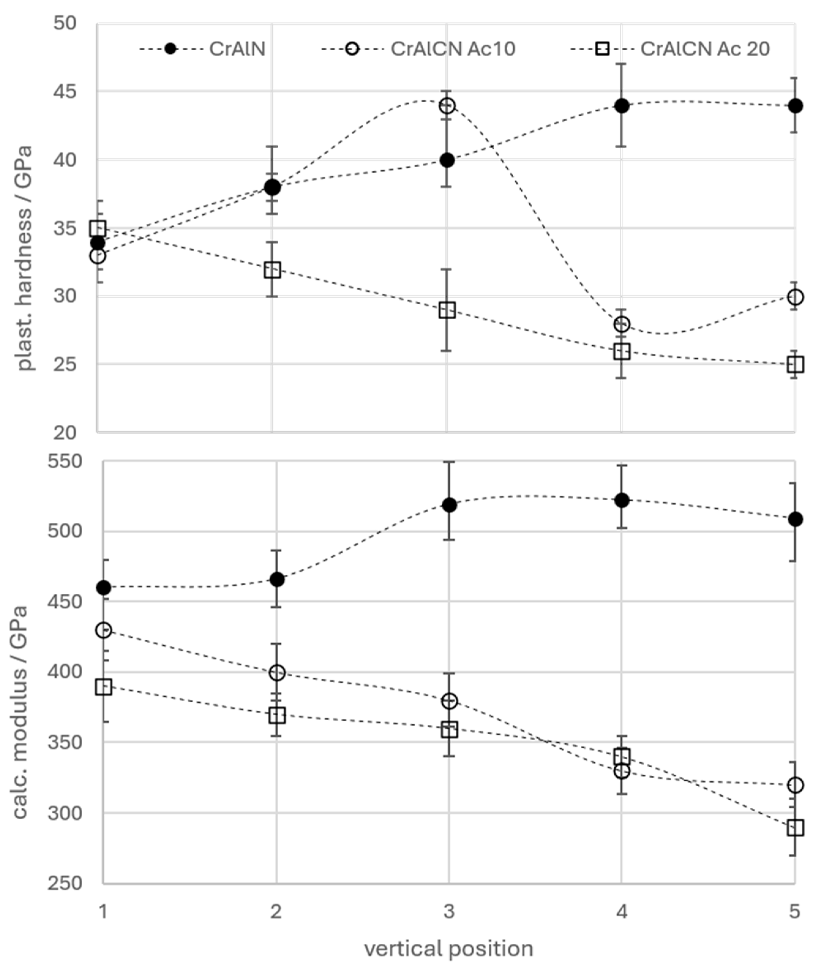
Figure 4.
X-ray diffraction diagrams of CrAlCN coated samples from pos. 1,3,5 deposited without and with acetylene gas flow of 10 sccm (HiPIMS process middle, DC process lower graph).
Figure 4.
X-ray diffraction diagrams of CrAlCN coated samples from pos. 1,3,5 deposited without and with acetylene gas flow of 10 sccm (HiPIMS process middle, DC process lower graph).
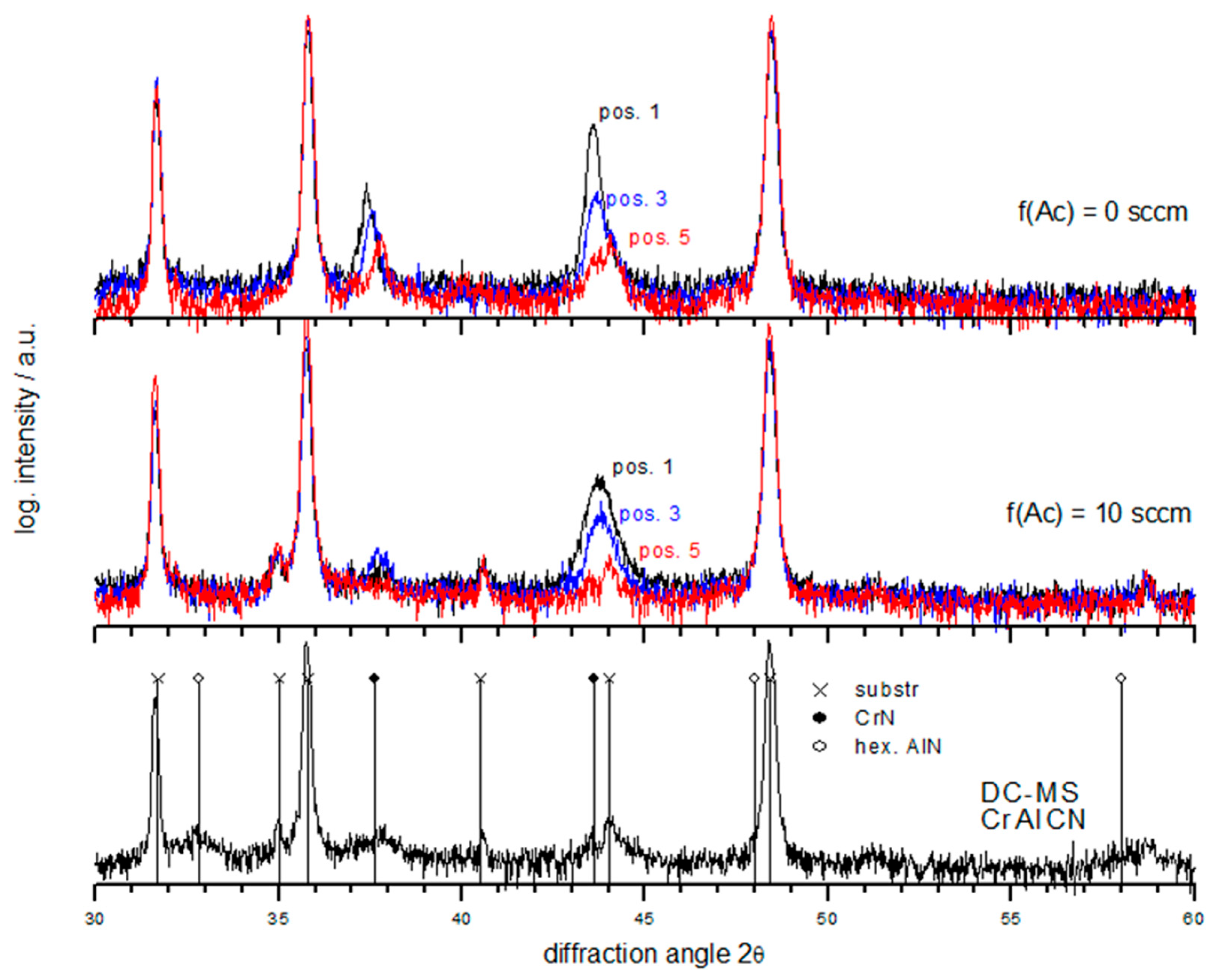
Figure 5.
Turning test flank wear after 10 min of continuous turning of AISI 304 depending on sample position, coatings CrAlN and CrAlCN (acetylene gas flow of 10 sccm, “Ac 10”).
Figure 5.
Turning test flank wear after 10 min of continuous turning of AISI 304 depending on sample position, coatings CrAlN and CrAlCN (acetylene gas flow of 10 sccm, “Ac 10”).
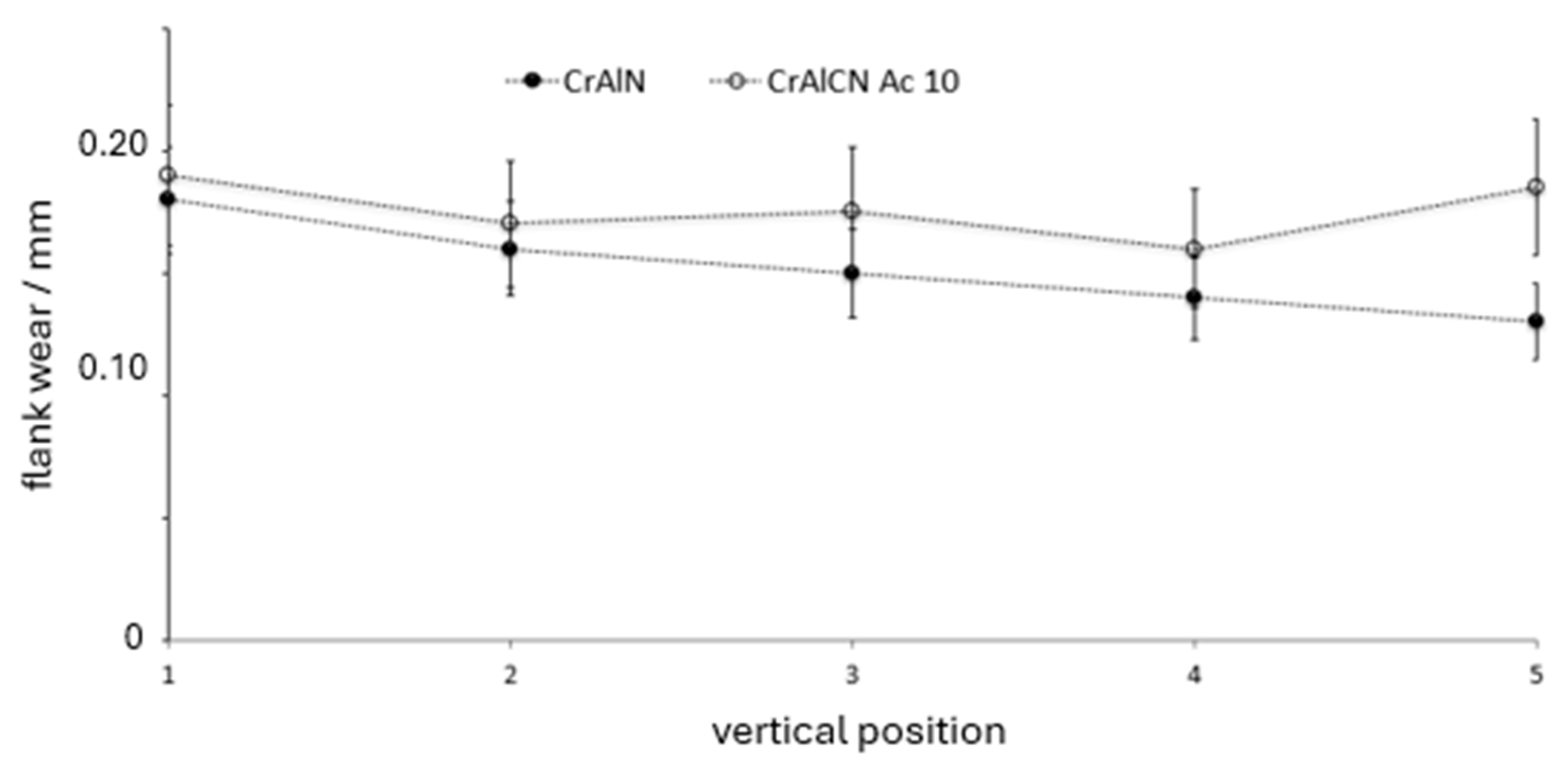
Figure 6.
Qualitative EDS of workpiece material adhered to the cutting edge after 4 min of turning, samples of position 3, coatings CrAlN (left) and CrAlCN (Ac = 10 sccm, right).
Figure 6.
Qualitative EDS of workpiece material adhered to the cutting edge after 4 min of turning, samples of position 3, coatings CrAlN (left) and CrAlCN (Ac = 10 sccm, right).
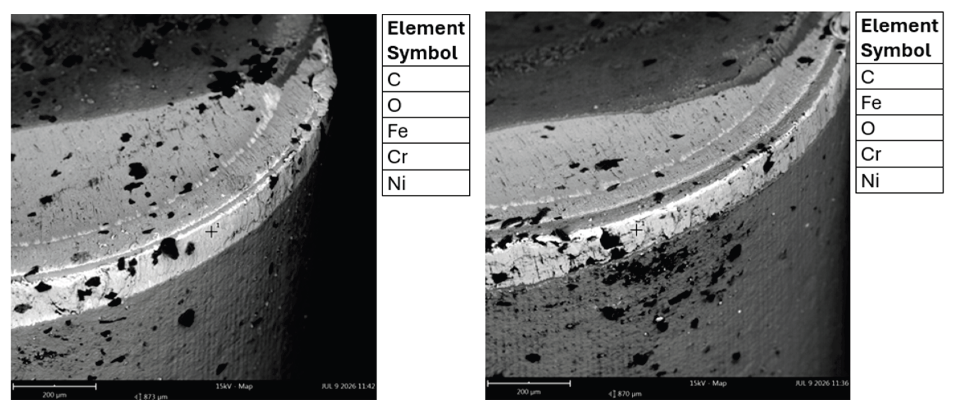

Table 1.
Overview of main deposition parameters used in HiPIMS deposition of CrAlCN.
| Target power | Pulse freq. | Pulse-on time | C2H2 flow | Bias voltage |
|---|---|---|---|---|
| 7.5 kW | 2000 Hz | 50 µs (10%) | 0/10/20 sccm | 100 V |
Table 2.
Coating thickness distribution for an acetylene flow of 10 sccm (all in µm), values determined by XRF, example of calotte used for calibration (right image).
Table 2.
Coating thickness distribution for an acetylene flow of 10 sccm (all in µm), values determined by XRF, example of calotte used for calibration (right image).
| pos. | min-max | average | 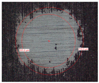 |
| 1 2 3 4 5 |
1.56-1.80 1.54-1.80 1.36-1.60 1.35-1.61 1.37-1.59 |
1.63 1.67 1.44 1.45 1.47 |
Table 3.
Listing of Cr/(Al+Cr) ratios and concentration of C, N (in at. %) depending on vertical sample position and acetylene flows (top row, in sccm).
Table 3.
Listing of Cr/(Al+Cr) ratios and concentration of C, N (in at. %) depending on vertical sample position and acetylene flows (top row, in sccm).
| position | f(Ac) = 0 | f(Ac)=10 | f(Ac)=20 |
|---|---|---|---|
| 1 2 3 4 5 |
0.81/0/52 0.71/0/51 0.55/0/53 0.34/0/54 0.28/0/55 |
0.83/11/47 0.74/11/49 0.61/12/50 0.45/12/50 0.32/12/51 |
0.82/24/43 0.74/26/44 0.60/24/46 0.48/25/45 0.35/29/45 |
Disclaimer/Publisher’s Note: The statements, opinions and data contained in all publications are solely those of the individual author(s) and contributor(s) and not of MDPI and/or the editor(s). MDPI and/or the editor(s) disclaim responsibility for any injury to people or property resulting from any ideas, methods, instructions or products referred to in the content. |
© 2026 by the author. Licensee MDPI, Basel, Switzerland. This article is an open access article distributed under the terms and conditions of the Creative Commons Attribution (CC BY) license (http://creativecommons.org/licenses/by/4.0/).
Copyright: This open access article is published under a Creative Commons CC BY 4.0 license, which permit the free download, distribution, and reuse, provided that the author and preprint are cited in any reuse.


