
Submitted:
24 July 2026
Posted:
27 July 2026
You are already at the latest version
Abstract
This paper presents the design, simulation, and experimental validation of a Genetic Algorithm (GA)-optimized Active Disturbance Rejection Controller (ADRC) for voltage regulation in a standalone Doubly Fed Induction Generator (DFIG)-based Wind Energy Conversion System (WECS). The proposed system is designed to operate under variable wind conditions and nonlinear load profiles, with a battery energy storage system (BESS) connected to the rotor side to enhance performance and stability. A battery management algorithm is incorporated to ensure safe operation and maintain the state of charge (SOC) within optimal limits. The control strategy is evaluated through detailed simulations in MATLAB/Simulink and validated experimentally using a real-time dSPACE 1104 platform. Results show that the GA-tuned ADRC offers superior voltage regulation, fast transient response, and strong disturbance rejection compared to conventional PI controllers. Moreover, the integration of the battery management algorithm ensures reliable energy flow and SOC control, confirming the practical feasibility of the proposed method for isolated renewable energy applications.
Keywords:
wind energy
; battery management algorithm
; doubly fed induction generator
; ADRC control
; standalone
; the genetic algorithm
1. Introduction
Utilizing and transforming renewable energies is very important nowadays to address issues like energy scarcity and environmental degradation, due to the climate change and high co2 emissions [1]. A dependable, clean, and environmentally renewable resource like wind energy has grown in popularity in recent years [2]. Industrial wind energy conversion systems were mostly divided into two categories, those who are connected and those isolated from the distribution grid [3]. In remote and off-grid regions, wind energy systems offer a sustainable and decentralized alternative for power generation and isolated charging applications, such as rural production stations or standalone telecommunication stations [3,4].
The need for sophisticated control systems that can guarantee dependable and stable operation under extremely variable environmental conditions has expanded dramatically due to the quick development of renewable energy technology. Due to its technological maturity, environmental sustainability, and steadily declining installation prices, wind energy has emerged as one of the most appealing renewable energy options. However, the stochastic nature of wind speed causes significant variations in the power produced, particularly in stand-alone systems where power imbalances cannot be corrected by the electrical grid. Therefore, one of the key technological issues for isolated wind energy conversion systems continues to be maintaining voltage stability, frequency management, and power quality.
At isolated DFIG-based wind energy conversion systems (WECS), energy fluctuations caused by an intermittent nature for wind pose significant challenges for voltage and frequency stability. To enhance dynamic performance and system reliability, a battery energy storage system (BESS) is integrated into the rotor circuit of the DFIG via a buck-boost DC-DC converter. This configuration enables a transfer to power among a battery and a rotor-side converter, providing additional degrees for control during transients, start-up, or low wind conditions.
The battery system complements the ADRC-based control of the DFIG by:
- Assisting in frequency and voltage regulation during low wind speeds or rapid load changes.
- Supporting black start capability in isolated systems.
- Enhancing the disturbance rejection capability of ADRC by dynamically managing power imbalance.
In isolated DFIG–battery systems, a Battery Energy Storage System (BESS) is interfaced through a DC link between the consecutive converters typically via a bidirectional DC–DC (buck–boost) converter—to the rotor-side converter (RSC) [1,4]. During periods of excess generation (high wind/no load), the BESS charges; during under generation (low wind/high load), it discharges to support rotor excitation and maintain the DC-link voltage [4,5].
Due to their high efficiency, adaptable management for active and reactive power, and lower power converter rating, doubly fed induction generators (DFIGs) are frequently utilised in variable-speed wind energy conversion systems (WECS) [5]. Still, when operating in stand-alone mode the control of DFIG-based systems becomes more complex. The stator side of the machine must maintain a stable voltage and frequency under varying wind and load conditions.
DFIG-based wind energy conversion systems have a number for technical advantages over fixed-speed wind generators, such as variable-speed operation, independent active and reactive power control, lower converter rating, and increased energy extraction efficiency over a broad operating range. DFIG technology is especially well-suited for medium- and high-power wind applications because of these features. However, in standalone operating conditions, the lack of grid support necessitates that the control system independently regulate the stator voltage and frequency while concurrently compensating for abrupt load disturbances and variations in wind speed, making the overall control problem much more difficult.
In addition to this a DFIG-based WECS poses a difficult issue with power engineers due to its complex and nonlinear multivariable dynamic model, highly coupled state space representation and other significant limitations, such as the starting problem and angle of charge [2,3,4,5].
To get past the unavoidable uncertainty, including variations in wind speed and the outside load. Supplying reactive or nonlinear loads, including RC (resistive-capacitive) loads, which produce dynamic reactive power needs and phase imbalances, makes this work more difficult [4,5,6].
A battery must be attached for a rotor-side converter that uses a stator produced power to charge. Thus, a strong control strategy is required. In such isolated setups, conventional control strategies like field-oriented control (FOC) Proportional-Integral (PI) controllers that are cascaded are frequently employed [4].
Although efficient into steady-state operation, PI controllers may lack robustness and adaptability in the face of disturbances, nonlinearities, and time-varying parameters issues that are prevalent in real-world wind energy applications [5].
For both isolated and grid-connected DFIG-based WT, numerous dependable controllers have been put into place. in recent years, relying on advancements in control theory and implementation. These control strategies incorporate SMC (Sliding Mode Control).[7], Model Predictive Control (MPC) [8], and approaches based on fuzzy logic or neural networks [9]. Despite promising performance in simulation studies, these techniques often suffer from implementation difficulties due to high computational demands and sensitivity to modeling inaccuracies.
The development of sophisticated control methods for freestanding DFIG-based WECS has received much research attention in recent years [9]. Although Sliding Mode Control (SMC) is quite resistant against parameter uncertainty, it typically experiences unwanted chattering [10]. Superior dynamic performance and efficient constraint handling are provided by Model Predictive Control (MPC), but its implementation necessitates large computer resources and a precise prediction model. Although their practical implementation frequently remains computationally costly, artificial intelligence-based techniques such as fuzzy logic, neural networks, and deep learning approaches have also shown promising results [11]. Thus, a control method that provides resilience, computational simplicity, and real-time implementation capacity all at once is still required.
Active Disturbance Rejection Control (ADRC) has emerged as a robust and model-independent control strategy that estimates and compensates for both internal uncertainties and external disturbances in real-time [12]. Its key advantage lies in its ability to deliver reliable performance without requiring an accurate model of the plant [12,13].
However, determining appropriate tuning parameters for the ADRC such as observer and controller gains can be challenging and system-specific. To address this challenge, several works have explored metaheuristic algorithms for tuning ADRC or PI parameters, particularly the Genetic Algorithm (GA), which has shown promising results in standalone and fault-tolerant DFIG model [14,15].
In that study, a GA is used for optimally tune the ADRC controller to a stand-alone DFIG-based wind energy system supplying an RC nonlinear load. A system is modeled and simulated in MATLAB/Simulink to assess dynamic behavior, displaying a model at different wind speeds and load profiles. An GA is used offline to minimize objective functions related to voltage regulation quality, dynamic response, and robustness [16].
While several studies have focused on conventional PI control or ADRC applied in grid-connected scenarios, few have investigated the application for intelligent tuning techniques for enhance ADRC performance in stand-alone DFIG-based systems. The primary impact for that paper lies at an integration and simulation-based validation of a GA-tuned ADRC strategy for isolated wind energy applications [17]. A simulation results demonstrate that the suggested method offers improved voltage and frequency stability, faster transient response, and better disturbance rejection compared to classical control approaches [18].
This work contributes to the development of more robust and adaptive control strategies to renewable energy systems operating in isolated conditions. The simulation-and the experimental tests offer a valuable step toward practical implementation in real-world embedded systems for decentralized energy supply [19,20].
The following is a summary of this work's primary contributions: (i) a development for a standalone DFIG-based wind energy conversion system integrating a Battery Energy Storage System (BESS); (ii) an implementation of a battery management algorithm to control a charging and discharging processes while maintaining the battery state of charge within safe operating limits; (iii) an optimization of the Active Disturbance Rejection Controller using a Genetic Algorithm to improve voltage regulation and disturbance rejection capabilities; (iv) a comprehensive performance evaluation under variable wind speed and nonlinear load conditions using MATLAB/Simulink; and (v) real-time experimental validation using a dSPACE DS1104 platform. The data collected show that the suggested GA-optimized ADRC significantly improves voltage regulation accuracy, transient response, robustness against disturbances, and overall system stability compared with conventional PI-based control strategies.
2. Materials and Methods
At that study, we concentrate on regulating a voltage and frequency of a stator while connecting the rotor through a regulated DC/AC rectifier. A battery element that can control the battery's charging and discharging is supplied to the rectifier. Additionally, as seen in Figure 1, the battery is linked to a nonlinear RC load.
A. Model of Turbine
Provides an aerodynamic power and aerodynamic torque that the turbine can extract from the wind [21]:
where is a wind speed, ρ is an air density, is a turbine radius, is a turbine speed, and is the power coefficient.
The ratio of tip speed is determined by:
here is a transmission ratio for a gearbox.
The blade pitch angle β and the tip-speed ratio λ both affect the power coefficient. Equation 4 states that a power coefficient is at its highest when β=0 and a blade is directly facing the wind [21].
where: B. Model of DFIG
The DFIG is an induction machine with a wounded rotor that is fed through both the rotor and a stator. A DFIG model in the rotating frame dq is provided by:
Electrical equations for the stator and rotor:
Equations for stator and rotor flux:
The mechanical equation:
The electromagnetic torque of DFIG is determined by:
where stands for voltage for current, for flux, for resistance, for angular speed, subscription (.)s, r for stator and rotors, for mutual stator/rotor inductance, for turbine total inertia, for DFIG speed, for electromagnetic torque, for friction coefficient, and for the number of pairs of poles.
C. Model of load
Three capacitors are connected in parallel with a stator outputs, as display in Fig. 1. The Delta circuit in Figure 1 is equal to a star circuit with C = 3C' when the three-phase system is balanced, and a Kirchhoff current rule yields to
where ,R and C stand for the three-phase load resistance and capacity, respectively, and represent the stator's single voltages and currents.
D. Battery Modeling
The battery is modeled as a controlled voltage source with internal dynamics represented by a first-order equivalent circuit:
where :
- Vb(t) is the battery terminal voltage,
- Eb(t) is the open-circuit voltage (OCV) related to state of charge (SOC),
- Rb is the internal resistance,
- ib(t) is the battery current (positive during discharge).
A state of charge (SOC) is updated dynamically:
where Qb is the nominal battery capacity.
E. Buck-Boost Converter Modelling
A buck-boost converter operates in Continuous Conduction Mode and its average model is governed by the following equations:
The state-space equations in CCM are:
where :
- D is the duty cycle,
- L,C are a converter inductor and capacitor,
- iL is the inductor current.
The duty cycle D is the primary control input.
- Rated power: 300 W
- Battery autonomy: 2 hours
- DC link voltage : 150 V
we can now size the battery and buck-boost converter.
we want to supply 300 W for 2 hours, so:
Energy Required (Wh)=300×2=600 Wh
Now, assuming a battery voltage of 48 V (a typical level for small BESS systems), the required capacity in Ampere-hours (Ah) is:
Battery Capacity (Ah)=600/48=12.5 Ah
In our study we Choose 4 batteries of 12V, 15Ah Li-ion battery
In scenarios where wind power is insufficient, the battery
2.1. The DFIG-Based WECS Control Strategy
A control objectives are for control a voltage and magnitude and frequency via a rotor converter and . The proposed controller is developed in 2 steps; initially we define a voltage reference tracking fault as:
Step 1: PI controller
The two transfer equations that rely the stator voltages with the rotor currents are given by these equations
These equations are of first order and most importantly they are linear, thus a simple PI controller will be sufficient enough for steer the stator voltages via the rotor currents. A rotor reference currents are taken as the PI controller output and fed to the next step of our strategy; they are given by these equations:
which constants that are positive.
Step 2: ADRC controller
Then we define the rotor current reference tracking errors as:
The derivative of and are:
where:
and represent DFIG uncertainties and perturbations. Where represents the system uncertainties.
To estimate and minimize any unforeseen disturbances, the ADRC technique uses an observer known as an extended state observer (ESO) [23,24].
The following is the expression for the first order ADRC formulation:
where f is the total incertainties.
where dt is the external disturbance, f is an overall disturbance, y is the system's output, b is a controller's gain, and u is a control input.
An estimate for the outputs and the disturbances using the linear first order extended state observer (ESO) is expressed as follows:
Figure 2.
Structure of the ADRC.
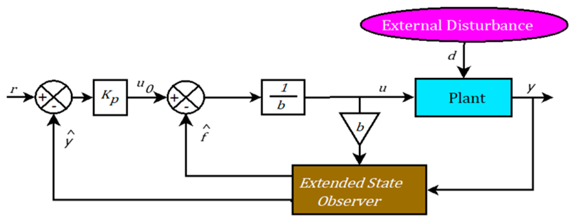
Lastly, the rotor voltages, or control law, are provided by:
2.2. Model of Optimization and Fitness Function
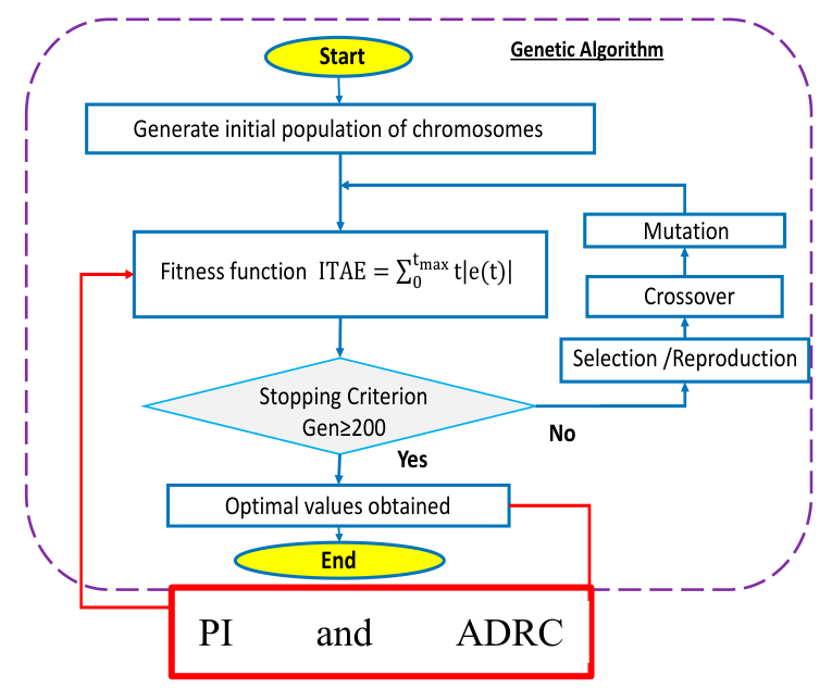
Properly tuned controllers give better performances and minimize the sys; a tuning for PI is not an easy task because it is related for model’s characters, at that work we implement the genetic algorithm to locate the two PI and ADRC optimal parameters .
In comparison to traditional control methods, a fitness function is selected for reduce response time, overshoot, integral time absolute error, and improve disturbance rejection.
The genetic algorithm is among the most popular employed optimization approaches. It may be applied to a variety of optimization issues, particularly those that call for approximations and modelling uncertainty [25,26]. John Holland developed the GA in 1975 as a method to solving optimization problems by examining adaptation in both artificial and natural systems. It is based on a heuristic approach. At each stage, individuals of the present population are chosen by a genetic algorithm to become parents and give birth to the offspring of the following generation. Two fundamental principles are applied in order to generate a future generation from the current one. According to crossover regulations, two parents are combined to create offspring. Based on to mutation regulations, each parent is randomly altered to generate children. According to crossover regulations, two parents are combined to create offspring. According to mutation regulations, each parent is randomly altered for generate children. Without a necessity for actual testing, the GA can be used in a simulation environment that simulates the behavior of wind turbines, enabling quick iteration and optimization. The genetic algorithm created by WECS is depicted in the flowchart in Figure. In our optimization design method, the GA takes into account the characteristics for the PI and ADRC controllers (Kp, Ki). Each of these parameters is programmed, copied, and assessed separately, taking into consideration the fitness of each parameter's function. Individuals are joined and the cycle of examination is maintained as a new generation is generated, only the selected until a method offers an optimal solution for a system with a best fitness function [27,28].
Figure 3.
The genetic algorithm flowchart.
2.3. Battery Energy Storage System Integration and Control
A battery is connected in parallel for a rotor-side DC link through a bidirectional buck-boost converter.
This arrangement allows both charging and discharging modes depending on a power balance between wind generation and load requirements. A buck-boost converter interfaces the lower-voltage battery with the higher-voltage DC bus and enables voltage regulation and current shaping. injects power into the rotor circuit to maintain excitation. During high wind or low load, excess power is absorbed by the battery, thus maintaining rotor-side stability and preventing over-voltage. If the state of charge is less than 20% we cutt of the wind power. The flowchart algorithm of a battery management system is described at Figure 4.
3. Results
A proposed Simulink/Matlab control system is summarised in Figure 5. Table 1 display an DFIG and WT parameters [29,30].
Figure 6 shows the simulation circumstances. The load changes by +150% at t = 10 s and by -50% at t = 22 s. The speed fluctuates from 115 rad/s to 145 rad/s, established at t = 13 s. To compare a performance for a tuned ADRC and a standard ADRC, we offer their control settings in Table 2, which are referenced in Table 4. The genetic algorithm configuration for this investigation is shown in Table 3.

Table 3.
The GA technique's input variables.
| Algorithm’s optimization | Parameters | Values |
| Genetic Algorithm (GA) | Generation | 200 |
| Population size N | 50 | |
| Reduced bound | [0 2000] | |
| Selection process | Stochastic uniform | |
| Elite count | 0.08 |
Table 4.
Comparing the three utilised controllers numerically.
| Approach | D% | ITAE | ITAE | ITAE | ITAE |
| ADRC | 14% | 2.6807 | 53.3680 | 147323 | 258.1098 |
| GA tuned ADRC | 15% | 0.5549 | 6.8077 | 18.9588 | 49.879 |
Figure 7, Figure 8 and Figure 9 display the simulation results of the ADRC and the GA-Tuned ADRC with the independent DFIG-based WT. The stator voltage performances of the two controllers are compared in Figure 7. Figure 7-a displays the direct voltage Vsd, while Figure 7-b displays the quadratic voltage Vsq.
For compare a two controllers' performances, the overshoot reaction time and tracking errors are presented in the same figure. Although there is a slight increase in overshoot, it is evident that the GA optimised controller produces better results in response time and tracking errors. As shown in figure 8, the three comparative important points are at t = 10, 13, and 22 seconds when we alter a rotor speed and load value. The inner loop rotor currents are shown in both the direct and quadratic axes in Figure 9. Because each inner loop has its own reference, we only display the GA-tuned ADRC performances here.
Here are the results of testing the proposed control approach using Simulink/Matlab and the dSPACE1104 on a DFIG-based WECS testbed. Figure 10 displays the testbed for the independent DFIG-based WECS.
To test our suggested controller, we will compare two controllers: the traditional ADRC and the GA-tuned ADRC. An experimental settings were comparable to the simulated conditions shown in figure 5.
Figure 10, Figure 11, Figure 12 and Figure 13 present the experimental results of our controller with the stand alone DFIG based WT.
The following figures illustrate the battery voltage, load voltage, battery current along with its reference, and finally a state of charge (SOC) for a battery. It can be observed that the battery current closely tracks its reference signal, demonstrating an effectiveness for an applied current control strategy. The load voltage shows some variation during dynamic operating conditions, particularly in response to changes in wind speed and load demands.
Importantly, a state for charge remains within a safe and controlled range between 60% and 85%, thanks to the battery management algorithm that is activated after 5 seconds of simulation time. This algorithm plays a critical role in regulating charge and discharge operations to maintain system stability.
Additionally, the SOC profile clearly shows rapid charging behavior between 0% and 20%, which occurs during the early phase when excess energy is available. In contrast, a fast discharging phase is evident when the wind speed exceeds 140 rad/s, as the system demands increased rotor support to stabilize output power and maintain load voltage. These results confirm that the proposed control and energy management approach successfully coordinates energy flow between the DFIG rotor and the battery storage, ensuring voltage stability and efficient use of storage capacity.
Finally, table 5 present a comparative study between the two experimental tests with the two controllers respectively. The overshoot has increased a little from simulation 15% to 25%.
Figure 11 displays the stator voltage components experimental responses and squared under both the suggested GA-optimized ADRC controllers and the traditional ADRC. Both controllers properly set the reference voltage at the start of the experiment. However, notable variations are seen during wind speed and load disturbances that happen at 11, 15, and 23 seconds. Before achieving the steady-state value, the conventional ADRC shows observable overshoots, undershoots, and prolonged oscillatory transients. The GA-ADRC, on the other hand, significantly reduces these oscillations and offers quicker voltage recovery along with better tracking precision. By using the Genetic Algorithm to optimize the controller's parameters, the Extended State Observer (ESO) can be tuned more effectively, improving disturbance compensation, voltage regulation, and robustness against external disturbances and parameter uncertainties.
An experimental development of the rotor direct-axis current is shown in Figure 12. The measured current with the traditional ADRC technique shows sluggish convergence and comparatively substantial tracking errors under transient operating conditions, especially following abrupt changes in wind speed. On the other hand, the current tracking capability is greatly enhanced by the GA-optimized ADRC. Throughout the experiment, the overshoot and settling time are significantly decreased, and the measured current closely tracks its reference. The Genetic Algorithm effectively finds controller parameters that can reduce the impact of nonlinear disturbances and enhance the overall dynamic capacity for DFIG system, as demonstrated by a smoother dynamic response produced by the optimised controller.
The experimental responses of the quadrature-axis rotor current are contrasted in Figure 12. During transient occurrences, the conventional ADRC shows significant differences between the measured and reference currents, suggesting a weak ability to reject disturbances. By contrast, across the whole working period, the proposed GA-ADRC achieves significantly tighter agreement between the reference and measured signals. When wind speed and load disturbances occur, the controller quickly returns to the intended operating position and significantly reduces current oscillations. These outcomes show how well the optimised ADRC works to sustain steady electromagnetic torque production while increasing current regulation accuracy.
Figure 11.
The stator voltages - experimental results.
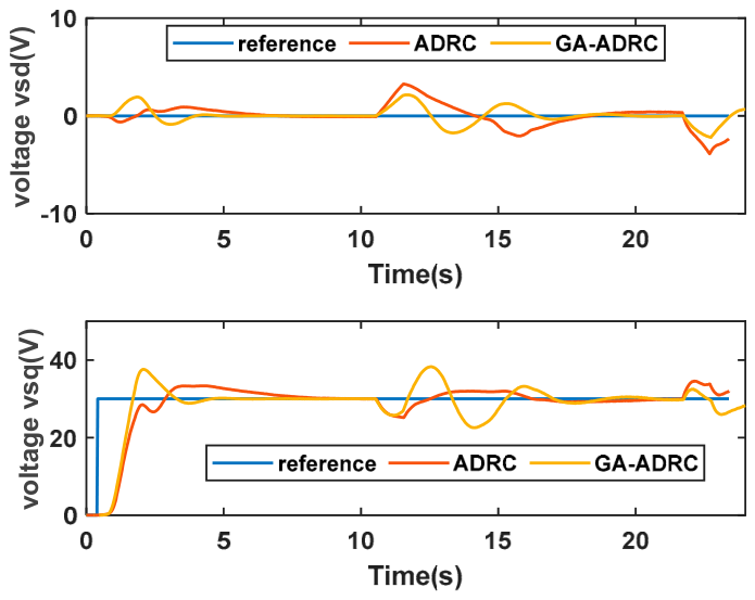
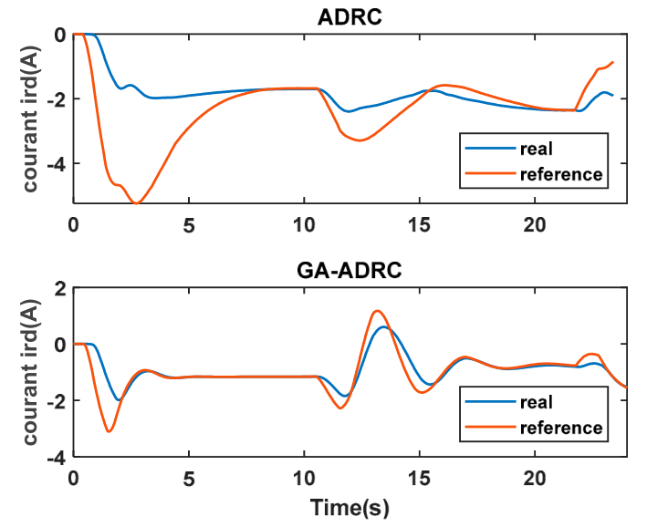
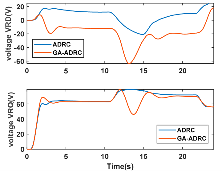
The experimental results show that both control algorithms are robust to variations in speed and load and perform well under nominal conditions. But when it comes to tracking error and response time, the GA-tuned ADRC performs noticeably better than the other. The rotor currents closely track their reference with a short response time, as shown by the previously noted critical points at t = 10, 13, and 22 seconds. Table 4 displays a numerical comparison of the overshoot and integral time absolute errors of the two controllers. With a small increase in overshoot, the GA-tuned ADRC outperforms the non-optimized ADRC. Finally, we display the rotor voltage signals in Figure 13, where it is clear that they are acceptable and fall within the DFIG nominal values.
Figure 12.
The rotor currents - experimental results.
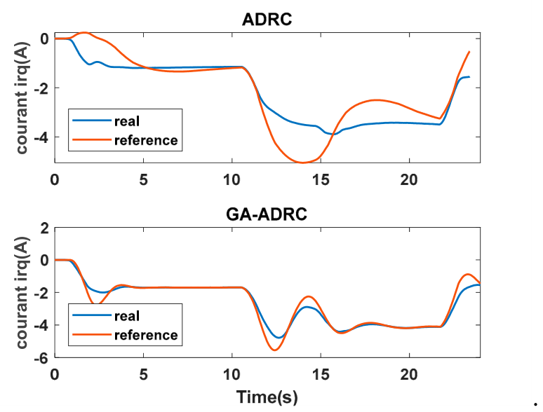
Figure 13.
The experimental findings on the rotor voltages.
All things considered, the experimental findings unequivocally show that the suggested GA-optimized ADRC is superior to the traditional ADRC approach. The optimised controller offers quicker transient response, less overshoot, fewer oscillations, better reference tracking accuracy, and increased resilience under all examined operating situations, including wind speed fluctuations and nonlinear load disturbances. Additionally, while preserving stable rotor current dynamics and lowering the control effort needed by the rotor-side converter, the optimised controller greatly enhances voltage regulation. The efficiency and usefulness of the suggested control method for freestanding DFIG-based wind energy conversion devices are further supported by the strong agreement between simulation and experimental results.
The experimental evolution of battery State of Charge (SOC) under various operating situations is shown in the figure 14. The battery management algorithm efficiently controls a charging and discharging procedures based on a load demand and available wind power. Both excessive charging and deep discharge are avoided by keeping the SOC within a safe operating range of roughly 50% to 82%. The battery is charged during times of excess power generation, which causes the SOC to gradually rise. On the other hand, the battery discharges to maintain the standalone DFIG-based WECS during power shortfalls brought on by decreased wind speed or increased load demand, resulting in a regulated decrease in SOC. These findings demonstrate that the suggested battery management approach effectively maintains battery health while guaranteeing steady system performance and constant power availability.
The discharged battery capacity during the experimental test is shown in Figure 15. The battery management algorithm's commands for charging and discharging cycles cause the discharged capacity to fluctuate on a regular basis. Stable battery functioning without unusual fluctuations or sudden energy exchanges is demonstrated by the discharged capacity's smooth and repeating progression. This behaviour demonstrates that the suggested controller successfully prevents excessive battery stress while balancing the energy flow between the battery and the wind energy conversion equipment.
The experimental battery terminal voltage for the whole working time is displayed in Figure 16. The battery voltage barely slightly fluctuates around its nominal value of roughly 12.5 V despite numerous cycles of charging and draining. This steady voltage profile shows how well the suggested battery management algorithm maintains safe battery operating conditions. Additionally, the lack of notable voltage drops indicates that the battery is not overcharged or severely drained while the system is operating, improving an overall dependability and lifespan for energy storage system.
The experimental DC-link voltage provided by a bidirectional buck-boost converter is shown at Figure 17. Throughout a experiment, there are multiple charging and discharging transitions, yet the DC-link voltage stays well controlled within a constrained operational range. A suggested control method quickly returns the intended operating point without excessive oscillations, while small voltage variations are seen right away following changes in operating conditions. Continuous power transmission and dependable converter operation are ensured by the stable DC-link voltage, which validates the correct coordination between a battery energy storage system, a bidirectional converter, and the DFIG control scheme.
The reference and measured battery currents produced by the suggested battery management algorithm are contrasted in Figure X. Throughout the entire experiment, there was a very tight agreement between the two signals, showing outstanding current tracking performance. While negative current values indicate battery discharge phases that send energy to the independent DFIG-based wind energy conversion system, positive current values correspond to battery charging periods. The recommended current control system's effectiveness is demonstrated by the seamless transition between charging and discharging modes, which is free of excessive overshoot or oscillations. Additionally, the magnified view validates the excellent tracking accuracy attained during transient situations, confirming the battery controller's dynamic performance as well as the efficacy of the energy management approach that was put in place.
All things considered, the experimental findings show how successful the suggested Battery Energy Storage System (BESS) paried with the independent DFIG-based WECS is. While keeping a battery's state of charge within safe operating bounds, a battery management algorithm effectively coordinates the charging and discharging procedures in accordance with the load demand and available wind power. Furthermore, the robustness and dependability of the suggested energy management technique are confirmed by the steady battery voltage, well-regulated DC-link voltage, smooth discharged capacity evolution, and precise battery current tracking. These findings confirm that it is feasible for improve a stability, power quality, and operational continuity for standalone wind energy conversion systems by combining a BESS with a GA-optimized ADRC controller.
By calculating the integral time absolute error numerically, we verify the superiority of the GA-ADRC in Table 5.
4. Discussion
The resulting modelling and practical results show how well the suggested GA-optimized ADRC ensures reliable voltage regulation for the independent DFIG-based wind energy conversion system under nonlinear load situations and varying wind speeds. Because of the ADRC's active compensation of internal and external disturbances and the Genetic Algorithm's optimal parameter tuning, the suggested strategy outperforms conventional PI control in terms for dynamic response, overshoot reduction, and disturbance rejection capabilities.
Additionally, controlling the level of charge within safe operating limits and preserving system stability are greatly aided by the integration of the Battery Energy Storage System (BESS) and the related battery management algorithm. These outcomes show the feasibility of a suggested technique through real-time implementation on a dSPACE 1104 platform and are in line with other research emphasizing the benefits of ADRC-based approaches. Future research will concentrate on expanding a suggested framework to include advanced artificial intelligence-based energy management techniques and hybrid renewable energy systems.
5. Conclusions
At that work, we created and verified a GA-optimized Active Disturbance Rejection Controller (ADRC) for voltage control in a stand-alone DFIG-based wind energy conversion system that operates with fluctuating wind speeds and nonlinear load conditions. By incorporating a battery management algorithm that guarantees steady functioning for a energy storage system within specified SOC limits, the suggested control method was further improved.
Simulation results obtained in the MATLAB/Simulink environment, along with experimental validation employing a dSPACE 1104 real-time platform, confirm the superior robustness and dynamic performance of the GA-tuned ADRC when compared to conventional PI control. The controller demonstrates excellent current tracking, effective voltage regulation, and coordinated energy flow with the rotor-connected battery under diverse operating conditions.
The experimental results are in close agreement with a simulations and validate a practical feasibility for a proposed control system. In particular, the integration of the battery management algorithm successfully maintains the state of charge within the desired range, contributing to both system reliability and energy efficiency. Overall, this work demonstrates that the GA-tuned ADRC, combined with intelligent battery management, is a viable and effective solution for standalone DFIG-based wind turbine applications.
Author Contributions
Conceptualization, N.M. and E.A.; methodology, N.M.; software, N.M.; validation, N.M., C.B. and M.C.; formal analysis, N.M.; investigation, N.M.; resources, E.A. and C.B.; data curation, N.M.; writing—original draft preparation, N.M.; writing—review and editing, M.C., C.B. and E.A.; visualization, N.M.; supervision, C.B. and E.A. All authors have read and agreed to the published version of the manuscript.
Funding
Please add: This research received no external funding.
Institutional Review Board Statement
Not applicable.
Informed Consent Statement
Not applicable.
Data Availability Statement
The data presented in this study are available from the corresponding author upon reasonable request.
Acknowledgments
The authors also acknowledge the LASTIMI Laboratory, Higher School of Technology, Mohammed V University in Rabat, Morocco, for its scientific support throughout this work.
Conflicts of Interest
The authors declare no conflicts of interest. The funders had no role in the design of the study; in the collection, analyses, or interpretation of data; in the writing of the manuscript; or in the decision to publish the results.
Abbreviations
The following abbreviations are used in this manuscript:
| ADRC | Active Disturbance Rejection Control |
| BESS | Battery Energy Storage System |
| DFIG | Doubly Fed Induction Generator |
| ESO | Extended State Observer |
| GA | Genetic Algorithm |
| GSC | Grid-Side Converter |
| MPPT | Maximum Power Point Tracking |
| PI | Proportional–Integral |
| PWM | Pulse Width Modulation |
| RSC | Rotor-Side Converter |
| SOC | State of Charge |
| WECS | Wind Energy Conversion System |
| dSPACE | Digital Signal Processing and Control Engineering Platform |
References
- Hamdan, I.; Youssef, M.M.M.; Noureldeen, O. Influence of interval type-2 fuzzy control approach for a grid-interconnected doubly-fed induction generator driven by wind energy turbines in variable-speed system. SN Appl. Sci. 2023, 5, 25. [Google Scholar] [CrossRef]
- Benbouhenni, H.; Bizon, N.; Colak, I.; et al. Controlling the energies of the single-rotor large wind turbine system using a new controller. Sci. Rep. 2025, vol. 15, art. 3191. [Google Scholar]
- Abo-Khalil, G.; Alobaid, M. Optimized Control for PMSG Wind Turbine Systems under Unbalanced and Distorted Grid Voltage Scenarios. Sustainability 2023, vol. 15(no 12), 9552. [Google Scholar] [CrossRef]
- Labdai, S.; Chrifi-Alaoui, L.; Nezli, L.; Hemici, B.; Bussy, P. « Implementation of the Adaptive Neural networks Backstepping controller for a stand-alone DFIG based WECS », in 2021 9th International Conference on Systems and Control (ICSC), Caen, France: IEEE, nov. 2021, p. 529-535. IEEE. [CrossRef]
- André, S.; Silva, F.; Pinto, S.; Miguens, P. Novel Incremental Conductance Feedback Method with Integral Compensator for Maximum Power Point Tracking: A Comparison Using Hardware in the Loop. Appl. Sci. 2023, vol. 13(no 7), 4082. [Google Scholar] [CrossRef]
- Aissaoui; Elmouhi, N.; Essadki, A.; Elaimani, H. Fault tolerant control for DFIG wind turbine controlled by ADRC and optimized by genetic algorithm. Int. J. Power Electron. Drive Syst. 2023, vol. 14(no. 3), 1382–1393. [Google Scholar] [CrossRef]
- Bouchiba, N.; Barkia, A.; Sallem, S.; Chrifi-Alaoui, L.; Drid, S.; Kammoun, M. B. A. Implementation and comparative study of control strategies for an isolated DFIG based WECS. Eur. Phys. J. Plus 2017, vol. 132, no 10. [Google Scholar] [CrossRef]
- Achar; Djerri, Y.; Benbouhenni, H. Modified vector-controlled DFIG wind energy system using robust model predictive rotor current control. Arab. J. Sci. Eng. 2024, 1–25. [Google Scholar] [CrossRef]
- Bounar, N.; Labdai, S.; Boulkroune, A. PSO–GSA based fuzzy sliding mode controller for DFIG-based wind turbine. ISA Trans. 2019, vol. 85, 177-188. [Google Scholar] [CrossRef] [PubMed]
- Zou, Y.; Bai, X.; Li, L.; Sheng, Y.; Ye, G.; Jian, Q. Variable pitch fractional-order model-assisted active disturbance rejection controller for wind turbine active power regulation. Electr. Power Syst. Res. 2024, vol. 233, 110424. [Google Scholar] [CrossRef]
- Mrabet, N.; Benzazah, C.; El Akkary, A.; Ennaciri, Y.; Lahlouh, I. Maximum power optimization of a direct-drive wind turbine connected to PMSG using multi-objective genetic algorithm. IJAPE 2024, vol. 13(no 2), 453. [Google Scholar] [CrossRef]
- Labdai, S.; Hemici, B.; Nezli, L.; Bounar, N.; Boulkroune, A.; Chrifi-Alaoui, L. « Control of a DFIG Based WECS with Optimized PI controllers via a duplicate PSO algorithm ». 2019 International Conference on Control, Automation and Diagnosis (ICCAD), Grenoble, France, juill. 2019; IEEE; p. 1-6. [Google Scholar] [CrossRef]
- Mrabet, N.; et al. Enhancing Wind Energy Conversion Efficiency: A Novel MPPT Approach Using P&O with ADRC Controllers versus PI Controllers with Kp and Ki Optimization via Genetic Algorithm and Ant Colony Optimization. Clean. Energy Syst. 2024, vol. 9, 100159. [Google Scholar] [CrossRef]
- Mrabet, N.; Benzazah, C.; El Akkary, A.; Chakib, M.; Lahlouh, I. « Fine-Tuning PI Controller Parameters for an Efficient Wind Energy Extraction System through Mean Squared Error (MSE): A Control System based on Ant Colony Optimization for Maximum Power Point Tracking (MPPT) », in 2024 Mediterranean Smart Cities Conference (MSCC); IEEE: Martil - Tetuan, Morocco, 2024; p. 1-6. [Google Scholar] [CrossRef]
- Labdai, S.; Chrifi-Alaoui, L.; Delahoche, L.; Marhic, B.; Bussy, P. « Hybrid interior point method and genetic algorithm for parameter estimation of three-phase induction motor », in 2021 9th International Renewable and Sustainable Energy Conference (IRSEC). IEEE, Morocco, nov. 2021; p. 1-7. [Google Scholar] [CrossRef]
- Mrabet, N.; Benzazah, C.; El Akkary, A.; Sefiani, N. Multi-Objective Ant Colony Optimization for Enhancing the Maximum Power of Variable-Speed Wind Turbines Based on PMSG. IRECON 2023, vol. 11(no 5), 195. [Google Scholar] [CrossRef]
- Bouchiba, N.; Barkia, A.; Chrifi-Alaoui, L.; Drid, S.; Sallem, S.; Kammoun, M. B. A. Real-time integration of control strategies for an isolated DFIG-based WECS. Eur. Phys. J. Plus 2017, vol. 132, no 8. [Google Scholar] [CrossRef]
- Ali, I. M.; Mohamed, H. R. A. Improved P&O MPPT algorithm with efficient open-circuit voltage estimation for two-stage grid-integrated PV system under realistic solar radiation. Int. J. Electr. Power Energy Syst. 2022, vol. 137, 107805. [Google Scholar] [CrossRef]
- Mossa, M.A.; Gam, O.; Bianchi, N. Dynamic Performance Enhancement of a Renewable Energy System for Grid Connection and Stand-Alone Operation with Battery Storage. Energies 2022, 15, 1002. [Google Scholar] [CrossRef]
- Hachana, O.; Meghni, B.; Benamor, A.; Toumi, I. Efficient PMSG Wind Turbine with Energy Storage System Control Based Shuffled Complex Evolution Optimizer. ISA Trans. 2022. [Google Scholar] [CrossRef] [PubMed]
- Hadoune, A.; et al. Optimizing Direct Power Control of DFIG-Based WECS under Actual Wind Conditions Using a Super-Twisting Algorithm. Front. Energy Res. 2023. [Google Scholar] [CrossRef]
- Watil, A.; El Magri, A.; Raihani, A.; Lajouad, R.; Giri, F. An Adaptive Nonlinear Observer for Sensorless Wind Energy Conversion System with PMSG. Control Eng. Pract. 2020, 98, 104356. [Google Scholar] [CrossRef]
- Chojaa, H.; Derouich, A.; Zamzoum, O.; El Idrissi, A. Robust Control System for DFIG-Based WECS and Energy Storage in Real Wind Conditions. EAI Endorsed Trans. Energy Web 2024, 11. [CrossRef]
- Singh, P.; Arora, K.; Rathore, U.C.; Yang, E.; Joshi, G.P.; Son, K.C. Performance Evaluation of Grid-Connected DFIG-Based WECS with Battery Energy Storage System under Wind Alterations Using FOPID Controller for Rotor-Side Converter. Mathematics 2023, 11, 2100. [Google Scholar] [CrossRef]
- Chojaa, H.; Derouich, A.; Zamzoum, O.; Watil, A. Robust Control of DFIG-Based WECS Integrating an Energy Storage System under Real Wind Conditions. IEEE Access 2023. [Google Scholar] [CrossRef]
- Chojaa, H.; Derouich, A.; Zamzoum, O.; Watil, A. Robust Control of DFIG-Based WECS Integrating an Energy Storage System with Intelligent MPPT under a Real Wind Profile. IEEE Access 2023, 11. [Google Scholar] [CrossRef]
- Chojaa, H.; Derouich, A.; Zamzoum, O.; Watil, A. Robust Control of DFIG-Based WECS Integrating an Energy Storage System with Intelligent MPPT under a Real Wind Profile. IEEE Access 2023, 11. [Google Scholar] [CrossRef]
- Phung, B.N.; Wu, Y.-K.; Pham, M.-H. Coordinated Frequency Regulation between DFIG-VSWTs and BESS Hybrid Systems. Energies 2024, 17, 3099. [Google Scholar] [CrossRef]
- Hamdan, I.; Youssef, M.M.M.; Noureldeen, O. Influence of Interval Type-2 Fuzzy Control Approach for a Grid-Interconnected Doubly-Fed Induction Generator Driven by Wind Energy Turbines in Variable-Speed System. SN Appl. Sci. 2023, 5, 25. [Google Scholar] [CrossRef]
- Benbouhenni, H.; Mehedi, F.; Soufiane, L. New Direct Power Synergetic-SMC Technique Based PWM for DFIG Integrated to a Variable-Speed Dual-Rotor Wind Power System. Automatika 2022, 63, 718–731. [Google Scholar] [CrossRef]
Figure 1.
The suggested setup for the independent DFIG-based WT.
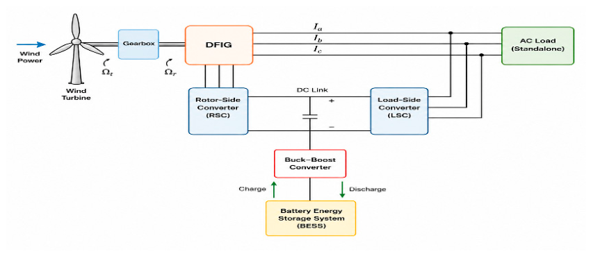
Figure 4.
Operation strategy of the power system.
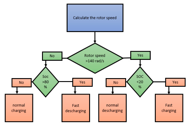
Figure 5.
The independent DFIG Control approach.
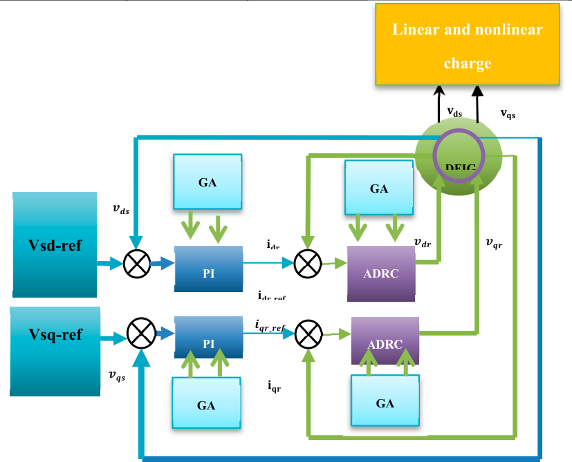
Figure 6.
Simulation conditions.
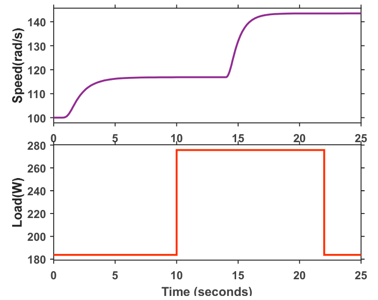
Figure 7.
ADRC and GA-tuned ADRC stator voltages.
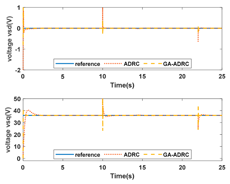
Figure 8.
The GA-tuned ADRC rotor currents.
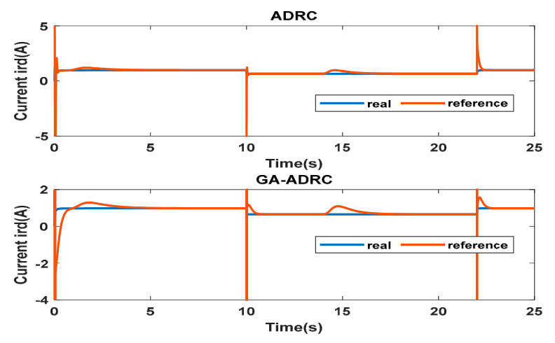
Figure 9.
The rotor voltages with GA-tuned ADRC.
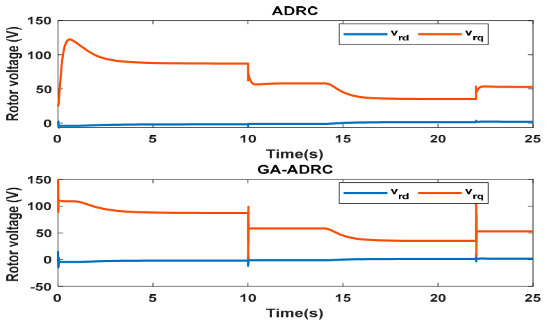
Figure 10.
An experimental testbed for DFIG.
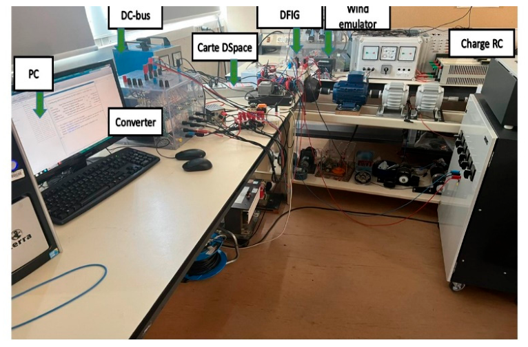
Figure 14.
Battery SOC.
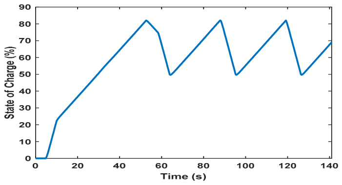
Figure 15.
DFIG Speed.
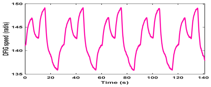
Figure 16.
Battery Voltage (V).
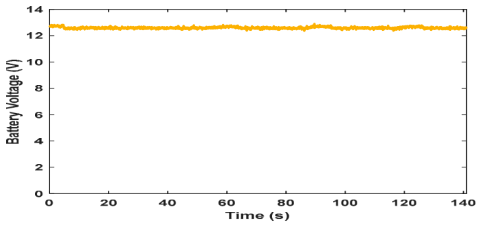
Figure 17.
Battery Load.
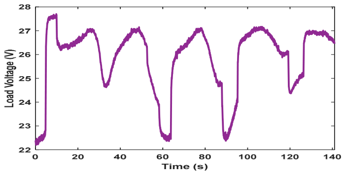
Figure 18.
Battery Current.
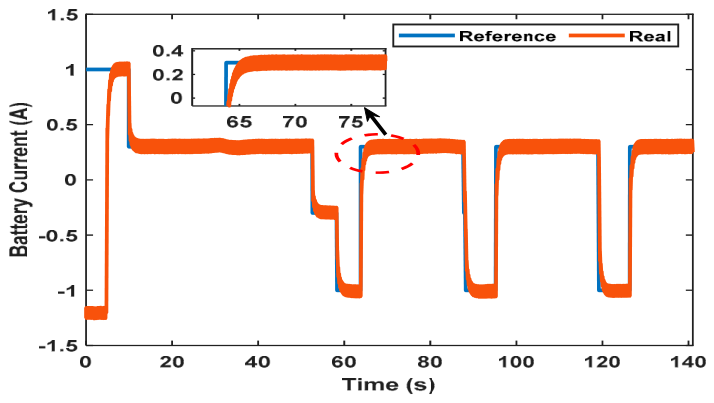
Table 1.
DFIG specifications.
| Stator resistance Rs | 4.9 | Nominal power | 1.5 |
| Rotor resistance Rr | 4.0 | Total inertia | 0.022 |
| Stator inductance Ls | 0.24 | Damping | 0.01 |
| Rotor inductance Lr | 0.24 | Nominal speed | 157 |
| Mutual inductance M | 0.2 | Poles | 2 |
Table 2.
The GA-ADRC and ADRC parameters.
| Parameter | ADRC | GA-ADRC |
| 5 | 18 | |
| 10 | 241 | |
| 5 | 3 | |
| 10 | 468 | |
| 2 | 22 | |
| 6 | 11 | |
| 36 | 9 | |
| 2 | 22 | |
| 6 | 4 | |
| 36 | 19 |
Table 5.
A numerical comparison of the three controllers in use.
| Approach | D% | ITAE | ITAE | ITAE | ITAE |
| ADRC | 11% | 16..9005 | 12.7875 | 58.6196 | 64.0698 |
| GA tuned ADRC | 25% | 1.6687 | 4.4414 | 35.3989 | 60.5450 |
Disclaimer/Publisher’s Note: The statements, opinions and data contained in all publications are solely those of the individual author(s) and contributor(s) and not of MDPI and/or the editor(s). MDPI and/or the editor(s) disclaim responsibility for any injury to people or property resulting from any ideas, methods, instructions or products referred to in the content. |
© 2026 by the authors. Licensee MDPI, Basel, Switzerland. This article is an open access article distributed under the terms and conditions of the Creative Commons Attribution (CC BY) license.
Copyright: This open access article is published under a Creative Commons CC BY 4.0 license, which permit the free download, distribution, and reuse, provided that the author and preprint are cited in any reuse.


