

Submitted:
24 July 2026
Posted:
27 July 2026
You are already at the latest version
Abstract
Abstract: The widespread application of fly ash ceramsite lightweight aggregate in high-performance concrete is restricted by its inherent defects, including high porosity, high water absorption rate and weak interfacial transition zone (ITZ). In this study, a high-performance surface strengthening coating composed of micro-namo silica fume and modified acrylate emulsion was designed and prepared, aiming to modify its macroscopic mechanical and durability properties. The results show that, the coating treatment improved 28‑day compressive, flexural‑tensile, and axial tensile strengths by 21.2%, 16.0%, and 20.6%, respectively, along with the elastic modulus and ultimate tensile strain. The coated concrete achieved an impermeability grade exceeding W14, retained over 85% of relative dynamic elastic modulus after 150 freeze‑thaw cycles, and maintained compressive strength above 90.0% after 20 wetting–drying cycles, with a corresponding relative dynamic elastic modulus of 67.24%. Microstructural observation, pore parameter analysis, and microzone mechanical testing were performed to reveal the underlying mechanisms. The performance improvement is mainly attributed to the strengthening of the traditionally weak interfacial transition zone (ITZ). Additionally, the coating refines the pore structure, stabilizes its distribution, and acts as a physical barrier, further enhancing resistance to freeze‑thaw and wetting–drying cycles.
Keywords:
fly ash ceramsite concrete
; surface coating
; interfacial transition zone
; pore distribution
1. Introduction
With the development of society, new requirements have been put forward for concrete in the construction industry: concrete should not only possess high strength and excellent durability, but also have low self-weight. The application of high-strength lightweight concrete (HSLC) in the construction of super high-rise buildings, long-span bridges and other engineering structures yields superior technical and economic benefits [1]. HSLC has become one of the development trends of global concrete technology. Fly ash can be processed into lightweight aggregate for concrete through a series of special processes. Compared with ordinary concrete, fly ash ceramsite concrete has the advantages of low self-weight, excellent seismic performance, low thermal conductivity and superior thermal insulation performance. In addition, it can utilize industrial wastes, reduce pollution, conserve resources, and greatly alleviate the environmental pressure caused by fly ash solid wastes [2]. However, fly ash ceramsite also has its shortcomings. It is characterized by low apparent density and high water absorption rate, with a 1-hour water absorption rate of 6%~15% and a saturated water absorption rate of over 30% [3,4]. When concrete is mixed with fly ash ceramsite, problems such as stratification, segregation, rapid slump loss and pump blockage are prone to occur under normal pumping construction conditions [5]. In addition, fly ash ceramsite is lightweight, porous and hollow inside, with a cylinder crushing strength of usually only 4~10 MPa. This leads to splitting and crushing at the weak surface when it is subjected to compression as lightweight aggregate in concrete structures, which greatly restricts the development of the compressive strength of concrete and limits its application in concrete engineering.
In order to improve the compressive strength and durability of fly ash ceramsite concrete, in-depth studies have been conducted at home and abroad. H. Al-Khaiat [6] investigated the compressive strength of lightweight aggregate and concluded that the strength of lightweight aggregate concrete is mainly determined by the strength of aggregate. With the increase of concrete curing age, the concrete strength does not increase linearly, and it basically stops increasing when the concrete strength reaches the cylinder crushing strength of ceramsite D. S. Babu [7,8] found that under the action of external loads, the fracture mode of ceramsite concrete is mainly characterized by crack propagation through ceramsite particles. Simply reducing the water-cement ratio cannot significantly improve the compressive strength of concrete, but increasing the strength of ceramsite can remarkably enhance the concrete strength. The study also revealed that the lower the porosity and the higher the particle density of ceramsite, the higher the strength of the prepared concrete. Some studies have shown that reducing the water absorption rate of fly ash ceramsite can significantly improve the strength of fly ash ceramsite concrete. A spherical lightweight aggregate with low water absorption, high particle strength and stable performance has been produced through a special manufacturing process [9,10]. Under the optimal conditions, the resulting ceramsite exhibited low apparent and bulk densities (0.86 and 0.46 kg/m3), high compressive strength (1.76 MPa), low water absorption (0.96%), and low toxicity leaching, with uniform internal pores and crystalline phases of anorthite and mullite, demonstrating a feasible route for harmless utilization of these industrial solid wastes [11].
The pozzolanic reaction of fly ash ceramsite mainly occurs in the ITZ adjacent to the surface layer and the cement paste matrix. The loose and porous surface of fly ash ceramsite results in weak physical interlocking and chemical bonding with cement paste, leading to the formation of an ITZ with inferior performance [12,13]. Existing studies on the micromechanical properties of the ITZ in ceramsite concrete are insufficient, most of which are limited to qualitative descriptions through scanning electron microscopy (SEM) observations and lack quantitative analysis of the micromechanical properties of the ITZ. In contrast, the research on the micromechanical properties of the ITZ in ordinary concrete is more in-depth, and nanoindentation technology or microhardness testers are commonly used to test the micromechanical properties of hydration products in the ITZ, such as elastic modulus, hardness and creep modulus [14,15,16,17]. As an internal “microstructural defect” in concrete, the ITZ is the primary region for stress concentration and microcrack initiation, which severely deteriorates the macroscopic mechanical properties and long-term durability of concrete, and poses severe challenges to its application in buildings with high durability requirements [18]. Improving aggregate properties or optimizing the aggregate-paste ITZ is the key to enhancing the comprehensive performance of concrete. Most existing studies focus on improving the performance of cement paste by optimizing the composition of the cementitious system, introducing active admixtures or chemical admixtures [19], or enhancing the intrinsic strength of aggregates by improving their production processes [20]. However, these methods often have limitations or are excessively costly for formed fly ash ceramsite aggregates with inherent performance deficiencies. In comparison, surface treatment of fly ash ceramsite is a more direct, economical and efficient reinforcement approach. Surface coating technology aims to construct a high-performance “artificial shell” on the surface of fly ash ceramsite, which plays three roles: firstly, it physically seals the open pores on the surface of fly ash ceramsite, reduces its water absorption rate and prevents excessive moisture migration; secondly, it strengthens the mechanical properties of the fly ash ceramsite surface layer to compensate for its loose surface defects; thirdly, it acts as a “bridge” between fly ash ceramsite and paste, improving the microstructure of the interfacial zone and enhancing the bonding force [21,22,23]. At present, the research on coating reinforcement of fly ash ceramsite lightweight aggregate mostly focuses on spraying a layer of waterproof coatings such as paraffin or polystyrene emulsion on the outer surface, and mainly investigates the effect of coatings on mechanical properties. However, there is still a lack of systematic experimental research and mechanism interpretation on the synergistic improvement mechanism of inorganic composite paste coatings on the macroscopic mechanical properties and multi-dimensional durability properties of concrete, including impermeability, frost resistance and dry-wet cycle resistance.
Based on the concept of improving material properties through coating technology, an innovative composite surface strengthening coating system composed of ordinary Portland cement, ultra-fine silica fume and polymer acrylic emulsion (PAE) was designed in this study. In this paper, fly ash ceramsite was subjected to accurately metered coating wrapping treatment, and the comprehensive improvement effects of the coating on the macroscopic mechanical properties (compressive strength, tensile strength, flexural strength) and key durability properties (impermeability, frost resistance, dry-wet cycle resistance) of fly ash ceramsite lightweight aggregate concrete were systematically evaluated. Through comprehensively employing optical microscopy, hardened concrete air void structure analyzer and microhardness tester, the enhancement mechanism of the coating on the properties of fly ash ceramsite lightweight aggregate concrete was further revealed from multiple micro-scales including interfacial structure evolution, quantitative characterization of pore structure parameters and microzone property changes, which provides a complete technical solution and an innovative theoretical basis for the wide application of fly ash ceramsite lightweight aggregate.
2. Materials and Experimental Proposal
2.1. Raw Materials and Proportion
2.1.1. Raw Materials
Coarse aggregate: fly ash ceramsite with two nominal particle size grades of 5~10 mm and 10~20 mm.
Figure 1.
Partial size grades of fly ash ceramsite.
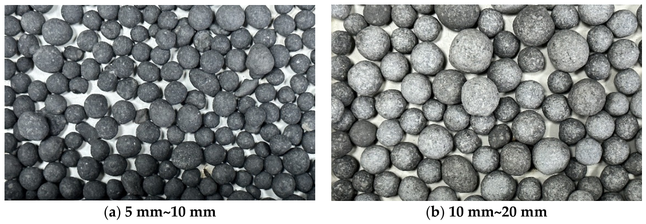
The test results of its basic physical properties are shown in Table 1. The data show that the bulk density of this fly ash ceramsite is 1095 kg/m3, which falls into the category of lightweight aggregate; its cylinder crushing strength is 8.9 MPa, which is significantly lower than that of natural stone; the water absorption rate measured by the freeze-drying method is as high as more than 12%, indicating its internal porous and loose physical characteristics, which is also one of the root causes leading to the deterioration of its concrete properties.
Other raw materials for concrete: P·O 42.5 grade cement was used as the cementitious material; the fine aggregate was natural river sand with a fineness modulus of 2.9; a polycarboxylate-based high-performance water reducer was used as the chemical admixture to regulate the workability of fresh concrete.
2.1.2. Concrete Mix Proportions
To systematically investigate the effect of the coating on concrete with different strength grades, three concrete mixes with water-binder ratios of 0.26, 0.33 and 0.40 were designed in this study. Among them, the core comparison groups were the coated concrete (LC-261) and the uncoated concrete (LC-26) with a water-binder ratio of 0.26. All mixes adopted 100% volume replacement of traditional crushed stone with fly ash ceramsite, and the dosage of fly ash ceramsite per cubic meter of concrete was calculated as 670 kg according to the equal volume replacement principle. The two particle size grades of fly ash ceramsite (5~10 mm and 10~20 mm) were compounded at a mass ratio of 1:1 to obtain the minimum bulk void ratio. The specific mix proportions are shown in Table 2.
2.2. Coating and Wrapping
2.2.1. Coating Materials
The modified coating was prepared by compounding cement, silica fume and modified acrylic emulsion. The cement used was P·O 42.5 ordinary Portland cement, whose physical and mechanical properties met the requirements of GB 175-2023 standard.
SF90 grade micro-nano silica fume with a SiO2 content of 92.0% and a specific surface area of not less than 21000 m2/kg was selected. The introduction of silica fume mainly utilizes its extremely fine particle size (average particle size of approximately 0.1 μm) to achieve the micro-aggregate filling effect, thereby reducing the porosity of the coating paste.
PAE is an acrylate copolymer emulsion with a solid content of 40%. PAE serves multiple functions in the coating: its polymer emulsion can demulsify and form a film during the cement hydration process, forming an organic-inorganic interpenetrating network structure, which significantly enhances the crack resistance of the coating; meanwhile, PAE can effectively improve the workability of the paste and enhance the wettability and encapsulation performance on the surface of fly ash ceramsite; furthermore, the PAE film can block capillary pores and reduce the permeability of the coating.
2.2.2. Design of Coating Mix Proportion
The design objective of the coating is to form a protective shell with high strength, compactness, low permeability, excellent adhesion and certain toughness. In the coating design process, the water-binder ratio should be reduced to improve the intrinsic strength of the coating and lower its porosity. The micro-filling effect of silica fume is utilized to refine the pore structure of the coating paste, while the secondary hydration products generated from its pozzolanic reaction enhance the interfacial bond strength and durability. The external addition of PAE polymer emulsion forms a “cement paste-polymer film” composite structure at the microscale. However, excessive addition of either component may alter the wrapping performance of the ceramsite concrete.
Through a series of adjustments and preliminary experiments, the final optimized mix proportion was determined as follows: water-binder ratio of 0.28, cement-to-silica fume mass ratio of 95:5 (internal incorporation), and external addition of 15% modified acrylic emulsion (by mass of the total cementitious materials).
2.2.3. Coating Wrapping
To achieve accurate, controllable and uniform distribution of coating thickness (designed average thickness h=0.1 mm), the empirical wrapping method was abandoned in this study, and a calculation formula for coating dosage was derived based on the geometric characteristics and physical parameters of fly ash ceramsite. The spheroidal fly ash ceramsite was simplified as a spherical model, and the specific surface area of fly ash ceramsite with a single particle size can be expressed as . Furthermore, for a fly ash ceramsite population with a certain mass and particle size distribution, the calculation formula for the total coating wrapping amount mc is:
where,
ρL – Saturated surface dry apparent density of fly ash ceramsite;
Pi -Mass fraction of fly ash ceramsite in a certain particle size range (the i-th grade);
mLi -Mass of fly ash ceramsite in this grade (the i-th grade);
Di – Representative particle size of this grade (the i-th grade).
According to this formula and the screening results of fly ash ceramsite, the dosages of cement, silica fume, PAE and water required per unit mass of fly ash ceramsite can be accurately calculated, ensuring the repeatability of the test and the popularization of the technology.
The wrapping process draws on and improves the SEC [24] (Sand Enveloped with Cement) method, adopting a mixing scheme of pre-wrapping fly ash ceramsite with coating, and the specific process is as follows (Figure 2):
(1) Pre-water saturation: fly ash ceramsite was soaked in clean water for 24 h to make it fully absorb water. This step aims to prevent fly ash ceramsite from absorbing water in the coating paste too quickly in the subsequent “shell-forming” stage, resulting in the loss of paste workability.
(2) Drainage and moisture conditioning: The water-saturated fly ash ceramsite was taken out, drained of free water, and its surface moisture content was precisely controlled within a narrow range of 1%~3% by towel wiping or short-term air drying. A very thin water film exists on the surface of fly ash ceramsite in the saturated surface dry state, which is conducive to the adhesion between fly ash ceramsite and the coating.
(3) Dry mixing for shell formation: The moisture-conditioned fly ash ceramsite and the coating dry material (premix of cement and silica fume) were put into a forced mixer together and dry mixed rapidly for 30 seconds. At this time, the dry cement and silica fume particles adhered quickly and uniformly to the surface of the wet fly ash ceramsite under the action of mechanical force, forming an initial cement-based “dry shell” with a low effective water-binder ratio.
(4) Wet mixing for wrapping: The pre-calculated mixing water (with the surface moisture content of fly ash ceramsite deducted) was mixed evenly with the full amount of PAE emulsion, then added to the mixer at one time and wet mixed continuously for 60 seconds. During this process, water and polymer emulsion fully penetrated and lubricated the formed “dry shell”, and finally formed a uniform, dense and complete coating with good adhesion on the surface of fly ash ceramsite.
The core advantage of this process lies in achieving the maximum and uniform distribution of the coating material on the surface of fly ash ceramsite, forming a tight “mechanical-chemical” bond and realizing the ideal “shell-forming” effect.
2.3. Performance Tests
2.3.1. Mechanical Properties
The tests were conducted in accordance with the Test Code for Hydraulic Concrete (SL/T 352-2020), including cubic compressive strength (150 mm cube), axial compressive strength and static compressive modulus of elasticity (150 mm × 150 mm × 300 mm prism), axial tensile strength and ultimate tensile value, and four-point flexural-tensile strength (100 mm × 100 mm × 400 mm prism). For each test, three replicate measurements were carried out, and the arithmetic mean of the measured values was adopted as the final outcome.
2.3.2. Durability Properties
The impermeability grade was determined by the stepwise pressurization method according to the Test Code for Hydraulic Concrete (SL/T 352-2020), supplemented by the constant water pressure method (0.8MPa, 24h) to measure the average water seepage height, and the relative permeability coefficient Kr was calculated for quantitative comparison.
The rapid freezing method was adopted according to the Test Code for Hydraulic Concrete (SL/T 352-2020), and the frost resistance grade of concrete was evaluated with the relative dynamic modulus of elasticity decreasing to 60% or the mass loss rate reaching 5% as the failure criteria.
Since no explicit dry-wet cycle regime is specified in current standards, the cycle regime was determined through experimental measurements in this study. To ensure the stability of the internal chemical composition of fly ash ceramsite, air drying at 60 °C was adopted as the drying condition. Experimental measurements showed that water-saturated fly ash ceramsite could reach a constant weight state after 144 h of air drying at 60 °C, indicating complete evaporation of internal free water (Figure 3a). Therefore, one cycle was defined as soaking in clear water at 20 °C for 24 h followed by forced air drying at 60 °C to constant weight (approximately 144 h). A total of 20 cycles were conducted, and the deterioration degree was characterized jointly by the loss rate of dynamic modulus of elasticity and the loss rate of compressive strength (Figure 3). For each durability test, three replicate measurements were carried out, and the arithmetic mean of the measured values was adopted as the final outcome.
2.3.3. Microstructure Tests
Optical microscopic test: Concrete specimens were cut, ground and polished, and the morphology of fly ash ceramsite, coating distribution and fly ash ceramsite-paste interfacial structure were observed using a 100× optical stereomicroscope.
Pore structure test: A Rapid Air 3000 hardened concrete air void structure analyzer was used to scan the cross-sections of polished specimens, and key parameters including air void spacing factor, specific surface area of air voids and average chord length were quantitatively obtained.
Microhardness test: Specimens were cut into cylinders with dimensions of Φ30 mm × 15 mm, ground and polished step by step with 40-mesh to 1500-mesh sandpapers. A Vickers microhardness tester was employed to test the cement paste region and fly ash ceramsite region respectively, and the performance evolution of materials before and after dry-wet cycles was reflected by changes in microzone hardness.
3. Results and Discussion
3.1. Mechanical Properties
3.1.1. Compressive Strength
Coating treatment exerted a fundamental influence on the compressive strength and failure mode of concrete (Figure 4). Under uniaxial compression, the failure surface of specimens in the untreated LC-26 group exhibited extensive surface spalling of fly ash ceramsite and interfacial cracks propagating along the periphery of fly ash ceramsite particles. This indicates that although the water-binder ratio was low (0.26) and the strength of cement paste was already high, the fly ash ceramsite itself and the fly ash ceramsite-paste interface remained the weakest links in the entire composite system. Failure initiated from microcracks on the surface layer of fly ash ceramsite or at the interface, which eventually interconnected at these locations leading to overall structural failure.
However, a significant transformation occurred in the failure mode of specimens in the coated LC-261 group. More fly ash ceramsite particles were neatly split on the failure surface, with cracks directly penetrating the interior of fly ash ceramsite, while the debonding phenomenon between fly ash ceramsite and paste was greatly reduced. This phenomenon clearly indicates that the surface strengthening coating effectively “reinforced” the surface layer of fly ash ceramsite and improved its strength, such that under load, stresses can be more effectively transmitted to the interior of fly ash ceramsite, ultimately leading to splitting failure of the fly ash ceramsite matrix itself. This optimization of failure mode means that the strength potential of the material is more fully exploited.
From the quantitative data (Table 3), the 28-day cubic compressive strength of the LC-261 group reached 38.9 MPa, representing a strength increase of as high as 21.2% compared with the untreated LC-26 group (32.1 Mpa). This significant improvement directly confirms the effectiveness of the coating in compensating for the inherent strength deficiency of fly ash ceramsite and optimizing the stress transfer path.
3.1.2. Axial Tensile Properties and Flexural Properties
As can be seen from Table 3, the reinforcement effect of the coating is also reflected in the axial and flexural properties of concrete. The axial compressive strength of the LC-261 group was 34.8 Mpa, representing an increase of 26.5% compared with the LC-26 group. Its static compressive modulus of elasticity reached 17.5 Gpa, an increase of 16.7%. Although this value is still lower than that of ordinary concrete of the same strength grade, this characteristic of lower elastic modulus may be transformed into a favorable toughness advantage for certain parts in hydraulic structures that need to adapt to large deformations or alleviate stress concentration.
In terms of tensile properties (Figure 5), the axial tensile strength and ultimate tensile value of the coated group increased by approximately 16% and 11.7% respectively. The improvement in ultimate tensile value is particularly important, as it means that the material can withstand greater tensile deformation before fracture, indicating that its crack resistance and toughness have been enhanced.
The four-point flexural-tensile test results (Table 4) showed that the flexural-tensile strength of the LC-261 group was 4.1 MPa, representing an increase of 20.6% compared with the LC-26 group. It is noteworthy that its flexural-compressive strength ratio (flexural-tensile strength/compressive strength) remained at 1/9.5, which is higher than the common 1/10 of ordinary concrete, indicating that while effectively improving the strength, the coating did not sacrifice the inherent toughness characteristics of the material, but instead improved its brittleness to a certain extent. Observation of the fracture surfaces of axial tensile specimens further confirmed the enhancement of interfacial bonding (Figure 6): obvious smooth pits left by the pull-out of fly ash ceramsite could be seen on the fracture surfaces of untreated specimens, while most fly ash ceramsite particles on the fracture surfaces of coated specimens were tensile fractured with rough fracture surfaces, and the fly ash ceramsite was tightly bonded with the paste.
3.2. Durability
3.2.1. Impermeability
Impermeability is the primary index for evaluating concrete durability. The test results of the stepwise pressurization method showed that the impermeability grades of both the LC-26 group and the LC-261 group exceeded W14, which is much higher than the W10 required for the harshest environment (back water surface of plain concrete and reinforced concrete) in the Code for Design of Hydraulic Concrete (SL 191-2008). To quantify the improvement effect of the coating more precisely, the constant water pressure method (0.8 Mpa, 24 h) was adopted for comparison (Figure 7). It was found that the average water seepage height of the LC-261 group was significantly lower than that of the LC-26 group, and the calculated relative permeability coefficient (Kr) value was also greatly reduced. This quantitative result proves that coating treatment has greatly improved the ability of concrete to resist pressure water penetration.
The underlying mechanism lies in that there are a large number of interconnected micropores inside fly ash ceramsite, which form potential water seepage channels in concrete. The surface strengthening coating effectively “cuts off” these seepage paths penetrating the interior of fly ash ceramsite or developing along the fly ash ceramsite-paste interface by forming a dense physical barrier with low permeability on the surface of fly ash ceramsite. Meanwhile, the excellent impermeability of the coating itself makes it difficult for moisture to penetrate the coating and invade the interior of fly ash ceramsite, thereby significantly improving the overall compactness and impermeability of concrete. This is mutually corroborated with the subsequent results of pore structure analysis.
3.2.2. Frost Resistance
The frost resistance of concrete is closely related to its internal pore structure, especially the air void system. The test results of the rapid freezing method (Figure 8) clearly demonstrate the positive effect of coating treatment. After 150 freeze-thaw cycles, the retention rate of relative dynamic modulus of elasticity of the LC-261 group was remained above 85%, and its mass loss rate was the smallest, exhibiting excellent frost durability.
Coating treatment introduces a more optimized and stable air void system. According to the classic Powers’ ice pressure theory, the frost resistance of concrete mainly depends on the magnitude of the air void spacing factor in the paste. The smaller this factor is, the easier the hydrostatic pressure generated by the freezing of capillary pore water can be buffered and released by adjacent air voids. However, this study found that although the air void spacing factor of the LC-261 group was larger than that of the LC-26 group (Table 5), its frost resistance was superior instead. This reveals the action mechanism of the coating: the coating not only changes the air void parameters, but more importantly, it greatly improves the ability of the system to resist the tensile stress generated by freeze-thaw cycles by strengthening the fly ash ceramsite itself and the fly ash ceramsite-paste interface. Meanwhile, the coating seals the surface of fly ash ceramsite and reduces the harmful macropores introduced by porous fly ash ceramsite during the mixing process (these macropores may become crack initiation sites during freeze-thaw cycles). As a result, although the average spacing of the entire air void system increases slightly, the pore size distribution is more uniform and the number of harmful pores is reduced, thus comprehensively exhibiting improved frost resistance.
3.2.3. Dry-Wet Cycle Resistance
The dry-wet cycle regime developed in this study (water saturation at 20 °C and drying at 60 °C) can accelerate the migration and phase transformation processes of moisture in concrete. As shown in Figure 9, after 20 cycles, the dynamic modulus of elasticity of specimens in all groups decreased, but the decline amplitude of the LC-261 group was the most moderate. Correspondingly, its compressive strength loss rate was also significantly lower than that of the untreated group.
To explore the root cause of performance degradation, microhardness tests were conducted on the specimens after cycles (given in Section 2.3.3). A critical finding is that after 20 dry-wet cycles, the microhardness of the cement paste region in specimens of all groups did not decrease significantly compared with the standard-cured specimens, and even increased slightly in some parts due to continuous hydration; however, the microhardness of the fly ash ceramsite matrix showed a sharp and substantial decrease. This comparison convincingly demonstrates that under dry-wet cycle conditions, the primary root cause of concrete performance degradation is not the damage of cement paste, but the microstructural fatigue damage of fly ash ceramsite itself caused by repeated expansion-shrinkage stress from water absorption-drying cycles.
The dense coating effectively blocks the rapid and massive ingress and egress of moisture into and out of the fly ash ceramsite matrix, thereby significantly reducing the amplitude and frequency of internal wet expansion-dry shrinkage cyclic stresses in fly ash ceramsite. Therefore, the microhardness loss rate of fly ash ceramsite protected by the coating is much lower than that of untreated fly ash ceramsite directly exposed to the cyclic environment. Macroscopically, this is manifested as higher retention rates of the overall dynamic modulus of elasticity and compressive strength of coated concrete, that is, superior dry-wet cycle resistance.
3.3. Multi-Scale Microscopic Mechanisms
3.3.1. Interfacial Transition Zone
Optical microscopic observations (Figure 10) provide intuitive microscopic evidence for the improvement of macroscopic mechanical properties. In specimens of the untreated LC-26 group, a distinct ITZ with a width of approximately 20-50 μm between fly ash ceramsite and cement paste can be clearly observed. This region is usually rich in oriented CH crystals and pores, with a loose structure, and is a well-known weak link, which is more prominent in this study. Due to the water film on the surface layer of saturated surface-dry fly ash ceramsite, a water-enriched zone was formed in the transition zone, and cracks even appeared in some areas.
In specimens of the coated LC-261 group, the original loose ITZ was almost completely eliminated. The coating material not only completely covered the surface of fly ash ceramsite, but also partially penetrated into the pores of the fly ash ceramsite surface layer, forming a firm mechanical anchorage. Meanwhile, the coating formed a new, denser and more uniform composite interfacial zone with the external cement paste. The micro-filling effect and pozzolanic reaction of silica fume further optimized the microstructure of this region and reduced the enrichment of harmful pores and CH crystals. The formation of PAE polymer film acted as a “glue”, enhancing the chemical bonding and physical connection between the new and old materials. This “reconstruction” and “strengthening” of the interface is the fundamental reason for the significant improvement in the macroscopic mechanical properties of concrete, especially the tensile strength, flexural strength and toughness.
3.3.2. Pore Structure System
Quantitative analysis of air void parameters of hardened concrete was carried out using the linear traverse method, and the results are shown in Figure 11 and Table 5. These data reveal the internal mechanism of the coating improving durability from the perspective of porosimetry.
According to the measured data in the table, the LC-261 group had the largest air void spacing factor (105.4 μm). This indicates that the distribution of air voids in its paste was more “sparse”, that is, the average distance of capillary channels between air voids was longer. A longer seepage path means that external moisture and aggressive media need to traverse a more tortuous path to penetrate deep into the concrete, which significantly improves the impermeability.
Meanwhile, this group had the smallest specific surface area of air voids (31.12 mm-1). The specific surface area of air voids reflects the total area of air void walls, and a smaller value usually indicates a larger average air void size and fewer fine air voids. Combined with the fact that its air content (10.7%) was higher than that of the LC-26 group (7.9%) but lower than that of the LC-40 group (13.6%), the role of the coating lies in that it reduces the uncontrollable and harmful large-sized air voids introduced by porous fly ash ceramsite, and may stabilize some relatively uniform fine air voids introduced by the water reducer. This makes the entire air void system have a more concentrated pore size distribution with reduced harmful macropores and extremely fine capillary pores, although its total volume (air content) is moderate.
It can be seen that the “shell-forming effect” of the coating seals the surface of fly ash ceramsite, preventing it from becoming a source of irregular large air voids. This makes the internal air-entraining system of concrete mainly controlled by high-performance water reducers and air-entraining components, thus becoming more stable and uniform. This optimized pore structure not only ensures sufficient air void spacing to buffer freeze-thaw pressure, but also significantly reduces the permeability of concrete under pressurized water.
3.3.3. Microzone Performance Evolution
The analysis process of the microhardness test is shown in Figure 12.
Microhardness tests clearly reveal the significant differences in mechanical properties among different phases inside concrete. In this test, a Vickers microhardness tester was employed, which pressed a diamond indenter into the material surface under a constant load to form regular quadrangular pyramid indentations, whose dimensions directly reflect the hardness of the tested local area.
In the cement mortar matrix region, the indentations exhibited regular, complete and well-defined characteristics. This indicates that the matrix composed of cement hydration products has a relatively uniform texture and typical elastoplastic material behavior. Under the action of the indenter, this region showed a response dominated by plastic deformation, thus being able to stably form and retain clear indentation morphology. The microhardness value of the paste can be calculated by accurately measuring the diagonal length of the indentations, and its hardness mainly depends on the hydration degree, water-binder ratio and microporosity.
In contrast, in the deteriorated fly ash ceramsite region, the indentations appeared blurred, incomplete and with indistinct boundaries. This is mainly due to the inherent uneven hardness of fly ash ceramsite material, whose main mineral components have a hardness much lower than that of cement paste, and there are large pores inside. More importantly, for already deteriorated fly ash ceramsite, microcracks may have existed inside due to factors such as dry-wet cycles. During indenter loading, stresses tend to concentrate at the tips of these microcracks, thereby inducing local brittle fracture or particle spalling instead of forming regular plastic indentations. In addition, the hard phases with high elastic modulus may undergo significant elastic recovery after unloading, which also leads to shallower indentations and blurred boundaries.
In summary, this test intuitively confirms the differences in micromechanical behaviors of concrete as a multiphase composite material. In ordinary concrete, the cement mortar matrix, as the continuous phase, mainly provides toughness and bonding capacity; while fly ash ceramsite, as the reinforcing phase, mainly bears the load. However, for deteriorated fly ash ceramsite concrete, the structure is reversed. The blurred indentations presented by deteriorated fly ash ceramsite are evidence of its internal microstructural damage and increased brittleness. This degradation of microzone mechanical properties will significantly affect the macroscopic strength and durability of concrete.
The microhardness test results (Table 6) provide direct microzone mechanical evidence for understanding the deterioration mechanism of dry-wet cycles and the protective effect of the coating.
The microhardness test results show that the effect of dry-wet cycles on the mechanical properties of different phases in concrete is significantly different. In the cement paste region, neither the control group (LC-26) nor the coated group (LC-261) showed a decrease in microhardness after 20 dry-wet cycles compared with the specimens cured under the same conditions; instead, it increased slightly due to continuous hydration. This indicates that under the experimental conditions of this study, the dry-wet cycle process did not cause substantial damage to the microstructure of the cement paste matrix.
In the fly ash ceramsite region, the microhardness of fly ash ceramsite in the untreated group dropped sharply from the initial 49.6 HV to 30.2 HV, with a decrease of 39.1%. This indicates that dry-wet cycles are the main cause of the deterioration of the macroscopic properties of concrete. That is, the internal porous structure of fly ash ceramsite is subjected to cyclic capillary pressure and wet expansion-dry shrinkage stress during repeated water absorption and drying processes, thereby inducing the initiation and propagation of microcracks, leading to severe degradation of the mechanical properties of the fly ash ceramsite matrix. As the rigid supporting phase in concrete, the performance degradation of fly ash ceramsite will weaken the overall bearing capacity of the composite material. As the rigid supporting phase in concrete, the performance degradation of fly ash ceramsite will impair the overall load-bearing capacity of the composite system.
In the coated group, the microhardness of fly ash ceramsite only slightly decreased from 43.3 HV to 40.8 HV, representing a decrease of 5.8%, indicating that the performance loss was effectively suppressed. This demonstrates that the surface strengthening coating significantly blocks the direct and rapid migration of moisture into the fly ash ceramsite matrix by forming a dense barrier. The coating greatly reduces the variation amplitude and cycle frequency of pore water content inside fly ash ceramsite, thereby weakening the wet expansion-dry shrinkage stress that drives microstructural damage. The inhibition of moisture transport paths by the coating is the key to protecting the microstructural integrity of fly ash ceramsite and thus maintaining the long-term macroscopic performance of concrete. The initial hardness of cement paste in the coated group was higher than that in the control group, which indirectly reflects that active components such as silica fume in the coating material may have exerted micro-filling and pozzolanic effects on the paste near the interface, optimizing the compactness of the local matrix.
In summary, the microhardness data confirm from the microzone mechanical level that the root cause of concrete performance degradation under dry-wet cycle conditions lies in the structural damage of the fly ash ceramsite matrix rather than the deterioration of cement paste; the surface coating technology effectively alleviates the direct erosion of fly ash ceramsite by moisture through the physical barrier effect, thereby maintaining the mechanical properties of fly ash ceramsite at the microscale, which is the fundamental mechanism for its improvement of the dry-wet cycle resistance of concrete.
4. Conclusions
1. A cement–silica fume–polymer composite surface enhancement coating suitable for fly ash ceramsite was developed, with a water-binder ratio of 0.28, a mass ratio of cement to silica fume of 95:5, and an external addition of 15% modified acrylic emulsion. In addition, a quantitative wrapping method based on the geometric and physical parameters of the fly ash ceramsite was designed, achieving precise control over the coating thickness and uniformity.
2. Under polymer composite coating technology, the compressive strength of concrete cubes increased by 21.2%, the axial compressive strength increased by 26.5%, the compressive elastic modulus increased by 16.7%, the flexural tensile strength increased by 16.0%, the axial tensile strength increased by 20.6%, and the ultimate tensile strain increased by 11.7%.
3. With the cement–silica fume–polymer composite surface enhancement coating, the relative permeability coefficient of the concrete decreased to 3.19×10⁻¹², far exceeding the high standard requirements. The mass loss rate was significantly reduced under 50, 100, and 150 freeze–thaw cycles. After 20 wetting–drying cycles, the compressive strength remained above 90.0%, and the relative dynamic elastic modulus was 67.24%.
4. The coating optimizes and strengthens the traditionally weak interfacial transition zone (ITZ), transforming it into a dense and high-strength composite interfacial layer. This is the primary reason for the improvement in mechanical properties and durability. In addition, the coating refines and stabilizes the internal pore structure distribution of the concrete, and its direct physical barrier effect also contributes to the enhancement of freeze-thaw and wetting–drying cycle performance.
This study confirms that surface coating technology can significantly alleviate the application constraints of fly ash ceramsite in concrete, explains its essential action mechanism from the microscopic mechanism level, and provides a new technical approach and theoretical support for the high-value and resource utilization of fly ash ceramsite in engineering.
Author Contributions
Writing—original draft, H.W.; Writing—review & editing, A.C. and C.L.; Supervision & Project administration, H.L.; Formal analysis, H.W.; Investigation, A.C. and C.L. All authors have read and agreed to the published version of the manuscript.
Funding
This research was supported by the following funding: National Key R&D Program of China (No. 2024YFC3015903); Research on Multi-Scale Coupling Mechanism and Construction Technology of Wet-Sprayed Mortar for PCCP (No. Yj426013); Key Technologies for High-Water Pressure Tunnel Stability and Lining under Complex Hydrogeological Conditions, and for PCCP Pipeline Upgrading under Complex Environmental Conditions in the Guangdong Section of the Ring Beibu Gulf Water Resources Allocation Project (No. Hj422013).
Data Availability Statement
The original contributions presented in this study are included in the article. Further inquiries can be directed to the corresponding author.
Conflicts of Interest
The authors declare no conflict of interest.
References
- L.F. Fan, H. Wang, W.L. Zhong, Development of lightweight aggregate geopolymer concrete with shale ceramsite, Ceramics International, 49, 2023, 15422-15433. [CrossRef]
- GENG P, GAO S, CHU F. Comprehensive utilization of fly ash[J]. Clean Coal Technology, 2012, 18(2): 102-104.
- LUCYNA D. Durability of structural lightweight concrete with sintered fly ash aggregate[J]. Materials,2020,13(20):4565-4565. [CrossRef]
- Ankit Kothari, Hans Hedlund, Mirja Illikainen, Andrzej Cwirzen, Effects of sodium nitrate and OPC-GGBS concrete mix composition on phase transition of pore water at subzero temperatures, Construction and Building Materials, 327, 2022, 126901. [CrossRef]
- Zhang Y. Experimental Study of Preparation of Pumping Lightweight Synthetic Aggregate Concrete and Materials Properties[J]. Coal Ash, 2003, (4): 3-7.
- A12L-Khaiat H, Haque M N. Effect of initial curing on early strength and physical properties of a lightweight concrete[J]. Cement and Concrete Research, 1998, 28(6): 859-866. [CrossRef]
- Babu D S, Ganesh Babu K, Tiong-Huan W. Effect of polystyrene aggregate size on strength and moisture migration characteristics of lightweight concrete[J]. Cement and Concrete Composites, 2006, 28(6): 520-527. [CrossRef]
- Antonopoulos K A, Koronaki E P. Thermal parameter components of building envelope[J]. Applied Thermal Engineering, 2000, 20(13): 1193-1211. [CrossRef]
- Jo B wan, Park S kook, Park J bin. Properties of concrete made with alkali-activated fly ash lightweight aggregate (AFLA)[J]. Cement and Concrete Composites, 2007, 29(2): 128-135. [CrossRef]
- Li G, Wu Z, Dong Y, et al. Microstructures, properties and preparations of lightweight refractory high-entropy alloys: A review[J]. Journal of Materials Research and Technology, 2025, 35: 2238-7854. [CrossRef]
- Changbin Li, Guofan Zhang, Dezhi Liu, Mengtao Wang, Preparation of lightweight ceramsite from solid waste lithium slag and fly ash, Construction and Building Materials, 398, 2023,132419. [CrossRef]
- Yanshuai Wang, Rou Gang, Rongxin Peng, et al. Characterization of interfacial transition zone in compression-cast concrete[J]. Construction and Building Materials, 2025, Vol.486: 141980. [CrossRef]
- Xuan Gao, Qing-feng Liu CA, Yuxin Cai, et al. A new model for investigating the formation of interfacial transition zone in cement-based materials[J]. Cement and Concrete Research, 2025, Vol.187: 107675. [CrossRef]
- Feng H, Li L, Zhang P, et al. Microscopic characteristics of interface transition zone between magnesium phosphate cement and steel fiber[J]. Construction and Building Materials, 2020, 253: 119179. [CrossRef]
- Li Y, Liu Y, Li Y, et al. Evaluation of concrete creep properties based on indentation test and multiscale homogenization method[J]. Cement and Concrete Composites, 2021, 123: 104135. [CrossRef]
- Li Y, Liu Y, Wang R. Evaluation of the elastic modulus of concrete based on indentation test and multi-scale homogenization method[J]. Journal of Building Engineering, 2021, 43: 102758. [CrossRef]
- XU J, WANG B. Multi-scale study on mechanical properties of paste / aggregate interface in nano-modified concrete[J]. Journal of Chinese Electron Microscopy Society, 2015, 34(06): 492-497.
- Yifan Wang, Jicheng Zhang, Guofeng Du, Yuanqi Li, Synergistic effects of polypropylene fiber and basalt fiber on the mechanical properties of concrete incorporating fly ash ceramsite after freeze-thaw cycles, Journal of Building Engineering, 91, 2024, 109593. [CrossRef]
- Ankit Kothari, Hans Hedlund, Mirja Illikainen, Andrzej Cwirzen, Effects of sodium nitrate and OPC-GGBS concrete mix composition on phase transition of pore water at subzero temperatures, Construction and Building Materials, 327,2022,126901. [CrossRef]
- Junjie Du, Huigang Xiao, Fengling Zhang, Min Liu, The micro–mechanical mechanism of multiple cracking behavior induced by interface strengthening for UHPC, Construction and Building Materials, 403, 2023, 133006. [CrossRef]
- Chen S, Xu Y, TIAN S. Carbon Emission Analysis of Coarse Aggregate UHPC Based on Local Materials and Conventional Concrete Production Process[J]. Highway, 2025, 70(04): 384-389.
- Hammad Ahmed Shah, Weina Meng. Enhancement of recycled concrete aggregate through slag-coated carbonation[J]. Cement and Concrete Composites, 2025, Vol.157: 105912. [CrossRef]
- Hao Lu, Bo Dai, Chunhe Li, Hua Wei, Jinhui Wang, Flocculation Mechanism and Microscopic Statics Analysis of Polyacrylamide Gel in Underwater Cement Slurry, Gels, 11, 2025:99. [CrossRef] [PubMed]
- Ashoka Karunarathne, Egor V. Demidov, Ali Hasani, et al. Mechanical properties of bare and coated soot aggregates probed by atomic force microscopy[J]. Journal of Aerosol Science, 2025, Vol.185: 106523. [CrossRef]
- Icaro Jose Fernandes Santos Bastos, Francisco Chagas Silva Filho, Fernando Feitosa Monteiro, et al. Proposal of a failure envelope for artificially cemented sand[J]. REM - International Engineering Journal, 2022, Vol. 75(3): 205-214. [CrossRef]
Figure 2.
Coating and wrapping process.
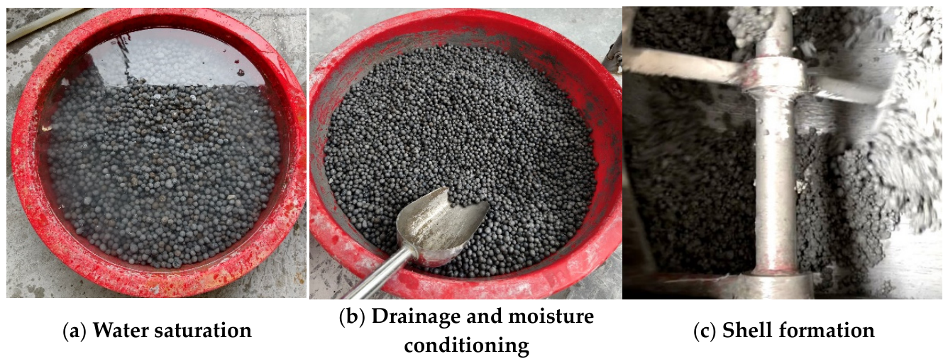
Figure 3.
Dry-wet cycle test.
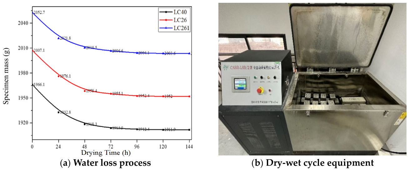
Figure 4.
Failure modes of fly ash ceramsite concrete under uniaxial compression load.
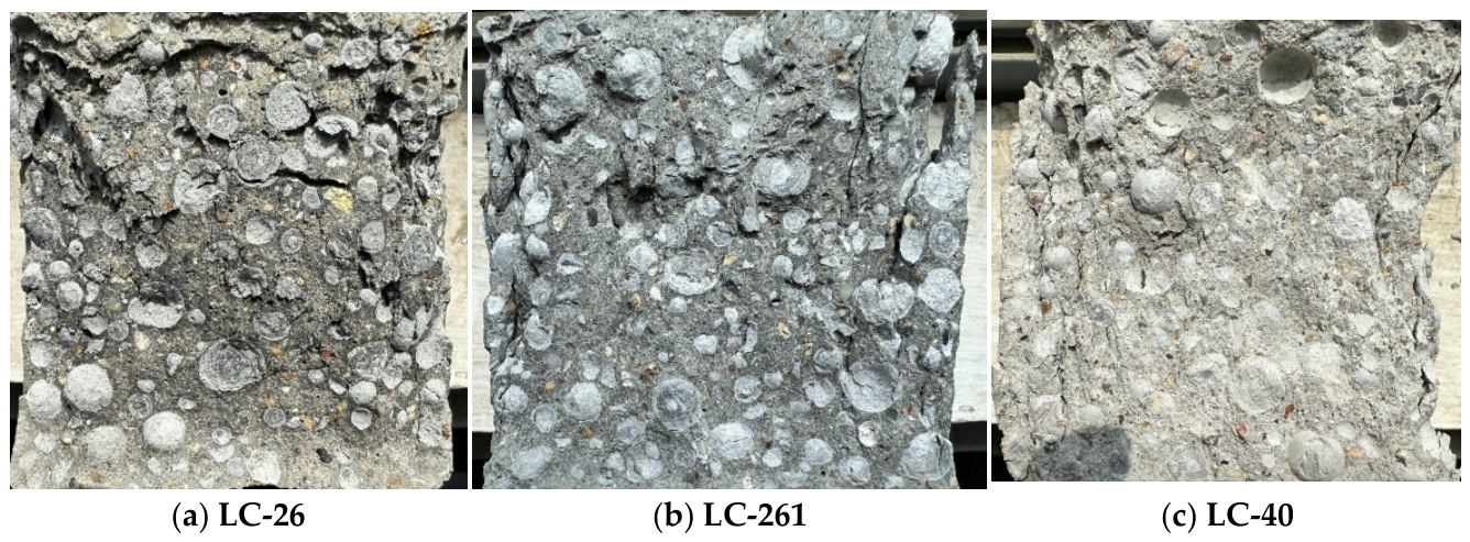
Figure 5.
Axial tensile test results of fly ash ceramsite concrete.
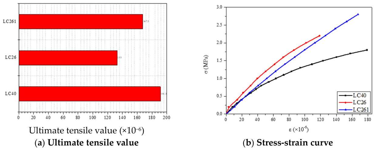
Figure 6.
Failure modes of fly ash ceramsite concrete under four-point flexural-tensile load.
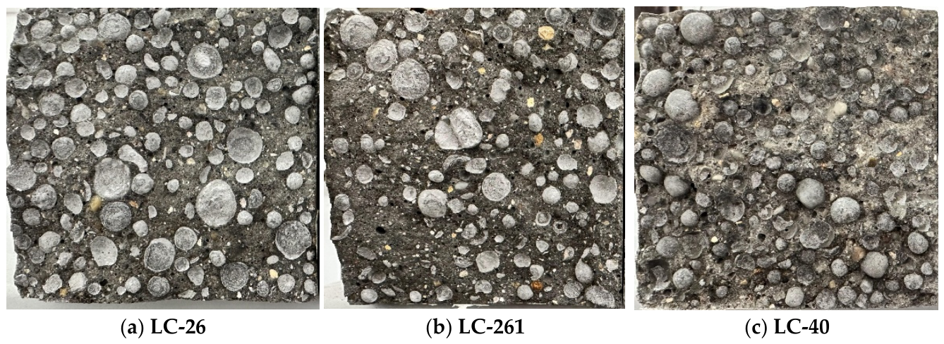
Figure 7.
Impermeability performance of fly ash ceramsite concrete.
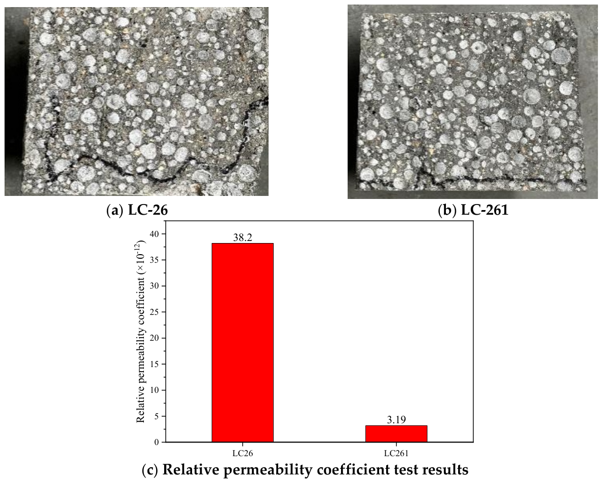
Figure 8.
Frost resistance specimens of fly ash ceramsite concrete.
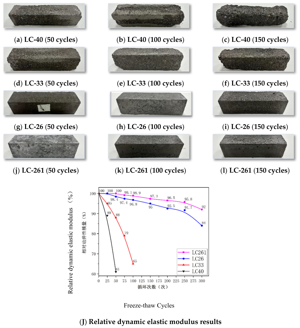
Figure 9.
Dry-wet cycle test results of concrete.
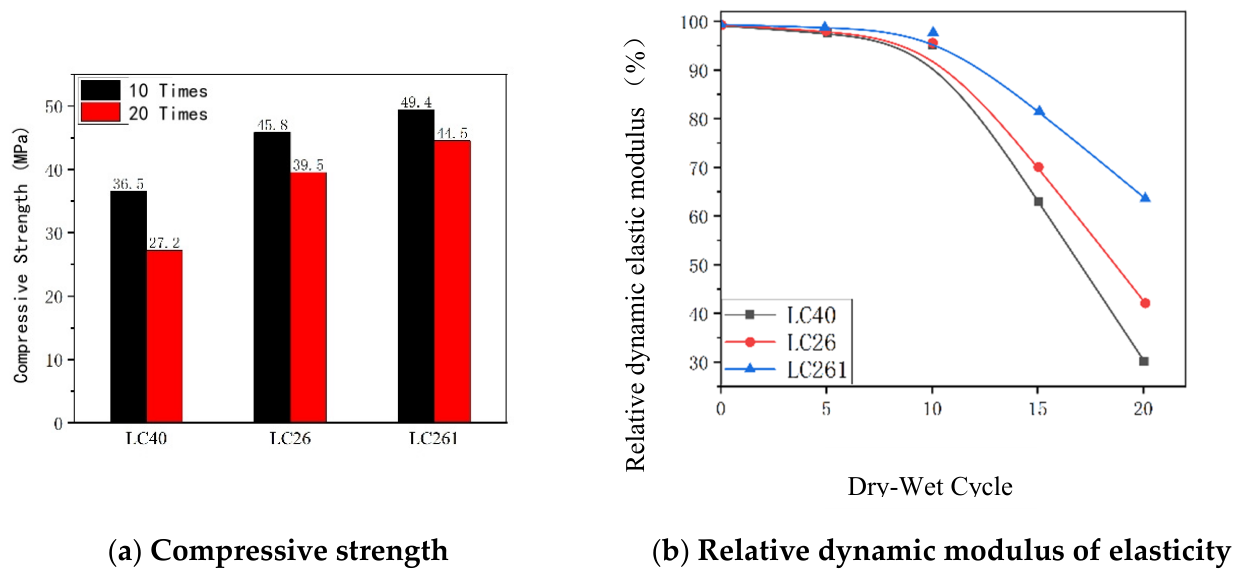
Figure 10.
Concrete cross-sections and bonding interfaces between Fly ash ceramsite and paste.
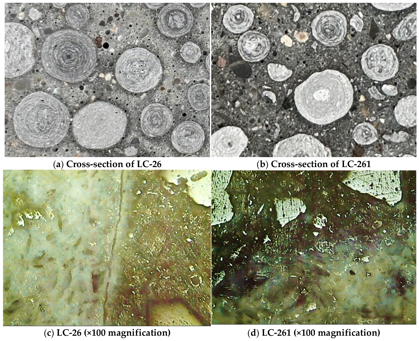
Figure 11.
Analysis results of concrete air void parameters.
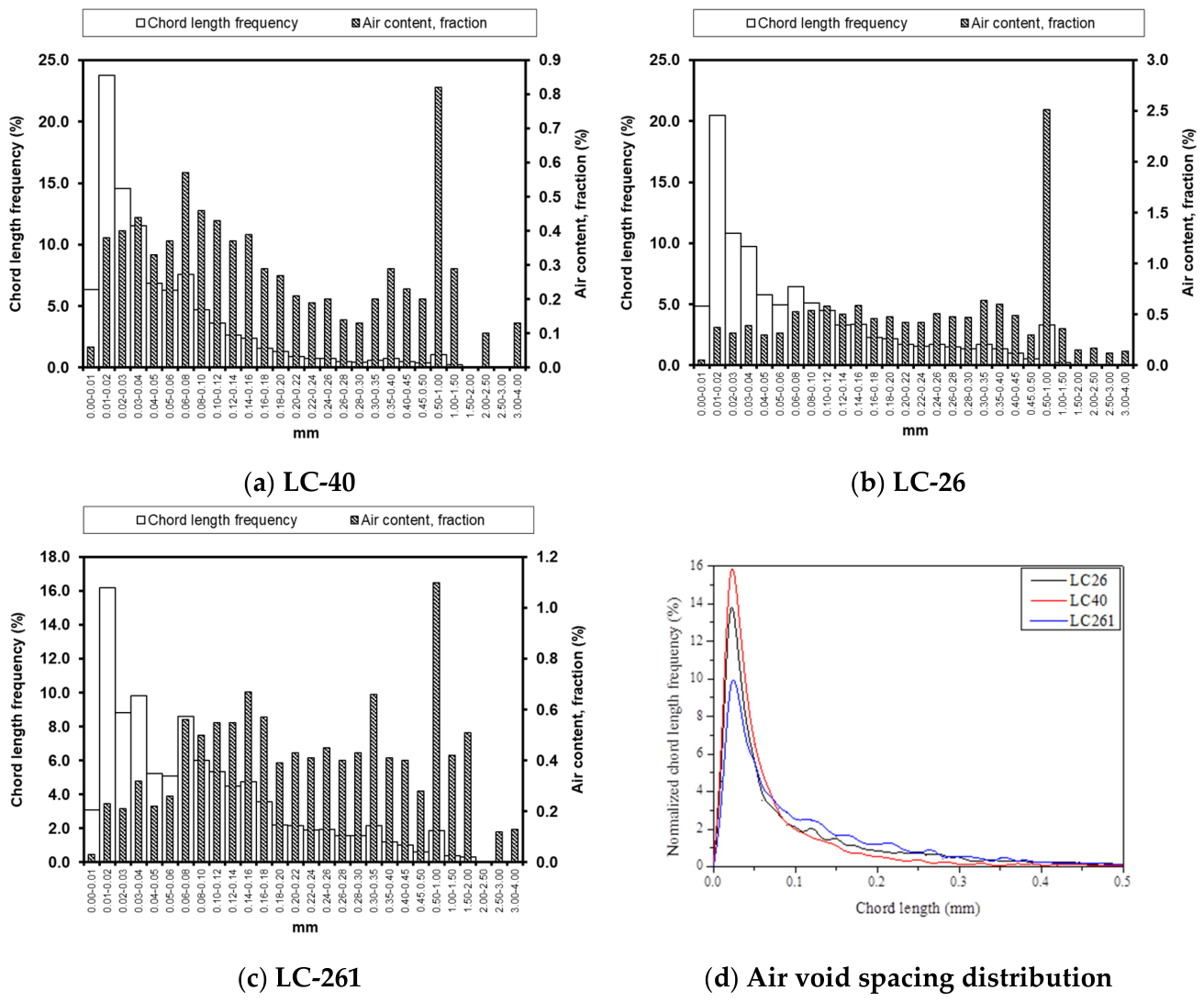
Figure 12.
Analysis of concrete microhardness test.
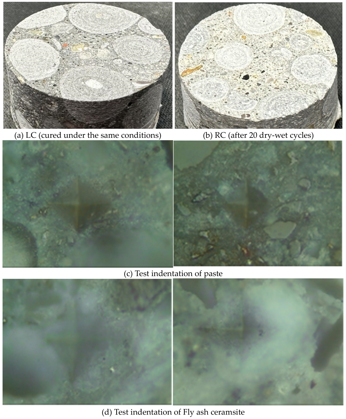

Table 1.
Basic properties of fly ash ceramsite.
| Performance Parameter | Test Method/Standard | Test Result |
|---|---|---|
| Bulk density (kg/m3) | GB/T 17431.1 | 1095 |
| Cylinder crushing strength (Mpa) | GB/T 17431.1 | 8.9 |
| Saturated surface dry apparent density (kg/m3) | SL/T 352 | 1800 |
| Water absorption (5~10 mm, %) | Freeze-drying method | 12.2 |
| Water absorption (10~20 mm, %) | Freeze-drying method | 12.1 |
Table 2.
Test mix proportions of fly ash ceramsite concrete.
| No. | Water-binder ratio | Coating | Dosage of each material (kg/m3) | |||||
| Cement | Silica fume | Water | Fine aggregate | fly ash ceramsite | Water reducer | |||
| LC-40 | 0.40 | None | 380 | 20 | 158 | 870 | 670 | 2.4 |
| LC-33 | 0.33 | None | 461 | 24 | 157 | 793 | 670 | 3.88 |
| LC-26 | 0.26 | None | 585 | 31 | 154 | 678 | 670 | 6.15 |
| LC-261 | 0.26 | Yes | 564 | 30 | 150 | 678 | 670 | 4.92 |
Table 3.
Mechanical properties of fly ash ceramsite concrete (28 days).
| Performance Index | LC-26 (Untreated) | LC-261 (Coated) | Performance Improvement |
| Cubic compressive strength (Mpa) | 32.1 | 38.9 | 21.2% |
| Axial compressive strength (Mpa) | 27.5 | 34.8 | 26.5% |
| Compressive modulus of elasticity (Gpa) | 15.0 | 17.5 | 16.7% |
| Flexural-tensile strength (Mpa) | 3.4 | 4.1 | 20.6% |
| Axial tensile strength (Mpa) | 2.5 | 2.9 | 16.0% |
| Ultimate tensile value (×10−6) | 145 | 162 | 11.7% |
Table 4.
Flexural-tensile test results of fly ash ceramsite concrete.
| No. | Age (d) | Flexural-tensile strength (MPa) | Compressive strength (Mpa) | Flexural-compressive strength ratio |
| LC40 | 28 | 2.6 | 22.1 | 1/8.5 |
| LC26 | 3.4 | 32.1 | 1/9.4 | |
| LC261 | 4.1 | 38.9 | 1/9.5 |
Table 5.
Test results of concrete air void parameters.
| No. | Air void spacing factor (μm) | Specific surface area of air voids (mm-1) | Average chord length (mm) | Air content (%) |
| LC-40 | 73.6 | 35.07 | 0.285 | 13.6 |
| LC-26 | 67.6 | 54.05 | 0.185 | 7.9 |
| LC-261 | 105.4 | 31.12 | 0.321 | 10.7 |
Table 6.
Changes in microzone microhardness (HV) of concrete before and after dry-wet cycles.
| Group | Test region | HV under same-condition curing | HV after 20 dry-wet cycles | Hardness loss rate |
| LC-26 | Cement paste | 83.4 | 84.1 | -0.8% |
| fly ash ceramsite | 49.6 | 30.2 | -39.10% | |
| LC-261 | Cement paste | 90.1 | 94.4 | -4.8% |
| fly ash ceramsite | 43.3 | 40.8 | -5.80% |
Disclaimer/Publisher’s Note: The statements, opinions and data contained in all publications are solely those of the individual author(s) and contributor(s) and not of MDPI and/or the editor(s). MDPI and/or the editor(s) disclaim responsibility for any injury to people or property resulting from any ideas, methods, instructions or products referred to in the content. |
© 2026 by the authors. Licensee MDPI, Basel, Switzerland. This article is an open access article distributed under the terms and conditions of the Creative Commons Attribution (CC BY) license (http://creativecommons.org/licenses/by/4.0/).
Copyright: This open access article is published under a Creative Commons CC BY 4.0 license, which permit the free download, distribution, and reuse, provided that the author and preprint are cited in any reuse.


