
Submitted:
21 July 2026
Posted:
23 July 2026
You are already at the latest version
Abstract
As converter-interfaced wind generation replaces synchronous units, power systems become more sensitive to active-power disturbances owing to reduced inertia and weakened governor response. To enhance frequency support, this paper proposes a Rate-of-Change-of-Frequency (RoCoF)-triggered hierarchical coordinated control strategy for wind power and battery energy storage systems (BESSs) in primary frequency regulation. The coordination layer converts frequency deviation and filtered RoCoF into an active-power support demand and determines the wind–BESS power split through SOC-corrected storage participation. The lower layer tracks the allocated commands under wind reserve, converter, deadband, SOC, and power-limit constraints. When RoCoF exceeds a preset threshold, the BESS share is increased for rapid active-power support; after RoCoF falls below the threshold, the allocation returns to baseline, and wind power provides sustained regulation. MATLAB/Simulink simulations under different wind penetrations, load disturbances, and wind speeds show improved frequency nadir, reduced RoCoF, shorter recovery time, and lower BESS energy use. At 25% wind penetration and a 0.10 pu load disturbance, the nadir increases from 49.62 to 49.77 Hz, and recovery time decreases from 5.0 to 2.1 s.
Keywords:
wind-storage joint frequency regulation
; primary frequency regulation
; hierarchical coordinated control
; virtual inertia-droop control
1. Introduction
The growing share of wind generation is changing the dynamic behavior of modern power systems. Unlike synchronous units, converter-interfaced wind turbines do not inherently release rotor kinetic energy in response to grid-frequency changes, because the converter control separates turbine mechanical dynamics from the electrical network. Therefore, a higher wind power share usually means that less rotating inertia and fewer governor-controlled reserves are available to arrest frequency deviations after disturbances [1,2,3]. Once a power imbalance occurs, the reduced inertial buffer makes the system less capable of slowing frequency decline, thereby increasing RoCoF, lowering the nadir, and delaying frequency restoration [4,5]. These changes increase the risk of frequency protection activation and place higher requirements on the response speed, support duration, and operational sustainability of frequency regulation resources [6,7,8].
Wind power can contribute to primary frequency regulation through converter-based active-power control. Current wind-side support strategies can be broadly divided into fast dynamic support and reserve-based regulation. The former is usually achieved through inertia emulation or rotor kinetic-energy release, whereas the latter relies on droop control, deloading operation, or pitch-angle regulation. Virtual inertia control generates additional active-power support according to RoCoF and can suppress rapid frequency variation during the initial stage of a disturbance [9,10,11,12]. Unlike virtual inertia, which mainly acts during rapid frequency variations, droop-based wind power control responds to the frequency error and contributes more to the recovery stage and steady-state frequency correction [10,13]. With this functional separation, wind turbines can assist the initial frequency arrest through inertia emulation and then continue supporting frequency restoration through droop response. However, the available frequency-support capability of a wind farm depends strongly on its operating point, available active-power reserve, converter capacity, and wind conditions [14,15,16]. When wind turbines provide too much short-term support by using stored rotor energy, part of the later output must be reserved for rotor-speed restoration. This recovery demand may weaken the post-disturbance power support and even trigger a secondary frequency decline [17,18,19]. Therefore, wind power alone generally cannot simultaneously guarantee rapid initial support, sustained regulation, and a smooth post-disturbance recovery process.
Because of their converter-based fast power control, BESSs are well suited to compensate for short-term power deficits during the early stage of frequency events. By rapidly injecting active power following a sudden load increase, a BESS can reduce the initial power deficit, suppress RoCoF, and improve the frequency nadir [20,21,22]. The fast response of a BESS does not mean that its regulation power can be supplied continuously; in practice, the available support is bounded by SOC margin, energy reserve, power rating, conversion efficiency, and converter operating constraints [23,24]. Repeated or prolonged high-power regulation may result in excessive SOC deviation, reduced available reserve, accelerated battery degradation, and increased operating costs [25,26]. Consequently, a BESS is more suitable for rapid short-duration support than for independently undertaking the entire primary frequency regulation task over an extended period.
The complementary dynamic characteristics of wind power and BESS provide a basis for coordinated wind–storage frequency regulation. In the proposed coordination logic, the BESS mainly undertakes the fast-response task immediately after a disturbance, whereas wind power carries more sustained regulation during the recovery stage. Existing studies have investigated coordinated wind–storage control using variable allocation coefficients, SOC feedback, wind-speed-dependent regulation, and system-frequency-support requirements [27,28,29,30,31]. Independent wind–BESS responses may cause overlap and mismatch. Existing allocation methods do not clearly separate fast support and recovery support, while device constraints are insufficiently coordinated. Hence, RoCoF-triggered hierarchical control with SOC-based allocation and constrained execution is required.
Figure 1 illustrates the frequency stability issues and coordinated control requirements under high wind power penetration. Converter-interfaced wind power reduces equivalent system inertia, leading to larger RoCoF, lower frequency nadir, and slower recovery. In independent control schemes, wind power and BESS may respond separately to the same frequency signal, causing response overlap and uncoordinated support. Therefore, a coordinated framework is required to distinguish the rapid frequency-variation stage from the recovery stage and allocate regulation tasks between wind power and BESS in a time-sequential manner.
The contributions of this paper are threefold:
1. An RoCoF-triggered wind–BESS hierarchical regulation scheme is designed to transform system-level frequency support demand into coordinated wind-side and storage-side power commands.
2. A time-sequential wind–storage power allocation mechanism is developed by combining SOC-based baseline allocation with RoCoF-triggered fast-support mode switching.
3. A constrained lower-layer execution mechanism is designed to ensure feasible tracking of the upper-layer allocation commands. Wind-side reserve and converter limits, together with BESS deadband, SOC zones, and power limits, are considered to improve the feasibility and sustainability of wind–storage frequency regulation.
The rest of the paper is arranged as follows: Section 2 establishes the wind–storage frequency response model; Section 3 introduces the RoCoF-triggered hierarchical control strategy; Section 4 presents the simulation cases and performance analysis; and Section 5 summarizes the main findings and future research directions.
2. System Model for Wind–Storage Joint Primary Frequency Regulation
This section builds a simplified wind–storage frequency response model that considers inertia reduction, wind-side support, and BESS regulation. Positive load disturbance denotes increased demand, whereas positive wind and BESS powers denote power injection into the grid.
2.1. System Configuration of Wind–Storage Joint Primary Frequency Regulation
As illustrated in Figure 2. The studied system integrates synchronous generation, wind power, BESS, aggregated load, an equivalent frequency response module, and a wind–storage coordination controller within a closed-loop frequency regulation framework. The conventional units provide inertia and governor-based primary frequency regulation, while the wind farm and BESS supply supplementary active-power support through converter-based control. The coordinated controller measures system frequency, RoCoF, and BESS SOC, and then allocates the required regulation power to the wind farm and BESS.
where is the measured system frequency and is the nominal system frequency.
The RoCoF signal is obtained by differentiating the frequency deviation:
The net active-power mismatch among conventional generation, wind power, BESS output, and load demand is defined as:
where is the active-power response of the conventional synchronous generating units, is the additional active-power output of the wind farm, is the BESS active-power output, and is the load disturbance. This expression represents the instantaneous power imbalance between generation and demand, which directly determines the frequency variation of the system. A positive indicates a surplus of generation, while a negative value indicates a power deficit that leads to frequency decline.
Based on the aggregated swing equation, the system frequency dynamics are expressed as:
where is the equivalent inertia coefficient of the system and is the equivalent load damping coefficient.
The equivalent inertia coefficient is related to the equivalent inertia constant by:
where is the equivalent inertia constant.
Taking the Laplace transform of Equation (4), the equivalent system frequency response transfer function is obtained as:
Equation (6) shows that larger system inertia reduces the initial RoCoF, while load damping helps suppress frequency deviation caused by active-power imbalance.
Figure Figure 2 illustrates the wind–storage primary frequency regulation system and its power, signal, and control paths.
As shown in Figure 2. The conventional units provide inertia and governor-based primary frequency regulation, while the wind farm and BESS supply supplementary active-power support. The measured , RoCoF, and BESS SOC are sent to the coordinated controller, which generates wind-side and BESS-side regulation commands. The actual outputs are then fed back to the system power balance, forming a closed-loop wind–storage frequency regulation process.
2.2. Equivalent Frequency Response Model of a Conventional Power System
In a conventional power system, multiple synchronous generating units can be equivalently represented by an aggregated unit including governor, turbine, inertia, and load damping characteristics.
The equivalent governor transfer function is expressed as:
where is the equivalent governor time constant.
The equivalent turbine transfer function is given by:
where is the equivalent turbine time constant.
Therefore, the combined governor–turbine transfer function is:
The mechanical power response of the conventional synchronous generating units is expressed as:
where is the equivalent governor droop coefficient. The negative sign indicates that a negative frequency deviation produces a positive mechanical power response.
When only the conventional synchronous generating units participate in primary frequency regulation, the system active-power balance in the frequency domain is:
Substituting Equation (10) into Equation (11) gives:
Therefore, the transfer function from the load disturbance to the system frequency deviation is:
Using the system frequency response transfer function , Equation (13) can also be written as:
For a step load disturbance, the steady-state frequency deviation can be obtained using the final value theorem:
Equation (15) indicates that the steady-state frequency deviation is mainly affected by load damping and governor droop, while system inertia primarily influences the initial RoCoF and transient response.
Figure 3 illustrates the equivalent frequency response model of a conventional power system, which includes the governor droop, turbine dynamics, system frequency response, load disturbance, and power feedback loops.
As shown in Figure 3. The frequency deviation is fed back through the governor droop link to regulate the mechanical power output. The load disturbance and electrical power deviation jointly determine the active-power imbalance, which is then processed by the system frequency response model to obtain . This model represents the basic frequency regulation process of a conventional synchronous-generator-dominated power system.
2.3. Equivalent Frequency Response Model with Wind Power Integration
When wind power replaces part of conventional synchronous generation, the system equivalent inertia decreases. The equivalent inertia constant can be expressed as:
where and are the inertia constant and rated capacity of the -th synchronous generating unit, respectively, and is the system base capacity.
Assuming that a proportion of synchronous generation is replaced by converter-interfaced wind power and that the wind farm does not provide synthetic inertia, the equivalent inertia can be approximately expressed as:
where is the equivalent inertia constant of the original synchronous-generation-dominated system.
The corresponding equivalent inertia coefficient is:
After wind power integration, the conventional system frequency response becomes:
Equation (19) indicates that higher wind power penetration reduces system inertia and increases the initial RoCoF under the same load disturbance.
Immediately after a load disturbance, the governor and turbine responses are still limited. Without fast support from wind power or BESS, the initial RoCoF can be approximated as:
Equation (20) shows that lower equivalent inertia leads to a larger initial RoCoF, highlighting the need for fast active-power support from wind power and BESS.
Figure 4 shows the equivalent frequency response model with wind power and energy storage integration. Compared with Figure 3, the frequency regulation response consists of conventional generation, wind power, and BESS support, where denotes the wind power penetration and denotes the remaining synchronous generation proportion.
As shown in Figure 4. Conventional generation, wind power, and BESS jointly contribute to the system active-power balance through , , and , respectively. The combined response is fed into the frequency dynamic model, where the load disturbance acts as a negative input. This model indicates that wind power penetration reduces synchronous inertia, while coordinated wind–storage support improves the dynamic frequency response.
2.4. Primary Frequency Regulation Model of the Wind Farm
Variable-speed wind turbines are connected through power-electronic converters, which decouple rotor dynamics from grid frequency under MPPT operation. Therefore, they do not naturally provide inertial response like synchronous generators.
By introducing supplementary active-power control, the wind farm can provide virtual inertia and droop-based frequency support. The wind-side virtual inertia component is expressed as:
where is the wind-side virtual inertia coefficient and is the filtering time constant applied to the RoCoF signal.
The wind-side droop response is expressed as:
where is the wind-side droop coefficient and is the equivalent response time constant of the wind power control system.
The total unconstrained wind-side frequency regulation response is:
Substituting Equations (21) and (22) into Equation (23) gives:
The equivalent frequency response function of the wind farm is defined as:
Therefore:
Considering the converter and active-power controller dynamics, the wind-farm power tracking model is represented as:
where is the equivalent wind-farm active-power response time constant and is the power command allocated to the wind farm.
The actual wind-side frequency regulation power is constrained by the available upward and downward active-power regulation capacities:
The saturation function is defined as:
The available upward regulation capacity of the wind farm can be expressed as:
where is the available wind power under the current operating condition and is the pre-disturbance operating power of the wind farm.
Virtual inertia supports the initial disturbance stage, whereas droop control sustains frequency recovery. The actual wind-side support is limited by reserve, rotor-speed constraints, operating point, and converter capacity.
Figure 5 shows the wind farm primary frequency regulation model, including virtual inertia, droop control, active-power response dynamics, and power-limiting correction. It describes how the wind farm converts frequency deviations into additional active-power support.
As shown in Figure 5. The wind-side controller uses the frequency deviation to generate additional active-power support through virtual inertia and droop control. The virtual inertia coefficient responds to RoCoF, while the droop coefficient responds to frequency deviation. After response-delay filtering and power-limiting correction, the wind-side regulation power is obtained.
2.5. Primary Frequency Regulation Model of the Battery Energy Storage System
The BESS is connected to the grid through a bidirectional converter and can rapidly regulate active power, making it suitable for compensating for the initial power deficit after a disturbance. In the proposed hierarchical structure, the BESS tracks the power command allocated by the upper-layer controller, and its active-power dynamics are expressed as:
where is the equivalent response time constant of the BESS and its grid-connected converter, and is the BESS power reference.
The BESS active-power output must satisfy the charging and discharging power limits:
where and are the maximum charging and discharging powers, respectively. Under the adopted sign convention, positive represents discharging power injected into the grid, whereas negative represents charging power absorbed from the grid.
The BESS state of charge is defined as:
where is the stored energy, and is the rated energy capacity of the BESS.
Since is expressed in MW and in MWh, the factor 3600 is introduced to convert seconds to hours. With positive as discharging power injected into the grid, the continuous-time SOC dynamics are expressed as:
where and are the discharging and charging efficiencies, respectively. The factor 3600 converts seconds to hours.
For a digital control system with a sampling interval , the SOC can be updated using:
The SOC must remain within the safe operating interval:
To maintain sufficient charging and discharging capability, the BESS operates around . Discharging power is reduced near the lower SOC limit, while charging power is restricted near the upper SOC limit.
The feasible BESS power can therefore be written as:
where and are the available charging and discharging powers considering both the rated-power and SOC constraints.
The BESS can rapidly track the allocated regulation command, but its output is constrained by converter capacity, rated energy, charge–discharge efficiency, and SOC limits. These constraints are incorporated into the lower-layer command correction mechanism.
2.6. Equivalent Frequency Response Model of Wind–Storage Joint Primary Frequency Regulation
When conventional synchronous generating units, the wind farm, and the BESS jointly participate in primary frequency regulation, the system active-power balance in the frequency domain can be expressed as:
Substituting the active-power response of the conventional generating units into Equation (38) gives:
For system-level analysis, the combined frequency-support response of the wind farm and BESS is defined as:
where is the equivalent closed-loop frequency-support function of the wind–storage system.
Therefore, the transfer function from the load disturbance to the system frequency deviation is:
Equation (41) indicates that the system frequency response depends on equivalent inertia, load damping, governor regulation, and wind–storage active-power support. The BESS mainly provides rapid compensation during the initial disturbance stage, while wind power offers sustained support during frequency recovery, providing the basis for the proposed hierarchical coordinated control strategy.
3. Hierarchical Coordinated Control Strategy for Wind–Storage Joint Primary Frequency Regulation
This section proposes a RoCoF-triggered hierarchical coordinated control strategy for wind–storage primary frequency regulation. The upper layer generates a unified regulation command from frequency deviation and RoCoF and allocates wind–storage power based on BESS SOC and RoCoF-triggered mode switching. The lower layer executes commands under wind power reserve, frequency deadband, SOC, and charge–discharge limits, enabling fast BESS support during the initial disturbance stage and sustained wind power regulation during recovery.
3.1. Overall Structure of the Hierarchical Coordinated Control System
Figure Figure 6 shows the overall structure of the proposed hierarchical coordinated control strategy. The grid frequency is measured to obtain the frequency deviation, and the RoCoF signal is filtered by a first-order filter to reduce measurement noise:
where is the filtered RoCoF signal and is the RoCoF filtering time constant.
The upper-layer controller uses , filtered RoCoF , and BESS SOC to generate the total regulation command and allocate it between the wind farm and BESS. The lower-layer controllers execute the allocated commands under wind power reserve, converter limits, frequency deadband, SOC correction, dynamic tracking, and charge–discharge power limits. The actual wind and BESS outputs are fed back to the system power balance and upper-layer controller, forming a closed-loop coordinated frequency regulation process.
During a sudden load increase, a large RoCoF activates the rapid BESS support mode and increases the BESS power share. As RoCoF decreases below the threshold, the controller returns to the SOC-based baseline mode, shifting more sustained regulation to wind power and reducing BESS energy consumption.
3.2. Upper-Layer Wind–Storage Power Allocation Control
The upper-layer controller generates the total wind–storage frequency regulation power command and allocates it between the wind farm and the BESS according to the BESS SOC and the RoCoF-triggering state.
The total frequency regulation power command is expressed as:
where is the total wind–storage regulation command, and are the frequency-deviation and RoCoF regulation coefficients, respectively. For a sudden load increase, both and are negative; thus, , indicating active-power injection into the grid.
Under normal operating conditions, the baseline BESS allocation coefficient is adjusted according to its SOC:
where is the initial BESS allocation coefficient, is the SOC correction coefficient, is the reference SOC, and and are the lower and upper limits of the BESS allocation coefficient, respectively.
When is above , the BESS can undertake a larger regulation share; when is below , its share is reduced to avoid prolonged discharge and improve regulation sustainability.
To identify the rapid frequency-variation stage immediately following a disturbance, the RoCoF-triggering state is defined as:
where is the RoCoF-triggering state and is the preset RoCoF threshold.
The final BESS allocation coefficient is determined by:
When , the rapid BESS support mode is activated, and the BESS allocation coefficient switches to its preset upper limit. When , the allocation coefficient returns to the SOC-based baseline value.
The BESS and wind-side frequency regulation power commands are respectively given by:
The allocated commands satisfy:
Thus, the BESS provides more rapid support during the initial disturbance stage, while wind power provides more sustained regulation during recovery. RoCoF is used only as a mode-switching trigger, rather than a continuously varying allocation variable.
3.3. Lower-Layer Power Command Execution and Constraint Correction
The lower-layer controllers track the wind-side and BESS-side commands allocated by the upper layer, without generating new system-level regulation commands. They only correct and execute the commands according to the operating limits of the wind farm and BESS.
The wind farm receives the command , and its active-power reference is expressed as:
where is the pre-disturbance operating power of the wind farm.
Considering the wind-farm active-power response dynamics and available regulation limits, the actual wind-side frequency regulation power is:
where is the equivalent wind-farm active-power response time constant, and and are the available downward and upward regulation limits, respectively.
The wind-side virtual inertia and droop control determine the wind farm response within the allocated command and power limits. Virtual inertia mainly supports the initial dynamic stage, while droop control provides sustained support during frequency recovery.
The BESS receives the command . A frequency deadband is introduced to avoid unnecessary charge–discharge actions, while the deadband is bypassed during the RoCoF-triggered rapid-support mode:
where is the frequency deadband threshold.
The BESS command is then corrected according to its SOC operating state:
where is the SOC-dependent correction coefficient and satisfies:
When the SOC remains within the normal operating range, =1, and the BESS fully executes the allocated command. When the SOC approaches its upper or lower operating limit, is reduced to restrict further charging or discharging.
Considering the BESS response dynamics and charging/discharging power limits, the actual BESS output is expressed as:
where is the equivalent response time constant of the BESS, while and are the maximum charging and discharging powers, respectively.
With deadband, SOC correction, dynamic tracking, and power limiting, the BESS rapidly executes the upper-layer command while avoiding unnecessary cycling, excessive SOC deviation, and converter overloading.
After lower-layer command execution and constraint correction, the actual combined wind–storage frequency regulation power is:
The combined wind–storage response acts on the system power balance, while the resulting frequency and BESS SOC are fed back to the upper layer, forming a closed-loop process of command generation, power allocation, constrained execution, and state feedback.
In summary, the upper layer generates and allocates the unified regulation command according to SOC and RoCoF-triggering results, while the lower layer executes the commands within wind power and BESS operating limits. This structure enables rapid BESS support during the initial disturbance stage and sustained wind power regulation during frequency recovery.
4. Results and Discussion
4.1. Simulation Setup
To verify the proposed strategy, a wind–storage primary frequency regulation model is developed in MATLAB/Simulink, including conventional units, a wind farm, a BESS, an aggregated load, an equivalent frequency response model, and the proposed controller. The main parameters are listed in Table 1.
Four strategies are compared under identical conditions. Wind-speed tests evaluate adaptability, where wind speed affects only the wind operating point and available reserve, not the controller input. The main metrics include frequency nadir, maximum RoCoF, recovery time, steady-state frequency deviation, BESS power, and SOC trajectory.
4.2. Frequency Responses Under Different Control Strategies
Figure 8 presents the step load disturbances and the corresponding equivalent net-load power responses. Step disturbances of 0.05, 0.075, 0.10, and 0.125 pu are applied at t = 4 s. Immediately after each disturbance, the active-power demand increases rapidly, creating a generation–load imbalance. As the disturbance magnitude increases, both the peak value and variation amplitude of the equivalent net-load power increase, indicating a greater requirement for rapid frequency support.
In addition to the rapid active-power support provided by the BESS, the conventional synchronous generating units continue to contribute physical inertia and governor-based primary frequency regulation. To further analyze the dynamic response of the conventional generating units under different disturbance magnitudes, based on the BESS power and SOC responses, Figure 10 further compares the overall frequency responses of different control strategies under wind power penetration levels of 10%, 25%, and 40%.


Without wind-side frequency support, the post-disturbance power imbalance is mainly compensated by conventional synchronous units, so the frequency drops more deeply and recovers more slowly, particularly at higher wind penetration levels. Droop-based wind control improves the final frequency offset by adjusting active power according to frequency deviation; however, its effect on the initial RoCoF and frequency nadir remains limited because it does not explicitly identify the fast frequency-change stage. By contrast, the proposed hierarchical coordinated control forms a common regulation command and distributes it according to BESS SOC and RoCoF-triggering state. In this way, the BESS provides rapid support at the beginning of the disturbance, while wind power contributes longer-duration regulation during recovery. The proposed strategy therefore achieves a higher frequency nadir, a lower maximum RoCoF, a shorter recovery time, and a smaller steady-state frequency deviation. Under a wind power penetration level of 25% and a load disturbance of 0.10 pu, the frequency nadir is increased from 49.62 Hz to 49.77 Hz, while the recovery time is reduced from 5.0 s to 2.1 s. The steady-state frequency deviation is also reduced from 0.087 Hz to 0.058 Hz. These results demonstrate that the improvement is not simply caused by the addition of the BESS, but by the coordinated allocation and constrained execution mechanisms of the proposed strategy.
When the system operates with a higher wind share or is subjected to a larger load step, the frequency response becomes more severe for all control strategies. Nevertheless, the proposed strategy consistently provides the best frequency response, indicating that it can maintain effective wind–storage coordination under different system operating conditions.
4.3. Frequency Regulation Performance Under Different Wind Speeds
Wind speed affects the wind turbine operating point, available aerodynamic power, and active-power regulation reserve. To evaluate the adaptability of the proposed strategy, simulations are conducted at wind speeds of 3, 6, 9, and 12 m/s under a wind power penetration level of 25% and a load disturbance of 0.10 pu.
Figure 11 compares the frequency responses of the uncoordinated wind–storage control and the proposed hierarchical coordinated control under different wind speed conditions.
The observed differences among the frequency response curves are mainly caused by changes in the turbine operating point and available wind-side active-power reserve under different wind speeds. The relationship between wind speed and frequency regulation capability is not strictly monotonic. At some operating points, an increase in wind speed raises the normal wind power output but reduces the available upward regulation margin.
Despite these variations, the proposed hierarchical coordinated control consistently improves the frequency nadir and reduces the maximum RoCoF under all tested wind speeds. A quantitative comparison of the frequency regulation performance at different wind speeds is provided in Table 2.
At wind speeds of 3, 6, 9, and 12 m/s, the proposed strategy increases the nadir frequency by 0.028, 0.033, 0.036, and 0.050 Hz, respectively. The corresponding maximum RoCoF values are reduced from 0.397, 0.594, 0.724, and 1.386 Hz/s to 0.330, 0.525, 0.654, and 1.312 Hz/s.
The proposed strategy slightly delays the frequency nadir, showing that rapid BESS support slows the initial frequency decline. When wind reserve is limited, the RoCoF trigger increases the BESS share; otherwise, wind power provides sustained regulation. Thus, the strategy adapts to different wind operating points without using wind speed as an upper-layer input.
5. Conclusions and Future Work
This paper develops a RoCoF-triggered hierarchical coordination method for wind–storage primary frequency regulation. In the coordination layer, frequency deviation and filtered RoCoF are used to determine the total active-power support demand, while the BESS participation share is corrected according to SOC. When the RoCoF threshold is exceeded, the storage unit is assigned a larger share to arrest the initial frequency decline; after the system enters the recovery stage, the allocation returns to the SOC-based baseline mode, allowing wind power to undertake longer-duration regulation. In the execution layer, wind-side reserve limits, converter constraints, storage deadband, SOC correction, and charge/discharge power limits are considered to ensure feasible command tracking. Simulation results under different wind penetrations, load disturbances, and wind speeds verify that the proposed method raises the frequency nadir, suppresses RoCoF, accelerates frequency recovery, and reduces unnecessary BESS energy use. For the case of 25% wind penetration and a 0.10 pu load disturbance, the frequency nadir is improved from 49.62 Hz to 49.77 Hz, and the recovery time is shortened from 5.0 s to 2.1 s. Future research will focus on adaptive parameter tuning, hysteresis-based RoCoF triggering, coordinated SOC restoration, and hardware-in-the-loop validation.
Acknowledgments
This work was supported by the Major Science and Technology Special Project of Xinjiang Uygur Autonomous Region (Grant No. 2023A01005-1). The authors gratefully acknowledge this support.
References
- Idoko, Idoko Peter; et al. Empowering sustainable power generation: The vital role of power electronics in California's renewable energy transformation. World J. Adv. Eng. Technol. Sci. 2024, 11.1, 274–293. [Google Scholar] [CrossRef]
- Cui, Xiaobo; et al. The primary frequency modulation control strategy based on fuzzy active disturbance rejection control for gas turbines. Meas. Control 2025, 58.1, 15–23. [Google Scholar]
- Meng, Qinglin; et al. Enhancing distribution system stability and efficiency through multi-power supply startup optimization for new energy integration. IET Gener. Transm. Distrib. 2024, 18.21, 3487–3500. [Google Scholar] [CrossRef]
- Ye, Lin; et al. "Frequency characteristics analysis of power system under determined new energy penetration rate considering different start-up methods and frequency modulation participation degree. Syst. Sci. Control Eng. 2025, 13.1, 2486115. [Google Scholar]
- Liu, Wenju; et al. A coordinative optimization for hybrid energy storage system based on scenario and allocation of wind power generation. J. Energy Storage 2026, 141, 119162. [Google Scholar] [CrossRef]
- Leon, Andres E.; del Nozal, Álvaro Rodríguez; Mauricio, Juan Manuel. Frequency support strategy for fast response energy storage systems. IEEE Trans. Power Syst. 2024, 39.3, 5439–5442. [Google Scholar] [CrossRef]
- Huai, Rixu; Wei, Bo; Ding, Huilai. Mitigating Secondary Frequency Drop for Wind Farm: An ADRC-Based Auxiliary Strategy of Energy Storage Systems. J. Control Autom. Electr. Syst. 2026, 1–15. [Google Scholar] [CrossRef]
- Ullah, F.; Zhang, X.; Khan, M.; et al. A comprehensive review of wind power integration and energy storage technologies for modern grid frequency regulation[J]. Heliyon 2024, 10(9). [Google Scholar] [CrossRef] [PubMed]
- Hamanah, Waleed M.; et al. Realization of robust frequency stability in low-inertia islanded microgrids with optimized virtual inertia control. IEEE Access 2024, 12, 58208–58221. [Google Scholar] [CrossRef]
- Song, Y.; Zhang, Y.; Zhang, S.; et al. System frequency response model and droop coefficient setting considering renewable energy participation in frequency regulation[J]. Front. Energy Res. 2024, 12, 1521209. [Google Scholar]
- Li, Yang; et al. Optimal short-term frequency support strategy for multiple wind turbines based on synchronous release of rotor kinetic energy. IEEE Transactions on Industrial Electronics, 2025. [Google Scholar]
- Bonfiglio, Andrea; et al. Design, realization and testing of a synthetic inertia controller for wind turbine power generators. Sustain. Energy Grids Netw. 2024, 38, 101234. [Google Scholar]
- Yao, Junyi; et al. Inertia and damping characteristics analysis of grid-tied ESS based on power-frequency sag control. IET Conference Proceedings CP880, 2024; The Institution of Engineering and Technology: Stevenage, UK; Vol. 2024. [Google Scholar]
- Adebayo; Victor, Adeyinka; Adebayo, Hussein Kehinde; Oladeji, Samuel. Implementing Electrical Energy Storage for Improved Voltage Stability in Power Systems with Substantial Wind Generation. [PubMed]
- Rahman, Shahinur. Grid Integration of Wind Turbines and Wind Power Plants-Dynamic PQ Capability and Conventional/Intelligent Control; The University of Alabama, 2024. [Google Scholar]
- AnPing, Wan; et al. Advancing wind turbine performance and reliability through a real-time proposed robust control framework. World J. Eng. 2026, 23.4, 934–945. [Google Scholar]
- Cheng, Yi; et al. A consecutive power dispatch in wind farms to mitigate secondary frequency dips. Int. J. Electr. Power Energy Syst. 2024, 158, 109939. [Google Scholar] [CrossRef]
- Banjanin, Mladen; Milovanović, Miloš; Radosavljević, Jordan. Voltage dips and swells detection by sliding fast Fourier transform: Possibilities for application in modern distribution networks. J. Electr. Eng. 2025, 76.1, 58–71. [Google Scholar] [CrossRef]
- Jin, Yonglin; et al. Modeling and Response Characterization of Wind Turbines under Frequency-Voltage Coupled Disturbance Conditions. In 2024 IEEE 8th Conference on Energy Internet and Energy System Integration (EI2); IEEE, 2024. [Google Scholar]
- Elalfy, D. A.; Gouda, E.; Kotb, M. F.; et al. Comprehensive review of energy storage systems technologies, objectives, challenges, and future trends[J]. Energy Strategy Rev. 2024, 54, 101482. [Google Scholar] [CrossRef]
- Wang, Rutian; et al. "Coordinated control strategy for microgrid containing VSG and synchronous generator: Coordinated control strategy. J. Power Electron. 2026, 26.2, 395–405. [Google Scholar]
- Aghmadi, Ahmed; Mohammed, Osama A. Energy storage systems: technologies and high-power applications. Batteries 2024, 10.4, 141. [Google Scholar]
- Kang, H.; Sun, Y.; Liu, J.; et al. Research on the Primary Frequency-Regulation Strategy of Wind-Storage Collaborative Participation Systems Considering the State of Charge of Energy Storage[J]. Energies 2024, 17(24), 6333. [Google Scholar] [CrossRef]
- Cai, Tingting; Sun, Yugang. A wind–storage coordinated frequency regulation and power optimization control strategy based on multivariable fuzzy logic and model predictive control. Energies 2026, 19.9, 2071. [Google Scholar]
- Xue, Shiwei; et al. Adaptive secondary frequency regulation strategy for energy storage based on dynamic primary frequency regulation. IEEE Trans. Power Deliv. 2024, 39.6, 3503–3513. [Google Scholar] [CrossRef]
- Islam, Muhammad Muzammal; et al. Improving reliability and stability of the power systems: A comprehensive review on the role of energy storage systems to enhance flexibility. IEEE Access 2024, 12, 152738–152765. [Google Scholar] [CrossRef]
- Njoka; Macharia, Godfrey; Mogaka, Lucas; Wangai, Agnes. Impact of variable renewable energy sources on the power system frequency stability and system inertia. Energy Rep. 2024, 12, 4983–4997. [Google Scholar] [CrossRef]
- Shu, Hongchun; et al. Coordinated control of wind-storage combined with primary frequency regulation and variable coefficient based on wind speed and SOC. J. Energy Storage 2024, 87, 111356. [Google Scholar] [CrossRef]
- Jiang, Yu; et al. Wind/storage coordinated control strategy based on system frequency regulation demands. Energy Rep. 2024, 11, 1551–1559. [Google Scholar] [CrossRef]
- Adeyinka; Miracle, Adekanmi; et al. Advancements in hybrid energy storage systems for enhancing renewable energy-to-grid integration. Sustain. Energy Res. 2024, 11.1, 26. [Google Scholar]
- Fawzy, Samaa; et al. Optimal location and operation of energy storage and transmission switching for minimizing wind power spillage. J. Energy Storage 2024, 90, 111925. [Google Scholar] [CrossRef]
Figure 1.
Key frequency stability issues and coordinated control requirements of wind–battery energy storage systems under high wind power penetration.
Figure 1.
Key frequency stability issues and coordinated control requirements of wind–battery energy storage systems under high wind power penetration.
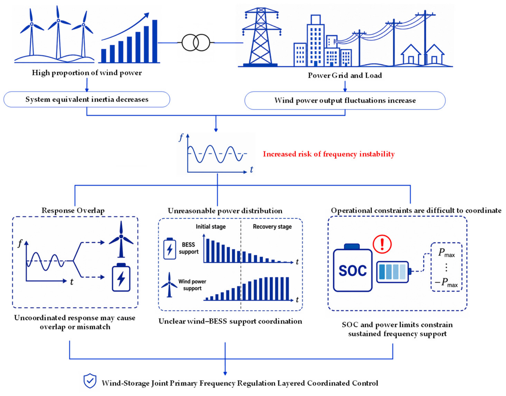
Figure 2.
System configuration of wind–storage joint primary frequency regulation.
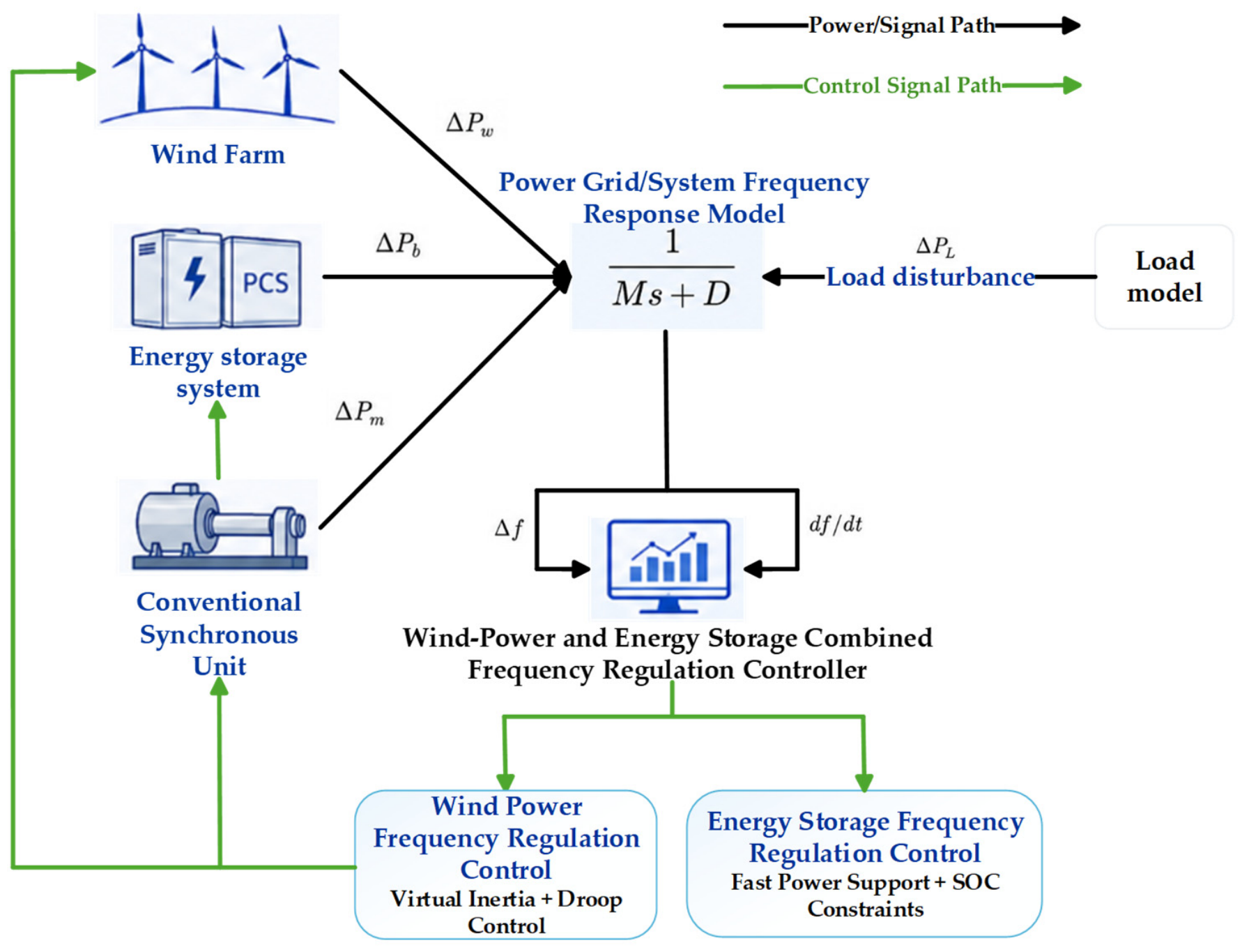
Figure 3.
Equivalent frequency response model of a conventional power system.
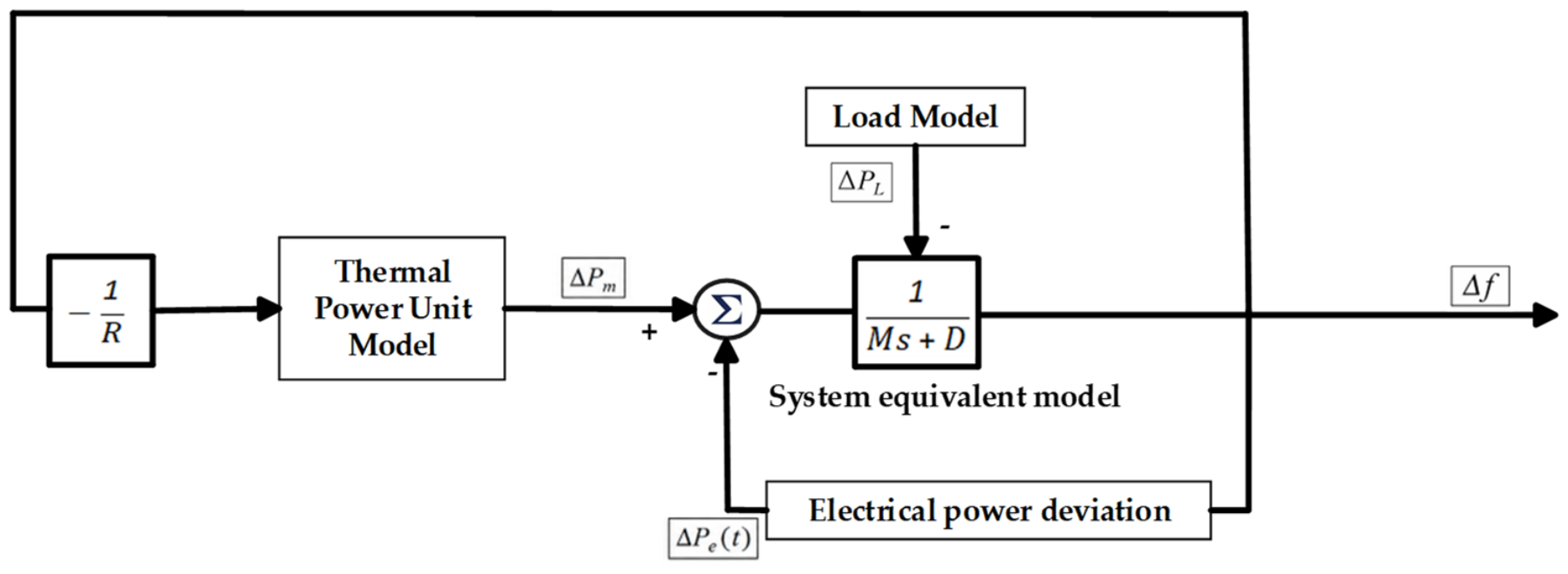
Figure 4.
Equivalent frequency response model with wind power integration.
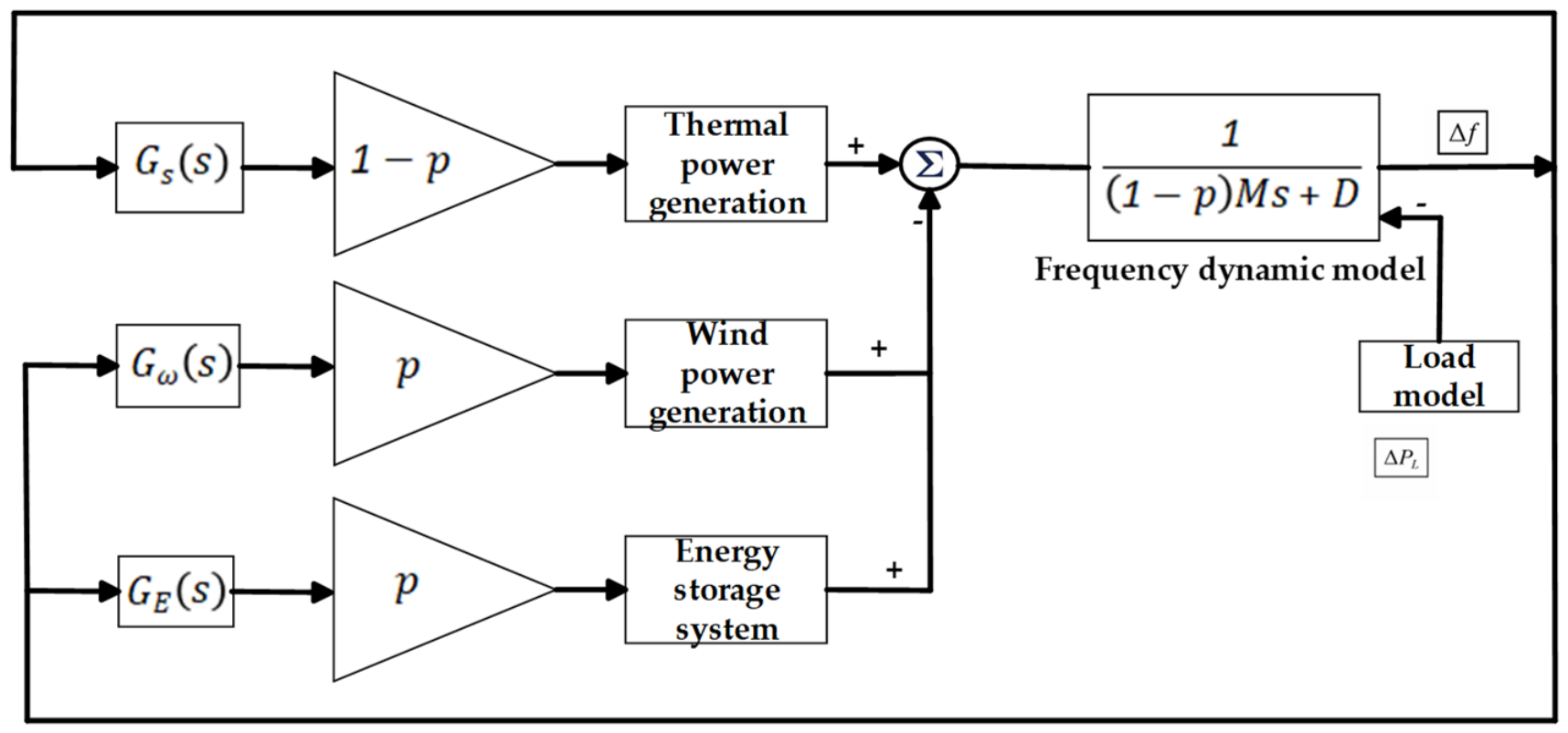
Figure 5.
Equivalent primary frequency regulation model of the wind farm.
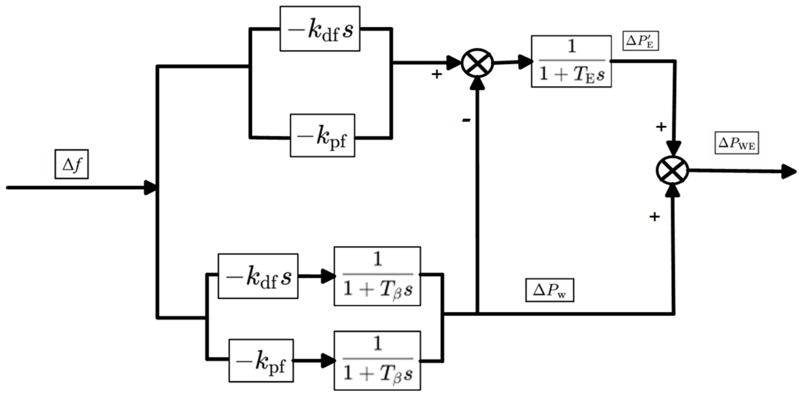
Figure 6.
Hierarchical coordinated control structure for wind–storage joint primary frequency regulation.
Figure 6.
Hierarchical coordinated control structure for wind–storage joint primary frequency regulation.
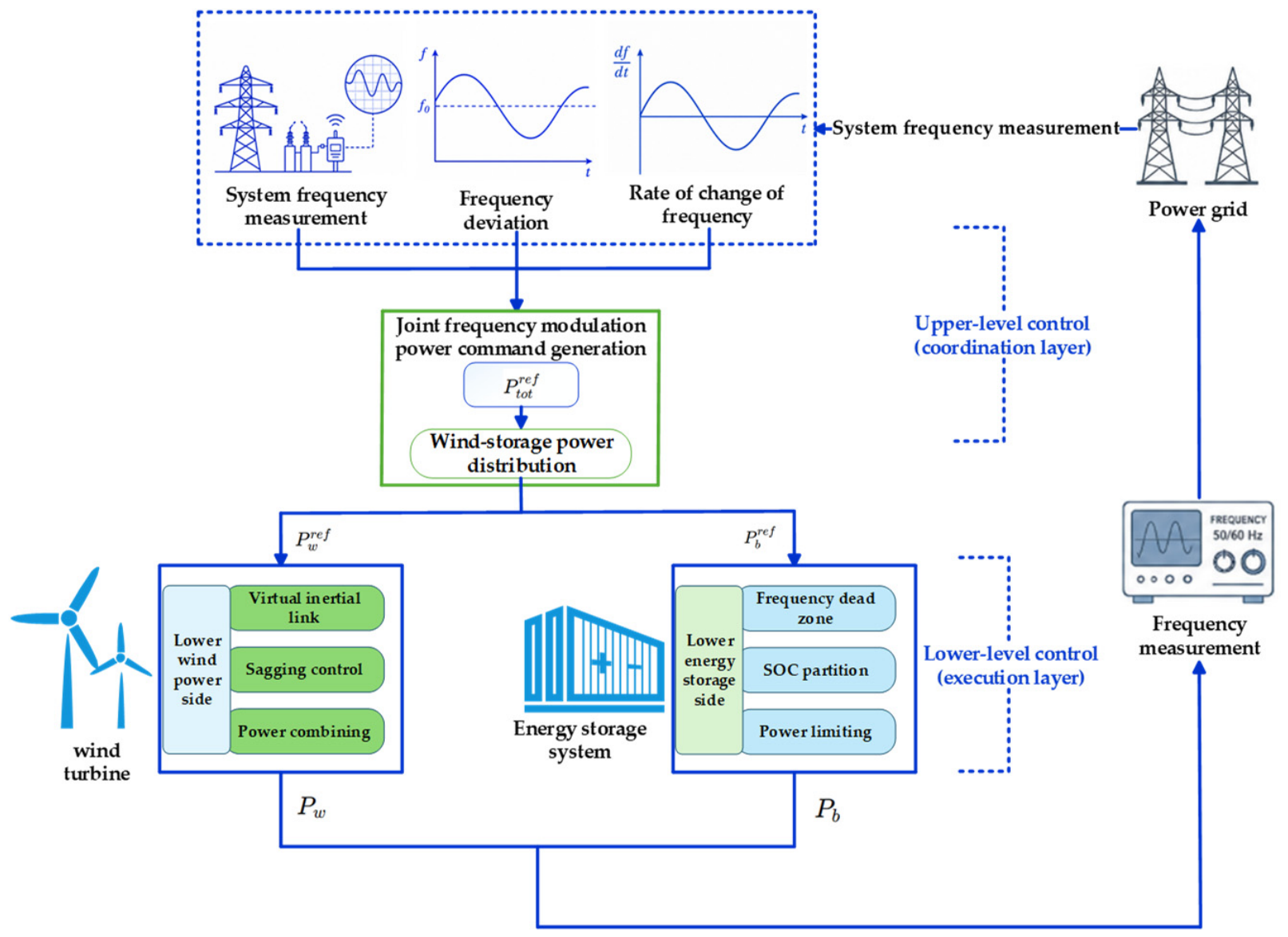
Figure 7.
Flowchart of the RoCoF-triggered hierarchical coordinated control strategy.
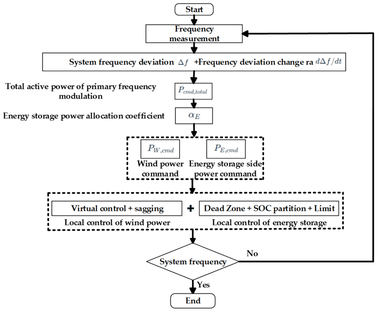
Figure 8.
Load step inputs and equivalent net-load power responses under different disturbance magnitudes.
Figure 8.
Load step inputs and equivalent net-load power responses under different disturbance magnitudes.
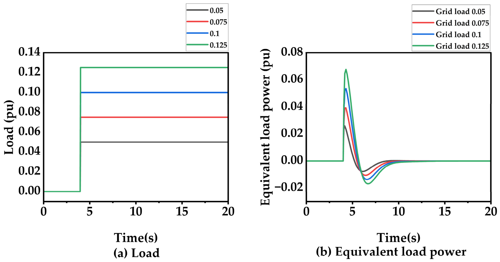
Figure 9.
BESS frequency regulation power response and SOC trajectory.
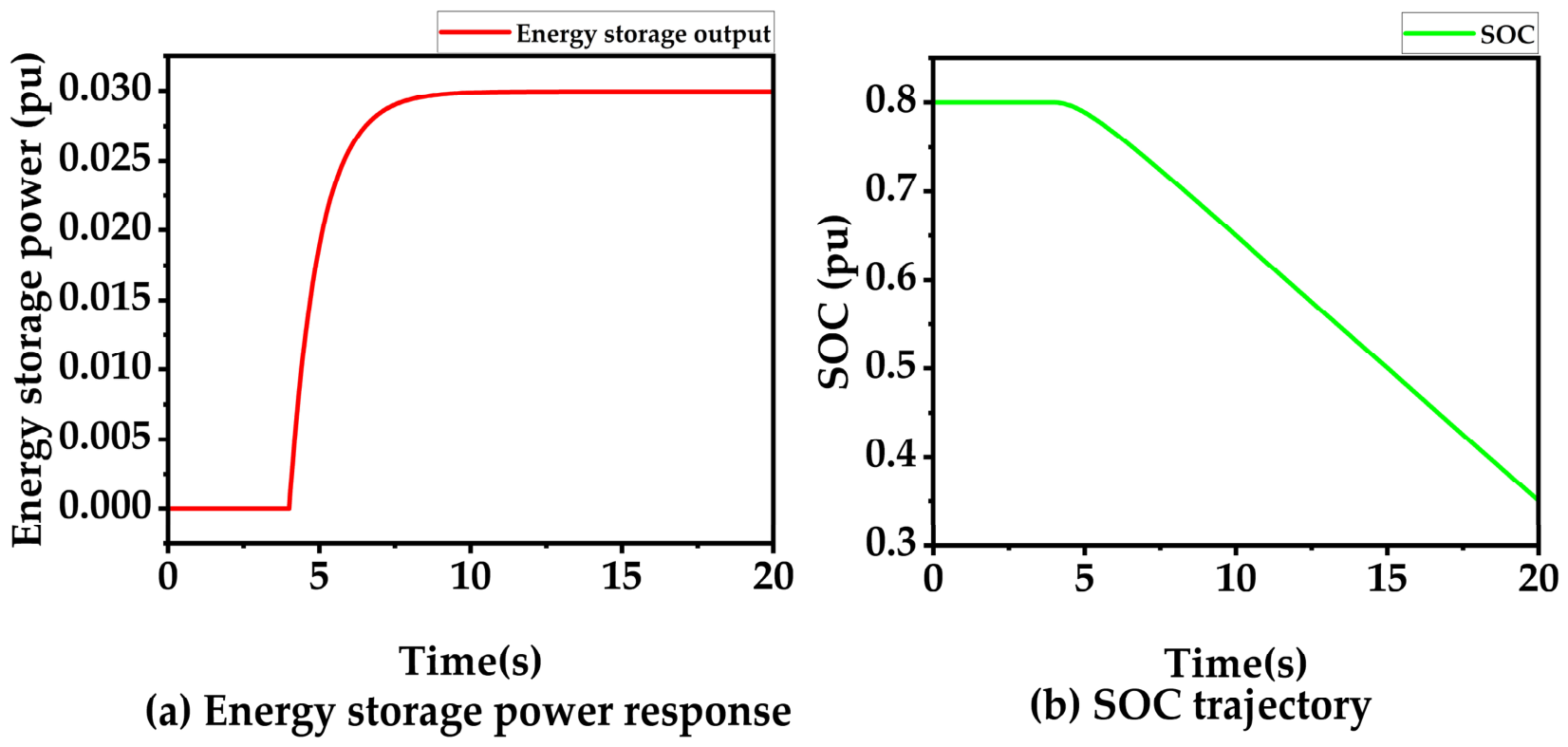
Figure 10.
Comparison of primary frequency responses under different control strategies and wind power penetration levels.
Figure 10.
Comparison of primary frequency responses under different control strategies and wind power penetration levels.
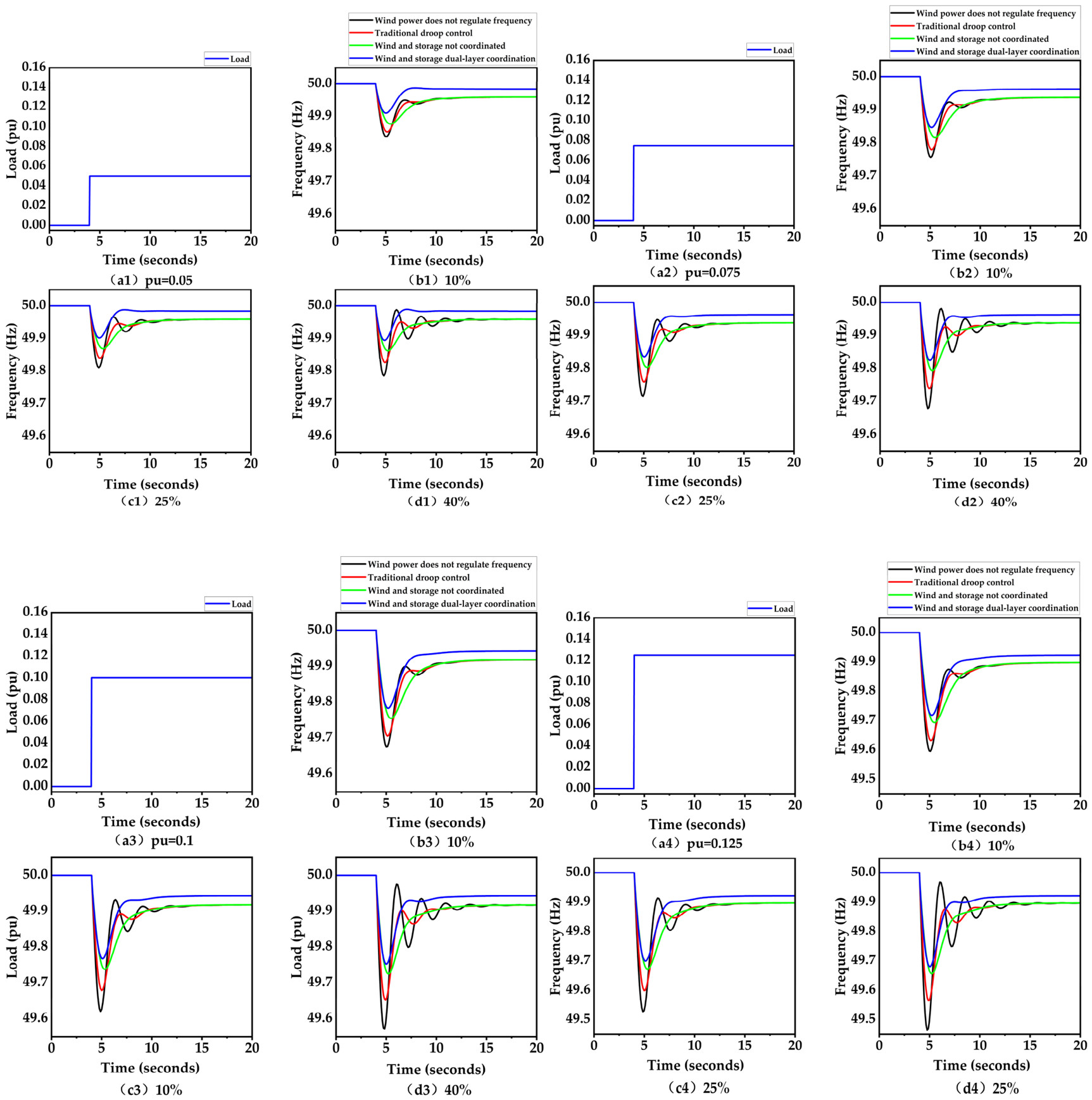
Figure 11.
Comparison of wind–storage frequency responses under different wind speed conditions.
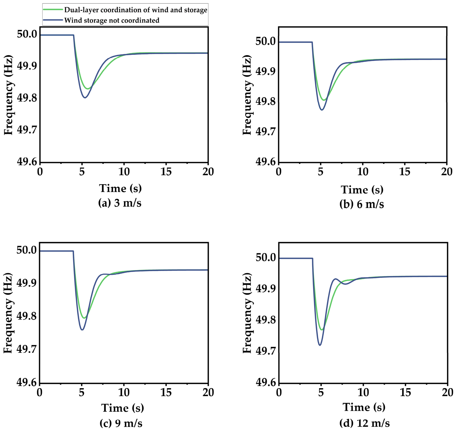

Table 1.
Main capacity and operating-condition parameters of the simulation system.
| Parameter | Value |
| Equivalent system base capacity | 100 MW |
| Nominal system frequency | 50 Hz |
| Wind power penetration | 10%, 25%, 40% |
| Installed wind power capacity | 10 , 25 , 40 MW |
| Rated BESS power | 10 MW |
| Rated BESS energy capacity | 5 MWh |
| Load disturbance magnitude | 0.05, 0.075, 0.10, 0.125 pu |
| Wind speed | 3, 6, 9, 12 m/s |
| Disturbance application time | 4s |
Table 2.
Primary frequency regulation performance under different wind speed conditions.
| Wind Speed (m/s) | Control Strategy | Frequency Nadir (Hz) | Frequency Drop (Hz) | Time to Nadir (s) | Maximum RoCoF (Hz/s) |
| 3 | Uncoordinated wind–storage control | 49.803 | 0.197 | 5.37 | 0.397 |
| Proposed hierarchical control | 49.831 | 0.169 | 5.62 | 0.330 | |
| 6 | Uncoordinated wind–storage control | 49.775 | 0.225 | 5.14 | 0.594 |
| Proposed hierarchical control | 49.808 | 0.192 | 5.37 | 0.525 | |
| 9 | Uncoordinated wind–storage control | 49.761 | 0.239 | 5.10 | 0.724 |
| Proposed hierarchical control | 49.797 | 0.203 | 5.34 | 0.654 | |
| 12 | Uncoordinated wind–storage control | 49.721 | 0.279 | 4.87 | 1.386 |
| Proposed hierarchical control | 49.771 | 0.229 | 5.07 | 1.312 |
Disclaimer/Publisher’s Note: The statements, opinions and data contained in all publications are solely those of the individual author(s) and contributor(s) and not of MDPI and/or the editor(s). MDPI and/or the editor(s) disclaim responsibility for any injury to people or property resulting from any ideas, methods, instructions or products referred to in the content. |
© 2026 by the authors. Licensee MDPI, Basel, Switzerland. This article is an open access article distributed under the terms and conditions of the Creative Commons Attribution (CC BY) license.
Copyright: This open access article is published under a Creative Commons CC BY 4.0 license, which permit the free download, distribution, and reuse, provided that the author and preprint are cited in any reuse.


