

Submitted:
19 July 2026
Posted:
21 July 2026
You are already at the latest version
Abstract
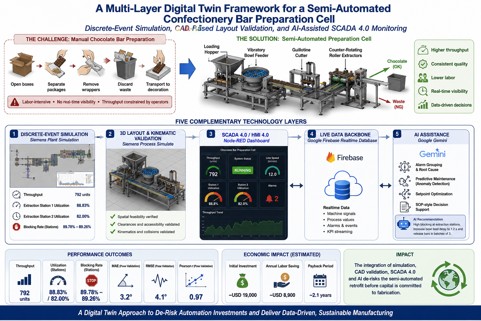
This paper presents a semester-long engineering project that develops a multi-layer Digital Twin for the chocolate-bar preparation stage, a bakery producer in Monterrey, Mexico. In the current process, operators manually open shipping boxes, separate multi-bar packages, peel individual wrappers, discard packaging waste, and transport exposed bars to a downstream decoration station with labor-intensive activity with no real-time visibility into throughput, cycle time, or quality events. We propose a compact, inline semi-automated preparation cell a loading hopper, vibratory bowl feeder, food-grade conveyor, pneumatically actuated guillotine cutter, counter-rotating roller extractors, and separated collection paths for product and waste and validate it across five complementary technology layers: (1) discrete-event simulation in Siemens Tecnomatix Plant Simulation; (2) 3D spatial and kinematic validation in Siemens Process Simulate with CAD solid models; (3) a Node-RED operator dashboard; (4) a Google Firebase Realtime Database as the shared live data backbone; and (5) Google Gemini for alarm grouping, predictive maintenance, setpoint optimization, and SOP-style decision support. The simulation sustains a conveyor output of 792 units over the modeled horizon, with extraction-station utilization of 88.83% and 82.00% and blocking rates approaching 89.78–89.26%, indicating that buffer and release-logic tuning is required before physical deployment. CAD-based validation confirms the station's spatial and kinematic feasibility, and the SCADA/HMI/AI layer demonstrates functioning live monitoring and AI-generated operational guidance. A preliminary economic analysis estimates an initial investment near USD 19,000, an annual labor saving near USD 8,900, and a payback period of approximately 2.1 years. The results indicate that discrete-event simulation, CAD validation, and SCADA 4.0/AI integration can jointly de-risk a semi-automated retrofit before capital is committed to fabrication.
Keywords:
digital twin
; discrete-event simulation
; Siemens plant simulation
; process simulate
; SCADA 4.0
; HMI 4.0
; Node-RED
; firebase
; Gemini AI
; ISA-95
; automation pyramid
; semi-automated packaging cell
I. Introduction
This study was developed in a bakery producer based in Monterrey, Nuevo León, Mexico, whose output includes cakes, desserts, and the preparation of specialty ingredients at industrial scale. Among its repetitive pre-production tasks, the handling of chocolate bars prior to cake decoration is a recurring labor bottleneck. The complete preparation sequence requires operators to open shipping boxes, separate multi-bar grouped packages, individually remove wrappers, discard packaging waste, and transport the extracted chocolate to the downstream decoration station.
In isolation this task appears trivial; at production scale, when hundreds or thousands of bars must be processed per batch, it becomes a material production constraint. Because the activity is manual, throughput is coupled directly to operator speed, fatigue, shift consistency, and individual technique. There is currently no real-time measurement of how many bars have been processed, how long each cycle takes, when upstream accumulation is building, or when quality-affecting events such as deformation or contamination occur. The absence of digital visibility makes continuous improvement difficult, since there is no process data to analyze.
The engineering significance of the problem therefore extends beyond labor cost: the process represents a gap in the data architecture of the production floor a critical input-preparation step that is invisible to any monitoring system. This project addresses both physical inefficiency and the monitoring gap through a Digital Twin that couples a semi-automated mechanical concept with discrete-event simulation, 3D spatial validation, SCADA 4.0 monitoring, and artificial intelligence.
A. Objectives
- Conduct a structured analysis of the current manual chocolate preparation process and quantify the principal sources of manual workload, cycle-time variability, operator dependency, and downstream bottleneck behavior.
- Develop a semi-automated preparation-cell concept capable of feeding, orienting, opening, extracting, and separating chocolate and packaging waste with reduced operator intervention.
- Build a Siemens Tecnomatix Plant Simulation model to evaluate throughput, station utilization, blocking rate, work-in-process accumulation, and output behavior under the proposed automation scenario.
- Validate the proposed station layout and principal equipment spatial relationships through Siemens Process Simulate and CAD solid models, confirming physical feasibility, operator access, and primary kinematic motion.
- Integrate SCADA 4.0, HMI 4.0, a Firebase Realtime Database, Node-RED, and Gemini to demonstrate live monitoring, alarm management, predictive maintenance, setpoint optimization, and operator decision support.
B. Scope
The project scope covers the chocolate preparation stage from the arrival of grouped multi-bar packages at the production area to the final separation of extracted chocolate product and discarded packaging waste, including loading-hopper design concept, package orientation, conveyor transfer, guillotine cutting, roller extraction, guide-chute routing, and container collection. The Digital Twin scope encompasses discrete-event simulation, 3D layout and motion validation, live SCADA/HMI dashboards, Firebase data architecture, and Gemini integration.
The scope explicitly excludes downstream cake-decoration operations; detailed mechanical fabrication drawings and tolerancing; food-contact hygienic certification (3-A, EHEDG); electrical panel and safety-circuit design; regulatory compliance verification; complete machine commissioning and acceptance testing; and prototype fabrication. These items are identified as the logical next development stage following simulation and conceptual validation.
II. System Description
A. Baseline Manual Process
The baseline system is a fully manual preparation workflow. Product arrives at the production area as shipping boxes containing grouped chocolate multi-bar packages, each holding six individual 48 g bars. Operators open the boxes, remove the grouped packages, separate individual packages, peel or tear the wrapper material, discard the packaging waste, and transport the exposed bars to the decoration station for further processing.
This workflow is inherently batch-oriented: operators process one or several bars at a time and accumulate products in trays or containers before downstream handoff. There is no fixed cycle time, no continuous flow, no product tracking, and no automatic detection of jams, deformation events, or waste accumulation, so performance depends entirely on individual operator technique, fatigue management, and shift schedule. As shown in Figure 1, the Plant Simulation representation of the baseline system captures this structure through manual worker resources, sequential work areas, and unconstrained output accumulation.
Figure 1.
Plant Simulation representation of the current manual chocolate preparation process.
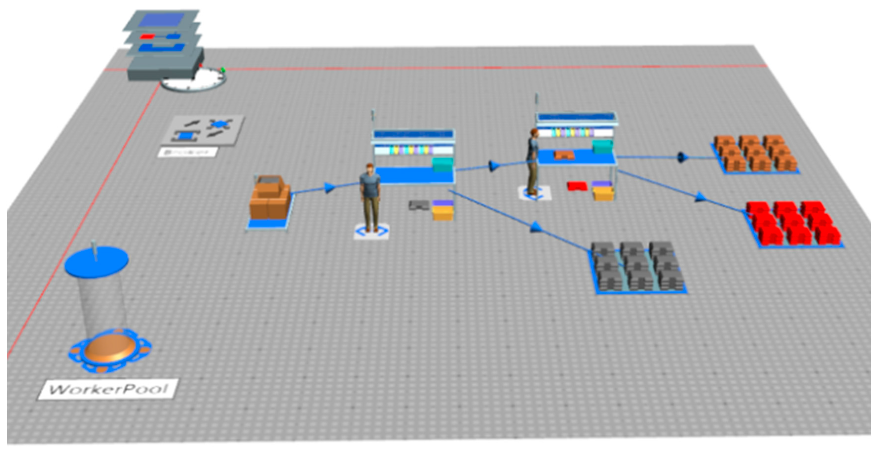

Table I.
Current process parameters used for baseline comparison.
| Parameter | Value | Engineering relevance |
| Bar weight | 48 g | Defines the unit handled by the operator and by the proposed opening/extraction system. |
| Package format | 6 bars per package, approx. 290 g | Establishes the input grouping that the hopper/feeder must handle. |
| Master case | approx. 9.3 kg | Represents the incoming production format and loading unit. |
| Opening batch | approx. 350 bars, approx. 17 kg | Defines the manual batch size used for comparison. |
| Opening time | approx. 30 min/batch | Baseline processing time for evaluating time-reduction potential. |
| Batches per shift | 2 batches per 12-hour shift | Defines the recurring production demand. |
| Operators | 2 | Baseline labor requirement before automation. |
| Partner target | 50% reduction in opening time | Performance objective for the proposed semi-automated system. |
Figure 2.
Clean flow diagram of the current manual chocolate preparation process.

B. Proposed Automated Cell
The proposed system transforms the batch manual operation into a compact, inline semi-automated preparation cell. The operator loads grouped packages into a vibratory bowl feeder or loading hopper. The feeder orients individual packages and releases them in a controlled, simulated stream onto a food-grade belt conveyor. The conveyor transfers each package to a guarded guillotine cutting station where a pneumatic actuator descends to open one end of the wrapper without contacting the chocolate bar. The opened package then advances to a counter-rotating roller extraction module, where controlled compression forces the bar free from the wrapper. Downstream guide chutes route the extracted bar to a food-safe product container and the empty wrapper to a dedicated waste bin. The operator role transitions from repetitive unwrapping to supervised loading, quality inspection, container management, and fault response, as shown in Figure 3.
C. Assumptions
Table II.
Modeling and engineering assumptions.
| Assumption | Engineering purpose |
| One chocolate package (six bars, 48 g each) is treated as one flow unit throughout the Plant Simulation model. | Simplifies throughput, output, and WIP tracking while maintaining consistency with the actual product format. |
| The proposed line follows a fixed, deterministic sequence: loading → feeding → conveyor → cutting → extraction → sorting. | Allows deterministic control logic, a clear validation path, and repeatable KPI measurement. |
| Manual operations in the baseline model are represented with operator processing times and single-worker resources. | Enables direct comparison of manual and semi-automated scenarios under equivalent simulation conditions. |
| The cutter opens exactly one end of each wrapper per cycle without deforming the chocolate bar. | Preserves product integrity and simplifies roller-extraction force requirements. |
| Extracted chocolate and empty wrappers are modeled as two separate objects after the extraction station. | Supports independent validation of product collection and waste discharge streams. |
| Sensor signals confirm product presence at critical positions before each actuator fires. | Reflects industrial control practice and is required for Plant Simulation logic validity. |
D. Constraints
The principal engineering constraints governing the design are: available floor space within preparation area; product fragility, requiring gentle handling to prevent deformation or breakage of the 48 g bar; food-contact hygiene standards mandating food-grade materials, smooth cleanable surfaces, and the absence of dead zones; packaging variability between production lots; operator safety, requiring physical guarding around the cutting and roller mechanisms with emergency-stop access; and investment feasibility, requiring a proposal realistic enough to be modeled and validated before committing fabrication resources.
The cutting and roller modules must open the wrapper without applying force to the chocolate surface, and waste must be physically separated from product to prevent cross-contamination. Safety interlocks must prevent cutter or roller actuation when the operator’s access zone is breached. These constraints were incorporated into the Process Simulate/CAD layout and into the control-logic architecture described in Section VI.
III. Methodology
The project followed a five-layer progressive Digital Twin methodology, advancing from process understanding to physical concept, then simulation, 3D validation, and finally live monitoring and AI integration. This structure ensures that each development decision is grounded in evidence from the preceding layer, and that the resulting Digital Twin is a coherent combination of production-behavior analysis, physical-feasibility validation, and operational data intelligence.
Layer 1 - Process Analysis. The current chocolate preparation sequence was documented through team observation, operator interviews, and timing estimation. Value-added and non-value-added activities were identified and mapped into a baseline simulation model to quantify existing performance without automation.
Layer 2 - Automation Concept Definition. Based on the process analysis, the team defined the functional requirements of the proposed cell and selected the principal equipment families: a vibratory bowl feeder [5], a food-grade belt conveyor [3], a pneumatic guillotine cutter [4], a counter-rotating roller extractor, guide chutes, and collection containers, each selected for functional suitability to food-grade packaging opening and extraction operations.
Layer 3 - Plant Simulation Modeling. The proposed cell was modeled in Siemens Tecnomatix Plant Simulation [1] as a discrete-event model. Both the baseline manual scenario and the semi-automated alternative were built to enable a direct performance comparison; the KPIs analyzed included throughput, utilization, blocking rate, waiting time, and WIP accumulation.
Layer 4 - Process Simulate / CAD Validation. The physical station was modeled and assembled using CAD solid models imported into Siemens Process Simulate [1]. The spatial arrangement was validated for operator ergonomics, equipment clearances, feeding alignment, cutter approach, and roller-extraction geometry, and primary kinematic motions were confirmed as conceptually feasible within the station footprint.
Layer 5 - SCADA 4.0 / AI Integration. A JavaScript virtual-PLC simulator generates live process values representing the operational state of each station. These values are written to a Google Firebase Realtime Database [8] structure; Node-RED [7] reads the Firebase data at a configurable polling interval and renders a multi-page operator HMI dashboard; and Gemini [9] is integrated to analyze selected live variables and generate human-readable operational recommendations, following the SCADA 4.0 paradigm.
Table III.
Digital Twin development layers and tools.
| Layer | Tool / resource | Purpose in project |
| 1 - Process Analysis | Team observation, timing, documentation | Establish baseline behavior and identify bottlenecks |
| 2 - Automation Concept | Engineering analysis, equipment selection | Define cell functional requirements and component families |
| 3 - Discrete-Event Model | Siemens Tecnomatix Plant Simulation [1] | Evaluate throughput, utilization, blocking, WIP, and cycle time |
| 4 - 3D / Layout Validation | Siemens Process Simulate + CAD [1] | Validate station geometry, operator access, and kinematic feasibility |
| 5 - SCADA 4.0 / AI | Node-RED [7], Firebase [8], Gemini [9] | Provide live monitoring, alarms, predictive maintenance, and AI recommendations |
IV. Plant Simulation Development
Siemens Tecnomatix Plant Simulation [1] was selected as the discrete-event simulation environment because it provides object-oriented modeling of material flow, resource allocation, station logic, conveyor behavior, and statistical output analysis within a single integrated environment. The simulation development addressed both the manual baseline scenario and the proposed semi-automated alternative, enabling a structured comparison of production performance before and after the automation proposal.
A. Model Architecture
The baseline model captures the manual work environment using Worker resources, Workplaces, Buffers, and Output stores. Material objects representing individual chocolate packages move from a Source through a manual processing station where a Worker resource controls processing time; waste and product accumulate in output areas without separation, reflecting the actual manual process structure.
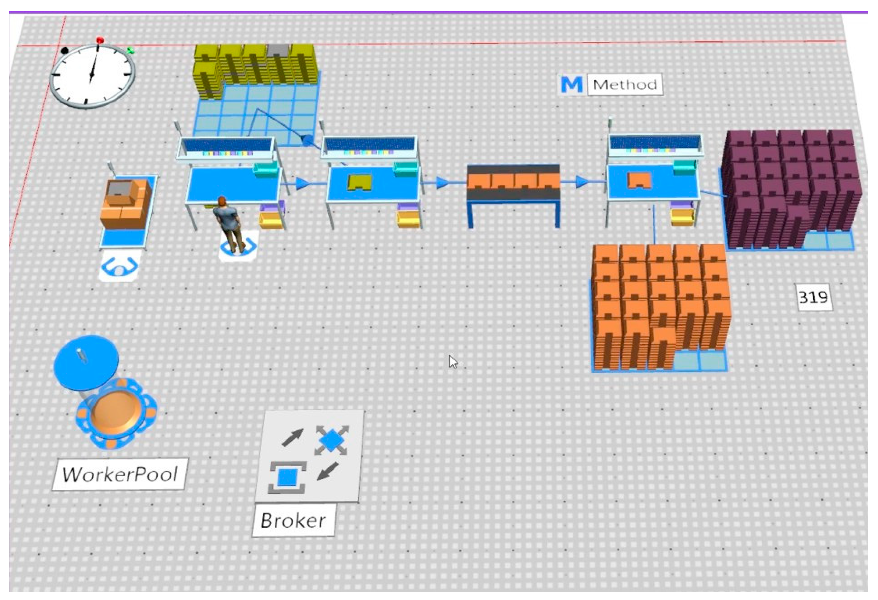
The proposed semi-automated model adopts a machine-centric architecture. Source objects generate packages at a controlled rate corresponding to the hopper/feeder output; a Buffer object upstream of the first station represents the loading hopper and regulates arrival rate; a Conveyor object models the physical belt transfer; processing stations (Workplaces or SingleProcs) represent the cutting and extraction operations with defined processing times and capacity; and a Dismantling Station separates the incoming object into two outputs the chocolate bar (routed to a product Store) and the empty wrapper (routed to a waste Drain). This architecture separates material flow from resource logic: objects represent product units, stations represent transformation capacity, and workers represent human intervention only where required (loading, fault response).
Figure 4.
Plant Simulation representation of the proposed semi-automated chocolate preparation process, showing Source, Buffer/Hopper, Conveyor, CuttingStation, and DismantleStation objects, the product Store, and the waste Drain.
Figure 4.
Plant Simulation representation of the proposed semi-automated chocolate preparation process, showing Source, Buffer/Hopper, Conveyor, CuttingStation, and DismantleStation objects, the product Store, and the waste Drain.
B. Process Flow
The simulated process flow begins with package generation at the Source object, which releases objects at a rate calibrated to the expected feeder output. The upstream Buffer (hopper) regulates release and provides a controlled queue to prevent direct source overload of the conveyor, which transports packages at a defined belt speed toward the first processing station.
The CuttingStation represents the guillotine mechanism and models the cutting cycle time, including approach, dwell, and retract phases. After cutting, the package advances to DismantleStation1, which separates the object into the chocolate-bar entity (directed to the product Store) and the wrapper entity (directed to the waste Drain). A second DismantleStation2 models an alternative or redundant extraction stage and handles overflow or parallel processing. Output Store objects accumulate product count throughout the simulation run, providing the primary throughput metric.
C. Resources
The primary modeled resources are: Source (package generator); Buffer/Hopper (upstream queue and release controller); Conveyor (belt transfer with configurable speed); CuttingStation (SingleProc with a defined cutting cycle time); DismantleStation1 and DismantleStation2 (extraction resources with output routing to the Store and Drain); the product Store (chocolate accumulator); the waste Drain (wrapper-disposal counter); and Worker (human resource for loading and fault response). This distinction is critical because it separates mechanical process limitations (conveyor speed, cutting cycle, extraction cycle) from human limitations (loading rate, response time), allowing the model to expose the true system bottleneck rather than conflating human and machine behavior.
D. Key Performance Indicators Analyzed
Table IV.
KPIs analyzed in Plant Simulation.
| KPI | Why it matters | Interpretation approach |
| Throughput / output | Measures the total number of valid product units exiting the system during the simulation horizon. | Primary metric for quantifying the production benefit of automation over the manual baseline. |
| Station utilization (%) | Measures the fraction of simulated time a resource is actively processing. | High utilization indicates productive use or a potential bottleneck; must be analyzed relative to blocking. |
| Blocked time (%) | Measures the fraction of time a station or source cannot release output due to downstream restrictions. | Identifies capacity mismatch and output-release deficiencies requiring buffer tuning. |
| Waiting time / WIP | Measures accumulation upstream of stations. | Indicates imbalance between feeding rate, processing capacity, and output release. |
| Cycle time per unit | Measures the total elapsed time from package entry to product collection. | Supports comparison between manual and automated scenarios and validates throughput targets. |
The final simulation results reported a cumulative conveyor output of 792 units over the modeled run horizon, with two major Store outputs of 700 and 700 units representing extracted chocolate and separated waste streams. DismantleStation1 showed a utilization of 88.83% and DismantleStation2 showed 82.00%, confirming that both extraction resources carry high workloads consistent with the target throughput. Blocking values of 89.78% at the Source and 89.26% at the principal dismantling station indicate significant downstream restriction, requiring buffer capacity and release-logic tuning before physical deployment; these values are discussed further in Section VII.
V. Process Simulate Development
Siemens Process Simulate [1] and CAD solid models were used to validate the physical side of the proposed preparation cell. While Plant Simulation answers how many units the system can produce and where flow restrictions occur, Process Simulate and CAD answer whether the proposed equipment can be physically arranged into a buildable station with correct geometric relationships, safe operator access, and feasible primary motions a distinction that matters because a simulation model can show efficient flow while the corresponding physical arrangement is geometrically infeasible or unsafe.
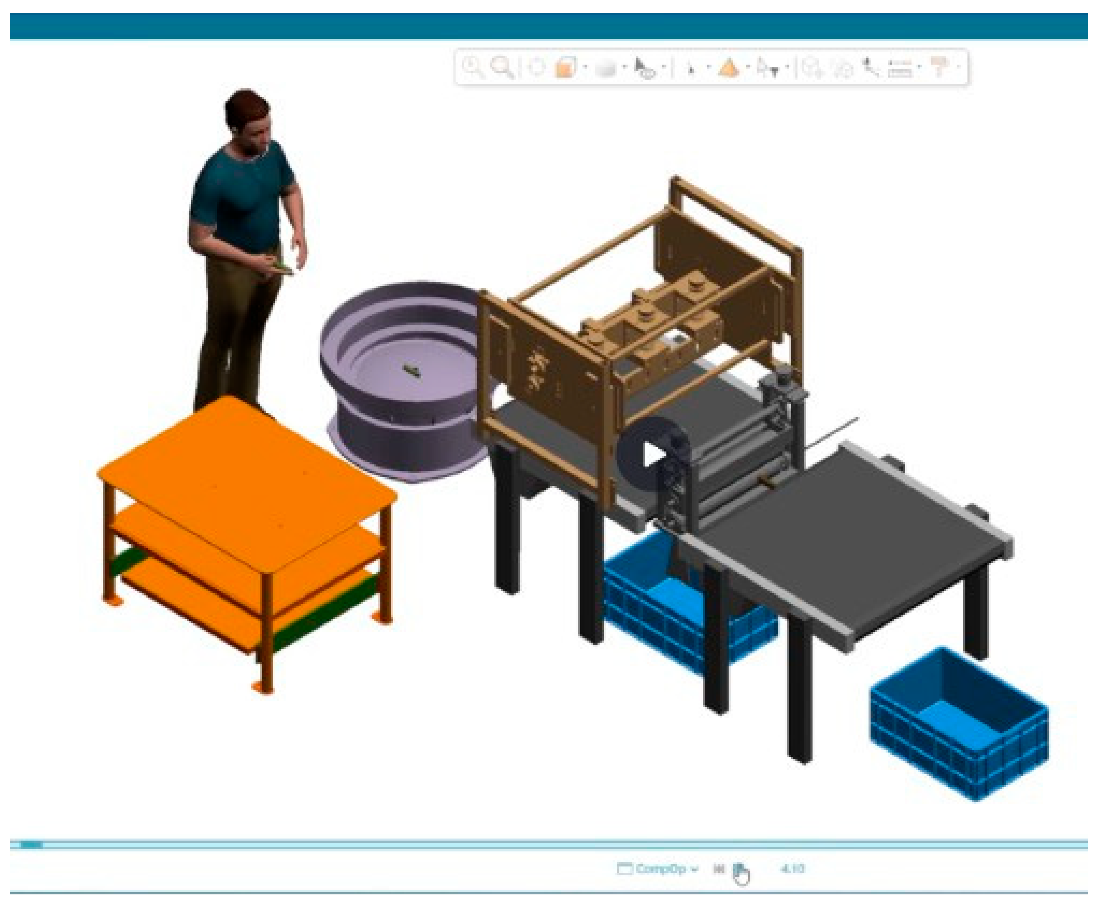
Figure 5.
Full Process Simulate/CAD view of the proposed semi-automated chocolate preparation station.
Figure 5.
Full Process Simulate/CAD view of the proposed semi-automated chocolate preparation station.
A. Station Layout
The station was organized as a compact inline cell following a left-to-right material flow direction. The loading table and vibratory bowl feeder [5] are positioned at the upstream (left) end so the operator can replenish material without entering the guarded cutting or extraction zone. The conveyor [3] runs centrally through the station and provides the controlled transfer surface between feeder output and the processing modules. The guarded cutter and roller-extraction section are grouped in the central processing zone, separated from operator reach by physical guards and interlocked access panels. Product and waste collection containers are positioned at the downstream (right) end, accessible for container exchange without approaching the processing zone.
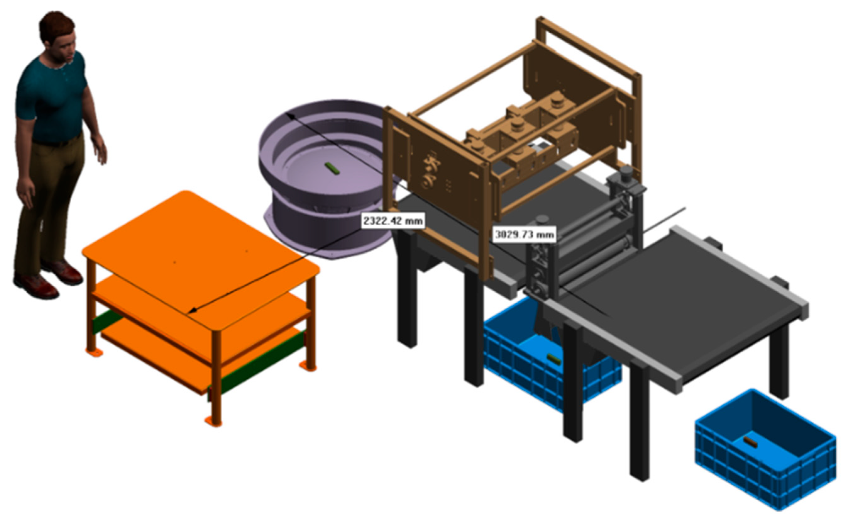
This arrangement satisfies three simultaneous requirements: a single continuous direction of material flow, which minimizes re-handling and prevents backtracking; adequate operator ergonomic clearance at the loading position (minimum 600 mm working space); and physical separation of the cutting/extraction hazard zone from routine operator interaction. The layout was validated dimensionally in Process Simulate/CAD to confirm that all requirements are met within a realistic floor-space envelope, as shown in Figure 7.
Figure 6a.
Detailed view of the cutter and counter-rotating roller-extraction area within Process Simulate, showing the package approach path and blade-descent geometry.
Figure 6a.
Detailed view of the cutter and counter-rotating roller-extraction area within Process Simulate, showing the package approach path and blade-descent geometry.
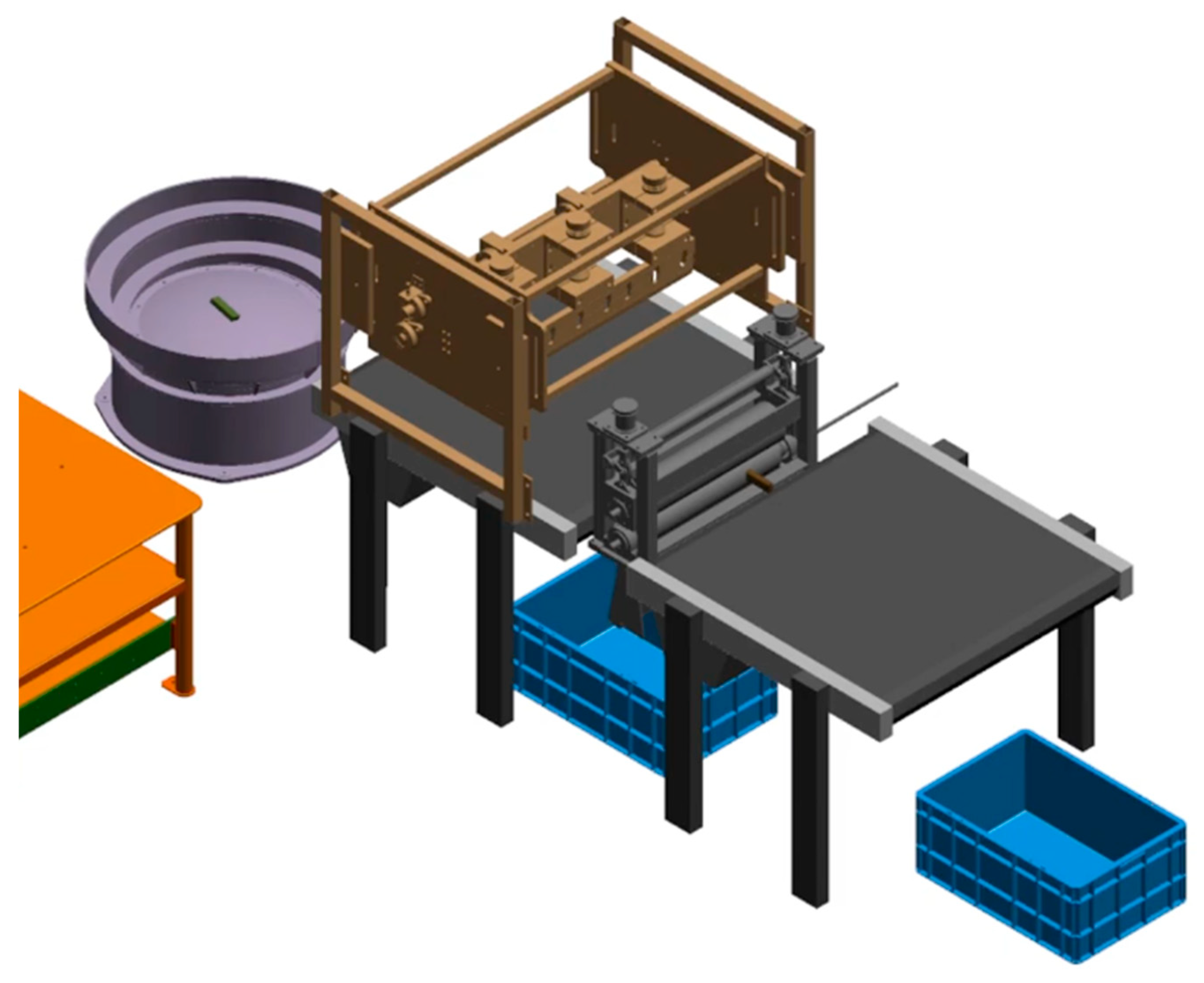
Figure 6b.
Roller-contact zone and guide-chute route to the separate product and waste containers.
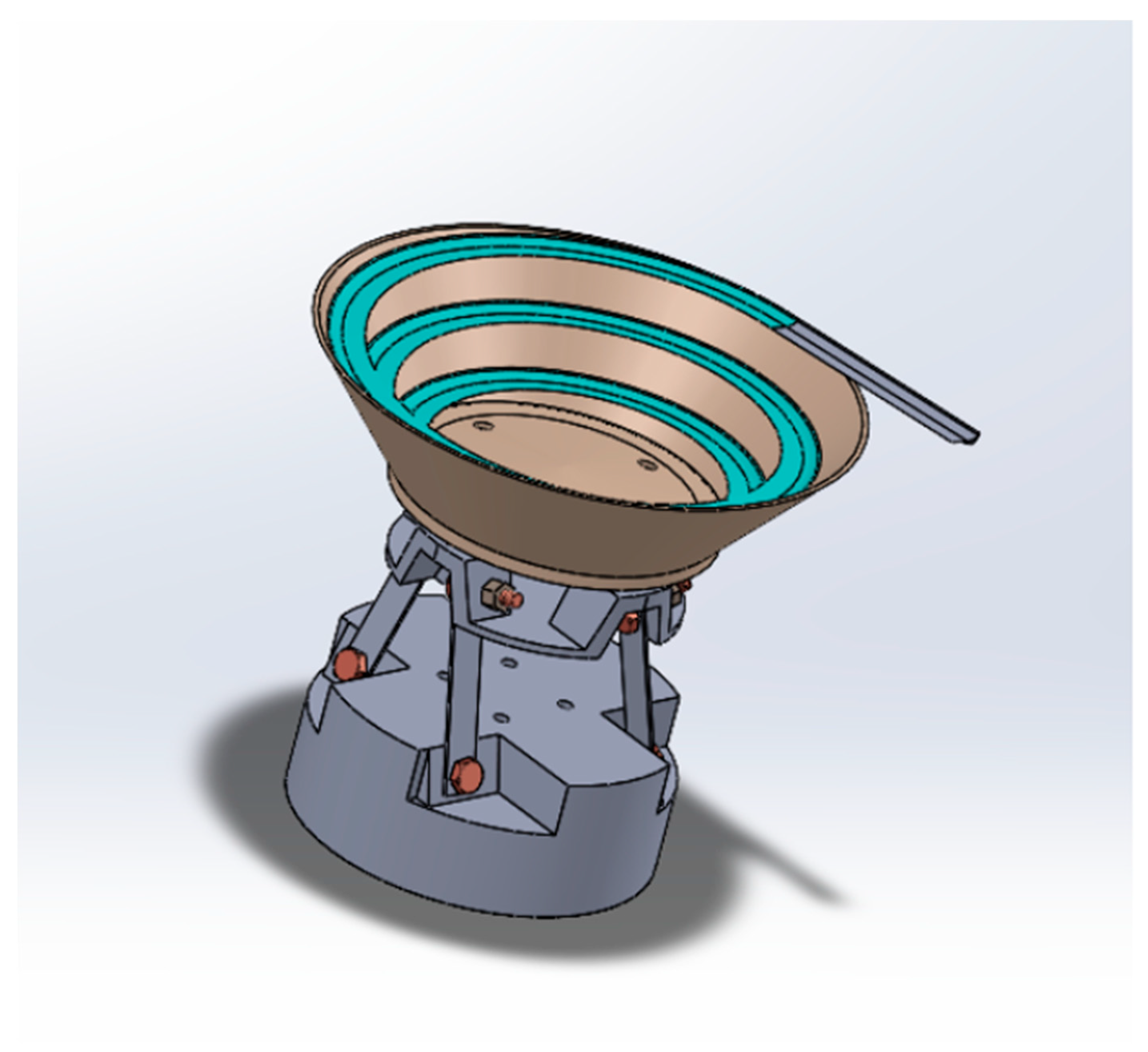
Figure 7.
Dimensional validation view used to confirm operator clearance and station spacing.
B. Equipment and Resources
The CAD evidence presents the principal equipment families incorporated into the proposed cell. Each family was selected based on functional suitability, availability of technical documentation, and food-contact compliance relevance.
Figure 8.
CAD reference of the primary feeding and conveying equipment: the Dorner AquaGard 7350 Series food-grade sanitary belt conveyor [3], selected for its hygienic design, tool-free belt removal, and positive-drive belt system, and the RNA Automation vibratory bowl feeder [5], selected for its adjustable vibration amplitude and compatibility with flexible packaging materials.
Figure 8.
CAD reference of the primary feeding and conveying equipment: the Dorner AquaGard 7350 Series food-grade sanitary belt conveyor [3], selected for its hygienic design, tool-free belt removal, and positive-drive belt system, and the RNA Automation vibratory bowl feeder [5], selected for its adjustable vibration amplitude and compatibility with flexible packaging materials.
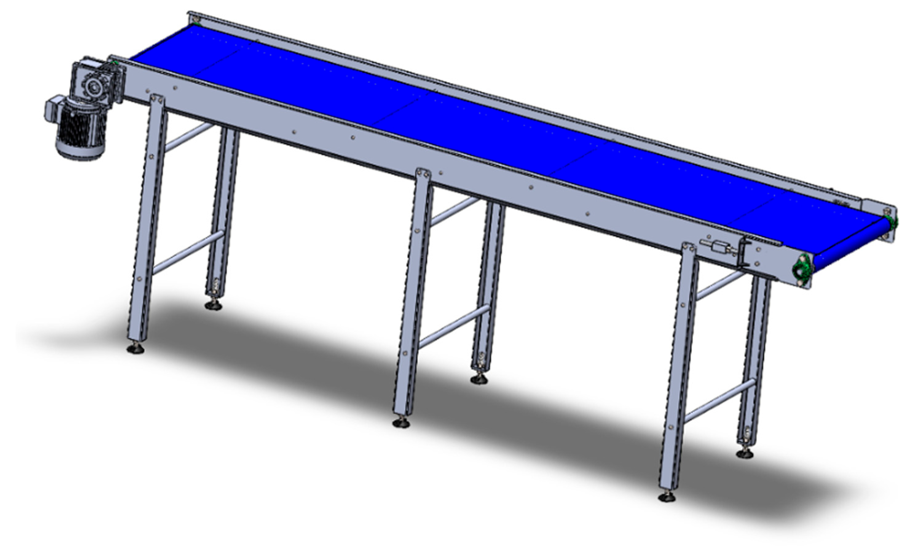
Figure 9.
CAD view of the guillotine cutter/extraction module, showing the Festo ADVU compact pneumatic cylinder [4] actuating the cutter blade, the protected mechanical frame, blade guide rails, and drive elements.
Figure 9.
CAD view of the guillotine cutter/extraction module, showing the Festo ADVU compact pneumatic cylinder [4] actuating the cutter blade, the protected mechanical frame, blade guide rails, and drive elements.
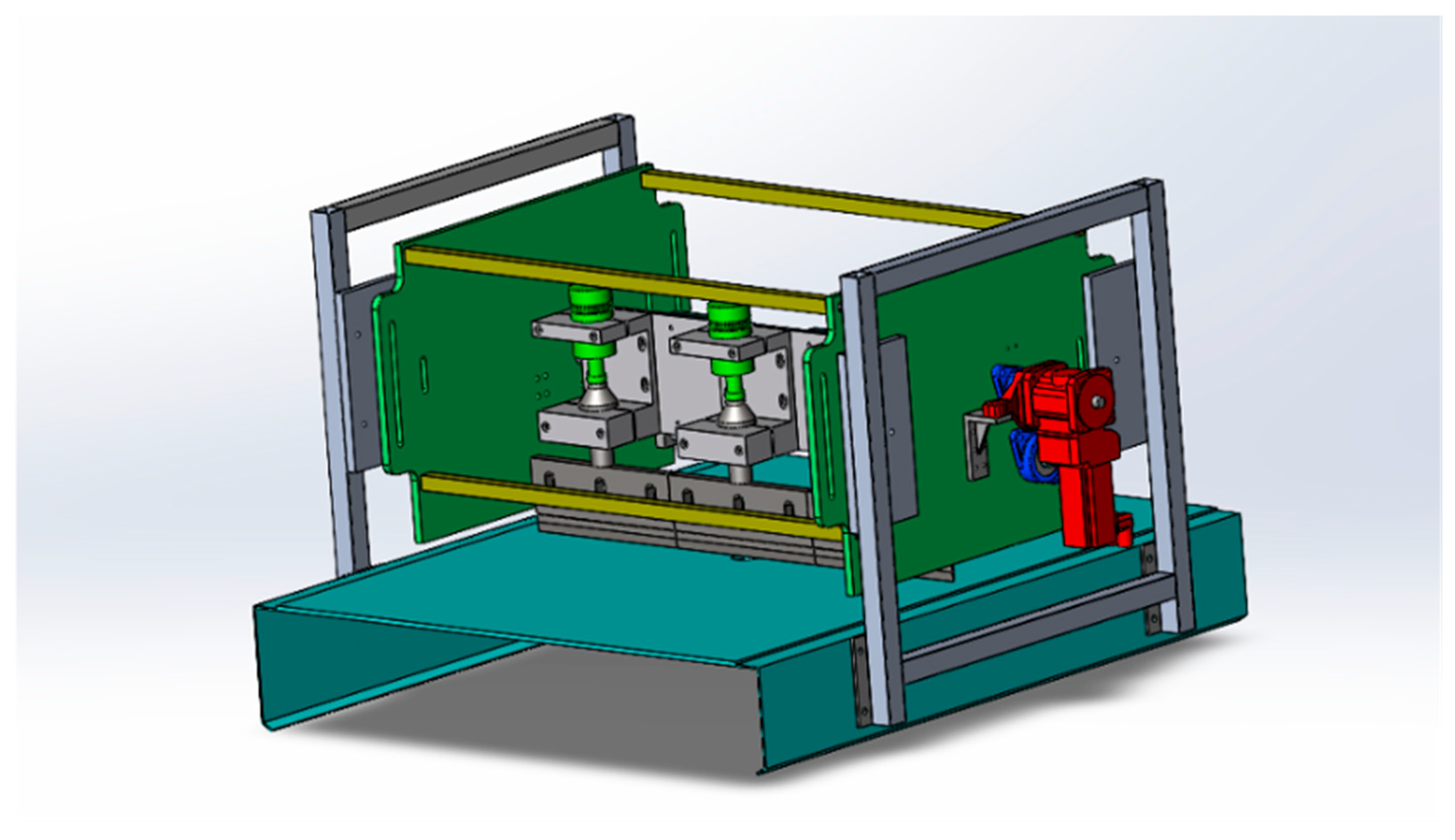
Figure 10.
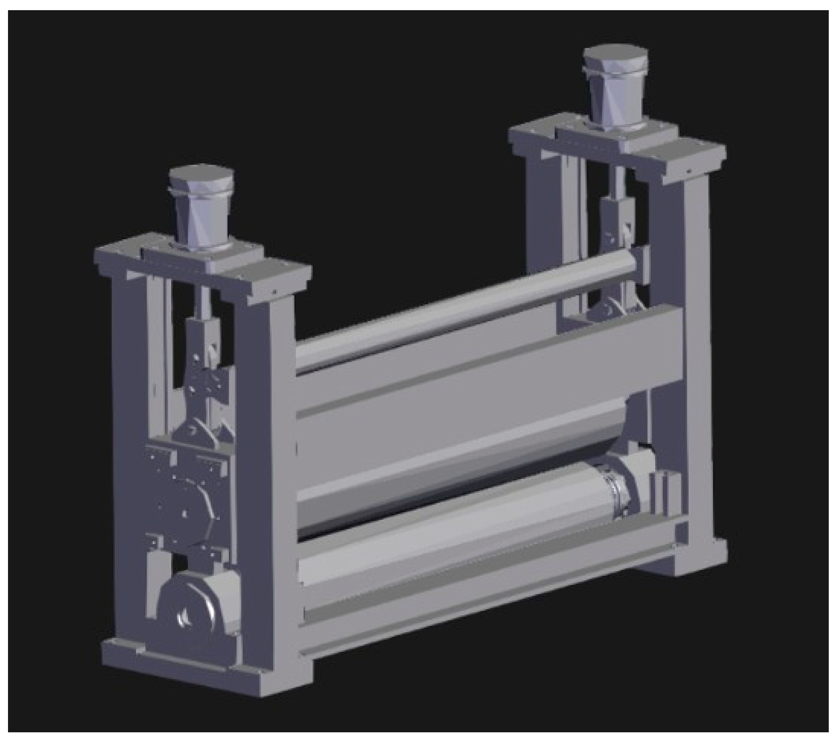
CAD reference of the counter-rotating roller extractor, illustrating the wrapper contact surfaces, adjustable roller gap for bar-diameter accommodation, and downstream guide chute for bar ejection into the product container.
Figure 10.
CAD reference of the counter-rotating roller extractor, illustrating the wrapper contact surfaces, adjustable roller gap for bar-diameter accommodation, and downstream guide chute for bar ejection into the product container.
C. Operations Sequence
- The operator loads grouped chocolate packages into the vibratory bowl feeder or loading hopper at the upstream end of the station.
- The bowl feeder orients and simulates individual packages through vibration-driven track geometry, releasing one package at a time onto the belt conveyor.
- A presence sensor (inductive or photoelectric) at the conveyor entry confirms that a package has been received and clears the conveyor motion interlock.
- The conveyor belt transports the package at controlled speed toward the cutter station; a second presence sensor at the cutter entry position triggers the cutter sequence when the package reaches the correct position.
The conveyor pauses (or indexes) while the Festo ADVU pneumatic cylinder [4] drives the guillotine blade downward to open one end of the wrapper with a single controlled stroke.
- The conveyor resumes and advances the open-ended package into the counter-rotating roller-extraction section.
- The rollers apply controlled radial compression to the wrapper surface, forcing the chocolate bar out of the open end and into the guide chute that routes it to the food-safe product container.
- The empty wrapper follows an adjacent guide chute into the waste collection bin.
- A downstream output sensor increments the cycle counter, updates the throughput variable in the Firebase data model, and clears the station for the next cycle.
D. Motion Validation and Kinematic Design
The principal motion relationships validated through the Process Simulate/CAD environment are: (1) linear continuous belt-conveyor motion at configurable speed; (2) vertical reciprocating linear cutter motion driven by the Festo ADVU pneumatic cylinder [4]; and (3) synchronized, bidirectionally opposed rotational roller motion creating a compressive nip zone for wrapper extraction.
The cutter motion requires repeatable vertical positioning to open the wrapper end without the blade contacting the chocolate surface; the blade-descent stroke is controlled by the cylinder stroke length and cushion setting, with a physical hard stop limiting penetration depth. The rollers require synchronized counterrotation at matched tangential surface speed, with an adjustable gap set slightly smaller than the nominal bar cross-section to generate sufficient compression without deformation. The feeder requires calibrated vibration amplitude and frequency to advance packages at the intended release rate without jamming in the bowl-track geometry.
Process Simulate/CAD validation confirmed that these motions are conceptually feasible within the proposed station geometry. Future work must include detailed actuator sizing calculations (cylinder bore, working pressure, force margin), roller drive-motor selection, gap-adjustment mechanism design, food-grade surface material specification, and safety interlock logic verification.
VI. SCADA and HMI 4.0, AI, and Technology Integration
The SCADA 4.0 and HMI 4.0 layer converts the simulation and layout proposal into an intelligent, observable Digital Twin. Following the ISA-95 enterprise-control integration standard [10] and the broader industrial automation pyramid, in which field-level sensors and actuators are aggregated at the supervisory (SCADA) level before reaching enterprise-level decision-making [6], the architecture provides a continuous data flow from the process level (sensor values, actuator states, counters) through the supervisory level (Firebase Realtime Database) to the human-machine interface level (Node-RED Dashboard) and the intelligence layer (Gemini recommendations). The result is a system in which the process is not only simulated and physically modeled but also represented in real time on an operator dashboard that provides actionable guidance.
A. System Architecture
The data flow begins with a JavaScript virtual-PLC simulator that generates realistic process-variable values at configurable update intervals, representing the live operational state of each station: bowl-feeder vibration frequency and jam count, conveyor belt speed and throughput counter, cutter blade position and cut force, cutter opening time and cut-precision metric, roller force and extraction success rate, and blade-wear accumulation. In a physical deployment, this virtual-PLC logic is intended to run on a SIMATIC S7-1200 programmable controller [2], the hardware platform reflected in the budget of Table VIII. The virtual PLC writes these values to a Google Firebase Realtime Database [8] structure organized hierarchically by station (bowlFeeder, conveyor, cutter, squeezeRollers).
Node-RED [7] reads the Firebase data at a configurable polling interval (nominally 5 s) through an HTTP request node connected to the Firebase REST API. The retrieved JSON is parsed and distributed to Node-RED Dashboard UI widgets gauges, level indicators, toggle switches, text blocks, and chart nodes. A separate Node-RED flow sends selected process variables to the Gemini API [9] and renders the AI response in a dedicated dashboard panel, as illustrated conceptually in Figure 12.
Figure 11.
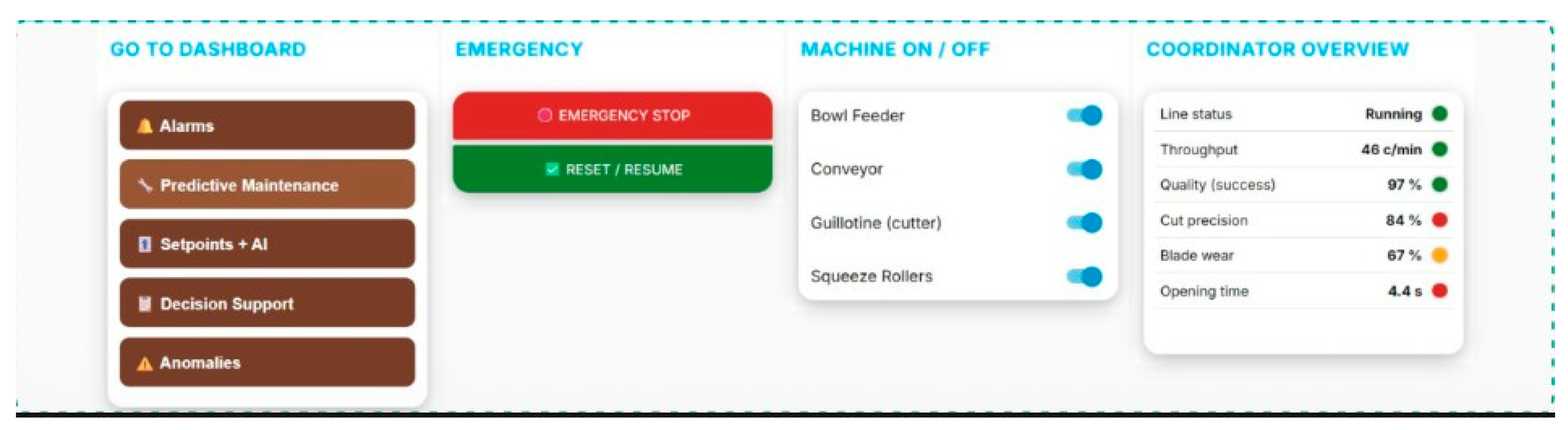
Node-RED HMI 4.0 dashboard showing the Coordinator Overview panel with machine control toggles.
Figure 11.
Node-RED HMI 4.0 dashboard showing the Coordinator Overview panel with machine control toggles.
B. Firebase Data Architecture
The Firebase Realtime Database structure was designed as a flat, stage-organized hierarchy to minimize read latency and simplify Node-RED parsing. The root node contains four station branches: bowlFeeder (feedRate, vibrationFreq, jamCount, motorStatus), conveyor (beltSpeed, throughput, unitCount, motorStatus), cutter (bladePosition, cutForce, openingTime, cutPrecision, bladeWear, successRate), and squeezeRollers (rollerForce, rollerSpeed, extractionSuccess, rollerGap). Each variable is a real-time scalar value updated by the virtual PLC simulator at every cycle interval.
Using a single shared data structure ensures that the HMI dashboard and the AI recommendation engine always read the same, temporally consistent snapshot of process state, preventing the inconsistencies that would arise from polling multiple independent data sources at different times. Firebase's built-in listener mechanism also allows future migration to a real-time push architecture using .on('value') listeners rather than polling, which would further reduce latency in a physical implementation.
C. HMI 4.0 Interface Design
The Node-RED Dashboard is organized around operator-centric usability, a core requirement of HMI 4.0 design philosophy, with five navigation pages accessible from a persistent menu: Home (machine control and coordinator overview), Alarms (active alarm list with severity and grouped root-cause analysis), Predictive Maintenance (blade-wear trending, remaining-life estimation, and maintenance scheduling), Setpoints + AI (speed and gap setpoint entry fields plus the Gemini recommendation panel), and Anomalies (recent abnormal-event log with timestamps and suggested actions).
The Home page includes an Emergency Stop button (hard-coded red with confirmation), a Reset/Resume control, and On/Off toggles for each station. Its Coordinator Overview panel displays the six most critical process KPIs as gauges and text indicators throughput rate (units/min), extraction success rate (%), cut precision (%), blade-wear accumulation (%), average opening time (s), and conveyor belt speed (m/min) so an operator can assess overall process status in a single glance without navigating multiple pages.
D. AI Functions and SCADA 4.0 Pillars
Table V.
SCADA 4.0 AI functions and operational value.
| SCADA 4.0 pillar | Implemented function | Operational value |
| Alarm management / anomaly detection | Groups repeated abnormal opening-time events and identified the likely root cause (mechanical obstruction, blade misalignment, worn guide), reducing the alarm list to a single grouped alarm with numbered corrective actions. | Eliminates alarm fatigue caused by repetitive individual events; helps the operator respond to the underlying cause rather than isolated symptoms, reducing mean time to restore (MTTR). |
| Predictive maintenance | Tracks cumulative blade-wear rate (% per 100 cycles) and calculates remaining operating minutes before the sharpening threshold is reached, displaying a countdown and recommended maintenance window. | Enables planned blade maintenance before poor cut quality begins generating product waste; converts reactive maintenance to a proactive, data-driven schedule. |
| Setpoint optimization | Reads current conveyor speed and extraction success rate from Firebase and calls the Gemini API with a structured prompt, returning a specific numerical speed recommendation with rationale. | Balances throughput and quality without requiring the operator to manually interpret correlation data; prevents over-optimizing speed until quality degrades. |
| Decision support / SOP | Translates live process conditions into a numbered, prioritized list of operator actions formatted as an on-screen standard operating procedure, updated with every Gemini API call. | Makes the system actionable for production operators, not only engineers; reduces decision latency and error probability during abnormal conditions or process transitions. |
E. Digital Twin Integration and ISA-95 Alignment
The integrated system realizes the Digital Twin concept by connecting the five technology layers into a closed information loop. Plant Simulation provides production-behavior evidence and bottleneck identification that inform the engineering control logic; Process Simulate/CAD validates that the physical station can support the control sequence identified in simulation; Firebase provides the shared live data model connecting the virtual PLC, the HMI, and the AI layer; Node-RED renders actionable information from that data model; and Gemini adds interpretive intelligence that converts raw process values into human-readable guidance. This architecture aligns with the ISA-95 hierarchy [10] by connecting the manufacturing process level (sensor values) to the supervisory control level (Firebase/SCADA) and the operations management level (HMI decisions and AI recommendations).
VII. Results
The results validate the engineering proposal at three independent levels: (1) process performance from Plant Simulation, quantifying throughput, utilization, blocking, and output behavior; (2) physical feasibility from Process Simulate/CAD, confirming station layout, spatial relationships, and kinematic motion; and (3) monitoring capability from the SCADA/HMI/AI implementation, demonstrating live data display, alarm grouping, predictive maintenance, and AI-generated recommendations.
A. Plant Simulation Results
The most important engineering insight from these results is not simply that the automated system produces units, but that it also reveals where design refinements are required before physical implementation. The high source blocking rate (89.78%) indicates that the proposed source generation rate exceeds the downstream processing capacity defined by the DismantleStation cycle times not a failure of the automation concept, but precisely the type of capacity mismatch that discrete-event simulation is designed to reveal before fabrication. The recommended corrective action is to either reduce the source generation rate (adjust feeder amplitude/frequency) or increase extraction capacity (shorten cycle time, add a parallel extraction station, or implement a pre-extraction buffer). This confirms that Plant Simulation provides engineering decision support that would otherwise require a physical prototype and multiple costly trial iterations.
Table VI.
Plant Simulation results summary.
| Metric / evidence | Reported result | Engineering interpretation |
| Conveyor output | 792 units | The semi-automated line sustains a significant continuous output over the simulated horizon, validating the feasibility of automated flow continuity. |
| Product Store output | 700 units | 700 extracted chocolate bar objects reached the product accumulation store, demonstrating successful extraction and routing separation. |
| Waste Store / Drain output | 700 units | 700 wrapper objects reached the waste disposal outlet, confirming that the DismantleStation logic correctly splits product from waste in every completed cycle. |
| DismantleStation1 utilization | 88.83% | The primary extraction station is heavily utilized, indicating high productive use; combined with its blocking rate, it is also the system's principal capacity constraint. |
| DismantleStation2 utilization | 82.00% | The secondary extraction resource carries a high but slightly lower workload, suggesting the two-station architecture provides modest capacity redundancy. |
| Source blocked time | 89.78% | The source is blocked for nearly 90% of the simulation horizon, indicating that downstream processing capacity cannot absorb the potential source generation rate; buffer tuning is required. |
| DismantleStation blocked time | 89.26% | The extraction station is blocked for most of its non-processing time, indicating that the output Store or Drain is the actual downstream restriction in the current model configuration. |
| HMI coordinator KPIs (live) | Values taken in real time from a PLC simulation, refreshed every 2 s | The HMI dashboard successfully translates raw Firebase values into a real-time operational-status view accessible to the production operator. |
B. Process Simulate / CAD Results
The Process Simulate/CAD validation confirmed that the proposed station components loading table, bowl feeder, conveyor, cutter module, roller extractor, guide chutes, and collection containers can be arranged within a realistic, compact inline-cell footprint. The dimensional validation view (Figure 7) confirmed that the minimum operator clearance of 600 mm is maintained at the loading end, and that the guarded processing zone creates a physical boundary between the operator access area and the cutting/extraction mechanisms. Primary kinematic motions (linear cutter descent, roller rotation, belt conveyor motion) were confirmed as geometrically compatible and non-conflicting within the assembled station layout.
C. SCADA / HMI / AI Results
The SCADA/HMI/AI implementation demonstrated successful real-time monitoring capability. The Node-RED dashboard displayed all six coordinator KPIs (throughput rate, success rate, cut precision, blade wear, opening time, belt speed) refreshing from Firebase at the configured polling interval. The Gemini integration generated contextually appropriate responses to four distinct operational conditions: repeated abnormal opening time (alarm-grouping response), blade wear approaching threshold (predictive-maintenance response), suboptimal speed-quality correlation (setpoint-optimization response), and a multi-condition abnormal state (SOP-style decision support). These results validate the SCADA 4.0 architecture as functional and operationally relevant to the proposed preparation cell.
VIII. Proposed Improvements
The simulation and validation results identify several engineering dimensions requiring improvement before the proposed cell can advance from a conceptual Digital Twin to a physical implementation. Improvements are organized by priority: flow-stability improvements (highest priority), sensing and control refinements (medium priority), and AI/SCADA enhancement (long-term priority).
A. Alternative Scenarios
Table VII.
Alternative improvement scenarios.
| Scenario | Description | Expected effect |
| Manual baseline (current) | Two operators perform box opening, package separation, wrapper removal, waste handling, and chocolate transfer manually for every production batch. | Lowest capital investment but highest labor dependency, throughput variability, and absence of real-time monitoring. |
| Semi-automated cell (proposed) | One operator loads and supervises while the hopper, conveyor, cutter, and roller extractor perform repetitive opening, extraction, and waste separation automatically. | Improves throughput continuity, reduces non-value-added manual handling, enables KPI measurement, and reassigns the operator to higher-value supervision. |
| Semi-automated cell with tuned buffers | Adds a controlled pre-cutter accumulation buffer and output containers sized to eliminate the source blocking and DismantleStation blocking identified in simulation. | Reduces source blocked time from 89.78% and station blocked time from 89.26% by absorbing rate mismatches; improves flow stability and reduces throughput loss. |
| Dual-extraction cell | Adds a parallel DismantleStation2 with its own roller set, reducing the load on the primary extraction resource from 88.83% to approximately 45–50% each. | Increases total extraction capacity, reduces utilization imbalance, and provides redundancy for maintenance events without production stops. |
| SCADA 4.0 + AI enhanced cell | Adds real-time Firebase data feed from physical sensors and a PLC, alarm grouping, predictive blade-wear maintenance, and speed-optimization recommendations. | Improves operational visibility, reduces alarm fatigue, converts reactive maintenance to proactive, and supports consistent operator response to repetitive events. |
B. Justification
The proposed improvements are justified in both engineering and operational grounds. From an engineering perspective, the simulation provides direct evidence of specific, measurable performance gaps: the 89.78% source blocking rate indicates a feeding-to-processing capacity mismatch that will limit actual production throughput unless corrected, and the 88.83% DismantleStation1 utilization combined with high blocking indicates that this station is simultaneously the system's highest-capacity resource and its primary downstream restriction a classic bottleneck signature requiring either cycle-time reduction or parallel capacity addition.
From an operational perspective, the improvements address the root causes identified throughout the analysis: manual labor dependency creates throughput variability; batch operation prevents continuous flow; the absence of live monitoring prevents data-driven improvement; and inconsistent alarm response increases mean time to restore. The proposed semi-automated cell with tuned buffers and SCADA 4.0 integration addresses all four root causes while keeping the human operator in the loop for tasks that genuinely require human judgment quality verification, product sampling, sanitation checks, and abnormal-condition response reflecting the operational reality of a food-production environment where complete unmanned automation is rarely appropriate or cost-effective at this scale.
C. Estimated Project Budget
The following preliminary budget connects the technical proposal to an implementation-level investment estimate. Values should be refined through supplier quotes but are detailed enough to support a first business case and demonstrate that the proposal is a moderate automation investment rather than a full robotic-replacement project.
Table VIII.
Estimated project budget.
| Component | Function | Estimated cost (USD) |
| RNA Automation vibratory bowl feeder | Feed and sort | approx. 4,500 |
| Dorner AquaGard sanitary belt conveyor | Package transfer | approx. 3,200 |
| Festo pneumatic cylinder + stainless-steel blade | Wrapper opening | approx. 2,000 |
| Leeson gearmotors + food-grade rollers | Chocolate extraction | approx. 2,500 |
| Siemens S7-1200 + HMI + sensors | Control and monitoring | approx. 3,800 |
| Design, commissioning, and training | Engineering support | approx. 3,000 |
| Total | approx. 19,000 |
D. Economic Justification and ROI
The proposal is economically attractive because the estimated investment of approximately USD 19,000 can be recovered through labor savings and operational control. By reducing the manual workload from two operators to one supervisor, the expected labor-related saving is approximately USD 8,900 per year, assuming a loaded labor cost near MXN 13,000 per month and an exchange rate near 17.5 MXN/USD. Under these conservative assumptions, the payback period is approximately 2.1 years (about 26 months).
Over a five-year horizon, accumulated savings are approximately USD 44,500; after subtracting the initial investment, the accumulated net benefit is approximately USD 25,500, producing an estimated five-year ROI near 134%. These figures exclude secondary benefits such as reduced scrap, lower operator fatigue, improved traceability, faster fault response, and higher throughput stability, so the realized business value may exceed the conservative estimate. For the proposal should therefore be evaluated not only as an automation expense but as productivity and process-control investment.
IX. Conclusions
This project demonstrates that the chocolate preparation process can be substantially improved through a multi-layer Digital Twin combining discrete-event simulation, 3D spatial validation, SCADA 4.0 monitoring, and AI-based decision support. The engineering contribution is not a single model or software tool, but the structured integration of simulation, mechanical design, real-time monitoring, data visualization, and intelligent decision support into a coherent proposal that addresses the current process from technical, operational, and economic perspectives.
Plant Simulation validated the production-flow concept and quantified the difference between the manual baseline which depends on manual opening, extraction, wrapper disposal, and transport by two operators and the proposed semi-automated cell, a continuous, measurable, and supervised line composed of a hopper and feeder, conveyor belt, mechanical cutter, and roller extractor. The results confirmed that the automated concept can sustain continuous output and generate measurable throughput, utilization, and blocking data that the manual process cannot produce, while also revealing that buffer sizing, output-release logic, and extraction capacity must be tuned together before physical implementation precisely the justification for simulating before investing in equipment.
Process Simulate and CAD evidence validated the spatial and kinematic feasibility of the proposed station: the loading table, bowl feeder, conveyor, cutter, roller extractor, guide chutes, and collection containers can be arranged into a compact, operator-accessible, directional-flow inline cell, with the principal motions (conveyor transport, package feeding, cutting, and roller extraction) confirmed as geometrically compatible providing a solid foundation for future detailed mechanical design and prototyping.
The SCADA 4.0, HMI, and AI implementation completed the Digital Twin by demonstrating that relevant process variables can be captured, transmitted to a live database, displayed on an operator dashboard, and analyzed by an AI engine capable of alarm grouping, predictive maintenance, setpoint optimization, and SOP-style decision support. This layer transforms the proposal from a mechanical automation concept into an observable, controllable, continuously improvable system, allowing the operator to monitor the line in real time and receive early recommendations before failures affect production.
From an economic perspective, the company should seriously consider this proposal: the estimated initial investment of approximately USD 19,000 is offset by projected annual labor-related savings of approximately USD 8,900, yielding a payback period near 2.1 years and additional long-term benefits reduced product waste, fewer errors from manual variability, better traceability, lower operator fatigue, improved throughput stability, and faster response to abnormal conditions that were not fully quantified in this analysis.
More broadly, the value of this proposal is that it does not simply replace labor with machinery; it changes the operator's role from repetitive manual execution to process supervision, quality verification, and decision-making gaining a more stable and measurable process without removing human control from a food-production operation and creating a platform for future improvements once the process is measured through SCADA/HMI and Digital Twin tools rather than observation alone.
Data Availability Statement
Supporting materials for this study — Plant Simulation and Process Simulate project files, CAD models, supplementary screenshots, and detailed engineering calculations — are available from the corresponding author upon reasonable request.
Acknowledgment
The authors thank the course faculty of Automation of Manufacturing Systems at Tecnológico de Monterrey, Campus Monterrey: Alejandra Molina-Leal, Antonio Carlos Bento, José Abraham Valdivia-Puga, Oliverio Hernández-Argumedo, Raquel Tejeda-Alejandre, Rubén Febronio García-Martínez - for their guidance throughout the project.
References
- Siemens AG, "Tecnomatix Plant Simulation and Process Simulate documentation," Siemens Digital Industries Software, 2024. [Online]. Available: https://www.siemens.com/global/en/products/automation/industry-software/tecnomatix.html.
- Siemens AG, "SIMATIC S7-1200 programmable controller: system manual," Siemens Digital Industries, 2024. [Online]. Available: https://support.industry.siemens.com/cs/attachments/109814829/s71200_system_manual_en-US_en-US.pdf.
- Dorner Conveyors, "AquaGard 7350 Series sanitary belt conveyors," product documentation, 2024. [Online]. Available: https://www.dornerconveyors.com/products/sanitary-stainless-steel-conveyors/aquagard-7350.
- Festo SE & Co. KG, "Compact cylinder, metric ADVU/AEVU," product catalogue, 2024. [Online]. Available: https://www.festo.com/us/en/p/compact-cylinder-metric-id_ADVU_AEVU/.
- RNA Automation Ltd., "Vibratory bowl feeders," product documentation, 2024. [Online]. Available: https://www.rnaautomation.com/products/feeding-and-handling/bowl-feeders/.
- RealPars, "What is the automation pyramid?," 2019. [Online]. Available: https://www.realpars.com/blog/automation-pyramid.
- Node-RED, "Node-RED documentation," OpenJS Foundation. [Online]. Available: https://nodered.org/docs/.
- Google, "Firebase Realtime Database documentation," Google for Developers. [Online]. Available: https://firebase.google.com/docs/database.
- Google, "Gemini API documentation," Google AI for Developers. [Online]. Available: https://ai.google.dev/gemini-api/docs.
- International Society of Automation, "ISA-95 enterprise-control system integration standards," ISA. [Online]. Available: https://www.isa.org/standards-and-publications/isa-standards/isa-95-standard.
Figure 3.
Proposed semi-automated cell process flow from operator loading through bowl-feeder orientation, conveyor transfer, guillotine cutting, roller extraction, and separate product/waste collection.
Figure 3.
Proposed semi-automated cell process flow from operator loading through bowl-feeder orientation, conveyor transfer, guillotine cutting, roller extraction, and separate product/waste collection.

Disclaimer/Publisher’s Note: The statements, opinions and data contained in all publications are solely those of the individual author(s) and contributor(s) and not of MDPI and/or the editor(s). MDPI and/or the editor(s) disclaim responsibility for any injury to people or property resulting from any ideas, methods, instructions or products referred to in the content. |
© 2026 by the authors. Licensee MDPI, Basel, Switzerland. This article is an open access article distributed under the terms and conditions of the Creative Commons Attribution (CC BY) license (http://creativecommons.org/licenses/by/4.0/).
Copyright: This open access article is published under a Creative Commons CC BY 4.0 license, which permit the free download, distribution, and reuse, provided that the author and preprint are cited in any reuse.