

Submitted:
19 July 2026
Posted:
21 July 2026
You are already at the latest version
Abstract
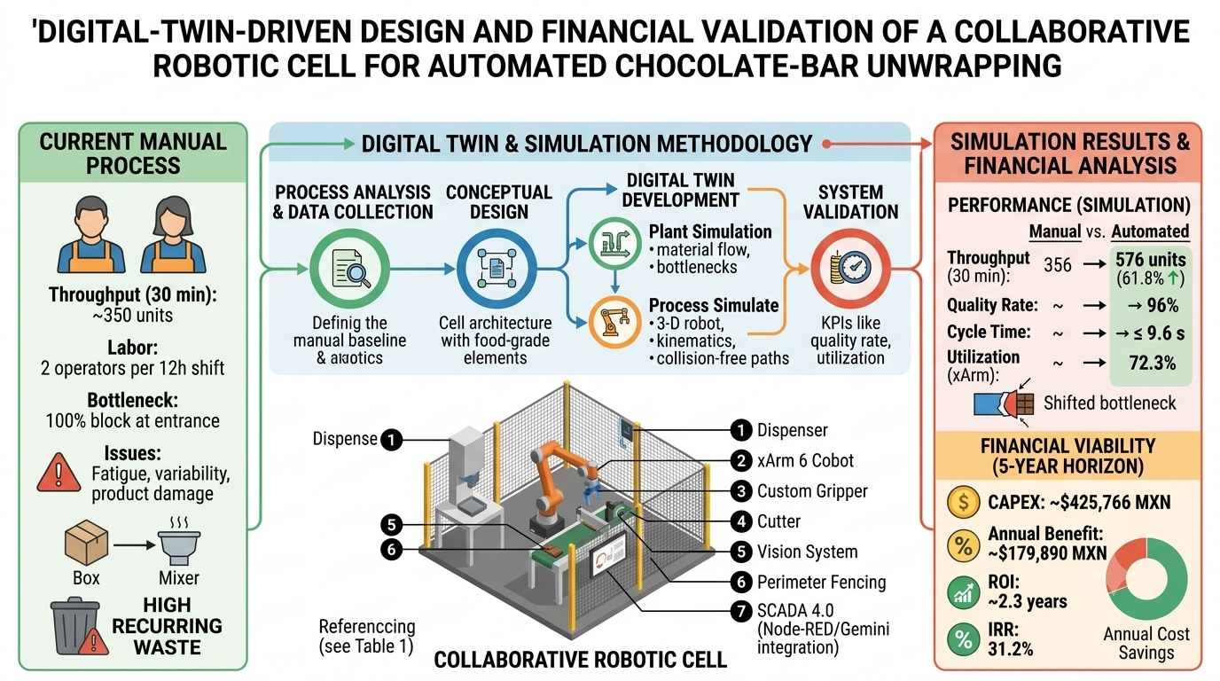
Manual unwrapping of chocolate bars in a family-owned confectionery in Monterrey, Mexico, is a labor-intensive process that produces inconsistent cycle times, high product damage, and elevated payroll costs. This paper presents the design, discrete-event and kinematic simulation, and financial validation of a collaborative robotic cell that automates the gripping, unwrapping, and placement of chocolate bars using a Digital Twin methodology. A macroscopic process model was built in Tecnomatix Plant Simulation to quantify throughput, utilization, and bottlenecks, while a microscopic three-dimensional model was built in Tecnomatix Process Simulate to validate robot reachability, collision-free trajectories, and kinematics for a 6-degree-of-freedom UFACTORY xArm 6 cobot fitted with a custom compliant gripper. A Siemens/Schneider PLC layer, a Node-RED edge gateway, a Firebase database, and a large-language-model-based analytics loop were integrated to provide SCADA 4.0 supervision and closed-loop setpoint correction. Simulation results show that the automated cell increases throughput from 356 to 576 successfully unwrapped units per 30 minutes (a 61.8% improvement) while sustaining a 96% quality rate and eliminates the 100% input-side blockage observed in the manual process. The financial analysis indicates a total capital investment of approximately $425,766 MXN, an annual net benefit of $179,890 MXN, a projected Internal Rate of Return of 31.2%, and a payback period of 2.3 years. These results indicate that a compact, food-grade collaborative robotic cell is a technically feasible and financially attractive solution for small and medium-sized confectionery producers seeking to automate deformable-product handling.
Keywords:
collaborative robotics
; deformable object manipulation
; Digital Twin
; discrete-event simulation
; SCADA 4.0
; food-industry automation
; financial feasibility analysis
1. Introduction
1.1. Project Background and Motivation
The company faces growing demand for products such as its chocolate bar. Unwrapping these chocolates is currently a fully manual operation that creates critical bottlenecks: high labor costs, inconsistent processing times caused by operator fatigue, and recurring waste from damaged products. This paper proposes automating the unwrapping stage with a robotic cell capable of autonomously gripping, unwrapping, and placing the bars on the production conveyor, and reports the roadmap for a system that targets a 96% unwrapping success rate, a reduction of at least 20% in labor cost, and a cycle time at or below 12 seconds per unit, so as to achieve a return on investment within approximately one year.
Industrial automation is a cornerstone of modern manufacturing strategy: replacing repetitive, physically demanding tasks with robotic systems improves performance consistency, reduces operating cost, improves product quality, and increases worker safety. Handling flexible, easily deformable products such as wrapped chocolate bars remains a well-recognized challenge for robotic manipulation, since compliant grippers and adapted motion planning are required to avoid damaging the product while maintaining cycle time [1,2,3]. In the food sector specifically, automation also supports compliance with hygiene standards by reducing the contamination risk inherent to intensive manual handling. For small and medium-sized enterprises (SMEs), the growing accessibility of collaborative robots (cobots) makes it possible to scale production without a proportional increase in the workforce, while simultaneously improving quality metrics.
1.2. Objectives
The main objective of this project is to design, simulate, and validate, using a Digital Twin, a robotic cell capable of autonomously gripping, unwrapping, and placing chocolate bars on the production conveyor, replacing the current manual process. Three SMART (Specific, Measurable, Achievable, Relevant, Time-bound) objectives guide the project.
1.2.1. Objective 1—Product Damage
Reduce the waste of damaged products on the automated unwrapping line to fewer than 10 units per shift, provided the chocolate bars arrive at the station within the manufacturer's temperature specification.
- Specific: reduce damaged units by calibrating gripper pressure, arm speed, and product input conditions.
- Measurable: fewer than 10 damaged units per 12-hour shift, recorded in the daily production log.
- Achievable: through grip-pressure and arm-speed tuning validated during the testing weeks.
- Relevant: directly increases line efficiency and reduces scrapped material and unscheduled downtime.
- Time-bound: achieved by the end of project week 7, verifiable from the first production shift.
1.2.2. Objective 2—Labor Cost
Reduce payroll-related operating expenses by 20% by replacing the manual process with a robotic system, while sustaining a 96% success rate in unwrapping (without damaging the chocolate) during the first year of operation.
- Specific: reduce labor cost in the unwrapping area through robot autonomy.
- Measurable: 20% reduction in payroll expenses and an error rate below 4%.
- Achievable: the robot can work full shifts without fatigue, freeing staff for higher-value tasks (decoration, customer service).
- Relevant: underpins the return-on-investment case for the bakery owners.
- Time-bound: evaluated after the first year of operation.
1.2.3. Objective 3—Throughput
Increase the throughput of the chocolate-unwrapping process by 30% while keeping product damage below 3%, through implementation of the automated handling system, verified by the end of the project validation phase.
- Specific: increase bars unwrapped per hour through optimized conveyor and gripper settings.
- Measurable: 30% increase in hourly throughput with damage below 3%, measured through production reports and quality inspections.
- Achievable: continuous automated operation reduces idle time and variability relative to manual handling.
- Relevant: higher throughput reduces downstream packaging bottlenecks and increases overall manufacturing efficiency.
- Time-bound: verified during the final validation phase, prior to deployment and handoff.
1.3. Scope
The scope is limited to the chocolate-unwrapping line: design of a gripper adapted to the geometry and texture of the chocolate; selection, simulation, programming, and validation of the robotic cell; and the corresponding financial analysis. Physical installation of the cell, modifications to the rest of the production line or the client's processes, adjustments due to packaging-supplier or product-dimension changes, post-approval design changes, and operations outside the designated area are explicitly excluded.
Deliverables include simulations in Process Simulate and Plant Simulation, an integrated-station simulation (robotic arm, sensors, and packaging-waste management), mechanical drawings of the gripper, and this report, comprising research, financial analysis, and validation documentation. Non-negotiable constraints are a 7-week design-assembly-validation window and a budget that guarantees a ROI within a maximum of 12 months. The system must additionally process each bar in 12 seconds or less and comply with sanitary regulations by using food-grade materials and lubricants in any part contacting the chocolate [5]. Stakeholders range from company production management (sponsors ensuring ROI) to technical advisors, food-safety operators and supervisors, and plant maintenance technicians. Key risks that must be mitigated include the physical deformability of the chocolate, the risk of missing the required cycle time, the slipperiness of the wrapping material, and variability in the product's arrival temperature.
2. Current Process and Assumptions
2.1. Description of the Chocolate Process
The company currently operates two 12-hour shifts, each staffed by two employees who spend up to one hour unwrapping chocolates. These two workers unwrap approximately 350 bars in 30 minutes (about 700 per hour), all destined for the chocolate coating used. The process is entirely manual and prone to fatigue-driven bottlenecks, resulting in losses recurring and motivating the automated system proposed in this paper.
Figure 1.
Baseline manual process, modeled in Plant Simulation.
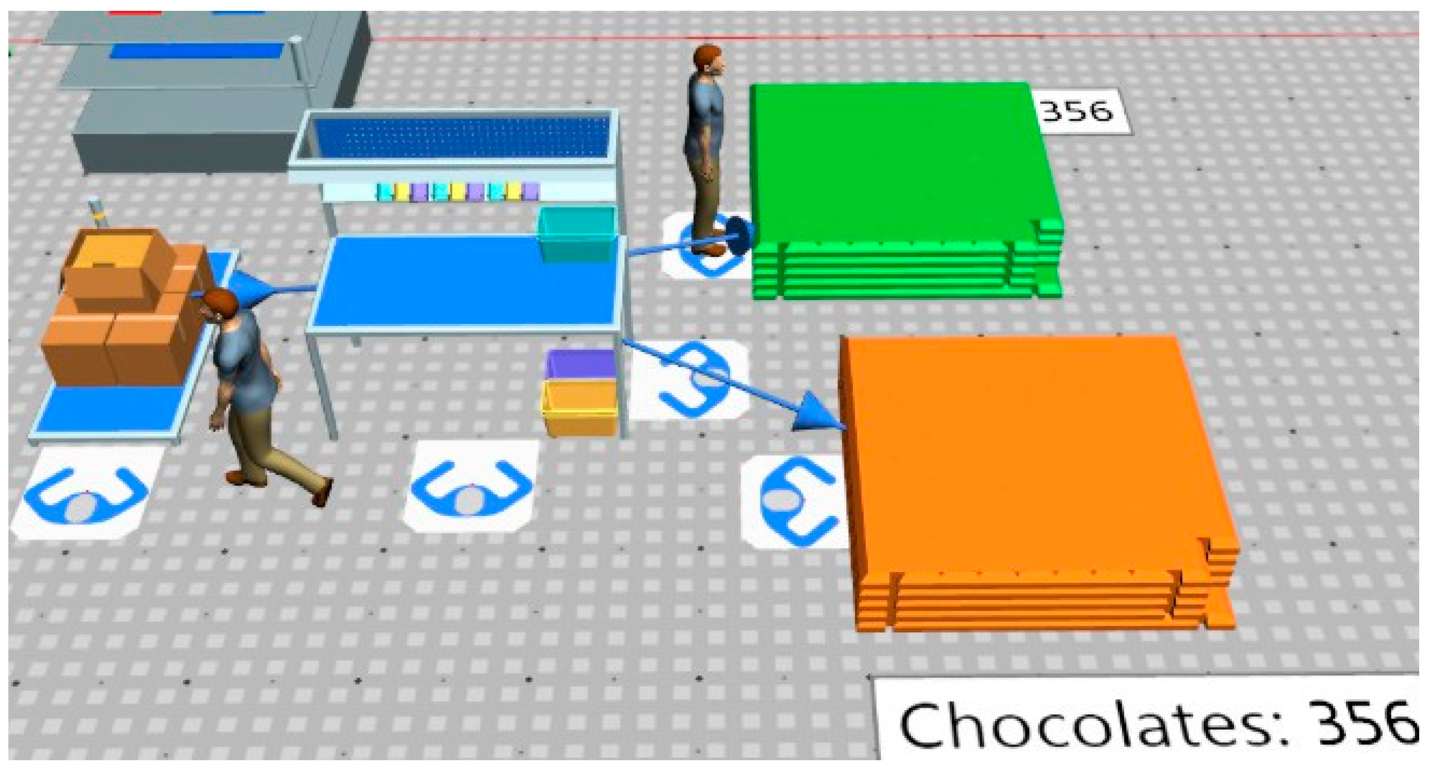
The process begins with two operators opening a large box containing 32 small packages of 6 chocolates each (192 chocolates per large package). Operators remove the wrapper from each chocolate at an estimated cycle time of 12 seconds per unit. After unwrapping 360 chocolates (17 kg), the bars are transported directly to the mixer, which requires 6 hours to complete its cycle.
2.2. Assumptions
The following assumptions were adopted for the automated system to operate optimally:
- Controlled temperature: chocolate bars arrive at the cell within 26–29°C, ensuring sufficient rigidity for robotic handling.
- Product specifications: bar dimensions, weight, and packaging characteristics remain consistent throughout production.
- Operator training: operators are adequately trained to supervise, operate, and perform basic troubleshooting of the cell.
- Utilities: electrical power and network communication are continuously available.
- Hardware: the cobot, sensors, conveyors, and PLC perform according to manufacturer specifications.
- Maintenance: preventive maintenance is performed on the recommended schedule.
- Simulation fidelity: the Process Simulate and Plant Simulation models accurately represent the real production-line environment.
3. Methodology
3.1. Digital Twin Development Approach
The project followed a Digital Twin methodology to design, simulate, validate, and evaluate the automated cell, structured in four phases.
- Process analysis and data collection: the manual process was characterized in terms of production rate, cycle time, product-handling conditions, and bottlenecks, establishing the baseline for comparison.
- Conceptual design of the automated cell: cell architecture (conveyors, sensors, cutting station, robotic manipulator, vision system, safety devices, PLC) was defined considering food-industry requirements, safety standards, and economic viability.
- Digital Twin development: Plant Simulation modeled overall production flow, throughput, bottlenecks, and resource utilization; Process Simulate modeled the robotic workstation in 3-D, validating reachability, trajectories, collision avoidance, and kinematics. CAD models built in SolidWorks were imported into Process Simulate and converted into resources with programmable joints and motion.
- System validation and performance analysis: throughput, cycle time, utilization, product quality, and labor requirements were evaluated against the SMART objectives across multiple simulation runs.
3.2. Software Tools
- SolidWorks: mechanical design of structural elements and the chocolate-bar gripper.
- Tecnomatix Plant Simulation: discrete-event model of the production line for material-flow analysis, statistics, and identification of inefficiencies.
- Tecnomatix Process Simulate: robotic operation tree, path editor, and sequence editor, used to prevent 3-D collisions and validate motion.
3.3. CAD Model and Layout
The proposed process layout, designed in SolidWorks, is shown in Figure 2.
4. Discrete-Event Simulation of the Production Line
4.1. Model Architecture
The Tecnomatix Plant Simulation model provides a macroscopic, event-driven representation of the production line, evaluating plant capacity, material-flow logistics, and bottlenecks at critical stations, including the waste pick-and-place process, the chocolate dispenser, and the wrapper-cutting station. Mapping the system digitally allowed cycle times, work shifts, and storage capacities to be entered so that high-demand scenarios could be tested and productivity optimized before any physical investment.
4.2. Process Flow
Figure 3.
Process flow of the proposed automated system.
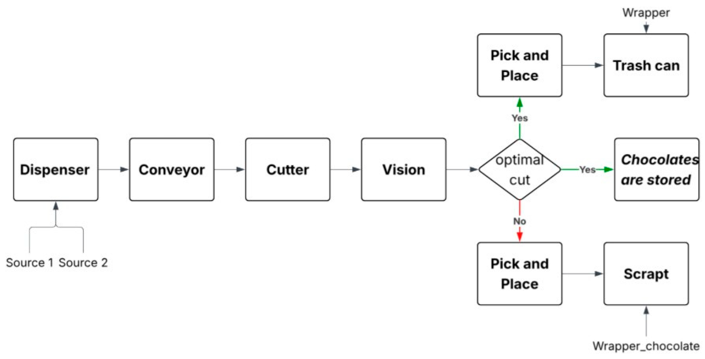
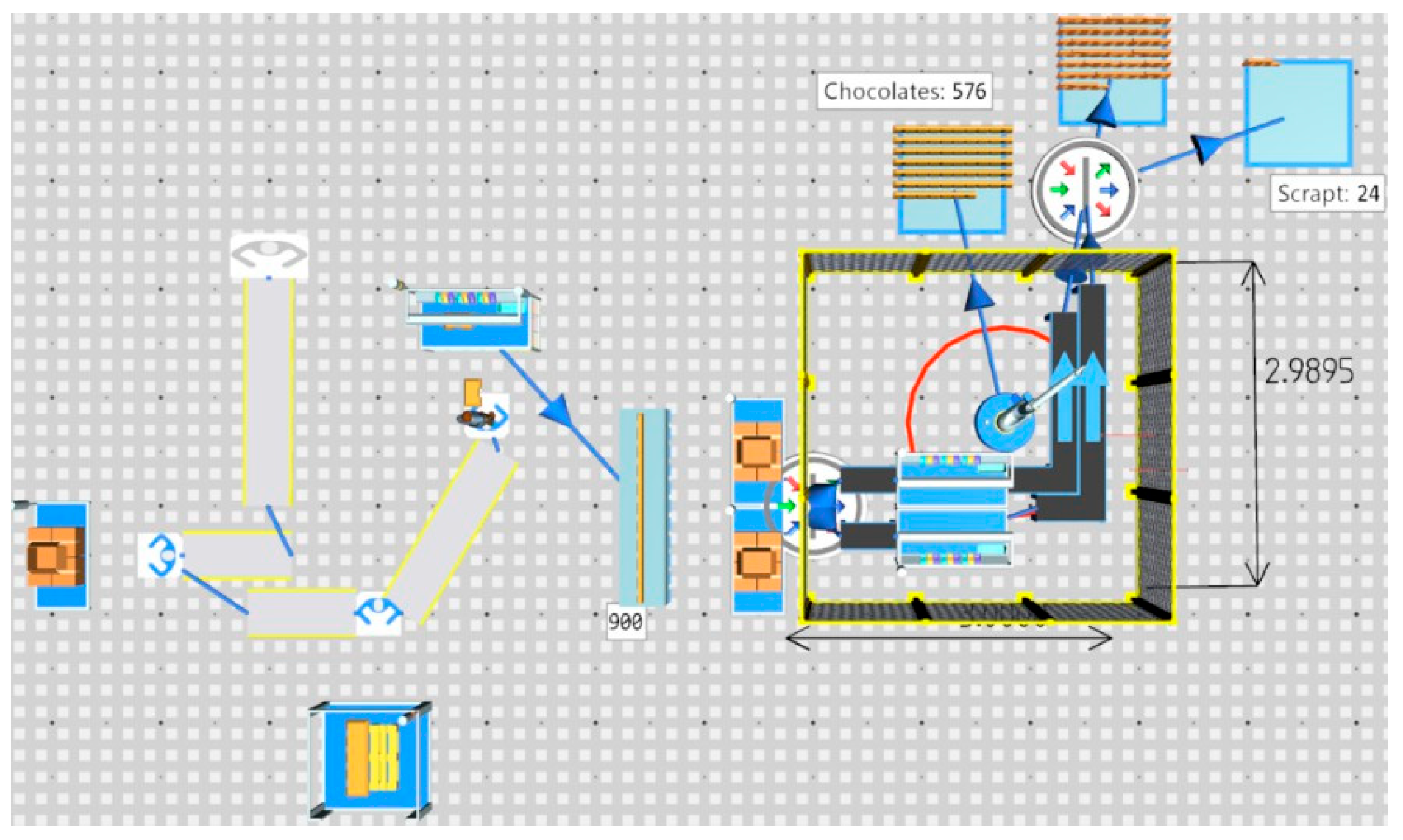
Figure 4.
Plant Simulation model of the automated cell.
4.3. Resources
One operator per shift is dedicated to opening the large chocolate box and loading 192 wrapped chocolates into the dispenser; a robot performs the pick-and-place operation. Although company runs two 12-hour shifts, the simulation was executed over a representative 30-minute window with the following elements:
- Three sources
- Two conveyors
- One operator
- Three dismantling stations
- One pick-and-place station
- Four storage bins (chocolates, wrappers, scrap, wrapped chocolates)
- One buffer
- One drain
4.4. Key Performance Indicators
4.4.1. Pieces Processed in 30 Minutes
Figure 5.
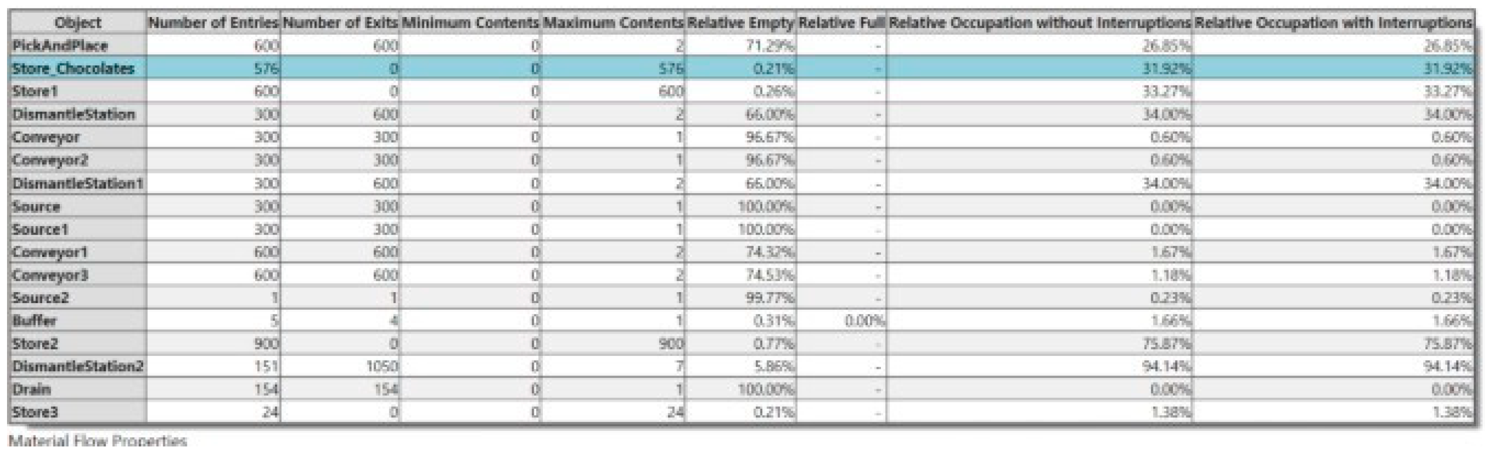
Material-flow properties for the automated cell.
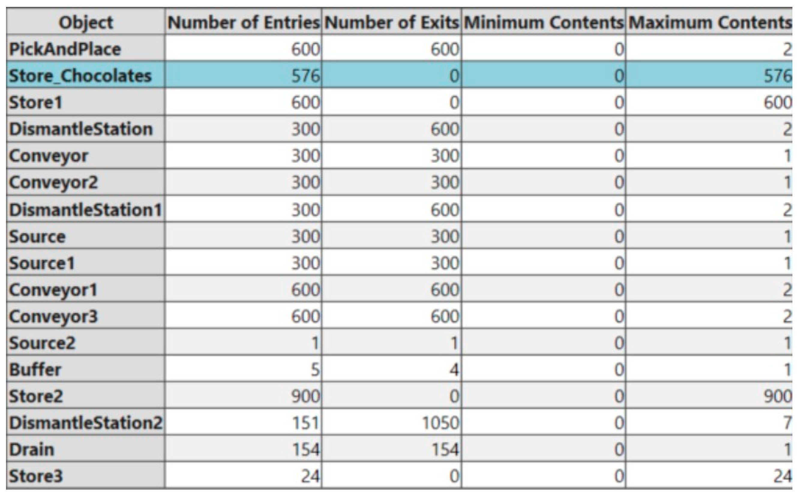
Of the 600 chocolates processed in 30 minutes, 576 passed quality control and were routed directly to the container, corresponding to a 96% quality rate across all processed units.
4.4.2. Worker Employment Rate
Figure 6.
Percentage of work time actively employed by the supervising operator.

During the 30-minute simulation window, an operator supervising the chocolate-opening process is actively engaged only 20% of the time, leaving capacity for the worker to perform other tasks during the shift.
4.4.3. Relative Empty (Utilization)
Figure 7.
Relatively empty percentage by station.
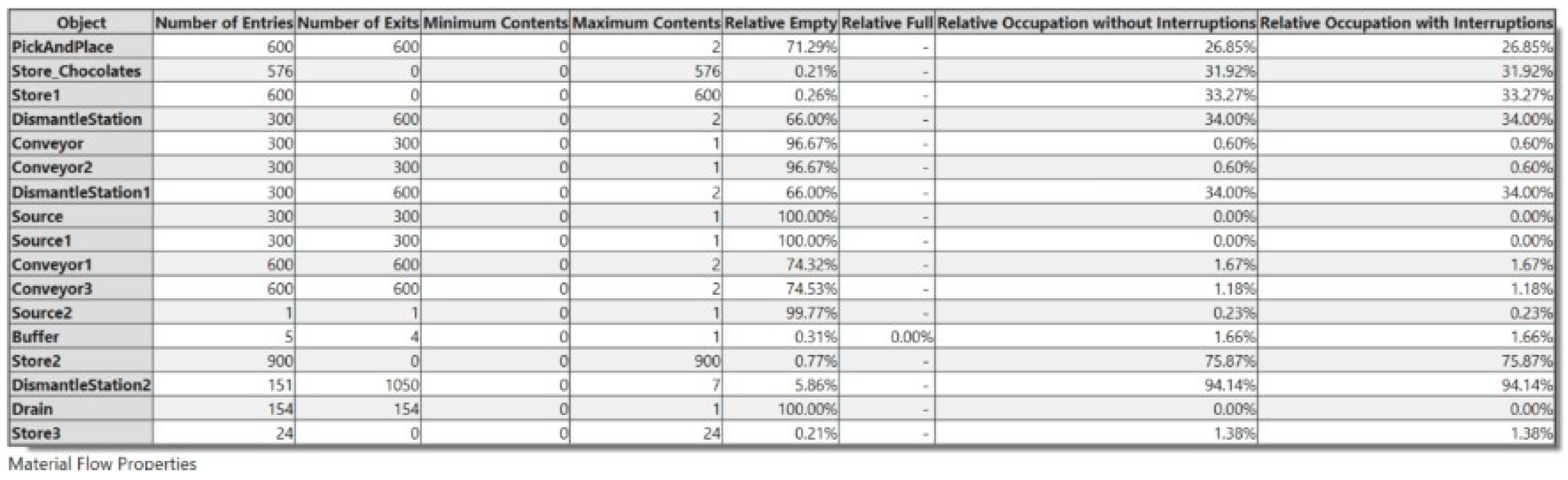
This metric reflects the utilization reached by a given station or resource. The pick-and-place station reached a utilization rate of 71.29%, while the dismantling stations (0 and 1) reached a maximum fill rate of 66.6%, indicating that neither of these critical points had yet reached a level that would trigger a bottleneck.
5. Robotic Cell Design and Kinematic Validation
The Tecnomatix Process Simulate model focused on detailed three-dimensional and kinematic analysis at the workstation scale. Geometries and layouts modeled in SolidWorks were imported and converted into smart components with programmable joints and motion, enabling validation of sequences of operations (SOPs), optimization of actuator paths, collision prevention in three-dimensional space, and operator-ergonomics analysis.
5.1. Station Layout
The cell uses a linear input-output layout to minimize floor space and was designed in accordance with international robot-safety standards, including ANSI/RIA R15.06-2012 (the U.S. national adoption of ISO 10218), ISO 14120, ISO 13857, ISO 13855, and ISO 10218 Parts 1 and 2 [6].
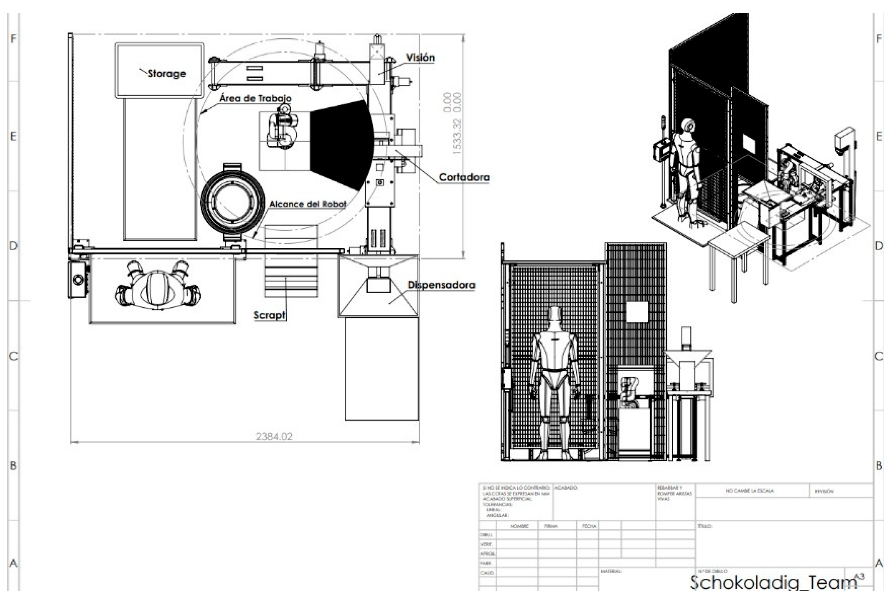
Figure 8.
Station layout and dimensions.
5.2. Key Elements of the Layout
- Infeed conveyor zone: receives wrapped bars from the dispenser and includes a spacing mechanism for uniform bar spacing prior to detection.
- Cutter zone: cuts the ends of both chocolate bars at a 40° angle to minimize waste.
- Detection and stop station: photoelectric sensors identify bar presence and orientation; a pneumatic stop pin holds the bar in place.
- Robot work area: the robot base is mounted on a fixed pedestal, centrally positioned relative to the inlet stop station and outlet conveyor, leaving clearance for full gripper extension.
- Vision system: a camera opposite the robotic arm detects chocolates that are not in optimal condition to continue the process.
- Wrapper-waste collection: a ramp next to the entry station directs detached wrappers to a sealed floor-level container outside the robot's work envelope.
- Safety perimeter: light curtains on operator-access sides and physical guarding around the remaining perimeter define the safety zone.
5.3. Equipment and Resources
Table 1 summarizes the elements specified for the automated system.
5.4. Master–Slave Communication Protocol
The Siemens S7-1200 acts as the master controller, using fast solid-state outputs to trigger the cutter and vision systems. Connected over a local Ethernet star topology, it communicates with UFACTORY xArm 6 (slave). The PLC sends trajectory commands directly to the robot over native Modbus TCP through a single shielded industrial cable, reducing wiring complexity and integration cost.
5.5. Operations
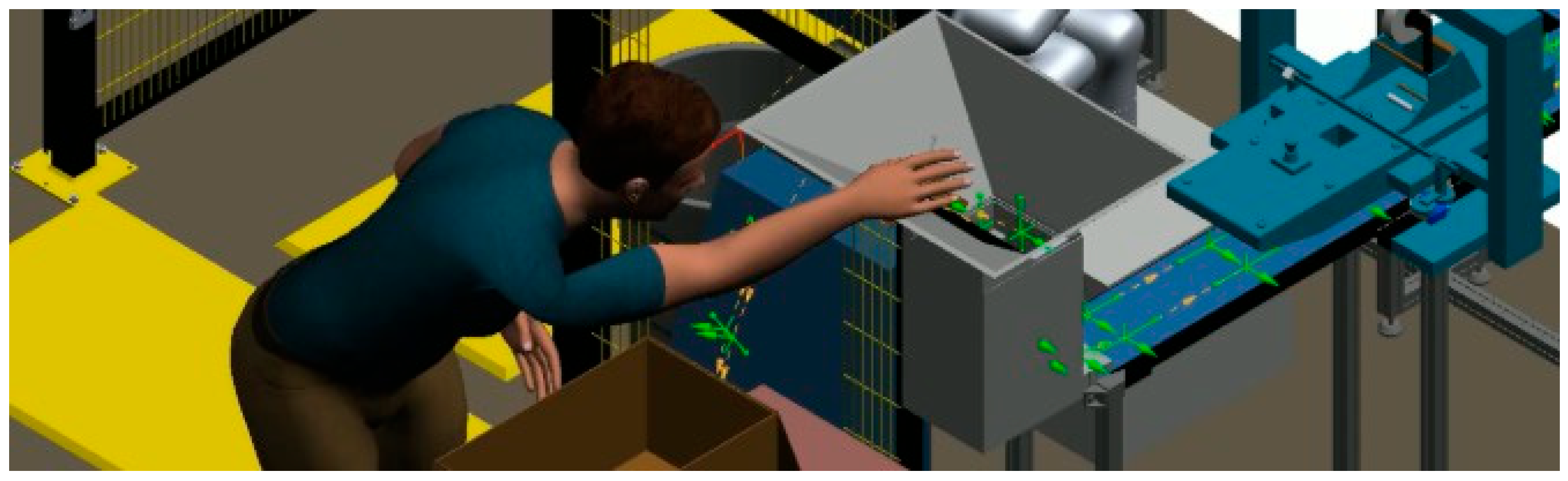
The simulation uses Process Simulate's operation tree, path editor, and sequence editor. The operator places chocolate bars from the large box into the dispenser; the bars fall and are arranged in parallel; they advance to the cutting zone, pause briefly, and continue to the inspection zone; bars that pass inspection have their wrappers removed by the pick-and-place robot and deposited in the waste container, while bars that fail inspection are placed in the scrap bin by the same robot. The path editor added motion and kinematics to individual parts; the operation tree organized the created paths; and the sequence editor determined movement timing, functioning much like a video-editing timeline.
Figure 9.
Automated system implemented in Process Simulate.
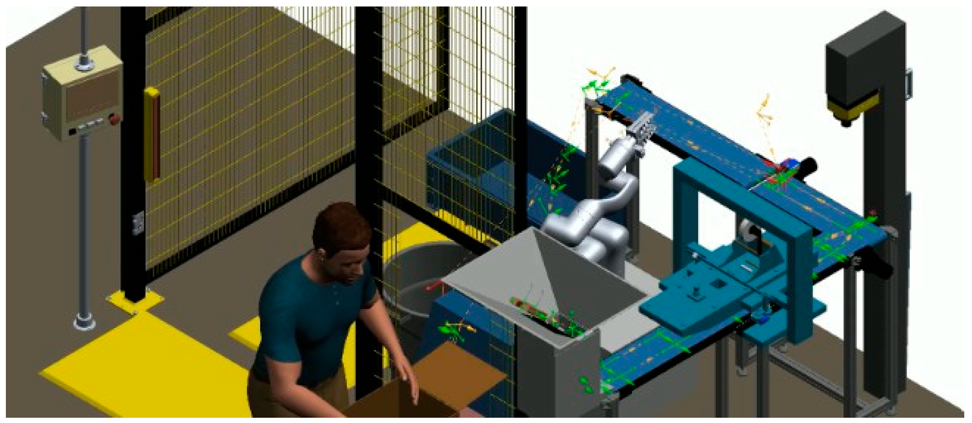
Figure 10.
Operator interacting with the dispenser in Process Simulate.
5.6. Motion Validation
Motion validation and collision avoidance between components (robot, chocolates, conveyors, and human operator) were verified through recorded simulation videos, provided in the project appendix.
5.7. Kinematic Design
Within Process Simulate, imported components are classified as parts or resources. The UFACTORY xArm 6, the cell's primary robot-type resource, required a full 6-degree-of-freedom kinematic chain, with each link and joint entered explicitly. Chocolates were imported as parts, so only trajectories (not kinematics) needed to be defined. The soft gripper, a revolute mechanism with 4 fingers, required 4 joints connected to a common base.
6. SCADA, HMI, and AI Integration (SCADA 4.0)
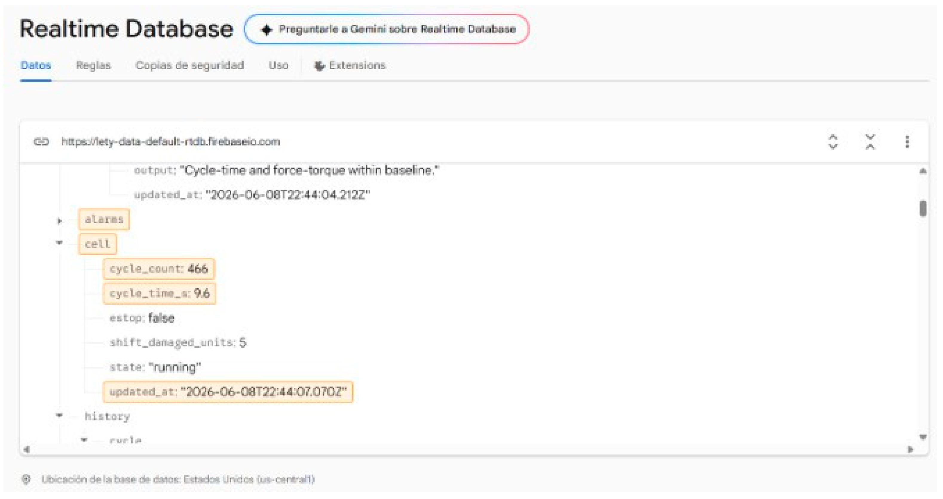
The supervisory database is organized under a single root node (“lety”), divided into the process stages of the cell infeed, cutting, inspection, unwrapping, and dispatch each storing live signals such as conveyor speed, cut count, vision result, gripper force, force-torque, and bin level. Additional nodes hold plant metadata and team information, the SMART targets expressed as data, an input–output map linking every signal to a PLC address and protocol, a key-performance-indicator block, a grouped alarm list, AI outputs for the five SCADA 4.0 pillars, and a short time-series history for charting. A separate rules file enforces data types and value ranges for every field and constrains alarm severity and cell mode to fixed sets. For demonstration purposes, read and write permissions were left open, with the recommendation to add authentication before any real deployment.
Figure 11.
Firebase real-time database structure.
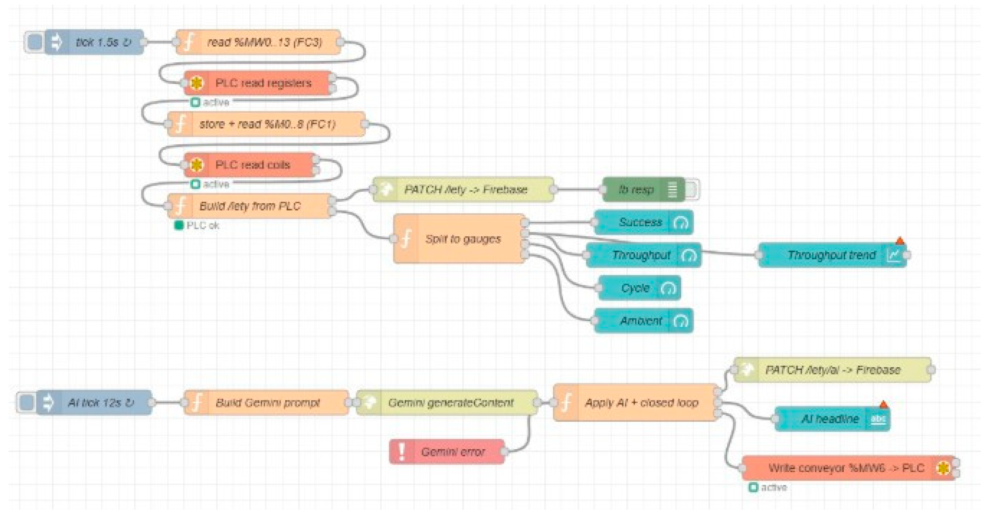
Node-RED serves as the edge gateway. A timed trigger polls the controller every 1.5 seconds, a function node assembles the “lety” object, and an HTTP request writes it to Firebase. A second branch, running every 12 seconds, sends the current data and the five SCADA-4.0-pillar prompts to a large language model, parses the structured response, writes the results to the AI node, and returns the recommended conveyor setpoint to the controller. A catch node routes any model failure to a local rule engine so that analysis never stops. The same flow exposes an optional Node-RED dashboard with gauges and a trend chart; two flow variants were produced one simulating the cell for a standalone demonstration, and one reading the real controller over Modbus TCP.
Figure 12.
Node-RED edge-gateway structure.
The controller is a Schneider Modicon M221 (model TM221ME16R/G) with an embedded Ethernet port and Modbus TCP server. A ladder program, written in EcoStruxure Machine Expert Basic, loads representative values into memory words %MW0–%MW13 and status bits %M0–%M8 following the register map agreed with Node-RED; the conveyor word is left for Node-RED to write, demonstrating the closed loop. The program was downloaded to the built-in simulator, the Modbus TCP server enabled, and the controller placed in run mode; Node-RED reads memory words and bits using Modbus function codes 3 and 1 and writes the conveyor setpoint with function code 6.
Figure 13.
PLC configuration.
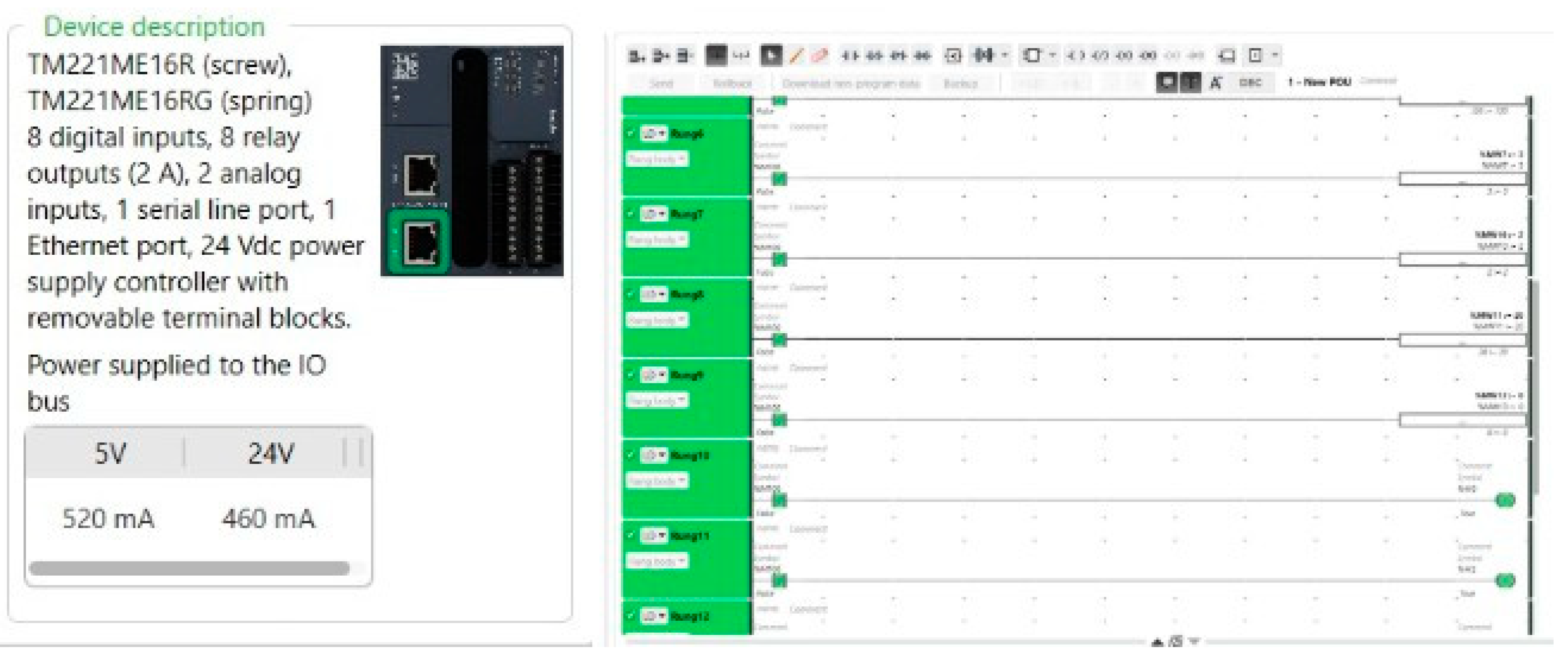

Table 2.
PLC memory addresses are mapped to Node-RED.
| Address | Description |
|---|---|
| %MW0 | Unwrap success rate (×10) |
| %MW1 | Cycle time in seconds (×10) |
| %MW2 | Throughput per 30 minutes |
| %MW3 | Ambient temperature (×10) |
| %MW4 | Force torque (×10) |
| %MW5 | Gripper force (×10) |
| %MW6 | Conveyor speed percent (written by Node-RED) |
| %MW7 | Damaged units per shift |
| %MW8 | Cut count |
| %MW9 | Unwrapped output count |
| %MW10 | Rejected count |
| %MW11 | Bin level percent |
| %MW12 | Cycle count |
| %MW13 | Robot error code |
| %M0 | Running |
| %M1 | Emergency stop |
| %M2 | Light curtain OK |
| %M3 | Force-torque alarm |
| %M4 | Bar present |
| %M5 | Cutter extended |
| %M6 | Seal break OK |
| %M7 | Chocolate temperature OK |
| %M8 | Vision pass |
The model was tuned in several steps to meet the project targets and make self-correction visible. Ambient temperature was given mean-reverting behavior averaging 21–26°C, with 28°C treated as an extreme condition; cycle time was held at or below 10 seconds, so throughput reaches the 360-units-per-30-minutes target, displayed between 360 and 375. Reject probability and force-torque thresholds were lowered so damaged units remain well below the 10-per-shift limit. Once threshold values were matched to realistic operating ranges, the alarms responded immediately when a value moved out of range, and the AI loop corrected setpoints before the deviation grew.
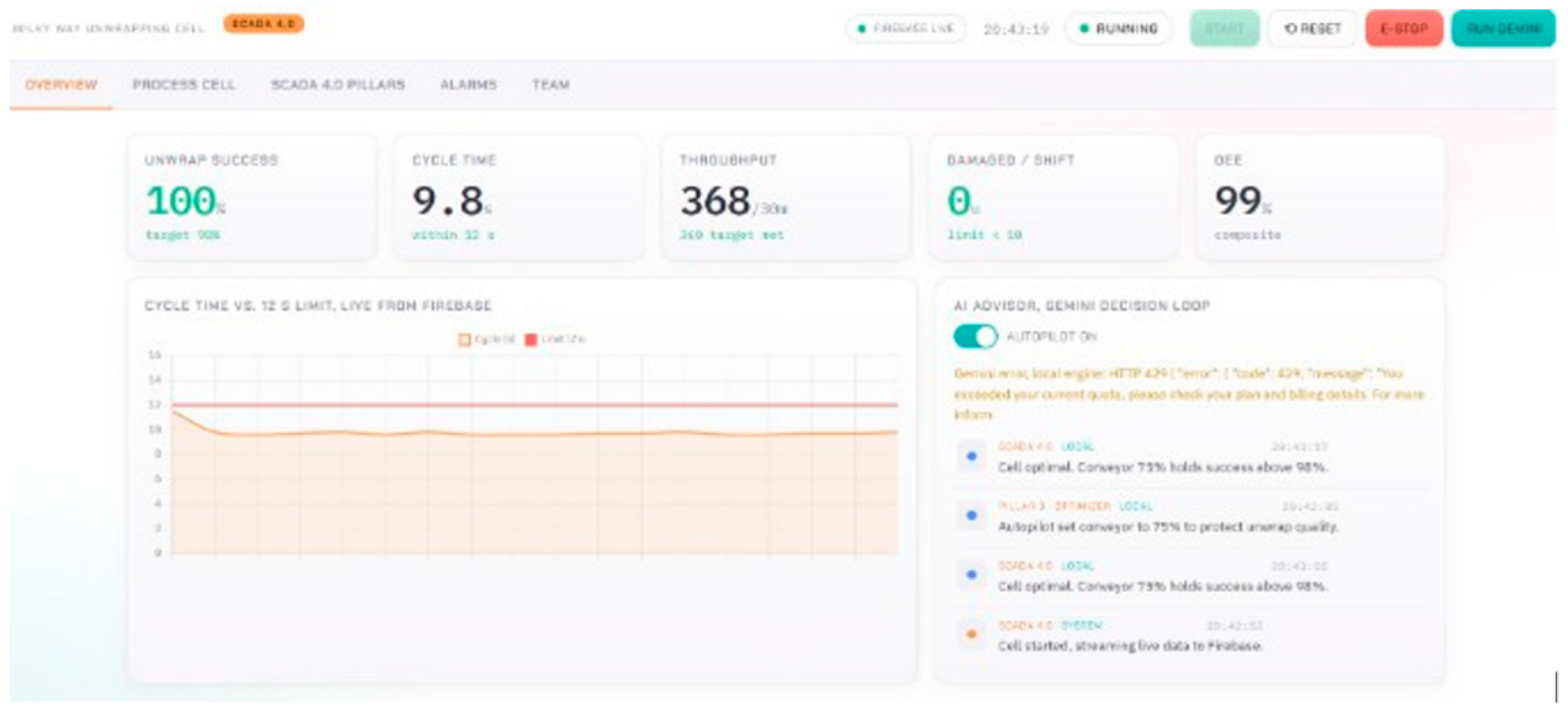
The supervisory dashboard is a single HTML file connected directly to Firebase that updates automatically whenever the data changes. It presents an overview with key-performance-indicator cards, a process-cell view showing the five stages in sequence with live values and an embedded video per stage, a panel for the five SCADA 4.0 pillars with the AI output, an alarm console that groups repeated events by root cause, and a team-and-roadmap section. The live dashboard is available at: https://a01659574.github.io/Milkyway-project/lety-scada-final.html
Figure 14.
Data-supervision dashboard interface.
7. Results and Analysis
The experimentation and analysis phase in Tecnomatix Process Simulate and Plant Simulation allowed quantitative validation of the operational efficiency of the robotic cell.
7.1. Throughput
A comparative analysis of both simulations over a 30-minute period reveals a significant performance increase. The current manual process unwraps 356 chocolates. The proposed automated cell processes 600 units and, operating at a 96% quality-effectiveness rate, yields 576 successfully unwrapped chocolates a 61.8% improvement over the previous process.
Figure 15.
Baseline (manual) performance.

Figure 16.
Performance of the cell to be implemented.
7.2. Bottlenecks
Constraint analysis reveals a radical transformation in bottleneck location between models. In the original model, the main bottleneck was located at the system entrance, where raw material remained blocked 100% of the time because downstream stations could not absorb the flow and manual transport was the limiting factor. After implementing the automated cell, this initial blockage was completely eliminated, allowing the sources to operate unobstructed or in standby 100% of the time.
Figure 17.
Bottlenecks in the current process.

Figure 18.
Bottleneck location in the implemented cell.
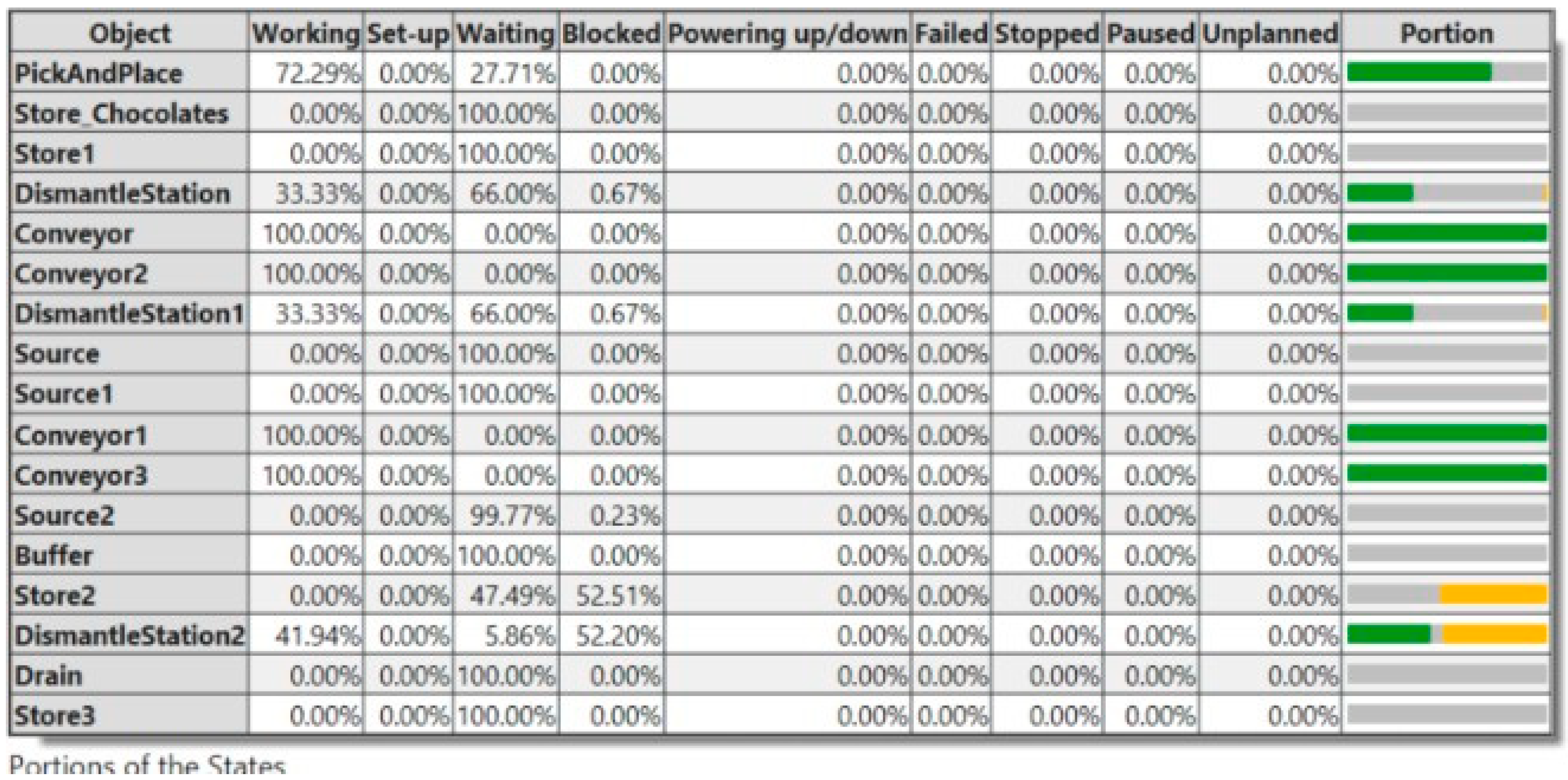
However, accelerating the continuous flow shifted the constraint to the final section of the line: in the automated-cell simulation, the cutting station registered a 52.20% blockage rate, indicating a new bottleneck caused by saturation during cutting or by the evacuation rate to the exit area.
7.3. Utilization
In its current state, manual bar-opening shows a productive utilization rate of only 7.42%, with 15.08% of time blocked and 77.50% in an unproductive waiting state. In the automated model, load was balanced so that the cutting zone reached an effective working time of 33.33% while blockages fell to a minimum of 0.67%. The pick-and-place robotic arm became the most utilized component in the automated plant, achieving 72.29% active utilization and limiting standby time to 27.71%.
7.4. Cycle Times
Evaluation of cycle times and material dwell times explains the logistical lag of the current process relative to the proposed cell. In the manual scenario, the WorkerPool spent 30.61% of its time transporting materials and another 30.67% moving to workstations more than 60% of the work cycle invested in transfer activities that added no direct value. Replacing this human logistics chain with a continuous conveyor circuit standardized and significantly reduced transfer and communication times, accelerating the processing cycle and enabling a faster continuous-flow response.
8. Financial Analysis
Although company was reserved with its financial data, a financial feasibility analysis was developed from the estimates obtained during the project.
Figure 19.
Descriptive cost table.
8.1. Criteria Considered
- Operator cost: based on the general-zone minimum daily wage published for Mexico by CONASAMI (approximately $248.93 MXN/day base, general zone) [7]. Factoring in the mandatory minimum benefits required by law (IMSS, INFONAVIT, Christmas bonus, paid vacation), the real integrated monthly cost is approximately $11,500 MXN, or approximately $138,000 MXN annually.
8.2. Cost Estimates
- UFACTORY xArm 6 robot: official market list price of $9,500.00 USD for the 6-axis cobot; it does not require a separate external controller, as one is included from the factory.
- Montech TB30D24 conveyor: a high-precision polyurethane-belt system from the TB30 series, averaging $1,450.00 USD per unit.
- Electric/pneumatic gripper for the cobot: estimated at $1,200.00 USD, suitable for end-of-arm integration on the xArm 6.
- Automated sealer/cutter: $1,500.00 USD, a cutting station adaptable to the sensor-driven automation environment.
- HMI (touchscreen control panel): $650.00 USD for a compact panel compatible with the cobot's architecture.
- Dispenser: $800.00 USD for the process dosing unit.
- Andon light tower: a standard three-level industrial light tower (green = normal operation, yellow = batch change/warning, red = downtime due to fault or safety activation), estimated at $120.00 USD.
- Cell energy and maintenance: the annual amount stipulated in the cost list is $7,892.00 USD.
8.3. Total Investment
Total capital expenditure (CAPEX), summing all hardware, is $24,469.31 USD. This covers the physical purchase of hardware, safety sensors, perimeter fencing, and peripherals for the collaborative cell, and excludes recurring operational costs such as salaries or maintenance. Converting at 17.540 MXN/USD yields a total investment of $425,765.994 MXN.
8.4. Annual Net Benefit, ROI, and IRR
The annual benefit is computed as
where Bannual is the annual benefit, CLabor,prev is the previous labor cost, CLabor,new is the new labor cost, M is maintenance, and P is power consumption.
Bannual = (CLabor,prev) − (CLabor,new + M + P)
Current situation (manual): two operators work 12-hour shifts. Because this exceeds the legal 8-hour workday, the Federal Labor Law mandates overtime pay, raising the real integrated cost (including IMSS and INFONAVIT) to an estimated $19,500 MXN monthly per operator [7].
CLabor,prev = 19,500 MXN × 2 operators × 12 months = 468,000 MXN/year
New situation (automated): a single operator on a regular 8-hour shift, at an estimated monthly cost of $12,500 MXN.
CLabor,new = 12,500 MXN × 12 months = 150,000 MXN/year
Substituting the labor costs and the $38,110 MXN/year combined maintenance-and-power cost (M + P) into Equation (1):
Bannual = 468,000 − (150,000 + 138,110) = 179,890 MXN/year
8.5. Return on Investment
ROI = [Invinitial (CAPEX) / Bannual] × 12 months = (425,765.994 / 179,890) × 12 ≈ 2.3 years
The resulting payback period of approximately 2.3 years exceeds the 12-month target set by the partner organization but is considered realistic: it reflects the inclusion of perimeter safety fencing to protect operators, high-precision hardware, and a machine-vision quality-inspection system based on trained pattern-recognition image algorithms that determines whether each chocolate bar is fit to continue down the line and signals the cobot accordingly.
8.6. Internal Rate of Return
The Internal Rate of Return (IRR) evaluates the project's profitability over a 5-year horizon, representing the compounded annual interest rate of the invested capital i.e., how the project compares to depositing the same capital in a fund or bank account. The IRR is the discount rate r that satisfies:
−CAPEX + Σt=15 [Bannual / (1 + r)t] = 0
Substituting the known annual benefit of $179,890 MXN and the $425,765.994 MXN initial investment, and solving iteratively:
| Year | Discounted cash flow (MXN, r = 31.2%) |
| 1 | 137,090 |
| 2 | 104,473 |
| 3 | 79,617 |
| 4 | 60,674 |
| 5 | 46,238 |
Summing the five discounted cash flows yield approximately $428,092 MXN, which offsets the $425,765.994 MXN initial investment (−425,765.994 + 428,092 ≈ 0) when r = 31.2%, confirming the IRR by iterative numerical solution. An IRR of 31.2% comfortably exceeds the 15–20% threshold typically used as a benchmark for an attractive industrial investment.
9. Improvement Proposals
9.1. Alternative Scenarios
One improvement opportunity concerns the inclination at which chocolates are dispensed on the conveyor: tilting the bar so the chocolate is weighed more to one side inside the wrapper would improve cutting effectiveness and reduce waste during the cutting step.
A second opportunity concerns robot trajectory optimization: refining the timing and angles followed through the robot's path in Process Simulate can further reduce cycle time, increasing the quantity of chocolates processed in 30 minutes and moving output closer to target [2].
9.2. Justification
Automating the unwrapping process is justified by the pressing need to mitigate the inefficiencies of manual work, which produces high operating costs, human-fatigue-driven inconsistency, and constant product-damage losses. Baseline analysis showed the dismantling station operating at only 7.42% productive utilization a direct consequence of personnel losing more than 60% of their workday to logistical transfers that add no value, causing a 100% blockage at the system's input. The collaborative robotic cell eliminates this constraint entirely, increasing processing from 356 to 600 units every 30 minutes. From an economic and technological perspective, the project is supported by an IRR of 31.2%, comfortably exceeding industrial viability thresholds, and by the integration of a Digital Twin and SCADA 4.0 architecture that ensures a robust, secure solution aligned with international food-industry standards [6].
10. Conclusions
The development, modeling, and validation of the automated robotic cell using a Digital Twin methodology proved to be a technically feasible and effective solution for overcoming the production limitations.
Simulation results confirm that automating the unpacking process increases throughput by 61.8%, from 356 to 576 chocolates successfully processed and unpacked per 30 minutes of operation, while maintaining a 96% quality and effectiveness rate fulfilling the primary objective of minimizing waste and structural product damage.
System-constraint analysis confirms that the transition to continuous flow, supported by conveyor belts and the UFACTORY xArm 6 robotic arm, eliminates the 100% input-side blockage present in the original manual model.
From an economic standpoint, the project reduces recurring payroll expenses, decreasing reliance on multiple operators working extended 12-hour shifts. Although the calculated ROI of 2.3 years exceeds the initial 12-month target, this extended payback period is justified by the inclusion of high-precision hardware, an integrated machine-vision system, and perimeter-fencing components that guarantee personnel safety.
Finally, an IRR of 31.2% and an annual net profit of $179,890 MXN confirm the financial soundness of the proposal, positioning robotic automation together with real-time SCADA 4.0 monitoring as pillars for the company's sustained growth.
Acknowledgments
The authors thank the course faculty of Automation of Manufacturing Systems at Tecnológico de Monterrey, Campus Monterrey: Alejandra Molina-Leal, Antonio Carlos Bento, José Abraham Valdivia-Puga, Oliverio Hernández-Argumedo, Raquel Tejeda-Alejandre, Rubén Febronio García-Martínez - for their guidance throughout the project.
Appendix A
Supplementary material, including simulation videos and additional CAD/PLC files, is available at the project repository: https://drive.google.com/drive/folders/138a1ZMUt45MFr1mLr0UMDVTWMJhiQ4Mz.
References
- Bimbo, J.; Liarokapis, M.; Malvezzi, M.; Salvietti, G. Editorial: Robotic grasping and manipulation of deformable objects. Front. Robot. AI 2023, 9, 1108038. [Google Scholar] [CrossRef]
- Makris, S.; Kampourakis, E.; Andronas, D. On deformable object handling: Model-based motion planning for human–robot co-manipulation. Computers & Electrical Engineering 2022. [Google Scholar] [CrossRef]
- Han, L.; Wang, H. Robotic manipulation of deformable objects: A comprehensive review. Robot. Intell. Autom. 2026, 46(2), 1–16. [Google Scholar] [CrossRef]
- Chen, L. (2025). Learning to open deformable bags with a bimanual robot (Technical Report No. UCB/EECS-2025-111). University of California, Berkeley, EECS Department.
- U.S. Food and Drug Administration. Food and Drug Administration. (2024). Code of Federal Regulations Title 21, §177.2600: Rubber articles intended for repeated use. U.S. Department of Health and Human Services. U.S. Department of Health and Human Services. Available online: https://www.ecfr.gov/current/title-21/chapter-I/subchapter-B/part-177/section-177.2600.
- International Organization for Standardization. (2025). ISO 10218-1:2025 and ISO 10218-2:2025 — Robotics: Safety requirements for industrial robots and robot system integration. ISO; also adopted in the United States as ANSI/RIA R15.06.
- Comisión Nacional de los Salarios Mínimos (CONASAMI). (2025). Resolución del H. Consejo de Representantes de la CONASAMI, que fija los salarios mínimos generales y profesionales, Diario Oficial de la Federación, effective January 1, 2026.
Figure 2.
CAD model and layout of the proposed automated cell.
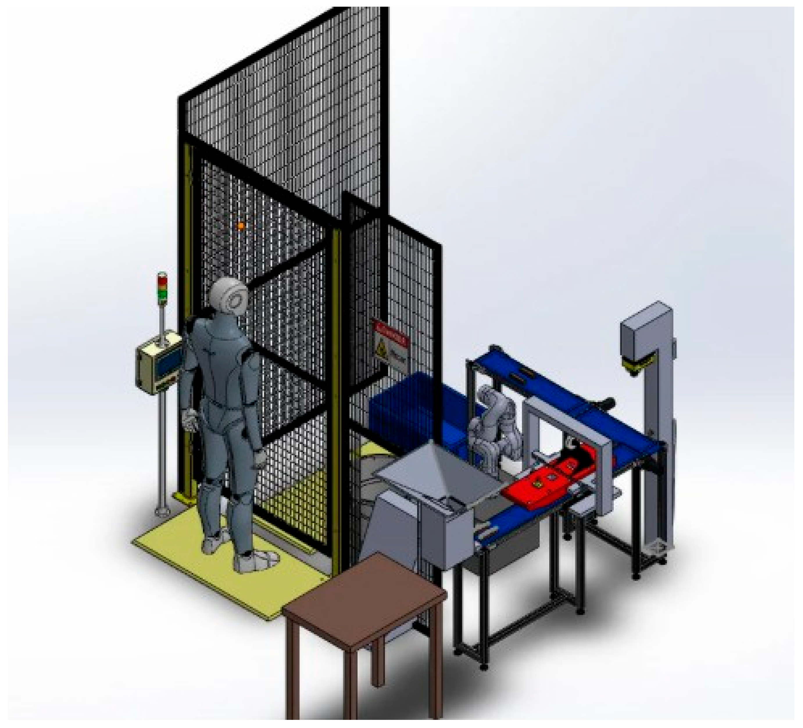
Table 1.
Elements of the automated system.
| Element | Function / Justification |
|---|---|
| UFACTORY xArm 6 (6-DOF cobot) | Programmable trajectories, high precision, IP65-rated for food-industry environments; uses the xArm BIO ecosystem for tool-changer compatibility with grippers from multiple manufacturers. |
| Custom flexible gripper | Four compliant fingers with adjustable servo pressure secure the deformable chocolate bar without surface damage, complying with FDA food-contact rules [5]; connects to the cobot through the BIO ecosystem. |
| Cutter | Fast, repetitive cutting action with simple maintenance and reliable industrial operation. |
| Dispenser | Arranges wrapped bars in parallel for a uniform feed rate, eliminating manual positioning. |
| Vision trigger system | Chocolate absorbs normal white light; targeted red/blue spectra with a monochrome camera maximizes optical contrast, enabling reliable detection of cracks, burrs, or millimeter-scale defects. |
| Temperature sensor | Verifies, without contact, that the chocolate is within the ideal 26–29°C range before robotic handling. |
| Photoelectric sensor | Synchronizes the system with the robot to detect the bar and trigger unwrapping. |
| Barrier / safety-mat sensors | Ensure operator’s safety when entering the cell; a pressure-sensitive mat signals the master PLC if an operator enters the workspace footprint. |
| Emergency stop button | Provides an immediate stop path in the event of a malfunction. |
| Conveyor position sensor | Detects the bar at the point where unwrapping begins. |
| Food-grade conveyor belts | Continuous material handling compliant with FDA regulations, replacing manual transport [5]. |
| Perimeter fencing | Rigid, modular physical barrier restricting unauthorized entry, compliant with ISO 14120 [6]. |
| Siemens SIMATIC S7-1200 (CPU 1214C DC/DC/DC) | Master controller; triggers the cutting station and coordinates cobot trajectories over Modbus TCP and manages safety interlocks. |
| HMI / Andon light tower | Integrated tower for instant visual status metrics. |
Disclaimer/Publisher’s Note: The statements, opinions and data contained in all publications are solely those of the individual author(s) and contributor(s) and not of MDPI and/or the editor(s). MDPI and/or the editor(s) disclaim responsibility for any injury to people or property resulting from any ideas, methods, instructions or products referred to in the content. |
© 2026 by the authors. Licensee MDPI, Basel, Switzerland. This article is an open access article distributed under the terms and conditions of the Creative Commons Attribution (CC BY) license (http://creativecommons.org/licenses/by/4.0/).
Copyright: This open access article is published under a Creative Commons CC BY 4.0 license, which permit the free download, distribution, and reuse, provided that the author and preprint are cited in any reuse.


