

Submitted:
18 July 2026
Posted:
20 July 2026
You are already at the latest version
Abstract
The maintenance of future fusion power plants requires transporting heavy, radioactive components between the reactor building and the maintenance facility in areas where human access is prohibited. A modular architecture based on a cooperative fleet of multiple small transporters emerges as a promising alternative to a single large transporter vehicle, offering greater flexibility, redundancy, and manoeuvrability while distributing the load across the fleet. A market assessment of commercial trolley-like systems shows they are not yet adapted to the payload, radiation, and cooperative-operation demands of the fusion environment. This paper presents the mechatronic design and structural validation of an intelligent, omnidirectional trolley designed to operate as part of a cooperative fleet, with each unit distributing loads of the order of 20 tons. The concept is developed from operational requirements through its main subsystems. The Mecanum-wheel motion system, the lifting mechanism, on-board sensing, and a dedicated trolley-to-trolley interface for rescue operations in inaccessible areas. Finite Element Method analyses under worst-case loading confirm structural feasibility and provide a quantitative basis for capability estimation. The result is a coherent, manufacturable trolley concept, grounded in structural evidence, that can be built on existing industrial technology to meet the specific needs of nuclear fusion Remote Handling operations.
Keywords:
Nuclear fusion
; remote handling
; ex-vessel transportation
; modular transportation
; cooperative robotics
; mechatronic design
; structural validation
; finite element analysis
; rescue operations
1. Introduction
Nuclear fusion is one of the most promising long-term solutions for large-scale, low-carbon energy production. Within the European roadmap, a power pilot plant for fusion energy is envisioned as the step between the experimental reactor ITER [1] and a commercially viable fusion power plant, being the first fusion device intended to deliver net electricity to the grid [2]. Achieving power-plant-relevant availability imposes specific requirements on maintenance operations, which must be performed reliably and under demanding constraints.
During operation, the activation of in-vessel components and the resulting radiation levels prohibit human access to the Tokamak Building and other active areas. Consequently, all maintenance, replacement, and decommissioning activities must be carried out by Remote Handling (RH) systems [3,4,5]. Among the top-level maintenance functions, the exchange of Breeding Blanket (BB) segments and Divertor cassettes stands out as particularly challenging, due to the mass, dimensions, and activation of the loads involved. These operations require the transportation of contaminated hardware between the reactor building and the remote maintenance facility, a task assigned to the ex-vessel transportation systems, as represented by Figure 1.
Today’s most prominent type of transportation solution found in industries is the single mobile pallet transporter, such as the Cask Transfer System (CTS)[3,6]. While functionally adequate, a single large transporter offers limited flexibility with respect to the wide range of payload geometries and masses found in DEMO, provides little redundancy, and constrains manoeuvrability within the confined and cluttered reactor environment. To overcome these limitations, a modular architecture has been proposed, in which the CTS is replaced by a cooperative fleet of smaller, identical, omnidirectional ground transporters, hereafter referred to as trolleys [7]. A fleet of trolleys, selected according to the load and the operational conditions, positions itself beneath the cask, lifts it, and transports it cooperatively. This approach improves manoeuvrability through holonomic motion, increases fault tolerance and redundancy, enables the standardisation of the ground transportation equipment, and offers superior recovery options in the event of failure.
However, such a concept requires the trolley to mature from an operational idea into a concrete, physical design. The trolley must lift and transport payloads that greatly exceed its own weight while remaining compact enough to operate in tightly constrained spaces, and it must do so under the radiation, contamination, and accessibility constraints of a fusion environment. These requirements drive critical design decisions regarding the wheel system, the lifting mechanism, the supporting structure, the on-board sensing and actuation, and the means by which a disabled trolley can be rescued by other independent systems.
This paper addresses the mechatronic design of the trolley and its structural validation. Building upon the assumptions and context established for the nuclear fusion plant environment, the trolley concept is presented together with its main subsystems: the omnidirectional Mecanum wheel set, the lifting system, the chassis, the sensors and actuators. The structural integrity of the most critical subsystems is assessed through Finite Element Method (FEM) analyses performed in ANSYS, considering the worst-case loading conditions associated with the transportation of Breeding Blanket segments. Finally, a dedicated rescue interface is introduced to enable trolley-to-trolley recovery operations, and its candidate configurations are designed and validated under representative towing and pushing loads.
Although developed under the nuclear fusion context, the proposed concept is not specific to it. The same standardised, cooperative, high payload-to-mass-ratio approach applies to any constrained environment where heavy loads must be moved with limited or no human access, including fission facilities and, more broadly, large industrial ecosystems and warehouses [8].
The structure of the manuscript is described as follows. Section 1 introduces the problem, motivation, and objectives of this work. Section 2 presents the state of the art, reviewing the ground transportation options for the fusion environment and benchmarking the capabilities of commercial trolley-like systems against the target requirements. Section 3 defines the concept and its integration, describing the ex-vessel transportation system, the trolley concept, its operational environment and requirements, the adopted assumptions, and the expected capabilities, gaps, and limitations. Section 4 details the mechanical design of the trolley, including the overall configuration and the wheel design. Section 5 covers the on-board sensing, and Section 6 presents the lifting system and its structural analysis. Section 7 addresses the rescue interface and its mechanical validation. Finally, Section 8 summarises the conclusions and the estimated capabilities of the proposed system, together with the main directions for future work.
2. State of the Art
2.1. Ground Transportation Systems
No commercial system is specifically designed to transport heavy, activated components within a fusion power plant [6]. Most systems currently used are bespoke systems or modified off-the-shelf, such as the CTS used in ITER [1]. The definition of the ex-vessel ground transportation, therefore, began not from a single candidate, but from a broad survey of transportation technologies available across industry, followed by a systematic down-selection [6]. A set of representative transportation archetypes at the highest Technology Readiness Levels was evaluated, including omnidirectional Mecanum-wheel mobile platforms, coil transfer carts, indoor self-propelled modular transporters, re-sizable multipurpose vehicles, pallet transporters, low-profile production-line platforms, and mobile gantry cranes, among others.
The down-selection was performed through an Optioneering Analytic Hierarchy Process (OAHP), a multi-criteria decision method based on pairwise comparisons between both criteria and options. Candidates were evaluated against criteria reflecting the demands of the fusion environment, namely technical feasibility, robustness, cost, replacement ability, and rescue and recovery, each further decomposed into features such as movement flexibility, sensing, endurance and power supply, safety, communication, and guidance and control. The analysis was complemented by a feature-delineation study that ranked individual technological options within each feature group. This exercise consistently favoured omnidirectional Mecanum wheels for manoeuvrability, laser-based sensing for environment perception, as laser sensors are more robust than optical ones under radiation, on-board batteries as the reference power source, and laser-contour guidance. Alternative technologies such as air-cushion transportation were explicitly discarded on safety grounds.
A key insight emerged from this process: small omnidirectional pallet transporters offered outstanding manoeuvrability and standardisation potential but ranked poorly in payload capacity when assessed in isolation, since cooperative operation was not initially considered an evaluation criterion. Once the possibility of operating such units cooperatively is considered, the payload limitation is lifted by distributing the load across a fleet, while the advantages in manoeuvrability, redundancy, space optimisation, and standardisation are retained. This reasoning establishes the cooperative fleet of pmnidirectional trolleys as the most suitable ex-vessel ground transportation architecture and defines the specific class of systems examined in the remainder of this section.
2.2. Assessment of Commercial Trolley-Like Systems
The scenario of transporting a BB segment is one of the most demanding ex-vessel transportation cases in nuclear fusion facilities in terms of mass and size. A BB segment has a mass of approximately 80 tons when drained and of up to approximately 180 tons in its undrained state [7]. Since the segment is drained before being confined and relocated, transport is performed on the drained component, which, together with its confinement structure and the associated handling systems, results in a confinement assembly of the order of 100 tons. Distributing this load over a cooperative fleet of a minimum of five trolleys yields a target payload capacity of approximately 20 tons per unit, which constitutes the reference requirement against which the current trolley technology is assessed.
Having established the reference archetype and its driving requirements, the current capabilities of the technology were assessed by benchmarking prominent commercial-off-the-shelf (COTS) trolley-like systems [9], i.e. industrial Automated Mobile Robots and pallet transporters. Whereas the optioneering compared types of transportation systems, this assessment compares individual trolley-class products, characterising the state of the art of the specific technology selected. Twelve representative systems from leading manufacturers were catalogued across the attributes most relevant to the fusion application: speed, battery endurance, collision tolerance, radiation dose tolerance, operating temperature range, mass, maximum payload, mass-to-payload ratio, footprint, and the on-board sensor suite. A summary is presented in Table 1.
Table 1 reveals that the capabilities of current systems, such as speed, manoeuvrability, collision tolerance, and multi-sensor perception, are already well aligned with the intended application. Absolute payload is likewise not, in itself, a limitation: dedicated heavy-duty omnidirectional platforms such as the Stäubli WFT and KUKA omniMove families exceed the required 20 tons in a single vehicle, reaching up to several hundred tonnes. The critical aspect lies instead in the combination of properties that confined nuclear transport demands. These platforms attain their payload only by scaling up the frame, with footprints of the order of 7–13 m2 that are incompatible with the restricted routes of a nuclear fusion building, whereas the compact units able to operate in tight spaces (footprints below ∼ m2) are limited to payloads of –3 tons. This trade-off is captured by the payload-to-mass ratio. Across the surveyed products, it does not exceed ∼, with a median close to unity, while the proposed trolley targets a ratio around 10, delivering ∼20 tons within a ∼ m2 footprint. Radiation tolerance is a second, independent gap. Most systems carry no radiation rating, and the few that do are qualified only up to 1–5 Sv, far below the dose rates of the order of 10 Sv/h associated with the transported components. Cooperative transport of a single load by coupled units does exist on some heavy platforms, but it is not offered together with a compact footprint, a high payload-to-mass ratio, and radiation tolerance.
Cooperative transportation, a high payload-to-mass ratio, and a small footprint are key to one of the central objectives of the transportation system proposed in this paper, the standardisation of ground transportation within a nuclear facility. Performing every transportation operation with the same system architecture requires that system to adapt to any transportation scenario, independently of the load’s shape and size, and to offer sufficient navigation flexibility to move through constrained environments both individually and in fleet formations. Such standardisation substantially increases system redundancy and lowers costs, as a single unit is produced, stocked, and maintained in larger numbers rather than a diverse set of bespoke transporters.
These findings, obtained by contrasting the assessed commercial capabilities with the context requirements defined for the trolley, show that the gap is not any single attribute but their simultaneous satisfaction [10]: a high payload carried at a high payload-to-mass ratio, within a small footprint, with tandem cooperation and tolerance to the nuclear environment. No surveyed system meets this combination. Closing this gap, in particular the payload-to-mass ratio, the compact radiation-tolerant integration of the lifting mechanism and subsystems, and the support for cooperative operation, is precisely the motivation for the bespoke mechanical design and structural validation presented in the following sections.
3. Concept and Integration
The demands placed on the ex-vessel transportation are dictated by the components that must be moved during maintenance, whose mass, dimensions, and activation define the design envelope [7]. The most critical pieces of equipment that are expected to be transported are the in-vessel components: the BB segments and the Diverter cassettes, which are both large, heavy and highly activated pieces of equipment. Besides these, multiple other components such as pipes, welding tools, maintenance tools, stillages and robotic manipulators will be transported, making the transportation scenario within nuclear facilities a highly diverse scenario in terms of requirements such as dimensions, payloads, geometry of the loads, level of activation, frequency of required transportation, ... This once again enphasises the challenge and importance of standardising the ground transportation systems used troughout the entire scenario and life-time of the nuclear facility.
3.1. Ex-Vessel Transportation System
The transportation of BB segments is regarded as the most demanding ex-vessel maintenance scenario in DEMO, and it is therefore adopted as the reference case throughout this work [7]. Rather than a single machine, the ex-vessel transportation is accomplished by a set of interdependent subsystems that together move an activated component from the Vacuum Vessel to the Remote Maintenance Facility (RMF). As illustrated in Figure 2 and Figure 3, this Ex-Vessel Transportation System (EVTS) comprises the Transportation Cask, which provides the confinement structure for the contaminated load; the Contamination Control Door, which regulates the transfer of the load across containment boundaries; the Medium Payload Manipulation Stillage (MPMS), responsible for reorienting the BB segment between its vertical extraction pose and the horizontal transport pose; the Exchange System, which transfers the segment onto the cask; and the ground transportation system, which physically relocates the cask between the different areas of the plant.
In a representative BB replacement operation, depicted in Figure 2, the segment is extracted vertically from the Vacuum Vessel into the upper-level containment cell, where it is rotated from vertical to horizontal by the MPMS and loaded into the cask through the Exchange System [11]. The complete assembly must then be transported to the RMF, and the reverse sequence performed for reinstallation. The role of the trolley is precisely this ground transportation task, to relocate the cask, and by extension the entire EVTS, between the containment cells and the RMF. The trolley is thus the mobility layer of the EVTS.
3.2. Trolley Concept Definition
Adopting a cooperative fleet reframes the design problem. Instead of sizing a single machine for the worst-case payload, the objective becomes the definition of one standardised building block, replicated across the fleet, from which the transport capability emerges collectively [12]. The trolley must therefore be conceived as a self-contained unit that is simultaneously autonomous, easy to teleoperate in case necessary, cooperative and compatible with the constraints of remote maintenance, while remaining simple enough to be produced and serviced as a common asset.
To structure this definition, the design follows a systems engineering approach based on the RFLP (Requirements, Functional, Logical, Physical) methodology, supported by SysML modelling. The process begins from the global mission of the system, expressed as the ability to move autonomously and, cooperating with other units, lift and transport a load along a path in a confined environment. This statement is progressively decomposed into a requirement cascade spanning the trolley’s principal domains: autonomy, including energy storage and collision avoidance; cooperation with the other members of the fleet; the lifting function dictated by the payload; path following and navigation [13,14]; and compatibility with the remote-maintenance environment, which introduces the transversal requirements of modularity and recoverability. The functional and logical architectures derived from this cascade map each function to a conceptual solution before any physical component is fixed, allowing alternatives to be evaluated at an abstract level and revisited iteratively as the design matures.
Among these drivers, modularity is treated as a central design principle. The ability to isolate and independently replace a subsystem, without intervening on the entire unit, is essential in a context where invasive operations increase the risk of contamination and where redundancy of critical modules underpins fault tolerance.
3.3. Operational Environment and Requirements
The environment in which the trolley operates is the primary source of its design constraints. The trolley must operate in areas subject to high radiation levels, with the transported components reaching dose rates of the order of , imposing strict requirements on contamination control, component shielding, and the avoidance of dust-trapping geometries. Accessibility is severely restricted: since direct human maintenance is not possible, the trolley must favour modular, remotely serviceable subsystems and fail-safe behaviour. The reactor building is a confined and geometrically complex space, demanding precise positioning and a small footprint. From these conditions, together with the mission decomposition, a set of top-level requirements is derived, addressing autonomy and energy management, cooperative behaviour, the lifting function, path following and navigation [13], and compatibility with the remote-maintenance constraints of modularity and recoverability.
3.4. Design Assumptions
Given the early maturity of the DEMO design, a set of assumptions is adopted to bound the design space and to establish the reference scenario against which the trolley is developed. The early stage of DEMO’s development allows for these assumptions to scale well to other nuclear industry scenarios and indoor heavy-duty payload scenarios:
- every ground transportation operation is performed cooperatively by a number of trolleys between 1 and n;
- every load is transported within a confinement structure or stillage equipped with a docking pallet, allowing the trolleys to move underneath and dock onto it;
- at the start of an operation, each trolley is assigned a designated position beneath the docking pallet, and every trolley is identical at the moment of deployment;
- the trolleys are holonomic and omnidirectional, using Mecanum wheels, feature a square footprint, a small lifting capability, and on-board sensing with a degree of redundancy;
- the trolleys are battery powered and able to communicate with one another, and each is fitted with a dedicated interface for rescue operations;
- multiple transportation operations may occur simultaneously, with several trolleys present throughout the facility, and any trolley whose battery falls below a defined threshold initiates a recharging operation.
- dedicated docking and charging stations are distributed within the facility at floor level, allowing the trolleys to autonomously dock and recharge when their battery falls below a defined threshold.
The transportation of a drained BB segment is taken as the bounding case, corresponding to a confinement assembly of approximately 100 tons. Under these assumptions, a minimum of five cooperating trolleys is required, each providing a payload capacity of the order of 20 tons within a compact envelope of approximately m.
3.5. Expected Capabilities, Gaps and Limitations
The individual technologies underpinning the trolley, such as omnidirectional mobility, autonomous navigation, and multi-agent cooperation, are already mature and widely deployed in industrial logistics. When these technologies are considered in isolation, they exhibit a high Equipment Readiness Level. However, their integration into a single system operating under the radiation, contamination, payload, and confinement constraints of a fusion plant has not been demonstrated, and the trolley as a whole is therefore assessed at a low readiness level. Bridging this gap defines the scope of the ongoing development effort.
Several technology gaps have been identified as prerequisites for a feasible deployment. These concerns navigation and mobility in confined nuclear environments; payload stability and load management during cooperative transport; fleet coordination and communication; power management and battery efficiency; emergency recovery and safety protocols; and sensor and system redundancy. The present work contributes to closing the subset of these gaps that is directly tied to the physical realisation of the trolley: the selection and structural validation of a wheel system capable of sustaining the operational loads, the definition and analysis of a lifting mechanism compatible with the nuclear environment, the specification of the on-board sensing and actuation, and the design of a rescue interface enabling the recovery of a disabled unit by another system. In this way, the trolley advances from an operational concept into a concrete, physically substantiated design, providing the foundation for the mechanical characterisation and capability estimation developed in the remainder of this paper.
4. Mechanical Design
4.1. Trolley Design
The trolley is realised as a compact, square-footprint automated ground vehicle, approximately m in plan and m in height, providing a payload capacity of the order of 20 tons per unit. Its mechanical architecture, shown in Figure 4, is organised around five modular subsystems: the motion system, the lifting system, the docking interfaces, the supporting chassis, and the rescue system (not depicted in Figure 4). Additional systems, such as motors, gearboxes, sensors, bumpers and flat pack batteries are also displayed.
The motion system comprises four 609 mm Mecanum wheels mounted at the corners of the chassis, providing the omnidirectional mobility required to position the trolley beneath the load and to coordinate the fleet in confined surroundings [15]. The wheel sizing and validation are addressed in Section 4.2.
The lifting system consists of four electric linear actuators, one adjacent to each wheel, which raise the load by a few millimetres to clear the ground for transport and whose interaction with the frame is analysed in Section 6.1.
The upper surface of the trolley forms the load-docking interface, visible on the right side of Figure 2. The trolley drives underneath the confinement structure and engages the docking pallet on its underside, each unit occupying a predefined position so that the fleet collectively supports the payload. Regarding docking interfaces, two equal docking interfaces are placed on the front and rear of the trolley for charging purposes. Having two interfaces with such placement bestows the trolley a level of symmetry that can provide navigation advantages.
The chassis is the primary structural element, integrating the wheel assemblies, the actuators, and the on-board battery and electronic modules within a welded S355 structural-steel box structure. In line with the operating environment, it favours smooth surfaces, sealed compartments, and removable panels for decontamination and remote module replacement. Its perimeter integrates the hazard-marked protective bumpers seen in Figure 4, together with the mounting provisions for the perception sensors and the rescue interface detailed in Section 5 and Section 7.
4.2. Wheel Design
When selecting Mecanum wheels, the choice has been made based on the acting loads. Moreover, it has been decided to find existing models that have already been designed and tested by a manufacturer.
Since the loads involved are extremely high, it has been necessary to find heavy-duty wheels. Specifically, the absolute worst-case load scenario involves 5 trolleys transporting a cask containing a reactor component, with a total weight of 100 tons. This means that each 4-wheeled trolley will have to support a total load of 20 tons, and consequently, each wheel will be subjected to a load of 5 tons. A commercial heavy-duty wheel model that can be utilised is the one produced by RoboCT [16], shown in Figure 5.
Among the various models, the only one capable of withstanding the loads involved is the CTM609N. In fact, a set of four wheels can support a dynamic load of up to 20 tons. Since the components are sized based on the manufacturer’s certified payload, further structural validation of the wheel body was deemed redundant. The dimensions and overall clearances of the model used are indicated in Figure 5.
5. Sensors
The intelligent behaviour of the trolley rests on an on-board decision-making layer that performs path and trajectory planning, fleet assembly, load placement, and distributed coordination based on shared perception [17]. These algorithms operate in a closed loop and cannot rely on pre-programmed routes. They require the state of the environment to be acquired and processed continuously so that their outputs remain valid as conditions change. The trolley, therefore, collects live data and processes it on board in real time [18], producing actionable deployment outputs, such as localisation estimates, free-space and obstacle maps, and trajectory corrections, at the rates demanded by the navigation and safety control loops. Meeting this requirement calls for perception sensors capable of high-rate, reliable measurement in a constrained and activated environment [19], which motivates the two complementary sensor families adopted in this work: safety laser scanners, which provide planar localisation, obstacle detection, and contour-based guidance, and 3D time-of-flight cameras [20], which extend perception of the full volume around the vehicle. The following subsections detail the selected devices for each of these families of sensors.
5.1. Safety Laser Scanner: SICK S3000
The SICK S3000, shown in Figure 6, is a two-dimensional time-of-flight safety laser scanner that provides the trolley’s primary layer of localisation and obstacle detection [21]. A single Class 1 (eye-safe) infrared beam is swept by a rotating mirror over a field, with a selectable angular resolution of or and a detectable-object resolution between 30 and 150 mm. Sensor heads are available with protective-field radii of 4, , or 7 m and a considerably larger warning field, while the basic response time is configurable between 60 and 120 ms [22]. Because it reports the angular distance profile of its surroundings, the scanner supports contour-based navigation, which is precisely the laser-contour guidance identified as the reference solution during the optioneering study.
The appeal of the S3000 lies in how much it consolidates into a single, certified device. As electro-sensitive protective equipment (ESPE), it delivers safety-rated area protection while providing the angular distance profile used for localisation, and does so without reflectors or floor infrastructure and with strong immunity to ambient light. These same qualities explain why the S3000 and its family have become a reference solution for automated guided vehicles and autonomous mobile robots across logistics, warehousing, and automotive manufacturing, giving the trolley a mature, certifiable, and well-supported starting point. Two aspects, however, must be managed in the fusion context. The first is intrinsic to the working principle: the scanner perceives only a single horizontal plane, so obstacles above or below it fall outside its view, which is one of the reasons a complementary three-dimensional sensor is introduced in the following subsection. The second is environmental, as the rotating mirror assembly and, above all, the radiation-sensitive optoelectronics must be qualified for prolonged exposure [23]. An efficient mitigation is to avoid shielding the unit as a whole and instead enclose only the sensitive readout electronics in a compact high-density shield (for example a tungsten housing, which offers a high atomic number at a lower volume and mass penalty than lead), while leaving the optical aperture clear for the scan; combined with the modular, remotely replaceable mounting of the sensor, this keeps the added mass localised and allows a degraded unit to be swapped without intervening on the rest of the trolley.
5.2. 3D Time-of-Flight Camera: ifm O3M261
The ifm O3M261, shown in Figure 7, complements the two-dimensional scanner by adding volumetric perception. It is a PMD (Photonic Mixer Device) time-of-flight camera developed specifically for mobile machinery: modulated infrared light illuminates the scene, and the phase shift is measured per pixel to produce a three-dimensional depth image. It combines a -pixel 3D matrix with a -pixel 2D camera, offers a 3D field of view (and in 2D), and updates at up to 50 Hz. It is designed for harsh mobile use, with an aluminium die-cast IP67/IP69K housing, a to C operating range, 30 g shock and 10 g vibration ratings, immunity to ambient light up to 120 klx, a power draw below W, and automotive-grade CAN (J1939/CANopen) and Ethernet interfaces [24].
The O3M261 provides three-dimensional perception, detecting objects above and below the scanner’s plane. It is immune to ambient light up to 120 klx, rated for 30 g shock and 10 g vibration, and outputs over the CAN and Ethernet interfaces already used on the vehicle, allowing it to operate as a redundant sensing channel alongside the scanner. It is not a certified safety device, and its measurements are less precise than those of the scanner. The 3D matrix has a resolution of pixels, the time-of-flight principle gives a shorter range and lower accuracy, and highly absorptive or specular surfaces and radiation-induced noise can corrupt individual depth pixels. As the camera is a complementary rather than safety-critical channel, these effects can be mitigated without hardening the complete unit. The PMD imager and its readout electronics can be enclosed in a localised high-density shield, as the one used for the scanner, with the optical aperture left clear. At the same time, transient radiation noise is reduced by temporal filtering and by comparing each depth frame against the two-dimensional scan and against data from other trolleys. The O3M family is used for collision avoidance and object recognition on mobile equipment, including AGVs, port and terminal vehicles, and agricultural and construction machinery.
6. Lifting System
The lifting function is entrusted to the Power Jacks POWERAM LMA0050, shown in Figure 8, a stainless-steel machine screw jack rated for 50 kN, in which a worm shaft drives a lifting screw to extend a threaded ram over a 100 mm stroke from a base-mounted gearbox [25]. Only a few millimetres of that travel are needed to raise the cask clear of the ground, so the actuator operates well within its range while its self-locking worm-and-screw arrangement holds the load in place without drawing power, an inherently fail-safe behaviour that is decisive in an environment where a loss of supply must never release the payload and where no operator can intervene. Being a purely mechanical, oil-free device, it also avoids the leakage and contamination risks that discard hydraulic solutions, while the stainless-steel construction favours corrosion resistance and decontamination; these are the same reasons screw jacks are a standard solution for synchronised, heavy-load positioning in industrial automation, aerospace and automotive assembly, and nuclear handling. Four such units are distributed symmetrically across the trolley, one beside each wheel, so that their combined 200 kN capacity comfortably supports the 20 tons per-trolley payload with the synchronism required to keep the cask level. Since the actuator itself is certified to the manufacturer’s rated load, the structural assessment concentrates not on the jack but on how it transfers that load into the chassis, which is the object of the mechanical analysis presented in Section 6.1, where each actuator is loaded to its full 50kN operating limit.
6.1. Lifting Systems: Mechanical Analysis
Subsequently, a FEM analysis was performed to evaluate the interaction between the lifting system and the trolley frame, and specifically to verify that the maximum stresses did not exceed the yield strength of the materials used.
By observing the entire assembly (see Figure 4) consisting of the frame and the four lifting systems, the following considerations can be made. First, the lifting systems were taken from a manufacturer and consequently have already been tested; therefore, for the purposes of the analysis, only the interaction between the actuator and the frame needs to be evaluated. For this reason, it was possible to include only the base of the actuator, simplifying the geometry and reducing the computational cost. Second, the trolley is symmetrical, as are the loading conditions. Consequently, geometric and load symmetries can be exploited by correctly applying boundary conditions and simulating only a quarter of the model.
Therefore, fixed support has been put on the wheel axle, while displacements have been locked on specific faces in order to guarantee the symmetry condition. The maximum load that a single actuator could support was applied, and this is also the maximum load value under operating conditions, which is 50 kN for each actuator. Figure 9 illustrates the results obtained from the analysis.
As expected, the maximum displacement can be observed at one of the trolley frame’s symmetry planes. This displacement is approximately mm, which is widely acceptable. Regarding the maximum stress, it is located in the pin, with a peak value of approximately 120 MPa. Considering steel as the material for the pin, a safety factor of can be guaranteed [26,27].
7. Recovery and Rescue
7.1. Rescue System: Mechanical Analysis
In order to enable the trolleys to perform mutual rescue operations, an arm with a rotational joint has been designed to couple with a rescue interface, which is also designed for all trolleys. Specifically, two proposals have been made: a retractable arm that extends and retracts from each trolley [28], and an alternative arm that is installed specifically each time a rescue operation is required. The system allows for both pushing and towing of the trolleys.
The presence of a joint, whose components are mainly made of structural steel, facilitates the towing phase and reduces stresses in the arm; however, during the pushing phase, it must be locked in an aligned position. For this reason, the joint features two pins [29] that, driven by a small electric motor, mechanically lock the rotations of the joint.
Concerning the coupling and the uncoupling of the arm inside the rescue interface, both will occur autonomously and passively thanks to a locking system (see Figure 10).
In Figure 11 it is possible to see the two concepts. Both proposed models require every trolley operating under normal conditions to be equipped with the rescue interface. Regarding the trolleys performing the rescue operation, in the first proposed model, depicted on the left of Figure 11, the arm is installed only when a rescue is necessary; in the second model, depicted on the right of Figure 11, the pin is permanently integrated into the trolley and can extend and retract automatically via linear actuators [28], though this setup requires removing one rescue interface.
After modelling the two systems, different FEM analyses have been performed to validate the different components of the rescue interface, specifically the joint and then the entire system composed of the arm and rescue interface. For all FEM analyses, two configurations have been chosen: the system rotated by during towing and the system aligned with the joint locked during pushing.
Moreover, concerning the load condition, the most critical part occurs at the trolley’s startup phase. In fact, the trolley will have to overcome not only the rolling resistance but also the inertia of the towed unit. The total force, both in pushing and towing, can be calculated in the following way:
Starting from the analysis of the joint on both configurations, in the first case, the maximum value of stress appears in the section where the contact with the bushing occurs; in fact, it is right there that all forces are discharged, as depicted in Figure 12.
Regarding the pushing phase (see Figure 13), the pins acting as a lock were also added. In this case, the load is not distributed only on the axis of the joint but also on the contact surface of the two pins with the plates. In this situation, since the total load is distributed over the three contacts, the stress of the main holes of the plates decreased. Overall, the maximum value of equivalent stress that can be read is around 155 MPa. However, it is more interesting to evaluate the shear stress, considering the way the two sides of the joint work on the pin that locks the rotation.
The Figure 13 shows the section of the joint, where it is possible to see that the maximum value of shear stress occur in one of the hole in which the pin fits to lock the rotation.
From these results, it can be deduced that the system will withstand the structural stresses involved. Furthermore, it should be considered that the applied load value accounts for the vehicle’s inertia under the maximum acceleration of the towing vehicle. However, during most of the operating time, the velocity will remain constant, or accelerations will not reach their maximum, meaning that the actual load will fluctuate accordingly.
Other FEM analyses were then performed on the whole system composed of the arm and rescue interface. On both models of the first and second concepts, the working load applied is always the same, and each system has been properly constrained. Considering the whole system the most critical condition, given the length of the arm, is the 35° inclined configuration.
Based on the results illustrated in Figure 14 and Figure 15, it can be observed that the maximum stress consistently occurs at the joint, a component that has already been analysed in the previous section. Regarding the stresses on the arm and the other components, these are well below the yield strengths of their respective materials.
Nevertheless, in the aligned position during the pushing phase, it is necessary to verify that the system is not subject to buckling. Therefore, another analysis has been performed.
As it is possible to see in Figure 16 and Figure 17, the results of the buckling analysis show an extremely high load multiplier. Specifically, in order to have buckling on the arm, the load to apply shall be more than 40 time greater than the current load. This means that instability of the arm will occur for load values well in excess of those causing material yield [30], a behaviour most likely due to the significant thickness of the arm.
8. Conclusions and Estimated Capabilities
The maintenance of nuclear fusion facilities requires the transport of heavy, activated components, such as Breeding Blanket segments, between the reactor building and the remote maintenance facility, in areas where human access is prohibited. The current most common industry solution, a single Cask Transfer System, is limited in flexibility, redundancy, and manoeuvrability for this task, which motivated the cooperative fleet of trolleys addressed in this paper. The market assessment confirmed that this need cannot be met by existing equipment. The optioneering study, alongside the capability comparison assessment of commercial trolley-like systems, showed that most of the current available products fall short of the fusion requirements on two counts. Their maximum payload is relatively low for the reality of the heavy-duty transportation that is faced in the nuclear scenario, and most systems carry no radiation qualification beyond 1–5 Sv, against component dose rates of the order of 10 Sv/h. Cooperative transportation of a single load is also not offered as a standard function for most transportation systems.
The trolley presented in this work addresses these gaps directly. Distributing the 100 tons confinement assembly across a fleet of at least five units reduces the per-unit payload to approximately 20 tons, which is met by four certified 609 mm Mecanum wheels and four 50 kN electric linear actuators, closing the order-of-magnitude payload gap through cooperation rather than through a single oversized vehicle. The FEM analyses support the mechanical feasibility of the concept: under the full actuator load, the frame shows a maximum deflection of mm and a peak stress of 120 MPa, giving a safety factor of , while the rescue interface withstands the towing and pushing loads, with the joint remaining below 155 MPa and a buckling load multiplier above 40. The stainless-steel, self-locking actuators hold the load without power, the S355 chassis is designed for sealed, decontaminable, and remotely replaceable modules, and the redundant sensing and the trolley-to-trolley rescue interface provide the recovery capability that current industrial systems lack in a no-human-access environment.
The estimated capabilities of a single unit are therefore a payload of approximately 20 tons within a m envelope, an approximate weight of 2 tons, omnidirectional motion, a small-stroke fail-safe lift, and cooperative and self-rescue operation, with the fleet size scaling to the load. These results indicate that a standardised, cooperative trolley can meet requirements that no single commercial system currently satisfies, improving on the industrial state of the art in payload-per-footprint, redundancy, and recoverability.
The concept remains at a conceptual and analytical stage: full integration of all subsystems, radiation qualification and shielding of the sensors and electronics, actuator synchronisation and control, and experimental validation of a prototype are the main steps required to raise its readiness level towards deployment. In terms of maturity, the proposed solution can be evaluated at Technology Readiness Level (TRL) 3: the concept is formulated, and its critical subsystems are validated analytically through FEM, but no integrated hardware has yet been built or tested. Advancing beyond this level should focus on system-level integration, combining the wheel, lifting, chassis, and rescue subsystems, so far assessed independently, into a single model evaluated under coupled loads, together with the development and simulation of the control and autonomy layer (actuator synchronisation, navigation, and cooperative fleet behaviour). The radiation qualification, the most distinctive gap relative to commercial systems, should proceed in parallel as an analytical shielding and component assessment, since it constrains mass and geometry, while the experimental irradiation testing is deferred to the prototype phase. Building a manufacturable prototype then requires closing the aspects left outside the present scope, namely progressing to a detailed design with frozen components and interfaces, completing the electrical, electronic, and software design, and defining a radiation-tolerant component and shielding selection, after which a bill of materials and test plan enables the construction and laboratory validation of a first physical unit, advancing the system towards TRL 4 and beyond.
Author Contributions
Teixeira Gonçalo: Conceptualisation, Methodology, Investigation, Formal analysis, Design, Writing; Vosa Riccardo: Formal analysis, Mechanical analysis, Validation, Design, Visualisation, Writing; Vale Alberto: Supervision, Progress review, Writing review, Project administration; Giuseppe Di Gironimo: Supervision, Progress review, Writing review, Project administration.
Acknowledgments
This work has been carried out within the framework of the EUROfusion Consortium, funded by the European Union via the Euratom Research and Training Programme (Grant Agreement No 101052200 — EUROfusion). Views and opinions expressed are however those of the author(s) only and do not necessarily reflect those of the European Union or the European Commission, which cannot be held responsible. IPFN activities were supported by FCT - Fundação para a Ciência e Tecnologia, I.P. by projects references UID/50010/2025 https://doi.org/10.54499/UID/50010/2025, UID/PRR/50010/2025 https://doi.org/10.54499/UID/PRR/ 50010/2025, UID/PRR2/50010/2025 https://doi.org/ 10.54499/UID/PRR2/50010/2025 and LA/P/0061/2020 https://doi.org/10.54499/LA/P/0061/2020. G. Teixeira is supported by FCT in the development of this research, as well as for the Ph.D. Grant 2023.03874.BD. R. Vosa is supported by the Erasmus+ program of the European Union and the University of Naples Federico II. A grateful acknowledgement is extended to Alessandro Guerra and Lisa Guadagno for their valuable contribution to the project.
Conflicts of Interest
The authors declare no conflicts of interest.
Abbreviations
The following abbreviations are used in this manuscript:
| BB | Breeding Blanket |
| COTS | Commercial-off-the-shelf |
| CTS | Cask Transfer System |
| DEMO | Demonstration Power Plant |
| ESPE | Electro-Sensitive Protective Equipment |
| EVTS | Ex-Vessel Transportation System |
| FEM | Finite Element Method |
| IPFN | Instituto de Plasmas e Fusão Nuclear |
| ITER | International Thermonuclear Experimental Reactor |
| MPMS | Medium Payload Manipulation Stillage |
| OAHP | Optioneering Analytic Hierarchy Process |
| PMD | Photonic Mixer Device |
| RFLP | Requirements, Functional, Logical, Physical |
| RH | Remote Handling |
| RMF | Remote Maintenance Facility |
| SysML | Systems Modeling Language |
References
- A. Tesini and J. Palmer, “The ITER remote maintenance system,” Fusion Engineering and Design, vol. 83, nos. 7–9, pp. 810–816, 2008. [CrossRef]
- G. Federici et al., “Overview of the DEMO staged design approach in Europe,” Nuclear Fusion, vol. 59, no. 6, Art. no. 066013, 2019. [CrossRef]
- C. González Gutiérrez, C. Damiani, M. Irving, J.-P. Friconneau, A. Tesini, I. Ribeiro, A. Vale, “ITER Transfer Cask System: Status of design, issues and future developments,” Fusion Engineering and Design, vol. 85, nos. 10–12, pp. 2145–2149, 2010. [CrossRef]
- Miccichè, G., Ascott, M., Bakic, A., Bernardi, D., Brenosa, J., Coloma, S., Crofts, O., Di Gironimo, G., Ferre, M., Fischer, G., Ibarra, A., Karap, A., Kiss, I. G., Kunert, C., Lorenzelli, L., Mitchell, G., Mittwollen, M., Pagani, P., Papa, S., . . . Toth, M. (2019). The remote handling system of IFMIF-DONES. Fusion Engineering and Design, 146(Part B), 2786–2790. [CrossRef]
- O. Crofts, A. Loving, D. Iglesias, M. Coleman, M. Siuko, M. Mittwollen, V. Queral, A. Vale, and E. Villedieu, “Overview of progress on the European DEMO remote maintenance strategy,” Fusion Engineering and Design, vol. 109–111, part B, pp. 1392–1398, 2016. [CrossRef]
- G. Teixeira, B. Drumm, and A. Vale, “Optioneering of transportation systems in nuclear facilities,” Fusion Engineering and Design, vol. 191, Art. no. 113741, 2023. [CrossRef]
- A. Vale, “Assessment of ex-vessel transportation in remote maintenance systems of DEMO,” Fusion Engineering and Design, vol. 98–99, pp. 1660–1663, 2015. [CrossRef]
- A. Vale, L. Pinto, L. Marques, and G. Teixeira, “Experience with mobile robots in nuclear scenarios: Insights for broader challenges,” in Robotics and AI in Extreme Environments, M. I. Aldinhas Ferreira, S. Fletcher, and R. Ventura, Eds., Studies in Computational Intelligence, vol. 1238. Cham, Switzerland: Springer, 2026. [CrossRef]
- M. De Ryck, M. Versteyhe, and F. Debrouwere, “Automated guided vehicle systems, state-of-the-art control algorithms and techniques,” Journal of Manufacturing Systems, vol. 54, pp. 152–173, 2020. [CrossRef]
- G. Fragapane, R. de Koster, F. Sgarbossa, and J. O. Strandhagen, “Planning and control of autonomous mobile robots for intralogistics: Literature review and research agenda,” European Journal of Operational Research, vol. 294, no. 2, pp. 405–426, 2021. [CrossRef]
- G. Teixeira, A. Vale, “Breeding Blanket Remote Maintenance Concepts in EU DEMO: From vertical extraction to horizontal accommodation in cask,” Fusion Engineering and Design, vol. 215, Art. no. 114902, 2025. [CrossRef]
- E. Tuci, M. H. M. Alkilabi, and O. Akanyeti, “Cooperative object transport in multi-robot systems: A review of the state-of-the-art,” Frontiers in Robotics and AI, vol. 5, Art. no. 59, 2018. [CrossRef]
- M. Pirozzi, G. Teixeira, A. Vale, and G. Di Gironimo, “Remote handling operations for ex-vessel transportation in fusion power plants: A fast geometric path-finding heuristic for single-robot systems using constrained Delaunay triangulation,” Fusion Engineering and Design, vol. 229, Art. no. 115804, 2026. [CrossRef]
- L. Marseglia, A. Vale and G. Di Gironimo, "Genetic Algorithm-Based Optimization of Velocity Profiles for Multi-Robot Collision Avoidance", Machines, vol. 13, no. 11, p. 1036, Nov. 2025. [CrossRef]
- H. Taheri, B. Qiao, and N. Ghaeminezhad, “Kinematic model of a four Mecanum wheeled mobile robot,” International Journal of Computer Applications, vol. 113, no. 3, pp. 6–9, 2015. [CrossRef]
- RoboCT, All Size Omnidirectional Mecanum Wheels Data Sheet, Hangzhou RoboCT Technology Development Co., Ltd., Hangzhou, China. Accessed on: Jul. 13, 2026. [Online]. Available: https://www.roboct-global.com.
- Z. Yan, N. Jouandeau, and A. A. Cherif, “A survey and analysis of multi-robot coordination,” International Journal of Advanced Robotic Systems, vol. 10, no. 12, Art. no. 399, 2013. [CrossRef]
- C. Cadena, L. Carlone, H. Carrillo, Y. Latif, D. Scaramuzza, J. Neira, I. Reid, and J. J. Leonard, “Past, present, and future of simultaneous localization and mapping: Toward the robust-perception age,” IEEE Transactions on Robotics, vol. 32, no. 6, pp. 1309–1332, 2016. [CrossRef]
- K. Zhang, C. Hutson, J. Knighton, G. Herrmann, and T. Scott, “Radiation tolerance testing methodology of robotic manipulator prior to nuclear waste handling,” Frontiers in Robotics and AI, vol. 7, Art. no. 6, 2020. [CrossRef]
- M. Hansard, S. Lee, O. Choi, and R. Horaud, Time-of-Flight Cameras: Principles, Methods and Applications. London, U.K.: Springer (SpringerBriefs in Computer Science), 2012. [CrossRef]
- L. Mochurad, Y. Hladun, and R. Tkachenko, “An obstacle-finding approach for autonomous mobile robots using 2D LiDAR data,” Big Data and Cognitive Computing, vol. 7, no. 1, Art. no. 43, 2023. [CrossRef]
- SICK AG, “S3000 Safety Laser Scanner,” Operating Instructions, SICK AG, Waldkirch, Germany. [Online]. Available: https://www.sick.com/gb/en/search?text=S3000&category=g568281.
- Z. J. Diggins, N. Mahadevan, D. Herbison, G. Karsai, E. Barth, R. A. Reed, R. D. Schrimpf, R. A. Weller, M. L. Alles, and A. Witulski, “Range-finding sensor degradation in gamma radiation environments,” IEEE Sensors Journal, vol. 15, no. 3, pp. 1864–1871, 2015. [CrossRef]
- ifm electronic gmbh, “O3M261 — 3D Sensor for Mobile Applications,” Data Sheet, ifm electronic, Essen, Germany. [Online]. Available: https://www.ifm.com/us/en/product/O3M261.
- Power Jacks Ltd., “POWERAM LMA0050 Linear Actuator,” Data Sheet, Power Jacks Ltd., Fraserburgh, U.K. [Online]. Available: https://www.powerjacks.com/product/stainless-steel-actuator/.
- R. G. Budynas and J. K. Nisbett, Shigley’s Mechanical Engineering Design, 11th ed. New York, NY, USA: McGraw-Hill Education, 2020.
- European Committee for Standardization (CEN), EN 1993-1-1: Eurocode 3: Design of steel structures - Part 1-1: General rules and rules for buildings, CEN, 2005.
- HIWIN Technologies Corp., KK100 Linear Stages Data Sheet, HIWIN, Taichung, Taiwan. Accessed on: Jul. 13, 2026. [Online]. Available: https://www.hiwin.tw.
- SMAC Moving Coil Actuators, ERDI15 Electric Cylinder Actuator Specification Sheet, SMAC, Carlsbad, CA, USA, 2024. Accessed on: Jul. 13, 2026. [Online]. Available: https://www.smac-mca.com.
- S. P. Timoshenko and J. M. Gere, Theory of Elastic Stability, 2nd ed. New York, NY, USA: McGraw-Hill, 1961.
Figure 1.
Representation of a transportation operation within a nuclear fusion facility.
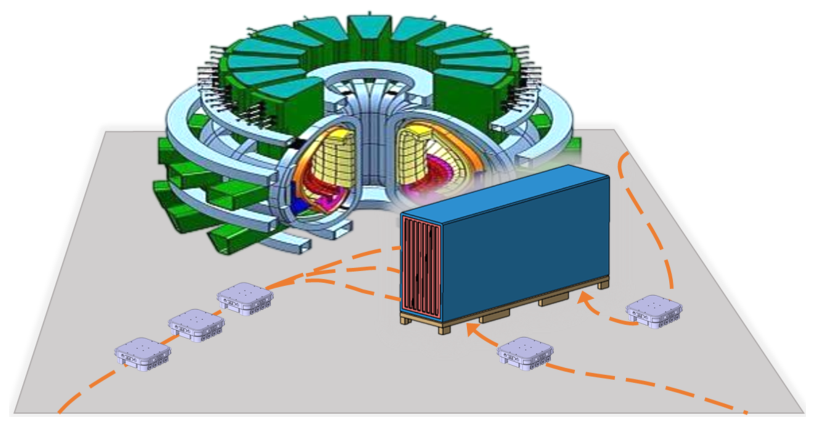
Figure 2.
Ex-vessel transportation system under operation scenario.
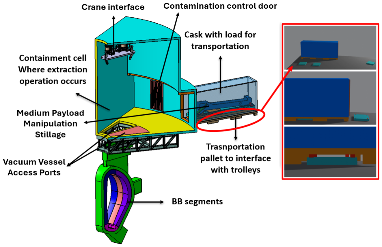
Figure 3.
Ex-vessel transportation system architecture diagram.
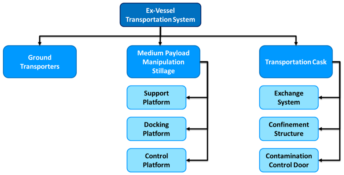
Figure 4.
Trolley base concept design without rescue system interfaces.
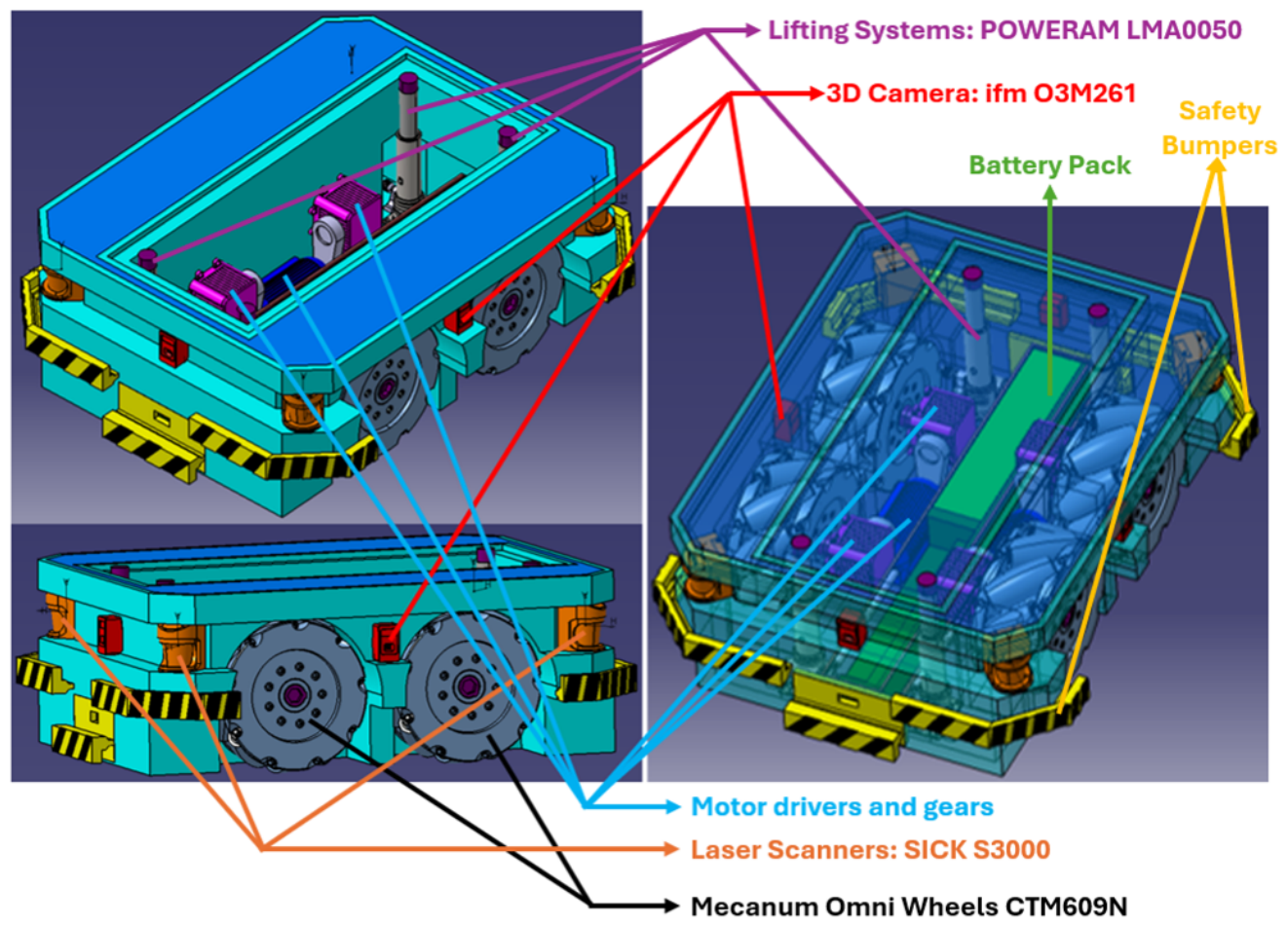
Figure 5.
(a) 3D Wheel Model. (b) 2D drafting of wheel [16].
Figure 5.
(a) 3D Wheel Model. (b) 2D drafting of wheel [16].
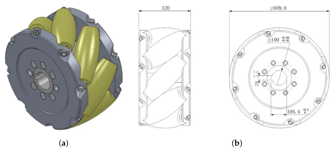
Figure 6.
SICK S3000 design diagram [22].
Figure 6.
SICK S3000 design diagram [22].
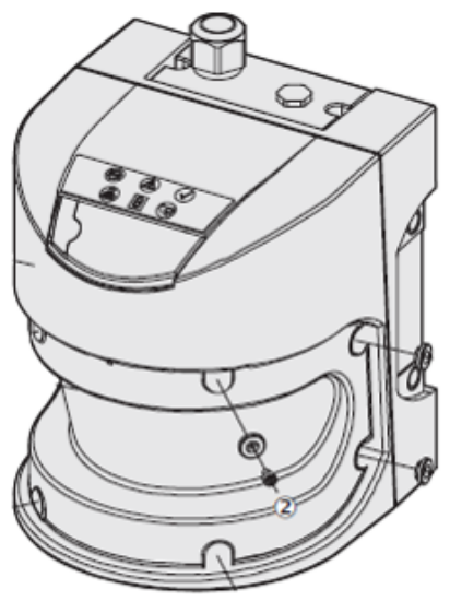
Figure 7.
3D Time-of-Flight Camera: ifm O3M261 design diagram [24].
Figure 7.
3D Time-of-Flight Camera: ifm O3M261 design diagram [24].
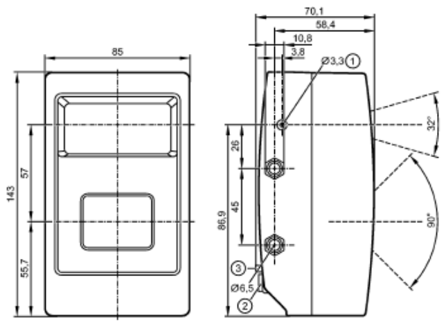
Figure 8.
Lifting system design diagram [25].
Figure 8.
Lifting system design diagram [25].
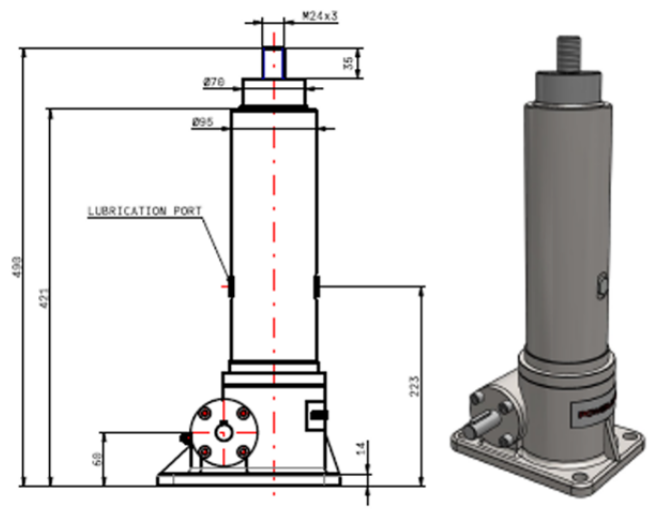
Figure 9.
(a) Total Displacement. (b) Stress Distribution.
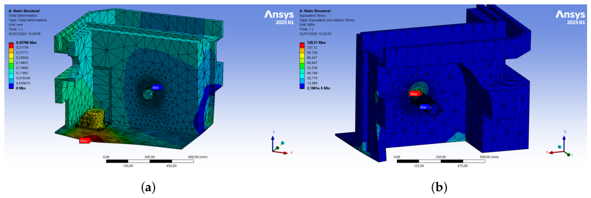
Figure 10.
Coupling sequence of the mechanical locking system: (a-d) insertion phases; (e-h) extraction phases.
Figure 10.
Coupling sequence of the mechanical locking system: (a-d) insertion phases; (e-h) extraction phases.
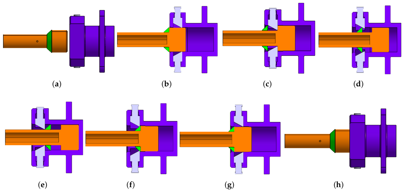
Figure 11.
(a) 1st Proposed Concept. (b) 2nd Proposed Concept.
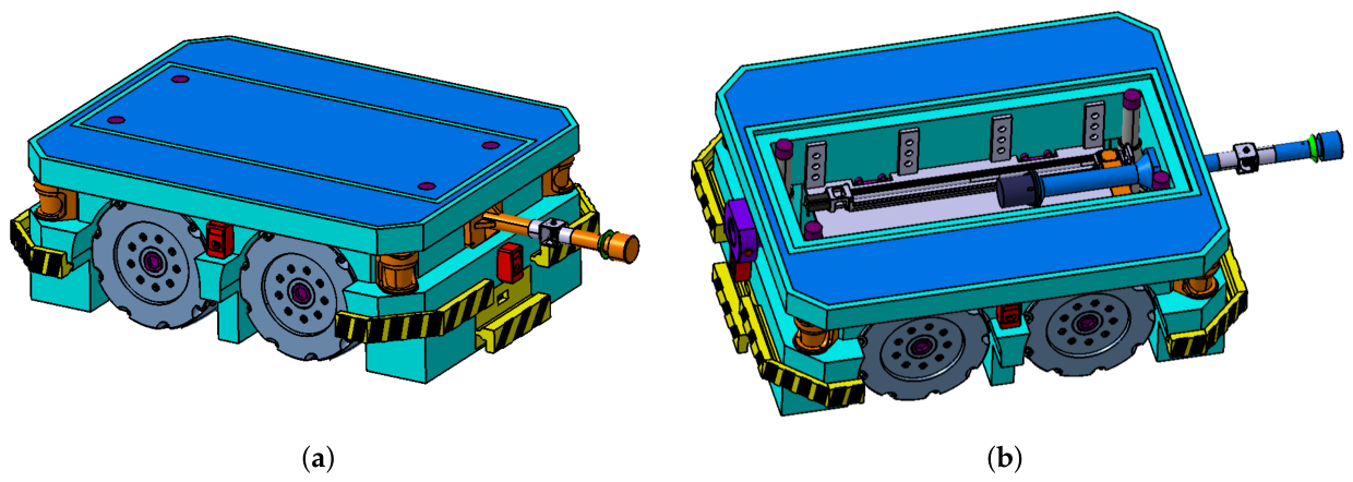
Figure 12.
Joint stress distribution, 35° towing configuration.
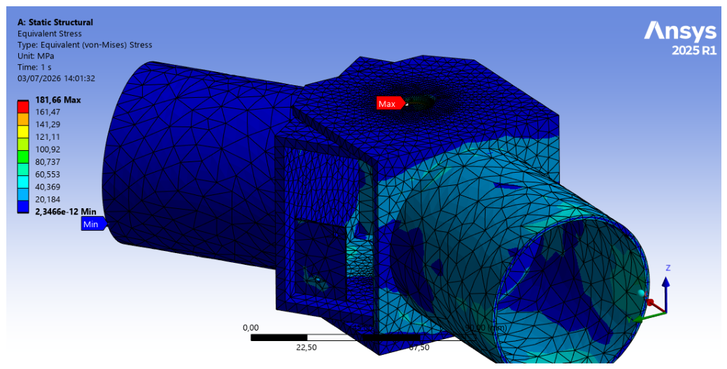
Figure 13.
Joint shear stress distribution, pushing configuration.
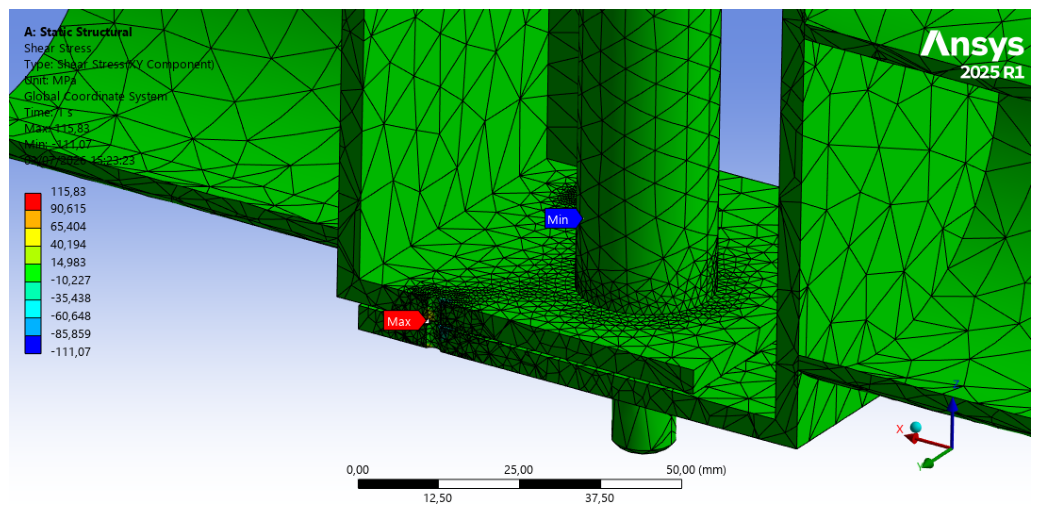
Figure 14.
(a) 1st modell stress distrubution. (b) 1st model maximum displacement.
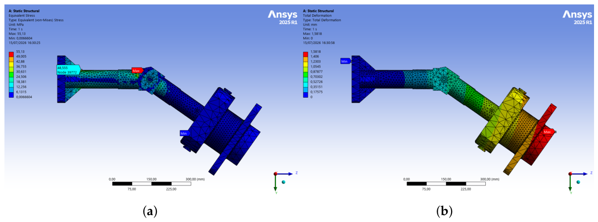
Figure 15.
(a) 2nd modell stress distrubution. (b) 2nd model maximum displacement.
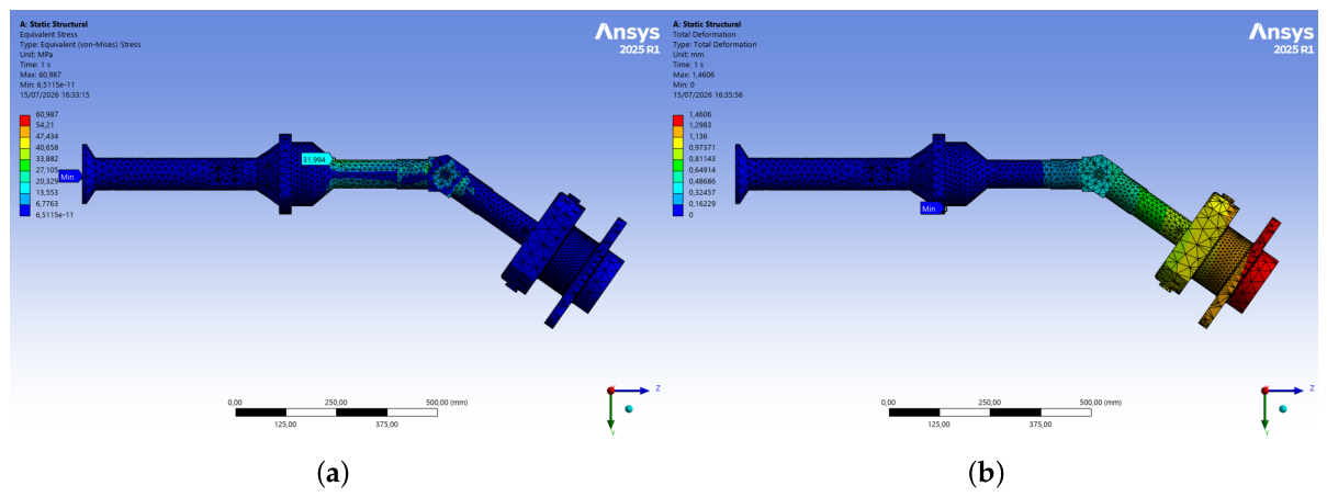
Figure 16.
Buckling 1st model.
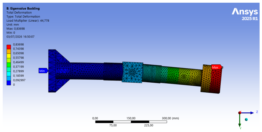
Figure 17.
Buckling 2nd model.
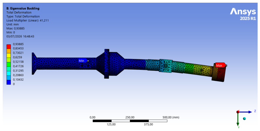

Table 1.
Capability assessment of representative commercial trolley-like systems, compared with the requirements of the DEMO ex-vessel trolley.
Table 1.
Capability assessment of representative commercial trolley-like systems, compared with the requirements of the DEMO ex-vessel trolley.
| System | Manufacturer | Payload | Payload/mass | Max. speed | Radiation tol. | Op. temp. | Footprint | Tandem- |
|---|---|---|---|---|---|---|---|---|
| (tons) | ratio | (m/s) | (Sv) | (°C) | (m2) | ready | ||
| MiR1350 | Mobile Industrial Robots | 1.35 | 2.45 | 1.2 | NA | 5–40 | 1.23 | No |
| P800 | Geek+ | 0.8 | 2.67 | 1.2 | NA | 0–45 | 0.96 | No |
| P1000 | Geek+ | 1.0 | 2.86 | 1.2 | NA | 0–45 | 0.96 | No |
| Max-N | AutoGuide | 1.2 | 1.00 | 1.2 | NA | 5–45 | 1.26 | No |
| Freight500 | Fetch Robotics | 0.5 | 1.00 | 1.5 | NA | 5–40 | 1.08 | No |
| Freight1500 | Fetch Robotics | 1.5 | 1.50 | 1.5 | NA | 5–40 | 1.08 | No |
| OTTO 1500 | OTTO Motors | 1.5 | 1.00 | 1.2 | NA | 5–40 | 1.17 | No |
| AMR | Locus Robotics | 0.2 | 0.63 | 1.5 | NA | 5–40 | 0.54 | No |
| STILL ACH Series | STILL | 0.6 | 1.00 | 1.2 | NA | 5–40 | 0.96 | No |
| HMI GPR Robot | HMI Technologies | 0.2 | 0.25 | 1.0 | 1 | 0–50 | 0.99 | No |
| ALROV-2000 | ALROV Robotics | 0.5 | 0.56 | 1.0 | 5 | 5–45 | 0.96 | No |
| V-SMART | Neura Robotics | 0.3 | 0.50 | 1.2 | 2 | –40 | 0.88 | No |
| PF3 | Stäubli WFT | 3 | 3.75 | 1.6 | NA | 5–40 | 2.50 | Yes |
| PF10 | Stäubli WFT | 10 | 3.70 | 1.1 | NA | 5–40 | NA | Yes |
| PF210 | Stäubli WFT | 30 | ∼3.7† | 1.3 | NA | 5–40 | 7.56 | Yes |
| PF230 | Stäubli WFT | 20 | ∼3.7† | 1.6 | NA | 5–40 | 12.88 | Yes |
| PF280 | Stäubli WFT | 60 | ∼3.7† | NA | NA | 5–40 | 11.35 | Yes |
| PF300 | Stäubli WFT | 450 | ∼3.7† | NA | NA | 5–40 | NA | Yes |
| omniMove | KUKA | 90 | NA | 1.0 | NA | NA | NA | Yes |
| MaxMover CB D 2000 | Oceaneering | 2 | NA | 2.0 | NA | NA | NA | No |
| ODM | AGILOX | 1.5 | NA | 1.4 | NA | NA | NA | No |
| W500SL | Wellwit Robotics | 0.5 | 2.27 | NA | NA | NA | NA | No |
| COTS range | — | 0.2–450 | 0.25–3.75 | 1.0–2.0 | 1–5 | –50 | 0.54–12.9 | — |
| Required (trolley) | — | ∼20 | >10 | 1.0–1.5 | ≫10/h | up to ∼50 | ∼3.5 | Yes |
NA: not available / not rated. †Mass not published by the manufacturer; payload/mass ratio estimated from Stäubli’s published PF3 and PF10 figures (≈3.7:1). Footprint is the plan area (length × width). Payload/mass ratio is payload divided by vehicle self-mass (higher is better). Tandem-ready denotes cooperative transport of a single load by coupled units.
Disclaimer/Publisher’s Note: The statements, opinions and data contained in all publications are solely those of the individual author(s) and contributor(s) and not of MDPI and/or the editor(s). MDPI and/or the editor(s) disclaim responsibility for any injury to people or property resulting from any ideas, methods, instructions or products referred to in the content. |
© 2026 by the authors. Licensee MDPI, Basel, Switzerland. This article is an open access article distributed under the terms and conditions of the Creative Commons Attribution (CC BY) license (http://creativecommons.org/licenses/by/4.0/).
Copyright: This open access article is published under a Creative Commons CC BY 4.0 license, which permit the free download, distribution, and reuse, provided that the author and preprint are cited in any reuse.


