

Submitted:
20 July 2026
Posted:
20 July 2026
You are already at the latest version
Abstract
The Z-source inverter (ZSI) has emerged as an effective single-stage power conversion topology for renewable energy applications owing to its inherent capability to perform both voltage buck and boost operations. However, the shoot-through states required to achieve voltage boosting introduce additional harmonic distortion that can degrade output power quality and increase the dependence on passive filtering. This paper presents a comparative performance analysis of conventional and strategic PWM shoot-through placement within the Maximum Boost Control (MBC) framework for three-phase Z-source inverters. A strategic shoot-through placement approach, referred to as Modified Maximum Boost Control (MMBC), is proposed to redistribute shoot-through intervals without compromising the voltage boost capability. Both control strategies were modelled and evaluated in MATLAB/Simulink under identical operating conditions. Their performance was assessed using Voltage Total Harmonic Distortion (THDV), voltage gain, and boost factor as the primary evaluation metrics. The simulation results indicate that the proposed MMBC achieved a minimum THDV of approximately 1.69%, compared with 4.05% obtained using conventional MBC. The improved harmonic performance was accompanied by a reduction in the output voltage magnitude, highlighting the trade-off between power quality enhancement and voltage utilisation. These findings demonstrate that strategic PWM shoot-through placement can substantially enhance the power quality of Z-source inverters and reduce harmonic filtering requirements, making the proposed approach suitable for renewable energy conversion applications.
Keywords:
maximum boost control
; modified maximum boost control
; pulse width modulation
; shoot-through placement
; total harmonic distortion (THD)
; Z-source inverter
1. Introduction
The increasing deployment of renewable energy systems has intensified the demand for efficient and reliable power electronic converters capable of delivering high-quality electrical power [1]. Renewable energy technologies, particularly photovoltaic (PV) and wind energy systems, require power conversion interfaces that not only provide efficient energy transfer but also maintain acceptable power quality under varying operating conditions [1,2]. Consequently, inverter topologies that combine high voltage conversion capability with reduced circuit complexity have become an important area of research [2].
Among the available converter topologies, the Z-source inverter (ZSI) has emerged as an attractive alternative to conventional Voltage Source Inverters (VSIs) and Current Source Inverters (CSIs) [3]. Unlike traditional inverter topologies, the ZSI employs a unique impedance network that permits intentional shoot-through switching states without damaging the semiconductor devices. This characteristic enables the converter to perform voltage buck and boost operations within a single power conversion stage, eliminating the need for an additional DC-DC boost converter while improving system flexibility and reliability [3].
The voltage boosting capability of the ZSI is achieved by introducing shoot-through intervals into the Pulse Width Modulation (PWM) switching sequence [4]. During these intervals, both switches within the same inverter leg are intentionally turned on simultaneously, allowing energy to be transferred through the impedance network and increasing the inverter output voltage [4]. Although this operating principle offers significant advantages, the inclusion of shoot-through states also influences the harmonic characteristics of the output waveform. Excessive harmonic distortion degrades power quality, increases filtering requirements, and may reduce compliance with grid interconnection standards, particularly in renewable energy applications where stringent harmonic limits must be satisfied [5].
Several PWM techniques have been proposed to enhance the operational performance of Z-source inverters, with Maximum Boost Control (MBC) being widely adopted because of its superior voltage boosting capability and effective utilisation of the available shoot-through interval [4]. Existing research has primarily focused on improving boost performance, modulation range, and voltage conversion efficiency. Comparatively less attention has been devoted to investigating how the temporal distribution of shoot-through states within the PWM switching cycle influences harmonic performance. Consequently, the potential benefits of strategically positioning shoot-through intervals to improve output power quality while preserving the inherent voltage boosting capability of the MBC technique remain insufficiently explored.
This paper addresses this research gap by introducing a strategic PWM shoot-through placement approach within the conventional MBC framework. The proposed implementation, referred to as MMBC, strategically redistributes shoot-through intervals throughout the PWM switching sequence while maintaining the fundamental operating principles of conventional MBC. The performance of the conventional MBC and the proposed MMBC strategies is evaluated under identical operating conditions using MATLAB/Simulink.
The comparative analysis is conducted using Voltage Total Harmonic Distortion (THDV), voltage gain, and boost factor as the principal performance indicators. The results demonstrate that the proposed MMBC significantly improves output voltage quality while maintaining the voltage boosting capability of the impedance source inverter. By enhancing power quality without introducing additional hardware or increasing converter complexity, the proposed strategy provides a practical solution for renewable energy power conversion systems requiring efficient voltage boosting and reduced harmonic distortion.
The principal contributions of this paper are summarised as follows:
- A strategic PWM shoot-through placement method is developed within the Maximum Boost Control framework.
- A Modified Maximum Boost Control (MMBC) strategy is introduced as a strategic implementation of conventional MBC.
- A comparative performance evaluation between conventional MBC and the proposed MMBC is conducted under identical operating conditions.
- The influence of strategic shoot-through placement on voltage gain, boost factor, and Voltage Total Harmonic Distortion (THDV) is quantitatively assessed.
- The proposed MMBC demonstrates a substantial reduction in harmonic distortion while preserving the voltage boosting capability of the Z-source inverter.
2. Literature Review
Pulse Width Modulation (PWM) techniques play a significant role in determining the performance of Z-source inverters (ZSIs) by controlling the generation of shoot-through states required for voltage boosting [6]. Unlike conventional Voltage Source Inverters (VSIs), which prohibit simultaneous conduction of the upper and lower switches within the same inverter leg, the ZSI employs an impedance network that safely permits shoot-through operation [3]. During the shoot-through interval, energy is stored in the impedance network and subsequently transferred to increase the dc-link voltage, enabling the inverter to perform both voltage buck and boost operations within a single conversion stage [3]. This unique operating principle has made the ZSI an attractive topology for photovoltaic systems, wind energy conversion, and other renewable energy applications.
Although the shoot-through operating mode provides the voltage boosting capability that distinguishes the ZSI from conventional inverter topologies, it also influences the harmonic characteristics of the output voltage waveform [3]. The insertion of shoot-through intervals modifies the inverter switching sequence, which may increase Voltage Total Harmonic Distortion (THDV) and consequently degrade output power quality [6]. Increased harmonic distortion often necessitates larger passive filters to satisfy grid interconnection standards, thereby increasing system cost and complexity [5]. Consequently, considerable research has focused on developing PWM strategies that achieve an appropriate balance between voltage boosting capability and harmonic performance [4,7].
Several PWM strategies have been reported in the literature for controlling Z-source inverters, including Constant Boost Control (CBC), Simple Boost Control (SBC), and Maximum Boost Control (MBC). These techniques differ primarily in the manner in which shoot-through intervals are generated and distributed throughout the switching period. SBC is recognised for its simple implementation but provides limited voltage boosting capability. CBC improves voltage utilisation through third-harmonic injection while maintaining a constant shoot-through duty ratio [7]. Among these conventional approaches, Maximum Boost Control has received considerable attention because it fully utilises the available zero switching states to maximise the boost factor without requiring additional hardware [4].
The popularity of Maximum Boost Control stems from its ability to achieve superior voltage gain while maintaining a relatively simple control structure [4]. By allocating shoot-through intervals to every available zero state, MBC maximises the voltage boosting capability of the Z-source inverter and has therefore become one of the most widely adopted PWM strategies in both research and practical applications [8]. However, the conventional implementation of MBC is primarily designed to maximise voltage gain rather than improve harmonic performance [4]. As a result, the temporal distribution of shoot-through states is fixed according to the conventional switching sequence, and limited consideration has been given to whether an alternative placement of these intervals could improve the quality of the output voltage waveform [9].
Previous investigations have generally evaluated Maximum Boost Control using performance indicators such as boost factor, modulation index, voltage gain, switching stress, and Total Harmonic Distortion (THD) [4,8,10]. While these studies have contributed significantly to improving the operating characteristics of the Z-source inverter, the majority have concentrated on determining the appropriate magnitude and duration of shoot-through intervals. Comparatively fewer studies have investigated whether the location of shoot-through intervals within the PWM switching sequence can be strategically manipulated to enhance power quality while preserving the voltage boosting capability of the converter.
Motivated by this observation, this study investigates the influence of strategic PWM shoot-through placement within the Maximum Boost Control framework. Rather than modifying the boost mechanism or introducing additional switching hardware, the proposed approach strategically redistributes the existing shoot-through intervals while maintaining the fundamental operating principles of conventional MBC [4]. This strategic implementation is referred to as Modified Maximum Boost Control (MMBC). A comparative performance analysis between the conventional MBC and the proposed MMBC is conducted using MATLAB/Simulink under identical operating conditions [11]. The evaluation focuses on Voltage Total Harmonic Distortion (THDV), voltage gain, and boost factor to determine whether strategic shoot-through placement can improve output power quality without compromising the voltage boosting capability of the Z-source inverter [10].
3. Methodology
This study evaluates the influence of strategic Pulse Width Modulation shoot-through placement on the performance of a three-phase impedance source inverter operating under the MBC strategy. Rather than introducing a new converter topology or modifying the voltage boosting mechanism, the proposed approach strategically redistributes the shoot-through intervals within the PWM switching sequence while preserving the conventional operating principle of Maximum Boost Control [4]. This strategic implementation is referred to as Modified Maximum Boost Control (MMBC).
To ensure a fair comparison, both the conventional MBC and the proposed MMBC were implemented using an identical three-phase Z-source inverter model developed in MATLAB/Simulink [11]. The two control strategies were evaluated under identical operating conditions so that any observed differences in performance could be attributed solely to the placement of shoot-through intervals.
- A.
- Development of the Reference Z-Source Inverter Model.
A reference three-phase Z-source inverter model was developed in MATLAB/Simulink to provide a common platform for evaluating both control strategies [11]. The simulation model consists of a DC voltage source, a symmetrical impedance network comprising inductors and capacitors, a three-phase inverter bridge, and a balanced three-phase load, as illustrated in Figure 1.
The impedance network permits safe shoot-through operation by limiting the short-circuit current while simultaneously storing and releasing energy to achieve voltage boosting. During shoot-through operation, energy is accumulated in the impedance network and subsequently transferred to increase the dc-link voltage supplied to the inverter bridge [3]. This operating principle enables single-stage buck-boost power conversion and forms the basis for implementing both the conventional MBC and the proposed MMBC strategies.
- B. Conventional Maximum Boost Control.
The conventional MBC strategy was first implemented to establish a reference model for performance evaluation. MBC achieves the highest voltage boosting capability by utilising every available zero switching state to generate shoot-through intervals within each switching cycle [4]. This approach maximises the boost factor while maintaining a relatively simple control structure [4].
The conventional implementation follows the established PWM switching sequence, where the temporal location of the shoot-through intervals is fixed according to the carrier comparison process [4,6]. The resulting output voltage, voltage gain, and harmonic performance serve as the benchmark against which the proposed strategy is evaluated.
- C. Proposed Modified Maximum Boost Control (MMBC).
The proposed Modified Maximum Boost Control (MMBC) retains the fundamental operating principle of conventional MBC while introducing a strategic redistribution of shoot-through intervals within the PWM switching sequence. Unlike the conventional method, which inserts shoot-through intervals at predetermined zero states [4], the proposed strategy deliberately relocates these intervals to positions that improve the harmonic characteristics of the output voltage without altering the overall shoot-through duty ratio.
Since only the temporal placement of the shoot-through intervals is modified, the converter topology, impedance network, modulation index, switching frequency, and voltage boosting mechanism remain unchanged. Consequently, the influence of strategic shoot-through placement can be evaluated independently of other converter parameters.
The implementation sequence of the proposed MMBC algorithm is illustrated in Figure 2. At the first stage, the conventional PWM switching pattern is obtained by comparing the three-phase reference signals with a carrier waveform [6]. The shoot-through generation block subsequently redistributes the shoot-through intervals according to the proposed placement strategy before the final gating signals are applied to the inverter switches.
- D. Performance Evaluation
The performance of the conventional MBC and the proposed MMBC strategies was evaluated using identical simulation conditions in MATLAB/Simulink. To ensure a consistent comparison, all inverter parameters, impedance network components, DC input voltage, switching frequency, load conditions, and modulation index were maintained constant throughout the investigation.
The comparative analysis was performed using three principal performance indicators:
- Voltage Total Harmonic Distortion (THDV)
- Voltage Gain
- Boost Factor
Voltage harmonic distortion was determined using Fast Fourier Transform (FFT) analysis of the inverter output voltage, while the voltage gain and boost factor were obtained directly from the simulation measurements. The measured results obtained using MMBC were then compared with those of the conventional MBC to quantify the influence of strategic PWM shoot-through placement on inverter performance.
4. Results and Discussion
The performance of the proposed Modified Maximum Boost Control (MMBC) strategy was evaluated against the conventional Maximum Boost Control (MBC) using the reference three-phase Z-source inverter model described in Section III. Both controllers were simulated in MATLAB/Simulink under identical operating conditions, including the DC input voltage, modulation index, switching frequency, impedance network parameters, and load. The comparative analysis focused on the influence of strategic PWM shoot-through placement on output voltage quality, voltage utilisation, and harmonic performance.
- Output Voltage Waveform Analysis
Figure 3 presents the steady-state three-phase output voltage waveforms obtained using the proposed MMBC strategy, whereas Figure 4 shows the corresponding output waveforms generated by the conventional MBC controller.
Both controllers maintain balanced three-phase operation and preserve the inherent voltage boosting mechanism of the Z-source inverter. However, noticeable differences are observed in both the waveform quality and the output voltage magnitude. The proposed MMBC produces a smoother and more sinusoidal output waveform with visibly reduced waveform distortion. At the same time, the output voltage magnitude is lower than that obtained using the conventional MBC strategy under identical simulation conditions.
Unlike the conventional MBC implementation, which generates shoot-through intervals whenever zero switching states become available, the proposed MMBC strategically redistributes these intervals within the PWM switching sequence. Although the total shoot-through mechanism remains unchanged, the modified temporal placement influences the interaction between the switching sequence and the fundamental output voltage component. Consequently, the proposed strategy achieves improved waveform quality while altering the effective output voltage magnitude.
The observations obtained from the output waveforms indicate that strategic shoot-through placement affects not only the harmonic characteristics of the inverter output but also the voltage utilisation achieved under Maximum Boost Control. This demonstrates that the temporal distribution of shoot-through intervals plays an important role in determining the overall performance of the Z-source inverter.
- Electrical Performance Analysis
The electrical performance of both control strategies was evaluated over a modulation index range of 0.6–1.0 while maintaining a constant DC input voltage of 600 V. The measured DC-link voltage, boost factor, RMS output voltage, and Voltage Total Harmonic Distortion (THDV) obtained using the proposed MMBC are summarised in Table 1.
Although the output voltage increased as the modulation index increased, the resulting RMS voltage remained lower than that obtained using the conventional MBC strategy. These results indicate that strategic shoot-through placement influences the effective output voltage utilisation while preserving the inherent voltage boosting capability of the Maximum Boost Control strategy.
The corresponding electrical performance obtained using the conventional MBC strategy is presented in Table 2.
Table 2 demonstrates that the conventional MBC follows the expected relationship between modulation index and boost factor. The controller achieved a minimum THDV of approximately 4.05% at a modulation index of 0.9. Compared with the proposed MMBC, the conventional controller produced a higher RMS output voltage but also exhibited considerably greater harmonic distortion.
A direct comparison between Table 1 and Table 2 shows that the proposed MMBC reduced THDV by approximately 58%, decreasing it from 4.05% to 1.69% under identical operating conditions. The improvement in harmonic performance was accompanied by a reduction in the effective output voltage magnitude, indicating that strategic redistribution of shoot-through intervals influences both harmonic suppression and voltage utilisation.
- Harmonic Spectrum Analysis
The output voltage harmonic spectra obtained using Fast Fourier Transform (FFT) analysis are presented in Figure 5 and Figure 6 for the proposed MMBC and the conventional MBC strategies, respectively.
The FFT spectra provide further insight into the harmonic behaviour of both control strategies at a modulation index of 0.6. The proposed MMBC exhibits a dominant fundamental frequency component together with a Voltage Total Harmonic Distortion (THDV) of approximately 6.9%, whereas the conventional MBC produces a THDV of approximately 4.4% under the same operating conditions.
Although the proposed MMBC produces a higher THDV at this operating point, the harmonic spectra demonstrate that the influence of strategic shoot-through placement varies with the modulation index. This observation is consistent with the quantitative results presented in Table 1 and Table 2, where the performance of both controllers was evaluated over the complete modulation index range.
The tabulated results show that the proposed MMBC achieves its best harmonic performance at a modulation index of 0.9, where the minimum THDV of approximately 1.69% is obtained compared with 4.05% for the conventional MBC. These findings indicate that the effectiveness of strategic shoot-through placement is dependent on the operating point and should therefore be evaluated over a range of modulation indices rather than at a single operating condition.
5. Conclusions
This paper presented a comparative performance analysis of conventional MBC and the proposed MMBC for a three-phase impedance source inverter. The proposed MMBC was developed by strategically redistributing shoot-through intervals within the conventional PWM switching sequence while preserving the inherent Maximum Boost Control operating principle.
A comparative evaluation was conducted using MATLAB/Simulink under identical operating conditions. The performance of both control strategies was assessed using Voltage Total Harmonic Distortion (THDV), voltage gain, and boost factor as the principal performance indicators. The simulation results demonstrated that the proposed MMBC significantly improves harmonic performance at appropriate operating conditions, achieving a minimum THDV of approximately 1.69% compared with 4.05% obtained using the conventional MBC strategy. The analysis also showed that the effectiveness of strategic PWM shoot-through placement varies with the modulation index, indicating that harmonic performance is dependent on the selected operating point.
Although the proposed MMBC produced a lower effective output voltage magnitude than the conventional MBC under identical simulation conditions, both controllers preserved the inherent voltage boosting capability of the Maximum Boost Control strategy. This observation suggests that strategic redistribution of shoot-through intervals influences voltage utilisation while maintaining the fundamental boost mechanism of the Z-source inverter.
Overall, the findings demonstrate that the temporal placement of shoot-through intervals plays an important role in determining the harmonic characteristics and voltage utilisation of Maximum Boost-Controlled Z-source inverters. The proposed MMBC therefore provides an alternative control strategy for applications where improved power quality is prioritised, while also highlighting the trade-off between harmonic suppression and output voltage magnitude.
Future work will focus on extending the proposed MMBC strategy by investigating its influence on output current harmonic distortion (THDI) under different operating conditions and load characteristics. A comprehensive evaluation of both voltage and current harmonic performance will provide a more complete assessment of the proposed controller for practical grid-connected and renewable energy applications. Furthermore, optimisation of the shoot-through placement algorithm will be investigated to improve harmonic performance while enhancing voltage utilisation. Finally, experimental validation using a hardware prototype will be conducted to verify the simulation results under practical operating conditions.
Author Contributions
Conceptualization, Tusetso Rethabile Johannes; Methodology, Tusetso Rethabile Johannes; Software, Tusetso Rethabile Johannes; Validation, Tusetso Rethabile Johannes; Formal analysis, Tusetso Rethabile Johannes; Investigation, Tusetso Rethabile Johannes; Data curation, Tusetso Rethabile Johannes; Writing—original draft, Tusetso Rethabile Johannes; Writing—review & editing, Musasa Kabeya and Mbulelo Perfect Ngongoma; Visualization, Tusetso Rethabile Johannes; Supervision, Musasa Kabeya and Mbulelo Perfect Ngongoma. All authors have read and agreed to the published version of the manuscript.
Funding
This research received no external funding.
Data Availability Statement
The original contributions presented in this study are included in the article. Further inquiries can be directed to the corresponding author.
Conflicts of Interest
The authors declare no conflict of interest.
References
- Teodorescu, R.; Liserre, M.; Rodríguez, P. Grid Converters for Photovoltaic and Wind Power Systems; John Wiley & Sons: Chichester, U.K., 2011. [Google Scholar]
- Mohan, N.; Undeland, T. M.; Robbins, W. P. Power Electronics: Converters, Applications, and Design, 3rd ed.; John Wiley & Sons: Hoboken, NJ, USA, 2003. [Google Scholar]
- Peng, Z. Z-Source Inverter. IEEE Trans. Ind. Appl. 2003, vol. 39(no. 2), 504–510. [Google Scholar] [CrossRef]
- Peng, Z.; Shen, M.; Qian, Z. Maximum Boost Control of the Z-Source Inverter. IEEE Trans. Power Electron. 2005, vol. 20(no. 4), 833–838. [Google Scholar] [CrossRef]
- IEEE Power; Energy Society. IEEE Std 519-2022: IEEE Recommended Practice and Requirements for Harmonic Control in Electric Power Systems; IEEE. New York, NY, USA, 2022.
- Holmes, G.; Lipo, T. A. Pulse Width Modulation for Power Converters: Principles and Practice; John Wiley & Sons: Hoboken, NJ, USA, 2003. [Google Scholar]
- Shen, M.; Wang, J.; Joseph, A.; Peng, F. Z.; Tolbert, L. M.; Adams, D. J. Constant Boost Control of the Z-Source Inverter to Minimize Current Ripple and Voltage Stress. Conf. Rec. IEEE Industry Applications Society Annual Meeting, Seattle, WA, USA, 2004; pp. 1422–1427. [Google Scholar]
- Gyawali; Ajmal, A.; Liu, W.; Yang, Y. A Review on Modulation Techniques of Quasi-Z-Source Inverter for Grid-Connected Photovoltaic Systems. *E-Prime-Adv. Electr. Eng. Electron. Energy* 2024, vol. 10, Art.(no. 100809). [Google Scholar] [CrossRef]
- Pires, V. F.; Cordeiro, A.; Foito, D.; Roncero-Clemente, C.; Romero-Cadaval, E.; Silva, J. F. Improved Carrier-Based Modulation for the Single-Phase T-Type qZ-Source Inverter. Electronics 2024, vol. 13(no. 6, Art. no. 1113). [Google Scholar] [CrossRef]
- Rauf, T.; Furqan, M.; Zulifqar, S.; Rafiq, S. Implementation and Performance Analysis of Z Source Inverter with Space Vector PWM Technique with Low THD Factor and High Gain. J. Electr. Electron. Eng. 2022, vol. 10(no. 3), 95–103. [Google Scholar]
- MathWorks, “MATLAB and Simulink,” Natick, MA, USA. Available online: https://www.mathworks.com/products/simulink.html.
Figure 1.
MATLAB/Simulink implementation of the reference three-phase impedance source inverter (ZSI) model.
Figure 1.
MATLAB/Simulink implementation of the reference three-phase impedance source inverter (ZSI) model.
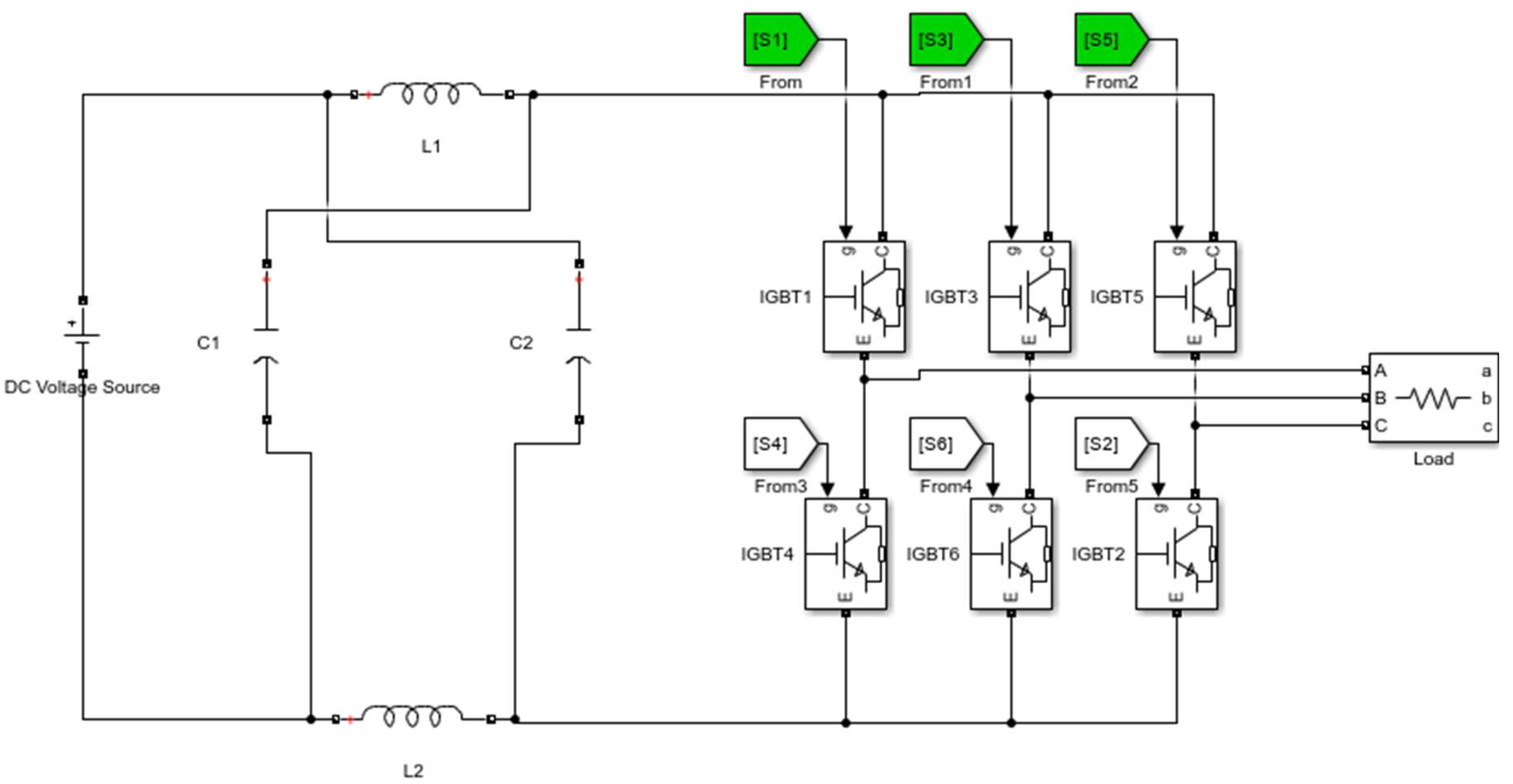
Figure 2.
Proposed strategic shoot-through state placement algorithm.

Figure 3.
Three-phase output voltage using the proposed MMBC.
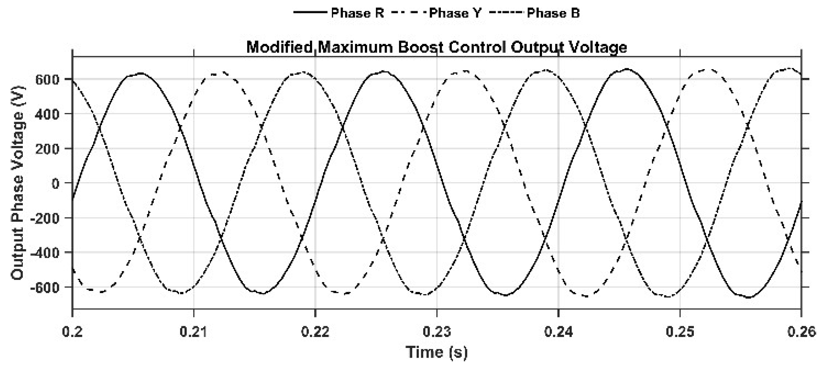
Figure 4.
Three-phase output voltage using the conventional MBC.
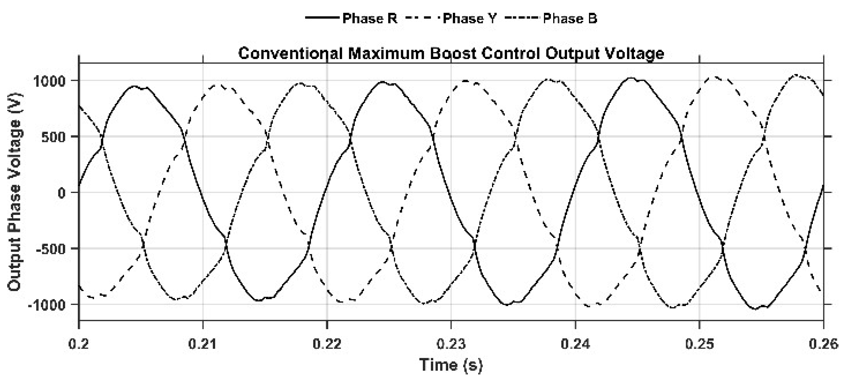
Figure 5.
FFT spectrum of the proposed MMBC (0.6).
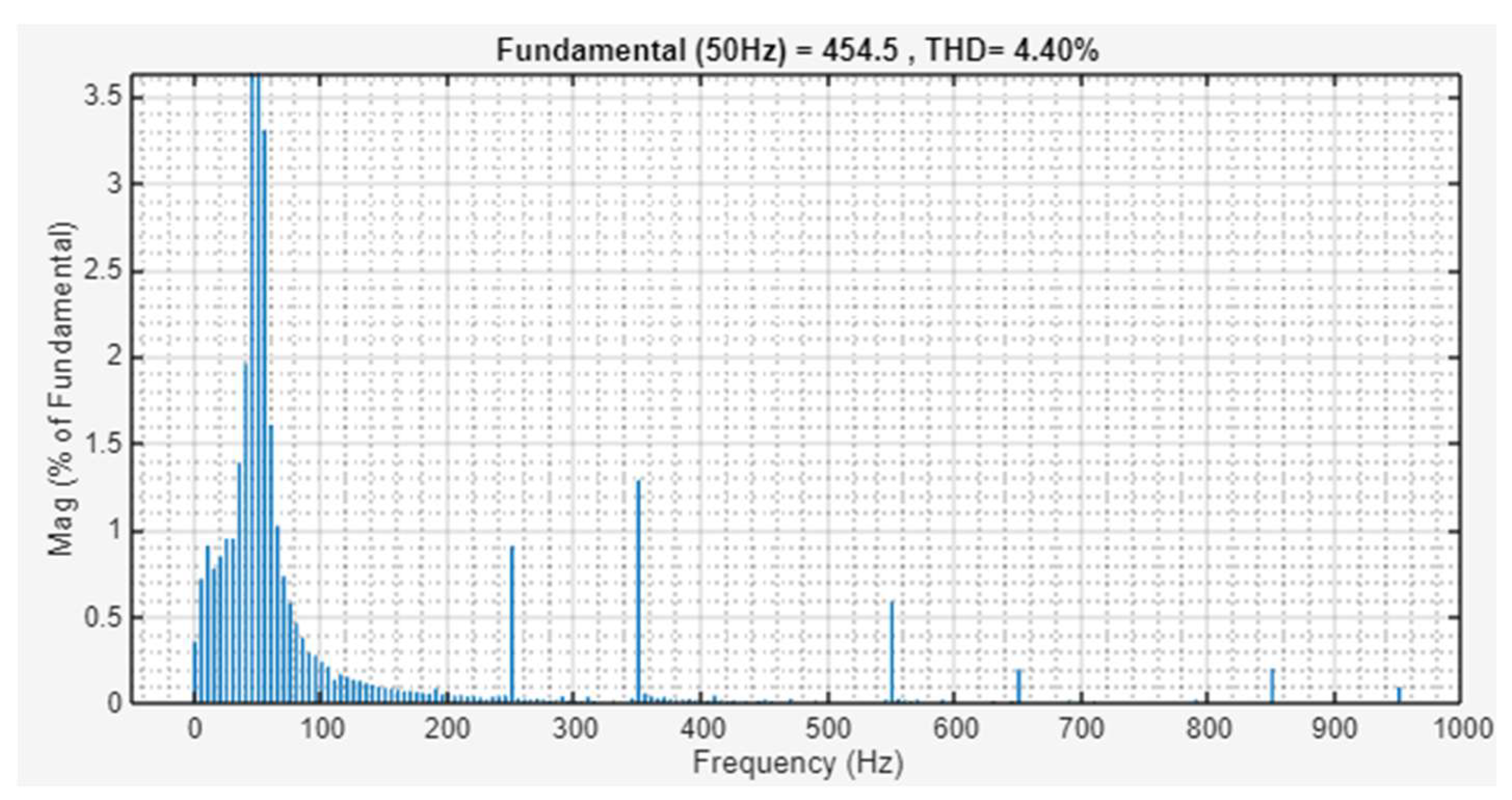
Figure 6.
FFT spectrum of the conventional MBC (M=0.6).
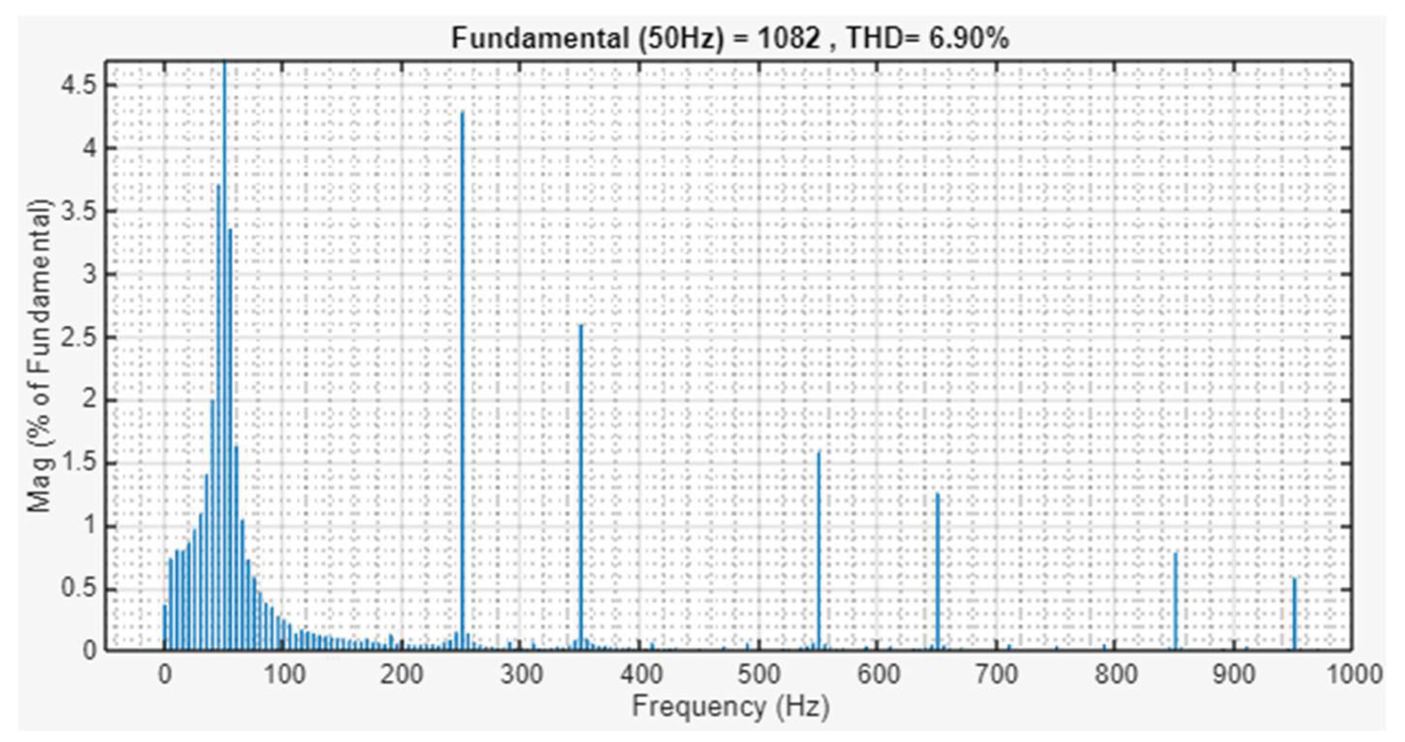

Table 1.
Electrical Performance of the Proposed MMBC.
| Modified MBC | |||||
| M | 0.6 | 0.7 | 0.8 | 0.9 | 1 |
| B | 3.5 | 2.6 | 2.1 | 1.8 | 1.5 |
| VIN | 600 | 600 | 600 | 600 | 600 |
| VDC-LINK | 2000 | 2000 | 1700 | 1600 | 2100 |
| VAC PH RMS | 318 | 410 | 495 | 566 | 700 |
| %THD | 4.4 | 3.2 | 2.24 | 1.69 | 3.97 |
Table 2.
(A) Continued M = 0.6. (B) Electrical Performance of the Conventional MBC. (C) Continued M = 0.6.
Table 2.
(A) Continued M = 0.6. (B) Electrical Performance of the Conventional MBC. (C) Continued M = 0.6.
| (A) | |||||
| VIN | 200 | 300 | 400 | 500 | 700 |
| VDC-LINK | 780 | 1100 | 1500 | 1900 | 2800 |
| VAC PH RMS | 106 | 163 | 226 | 283 | 424 |
| (B) | |||||
| MBC | |||||
| M | 0.6 | 0.7 | 0.8 | 0.9 | 1 |
| B | 3.5 | 2.6 | 2.1 | 1.8 | 1.5 |
| VIN | 600 | 600 | 600 | 600 | 600 |
| VDC-LINK | 2100 | 2100 | 1700 | 1500 | 1500 |
| VAC PH RMS | 778 | 919 | 1061 | 1202 | 2200 |
| %THD | 6.9 | 5.76 | 4.76 | 4.05 | 4.71 |
| (C) | |||||
| VIN | 200 | 300 | 400 | 500 | 700 |
| VDC-LINK | 780 | 1100 | 1500 | 1900 | 2800 |
| VAC PH RMS | 283 | 600 | 800 | 1000 | 1400 |
Disclaimer/Publisher’s Note: The statements, opinions and data contained in all publications are solely those of the individual author(s) and contributor(s) and not of MDPI and/or the editor(s). MDPI and/or the editor(s) disclaim responsibility for any injury to people or property resulting from any ideas, methods, instructions or products referred to in the content. |
© 2026 by the authors. Licensee MDPI, Basel, Switzerland. This article is an open access article distributed under the terms and conditions of the Creative Commons Attribution (CC BY) license (http://creativecommons.org/licenses/by/4.0/).
Copyright: This open access article is published under a Creative Commons CC BY 4.0 license, which permit the free download, distribution, and reuse, provided that the author and preprint are cited in any reuse.


