

Submitted:
18 July 2026
Posted:
20 July 2026
You are already at the latest version
Abstract
Rapid, reliable, and energy-efficient data collection is essential for disaster response, where terrestrial communication networks are often disrupted or unavailable. Unmanned Aerial Vehicles (UAVs) provide a flexible solution for collecting critical sensing data, but their operation is constrained by limited onboard energy, stochastic wireless conditions, complex three-dimensional environments, and stringent latency requirements. This paper proposes a structured multi-UAV framework for disaster-response data collection that separates the optimisation process into spatial, temporal, and safety layers. In the spatial layer, three-dimensional Travelling Salesman Problem with Neighbourhoods (3D-TSPN) modelling allows UAVs to collect sensor data by entering sensing regions rather than visiting exact sensor coordinates. An Age of Information (AoI)-aware Genetic Algorithm (GA) is then used to optimise the sensor visiting order, while RRT-Connect verifies obstacle-aware feasible paths in the 3D environment. In the temporal layer, a Lyapunov-based control mechanism makes binary computation decisions between local processing and offloading to a single MEC node, balancing delay, energy consumption, AoI, and queue stability. In the safety layer, continuous-time conflict detection and temporal offset resolution are used to monitor inter-UAV separation and obstacle-related risks. The proposed framework is evaluated through simulation under wireless, mobility, computation, and obstacle constraints. The results show that the framework achieves a 100% data collection success rate, zero obstacle collisions, zero inter-UAV collisions, and no dropped tasks. Compared with planning-oriented and MEC-oriented baselines, the proposed framework improves information freshness, average delay, processing delay, energy efficiency, and system cost, while maintaining reliable multi-UAV coordination in a complex 3D environment. In addition, the layered design clarifies the role of each component: 3D-TSPN improves spatial flexibility, AoI-aware GA enhances route ordering, RRT-Connect supports obstacle-aware path feasibility, Lyapunov-based binary offloading stabilises computation decisions, and safety monitoring improves operational reliability. These findings demonstrate that a simplified layer-based integration of mobility planning, computation control, and safety monitoring can provide an effective solution for multi-UAV disaster-response data collection in complex 3D environments.
Keywords:
Unmanned Aerial Vehicles (UAVs)
; disaster response
; aerial data collection
; 3D-TSPN
; Age of Information (AoI)
; AoI-aware genetic algorithm
; RRT-Connect
; Lyapunov optimisation
; binary MEC offloading
; queue stability
; 3D path planning
; multi-UAV coordination
; collision monitoring
1. Introduction
Background
Unmanned Aerial Vehicles (UAVs) have become indispensable assets in modern disaster management due to their ability to rapidly deploy, hover, and navigate unsafe or inaccessible environments [1,2] . Their inherent mobility enables critical operations such as search and rescue, rapid damage assessment, real-time surveillance, and temporary communication restoration in scenarios where terrestrial infrastructure is partially or completely impaired [3,4,5]. When integrated with Internet of Things (IoT) ecosystems, UAVs act as airborne data collectors and relay platforms, connecting isolated sensor networks with emergency command and control centres [6,7]. Prior studies have demonstrated the effectiveness of UAVs in disaster scenarios where they often provide the only feasible sensing and communication capability when ground infrastructure fails [1,2].
Beyond direct sensing, UAVs enhance situational awareness by serving as airborne gateways in IoT-enabled disaster-response systems. They aggregate data from distributed ground sensors and relay it to command centres or edge infrastructure, thereby improving operational visibility and decision-making. In Public Safety Communications (PSC), UAVs can temporarily replace disrupted terrestrial nodes, preserving network continuity during infrastructure failures [3]. To further improve responsiveness and scalability, Mobile Edge Computing (MEC) has been explored as an enabling technology. MEC reduces latency by placing computation closer to UAVs and sensors [8,9].
Despite these advances, disaster environments impose severe and interdependent constraints on UAV operations [5,10,11]. These include complex three-dimensional (3D) obstacle fields caused by collapsed structures and debris; strict energy limitations that constrain flight endurance and sensing capabilities; stochastic wireless communication links affected by interference and infrastructure damage; and stringent latency requirements that demand fresh, timely situational information. In addition, reliable multi-UAV coordination is required to ensure safe separation and collision-free operation during concurrent missions. Addressing these challenges requires UAV systems to simultaneously plan feasible trajectories, guarantee sensor coverage, collect and process data, offload computation when beneficial, and operate safely under uncertainty.
This work introduces a clear separation between spatial path planning, temporal computation control, and safety monitoring, while coupling these layers within a single execution framework. Spatial decisions, including sensing-neighbourhood coverage, sensor visitation order, obstacle avoidance, and trajectory feasibility, are handled using a three-dimensional Travelling Salesman Problem with Neighbourhoods (3D-TSPN) formulation, an Age of Information (AoI)-aware Genetic Algorithm (GA), and RRT-Connect-based path-feasibility checking. Temporal decisions, including task processing and local-versus-MEC execution, are addressed using Lyapunov-based optimisation [12]. Unlike conventional approaches that treat mobility planning and computation control independently or sequentially, the proposed framework links spatial and temporal modules through shared system states, enabling coordinated and adaptive decision-making during mission execution. This design preserves analytical clarity while avoiding inefficiencies associated with loosely coupled or post-processed integration strategies.
Recent research has investigated UAV-assisted disaster response from multiple complementary perspectives, including path planning, communication efficiency, computation offloading, and information freshness. Sampling-based motion planners such as RRT and its variants provide geometric feasibility in complex three-dimensional environments; however, they are primarily designed for collision avoidance and kinematic feasibility and do not consider temporal performance metrics such as latency, queue dynamics, or data freshness [13,14]. Metaheuristic optimisation techniques, including Genetic Algorithms and swarm-based methods, have been widely applied to UAV routing and coverage problems due to their ability to handle large combinatorial search spaces. Nevertheless, these approaches typically optimise distance or energy metrics and do not explicitly integrate AoI-aware routing with queue-stable computation control [15,16].
In parallel, AoI has emerged as a key metric for quantifying data freshness in time-sensitive networks. Foundational work on AoI focuses primarily on temporal update policies and queueing models, without considering UAV mobility or geometric path planning [17]. Although AoI optimisation has been incorporated into UAV-assisted wireless networks, practical integration with obstacle-aware 3D path planning and geometric feasibility constraints remains underdeveloped in existing resource optimisation frameworks [1,2].
MEC has also been extensively studied in the context of UAV networks to reduce latency and balance energy consumption. Lyapunov-based optimisation frameworks have proven effective for stabilising task queues and optimising delay–energy trade-offs under stochastic conditions. Despite their theoretical strength, existing Lyapunov-based MEC models typically assume abstracted or fixed mobility patterns and do not account for detailed UAV path planning or obstacle-avoidance mechanisms [18].
This work is motivated by the need for a unified optimisation pipeline that reflects how disaster missions actually operate. UAVs must process and transmit heterogeneous, time-sensitive sensor data, such as survivor localisation signals, gas leak alerts, and structural vibration readings, under fluctuating network conditions and strict timeliness constraints. Therefore, the system must not only generate safe 3D trajectories and guarantee coverage, but also regulate computation and communication decisions in real time to prevent queue instability and excessive delay. To address this, we adopt a Lyapunov drift-plus-penalty control layer that dynamically balances delay, energy consumption, AoI, and queue stability through binary local/MEC processing decisions, and we couple it with AoI-aware spatial planning that prioritises freshness during routing and execution. This design ensures that data timeliness is treated as an operational requirement that drives decisions throughout the mission, rather than as a metric evaluated only after completion.
This work provides a comprehensive framework for multi-UAV disaster-response operations. The main contributions of the proposed system are summarised as follows:
- 1)
- A three-dimensional Travelling Salesman Problem with Neighbourhoods (3D-TSPN) model is developed, in which each ground sensor is represented by a sensing neighbourhood to guarantee robust data collection while preserving spatial flexibility in obstacle-rich environments.
- 2)
- An AoI-aware Genetic Algorithm (GA) is proposed to optimise the sensor visitation sequence within the spatial layer by considering flight time, cumulative AoI, coverage feasibility, and path smoothness, while computation and offloading decisions are handled separately by the temporal control layer.
- 3)
- A three-dimensional RRT-Connect planner is integrated to verify and generate obstacle-aware feasible paths between sensing neighbourhoods using conservatively inflated obstacle models, ensuring practical flight feasibility under safety constraints.
- 4)
- A Lyapunov-based temporal control layer is introduced to stabilise UAV task queues and dynamically select between local processing and binary MEC offloading to a single MEC node, balancing delay, energy consumption, AoI, and queue stability under stochastic wireless conditions.
- 5)
- A simple multi-UAV safety monitoring mechanism is developed using continuous-time conflict detection, safety buffers, closest-approach distance metrics, temporal desynchronisation, and basic speed-adjustment-based resolution to support safe concurrent UAV operation.
These contributions establish a unified spatial–temporal optimisation architecture that is mathematically grounded, operationally realistic, and well-suited to highly dynamic disaster environments. The remainder of this paper is organised as follows. Section II reviews related work on UAV path planning, MEC integration, AoI-aware optimisation, and multi-UAV coordination. Section III presents the system model, including UAV mobility, sensing, communication, binary MEC offloading, queue dynamics, AoI evolution, and safety constraints. Section IV develops the Lyapunov-based binary offloading model and the corresponding control policy. Section V presents the layered multi-UAV framework, including 3D-TSPN sensing-neighbourhood modelling, AoI-aware GA sequencing, RRT-Connect path feasibility checking, and safety monitoring. Section VI describes the simulation setup and parameters. Section VII presents the experimental evaluation, including baseline comparisons, ablation analysis, and benchmark comparisons. Finally, Section VIII concludes the paper and outlines future research directions.
2. Related Work and Research Gap
This section reviews the most relevant prior work directly related to the proposed multi-UAV disaster-response framework, with emphasis on path planning, AoI-aware sensing, MEC-assisted computation, and multi-UAV coordination. The focus is placed on identifying the specific limitations that motivate the proposed layered spatial–temporal optimisation architecture.
2.1. UAV Path Planning and Coverage
UAV-assisted disaster-response systems have been widely investigated for rapid sensing, damage assessment, search-and-rescue support, and emergency communication restoration in infrastructure-impaired environments. Existing path-planning approaches can be broadly grouped into sampling-based, metaheuristic, and neighbourhood-based coverage methods.
Sampling-based planners such as RRT, RRT*, and PRM are highly effective for generating collision-free paths in cluttered three-dimensional spaces [13,14,19], but they primarily address local geometric feasibility and do not optimise global sensing order or information freshness. In contrast, metaheuristic methods such as Genetic Algorithms (GA), Particle Swarm Optimisation (PSO), and other swarm-based techniques provide strong global search capability for routing and task sequencing [20,21,22,23]. However, these approaches often focus on combinatorial ordering while abstracting away obstacle-aware execution and detailed 3D motion feasibility.
Neighbourhood-based formulations, such as the Travelling Salesman Problem with Neighbourhoods (TSPN), are particularly relevant to UAV data collection because UAVs do not always need to visit exact sensor coordinates [24,25,26]. Instead, a sensor can be considered successfully collected when the UAV enters its sensing region. This provides greater spatial flexibility, especially in obstacle-rich disaster environments. However, most existing TSPN-based UAV planning methods focus mainly on trajectory distance or energy consumption and do not explicitly integrate AoI, computation delay, or queue stability into the planning loop [26,27,28].
This limitation motivates the proposed spatial layer, which combines 3D-TSPN sensing-neighbourhood modelling, AoI-aware GA-based sensor sequencing, and RRT-Connect path feasibility checking. The purpose is not only to generate short routes, but also to produce freshness-aware and obstacle-feasible trajectories suitable for realistic disaster-response missions.
2.2. AoI-Aware Sensing and MEC Offloading
Age of Information (AoI) has emerged as a critical metric for disaster monitoring, where stale sensor updates can degrade situational awareness and delay emergency response [17,29,30]. Existing AoI-aware UAV studies have shown that freshness-driven scheduling significantly improves monitoring quality. However, AoI is frequently treated as a post-routing performance metric rather than a variable that actively shapes trajectory decisions during path planning [25,29,31].
In parallel, Mobile Edge Computing (MEC) has been widely used to reduce latency in UAV-assisted IoT systems by enabling task offloading and edge-side processing [9,32,33]. Prior optimisation frameworks have explored local-versus-edge computation trade-offs using convex optimisation, mixed-integer programming, and Lyapunov-based control. Nevertheless, many MEC models assume simplified or fixed UAV mobility patterns and do not interact directly with obstacle-aware 3D path planning [32,35,36].
The key limitation in existing work is the weak coupling between sensing freshness, queue backlog evolution, wireless channel quality, and UAV movement. In practical disaster missions, these factors are interdependent: the path followed by a UAV affects the collection time of each sensor, the wireless link quality at collection time, the feasibility of MEC offloading, and the resulting AoI and queue dynamics. This motivates the proposed Lyapunov-based temporal control layer, which selects between local processing and binary MEC offloading to a single MEC node while balancing delay, energy consumption, AoI, and queue stability.
2.3. Multi-UAV Coordination and Layered Optimisation
Multi-UAV disaster-response missions introduce additional complexity through concurrent sensing, trajectory overlap, and inter-UAV collision risk [37,38,39]. Existing solutions include rule-based deconfliction, Multi-Agent Path Finding (MAPF), Conflict-Based Search (CBS), and time-expanded grid planners. While these methods can provide formal safety guarantees, they often rely on discretised environments that reduce realism in continuous three-dimensional disaster spaces [37,38,39].
Layered optimisation frameworks that combine global route optimisation with local motion planning have emerged as a practical alternative. These systems improve feasibility and scalability by separating high-level task sequencing from low-level path generation. However, most existing designs still treat spatial planning, MEC offloading, AoI management, and conflict resolution as loosely coupled stages.
In contrast, the proposed framework adopts a structured layered design in which route sequencing, obstacle-aware connectivity, queue-aware binary offloading, and continuous-time conflict monitoring operate through shared system states. This design maintains modular clarity while enabling interaction between spatial, temporal, and safety-related decisions during mission execution.
2.4. Research Gap
The most important gap in the current literature is the lack of a unified framework that jointly addresses coverage-guaranteed routing, obstacle-aware 3D motion feasibility, AoI-driven sensing priority, MEC-assisted computation offloading, queue stability, and multi-UAV safety.
Existing studies typically optimise only one or two of these dimensions at a time. For example, path-planning studies often focus on distance minimisation or obstacle avoidance without considering queue stability or computation delay. AoI-aware studies commonly improve data freshness but may abstract away realistic 3D motion constraints. MEC-offloading studies often optimise delay and energy but assume simplified UAV mobility. Similarly, multi-UAV coordination methods may improve safety but do not necessarily account for AoI, MEC decisions, or task queue evolution.
To address this gap, this work proposes a layered spatial–temporal optimisation framework that integrates 3D-TSPN coverage modelling, AoI-aware GA-based sensor sequencing, RRT-Connect path feasibility checking, Lyapunov-based queue-stable binary MEC offloading, and continuous-time conflict monitoring within a single decision architecture. The resulting framework provides a clearer separation of responsibilities across the spatial, temporal, and safety layers while preserving the interaction required for realistic multi-UAV disaster-response operations.
3. System Model
This section provides the mathematical formalisation of the UAV-assisted disaster-response system. The model captures UAV mobility, sensing-neighbourhood coverage, data generation, local and MEC-assisted task processing, wireless communication, queue evolution, AoI dynamics, and energy consumption. The subsequent optimisation modules, including AoI-aware GA sequencing, RRT-Connect path feasibility checking, and Lyapunov-based binary MEC offloading, operate on this model.
We consider a three-dimensional disaster region of dimensions , which contains N static ground sensors, U concurrently deployed UAVs, a set of obstacles , and a single Mobile Edge Computing (MEC) node located at . The set of UAVs is denoted by , and the set of sensors is denoted by .
UAVs are required to collect data from all assigned sensors, maintain safe navigation in a 3D obstacle-rich environment, and decide whether each collected task should be processed locally or offloaded to the MEC node.
3.1. UAV Mobility Model
Each UAV operates under the following discrete-time kinematic model:
where and denote the position and velocity of UAV i at time t, respectively. The UAV velocity is constrained by
where is the maximum allowable UAV speed [4].
For obstacle and safety modelling, each obstacle is inflated by a safety margin :
where denotes a ball of radius . This inflation provides a conservative representation of obstacles and supports robust collision avoidance under modelling and localisation uncertainty.
3.2. Sensing and Coverage Model
Each ground sensor is located at position . Instead of requiring the UAV to visit the exact sensor coordinate, each sensor is associated with a sensing neighbourhood:
where is the sensing radius.
A sensor j is considered successfully collected by UAV i if
This transforms the coverage problem into a three-dimensional Travelling Salesman Problem with Neighbourhoods (3D-TSPN), where the UAV must visit sensing regions rather than exact sensor coordinates. This formulation increases spatial flexibility and allows the planner to select feasible collection points that avoid obstacles while still satisfying sensing requirements [24,25,26].
3.3. Task Processing and Binary MEC Offloading Model
Each sensor j generates a data task of size bits with a processing deadline . Once the task is collected by a UAV, it can be processed in one of two modes:
where
Thus, the computation model is binary: each task is either processed locally or fully offloaded to the MEC node. Partial offloading is not considered in this framework.
3.3.1. Local Processing
For local processing, the required number of CPU cycles for task j is
where is the number of CPU cycles required per bit. If UAV i has local computational capacity , the local processing delay is
The corresponding local computation energy is modelled as
where denotes the computation power of UAV i.
3.3.2. MEC Offloading
When a task is offloaded to the MEC node, the uplink transmission rate from UAV i to the MEC node is expressed as
where is the available bandwidth, is the transmission power, is the channel gain, is the noise power, and is the interference level [4,5,11].
The transmission delay for task j is
The MEC processing delay is
where denotes the CPU capacity of the MEC node.
Therefore, the total MEC-assisted processing delay is
The communication energy consumed during offloading is
A task is considered feasible under mode only if its delay and energy requirements can be satisfied within the current UAV battery and deadline constraints.
3.4. Queueing and Task Arrival Model
Each UAV maintains a task queue , which represents the accumulated computation workload awaiting service. The task arrival process is determined by the data collection events along the UAV path, the revisit intervals of sensors, and the stochastic communication conditions.
The queue evolves according to
where is the service rate achieved by the selected processing mode. Since the offloading decision is binary, depends on whether the task is processed locally or offloaded to the MEC node:
The stochastic queue is stabilised by the Lyapunov-based temporal controller described in the following sections.
3.5. Age of Information Model
Age of Information (AoI) is used to quantify the freshness of the collected sensor data. Let denote the most recent successful update time of sensor j. The AoI of sensor j at time t is defined as
When a UAV successfully enters the sensing neighbourhood of sensor j and collects its data, the update time is refreshed. The AoI is then reset according to
In the proposed framework, two related AoI measures are considered. The collection-level AoI, defined in (18) and (19), is reset when a UAV enters the sensing neighbourhood and successfully collects the sensor update. This measure is used by the spatial layer and incorporated into the GA fitness function to prioritise freshness-aware sensor visitation. In the temporal layer, a completion-time AoI cost is calculated by including the additional delay caused by local processing or MEC offloading. This cost is used to compare the two binary processing modes. Therefore, the spatial layer prioritises timely data collection, while the temporal layer prioritises the timely completion of collected tasks.
3.6. Energy Consumption Model
The overall energy consumption of each UAV consists of flight energy, communication energy, and onboard computation energy. The total energy consumption of UAV i is modelled as
where , , and denote flight, communication, and local computation energy components, respectively.
The flight energy is related to the mission flight time and UAV propulsion power:
where denotes the UAV flight or hovering power and is the total flight time.
The communication energy consumed for offloading task j is
The onboard computation energy for local processing is
The UAV battery constraint is expressed as
where denotes the initial energy capacity of UAV i.
3.7. End-to-End Delay Model
The end-to-end delay of a collected task consists of the processing delay and, if offloaded, the transmission delay. For task j collected by UAV i, the total delay is modelled as
The task is feasible if
This delay model is incorporated into the Lyapunov drift-plus-penalty framework to jointly minimise latency-related cost and maintain queue stability.
3.8. Safety and Collision Constraints
For safe multi-UAV operation, the minimum separation between any two UAVs must satisfy
where is the required inter-UAV safety distance.
Obstacle avoidance is enforced by ensuring that UAV positions and path segments do not intersect the inflated obstacle set:
These constraints are monitored during mission execution using continuous-time conflict detection and safety-buffer checking.
3.9. Integration with the Layered Optimisation Framework
The proposed system model serves as the mathematical foundation for the complete layered spatial–temporal optimisation pipeline. The sensing-neighbourhood model directly supports the 3D-TSPN formulation for coverage-guaranteed sensor visitation. Based on this representation, the AoI-aware GA optimises the sensor visitation sequence by considering flight time, cumulative AoI, coverage feasibility, and path smoothness. For each inter-neighbourhood transition, the RRT-Connect module verifies and generates geometrically feasible three-dimensional paths under inflated obstacle constraints.
In parallel, the Lyapunov-based temporal control layer dynamically selects between local processing and binary MEC offloading according to queue backlog, delay, energy consumption, AoI, and wireless channel conditions. At the safety layer, continuous closest-approach monitoring, temporal desynchronisation, and safety-buffer constraints are employed to detect and mitigate inter-UAV conflicts during simultaneous mission execution.
Through this structured interaction between coverage modelling, freshness-aware route optimisation, obstacle-aware path feasibility, binary computation offloading, and conflict monitoring, the proposed framework establishes a tightly coupled yet clearly separated spatial–temporal architecture for resilient and scalable UAV-assisted disaster response.
4. Lyapunov-Based Optimisation Framework
This section develops the Lyapunov-based temporal optimisation model for UAV task execution and binary MEC offloading. The objective is to stabilise each UAV task queue while selecting, for each collected task, whether it should be processed locally or fully offloaded to a single MEC node. The temporal layer therefore complements the spatial planning layer by controlling computation and communication decisions after data collection events occur.
Lyapunov optimisation is particularly suitable for disaster-response environments, where wireless channel quality, task arrivals, UAV positions, and available energy are stochastic. In the proposed framework, the Lyapunov controller does not optimise the UAV route directly. Instead, it receives collection events from the spatial layer and makes queue-aware local/MEC processing decisions based on delay, energy consumption, AoI, and queue backlog.
4.1. Queue Evolution
Each UAV maintains a task queue , representing the accumulated workload awaiting processing. The queue evolves as
where is the task arrival process induced by sensor collection events, and is the service rate achieved by the selected processing mode.
Since the proposed computation model is binary, each task is either processed locally or fully offloaded to the MEC node. Therefore, the service rate is defined as
where , denotes local processing, and denotes MEC offloading.
4.2. Lyapunov Function and Drift
To analyse queue stability, we define the quadratic Lyapunov function as
where is the vector of UAV task queues.
The conditional one-step Lyapunov drift is given by
Minimising the Lyapunov drift encourages queue stability by preventing unbounded backlog growth. However, in disaster-response missions, queue stability alone is insufficient because the system must also minimise delay, energy consumption, and information staleness. Therefore, a drift-plus-penalty formulation is used.
4.3. Drift-Plus-Penalty Objective
Let denote the instantaneous cost associated with the selected processing mode for UAV i. This cost combines energy consumption, processing delay, and AoI:
where is the energy consumed by the selected mode, is the corresponding task completion delay, is the resulting AoI-related cost, and , , and are weighting coefficients.
The drift-plus-penalty objective is then written as
where is the Lyapunov control parameter. A larger value of V places greater emphasis on reducing energy-delay-AoI cost, while a smaller value of V prioritises queue reduction and system responsiveness.
Using the standard quadratic queue bound, the drift can be upper-bounded as
where B is a finite constant obtained from the bounded second moments of arrivals and service rates.
Substituting this bound into the drift-plus-penalty expression gives
Since B and are independent of the processing decision at the current slot, the per-slot controller only needs to minimise the terms that depend on the selected local/MEC mode.
4.4. Per-Task Binary Offloading Decision
For each collected task, the controller evaluates two candidate processing modes: local processing and MEC offloading. The local mode is feasible only if the local processing delay and energy consumption satisfy the task deadline and UAV battery constraints:
Similarly, MEC offloading is feasible only if the wireless link is available and the total offloading delay and communication energy satisfy
where is the transmission delay, is the MEC processing delay, and is the remaining UAV energy after accounting for flight and previously processed tasks.
For each feasible mode , we define the instantaneous penalty as
The candidate queue state under mode m is
The corresponding one-step drift approximation is
The Lyapunov objective for mode m is then
The binary processing decision is selected as
subject to the feasibility of each mode. If only one mode is feasible, the controller selects that mode. If neither local processing nor MEC offloading is feasible, the task is marked as dropped:
This decision rule ensures that the controller favours the processing option that best balances queue reduction, delay, energy consumption, and AoI at the time of data collection.
Figure 1 illustrates the role of the Lyapunov-based binary offloading layer. After task collection, this layer makes the temporal processing decision by selecting either local UAV processing or MEC offloading according to queue backlog, delay, energy, and processing feasibility.
4.5. Local Processing Cost
For local processing, the task execution delay is
where is the required number of CPU cycles for the collected task and is the UAV onboard CPU capacity.
The local computation energy is expressed as
where is the UAV computation power.
The AoI-related value under local processing is calculated based on the collection time and local execution delay:
where is the time at which the corresponding sensor data is collected.
4.6. MEC Offloading Cost
For MEC offloading, the uplink transmission rate is
where is the available bandwidth, is the transmission power, is the channel gain, is the noise power, and is the interference.
The transmission delay is
where is the data size of task j collected by UAV i.
The MEC-side processing delay is
where denotes the CPU capacity of the MEC node.
Therefore, the total offloading delay is
The transmission energy is
The AoI-related value under MEC offloading is
4.7. Queue Stability Guarantee
The proposed controller follows the standard drift-plus-penalty principle [12,32]. If there exists at least one feasible policy that can stabilise the UAV task queues under the considered arrival process, then the drift-plus-penalty minimising policy ensures strong queue stability.
Theorem 1. If the task arrival rates are within the stability region and at least one feasible stationary policy exists, then the proposed Lyapunov-based binary offloading controller satisfies
Furthermore, the achieved time-average cost satisfies
where is the optimal time-average cost under an ideal stationary policy, B is the Lyapunov drift bound constant, and V is the control parameter.
This bound shows the classical cost optimality gap. Increasing V improves asymptotic cost performance but can increase the average queue backlog, whereas decreasing V promotes faster queue reduction and lower delay at the cost of higher energy or AoI-related penalty.
4.8. Summary
The Lyapunov-based optimisation framework provides the temporal decision layer of the proposed multi-UAV system. Unlike formulations that optimise CPU frequency, partitioning ratios, or multiple MEC server selection, the proposed model adopts a simplified binary decision structure. Each collected task is either processed locally or fully offloaded to a single MEC node, while infeasible tasks are dropped. This simplification improves interpretability and aligns the temporal layer with the overall layered framework: the spatial layer determines where and when data are collected, the temporal layer determines how collected tasks are processed, and the safety layer monitors conflict-free multi-UAV execution.
4.9. Interaction with the 3D-TSPN–GA–RRT-Connect Framework
The Lyapunov-based optimisation (LBO) module operates at the temporal execution stage to make queue-aware computation and binary MEC offloading decisions, while the 3D-TSPN–GA–RRT-Connect framework governs the spatial planning layer by determining the sensing-neighbourhood visitation sequence, guaranteeing coverage, and generating geometrically feasible obstacle-aware trajectories.
The interaction between the temporal and spatial layers is achieved through shared system states. Specifically, the spatial layer determines the collection time of each sensor, which directly affects the resulting Age of Information (AoI), task arrival process, and queue evolution. The AoI-aware Genetic Algorithm (GA) uses estimated visitation times to prioritise freshness-aware routing, while RRT-Connect ensures that each inter-neighbourhood transition is feasible in the 3D obstacle environment. After each collection event, the LBO module evaluates the current queue backlog, remaining UAV energy, wireless channel quality, and UAV–MEC distance to select either local processing or full offloading to the MEC node.
This coupling establishes a structured spatial–temporal optimisation framework in which trajectory planning, sensing freshness, queue stability, and computation offloading are coordinated during mission execution, while preserving a clear separation between the spatial planning and temporal control layers.
5. Layered Multi-UAV Framework
This section presents the proposed layered architecture integrating 3D-TSPN-based coverage modelling, AoI-aware Genetic Algorithm (GA) sequencing, RRT-Connect path feasibility checking, inflated obstacle avoidance, and multi-UAV safety monitoring. The framework is designed to operate reliably in complex disaster environments while maintaining a clear separation between spatial planning, temporal queue-aware optimisation, and safety monitoring.
5.1. Framework Overview
The proposed system consists of five coordinated phases:
- 1.
- Coverage Modelling using 3D-TSPN: Each ground sensor is represented by a 3D sensing neighbourhood, allowing the UAV to collect data without visiting the exact sensor coordinate.
- 2.
- AoI-aware GA-based Sequencing: An AoI-aware GA computes the visitation order of the assigned sensor neighbourhoods by considering flight time, cumulative AoI, coverage feasibility, and path smoothness.
- 3.
- RRT-Connect Path Feasibility Checking: For each leg in the GA solution, RRT-Connect is used to verify and generate feasible obstacle-aware 3D paths between sensing neighbourhoods.
- 4.
- Path Post-Processing: Generated paths are simplified, redundant waypoints are removed, and the final trajectories are resampled to support smooth and feasible UAV movement.
- 5.
- Multi-UAV Safety Monitoring: Continuous-time conflict detection, closest-approach distance checking, obstacle inflation margins, and temporal desynchronisation are used to support safe simultaneous UAV operation.
This layered structure enables robust global–local coordination while avoiding unnecessary algorithmic complexity.
Figure 3 illustrates the overall workflow of the proposed optimisation process. The process begins by initialising the disaster-response scenario, including UAVs, sensor nodes, obstacles, and the MEC node. A balanced zone-assignment step is then applied to distribute sensing tasks among UAVs. For each UAV, an AoI-aware genetic algorithm determines the sensor-visiting sequence, while the 3D-TSPN sensing model and RRT-Connect planner generate feasible obstacle-aware paths. After task collection, a Lyapunov-based binary offloading controller decides whether each task should be processed locally or offloaded to the MEC server. Finally, safety monitoring is performed before computing the final performance metrics, including coverage, delay, energy consumption, fairness, and system cost.
5.2. Balanced Zone Assignment
Before route sequencing, the sensing nodes are partitioned into balanced spatial zones and each zone is assigned to one UAV [40,41,42]. The objective is to distribute the sensing workload approximately evenly among the UAVs while preserving spatial locality. This assignment reduces unnecessary route overlap and prevents a single UAV from receiving a disproportionately large sensing workload. The balanced zone-assignment step is performed during mission initialisation before the AoI-aware GA is applied independently to the sensing neighbourhoods assigned to each UAV.
5.3. 3D-TSPN Coverage Formulation
As defined in Section III, each sensing region is represented by a sphere:
The objective is to find an ordered sequence
such that each sensor neighbourhood is visited at least once while minimising the spatial mission cost. The 3D-TSPN formulation is expressed as:
subject to:
Unlike conventional TSP formulations, the UAV is not required to visit the exact sensor coordinate. Instead, it only needs to enter the corresponding sensing neighbourhood. This provides additional spatial flexibility around obstacles and enables RRT-Connect to select feasible approach points within each neighbourhood.
Figure 4 illustrates that, unlike traditional point visiting, the proposed 3D-TSPN model allows the UAV to collect data once it enters the sensing neighbourhood, without visiting the exact sensor coordinate.
5.4. Genetic Algorithm Representation
In the proposed spatial layer, each GA chromosome is represented as a permutation of the assigned TSPN neighbourhood indices:
where M is the number of sensors assigned to the corresponding UAV. Each gene corresponds to one unique sensing neighbourhood, and the gene order defines the UAV visitation sequence. To preserve valid TSPN routing, repeated genes are not allowed.
The initial population of size P is generated using a mixed strategy combining random permutations, nearest-neighbour sequences, and greedy-randomised routes. This initialisation improves early solution quality while maintaining population diversity. In addition, AoI-related priority is reflected through the fitness function, enabling the GA to favour routes that reduce information staleness during mission execution.
5.5. AoI-Aware GA Fitness Function
The GA fitness function is designed to optimise the spatial layer only. It evaluates each candidate route according to flight time, cumulative AoI, and path smoothness. Computation energy, queue stability, and local/MEC offloading decisions are handled separately by the Lyapunov-based temporal layer.
For a chromosome , the implemented fitness function is defined as
where , , and are non-negative weighting coefficients associated with flight time, AoI, and trajectory smoothness, respectively.
The flight-time term is computed as
where is the total length of the RRT-Connect-generated route and is the UAV speed.
The cumulative AoI term is approximated using the estimated arrival time at each sensing neighbourhood:
where denotes the estimated time at which the UAV first enters the sensing neighbourhood of sensor . This term encourages the GA to prioritise routes that collect time-sensitive data earlier.
The smoothness term penalises abrupt changes in flight direction:
where is the turning angle between consecutive path segments and K is the number of evaluated turns.
Geometrically infeasible chromosomes are handled through hard rejection rather than a finite weighted penalty. Specifically, if a candidate path cannot be generated, contains fewer than two valid waypoints, or fails to cover any assigned sensing neighbourhood, it is excluded from the feasible candidate set by assigning
This also covers failed RRT-Connect transitions, since a chromosome is only evaluated after an obstacle-aware feasible path has been generated. Consequently, infeasible candidates cannot be selected as valid GA solutions.
This simplified fitness structure ensures that the GA remains focused on spatial route quality, while temporal computation decisions are made independently by the Lyapunov controller.
Figure 5 illustrates the role of the AoI-aware GA routing layer in the proposed framework. This layer focuses on spatial route planning by determining the UAV visiting sequence across sensing neighbourhoods while considering AoI, obstacles, and route feasibility.
5.6. GA Operators
To efficiently explore the permutation-based 3D-TSPN search space while preserving valid route structures, the GA employs selection, crossover, mutation, and elitism operators.
5.6.1. Selection
Tournament selection with replacement is adopted due to its robustness in multimodal search landscapes and its ability to maintain a balance between exploration and exploitation.
5.6.2. Crossover
To preserve permutation validity, ordered crossover (OX) is employed. Two crossover indices are randomly selected, the corresponding subsequence is inherited from the first parent, and the remaining genes are inserted according to their relative order in the second parent. This operator preserves high-quality subsequences while preventing duplicate neighbourhood assignments [21].
5.6.3. Mutation
To enhance diversity and mitigate premature convergence, adaptive swap mutation is applied. The mutation probability is adjusted according to recent fitness diversity, increasing when the population begins to stagnate and decreasing when sufficient exploration is observed.
5.6.4. Elitism
To preserve the best candidate routes across generations, the top elite chromosomes are directly copied into the subsequent population without modification.
5.7. Feasibility Repair Mechanisms
Following crossover and mutation, a repair mechanism is applied to ensure chromosome validity and route feasibility. First, duplicated genes are removed to preserve the permutation constraint. Next, any missing sensing neighbourhoods are reinserted using a greedy cost-aware selection strategy. Candidate sequences that lead to missed sensing neighbourhoods or repeated RRT-Connect failures are then locally adjusted by modifying the visitation order around the infeasible transition. This repair stage improves the likelihood that each chromosome corresponds to a valid 3D-TSPN-compliant sensing route that can be evaluated by the geometric planner.
5.8. RRT-Connect for Collision-Free Connectivity
For each consecutive pair of sensing neighbourhoods in the GA-optimised sequence, a bidirectional RRT-Connect planner is executed to generate a geometrically feasible and obstacle-aware three-dimensional transition path [13,14] .
To provide conservative safety margins, each obstacle is inflated as:
where ⊕ denotes the Minkowski sum, is the safety margin, and is a ball of radius .
The RRT-Connect planner employs a dual-tree expansion strategy in which one tree is extended toward a randomly sampled point, while the opposite tree attempts to connect to the newly generated node. Specifically, the Extend operation incrementally grows the active tree toward the sample, whereas the Connect operation advances the opposite tree until a connection is achieved or an obstacle constraint is encountered.
This bidirectional expansion accelerates path discovery in cluttered three-dimensional disaster environments compared with single-tree sampling methods and provides a practical feasibility check for the GA-generated sensing order.
Once a feasible path is obtained, post-processing is applied to improve flight efficiency and numerical consistency [43,44,45]. Specifically, redundant waypoint reduction and uniform path resampling are performed to remove unnecessary intermediate points and produce smoother UAV motion during execution.
5.9. Multi-UAV Conflict Detection and Resolution
To ensure safe simultaneous operation of multiple UAVs, inter-UAV separation is continuously monitored throughout mission execution. For any pair of UAVs i and j, the instantaneous separation distance is defined as:
A potential conflict is detected whenever the separation distance violates the minimum safety threshold:
5.9.1. Closest-Approach Computation
To reduce the risk of missed conflicts caused by discrete-time sampling, the minimum continuous-time closest-approach distance is evaluated over overlapping trajectory segments:
where denotes the temporal overlap interval between the two UAV trajectory segments. Whenever , the conflict is recorded and the safety module evaluates a mitigation action.
5.9.2. Resolution Actions
A simple conflict mitigation mechanism is used to preserve both safety and mission efficiency without modifying the global sensing sequence. First, temporal desynchronisation is applied by introducing start-time offsets between UAVs. If two UAVs still approach within the safety threshold during execution, a basic speed-adjustment action is applied to delay one UAV along its planned trajectory and increase temporal separation. In addition, inflated obstacle margins and continuous closest-approach monitoring are used to identify obstacle-related risks and buffer-zone intrusions.
This lightweight resolution strategy preserves the 3D-TSPN and GA-generated sensing order while supporting safe concurrent multi-UAV operation in continuous three-dimensional space.
Overall, the proposed layered architecture unifies global sequencing through AoI-aware GA, coverage flexibility through 3D-TSPN, obstacle-aware geometric feasibility through RRT-Connect, queue-stable binary computation control through LBO, and multi-UAV safety through continuous closest-approach conflict monitoring. This structured design establishes a resilient UAV-assisted disaster-response pipeline capable of operating reliably under uncertain and dynamic environmental conditions.
6. Simulation Setup
This section describes the simulation environment used to evaluate the proposed layered multi-UAV disaster-response framework. The simulation was implemented in MATLAB using custom implementations of 3D-TSPN sensing-neighbourhood modelling, AoI-aware GA sequencing, 3D RRT-Connect path feasibility checking, Lyapunov-based binary MEC offloading, and multi-UAV safety monitoring. The complete set of simulation parameters and default values is summarised in Table 1. Unless otherwise stated, each comparison uses the same environment configuration, task characteristics, channel assumptions, and random-seed approach to ensure a consistent evaluation. The simulated environment consists of a bounded three-dimensional disaster region containing clustered ground sensors, cylindrical obstacle structures, four UAVs, and a single centrally located MEC node. The obstacle structures represent tall physical hazards such as towers or damaged infrastructure. To improve safety under modelling uncertainty, obstacle radii are inflated using a fixed safety margin before path planning is performed.
Ground sensors are placed in clustered regions to emulate realistic post-disaster sensing demand, where critical measurements are often concentrated around damaged areas. Each sensor is represented as a 3D sensing neighbourhood. Therefore, a UAV does not need to visit the exact sensor coordinate; it only needs to enter the corresponding sensing radius to collect the data. This directly supports the 3D-TSPN formulation used by the spatial planning layer [7,46].
The wireless channel between each UAV and the MEC node follows a distance-dependent path-loss model. The channel gain is expressed as
where is the reference channel gain, is the distance between UAV i and the MEC node, and is the path-loss exponent. To emulate disaster-induced wireless uncertainty, the available bandwidth, interference level, and link availability are varied during execution [3,11,47].
For a collected task of size , the uplink transmission rate is modelled as
where is the available bandwidth, is the UAV transmit power, is the noise power, and is the interference power. The corresponding transmission delay is
If the task is offloaded to the MEC node, the MEC-side processing delay is
where is the data size of task j, is the number of CPU cycles per bit, and is the MEC CPU capacity. Therefore, the total offloading delay is
Local processing is evaluated using the onboard UAV CPU capacity. For local execution, the processing delay is given by
where is the CPU capacity of UAV i. Each collected task is then assigned to either local processing or MEC offloading by the Lyapunov-based binary decision layer, subject to deadline and battery constraints.
After path generation, the resulting RRT-Connect trajectories are post-processed using redundant waypoint reduction and uniform resampling. This improves path consistency and ensures that the generated UAV trajectories can be evaluated under continuous-time collision monitoring.
After waypoint reduction and uniform resampling, each post-processed trajectory is revalidated against the inflated obstacle regions and inter-UAV safety constraints. Any trajectory that violates these constraints is rejected or repaired before mission execution.
Ablation Study
An ablation study was conducted to evaluate the individual contribution of the main components of the proposed framework. The ablation study uses a fixed scenario and random seed across all component-removal variants; therefore, its full-framework reference values are reported separately from the default and benchmark-comparison scenarios. In each ablation experiment, one component was disabled while the remaining modules were kept unchanged. This allows the effect of each component to be isolated under the same multi-UAV data collection scenario. The complete framework was used as the reference configuration, achieving 100% sensing coverage, a total collection time of 271.53 s, an average delay of 13.58 s, a system cost of 29.98, and a Jain fairness index of 0.9941.
The first ablation experiment disabled the balanced zone-assignment module and replaced it with random UAV assignment. As a result, the sensor distribution became unbalanced, with the four UAVs assigned 4, 4, 4, and 8 sensors, respectively. This imbalance increased the system cost from 29.98 to 43.78 and increased the average delay from 13.58 s to 17.58 s. Moreover, the Jain fairness index decreased from 0.9941 to 0.9102, while the weighted fairness index decreased from 0.9523 to 0.9308. These results demonstrate that the balanced clustering module plays an important role in distributing the sensing workload among UAVs, improving fairness, reducing delay, and maintaining a lower overall system cost.
When the GA-based sequencing module was disabled, the framework used a nearest-neighbour sequence instead of evolutionary route optimisation. Although the balanced zone assignment was maintained, the system cost increased substantially from 29.98 to 192.68, while the average delay increased from 13.58 s to 22.62 s. In addition, three sensing tasks were dropped, reducing the number of successfully processed tasks from 20 to 17. The Jain fairness index also decreased from 0.9941 to 0.9265. These results indicate that the GA module is essential for finding efficient visiting sequences and maintaining high sensing coverage under the proposed 3D path-planning constraints.
The removal of the sensing-radius collection mechanism produced the most severe degradation among the ablation variants. In this configuration, UAVs were required to reach the exact sensor locations rather than collecting data within a TSPN-style sensing neighbourhood. This caused repeated GA failures and forced the use of robust fallback paths for all UAVs. Consequently, the system cost increased sharply from 29.98 to 627.79, and the average delay increased from 13.58 s to 52.57 s. Furthermore, only eight tasks were processed successfully, while twelve tasks were dropped. The Jain fairness index decreased from 0.9941 to 0.6154, confirming that sensing-radius collection is a critical component for improving feasibility, coverage, delay, and workload balance in obstacle-constrained 3D environments.
To assess the role of Lyapunov-based MEC offloading, the dynamic offloading decision module was disabled and all tasks were processed locally. This variant achieved a slightly lower system cost of 29.48 and a lower average delay of 10.26 s under the tested scenario. However, this improvement was obtained by completely eliminating MEC usage, with all 20 tasks processed locally. As a result, the weighted fairness index decreased from 0.9523 to 0.8773, and the average energy per task increased from 4.47 J to 4.85 J. These results suggest that while local-only processing may be competitive in small or favourable scenarios, the Lyapunov-MEC module provides a more balanced computation strategy by enabling selective offloading and improving workload distribution across communication and computation resources.
The safety-avoidance module was also disabled to evaluate its contribution to robust multi-UAV operation. Without this module, the system cost increased from 29.98 to 32.44, while the weighted fairness index decreased from 0.9523 to 0.9121. Although this configuration still processed all 20 tasks and maintained a high Jain fairness index of 0.9899, removing safety-aware avoidance reduces the framework’s ability to proactively regulate UAV interactions during simultaneous missions. Therefore, the safety module contributes to maintaining a more reliable and balanced mission execution, particularly in shared airspace where near-miss and buffer-intrusion risks must be controlled.
Finally, the RRT-Connect obstacle-aware planner was disabled and replaced with direct path segments without tower inflation. This resulted in a substantial increase in system cost from 29.98 to 593.21. Although the average delay remained comparable at 13.03 s and all 20 tasks were processed, the weighted fairness index dropped significantly from 0.9523 to 0.7486. This indicates that direct routing may appear efficient in terms of travel time, but it fails to provide the same level of obstacle-aware feasibility and balanced mission quality. Therefore, the RRT-Connect component is essential for maintaining safe and realistic 3D path generation in obstacle-constrained environments.
Overall, these ablation results confirm that each component contributes meaningfully to the proposed framework, as removing any individual module leads to degradation in at least one key performance aspect, including cost, delay, coverage, fairness, energy efficiency, or operational robustness.
7. Experimental Evaluation and Results Discussion
This section evaluates the proposed 3D-TSPN–AoI-GA–RRT-Connect–LBO framework under the simulation setting described above. The objective is to quantify the contribution of layered spatial planning, Lyapunov-based binary MEC offloading, and multi-UAV safety monitoring to mission success, timeliness, energy efficiency, queue stability, and operational safety.
The evaluation is organised into three parts: comparative performance against representative baseline planners, single-UAV versus multi-UAV scalability, and system-level robustness in terms of processing decisions, queue stability, and safety.
7.1. Comparative Benchmarking Against Baseline Planners
Table 2 compares the proposed framework against representative baseline configurations. The baselines are designed to isolate the contribution of the main retained components: 3D-TSPN coverage modelling, AoI-aware GA sequencing, RRT-Connect path feasibility checking, and Lyapunov-based binary MEC offloading.
Table 2 compares the proposed full framework with a nearest-neighbour multi-UAV baseline and a single-UAV baseline. The proposed framework achieved complete sensing coverage with a 100% success rate, while maintaining zero obstacle collisions and zero inter-UAV collisions. In contrast, the nearest-neighbour baseline achieved only 85% coverage and produced 17 obstacle collisions. This demonstrates that simple greedy routing is insufficient in obstacle-constrained disaster-response environments, where route feasibility and safety-aware planning are required [26,46].
Compared with the nearest-neighbour baseline, the proposed framework reduced the average AoI from 145.76 s to 74.24 s, corresponding to a 49.1% reduction. It also reduced the total energy consumption from 325.81 J to 266.96 J and the mission completion time from 293.80 s to 210.66 s, corresponding to reductions of 18.1% and 28.3%, respectively. These improvements are achieved because the proposed framework combines sensing-neighbourhood planning, AoI-aware routing, obstacle-aware RRT-Connect feasibility checking, and final safety monitoring, rather than relying only on the closest next sensor.
7.2. Impact of Multi-UAV Coordination
To quantify the importance of cooperative deployment, the proposed framework is evaluated in a single-UAV setting and compared against the default four-UAV configuration. This comparison distinguishes apparent efficiency from true mission effectiveness [28,40,48].
Table 3 shows the benefit of using a coordinated multi-UAV framework instead of a single UAV. Both methods achieved 100% coverage; however, the proposed four-UAV framework reduced the collection time from 460.92 s to 210.66 s, corresponding to a 54.3% reduction. The average AoI was also reduced from 151.56 s to 74.24 s, corresponding to a 51.0% reduction. This confirms that distributing the sensing workload across multiple UAVs significantly improves mission efficiency and information freshness.
The proposed framework consumed more energy than the single-UAV baseline because four UAVs were deployed instead of one. Specifically, the total energy increased from 189.09 J to 266.96 J. However, this moderate increase in energy consumption is associated with substantial reductions in mission completion time and AoI. Therefore, the proposed framework provides a favourable trade-off for disaster-response scenarios where timely data collection and information freshness are more critical than minimising the total energy of a single vehicle.
7.3. Processing Decisions and Queue Stability
The Lyapunov-based temporal layer determines whether each collected task is processed locally or offloaded to the MEC node. Table 4 summarises the binary processing decisions and final queue backlogs of the proposed framework.
Table 4 summarises the binary processing decisions and final queue backlogs of the proposed framework. The Lyapunov-based temporal layer selected local processing for 19 tasks and MEC offloading for 1 task, with no dropped tasks. This indicates that most collected tasks were locally feasible under the considered energy, delay, and channel conditions, while MEC offloading was selected only when it reduced the Lyapunov drift-plus-penalty cost. The final queue backlogs remained bounded across all UAVs, ranging from 4.49 to 7.12 tasks, which confirms that the temporal layer maintained queue stability during the mission.
From a safety perspective, the proposed framework achieved zero obstacle collisions and zero inter-UAV collisions. This confirms the effectiveness of the safety layer, which combines obstacle-aware RRT-Connect planning, inflated obstacle checking, and multi-UAV conflict monitoring. The nearest-neighbour baseline, by contrast, produced 17 obstacle collisions, highlighting the need for explicit obstacle-aware feasibility checking in disaster-response UAV missions.

Table 5.
Relative Improvement of the Proposed Framework over Baselines.
| Metric | vs. Nearest Neighbour | vs. Single UAV |
|---|---|---|
| Success rate | +15 percentage points | No change |
| Average AoI | 49.1% reduction | 51.0% reduction |
| Energy consumption | 18.1% reduction | 41.2% increase |
| Collection time | 28.3% reduction | 54.3% reduction |
| Obstacle collisions | 17 to 0 | No change |
| Dropped tasks | 3 to 0 | No change |
Overall, the results demonstrate that the proposed layered framework provides the most balanced performance across coverage, AoI, mission time, energy consumption, and safety. The nearest-neighbour baseline is less reliable because it fails to achieve full coverage and results in obstacle collisions. The single-UAV baseline is safe and energy-efficient, but it suffers from substantially longer mission completion time and higher AoI. By combining 3D-TSPN sensing neighbourhoods, AoI-aware GA routing, RRT-Connect path feasibility, Lyapunov-based binary processing, and safety monitoring, the proposed framework achieves complete coverage, lower AoI, shorter mission time, bounded queues, and collision-free execution. MEC offloading was selected selectively rather than continuously, reflecting the queue-aware and channel-aware nature of the Lyapunov controller.
The distribution of LOCAL and MEC decisions reflects the interaction between UAV energy availability, task delay constraints, queue backlog, and stochastic wireless channel quality. Local processing is generally favoured when the UAV has sufficient remaining energy and the local processing delay is within the deadline. MEC offloading becomes favourable when the wireless channel is strong enough to provide low transmission delay and the combined transmission-plus-edge processing time satisfies the deadline constraint.
Dropped tasks occur only when neither local processing nor MEC offloading is feasible under the current energy, deadline, and channel conditions. Therefore, the number of dropped tasks provides an important indicator of whether the temporal layer can sustain reliable computation under disaster-induced communication uncertainty.
7.4. Safety and Collision Analysis
Operational safety is evaluated using obstacle collision counts, inter-UAV collision counts, and buffer-zone intrusions.
Table 6 shows the safety and collision-monitoring outcomes of the proposed framework. The proposed method achieved zero real obstacle collisions and zero inter-UAV collisions. In addition, no near misses or buffer-zone intrusions were detected. These results indicate that the combination of RRT-Connect feasibility checking, inflated obstacle modelling, final path-safety repair, and temporal deconfliction successfully maintained safe multi-UAV operation in the 3D disaster-response environment. The RRT-Connect planner, inflated obstacle representation, and continuous-time collision monitoring jointly support safe operation in the 3D environment. Real obstacle collisions indicate direct violations of physical obstacles, while buffer-zone intrusions indicate that the UAV entered the conservative safety margin around an obstacle. Inter-UAV collisions and near misses provide insight into the effectiveness of temporal desynchronisation and speed-adjustment-based mitigation.
A desirable outcome is therefore not only a high collection success rate, but also zero real obstacle collisions and no inter-UAV collisions. Buffer-zone intrusions, if present, should be interpreted as conservative safety warnings rather than physical impacts.
7.5. Discussion
Overall, the proposed framework achieves balanced performance because the spatial, temporal, and safety layers address complementary mission requirements. The spatial layer determines where UAVs should fly and the order in which sensing neighbourhoods should be visited. The temporal layer determines how collected tasks should be processed under queue, energy, delay, AoI, and channel constraints. The safety layer monitors whether simultaneous UAV execution remains collision-free.
The main scientific insight is that disaster-response performance cannot be evaluated using travel distance or energy consumption alone. A route that is short may still produce stale information, unsafe UAV interactions, or infeasible computation decisions. Similarly, an offloading strategy that reduces local computation may fail under weak wireless conditions. The proposed layered design therefore provides a practical balance between sensing coverage, freshness, computation feasibility, and operational safety.
7.6. System-Level Behaviour and Safety
In addition to mission-level outcomes, system robustness is evaluated through coverage success, processing feasibility, queue stability, energy consumption, AoI, and collision-related metrics. These metrics provide a broader view of whether the proposed framework can operate reliably under obstacle constraints, stochastic wireless conditions, and concurrent multi-UAV execution.
Table 7 summarises the system-level robustness of the proposed framework. The framework achieved complete sensing coverage with a 100% success rate, while maintaining an average AoI of 74.24 s and a total collection time of 210.66 s. The total mission energy consumption was 266.96 J. The Lyapunov-based temporal layer selected local processing for 19 tasks and MEC offloading for 1 task, with no dropped tasks. The final queue backlogs remained bounded across all UAVs, ranging from 4.49 to 7.12 tasks.
In the default evaluation scenario, the proposed framework achieved zero real obstacle collisions, zero inter-UAV collisions, zero near misses, and zero buffer-zone intrusions. These results confirm that the proposed layered design provides robust mission execution by jointly addressing spatial coverage, temporal processing, queue stability, and operational safety.
The processing decision statistics provide insight into the behaviour of the Lyapunov-based temporal layer. LOCAL decisions indicate tasks processed onboard the UAV, whereas MEC decisions indicate tasks offloaded to the edge node. Dropped tasks occur only when neither local processing nor MEC offloading satisfies the current energy, delay, and channel feasibility constraints. Therefore, a low dropped-task count indicates that the temporal layer can maintain useful service under stochastic communication conditions.
From a safety perspective, real obstacle collisions and inter-UAV collisions represent critical failures and should ideally remain zero. Buffer-zone intrusions are less severe because they refer to violations of conservative inflated safety margins rather than direct physical collisions. Near misses provide an additional indication of how closely UAVs approach one another during simultaneous execution [37,39,49]. Together, these metrics evaluate whether RRT-Connect planning, obstacle inflation, temporal desynchronisation, and continuous closest-approach monitoring provide reliable multi-UAV safety.
The waypoint reduction and path resampling stages also contribute to execution consistency by removing unnecessary intermediate points and generating more regular UAV movement. However, these post-processing steps are used to improve path representation and simulation stability rather than to replace the obstacle-aware feasibility role of RRT-Connect.
7.7. Comparison with Recent Benchmark Methods
The benchmark-comparison experiments are conducted under a controlled benchmark scenario to ensure that the proposed framework and both benchmark methods are evaluated using the same network size, obstacle layout, sensing workload, and simulation configuration. The numerical values in Tables VIII and IX therefore differ from the internal baseline results reported earlier in Tables II–VII. The earlier tables evaluate the default planning and safety scenario, whereas Tables VIII and IX report results obtained from the separate controlled benchmark-comparison experiments.
To provide broader validation, the proposed framework is compared against two categories of benchmark methods: planning-oriented multi-UAV optimisation methods and MEC-oriented cooperative offloading methods [50]. Planning-oriented benchmarks mainly focus on task allocation, route sequencing, and mission completion time, while MEC-oriented benchmarks mainly evaluate delay, energy consumption, computation offloading, and fairness.
The proposed framework differs from both categories because it evaluates mission performance through a layered spatial–temporal architecture. The spatial layer combines 3D-TSPN sensing-neighbourhood coverage, AoI-aware GA sequencing, and RRT-Connect path feasibility checking, while the temporal layer uses Lyapunov-based binary local/MEC processing decisions. Therefore, the aim of the comparison is not to claim superiority over specialised routing-only or MEC-only methods in every isolated metric, but to evaluate whether the proposed framework provides a more balanced solution for realistic disaster-response missions involving coverage, freshness, computation feasibility, and safety.
7.8. Comparison with Benchmark 1: A Modified GA Planning Baseline
To provide a fair planning-oriented comparison, the proposed framework was evaluated against a Modified GA planning baseline inspired by the work of Yan et al. [50]. The reference method addresses integrated multi-UAV task allocation and path planning using a modified Genetic Algorithm (GA), where task allocation and route planning are optimised jointly under resource-related and simultaneous-arrival constraints. Since the original benchmark was designed for cooperative multi-UAV attacking missions rather than disaster-response sensing, it was adapted in this work to the proposed UAV-based data-collection environment.
In the adapted baseline, sensor nodes are treated as data-collection tasks, and the UAVs operate in the same 3D environment, with the same number of UAVs, sensors, and cylindrical obstacle structures. The baseline follows the main planning-oriented principles of the reference method by jointly encoding UAV assignment and route ordering within the GA. Specifically, each candidate solution assigns every sensor to one UAV and determines the visiting order for the sensors allocated to each UAV. The objective function combines the total travel distance across all UAVs and the maximum individual UAV route length, with additional penalties for infeasible or unsafe routes. This makes the baseline suitable for evaluating the planning contribution of the proposed framework under the same simulation setting.
The comparison is therefore not a direct reuse of numerical values reported in the reference paper. Instead, it is a re-implementation of the core Modified GA planning idea inside the proposed simulation environment. This avoids unfair comparison caused by differences in mission type, region size, UAV dynamics, target/task definitions, and obstacle assumptions. The purpose of the baseline is to determine whether the proposed layered framework provides measurable advantages beyond GA-based task allocation and route sequencing alone.
Several simplifications are retained in the adapted baseline. It does not include 3D-TSPN sensing neighbourhoods, AoI-aware route sequencing, RRT-Connect-based path feasibility checking, Lyapunov-based binary MEC offloading, queue-stability control, or temporal inter-UAV deconfliction. Obstacle handling is implemented through a simplified deterministic feasibility mechanism and post-evaluation safety checking. Therefore, the Modified GA baseline should be interpreted as a planning-only benchmark rather than a complete spatial–temporal disaster-response framework.
Table 8 compares the proposed framework with the adapted Modified GA planning baseline using the final shared metrics. Both methods achieved complete sensing coverage, collecting all 20 sensors with a 100% success rate. Both methods also avoided actual obstacle collisions, inter-UAV collisions, buffer-zone intrusions, and dropped tasks. However, the proposed framework achieved substantially stronger time-sensitive and energy-aware performance.
The average AoI was reduced from 183.74 s in the Modified GA baseline to 83.93 s in the proposed framework, corresponding to a 54.3% reduction. The total collection time was also reduced from 396.29 s to 168.91 s, corresponding to a 57.4% reduction. These improvements demonstrate that the proposed framework provides significantly fresher information and faster mission completion than GA-based task allocation and route sequencing alone.
The proposed framework also reduced total energy consumption from 265.91 J to 244.50 J, corresponding to an 8.1% reduction. Similarly, the average energy per collected sensor decreased from 13.30 J to 12.23 J. This shows that the improvement in AoI and collection time is not achieved at the expense of energy consumption; instead, the proposed framework improves freshness, mission speed, and energy efficiency simultaneously.
The fairness index of the proposed framework was 0.9705, compared with 0.9804 for the Modified GA baseline. Although the Modified GA baseline achieved slightly higher fairness, the difference is small, and both values indicate a highly balanced multi-UAV workload distribution. Overall, the comparison shows that GA-based task allocation and route sequencing alone are not sufficient for time-critical disaster-response sensing. By integrating 3D-TSPN sensing neighbourhoods, AoI-aware sequencing, RRT-Connect feasibility checking, Lyapunov-based binary processing, and safety monitoring, the proposed framework provides a more complete spatial–temporal solution than the planning-only Modified GA baseline.
Table 8 and Figure 6 compare the proposed framework with the adapted Modified GA planning baseline using the final shared metrics. Both methods achieved complete sensing coverage, collecting all 20 sensors with a 100% success rate, and both maintained collision-free execution with no obstacle collisions, inter-UAV collisions, buffer-zone intrusions, or dropped tasks. However, the proposed framework achieved substantially better time-sensitive performance. The average AoI was reduced from 183.74 s to 83.93 s, corresponding to a 54.3% reduction, while the total collection time was reduced from 396.29 s to 168.91 s, corresponding to a 57.4% reduction.
The proposed framework also achieved lower energy consumption, using 244.50 J compared with 265.91 J for the Modified GA baseline, corresponding to an 8.1% reduction. The average energy per collected sensor was similarly reduced from 13.30 J to 12.23 J. This confirms that the proposed framework improves information freshness and mission speed while also reducing energy consumption. Overall, the comparison shows that GA-based task allocation and route sequencing alone are not sufficient for time-critical disaster-response sensing. By integrating 3D-TSPN sensing neighbourhoods, AoI-aware sequencing, RRT-Connect feasibility checking, Lyapunov-based binary processing, and safety monitoring, the proposed framework provides a more complete spatial–temporal solution than the planning-only Modified GA baseline.
7.9. Comparison with Benchmark 2: PPO–Greedy–SCA/CVX Cooperative MEC Baseline
To further evaluate the effectiveness of the proposed framework, we compare it with an MEC-oriented benchmark adapted from the multi-UAV cooperative computation framework proposed in Benchmark 2 [51]. This benchmark is particularly relevant because it addresses joint trajectory planning and computation resource allocation in a multi-UAV MEC system. In the original study, the optimisation problem is decomposed into two coupled time scales. At the long time scale, Proximal Policy Optimisation (PPO) is used for multi-UAV trajectory planning under dynamic ground-terminal mobility and random task arrivals. At the short time scale, greedy association is first used to assign ground terminals to UAVs, after which Successive Convex Approximation (SCA) and CVX are used to optimise the inter-UAV task offloading ratios and UAV computation resource allocation.
This benchmark provides a strong comparison point for the proposed framework because it represents a computation-centric cooperative MEC strategy. Unlike simple routing or nearest-neighbour baselines, Benchmark 2 explicitly considers cooperative processing among UAVs and optimises delay–energy trade-offs through resource allocation. Therefore, comparing against this method helps evaluate whether the proposed framework remains effective against a recent MEC-oriented optimisation approach rather than only against planning-based baselines.
For a fair evaluation, the Benchmark 2-inspired method was adapted to the same disaster-response simulation environment used by the proposed framework, including the same number of UAVs, sensors, sensing region, and obstacle-aware evaluation setting. The adapted baseline preserves the key algorithmic structure of Benchmark 2 by using PPO-inspired UAV positioning, greedy task association, and SCA/CVX-based cooperative MEC resource allocation. In contrast, the proposed framework uses a layered spatial–temporal–safety architecture based on 3D-TSPN sensing neighbourhoods, AoI-aware GA sequencing, RRT-Connect path feasibility checking, Lyapunov-based binary local/MEC offloading, and multi-UAV safety monitoring.
This comparison is important because the two methods emphasise different design philosophies. Benchmark 2 focuses primarily on cooperative computation and resource allocation, whereas the proposed framework targets disaster-response data collection where information freshness, obstacle-aware 3D feasibility, queue-stable binary offloading, and safe multi-UAV coordination are jointly required. Therefore, the comparison highlights not only delay, energy, and system cost performance, but also the operational suitability of each method for safety-critical disaster-response missions.
Figure 7 shows that the proposed framework outperforms the Benchmark 2-adapted baseline in AoI, delay, energy consumption, and system cost, while maintaining comparable fairness.
Table 9 compares the proposed framework with the Benchmark 2-adapted PPO–Greedy–SCA/CVX cooperative MEC baseline under the same number of UAVs and sensors. Both methods achieved complete sensing coverage with a 100% success rate and no dropped tasks. However, the proposed framework achieved stronger overall performance across the main disaster-response metrics.
The proposed framework reduced the total collection time from 191.05 s to 168.91 s, corresponding to an 11.6% improvement. It also reduced the average AoI from 126.84 s to 83.93 s, corresponding to a 33.8% improvement in information freshness. The average delay per collected sensor decreased from 40.49 s to 8.45 s, while the average processing delay decreased from 40.07 s to 7.46 s. In addition, the proposed framework reduced the total energy consumption from 2119.53 J to 244.50 J, corresponding to an 88.5% reduction, and reduced the system cost from 1399.15 to 21.31. The substantially higher energy consumption of the Benchmark 2-adapted baseline is primarily caused by more frequent UAV movement, additional cooperative processing, longer active computation periods, and a different resource-allocation pattern. Both methods were evaluated using the same energy-accounting model and simulation conditions.
From a safety perspective, both methods avoided obstacle collisions and buffer-zone intrusions. Nevertheless, the Benchmark 2-adapted baseline produced 24 inter-UAV collisions and 7 near misses, whereas the proposed framework achieved zero inter-UAV collisions and only 2 near misses. This demonstrates that the proposed spatial–temporal–safety integration provides substantially safer multi-UAV coordination in the evaluated disaster-response environment.
The Benchmark 2-adapted baseline achieved slightly higher fairness values, with a Jain fairness index of 1.0000 compared with 0.9705 for the proposed framework. This is expected because the cooperative SCA/CVX allocation distributes computation load almost uniformly across UAVs. However, this fairness advantage is obtained at the cost of higher delay, higher AoI, significantly higher energy consumption, and severe inter-UAV collision risk.
The trajectory cost reported in Figure 9 follows the same GA path-fitness definition used for all compared methods. It is computed as a weighted combination of flight time, cumulative collection-time AoI, and trajectory-smoothness penalty:
where , , and . Candidate trajectories that fail to cover the assigned sensing neighbourhoods are treated as infeasible and assigned . This definition ensures that the comparison reflects not only travelled distance, but also data freshness and route smoothness under the shared benchmark environment.
Figure 8 and Figure 9 demonstrate the consistent superiority of the proposed framework over both benchmark methods as the network size increases. As shown in Figure 8, the proposed framework maintains the lowest energy consumption across all evaluated node configurations, indicating better energy efficiency and scalability. Similarly, Figure 9 shows that the proposed framework consistently achieves the lowest trajectory and path cost, confirming that its spatial planning strategy produces more efficient UAV routes than Benchmark 1 and Benchmark 2.
Figure 8.
Average energy per task across different network sizes. The proposed framework maintains lower per-task energy consumption than both benchmark methods by combining efficient trajectory planning with selective binary local/MEC processing decisions.
Figure 8.
Average energy per task across different network sizes. The proposed framework maintains lower per-task energy consumption than both benchmark methods by combining efficient trajectory planning with selective binary local/MEC processing decisions.
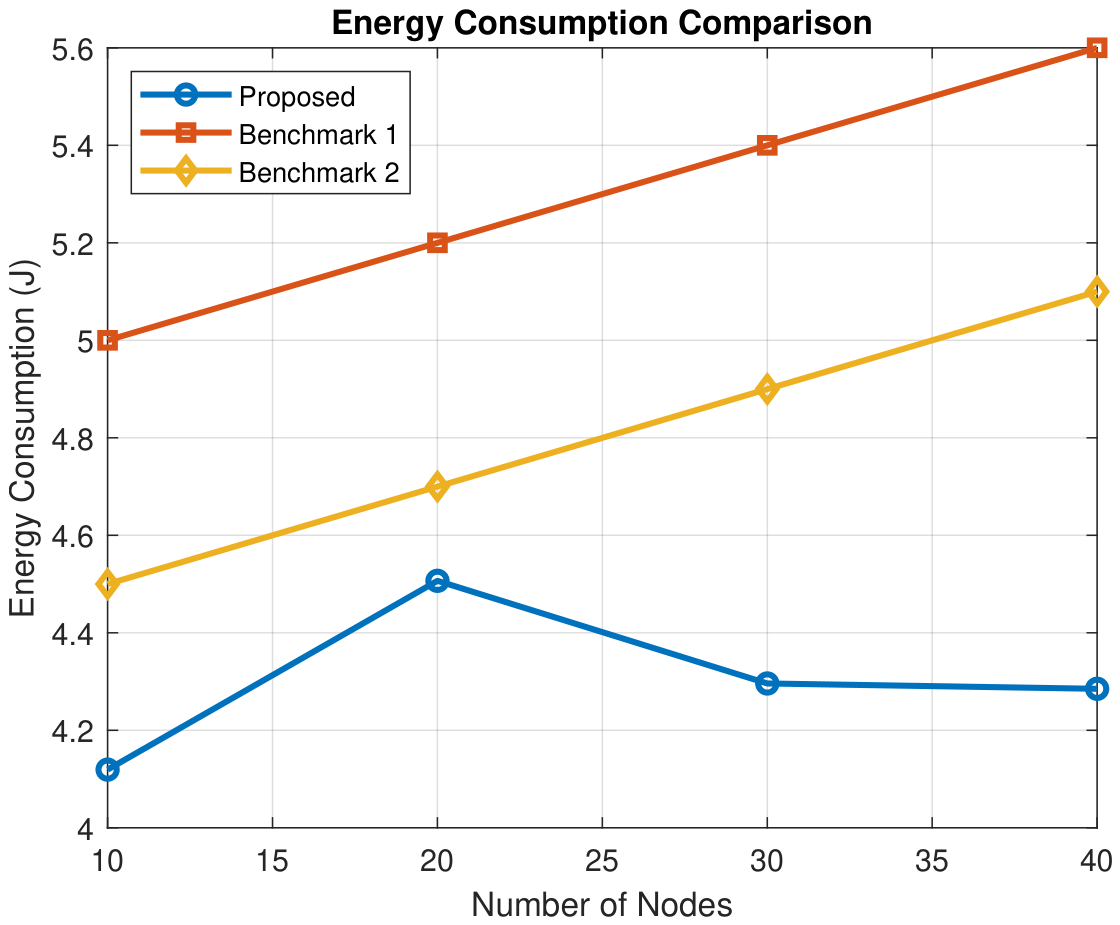
Figure 9.
Trajectory and path-fitness comparison across different network sizes. The reported cost follows the GA fitness definition, which combines flight time, cumulative collection-time AoI, and trajectory-smoothness penalty under the shared benchmark environment.
Figure 9.
Trajectory and path-fitness comparison across different network sizes. The reported cost follows the GA fitness definition, which combines flight time, cumulative collection-time AoI, and trajectory-smoothness penalty under the shared benchmark environment.
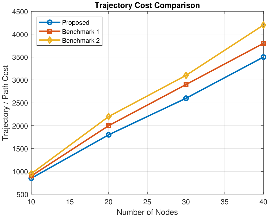
7.10. Overall Discussion
The experimental results show that the proposed framework provides a balanced and effective mission-level solution compared with both planning-oriented and MEC-oriented benchmark methods. Against the Modified GA planning baseline, the proposed framework achieved the same 100% sensing success rate and collision-free execution, while reducing average AoI from 183.74 s to 83.93 s, total collection time from 396.29 s to 168.91 s, and total energy consumption from 265.91 J to 244.50 J. These results demonstrate that GA-based task allocation and route sequencing alone are not sufficient for time-critical disaster-response sensing, especially when information freshness and execution efficiency are considered.
Against the Benchmark 2-adapted PPO–Greedy–SCA/CVX cooperative MEC baseline, the proposed framework also maintained complete sensing coverage with no dropped tasks, while achieving lower AoI, lower delay, lower processing delay, lower energy consumption, and lower system cost. Specifically, the proposed framework reduced average AoI from 126.84 s to 83.93 s, average delay from 40.49 s to 8.45 s, average processing delay from 40.07 s to 7.46 s, total energy consumption from 2119.53 J to 244.50 J, and system cost from 1399.15 to 21.31. Although the Benchmark 2-adapted baseline achieved slightly higher fairness and shorter computational runtime, it produced 24 inter-UAV collisions and 7 near misses, whereas the proposed framework achieved zero inter-UAV collisions and only two near misses.
The most important observation is that the proposed framework does not rely on a single dominant metric. Instead, it jointly considers sensing success, AoI, delay, processing delay, energy consumption, queue stability, and safety-aware execution. This balance is particularly important in disaster-response scenarios, where a method that is computationally efficient but unsafe, or fast but energy-intensive and stale in information delivery, is not operationally sufficient. The proposed framework therefore provides a more practical trade-off between information freshness, energy efficiency, computation control, and safe multi-UAV coordination.
Overall, the reported results support the central premise of this work: a layered spatial–temporal–safety decision framework is more suitable for realistic multi-UAV disaster monitoring than fragmented optimisation of route planning or computation management alone. By integrating 3D-TSPN sensing neighbourhoods, AoI-aware GA sequencing, RRT-Connect path feasibility checking, Lyapunov-based binary MEC offloading, queue-stability control, and multi-UAV safety monitoring, the proposed framework offers a more complete and operationally robust solution for disaster-response data collection in complex 3D environments.
Table 10.
Unified comparison between the proposed framework and recent benchmark methods.
| Metric | Proposed Framework | Benchmark 1: Modified GA Planning | Benchmark 2: Cooperative MEC Optimisation |
|---|---|---|---|
| Core optimisation scope | 3D-TSPN sensing coverage, AoI-aware GA sequencing, RRT-Connect path feasibility, Lyapunov-based binary MEC offloading, and safety monitoring. | Modified GA-based integrated multi-UAV task allocation and path planning with resource-related and simultaneous-arrival constraints. | Multi-UAV cooperative MEC optimisation using PPO-based trajectory planning, greedy association, SCA/CVX-based resource allocation, and cooperative task offloading. |
| Sensing coverage | Explicitly modelled using 3D sensing neighbourhoods around sensors. | Addressed indirectly as task/target assignment and visitation, but not modelled as sensing-neighbourhood coverage. | Not the primary focus. |
| Obstacle-aware 3D feasibility | Explicitly addressed using RRT-Connect and inflated obstacle models. | Limited in the disaster-response sense; the benchmark focuses on flyable planning and task execution rather than 3D obstacle-rich sensing environments. | Not the primary focus. |
| AoI awareness | Explicitly included in route sequencing and task completion evaluation. | Not explicitly addressed. | Not explicitly addressed. |
| Computation offloading | Binary local/MEC decision using Lyapunov-based temporal control. | Not addressed; the benchmark is planning-oriented. | Central component, including cooperative computation and inter-UAV task offloading. |
| Queue stability | Explicitly addressed through Lyapunov drift-plus-penalty control. | Not addressed. | Not explicitly addressed as Lyapunov queue stability; computation delay and resource allocation are optimised instead. |
| Mission / collection time | Reported from the proposed simulation output. | Reported or represented through planning-efficiency measures such as mission completion time and route cost. | Not reported as direct sensing mission collection time; the focus is computation task completion and system cost. |
| Average AoI | Reported from the proposed simulation output. | Not reported. | Not reported. |
| Average delay | Reported under spatial execution and binary offloading constraints. | Not reported in the same computation-processing form. | Reported as a computation-performance metric. |
| Energy consumption | Includes flight, local processing, and MEC transmission energy. | Represented mainly through distance/fuel-related planning constraints rather than detailed computation or communication energy. | Central to the energy–delay trade-off analysis. |
| Fairness | Evaluated under combined sensing, trajectory, and computation constraints. | Not a primary metric, although the maximum route-length term can indirectly reduce workload imbalance. | Strongly emphasised under cooperative MEC and load-balancing settings. |
| Scalability | Evaluated by increasing sensing demand, UAV workload, and environmental complexity. | Evaluated mainly through planning complexity, number of UAVs/targets, and mission completion behaviour. | Evaluated mainly through network size, task demand, available resources, and environmental dynamics. |
| Safety | Includes obstacle collision checking, inter-UAV monitoring, and buffer-zone analysis. | Limited or not reported in the same continuous 3D safety-monitoring form. | Not usually a primary metric. |
| Main strength | Balanced mission-level optimisation across sensing coverage, information freshness, computation control, and safety. | Strong integrated task allocation and route-planning capability using a modified GA. | Strong cooperative computation, trajectory planning, and resource allocation under MEC constraints. |
| Main limitation | Requires more comprehensive evaluation because spatial planning, temporal control, and safety monitoring interact within one framework. | Limited integration of AoI, MEC processing, queue stability, and continuous 3D safety monitoring. | Limited integration of obstacle-aware 3D route realisation, sensing-neighbourhood coverage, and information freshness. |
8. Conclusions and Future Work
This paper proposed a layered spatial–temporal optimisation framework for resilient multi-UAV disaster-response missions in complex three-dimensional and communication-constrained environments. The proposed architecture integrates 3D-TSPN sensing-neighbourhood coverage, AoI-aware GA-based route sequencing, RRT-Connect path feasibility checking, Lyapunov-based binary MEC offloading, and continuous-time multi-UAV safety monitoring within a single coordinated execution framework. By jointly considering sensing coverage, obstacle-aware path feasibility, AoI freshness, queue stability, computation delay, energy consumption, and safety, the framework addresses key limitations of fragmented UAV planning and computation-control approaches.
The experimental evaluation demonstrates that the proposed framework provides a balanced mission-level solution for UAV-assisted disaster data collection. The spatial layer improves coverage flexibility by allowing UAVs to collect data from sensing neighbourhoods rather than exact sensor coordinates, while the AoI-aware GA prioritises freshness during route sequencing. RRT-Connect supports obstacle-aware 3D path generation, and the Lyapunov-based temporal layer dynamically selects between local processing and full MEC offloading according to queue backlog, delay, energy, AoI, and wireless channel conditions. In addition, the safety monitoring layer supports concurrent multi-UAV operation through obstacle inflation, closest-approach checking, temporal desynchronisation, and collision-risk monitoring.
Overall, the results confirm the value of separating the framework into spatial, temporal, and safety layers while allowing these layers to interact through shared mission states. This structure improves interpretability, reduces unnecessary algorithmic complexity, and provides a practical foundation for time-critical UAV-assisted disaster monitoring and data collection. Unlike overly complex hybrid designs, the proposed framework maintains a clear role for each component: 3D-TSPN provides coverage flexibility, AoI-aware GA determines freshness-aware route ordering, RRT-Connect verifies 3D path feasibility, Lyapunov control manages binary computation decisions, and safety monitoring supports collision-free multi-UAV execution.
The current study has several limitations. First, the evaluation is simulation-based and has not yet been validated using physical UAV hardware. Second, the environment contains static obstacle structures and a single MEC node, whereas real disaster environments may include dynamic obstacles, multiple edge nodes, and time-varying sensing priorities. Third, the propulsion, communication, and computation energy models are intentionally simplified to support a clear comparative evaluation. Finally, the present experiments focus on a four-UAV scenario. Larger-scale swarm evaluation is required to investigate scalability under more demanding operational conditions.
Future work will focus on extending the framework to larger UAV swarms, evaluating additional disaster scenarios with dynamic obstacles and moving sensing targets, incorporating learning-based adaptation for uncertain wireless and mobility conditions, and validating the complete pipeline through hardware-in-the-loop simulations and real-world UAV experiments. Further work will also investigate more advanced cooperation strategies between UAVs and edge nodes while preserving the simplified layered structure introduced in this study.
Author Contributions
Conceptualization, R.A. and S.G.; methodology, R.A. and S.G.; software, R.A.; validation, R.A., S.G. and M.N.K.; formal analysis, R.A.; investigation, R.A.; resources, S.G.; writing—original draft preparation, R.A.; writing—review and editing, S.G. and M.N.K.; supervision, S.G. and M.N.K. All authors have read and agreed to the published version of the manuscript.
Funding
This research received no external funding.
Institutional Review Board Statement
Not applicable.
Informed Consent Statement
Not applicable.
Data Availability Statement
The data supporting the findings of this study are available from the corresponding author upon reasonable request.
Conflicts of Interest
The authors declare no conflicts of interest.
References
- Bushnaq, O. M.; Mishra, D.; Natalizio, E.; Akyildiz, I. F. Unmanned Aerial Vehicles (UAVs) for Disaster Management. In Nanotechnology-Based Smart Remote Sensing Networks for Disaster Prevention; Denizli, A., et al., Eds.; Elsevier, 2022; pp. 159–188. [Google Scholar] [CrossRef]
- Chandran, I.; Vipin, K. Multi-UAV Networks for Disaster Monitoring: Challenges and Opportunities from a Network Perspective. Drone Syst. Appl. 2024, 12, 1–28. [Google Scholar] [CrossRef]
- Kumbhar, A.; Koohifar, F.; Güvenç, I.; Mueller, B. A Survey on Legacy and Emerging Technologies for Public Safety Communications. IEEE Commun. Surv. Tutor. 2017, 19(1), 97–124. [Google Scholar] [CrossRef]
- Mozaffari, M.; Saad, W.; Bennis, M.; Nam, Y.-H.; Debbah, M. A Tutorial on UAVs for Wireless Networks: Applications, Challenges, and Open Problems. IEEE Commun. Surv. Tutor. 2019, 21(3), 2334–2360. [Google Scholar] [CrossRef]
- Sharma, A.; Vanjani, P.; Paliwal, N.; Basnayaka, C. M. W.; Jayakody, D. N. K.; Wang, H.-C.; Muthuchidambaranathan, P. Communication and Networking Technologies for UAVs: A Survey. J. Netw. Comput. Appl. 2020, 168, 102739. [Google Scholar] [CrossRef]
- Wei, Z.; Zhu, M.; Zhang, N.; Wang, L.; Zou, Y.; Meng, Z.; Wu, H.; Feng, Z. UAV-Assisted Data Collection for Internet of Things: A Survey. IEEE Internet Things J. 2022, 9(17), 15460–15483. [Google Scholar] [CrossRef]
- Cao, H.; Liu, Y.; Yue, X.; Zhu, W. Cloud-Assisted UAV Data Collection for Multiple Emerging Events in Distributed WSNs. Sensors 2017, 17(8), 1818. [Google Scholar] [CrossRef] [PubMed]
- Xu, J.; Ota, K.; Dong, M. Big data on the fly: UAV-mounted mobile edge computing for disaster management. IEEE Trans. Netw. Sci. Eng. 2020, 7(4), 2620–2630. [Google Scholar] [CrossRef]
- Shi, W.; Cao, J.; Zhang, Q.; Li, Y.; Xu, L. Edge Computing: Vision and Challenges. IEEE Internet Things J. 2016, 3(5), 637–646. [Google Scholar] [CrossRef]
- Hentati, A. I.; Fourati, L. C. Comprehensive Survey of UAVs Communication Networks. Comput. Stand. Interfaces 2020, 72, 103451. [Google Scholar] [CrossRef]
- Chowdhury, M. Z.; Shahjalal, M.; Ahmed, S.; Jang, Y. M. 6G Wireless Communication Systems: Applications, Requirements, Technologies, Challenges, and Research Directions. IEEE Open J. Commun. Soc. 2020, 1, 957–975. [Google Scholar] [CrossRef]
- Neely, M. J. Stochastic Network Optimization with Application to Communication and Queueing Systems. In Synthesis Lectures on Communication Networks; Morgan & Claypool Publishers, 2010. [Google Scholar] [CrossRef]
- LaValle, S. M. Rapidly-Exploring Random Trees: A New Tool for Path Planning. Department of Computer Science, Iowa State University, Ames, IA, USA, TR 98-11, 1998. Available online: https://msl.cs.illinois.edu/~lavalle/papers/Lav98c.pdf (accessed on 25 June 2026).
- Kuffner, J. J.; LaValle, S. M. RRT-Connect: An Efficient Approach to Single-Query Path Planning. In Proceedings of the IEEE International Conference on Robotics and Automation, 2000; pp. 995–1001. [Google Scholar] [CrossRef]
- Dorigo, M.; Birattari, M.; Stützle, T. Ant Colony Optimization. IEEE Comput. Intell. Mag. 2006, 1(4), 28–39. [Google Scholar] [CrossRef]
- Kennedy, J.; Eberhart, R. Particle Swarm Optimization. In Proceedings of the IEEE International Conference on Neural Networks, 1995; pp. 1942–1948. [Google Scholar] [CrossRef]
- Kaul, S.; Yates, R.; Gruteser, M. Real-Time Status: How Often Should One Update? In IEEE INFOCOM 2012; 2012; pp. 2731–2735. [Google Scholar] [CrossRef]
- Mao, Y.; You, C.; Zhang, J.; Huang, K.; Letaief, K. B. A Survey on Mobile Edge Computing: The Communication Perspective. IEEE Commun. Surv. Tutor. 2017, 19(4), 2322–2358. [Google Scholar] [CrossRef]
- Karaman, S.; Frazzoli, E. Sampling-Based Algorithms for Optimal Motion Planning. Int. J. Robot. Res. 2011, 30(7), 846–894. [Google Scholar] [CrossRef]
- Holland, J. H. Adaptation in Natural and Artificial Systems: An Introductory Analysis with Applications to Biology, Control, and Artificial Intelligence; University of Michigan Press: Ann Arbor, MI, USA, 1975. [Google Scholar]
- Goldberg, D. E. Genetic Algorithms in Search, Optimization and Machine Learning; Addison-Wesley: Reading, MA, USA, 1989. [Google Scholar]
- Kennedy, J.; Eberhart, R. Particle Swarm Optimization. In Proceedings of the IEEE International Conference on Neural Networks, 1995; pp. 1942–1948. [Google Scholar] [CrossRef]
- Poudel, S.; Arafat, M. Y.; Moh, S. Bio-Inspired Optimization-Based Path Planning Algorithms in Unmanned Aerial Vehicles: A Survey. Sensors 2023, 23(6), 3051. [Google Scholar] [CrossRef] [PubMed]
- Baek, J.; Han, S. I.; Han, Y. Optimal UAV Route in Wireless Charging Sensor Networks. IEEE Internet Things J. 2020, 7(2), 1327–1335. [Google Scholar] [CrossRef]
- Jia, Z.; Qin, X.; Wang, Z.; Liu, B. Age-Based Path Planning and Data Acquisition in UAV-Assisted IoT Networks. In Proceedings of the IEEE International Conference on Communications Workshops, 2019; pp. 1–6. [Google Scholar] [CrossRef]
- Zhan, C.; Zeng, Y. Completion Time Minimization for Multi-UAV-Enabled Data Collection. IEEE Trans. Wirel. Commun. 2019, 18(10), 4859–4872. [Google Scholar] [CrossRef]
- Zhan, C.; Huang, R. Energy Minimization for Data Collection in Wireless Sensor Networks with UAV. In Proceedings of the 2019 IEEE Global Communications Conference (GLOBECOM), 2019; pp. 1–6. [Google Scholar] [CrossRef]
- Luo, C.; Satpute, M. N.; Li, D.; Wang, Y.; Chen, W.; Wu, W. Fine-Grained Trajectory Optimization of Multiple UAVs for Efficient Data Gathering from WSNs. IEEE/ACM Trans. Netw. 2021, 29(1), 162–175. [Google Scholar] [CrossRef]
- Abd-Elmagid, M. A.; Ferdowsi, A.; Dhillon, H. S.; Saad, W. Deep Reinforcement Learning for Minimizing Age of Information in UAV-Assisted Networks. arXiv. 2019. Available online: https://arxiv.org/abs/1905.02993 (accessed on 25 June 2026).
- Eldeeb, E.; Perez, D. E.; Michel de Souza Sant’Ana, J.; Shehab, M.; Mahmood, N. H.; Alves, H.; Latva-Aho, M. A Learning-Based Trajectory Planning of Multiple UAVs for AoI Minimization in IoT Networks. In Proceedings of the 2022 Joint European Conference on Networks and Communications & 6G Summit (EuCNC/6G Summit), 2022; pp. 172–177. [Google Scholar] [CrossRef]
- Tong, P.; Liu, J.; Wang, X.; Bai, B.; Dai, H. UAV-Enabled Age-Optimal Data Collection in Wireless Sensor Networks. IEEE Trans. Commun. 2019, 67(11), 7778–7791. [Google Scholar] [CrossRef]
- Mao, Y.; You, C.; Zhang, J.; Huang, K.; Letaief, K. B. A Survey on Mobile Edge Computing: The Communication Perspective. IEEE Commun. Surv. Tutor. 2017, 19(4), 2322–2358. [Google Scholar] [CrossRef]
- Xu, J.; Ota, K.; Dong, M. Big Data on the Fly: UAV-Mounted Mobile Edge Computing for Disaster Management. IEEE Trans. Netw. Sci. Eng. 2020, 7(4), 2620–2630. [Google Scholar] [CrossRef]
- Messaoudi, K.; Oubbati, O. S.; Rachedi, A.; Lakas, A.; Bendouma, T.; Chaib, N. A Survey of UAV-Based Data Collection: Challenges, Solutions and Future Perspectives. J. Netw. Comput. Appl. 2023, 216, 103670. [Google Scholar] [CrossRef]
- Ning, Z.; Yang, Y.; Wang, X.; Guo, L.; Gao, X.; Guo, S.; Wang, G. Dynamic Computation Offloading and Server Deployment for UAV-Enabled Multi-Access Edge Computing. IEEE Trans. Mob. Comput. 2023, 22(5), 2628–2644. [Google Scholar] [CrossRef]
- Meng, K.; He, X.; Wu, Q.; Li, D. Multi-UAV Collaborative Sensing and Communication: Joint Task Allocation and Power Optimization. IEEE Trans. Wirel. Commun. 2023, 22(6), 4232–4246. [Google Scholar] [CrossRef]
- Sharon, G.; Stern, R.; Felner, A.; Sturtevant, N. R. Conflict-Based Search for Optimal Multi-Agent Pathfinding. Artif. Intell. 2015, 219, 40–66. [Google Scholar] [CrossRef]
- Phillips, M.; Likhachev, M. SIPP: Safe Interval Path Planning for Dynamic Environments. In Proceedings of the IEEE International Conference on Robotics and Automation, 2011; pp. 5628–5635. [Google Scholar] [CrossRef]
- Stern, R.; Sturtevant, N. R.; Felner, A.; Koenig, S.; Ma, H.; Walker, T.; Li, J.; Atzmon, D.; Cohen, L.; Kumar, T. K. S.; Boyarski, E.; Barták, R. Multi-Agent Pathfinding: Definitions, Variants, and Benchmarks. In Proceedings of the 12th International Symposium on Combinatorial Search, 2019; pp. 151–158. [Google Scholar] [CrossRef]
- Alfattani, S.; Jaafar, W.; Yanikomeroglu, H.; Yongacoglu, A. Multi-UAV Data Collection Framework for Wireless Sensor Networks. In Proceedings of the 2019 IEEE Global Communications Conference (GLOBECOM), Waikoloa, HI, USA, 2019; pp. 1–6. [Google Scholar] [CrossRef]
- Li, L.; Zhou, S.; Wang, Z. A Novel Multi-UAV Patrol Path Planning Method Based on Evolutionary Multi-Objective Optimization. In Proceedings of the 2022 4th International Conference on Intelligent Information Processing (IIP), Guangzhou, China, 2022; pp. 332–335. [Google Scholar] [CrossRef]
- Peng, C.; Wang, X.; Huang, L.; Chen, D. A Decomposition-Based Constrained Multi-Objective Evolutionary Algorithm with a Local Infeasibility Utilization Mechanism for UAV Path Planning. Appl. Soft Comput. 2022, 116, 108495. [Google Scholar] [CrossRef]
- Ratliff, N.; Zucker, M.; Bagnell, J. A.; Srinivasa, S. CHOMP: Gradient Optimization Techniques for Efficient Motion Planning. In Proceedings of the 2009 IEEE International Conference on Robotics and Automation, Kobe, Japan, 2009; pp. 489–494. [Google Scholar] [CrossRef]
- Kalakrishnan, M.; Chitta, S.; Theodorou, E.; Pastor, P.; Schaal, S. STOMP: Stochastic Trajectory Optimization for Motion Planning. In Proceedings of the 2011 IEEE International Conference on Robotics and Automation, 2011; pp. 4569–4574. [Google Scholar] [CrossRef]
- Mellinger, D.; Kumar, V. Minimum Snap Trajectory Generation and Control for Quadrotors. In Proceedings of the 2011 IEEE International Conference on Robotics and Automation, 2011; pp. 2520–2525. [Google Scholar] [CrossRef]
- Yin, S.; Zhao, S.; Zhao, Y.; Yu, F. R. Intelligent Trajectory Design in UAV-Aided Communications with Reinforcement Learning. IEEE Trans. Veh. Technol. 2019, 68(8), 8227–8231. [Google Scholar] [CrossRef]
- Saleem, Y.; Rehmani, M. H.; Zeadally, S. Integration of Cognitive Radio Technology with Unmanned Aerial Vehicles: Issues, Opportunities, and Future Research Challenges. J. Netw. Comput. Appl. 2015, 50, 15–31. [Google Scholar] [CrossRef]
- Li, J.; Sun, G.; Duan, L.; Wu, Q. Multi-Objective Optimization for UAV Swarm-Assisted IoT with Virtual Antenna Arrays. IEEE Trans. Mob. Comput. 2024, 23(5), 4890–4907. [Google Scholar] [CrossRef]
- van den Berg, J.; Guy, S. J.; Lin, M.; Manocha, D. Reciprocal n-Body Collision Avoidance. In Robotics Research; Springer: Berlin, Heidelberg, 2011; pp. 3–19. [Google Scholar] [CrossRef]
- Yan, F.; Chu, J.; Hu, J.; Zhu, X. Cooperative task allocation with simultaneous arrival and resource constraint for multi-UAV using a genetic algorithm. Expert Syst. With Appl. 2024, 245, 123023. [Google Scholar] [CrossRef]
- Xu, W.; Zhang, T.; Mu, X.; Liu, Y.; Wang, Y. Trajectory Planning and Resource Allocation for Multi-UAV Cooperative Computation. IEEE Trans. Commun. 2024, 72(7), 4305–4318. [Google Scholar] [CrossRef]
Figure 1.
Lyapunov-based binary offloading layer for temporal processing decisions.
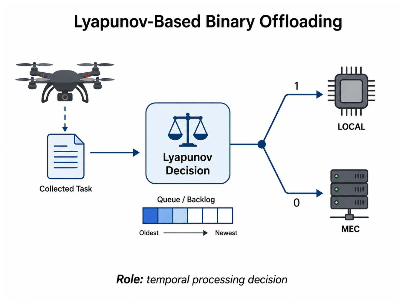
Figure 3.
Flowchart of the proposed multi-UAV optimisation process.
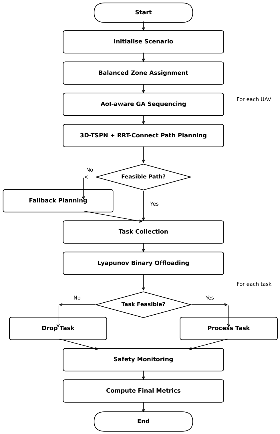
Figure 4.
Illustration of 3D-TSPN sensing neighbourhood-based data collection compared with traditional exact-point sensor visiting.
Figure 4.
Illustration of 3D-TSPN sensing neighbourhood-based data collection compared with traditional exact-point sensor visiting.
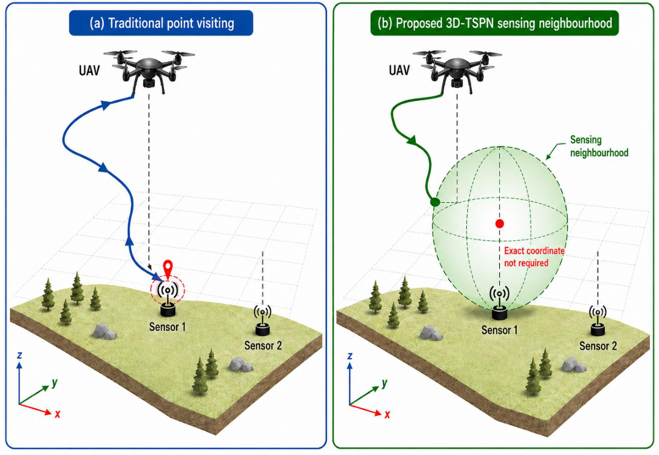
Figure 5.
AoI-aware GA routing layer for spatial route planning.
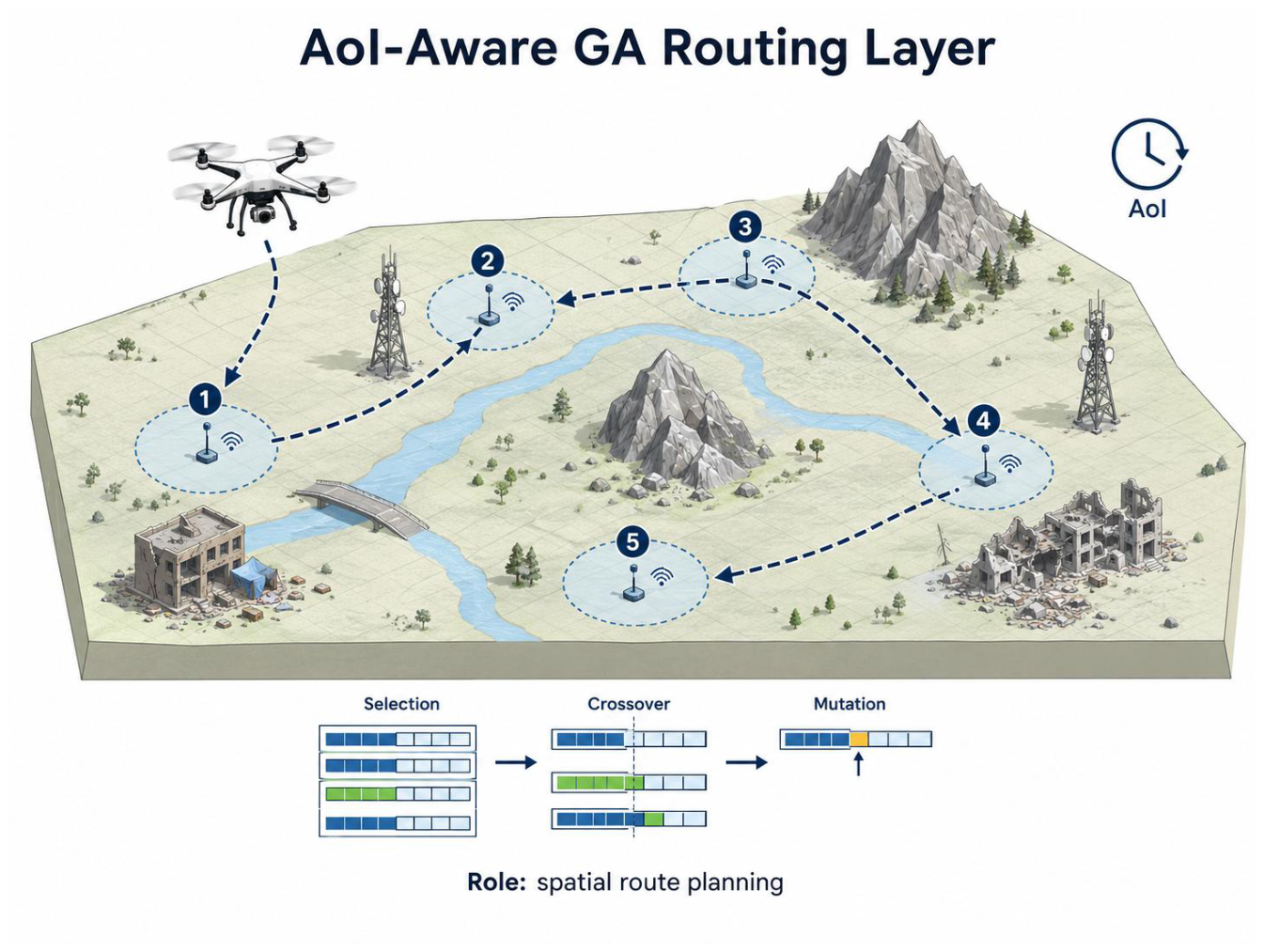
Figure 6.
Normalised performance comparison with the Modified GA baseline.
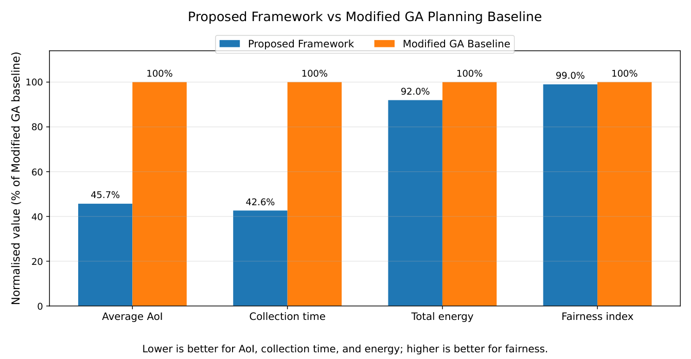
Figure 7.
Normalised performance comparison between the proposed framework and the Benchmark 2-adapted PPO–Greedy–SCA/CVX cooperative MEC baseline. The Benchmark 2 baseline is normalised to 100% for each metric.
Figure 7.
Normalised performance comparison between the proposed framework and the Benchmark 2-adapted PPO–Greedy–SCA/CVX cooperative MEC baseline. The Benchmark 2 baseline is normalised to 100% for each metric.
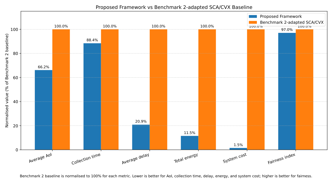
Table 1.
Simulation Parameters and Default Values.
| Parameter | Value |
|---|---|
| Disaster region size | |
| Number of sensors N | 20 |
| Number of UAVs U | 4 |
| Sensor sensing radius | |
| Data collection time | |
| UAV speed | |
| Battery capacity | |
| Safety margin | |
| Minimum UAV separation | |
| Collision avoidance radius | |
| Slowdown factor | |
| Number of obstacle towers | 3 |
| MEC node position | |
| Data size per sensor | |
| Carrier frequency | |
| Dynamic bandwidth range | – |
| Bandwidth jitter | |
| Link outage probability | |
| Path-loss exponent | |
| Minimum transmit power | |
| Maximum transmit power | |
| UAV CPU capacity | |
| MEC CPU capacity | |
| CPU cycles per bit | |
| Maximum task deadline | |
| GA population size | 60 |
| GA maximum generations | 120 |
| GA time limit per UAV | |
| GA crossover probability | |
| Base mutation rate | |
| Elite rate | |
| RRT step size | |
| RRT maximum nodes | 400 |
| RRT goal bias probability | |
| Lyapunov control parameter V | |
| UAV flight or hovering power | |
| UAV computation power | |
| Reference channel gain | |
| Noise power spectral density | |
| Instantaneous noise power | – |
| Instantaneous noise power in dBm | to |
| Base interference power | |
| Interference burst probability | |
| Interference burst multiplier | 30 |
| Simulation time-step duration | |
| GA weights | |
| GA feasibility handling | Hard rejection, |
| Lyapunov weights | |
| Number of independent simulation runs | 1 |
| Random-seed approach | [l]Fixed simulation seed 42; |
| clustering seed 0 | |
| UAV start-time offsets |
Table 2.
Comparative Performance Across Planning Configurations.
| Method | UAVs | Success | Avg. AoI (s) | Energy (J) | Time (s) | Collisions |
|---|---|---|---|---|---|---|
| Proposed Full Framework | 4 | 100.0% | 74.24 | 266.96 | 210.66 | 0 |
| Nearest Neighbour Baseline | 4 | 85.0% | 145.76 | 325.81 | 293.80 | 17 |
| Single-UAV Baseline | 1 | 100.0% | 151.56 | 189.09 | 460.92 | 0 |
Table 3.
Single-UAV versus Proposed Multi-UAV Framework.
| Metric | Single | 4 UAVs | Change |
|---|---|---|---|
| Success rate | 100.0% | 100.0% | No change |
| Sensors collected | 20 | 20 | No change |
| Average AoI (s) | 151.56 | 74.24 | 51.0% red. |
| Energy (J) | 189.09 | 266.96 | 41.2% inc. |
| Collection time (s) | 460.92 | 210.66 | 54.3% red. |
| Obstacle collisions | 0 | 0 | No change |
| Inter-UAV collisions | N/A | 0 | Collision-free |
Table 4.
Binary Processing Decisions and Final Queue Backlogs.
| Metric | Value |
|---|---|
| LOCAL decisions | 19 |
| MEC offloading decisions | 1 |
| Dropped tasks | 0 |
| Final queue backlog, UAV 1 | 4.50 |
| Final queue backlog, UAV 2 | 5.33 |
| Final queue backlog, UAV 3 | 4.49 |
| Final queue backlog, UAV 4 | 7.12 |
Table 6.
Safety and Collision Monitoring Results.
| Safety Metric | Value |
|---|---|
| Real obstacle collisions | 0 |
| Inter-UAV collisions | 0 |
| Near misses | 0 |
| Buffer-zone intrusions | 0 |
Table 7.
System-Level Robustness Metrics.
| Metric | Observed Value |
|---|---|
| Coverage success rate | 100.0% |
| Average AoI | 74.24 s |
| Total collection time | 210.66 s |
| Total energy consumption | 266.96 J |
| LOCAL decisions | 19 |
| MEC offloading decisions | 1 |
| Dropped tasks | 0 |
| Final queue backlog | 4.49–7.12 tasks |
| Real obstacle collisions | 0 |
| Inter-UAV collisions | 0 |
| Near misses | 0 |
| Buffer-zone intrusions | 0 |
Table 8.
Comparison with the Modified GA Planning Baseline Inspired by Benchmark 1.
| Metric | Proposed Framework | Modified GA Baseline | Better Result |
|---|---|---|---|
| Success rate | 100.0% | 100.0% | Equal |
| Sensors collected | 20/20 | 20/20 | Equal |
| Average AoI (s) | 83.93 | 183.74 | Proposed |
| Total collection time (s) | 168.91 | 396.29 | Proposed |
| Total energy consumption (J) | 244.50 | 265.91 | Proposed |
| Average energy per collected sensor (J) | 12.23 | 13.30 | Proposed |
| Obstacle collisions | 0 | 0 | Equal |
| Inter-UAV collisions | 0 | 0 | Equal |
| Buffer-zone intrusions | 0 | 0 | Equal |
| Dropped tasks | 0 | 0 | Equal |
| Fairness index | 0.9705 | 0.9804 | Modified GA |
Table 9.
Comparison Between the Proposed Framework and the Benchmark 2-Adapted PPO–Greedy–SCA/CVX Cooperative MEC Baseline.
Table 9.
Comparison Between the Proposed Framework and the Benchmark 2-Adapted PPO–Greedy–SCA/CVX Cooperative MEC Baseline.
| Metric | Proposed Framework | Benchmark 2-Adapted SCA/CVX | Better Result |
|---|---|---|---|
| Success rate | 100.0% | 100.0% | Equal |
| Sensors collected | 20/20 | 20/20 | Equal |
| Total collection time (s) | 168.91 | 191.05 | Proposed |
| Average AoI (s) | 83.93 | 126.84 | Proposed |
| Average delay per sensor (s) | 8.45 | 40.49 | Proposed |
| Average processing delay (s) | 7.46 | 40.07 | Proposed |
| Total energy consumption (J) | 244.50 | 2119.53 | Proposed |
| Average energy per task (J) | 3.93 | 105.98 | Proposed |
| System cost | 21.31 | 1399.15 | Proposed |
| Jain fairness index | 0.9705 | 1.0000 | Benchmark 2 |
| Weighted fairness index | 0.9613 | 0.9997 | Benchmark 2 |
| Obstacle collisions | 0 | 0 | Equal |
| Inter-UAV collisions | 0 | 24 | Proposed |
| Near misses | 2 | 7 | Proposed |
| Buffer-zone intrusions | 0 | 0 | Equal |
| Dropped tasks | 0 | 0 | Equal |
| Runtime (s) | 37.53 | 1.53 | Benchmark 2 |
| CVX solver used | N/A | Yes | N/A |
Disclaimer/Publisher’s Note: The statements, opinions and data contained in all publications are solely those of the individual author(s) and contributor(s) and not of MDPI and/or the editor(s). MDPI and/or the editor(s) disclaim responsibility for any injury to people or property resulting from any ideas, methods, instructions or products referred to in the content. |
© 2026 by the authors. Licensee MDPI, Basel, Switzerland. This article is an open access article distributed under the terms and conditions of the Creative Commons Attribution (CC BY) license (http://creativecommons.org/licenses/by/4.0/).
Copyright: This open access article is published under a Creative Commons CC BY 4.0 license, which permit the free download, distribution, and reuse, provided that the author and preprint are cited in any reuse.


