
Submitted:
14 July 2026
Posted:
15 July 2026
You are already at the latest version
Abstract
Microwave photonic (MWP) Fano filters, featuring asymmetric filter shapes that enable steep spectral transitions, are attractive for high-bandwidth microwave signal processing such as frequency discrimination. However, achieving both steep spectral transitions and a high degree of reconfigurability remains challenging for conventional methods relying on direct mapping of Fano resonances generated by optical filters. Here, we propose and experimentally demonstrate a new way for realizing MWP Fano filters based on a microcomb-driven transversal filter system. Leveraging the large number of comb lines provided by microcombs as discrete taps, the transversal filter system can synthesize filter response that closely resembles Fano resonances, yielding high roll-off rates and slope rates up to ~33.8 dB / GHz and ~25.7 dB / GHz in our experiments, respectively. In addition, by simply programming the tap coefficients without changing any hardware, highly reconfigurable filter response can be realized. We experimentally demonstrate independent tuning of all three Fano characteristic parameters, including the asymmetry factor, resonance linewidth, and center frequency. These results verify the effectiveness of our approach for implementing highly reconfigurable MWP Fano filters with steep spectral transitions, offering strong versatility for meeting diverse requirements in practical applications.
Keywords:
microwave photonics
; optical microcombs
; Fano resonance
I. Introduction
Microwave photonic (MWP) filters, which perform filtering functions in the microwave (MW) frequency band using photonic technologies, offer attractive advantages of broad operation bandwidths that overcomes the intrinsic bandwidth bottleneck of electronic devices, low loss that improves signal-to-noise ratios, and strong immunity to electromagnetic interference [1,2,3,4]. Nowadays, MWP filters have found wide applications for high-bandwidth MW signal processing in modern communication, radar, and sensing systems [5,6,7,8]. As a fundamental class of MWP filters, MWP Fano filters, featuring asymmetric filter shapes that enable steep spectral transitions, are particularly attractive for high-sensitivity frequency discrimination and instantaneous frequency measurement [9,10,11].
Conventional MWP Fano filters are typically realized by using a single optical carrier to map the response of Fano resonances generated by optical resonators into the MW domain [9,10,11]. In these filters, Fano resonances are generated by engineering the interference between a discrete localized state and a continuum state [12,13,14], and high quality (Q) factors of the optical resonators are needed to enable steep spectral transitions, thereby enhancing the sensitivity for frequency discrimination. However, the high Q factors also lead to increased sensitivity to resonance drift and fabrication tolerances, thus imposing stringent requirements on resonance alignment and thermal stabilization for long-term operation [15]. In addition, these filters usually lack reconfigurability, although minor adjustments can be made by introducing PN junctions [16,17] or thermo-optic heaters [18,19]. In particular, the characteristic parameters of Fano filters, including the asymmetry factor, resonance linewidth, and center frequency, are determined by multiple structural parameters of the optical resonators, making it challenging to tune one parameter independently without affecting the others. The above limitations collectively make it challenging to realize MWP Fano filters that simultaneously offer steep spectral transitions and a high degree of reconfigurability.
In this work, we propose and experimentally demonstrate MWP Fano filters based on a microcomb-driven transversal filter system, enabling both steep spectral transitions and a high degree of reconfigurability. By using the large number of comb lines provided by optical microcombs as discrete taps, the transversal filter system can synthesize filter response that closely resembles Fano resonances through coherent combination of delayed and weighted taps. Experimental results show that high roll-off rates and slope rates up to ~33.8 dB / GHz and ~25.7 dB / GHz are achieved, respectively. Moreover, we experimentally demonstrate highly reconfigurable filter response by simply programming the tap coefficients without changing any hardware, achieving independent tuning of all three Fano characteristic parameters including the asymmetry factor, resonance linewidth, and center frequency. These results highlight the strong potential of our approach for implementing highly reconfigurable MWP Fano filters with steep spectral transitions, which are capable of addressing diverse requirements in practical applications.
II. Operation Principle
In this work, we investigate Fano filters exhibiting asymmetric spectral lineshapes, which were first elucidated by Fano through the well-known Fano formula as follows [20]
where q is the asymmetry factor and ε is the scale of reduced energy. In Eq. (1), the minimum transmission reaches 0 when ε = -q. In spectral filter applications, ε can be further defined as
where ω is the angular frequency, ωc is the center angular frequency, and Γ is the resonance linewidth. By substituting ω = 2πf, ωc = 2πfc and Γf = Γ / (2π) into Eq. (2), and then substituting Eq. (2) into Eq (1), the transfer function for MW Fano filters investigated in this work can be expressed as
where f, fc, and Гf are the corresponding MW frequency, center frequency, and resonance linewidth, respectively.
In Figure 1, we plot the spectral amplitude response of Fano filters based on Eq. (3). Figure 1(a) illustrates the roles of three characteristic parameters, namely q, Γf, and fc, in determining the spectral lineshape of the Fano filter. Here, points A and B mark the maximum and minimum transmission at frequencies of fA and fB, respectively. Point C corresponds to the center frequency of fc. As can be seen, the product of qΓf jointly determines the frequency offset between points B and C, which can be expressed as
fB - fc = qΓf
To better illustrate the relationship in Eq. (4), Figure 1(b), (c), and (d) compare the amplitude response of Fano filters with various q, Γf, and fc, respectively. In each figure, all parameters other than the one being varied are kept constant. Figure 1(b) shows the results for q = -1 and q = -4 at fixed Γf = Γ1 and fc = f1. At q = -1, the response spectrum exhibits an odd-symmetric profile, in which the transmission at the center frequency fc equals 0.5 (i.e., -3 dB). According to Eq. (4), it can also be obtained that fB - f1 = Γ1. At q = -4, the response spectrum becomes asymmetric. Point B shifts to point B’ at a higher frequency of fB’, satisfying fB’ - f1 = 4Γ1 according to Eq. (4). In addition, the transmission at fc increases and no longer equals 0.5, which is also governed by the relationship in Eq. (4). Figure 1(c) shows the response spectra for Γf = Γ1 and Γf = 2Γ1 at fixed q = -1 and fc = f1. As Γf increases from Γ1 to 2Γ1, the response spectrum remains odd-symmetric, and point B shifts to point B’ at a higher frequency of fB’. The former indicates a preserved filter symmetry, and the latter signifies an increased filtering bandwidth. Figure 1(d) shows the response spectra for fc = f1 and fc = f2 at fixed q = -1 and Γf = Γ1. The filter shape and bandwidth are identical in both cases, differing only in the center frequency. This reflects the fact that variation in fc does not alter the filter shape and bandwidth, forming the basis for implementing Fano filters with tunable center frequencies.
In practical applications, another two parameters ‒ the slope rate (SR) and the roll-off rate (ROR), are widely used to quantitatively compare the performance of Fano filters [9,12,21]. The SR is defined as [22]
where ER is the extinction ratio, i.e., the attenuation from transmission peak to notch, typically expressed in units of dB. The terms fP and fN are the frequencies corresponding to the transmission peak and notch, respectively. The ROR is defined as [4]
where AT is the attenuation from the -3 dB transmission point in the passband to a point corresponding to the reference level in the stopband. The terms f T and fR are the frequencies corresponding to these two points.
Figure 1(e) and 1(f) illustrate the definitions of SR and ROR in Eqs. (5) and (6), respectively. For both SR and ROR, higher values indicate steeper transitions and sharper roll-off in the filter response, which is desirable for practical Fano filter applications [9,11,23]. The SR is more commonly used for optical resonators with Fano resonances [12,13,14], whereas the ROR is typically used in the context of MW filters.
To realize the Fano filters shown in Figure 1, we employ a transversal filter system widely used for MW signal processing [24,25,26,27,28,29,30]. Figure 2(a) illustrates the operation principle of a MW transversal filter system. As the input MW signal propagates through the system, a cascade of delay elements introduces time delays between adjacent signal replicas, with each delay element providing a time delay of Δt. The delayed signal replica in each channel is weighted according to the designed tap coefficient (i.e., a0, a1, …, aM - 1), after which the delayed and weighted signal replicas from different channels are summed to produce the final output.
Figure 2(b) illustrates a transversal filter system implemented based on the MWP technology. Optical microcombs generated by a compact integrated MRR is employed as a multiwavelength source for the transversal filter system. Replicas of the input MW signal are generated by modulating it onto optical carriers at different wavelength channels. The delay between adjacent wavelength channels is provided by the dispersion of a spool of single-mode fiber (SMF), and the tap coefficient in each channel is assigned using a programmable optical spectral shaper (OSS). Finally, the delayed and weighted signal replicas are summed upon photodetection to generate a MW signal as the system output.
The output MW signal s(t) from the MWP transversal filter system in Figure 2(b) can be expressed as
where M is the total number of tap coefficient, an (n = 0, 1, 2, …, M - 1) is the tap coefficient of the nth tap, Δt is the delay time between adjacent taps and f(t) denoting the input MW signal. The temporal impulse response h(t) in Eq. (7) can be given by
where δ(t) is the unit impulse function. By applying the Fourier transform to Eq. (8), the spectral transfer function of the MWP transversal filter system can be written as
Eq. (9) represents a typical transfer function for the transversal filter systems [31], which exhibits finite impulse response (FIR), and diverse filtering functions can be realized by designing the corresponding tap coefficients an (n = 0, 1, 2, …, M - 1). This provides the basis for implementing Fano filters shown in Figure 1, enabling reconfigurable Fano filters with different asymmetry factor q, resonance linewidth Гf, or center frequencies fc to be realized simply through programing the tap coefficients an (n = 0, 1, 2, …, M - 1).
It is also worth noting that due to the FIR nature of transversal filter systems, deviations arise between the ideal filter response and that realized based on the transfer function in Eq. (9) for target filters with infinite impulse response (IIR), including Fano filters investigated in this work. These deviations can also degrade the SR and ROR of Fano filters realized based on the MWP transversal filter system. However, these deviations decrease as the tap number M increases and becomes negligible when M is sufficiently large. Therefore, a large number of wavelength channels are required in practical MWP transversal filter systems to minimize these deviations and increase the SR and ROR performance. For brevity, the filters realized based on Eq. (9) are referred to as MWP Fano filters throughout this paper, although strictly speaking, they are synthesized filters exhibiting a Fano-like spectral response in the MW domain, rather than those based on directly mapping the Fano resonances generated by IIR optical filters [9,10,11].
In Figure 2(b), employing optical microcombs as the multiwavelength source offers significant advantages over conventional discrete laser arrays [32,33,34] and fiber Bragg grating arrays [35,36,37], which are constrained in the number of available taps because the system size, power consumption, and complexity increase dramatically with the tap number. In addition, compared with laser frequency combs generated by electro-optic modulation or mode-locked fiber lasers [38,39,40], optical microcombs provide large comb spacings owing to the small volume of the micro-resonators, enabling wide Nyquist bands between wavelength channels and hence broad operation bandwidths for the MWP transversal filters.
In Eq. (9), the time delay Δt provided by the SMF in Figure 2(b) can be given by [41]
where Δλ denotes the comb spacing, D is the dispersion parameter of the SMF, and L is the length of the SMF. Since the MWP transversal filter has finite impulse response, it exhibits a periodic spectral response with a free spectral range (FSR) of FSRMW = 1 / Δt. This sets an upper limit for the operation bandwidth (OBW) of the microcomb-based MWP transversal filter system, which is equal to FSRMW / 2. In addition, according to the Nyquist sampling theorem, a bandwidth-limited continuous-time signal must be sampled at a rate exceeding twice its highest frequency component to avoid aliasing. This constraint therefore sets another upper limit on the operation bandwidth of the microcomb-based MWP transversal filter system, which is equal to half of the comb spacing (i.e., Δλ / 2). Considering these above, the operation bandwidth (OBW) of a microcomb-based MWP transversal filter can be expressed as:
Figure 3 shows simulated response of Fano filters realized using the microcomb-based MWP transversal filter system in Figure 2(b). In our simulation, the parameters in Eq. (3) were set to q = -3, Гf = 0.2 GHz, and fc = 5 GHz. Figure 3(a) shows the designed tap coefficients across different wavelength channels. Here we show the results for different tap numbers of M = 11, 21, 41 and 81. The tap coefficients (i.e., a0, a1, a2, …, aM - 1), including both positive and negative values, were calculated by applying inverse Fourier transform (IFT) to the target transfer function in Eq. (3). As can be seen, the tap coefficients near the center exhibit larger absolute values and dominate the synthesis of the filter response, whereas those on both sides have smaller absolute values and contribute less significantly. This feature is determined by the temporal impulse response of ideal Fano filters.
Figure 3(b) shows simulated amplitude response of Fano filters corresponding to the tap distributions in Figure 3(a). For M = 11, the main asymmetric Fano profile is reproduced. However, the notch remains relatively shallow, and the spectrum outside the resonance exhibits noticeable ripples, leading to limited SR and ROR. As M increases, the response exhibits a more distinct peak to notch feature, together with suppressed ripples as well as improved SR and ROR. For M = 81, a well-defined Fano lineshape with only minor ripples is observed, achieving a high ER of ~25.9 dB.
To quantitatively analyze the influence of tap number on the Fano filters, Figure 3(c) plots the SR and ROR of the Fano filters versus tap number M. As expected, both SR and ROR increase monotonically with increasing M, confirming that a larger tap number yields a steeper roll-off for the Fano filters. The simulation results show that increasing M from 11 to 81 improves the SR from ~1.94 to ~41.8 dB / GHz and the ROR from ~6.56 to ~54.8 dB / GHz. As M increases beyond 81, further improvements in the SR and ROR become marginal. Considering this, a maximum tap number of M = 81 is chosen for our following experimental demonstrations.
Figure 4 shows simulated response of reconfigurable Fano filters with various asymmetry factors q, resonance linewidth Гf and, center frequencies fc, realized using the microcomb-based MWP transversal filter system in Figure 2(b). Figure 4(a-i) shows the results for q = -1, -2 and -3 at fixed fc = 5 GHz and Γf = 0.2 GHz. As q changes from -1 to -3, the filter shape becomes increasingly asymmetric, together with an increase in the ER. Figure 4(a-ii) shows the calculated SR and ROR versus q over a range of -1 ≤ q ≤ -3. The stopband reference level was set to -20 dB for the ROR calculation according to Eq. (6), and we did not plot the ROR values for q > -2 because the stopband response remains above this reference level. Both the SR and the ROR increase as the absolute value of q increases ‒ consistent with the trend in Figure 1(b). Figure 4(b-i) shows the results for Γf = 0.1, 0.5, and 1 GHz at fixed fc = 5 GHz and q = -3. According to the relationship governed by Eq. (4), the frequency offset from fc to the minimum transmission point equals 3Γf. Therefore, the filter exhibits the steepest roll-off at the lowest Γf = 0.1 GHz. The corresponding SR and ROR in Figure 4(b-ii) decrease with increasing Γf, further confirming this trend. Figure 4(c-i) shows the results for fc = 3, 5, and 7 GHz at fixed q = -3 and Γf = 0.2. The filter shape and bandwidth remain unchanged, with only the center frequency position shifting ‒ consistent with the results in Figure 1(d). This is also reflected in the nearly flat SR and ROR curves in Figure 4(c-ii). We also note that the SR and ROR curves exhibit slight degradation on both sides due to the finite impulse response of the transversal filter system. At low fc, the filter response approaches the resolution limit, whereas at high fc it is constrained by the upper limit of the operating bandwidth, leading to reduced SR and ROR in both cases.
III. Experimental Setup
Based on the theory in Section II, we performed experimental demonstrations for reconfigurable MWP Fano filters based on optical microcombs. Figure 5 shows a schematic of the experimental setup. A tunable continuous-wave (CW) laser was amplified by an erbium-doped fiber amplifier (EDFA) and served as the pump light. The polarization of the pump light was adjusted by a polarization controller (PC) before being coupled into a nonlinear MRR to generate optical microcombs. A temperature controller (TC) was employed to stabilize the chip temperature, thereby ensuring long-term stable microcomb generation. The initially generated microcomb exhibited non-uniform comb line powers, with higher powers in primary comb lines and lower powers in other wavelength channels. Therefore, an OSS was employed to flatten the comb lines.
The flattened optical microcomb was first amplified by another EDFA and then sent to the transversal filter module consisting of a PC, an EOM, a spool of single-mode fibre (SMF), another OSS, and a balanced photodetector (BPD). The EOM, SMF, and OSS served the same functions as those discussed in Figure 2(b). The PC was employed to optimize the modulation efficiency of the polarization-sensitive EOM. Compared with the PD in Figure 2(b), the BPD performed a similar function but was connected to the two complementary output ports of the OSS. This separated the wavelength channels into two groups and introduced a π phase shift between them, thus allowing both positive and negative tap coefficients. A vector network analyzer (VNA, Rohde & Schwarz) was employed to measure the response of the MWP transversal filter system. An optical spectrum analyzer (OSA, Anritsu) was used to measure the power of the shaped comb lines. We also employed a two-stage feedback control strategy, including synergic spectral power reshaping and impulse response reshaping as detailed in Ref. [42], to minimize the errors induced by imperfect response of experimental components and improve the accuracy of comb line shaping.
In our experimental demonstration, soliton crystal microcombs generated by an integrated doped silica MRR were employed as the microcomb source. Figure 6(a) shows a schematic of the doped silica MRR. The radius of the MRR is ~592 μm. Two bus waveguides are coupled to the central micro-ring, forming a four-port device. Figure 6(b) illustrates the generation of soliton crystal optical microcombs from the MRR in Fig 6(a). The drop port of the MRR is employed as the output port due to its inherent filtering effect that suppresses noise in the generated optical microcombs. Soliton crystal microcombs are a distinct class of optical microcomb in which multiple co-circulating solitons spontaneously self-organize into an ordered, crystal-like pattern along the MRR [29,30].
Figure 6(c) shows a microscope image of the fabricated MRR. The MRR was fabricated on a doped silica platform using complementary metal-oxide-semiconductor (CMOS) compatible processes [43,44]. Doped silica films with a refractive index of ~1.7 at 1550 nm were first deposited by plasma-enhanced chemical vapor deposition (PECVD), patterned by deep ultraviolet (UV) photolithography, and etched via reactive ion etching (RIE) to form low roughness waveguides. A silica upper cladding layer with a refractive index of ~1.44 at 1550 nm was then deposited. The doped silica platform offers low linear propagation loss of ~0.06 dB · cm-1, a moderately high optical nonlinear parameter of ~233 W-1 · km-1, and negligible nonlinear optical loss even at intensities up to 25 GW · cm-2. The fabricated MRR had a high quality (Q) factor of ~1.9 million and an FSR of ~0.4 nm (i.e., ∼49 GHz). After packaging the MRR with fiber pigtails at the input and output ports, the coupling loss was less than 1 dB per facet.
Figure 6(d) shows the optical spectrum of soliton crystal microcomb generated by the MRR in Figure 6(c). The comb spacing was ~0.4 nm (i.e., ~49 GHz). The optical microcomb was generated from the MRR by amplifying a CW pump to ~32.1 dBm and sweeping it from shorter to longer wavelengths across a TE-polarized resonance near 1551.3 nm. As the detuning between the pump and the cold-cavity resonance decreased, the intracavity power increased and exceeded the threshold for modulation instability (MI), which initiated MI oscillations [45]. Primary comb lines were then generated, with the initial comb spacing set by the MI gain peak that is mainly governed by the cavity dispersion and the intracavity power. By further increasing the pump detuning, featured fingerprint-like spectra for soliton crystal microcombs were observed, showing agreement with those reported in Refs. [46,47,48]. Compared with dissipative Kerr solitons [4,41], soliton crystal microcombs experience minimal intracavity energy variation during their formation, which enables simple and robust initiation by adiabatically sweeping the pump wavelength via manual detuning [4,30]. Figure 6(e) shows a zoom in view of the microcomb spectrum in Figure 6(d) within the telecom C band (i.e., 1530 nm ‒ 1565 nm). Owing to the relatively small FSR of the MRR, a total of 90 comb lines fall within the C band, providing sufficient taps for achieving high accuracy of the transversal filter system.
For experimental setup in Figure 5, the length and dispersion of the SMF were L = 4.8 km and D = 17.4 ps · nm-1 · km-1, respectively. These, together with the comb spacing of Δλ = 0.4 nm in Figure 6(d), result in a time delay of Δt = L ∙ D ∙ Δλ = ∼0.033 ns between adjacent wavelength channels and an MW FSR of FSRMW = 1 / Δt = ~30 GHz. According to Eq. (8), the OBW of the practical microcomb-based MWP transversal filter system is OBW = min {Δλ / 2, FSRMW / 2} = min {~24.5 GHz, ~15 GHz} = ~15 GHz.
IV. Experimental Results and Discussion
By using the experimental setup discussed in Section III, we performed demonstrations for reconfigurable MWP Fano filters. In this section, we present and discuss the experimental results, including the filter response for various tape numbers and reconfigurable filter response with varying characteristic parameters.
Figure 7 shows the results for MWP Fano filters with various tap numbers of M = 11, 21, 41, and 81. For comparison, the characteristic parameters of the Fano filters were fixed at fc = 5 GHz, q = -3, and Гf = 0.2 GHz. Figure 7(a-i) – (a-iv) show the designed tap coefficients (circles) and measured optical spectra of shaped comb lines (solid lines) for M = 11, 21, 41, and 81, respectively. The yellow circles and lines represent positive tap coefficients, whereas the orange circles and lines correspond to negative tap coefficients. As the tap number increases, more comb lines of the generated microcomb were utilized for the transversal filter, enabling a closer approximation to the ideal Fano filter transfer function in Eq. (3).
Figure 7(b) shows measured amplitude response of the Fano filters corresponding to the results in Figure 7(a), which was measured by the VNA in Figure 5. At M = 11, the filter response exhibits a low ER of ~7.19 dB, together with a gradual spectral roll-off. As M increases, the ER increases and the roll-off becomes steeper, in agreement with the simulation results in Figure 3(b). Figure 7(c) shows the calculated SR and ROR versus M based on the results in Figure 7(b). To facilitate comparison of the experimental results, the stopband reference level was set to -13 dB when calculating the ROR based on Eq. (6), and the ROR was not evaluated in cases where the minimum transmission exceeded this reference level. As M increases from 11 to 81, the SR increases monotonically from ~1.4 to ~25.7 dB/GHz. For M > 41, the increase in SR becomes marginal, and a similar trend was observed for the ROR reaching a maximum value of ~33.8 dB / GHz at M = 81. These are consistent with the simulation results in Figure 3(c), further confirming that the taps near the center contribute more significantly to shape the filter response. Considering this, we choose a fixed tap number of M = 41 for the demonstration of reconfigurable MWP Fano filters in Figure 8.
Figure 8 shows the results for MWP Fano filters with reconfigurable characteristic parameters. In our experiments, we demonstrated independent tuning of the asymmetry factor q, resonance linewidth Гf, and center frequency fc, which was achieved by programing the tap coefficients allocated to different wavelength channels without changing any hardware. For comparison, only one characteristic parameter varied and the other two remained unchanged.
Figure 8(a-i) shows the measured amplitude response of the Fano filters for q = -1, -2, and -3 at fc = ~5 GHz and Гf = ~0.2 GHz. As q changed from -1 to -3, the response became more asymmetric, accompanied by an increase in the ER. These trends are consistent with those observed in Figure 4(a-i). Figure 8(a-ii) shows the calculated SR and ROR versus q based on the results in Figure 8(a-i). We do not plot the ROR values for q < -1 because the stopbands remain above the -13 dB reference level. High SR and ROR values are achieved at q = -3, and the SR decreases from ~22.4 to ~12.3 dB / GHz as q varies from -3 to -1. The latter exhibits a trend that agrees well with the simulation results in Figure 4(a–ii).
Figure 8(b-i) shows the measured amplitude response for Γf = ~0.2, ~0.8, and ~2.5 GHz at fixed fc = ~5 GHz and q = -3. As Γf increased, the spectral interval between the resonance peak and notch widened, resulting in a degraded spectral roll-off between them. These trends are consistent with those observed in Figure 4(b-i). Figure 8(b-ii) shows the calculated SR and ROR versus Γf based on the results in Figure 8(b-i). Both the SR and ROR decrease with increasing Γf ‒ in agreement with the trends for the simulation results in Figure 4(b-ii).
Figure 8(c-i) shows the measured response for fc = ~3, ~5, and ~7 GHz at fixed q = -3 and Γf = ~0.2 GHz. As fc increased, the filter shape and bandwidth remain largely unchanged, with only the center frequency shifting towards higher frequencies ‒ consistent with the simulation results in Figure 4(c-i). Figure 8(c-ii) shows the calculated SR and ROR versus Γf based on the results in Figure 8(c-i). Both SR and ROR exhibit minimal changes as fc increased, agreeing with the simulation results in Figure 4(c-ii). The minor fluctuations are mainly attributed to the non-ideal response of the experimental instruments, as will be elaborated subsequently.
Compared to previous works on MWP Fano filters [9,21], our filter demonstrated in this work, based on a transversal filter system with an optical microcomb source, exhibits a very high degree of reconfigurability. By simply programming the tap coefficients, the filter response can be reconfigured to realize different Fano characteristic parameters (i.e., q, Γf, and fc), without any changes to the hardware. In contrast to MWP Fano filters realized by mapping the response of IIR optical filters into the MW domain [9,10,11], our method not only enables independent tuning of all three characteristic parameters, but also avoids the needs for complex mode interference, precise resonance alignment, and additional temperature control to preserve the Fano filter shape. The large number of taps provided by the optical microcombs also yield much steeper spectral transitions for our Fano filter, achieving ROR and SR values of up to ~33.8 dB / GHz and ~25.7 dB / GHz, respectively ‒ substantially higher than the reported ROR values of ~ 7 dB / GHz [49] and ~10.2 dB / GHz [50], and SR values of ~3 dB / GHz [9] and 8 dB / GHz [21] in previous studies. This advantage makes our MWP Fano filter particularly compelling for high-sensitivity frequency discrimination applications [9,11].
The discrepancies between the filter response obtained in our experiments and the ideal Fano filter response in Figure 1 arise from two sources, namely, theoretical approximation and imperfect response of a practical system. The former refers to the theoretical approximation of a filter with an infinite impulse response (which corresponds to infinite tap number) using a practical transversal filter system with a finite tap number. The latter refers to errors induced by imperfect performance of different components in the practical transversal filter system, such as the noise of microcomb, chirp of the EOM, high-order dispersion of the SMF, shaping errors of the OSS, and noise of the BPD. In our case, the discrepancies induced by theoretical approximation were largely mitigated by employing a sufficiently large tap number M (up to 81, as discussed in Figure 3) and ensuring that the filter operates within the OBW (~15 GHz, as defined in Eq. (11)). Therefore, the discrepancies were mainly attributed to experimental imperfections. As demonstrated in our previous work [42,51,52], static and slowly varying errors arising from the imperfect response of the EDFA, OSSs, EOM, SMF, and BPD can be mitigated by introducing feedback control into the transversal filter system (as described in Section III). However, such feedback control cannot compensate for rapidly varying error sources, such as noise from the microcomb and BPD. As a result, there are still remaining discrepancies, which could be further reduced by employing advanced mode-locking techniques to suppress microcomb noise [53] and introducing gradient-descent-based control for improved calibration [54].
Monolithic integration of the microcomb-based MWP transversal filter systems represents a promising direction that has witnessed substantial progress in recent years [55,56]. Although just replacing discrete laser arrays with compact integrated microcomb sources already offers substantial advantages in terms of SWaP, cost, and system complexity, further benefits can be realized by increasing the level of integration across the entire system. On-chip integration of the dispersive delay elements can be realized using spiral waveguide arrays [55] and chirped Bragg gratings [57]. Integrated EOM can be implemented using silicon or lithium niobate modulators [58]. Programmable spectral shaping based on MRR arrays [59] and integrated photodetectors [60] have also been demonstrated. Together, these advances pave the way towards the realization of monolithically integrated microcomb-based MWP Fano filters.
Finally, it is worth noting that, compared with on-chip microcomb-based transversal filter systems, implementing such systems based on discrete components offers distinct advantages. Fully integrating the entire system on-chip using state-of-the-art technologies would result in a substantial degradation in performance [61]. Although commercial Waveshapers are relatively bulky and power consuming compared with on-chip spectral shapers, they are highly mature products that offer outstanding stability and operate without the need for precise alignment or stringent temperature control. In contrast, most existing on-chip spectral shapers are based on MRR arrays [59], which require additional microheaters to finely tune each resonator’s wavelength to match individual comb lines. This requirement severely constrains the achievable tap number in fully integrated systems. This work has broad implications for microcombs [62,63,64,65,66,67,68,69,70,71,72,73,74,75,76,77,78,79,80,81,82,83,84,85,86,87,88,89,90,91,92] and their applications to microwave photonics, neuromorphic processors and communications. [93,94,95,96,97,98,99,100,101,102,103,104,105,106,107,108,109,110,111,112,113,114,115,116,117,118,119,120,121,122,123,124,125,126,127,128,129,130,131,132,133,134,135,136,137,138,139,140,141,142,143] The addition and use of 2D materials [144,145,146,147,148,149,150,151,152,153,154,155,156,157,158,159,160,161,162,163,164,165,166,167,168,169,170,171,172,173,174,175,176,177,178,179,180,181,182,183,184,185,186,187,188,189] will add extra functionality to microcomb chips for potential applications to quantum photonics [190,191,192,193,194,195,196,197,198,199,200,201,202,203,204,205] and other areas. [206,207,208,209,210,211,212,213,214,215,216]
V. Conclusion
In summary, we propose and experimentally demonstrate highly reconfigurable MWP Fano filters with steep spectral transitions based on a microcomb-driven transversal filter system. Benefitting from the large number of comb lines provided by optical microcombs, the transversal filter system can synthesize filter response that closely resembles Fano resonances. In addition, the filter response is highly reconfigurable by simply programming the tap coefficients without changing any hardware. In our experiments, we demonstrate steep spectral transitions for our MWP Fano filters, achieving high roll-off rates and slope rates up to ~33.8 dB / GHz and ~25.7 dB / GHz, respectively. We also demonstrate a high degree of reconfigurability for the filter response, achieving independent tuning of all three Fano characteristic parameters including the asymmetry factor, resonance linewidth, and center frequency. The MWP Fano filters in this work provide a new route towards realizing highly reconfigurable MWP Fano filters with steep spectral transitions, which are versatile for addressing varied requirements in practical applications.
References
- Capmany, J.; Novak, D. Microwave photonics combines two worlds. Nat. Photonics 2007, 1(6), 319–330. [Google Scholar] [CrossRef]
- Marpaung, D.; Yao, J.; Capmany, J. Integrated microwave photonics. Nat. Photonics 2019, 13(2), 80–90. [Google Scholar] [CrossRef]
- Liu, Y.; Choudhary, A.; Marpaung, D.; Eggleton, B. J. Integrated microwave photonic filters. Adv. Opt. Photonics 2020, 12(2), 485–555. [Google Scholar] [CrossRef]
- Li, Y.; Sun, Y.; Wu, J.; Prayoonyong, C.; Murray, C. E.; Ren, G.; Nguyen, T. G.; Xu, X.; Corcoran, B.; Chu, S. T.; Little, B. E.; Morandotti, R.; Mitchell, A.; Moss, D. J. Reconfigurable Microwave Photonic Filters with Ultrasteep Roll-Off Based on Optical Microcombs. In Laser & Photonics Reviews; 2026. [Google Scholar]
- Yao, J. Microwave Photonics. J. Light. Technol. 2009, 27(3), 314–335. [Google Scholar] [CrossRef]
- Minasian, R. A.; Chan, E. H.; Yi, X. Microwave photonic signal processing. Opt. Express 2013, 21(19), 22918–36. [Google Scholar] [CrossRef]
- Capmany, J.; Mora, J.; Gasulla, I.; Sancho, J.; Lloret, J.; Sales, S. Microwave Photonic Signal Processing. J. Light. Technol. 2013, 31(4), 571–586. [Google Scholar] [CrossRef]
- Pan, S.; Zhang, Y. Microwave Photonic Radars. J. Light. Technol. 2020, 38(19), 5450–5484. [Google Scholar] [CrossRef]
- Dai, Z.; Li, P.; Yao, J. Silicon Photonic Integrated Fano Resonator With Increased Slope Rate for Microwave Signal Processing. J. Light. Technol. 2022, 40(20), 6911–6918. [Google Scholar] [CrossRef]
- Zhu, B.; Zhang, W.; Pan, S.; Yao, J. High-Sensitivity Instantaneous Microwave Frequency Measurement Based on a Silicon Photonic Integrated Fano Resonator. J. Light. Technol. 2019, 37(11), 2527–2533. [Google Scholar] [CrossRef]
- Tao, Y.; Yang, F.; Tao, Z.; Chang, L.; Shu, H.; Jin, M.; Zhou, Y.; Ge, Z.; Wang, X. Fully On-Chip Microwave Photonic Instantaneous Frequency Measurement System. Laser Photonics Rev. 2022, 16(11). [Google Scholar]
- Limonov, M. F.; Rybin, M. V.; Poddubny, A. N.; Kivshar, Y. S. Fano resonances in photonics. Nat. Photonics 2017, 11(9), 543–554. [Google Scholar] [CrossRef]
- Arianfard, H.; Wu, J.; Juodkazis, S.; Moss, D. J. Advanced Multi-Functional Integrated Photonic Filters Based on Coupled Sagnac Loop Reflectors. J. Light. Technol. 2021, 39(5), 1400–1408. [Google Scholar] [CrossRef]
- Arianfard, H.; Wu, J.; Juodkazis, S.; Moss, D. J. Three Waveguide Coupled Sagnac Loop Reflectors for Advanced Spectral Engineering. J. Light. Technol. 2021, 39(11), 3478–3487. [Google Scholar] [CrossRef]
- Bogaerts, W.; De Heyn, P.; Van Vaerenbergh, T.; De Vos, K.; Kumar Selvaraja, S.; Claes, T.; Dumon, P.; Bienstman, P.; Van Thourhout, D.; Baets, R. Silicon microring resonators. Laser Photonics Rev. 2011, 6(1), 47–73. [Google Scholar] [CrossRef]
- Xu, Q.; Schmidt, B.; Pradhan, S.; Lipson, M. Micrometre-scale silicon electro-optic modulator. Nature 2005, 435(7040), 325–7. [Google Scholar] [CrossRef]
- Sun, X.; Zhou, L.; Xie, J.; Zou, Z.; Lu, L.; Zhu, H.; Li, X.; Chen, J. Tunable silicon Fabry-Perot comb filters formed by Sagnac loop mirrors. Opt. Lett. 2013, 38(4), 567–569. [Google Scholar] [CrossRef]
- Yan, H.; Xie, Y.; Zhang, L.; Dai, D. Wideband-Tunable on-Chip Microwave Photonic Filter with Ultrahigh-Q U-Bend-Mach–Zehnder-Interferometer-Coupled Microring Resonators. Laser Photonics Rev. 2023, 17(11). [Google Scholar]
- Wu, J.; Cao, P.; Pan, T.; Yang, Y.; Qiu, C.; Tremblay, C.; Su, Y. Compact on-chip 1× 2 wavelength selective switch based on silicon microring resonator with nested pairs of subrings. Photonics Res. 2015, 3(1), 9–14. [Google Scholar]
- Avrutsky; Gibson, R.; Sears, J.; Khitrova, G.; Gibbs, H. M.; Hendrickson, J. Linear systems approach to describing and classifying Fano resonances. Phys. Rev. B 2013, 87(12). [Google Scholar]
- Arianfard, H.; Juodkazis, S.; Moss, D. J.; Wu, J. Sagnac interference in integrated photonics. Appl. Phys. Rev. 2023, 10(1). [Google Scholar]
- Li; Bogaerts, W. Using Backscattering and Backcoupling in Silicon Ring Resonators as a New Degree of Design Freedom. Laser Photonics Rev. 2019, 13(6). [Google Scholar]
- Li, H.; Su, J.; Li, X.; Yang, Y.; Wang, Y.; Shi, S.; Qiu, Q.; Fan, Z. Photonic-Assisted Microwave Frequency Measurement Based on Frequency-to-Time and Frequency-to-Power Mapping. J. Light. Technol. 2026, 44(1), 171–179. [Google Scholar] [CrossRef]
- Xu, X.; Wu, J.; Shoeiby, M.; Nguyen, T. G.; Chu, S. T.; Little, B. E.; Morandotti, R.; Mitchell, A.; Moss, D. J. Reconfigurable broadband microwave photonic intensity differentiator based on an integrated optical frequency comb source. APL Photonics 2017, 2(9). [Google Scholar]
- Tan, M.; Xu, X.; Corcoran, B.; Wu, J.; Boes, A.; Nguyen, T. G.; Chu, S. T.; Little, B. E.; Morandotti, R.; Mitchell, A.; Moss, D. J. RF and Microwave Fractional Differentiator Based on Photonics. IEEE Trans. Circuits Syst. II Express Briefs 2020, 67(11), 2767–2771. [Google Scholar] [CrossRef]
- Tan, M.; Mitchell, A.; Moss, D. J.; Xu, X.; Corcoran, B.; Wu, J.; Boes, A.; Nguyen, T. G.; Chu, S. T.; Little, B. E.; Morandotti, R. Microwave and RF Photonic Fractional Hilbert Transformer Based on a 50 GHz Kerr Micro-Comb. J. Light. Technol. 2019, 37(24), 6097–6104. [Google Scholar] [CrossRef]
- Tan, M.; Xu, X.; Boes, A.; Corcoran, B.; Wu, J.; Nguyen, T. G.; Chu, S. T.; Little, B. E.; Lowery, A. J.; Morandotti, R.; Mitchell, A.; Moss, D. J. Highly Versatile Broadband RF Photonic Fractional Hilbert Transformer Based on a Kerr Soliton Crystal Microcomb. J. Light. Technol. 2021, 39(24), 7581–7587. [Google Scholar] [CrossRef]
- Xu, X.; Tan, M.; Wu, J.; Boes, A.; Corcoran, B.; Nguyen, T. G.; Chu, S. T.; Little, B. E.; Morandotti, R.; Mitchell, A.; Moss, D. J. Photonic RF and Microwave Integrator Based on a Transversal Filter With Soliton Crystal Microcombs. IEEE Trans. Circuits Syst. II Express Briefs 2020, 67(12), 3582–3586. [Google Scholar] [CrossRef]
- Xu, X.; Tan, M.; Corcoran, B.; Wu, J.; Nguyen, T. G.; Boes, A.; Chu, S. T.; Little, B. E.; Morandotti, R.; Mitchell, A.; Hicks, D. G.; Moss, D. J. Photonic Perceptron Based on a Kerr Microcomb for High-Speed, Scalable, Optical Neural Networks. Laser Photonics Rev. 2020, 14(10). [Google Scholar]
- Xu, X.; Tan, M.; Corcoran, B.; Wu, J.; Boes, A.; Nguyen, T. G.; Chu, S. T.; Little, B. E.; Hicks, D. G.; Morandotti, R.; Mitchell, A.; Moss, D. J. 11 TOPS photonic convolutional accelerator for optical neural networks. Nature 2021, 589(7840), 44–51. [Google Scholar] [CrossRef]
- Capmany, J.; Ortega, B.; Pastor, D.; Sales, S. Discrete-time optical Processing of microwave signals. J. Light. Technol. 2005, 23(2), 702–723. [Google Scholar] [CrossRef]
- Mansoori, S.; Mitchell, A. RF Transversal Filter Using an AOTF. IEEE Photonics Technol. Lett. 2004, 16(3), 879–881. [Google Scholar] [CrossRef]
- Zhang, J.; Yao, J. Photonic True-Time Delay Beamforming Using a Switch-Controlled Wavelength-Dependent Recirculating Loop. J. Light. Technol. 2016, 34(16), 3923–3929. [Google Scholar] [CrossRef]
- Zhang, L.; Li, M.; Shi, N.; Zhu, X.; Sun, S.; Tang, J.; Li, W.; Zhu, N. Photonic true time delay beamforming technique with ultra-fast beam scanning. Opt. Express 2017, 25(13), 14524–14532. [Google Scholar] [CrossRef]
- Yu, G.; Zhang, W.; Williams, J. A. R. High-performance microwave transversal filter using fiber Bragg grating arrays. IEEE Photonics Technol. Lett. 2000, 12(9), 1183–1185. [Google Scholar] [CrossRef]
- Hunter, D. B.; Minasian, R. A.; Krug, P. A. Tunable optical transversal filter based on chirped gratings. Electron. Lett. 1995, 31(25), 2205–2207. [Google Scholar] [CrossRef]
- Liu, Y.; Yao, J.; Yang, J. Wideband true-time-delay unit for phased array beamforming using discrete-chirped fiber grating prism. Opt. Commun. 2002, 207(1-6), 177–187. [Google Scholar] [CrossRef]
- Diddams, S. A.; Jones, D. J.; Ye, J.; Cundiff, S. T.; Hall, J. L.; Ranka, J. K.; Windeler, R. S.; Holzwarth, R.; Udem, T.; Hansch, T. W. Direct link between microwave and optical frequencies with a 300 THz femtosecond laser comb. Phys. Rev. Lett. 2000, 84(22), 5102–5. [Google Scholar] [CrossRef]
- Jones, D. J.; Diddams, S. A.; Ranka, J. K.; Stentz, A.; Windeler, R. S.; Hall, J. L.; Cundiff, S. T. Carrier-envelope phase control of femtosecond mode-locked lasers and direct optical frequency synthesis. Science 2000, 288(5466), 635–40. [Google Scholar] [CrossRef]
- Udem, T.; Holzwarth, R.; Hansch, T. W. Optical frequency metrology. Nature 2002, 416(6877), 233–7. [Google Scholar] [CrossRef]
- Sun, Y.; Wu, J.; Tan, M.; Xu, X.; Li, Y.; Morandotti, R.; Mitchell, A.; Moss, D. J. Applications of optical microcombs. Adv. Opt. Photonics 2023, 15(1). [Google Scholar]
- Li, Y.; Sun, Y.; Wu, J.; Murray, C. E.; Ren, G.; Xu, X.; Corcoran, B.; Chu, S. T.; Little, B. E.; Morandotti, R.; Mitchell, A.; Moss, D. J. Feedback Control in Microwave Photonic Transversal Filter Systems Based on Optical Microcombs. In IEEE Journal of Selected Topics in Quantum Electronics; Microresonator Frequency Comb, 2024; Volume 30, 5, pp. 1–17. [Google Scholar]
- Razzari, L.; Duchesne, D.; Ferrera, M.; Morandotti, R.; Chu, S.; Little, B. E.; Moss, D. J. CMOS-compatible integrated optical hyper-parametric oscillator. Nat. Photonics 2009, 4(1), 41–45. [Google Scholar] [CrossRef]
- Ferrera, M.; Razzari, L.; Duchesne, D.; Morandotti, R.; Yang, Z.; Liscidini, M.; Sipe, J. E.; Chu, S.; Little, B. E.; Moss, D. J. Low-power continuous-wave nonlinear optics in doped silica glass integrated waveguide structures. Nat. Photonics 2008, 2(12), 737–740. [Google Scholar] [CrossRef]
- Pasquazi; Peccianti, M.; Razzari, L.; Moss, D. J.; Coen, S.; Erkintalo, M.; Chembo, Y. K.; Hansson, T.; Wabnitz, S.; Del’Haye, P.; Xue, X.; Weiner, A. M.; Morandotti, R. Micro-combs: A novel generation of optical sources. Phys. Rep. 2018, 729, 1–81. [Google Scholar] [CrossRef]
- Wang, W.; Lu, Z.; Zhang, W.; Chu, S. T.; Little, B. E.; Wang, L.; Xie, X.; Liu, M.; Yang, Q.; Wang, L.; Zhao, J.; Wang, G.; Sun, Q.; Liu, Y.; Wang, Y.; Zhao, W. Robust soliton crystals in a thermally controlled microresonator. Opt. Lett. 2018, 43(9), 2002–2005. [Google Scholar] [CrossRef]
- Cole, D. C.; Lamb, E. S.; Del’Haye, P.; Diddams, S. A.; Papp, S. B. Soliton crystals in Kerr resonators. Nat. Photonics 2017, 11(10), 671–676. [Google Scholar] [CrossRef]
- Karpov, M.; Pfeiffer, M. H. P.; Guo, H.; Weng, W.; Liu, J.; Kippenberg, T. J. Dynamics of soliton crystals in optical microresonators. Nat. Phys. 2019, 15(10), 1071–1077. [Google Scholar] [CrossRef]
- Porzi, C.; Reza, M.; Ghelfi, P.; Sorel, M.; Bogoni, A. Silicon-on-Insulator Microwave Photonic Filter With Widely Tunable and Reconfigurable Flat-Top Bandpass Functionality. J. Light. Technol. 2022, 40(20), 6666–6675. [Google Scholar] [CrossRef]
- Liu, Y.; Pan, Z.; Cao, K.; Yu, Y.; Zhang, F.; Yu, Y.; Zhang, X. Reconfigurable Bandpass Microwave Photonic Filter Based on Cascaded Second-Order CROWs. J. Light. Technol. 2024, 42(16), 5599–5605, 2024/08/15. [Google Scholar] [CrossRef]
- Sun, Y.; Wu, J.; Li, Y.; Xu, X.; Ren, G.; Tan, M.; Chu, S. T.; Little, B. E.; Morandotti, R.; Mitchell, A.; Moss, D. J. Optimizing the Accuracy of Microcomb-Based Microwave Photonic Transversal Signal Processors. J. Light. Technol. 2023, 41(23), 7223–7237. [Google Scholar] [CrossRef]
- Sun, Y.; Wu, J.; Li, Y.; Tan, M.; Xu, X.; Chu, S. T.; Little, B. E.; Morandotti, R.; Mitchell, A.; Moss, D. J. Quantifying the Accuracy of Microcomb-Based Photonic RF Transversal Signal Processors. In IEEE Journal of Selected Topics in Quantum Electronics; Photonic Signal Processing, 2023; Volume 29, 6, pp. 1–17. [Google Scholar]
- Zhang, H.; Zhang, S.; Bi, T.; Ghalanos, G.; Zhang, Y.; Yan, H.; Pal, A.; He, J.; Pan, S.; Del’Haye, P. Microresonator soliton frequency combs via cascaded Brillouin scattering. Commun. Phys. 8(1), 2025.
- Bai, B.; Yang, Q.; Shu, H.; Chang, L.; Yang, F.; Shen, B.; Tao, Z.; Wang, J.; Xu, S.; Xie, W.; Zou, W.; Hu, W.; Bowers, J. E.; Wang, X. Microcomb-based integrated photonic processing unit. Nat. Commun. 2023, 14(1), 66. [Google Scholar]
- Shu, H.; Chang, L.; Tao, Y.; Shen, B.; Xie, W.; Jin, M.; Netherton, A.; Tao, Z.; Zhang, X.; Chen, R.; Bai, B.; Qin, J.; Yu, S.; Wang, X.; Bowers, J. E. Microcomb-driven silicon photonic systems. Nature 2022, 605(7910), 457–463. [Google Scholar] [CrossRef]
- Chang, L.; Liu, S.; Bowers, J. E. Integrated optical frequency comb technologies. Nat. Photonics 2022, 16(2), 95–108. [Google Scholar] [CrossRef]
- Strain, M. J.; Sorel, M. Design and Fabrication of Integrated Chirped Bragg Gratings for On-Chip Dispersion Control. IEEE J. Quantum Electron. 2010, 46(5), 774–782. [Google Scholar] [CrossRef]
- Wang, C.; Zhang, M.; Chen, X.; Bertrand, M.; Shams-Ansari, A.; Chandrasekhar, S.; Winzer, P.; Loncar, M. Integrated lithium niobate electro-optic modulators operating at CMOS-compatible voltages. Nature 2018, 562(7725), 101–104. [Google Scholar] [CrossRef]
- Khan, M. H.; Shen, H.; Xuan, Y.; Zhao, L.; Xiao, S.; Leaird, D. E.; Weiner, A. M.; Qi, M. Ultrabroad-bandwidth arbitrary radiofrequency waveform generation with a silicon photonic chip-based spectral shaper. Nat. Photonics 2010, 4(2), 117–122. [Google Scholar] [CrossRef]
- Michel, J.; Liu, J.; Kimerling, L. C. High-performance Ge-on-Si photodetectors. Nat. Photonics 2010, 4(8), 527–534. [Google Scholar] [CrossRef]
- Sun, Y.; Wu, J.; Li, Y.; Moss, D. J. Comparison of Microcomb-Based Radio-Frequency Photonic Transversal Signal Processors Implemented with Discrete Components Versus Integrated Chips. Micromachines 2023, 14(9). [Google Scholar]
- Moss, D. J.; Morandotti, R.; Gaeta, A. L.; Lipson, M. New CMOS compatible platforms based on silicon nitride and Hydex for nonlinear optics. Nat. Photonics 2013, 7, 597–607. [Google Scholar] [CrossRef]
- Razzari, L.; et al. CMOS-compatible integrated optical hyper-parametric oscillator. Nat. Photonics 2010, 4(1), 41–45. [Google Scholar]
- Pasquazi, A.; et al. “Sub-picosecond phase-sensitive optical pulse characterization on a chip”. Nat. Photonics 2011, 5(10), 618–623. [Google Scholar] [CrossRef]
- Ferrera, M.; et al. “On-Chip ultra-fast 1st and 2nd order CMOS compatible all-optical integration”. Opt. Express 2011, 19(23), 23153–23161. [Google Scholar] [CrossRef]
- Bao, C.; et al. Direct soliton generation in microresonators. Opt. Lett. 2017, 42, 2519. [Google Scholar] [CrossRef] [PubMed]
- Ferrera, M.; et al. “CMOS compatible integrated all-optical RF spectrum analyzer”. Opt. Express 2014, 22(18), 21488–21498. [Google Scholar] [CrossRef]
- Kues, M.; et al. “Passively modelocked laser with an ultra-narrow spectral width”. Nat. Photonics 2017, 11(3), 159. [Google Scholar] [CrossRef]
- Ferrera, M.; et al. Low-power continuous-wave nonlinear optics in doped silica glass integrated waveguide structures. Nat. Photonics 2008, 2(12), 737–740. [Google Scholar] [CrossRef]
- Ferrera, M.; et al. “On-Chip ultra-fast 1st and 2nd order CMOS compatible all-optical integration”. Opt. Express 2011, 19((23)), 23153–23161. [Google Scholar] [CrossRef]
- Duchesne, D.; Peccianti, M.; Lamont, M. R. E.; et al. Supercontinuum generation in a high index doped silica glass spiral waveguide. Opt. Express 2010, 18(no, 2), 923–930. [Google Scholar] [CrossRef]
- Bao, H.; et al. “Turing patterns in a fiber laser with a nested microresonator: Robust and controllable microcomb generation”. Phys. Rev. Res. 2020, 2(2), 023395. [Google Scholar] [CrossRef]
- Ferrera, M.; et al. “On-chip CMOS-compatible all-optical integrator”. Nat. Commun. 2010, 1, 29. [Google Scholar]
- Pasquazi, A.; et al. All-optical wavelength conversion in an integrated ring resonator. Opt. Express 2010, 18(4), 3858–3863. [Google Scholar] [CrossRef]
- Pasquazi; Park, Y.; Azana, J.; et al. Efficient wavelength conversion and net parametric gain via Four Wave Mixing in a high index doped silica waveguide. Opt. Express 2010, 18(8), 7634–7641. [Google Scholar] [CrossRef]
- Peccianti; Ferrera, M.; Razzari, L.; et al. Subpicosecond optical pulse compression via an integrated nonlinear chirper. Opt. Express 2010, 18(8), 7625–7633. [Google Scholar] [CrossRef]
- Ferrera, M.; et al. “All-optical 1st and 2nd order integration on a chip”. Opt. Express 2011, 19(23), 23153–23161. [Google Scholar] [CrossRef]
- Ferrera, M.; et al. Low Power CW Parametric Mixing in a Low Dispersion High Index Doped Silica Glass Micro-Ring Resonator with. Opt. Express 2009, vol.17(16), 14098–14103. [Google Scholar] [CrossRef]
- Peccianti, M.; et al. “Demonstration of an ultrafast nonlinear microcavity modelocked laser”. Nat. Commun. 2012, 3, 765. [Google Scholar]
- Pasquazi, A.; et al. Self-locked optical parametric oscillation in a CMOS compatible microring resonator: a route to robust optical frequency comb generation on a chip. Opt. Express 2013, 21(11), 13333–13341. [Google Scholar] [CrossRef]
- Pasquazi, A.; et al. Stable, dual mode, high repetition rate mode-locked laser based on a microring resonator. Opt. Express 2012, 20(24), 27355–27362. [Google Scholar] [CrossRef]
- Pasquazi, A.; et al. “Micro-combs: a novel generation of optical sources”. Phys. Rep. 2018, 729, 1–81. [Google Scholar] [CrossRef]
- Bao, H.; et al. “Laser cavity-soliton microcombs”. Nat. Photonics 2019, 13(6), 384–389. [Google Scholar] [CrossRef]
- Cutrona, A.; et al. “High Conversion Efficiency in Laser Cavity-Soliton Microcombs”. Opt. Express 2022, 30(Issue 22), 39816–39825. [Google Scholar] [CrossRef]
- Rowley, M.; et al. “Self-emergence of robust solitons in a micro-cavity”. Nature 2022, 608(7922), 303–309. [Google Scholar] [CrossRef]
- Cutrona, A.; et al. “Nonlocal bonding of a soliton and a blue-detuned state in a microcomb laser”. Nature Commun. Phys. 2023, 6 Article 259. [Google Scholar]
- Aadhi, A.; et al. “Mode-locked laser with multiple timescales in a microresonator-based nested cavity”. APL Photonics 2024, 9 031302. [Google Scholar]
- Cooper, A.; et al. “Parametric interaction of laser cavity-solitons with an external CW pump”. Opt. Express 2024, 32(12), 21783–21794. [Google Scholar] [CrossRef] [PubMed]
- Cutrona, A.; et al. “Stability Properties of Laser Cavity-Solitons for Metrological Applications”. Appl. Phys. Lett. 2023, 122(12), 121104. [Google Scholar]
- Murray, E.; et al. “Investigating the thermal robustness of soliton crystal microcombs”. Optics Express 2023, 31(23), 37749–37762. [Google Scholar] [CrossRef] [PubMed]
- Sun, Y.; et al. “Enhancing laser temperature stability by passive self-injection locking to a micro-ring resonator”. Opt. Express 2024, 32(13), 23841–23855. [Google Scholar] [CrossRef] [PubMed]
- Sun, Y.; et al. “Applications of optical micro-combs”. Adv. Opt. Photonics 2023, 15(1), 86–175. [Google Scholar] [CrossRef]
- Xu, X.; et al. Reconfigurable broadband microwave photonic intensity differentiator based on an integrated optical frequency comb source. APL Photonics 2017, 2(9), 096104. [Google Scholar]
- Xu, X.; et al. Photonic microwave true time delays for phased array antennas using a 49 GHz FSR integrated micro-comb source. Photonics Res. 2018, 6, B30–B36. [Google Scholar] [CrossRef]
- Xu, X.; et al. “Microcomb-based photonic RF signal processing”. IEEE Photonics Technol. Lett. 2019, 31(23), 1854–1857. [Google Scholar] [CrossRef]
- Aadhi; Di Lauro, L.; Fischer, B.; Dmitriev, P.; Alamgir, I.; Mazoukh, C.; Perron, N.; Viktorov, E.; Kovalev, A.; Eshaghi, A.; Vakili, S.; Chemnitz, M.; Roztocki, P.; Little, B.E.; Chu, S. T.; Moss, D. J.; Morandotti, R. “Scalable Photonic Reservoir Computing for Parallel Machine Learning Tasks”. Nat. Commun. 2026, 17. [Google Scholar]
- Li, Yang; Sun, Yang; Wu, Jiayang; Ren, Guanghui; Nguyen, Thach G.; Corcoran, Bill; Xu, Xingyuan; Chu, Sai T.; Little, Brent E.; Morandotti, Roberto; Mitchell, Arnan; Moss, David J. “Reconfigurable Microwave Photonic Filters with Ultrasteep Roll-Off Based on Optical Microcombs”. Laser Photonics Rev. 2026, 20. [Google Scholar] [CrossRef]
- Xu; et al. Advanced adaptive photonic RF filters with 80 taps based on an integrated optical micro-comb source. J. Light. Technol. 2019, 37(4), 1288–1295. [Google Scholar] [CrossRef]
- Xu, X.; et al. “Photonic RF and microwave integrator with soliton crystal microcombs”. IEEE Trans. Circuits Syst. II Express Briefs 2020, 67(12), 3582–3586. [Google Scholar] [CrossRef]
- Xu, X.; et al. High performance RF filters via bandwidth scaling with Kerr micro-combs. APL Photonics 2019, 4(2), 026102. [Google Scholar] [CrossRef]
- Tan, M.; et al. “Microwave and RF photonic fractional Hilbert transformer based on a 50 GHz Kerr micro-comb”. J. Light. Technol. 2019, 37(24), 6097–6104. [Google Scholar] [CrossRef]
- Tan, M.; et al. “RF and microwave fractional differentiator based on photonics”. IEEE Trans. Circuits Syst. Express Briefs 2020, 67(no.11), 2767–2771. [Google Scholar] [CrossRef]
- Tan, M.; et al. “Photonic RF arbitrary waveform generator based on a soliton crystal micro-comb source”. J. Light. Technol. 2020, 38(22), 6221–6226. [Google Scholar] [CrossRef]
- Tan, M.; et al. “RF and microwave high bandwidth signal processing based on Kerr Micro-combs”. Adv. Phys. X 2021, VOL. 6(NO. 1), 1838946. [Google Scholar]
- Xu, X.; et al. Advanced RF and microwave functions based on an integrated optical frequency comb source. Opt. Express 2018, 26(3), 2569. [Google Scholar] [CrossRef]
- Tan, M.; et al. “Highly Versatile Broadband RF Photonic Fractional Hilbert Transformer Based on a Kerr Soliton Crystal Microcomb”. J. Light. Technol. 2021, 39(24), 7581–7587. [Google Scholar] [CrossRef]
- Wu, J.; et al. “RF Photonics: An Optical Microcombs’ Perspective”. IEEE J. Sel. Top. Quantum Electron. 2018, 24(6101020), 1–20. [Google Scholar] [CrossRef]
- Nguyen, T. G.; et al. Integrated frequency comb source-based Hilbert transformer for wideband microwave photonic phase analysis. Opt. Express 2015, 23(17), 22087–22097. [Google Scholar] [CrossRef]
- Xu, X.; et al. Broadband RF channelizer based on an integrated optical frequency Kerr comb source. J. Light. Technol. 2018, 36(19), 4519–4526. [Google Scholar] [CrossRef]
- Xu, X.; et al. Continuously tunable orthogonally polarized RF optical single sideband generator based on micro-ring resonators. J. Opt. 2018, 20(11), 115701. [Google Scholar] [CrossRef]
- Xu, X.; et al. Orthogonally polarized RF optical single sideband generation and dual-channel equalization based on an integrated microring resonator. J. Light. Technol. 2018, 36(20), 4808–4818. [Google Scholar] [CrossRef]
- Xu, X.; et al. “Photonic RF phase-encoded signal generation with a microcomb source”. J. Light. Technol. 2020, 38(7), 1722–1727. [Google Scholar] [CrossRef]
- Xu, X.; et al. “Broadband microwave frequency conversion based on an integrated optical micro-comb source”. J. Light. Technol. 2020, 38(2), 332–338. [Google Scholar] [CrossRef]
- Tan, M.; et al. “Photonic RF and microwave filters based on 49GHz and 200GHz Kerr microcombs”. Opt. Commun. 2020, 465, 125563. [Google Scholar] [CrossRef]
- Xu, X.; et al. “Broadband photonic RF channelizer with 90 channels based on a soliton crystal microcomb”. J. Light. Technol. 2020, 38(18), 5116–5121. [Google Scholar] [CrossRef]
- Tan, M.; et al. “Orthogonally polarized Photonic Radio Frequency single sideband generation with integrated micro-ring resonators”. IOP J. Semicond. 2021, 42(4), 041305. [Google Scholar] [CrossRef]
- Tan, M.; et al. “Photonic Radio Frequency Channelizers based on Kerr Optical Micro-combs”. IOP J. Semicond. 2021, 42(4), 041302. [Google Scholar] [CrossRef]
- Corcoran, B.; et al. “Ultra-dense optical data transmission over standard fiber with a single chip source”. Nat. Commun. 2020, 11, Article, 2568. [Google Scholar]
- Xu, X.; et al. “Photonic perceptron based on a Kerr microcomb for scalable high speed optical neural networks”. Laser Photonics Rev. 2020, 14(8), 2000070. [Google Scholar]
- Xu, X.; et al. “11 TOPs photonic convolutional accelerator for optical neural networks”. Nature 2021, 589, 44–51. [Google Scholar] [CrossRef]
- Xu, X.; et al. “Neuromorphic computing based on wavelength-division multiplexing”. IEEE J. Sel. Top. Quantum Electron. 2023, 29(2), 7400112. [Google Scholar] [CrossRef]
- Bai, Y.; et al. “Photonic multiplexing techniques for neuromorphic computing”. Nanophotonics 2023, 12(5), 795–817. [Google Scholar] [CrossRef]
- Prayoonyong, C.; et al. “Frequency comb distillation for optical superchannel transmission”. J. Light. Technol. 2021, 39(23), 7383–7392. [Google Scholar]
- Tan, M.; et al. “Integral order photonic RF signal processors based on a soliton crystal micro-comb source”. IOP J. Opt. 2021, 23(11), 125701. [Google Scholar] [CrossRef]
- Han, W.; et al. “Dual-polarization RF Channelizer Based on Microcombs”. Optics Express 2024, 32(No. 7), 11281–11295. [Google Scholar] [CrossRef] [PubMed]
- Han, W.; et al. Photonic RF Channelization Based on Microcombs”. IEEE J. Sel. Top. Quantum Electron. 2024, 30(5), 7600417. [Google Scholar] [CrossRef]
- Xu, X.; et al. “Microcomb-enabled parallel self- calibration optical convolution streaming processor”. Light Sci. Appl. 2025. [Google Scholar] [CrossRef] [PubMed]
- Liu, Z.; et al. “Advances in Soliton Crystals Microcombs”. Photonics 2024, 11, 1164. [Google Scholar]
- Corcoran, B.; et al. “Optical microcombs for ultrahigh-bandwidth communications”. Nature Photonics Volume 2025, 19(5), 451–462. [Google Scholar] [CrossRef]
- Chen, S.; et al. “Integrated photonic neural networks”. npj Nanophotonics 2025, 2, 28. [Google Scholar] [CrossRef]
- Li, Y.; et al. “Feedback control in micro-comb-based microwave photonic transversal filter systems”. IEEE J. Sel. Top. Quantum Electron. 2024, 30(5), 2900117 . [Google Scholar]
- Sun, Y.; et al. “Optimizing the performance of microcomb based microwave photonic transversal signal processors”. J. Light. Technol. 2023, 41(23), 7223–7237. [Google Scholar] [CrossRef]
- Tan, M.; et al. “Photonic signal processor for real-time video image processing based on a Kerr microcomb”. Nature Commun. Eng. 2023, 2 94. [Google Scholar]
- Sun, Y.; et al. “Quantifying the Accuracy of Microcomb-based Photonic RF Transversal Signal Processors”. IEEE J. Sel. Top. Quantum Electron. 2023, 29(6), 1–17, 7500317. [Google Scholar] [CrossRef]
- Mazoukh, C.; et al. “Genetic algorithm-enhanced microcomb state generation”. Nature Communications Physics 2024, 7, 81. [Google Scholar]
- Chen, S.; et al. “High-bit-efficiency TOPS optical tensor convolutional accelerator using micro-combs”. Laser Photonics Rev. 2025, 19, 2401975. [Google Scholar] [CrossRef]
- Li, Y.; et al. “Performance analysis of microwave photonic spectral filters based on optical microcombs”. Adv. Phys. Res. 2025, 4(9), 2400084. [Google Scholar]
- di Lauro, L.; et al. “Optimization Methods for Integrated and Programmable Photonics in Next-Generation Classical and Quantum Smart Communication and Signal Processing”. Advances Opt. Photonics 2025, 17(2), 526–622. [Google Scholar] [CrossRef]
- Li, Y.; et al. “Processing accuracy of microcomb-based microwave photonic signal processors for different input signal waveforms”. Photonics 2023, 10, 10111283. [Google Scholar] [CrossRef]
- Sun, Y.; et al. “Comparison of microcomb-based RF photonic transversal signal processors implemented with discrete components versus integrated chips”. Micromachines 2023, 14, 1794. [Google Scholar] [CrossRef] [PubMed]
- Aadhi; Di Lauro, L.; Fischer, B.; Dmitriev, P.; Alamgir, I.; Mazoukh, C.; Perron, N.; Viktorov, E.; Kovalev, A.; Eshaghi, A.; Vakili, S.; Chemnitz, M.; Roztocki, P.; Little, B.E.; Chu, S. T.; Moss, D. J.; Morandotti, R. “Scalable Photonic Reservoir Computing for Parallel Machine Learning Tasks”. In Nature Communications; 2025. [Google Scholar]
- Xia, Chengzhuo; Xu, Yifu; Chen, Shifan; Huang, Sirui; Bai, Yunping; Chu, Sai T.; Little, Brent E.; Morandotti, Roberto; Moss, David J.; Xu, Xingyuan; Xu, Kun. TOPS-speed Reconfigurable Photonic Transposed Convolution Accelerator for Generative Tasks. Laser Photonics Rev.> 2025, 0, e00771. [Google Scholar] [CrossRef]
- Tan, M.; et al. “The laser trick that could put an ultraprecise optical clock on a chip”. Nature 2023, 624((7991)), 256–257. [Google Scholar] [CrossRef] [PubMed]
- Hu, J.; et al. “Thermo-optic response and optical bistablility of integrated high index doped silica ring resonators”. Sensors 2023, 23 9767. [Google Scholar]
- Zhang, Y.; et al. “2D material integrated photonics: towards industrial manufacturing and commercialization”. Appl. Phys. Lett. Photonics 2025, 10, 040903. [Google Scholar] [CrossRef]
- Jiang, W.; et al. “Enhanced thermo-optic performance for silicon microring resonators integrated with 2D graphene oxide films”. ACS Appl. Electron. Mater. 2025, 7(12), 5650–5661. [Google Scholar] [CrossRef]
- Yang, X.; et al. “Turnkey deterministic soliton crystal generation”. Laser Photonics Rev. 2025, 19(10), 2401687. [Google Scholar] [CrossRef]
- Sun, Y.; et al. “Self-locking of free-running DFB lasers to a single microring resonator for dense WDM”. J. Light. Technol. 2025, 43((4)), 1995–2002. [Google Scholar] [CrossRef]
- Han, W.; et al. “TOPS-speed complex-valued convolutional accelerator for feature extraction and inference”. Nature Commun. 2025, 16 292. [Google Scholar]
- Hu, J.; et al. “Silicon photonic polarizers incorporating 2D MoS2 films”. Invit. Pap. IEEE Journal Sel. Top. Quantum Electron.> 2025, 31. [Google Scholar] [CrossRef]
- Khallouf, C.; et al. “Raman scattering and supercontinuum generation in high-index doped silica chip waveguides”, Nonlinear Optics and its Applications”, Nonlinear Optics and its Applications, edited by John M. Dudley, Anna C. Peacock, Birgit Stiller, Giovanna Tissoni, SPIE Vol. 13004, 130040I (2024).
- Zerbib, M.; et al. “Observation of Brillouin scattering in a high-index doped silica chip waveguide”. Results Phys. 2023, 52 106830. [Google Scholar]
- Khallouf, C.; et al. “Raman scattering and supercontinuum generation in high-index doped silica chip waveguides”, Nonlinear Optics and its Applications”, Nonlinear Optics and its Applications, edited by John M. Dudley, Anna C. Peacock, Birgit Stiller, Giovanna Tissoni, SPIE Vol. 13004, 130040I (2024).
- Khallouf, C.; et al. “Supercontinuum generation in high-index doped silica photonic integrated circuits under diverse pumping settings”. Opt. Express 2025, 33, 8431–8444. [Google Scholar] [CrossRef] [PubMed]
- Khallouf; Sader, L.; Bougaud, A.; Fanjoux, G.; Little, B.; Chu, S. T.; Moss, D. J.; Morandotti, R.; Agrawal, G. P.; Dudley, J. M.; Wetzel, B.; Sylvestre, And T. “Dual-pumping supercontinuum generation and temporal reflection in a nonlinear photonic integrated circuit”. Optics Express 2025. [Google Scholar] [CrossRef] [PubMed]
- Della Torre, A.; et al. “Mid-Infrared Supercontinuum Generation in a Varying Dispersion Waveguide for Multi-Species Gas Spectroscopy”. IEEE J. Sel. Top. Quantum Electron. 2023, 29(1), 5100509. [Google Scholar]
- Yang, Y.; et al. “Enhanced four-wave mixing in graphene oxide coated waveguides”. Appl. Phys. Lett. Photonics 2018, 3 120803. [Google Scholar]
- Wu, J.; et al. “Graphene oxide waveguide and micro-ring resonator polarizers”. Laser Photonics Rev. 2019, 13, 1900056. [Google Scholar]
- Zhang, Y.; et al. “Enhanced Kerr nonlinearity and nonlinear figure of merit in silicon nanowires integrated with 2D graphene oxide films”. ACS Appl. Mater. Interfaces 2020, 12(29), 33094−33103. [Google Scholar]
- Qu, Y.; et al. “Enhanced nonlinear four-wave mixing in silicon nitride waveguides integrated with 2D layered graphene oxide films”. Adv. Opt. Mater. 2020, 8(21), 2001048. [Google Scholar]
- Hameed, Shahaz S.; Jin, Di; Zhao, Aihao; Wu, Jiayang; Hu, Junkai; Cueff, Sebastien; Grillet, Christian; Zhang, Yuning; Abidi, Irfan H.; Walia, Sumeet; Monat, Christelle; Moss, David J. “Enhanced self-phase modulation in silicon nitride waveguides integrated with 2D MoS2 films”. Adv. Mater. Technol. 2026, 11. [Google Scholar] [CrossRef]
- Wang, Rong; Jin, Di; Hu, Junkai; Liu, Wenbo; Zhang, Yuning; Abidi, Irfan H.; Walia, Sumeet; Jia, Baohua; Huang, Duan; Wu, Jiayang; Moss, David J. “AI-guided design and optimization of 2D material based optical polarizers”. Chip 2026. [Google Scholar] [CrossRef]
- Wang, Rong; Wang, Yijun; Jin, Di; Hu, Junkai; Liu, Wenbo; Zhang, Yuning; Jia, Baohua; Huang, Duan; Wu, Jiayang; Moss, David J. “AI-guided optimization of integrated waveguide polarizers with 2D reduced graphene oxide”. JOSA B 2026. [Google Scholar] [CrossRef]
- Wu, J.; et al. “Enhanced nonlinear four-wave mixing in microring resonators integrated with layered graphene oxide films”. Small 2020, 16(16), 1906563. [Google Scholar]
- Wu, J.; et al. “Graphene oxide waveguide polarizers and polarization selective micro-ring resonators”, Paper 11282-29, SPIE Photonics West, San Francisco, CA, 4 - 7 February (2020).
- Zhang, Y.; et al. “Design and optimization of four-wave mixing in microring resonators integrated with 2D graphene oxide films”. J. Light. Technol. 2021, 39(20), 6553–6562. [Google Scholar] [CrossRef]
- Qu, Y.; et al. “Analysis of four-wave mixing in silicon nitride waveguides integrated with 2D layered graphene oxide films”. J. Light. Technol. 2021, 39(9), 2902–2910. [Google Scholar] [CrossRef]
- Wu, J.; et al. “Graphene oxide: versatile films for flat optics to nonlinear photonic chips”. Adv. Mater. 2021, 33((3) 2006415), 1–29. [Google Scholar]
- Qu, Y.; et al. “Graphene oxide for enhanced optical nonlinear performance in CMOS compatible integrated devices”, Paper No. 11688-30, PW21O-OE109-36, 2D Photonic Materials and Devices IV, SPIE Photonics West, San Francisco CA March 6-11 (2021). [CrossRef]
- Zhang, Y.; et al. “Optimizing the Kerr nonlinear optical performance of silicon waveguides integrated with 2D graphene oxide films”. J. Light. Technol. 2021, 39(14), 4671–4683. [Google Scholar] [CrossRef]
- Qu, Y.; et al. “Photo thermal tuning in GO-coated integrated waveguides”. Micromachines 2022, 13 1194. [Google Scholar]
- Zhang, Y.; et al. “Graphene oxide-based waveguides for enhanced self-phase modulation”. Ann. Math. Phys. 2022, 5(2), 103–106. [Google Scholar] [CrossRef]
- Zhang, Y.; et al. “Enhanced spectral broadening of femtosecond optical pulses in silicon nanowires integrated with 2D graphene oxide films”. Micromachines 2022, 13 756. [Google Scholar]
- Zhang, Y.; et al. “Enhanced supercontinuum generated in SiN waveguides coated with GO films”. Adv. Mater. Technol. 2023, 8(1), 2201796. [Google Scholar] [CrossRef]
- Zhang, Y.; et al. “Graphene oxide for nonlinear integrated photonics”. Laser Photonics Rev.> 2023, 17, 2200512. [Google Scholar] [CrossRef]
- Wu, J.; et al. “Graphene oxide for electronics, photonics, and optoelectronics”. Nat. Rev. Chem. 2023, 7(3), 162–183. [Google Scholar] [CrossRef] [PubMed]
- Zhang, Y.; et al. “Enhanced self-phase modulation in silicon nitride waveguides integrated with 2D graphene oxide films”. IEEE J. Sel. Top. Quantum Electron. 2023, 29(1), 5100413. [Google Scholar]
- Qu, Y.; et al. “Integrated optical parametric amplifiers in silicon nitride waveguides incorporated with 2D graphene oxide films”. Light Adv. Manuf. 2023, 4 39. [Google Scholar]
- Wu, J.; et al. “Novel functionality with 2D graphene oxide films integrated on silicon photonic chips”. Advanced Mater.> 2024, 36 2403659. [Google Scholar]
- Jin, D.; et al. “Silicon photonic waveguide and microring resonator polarizers incorporating 2D graphene oxide films”. Appl. Phys. Lett. 2024, 125, 053101. [Google Scholar]
- Zhang, Y.; et al. “Advanced optical polarizers based on 2D materials”. npj Nanophotonics 2024, 1, 28. [Google Scholar] [CrossRef]
- Hu, J.; et al. “2D graphene oxide: a versatile thermo-optic material”. Adv. Funct. Mater. 2024, 34, 2406799. [Google Scholar] [CrossRef]
- Zhang, Y.; Torres, Carlos M., Jr.; Deng, Hui; et al. “Graphene oxide for enhanced nonlinear optics in integrated photonic chips”, Paper 12888-16, Conference OE109, 2D Photonic Materials and Devices VII, Chair(s): Arka Majmdar; Carlos M. Torres Jr.; Hui Deng, SPIE Photonics West, San Francisco CA, January 27 – February 1 (2024). Proceedings Volume 12888, 2D Photonic Materials and Devices VII; 1288805 (2024). [CrossRef]
- Jin, D.; et al. “Thickness and Wavelength Dependent Nonlinear Optical Absorption in 2D Layered MXene Films”. Small Sci. 2024, 4, 2400179. [Google Scholar] [CrossRef] [PubMed]
- Hu, J.; et al. “Integrated waveguide and microring polarizers incorporating 2D reduced graphene oxide”. Opto-Electron. Sci. 2025, 4, 240032. [Google Scholar] [CrossRef]
- Jia, L.; et al. “Third-order optical nonlinearities of 2D materials at telecommunications wavelengths”. Micromachines 2023, 14 307. [Google Scholar]
- Jia, Linnan; Wu, Jiayang; Zhang, Yuning; Qu, Yang; Jia, Baohua; Chen, Zhigang; Moss, David J. “Fabrication Technologies for the On-Chip Integration of 2D Materials”. Small Methods 2022, 6, 2101435. [Google Scholar]
- Jia, L.; et al. “BiOBr nanoflakes with strong nonlinear optical properties towards hybrid integrated photonic devices”. Appl. Phys. Lett. Photonics 2019, 4 090802 vol. [Google Scholar]
- Jia, L.; et al. “Large Third-Order Optical Kerr Nonlinearity in Nanometer-Thick PdSe2 2D Dichalcogenide Films: Implications for Nonlinear Photonic Devices”. ACS Appl. Nano Mater. 2020, 3(7), 6876–6883. [Google Scholar] [CrossRef]
- Kues, M.; et al. “Quantum optical microcombs”. Nat. Photonics 2019, 13((3)), 170–179. [Google Scholar] [CrossRef]
- Reimer, C.; et al. Integrated frequency comb source of heralded single photons. Opt. Express 2014, 22(6), 6535–6546. [Google Scholar] [CrossRef]
- Reimer, C.; et al. “Cross-polarized photon-pair generation and bi-chromatically pumped optical parametric oscillation on a chip”. Nat. Commun. 2015, 6, 8236. [Google Scholar]
- Caspani, L.; et al. Multifrequency sources of quantum correlated photon pairs on-chip: a path toward integrated Quantum Frequency Combs. Nanophotonics 2016, 5(2), 351–362. [Google Scholar] [CrossRef]
- Montaut, N.; et al. “Progress in integrated and fiber optics for time-bin based quantum information processing”. Adv. Opt. Technol. 2025, 14 1560084. [Google Scholar]
- Reimer, C.; et al. Generation of multiphoton entangled quantum states by means of integrated frequency combs. Science 2016, 351(6278), 1176–1180. [Google Scholar] [CrossRef]
- Kues, M.; et al. “On-chip generation of high-dimensional entangled quantum states and their coherent control”. Nature 2017, 546(7660), 622–626. [Google Scholar] [CrossRef]
- Roztocki, P.; et al. Practical system for the generation of pulsed quantum frequency combs. Opt. Express 2017, 25(16), 18940–18949. [Google Scholar] [CrossRef]
- Zhang, Y.; et al. “Induced photon correlations through superposition of two four-wave mixing processes in integrated cavities”. Laser Photonics Rev. 2020, 14(7), 2000128. [Google Scholar]
- Reimer, C.; et al. “High-dimensional one-way quantum processing implemented on d-level cluster states”. Nat. Phys. 2019, 15(no.2), 148–153. [Google Scholar]
- Roztocki, P.; et al. “Complex quantum state generation and coherent control based on integrated frequency combs”. J. Light. Technol. 2019, 37(2), 338–347. [Google Scholar] [CrossRef]
- Sciara, S.; et al. “Generation and Processing of Complex Photon States with Quantum Frequency Combs”. IEEE Photonics Technol. Lett. 2019, 31(23), 1862–1865. [Google Scholar] [CrossRef]
- Yu, H.; et al. “Quantum key distribution implemented with d-level time-bin entangled photons”. Nature Commun. 2025, 16 171. [Google Scholar]
- Yu, H.; et al. “Exploiting nonlocal correlations for dispersion-resilient quantum communications”. Physical Rev. Lett. 2025, 134, 220801. [Google Scholar] [CrossRef]
- Sciara, S.; et al. “Scalable and effective multilevel entangled photon states: A promising tool to boost quantum technologies”. Nanophotonics 2021, 10(18), 4447–4465. [Google Scholar] [CrossRef]
- Caspani, L.; et al. Multifrequency sources of quantum correlated photon pairs on-chip: a path toward integrated Quantum Frequency Combs. Nanophotonics 2016, 5(2), 351–362. [Google Scholar] [CrossRef]
- Arianfard, H.; et al. “Sagnac interference in integrated photonics”. Appl. Phys. Rev. 2023, 10(1), 011309. [Google Scholar] [CrossRef]
- Arianfard, H.; et al. “Optical analogs of Rabi splitting in integrated waveguide-coupled resonators”. Advanced Phys. Res. 2023, 2 2200123. [Google Scholar]
- Arianfard, H.; et al. “Spectral shaping based on optical waveguides with advanced Sagnac loop reflectors”, Paper PW22O-OE201-20, Paper PW22O-OE201-20, SPIE-Opto, Integrated Optics: Devices, Materials, and Technologies XXVI, SPIE Photonics West, San Francisco CA January 22 – 27 (2022.
- Jin, Di; et al. “Modelling of complex integrated photonic resonators using scattering matrix method”. Photonics 2024, 11, 1107. [Google Scholar]
- Arianfard, H.; et al. “Spectral Shaping Based on Integrated Coupled Sagnac Loop Reflectors Formed by a Self-Coupled Wire Waveguide”. IEEE Photonics Technol. Lett. 2021, 33(13), 680–683. [Google Scholar] [CrossRef]
- Arianfard, H.; et al. “Three Waveguide Coupled Sagnac Loop Reflectors for Advanced Spectral Engineering”. J. Light. Technol. 2021, 39(11), 3478–3487. [Google Scholar] [CrossRef]
- Arianfard, H.; et al. “Advanced Multi-Functional Integrated Photonic Filters based on Coupled Sagnac Loop Reflectors”. J. Light. Technol. 2021, 39(Issue: 5), 1400–1408. [Google Scholar] [CrossRef]
- Arianfard, H.; et al. “Advanced multi-functional integrated photonic filters based on coupled Sagnac loop reflectors”, Paper 11691-4, PW21O-OE203-44, Silicon Photonics XVI, SPIE Photonics West, San Francisco CA March 6-11 (2021).
- Wu, J.; et al. “Advanced photonic filters via cascaded Sagnac loop reflector resonators in silicon-on-insulator integrated nanowires”. Appl. Phys. Lett. Photonics 2018, 3 046102. [Google Scholar]
- Wu, J.; et al. “Micro-ring resonator quality factor enhancement via an integrated Fabry-Perot cavity”. Appl. Phys. Lett. Photonics 2017, 2 056103. [Google Scholar]
- Ido, T.; et al. “Strained InGaAs/InAlAs MQW electroabsorption modulators with large bandwidth and low driving voltage”. IEEE Photonics Technol. Lett. 1994, 6(10), 1207–1209. [Google Scholar] [CrossRef]
Figure 1.
Spectral response of Fano filters. (a) Amplitude response of a typical Fano filter. Points A and B mark the maximum and minimum transmission at frequencies of fA and fB, respectively. Point C corresponds to the center frequency of fc, q is the asymmetry factor, and Γf is the resonance linewidth. (b) Amplitude response for q = -1 and q = -4 at fixed fc = f1 and Γf = Γ1. (c) Amplitude response for Γf = Γ1 and Γf = 2Γ1 at fixed q = -1 and fc = f1. (d) Amplitude response for fc = f1 and fc = f2 at fixed q = -1 and Γf = Γ1. (e) Illustration for the definition of slope rate (SR) for a Fano filter, where P and N mark the maximum and minimum transmission points at frequencies of fP and fN, respectively. (f) Illustration for the definition of roll-off rate (ROR) for a Fano filter, where T and R mark the -3 dB transmission point in the passband and a reference point in the stopband at -20 dB transmission, respectively.
Figure 1.
Spectral response of Fano filters. (a) Amplitude response of a typical Fano filter. Points A and B mark the maximum and minimum transmission at frequencies of fA and fB, respectively. Point C corresponds to the center frequency of fc, q is the asymmetry factor, and Γf is the resonance linewidth. (b) Amplitude response for q = -1 and q = -4 at fixed fc = f1 and Γf = Γ1. (c) Amplitude response for Γf = Γ1 and Γf = 2Γ1 at fixed q = -1 and fc = f1. (d) Amplitude response for fc = f1 and fc = f2 at fixed q = -1 and Γf = Γ1. (e) Illustration for the definition of slope rate (SR) for a Fano filter, where P and N mark the maximum and minimum transmission points at frequencies of fP and fN, respectively. (f) Illustration for the definition of roll-off rate (ROR) for a Fano filter, where T and R mark the -3 dB transmission point in the passband and a reference point in the stopband at -20 dB transmission, respectively.
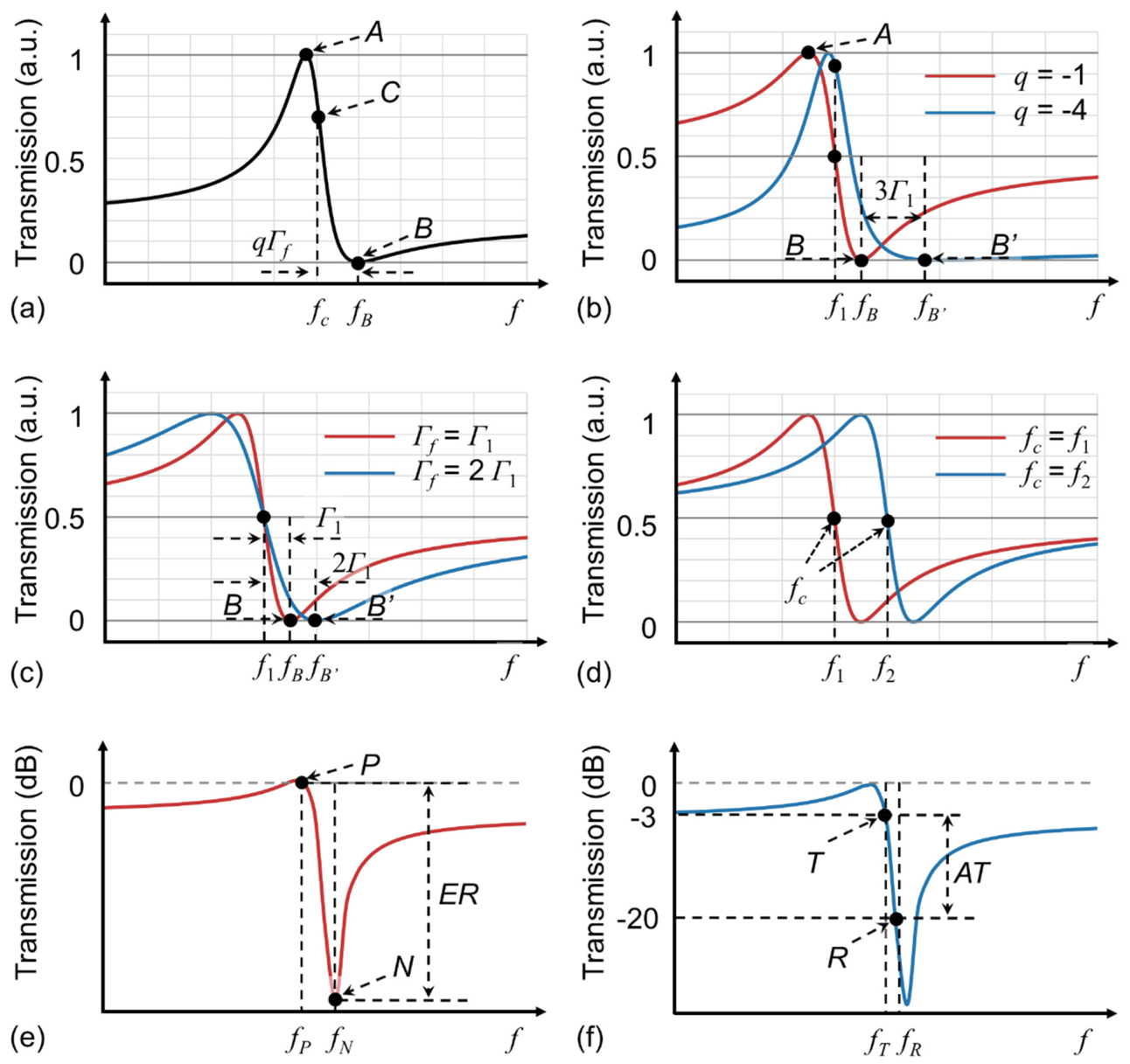
Figure 2.
Transversal filter system. (a) Schematic illustration for the operation principle of a microwave (MW) transversal filter system, where Δt is the time delay between adjacent channels, and a0, a1, …, aM - 1 are the tap coefficients in each channel. FT: Fourier transform. IFT: inverse Fourier transform. (b) Schematic diagram and processing flow of a microwave photonic (MWP) transversal filter system with an optical microcomb source. OSS: Optical spectral shaper. EOM: Electro-optic modulator. PD: photodetector.
Figure 2.
Transversal filter system. (a) Schematic illustration for the operation principle of a microwave (MW) transversal filter system, where Δt is the time delay between adjacent channels, and a0, a1, …, aM - 1 are the tap coefficients in each channel. FT: Fourier transform. IFT: inverse Fourier transform. (b) Schematic diagram and processing flow of a microwave photonic (MWP) transversal filter system with an optical microcomb source. OSS: Optical spectral shaper. EOM: Electro-optic modulator. PD: photodetector.
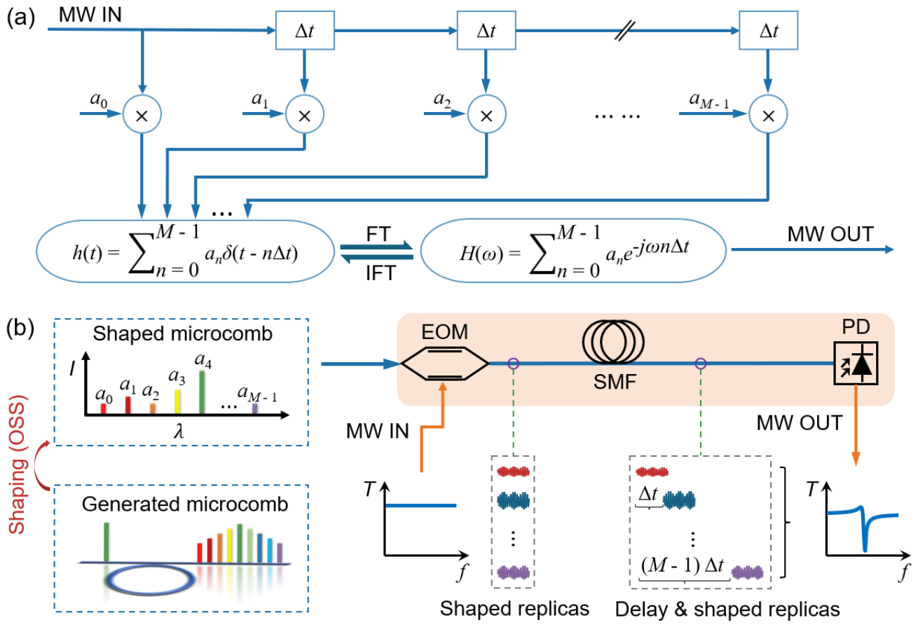
Figure 3.
Simulated spectral response of Fano filters with q = -3, Гf = 0.2 GHz, and fc = 5 GHz, realized using a microcomb-based MWP transversal filter system. (a-i) – (a-iv) Designed tap coefficients for Fano filters with various tap numbers of M = 11, 21, 41, and 81, respectively. (b) Simulated amplitude response for the Fano filters in (a). (c) Slope rate (SR) and roll-off rate (ROR) versus M, which are calculated based on the results in (b).
Figure 3.
Simulated spectral response of Fano filters with q = -3, Гf = 0.2 GHz, and fc = 5 GHz, realized using a microcomb-based MWP transversal filter system. (a-i) – (a-iv) Designed tap coefficients for Fano filters with various tap numbers of M = 11, 21, 41, and 81, respectively. (b) Simulated amplitude response for the Fano filters in (a). (c) Slope rate (SR) and roll-off rate (ROR) versus M, which are calculated based on the results in (b).
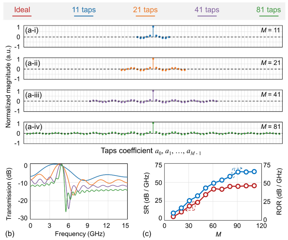
Figure 4.
Simulated response of Fano filters with various asymmetry factors q, resonance linewidth Гf, and center frequencies fc, realized using a microcomb-based MWP transversal filter system. (a-i) Simulated spectral response for q = -1, -2, and -3 at fixed fc = 5 GHz and Γf = 0.2 GHz. (a-ii) Calculated SR and ROR versus q. (b-i) Simulated spectral response for Γf = 0.1, 0.5, and 1 GHz at fixed fc = 5 GHz and q = -3. (b-ii) Calculated SR and ROR versus Γf. (c-i) Simulated spectral response for fc = 3, 5, and 7 GHz at fixed q = -3 and Γf = 0.2 GHz. (c-ii) Calculated SR and ROR versus fc.
Figure 4.
Simulated response of Fano filters with various asymmetry factors q, resonance linewidth Гf, and center frequencies fc, realized using a microcomb-based MWP transversal filter system. (a-i) Simulated spectral response for q = -1, -2, and -3 at fixed fc = 5 GHz and Γf = 0.2 GHz. (a-ii) Calculated SR and ROR versus q. (b-i) Simulated spectral response for Γf = 0.1, 0.5, and 1 GHz at fixed fc = 5 GHz and q = -3. (b-ii) Calculated SR and ROR versus Γf. (c-i) Simulated spectral response for fc = 3, 5, and 7 GHz at fixed q = -3 and Γf = 0.2 GHz. (c-ii) Calculated SR and ROR versus fc.
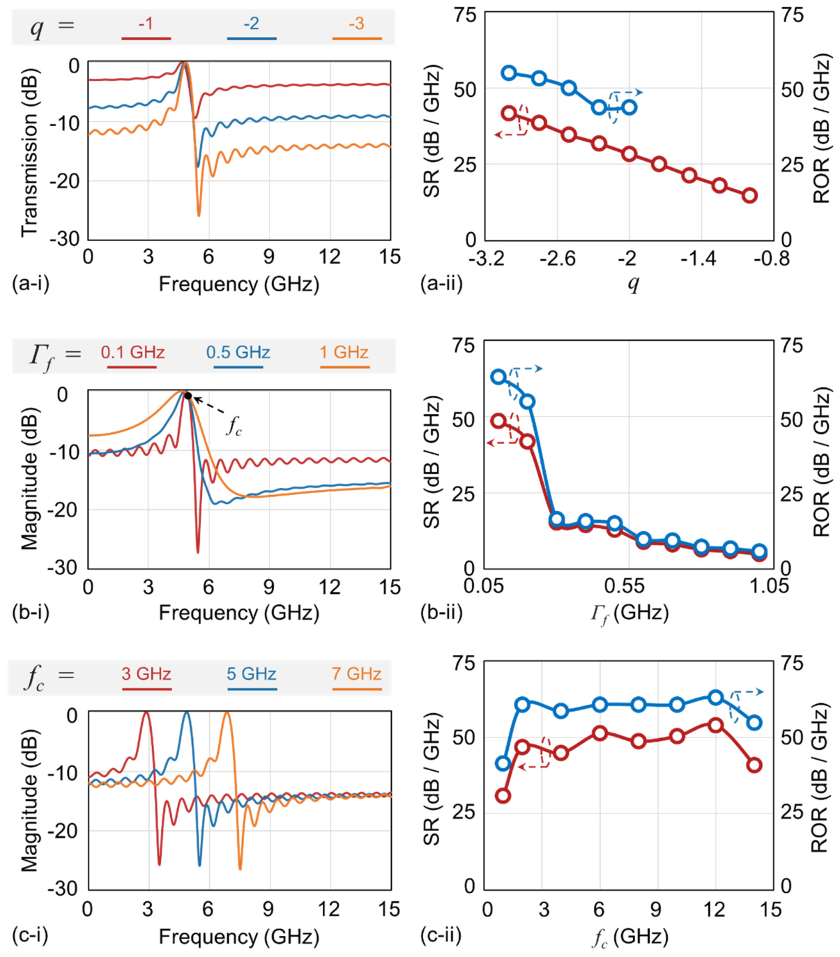
Figure 5.
Schematic of the experimental setup for demonstrating reconfigurable microcomb-based MWP Fano filters. CW laser: continuous-wave laser. EDFA: erbium-doped fiber amplifier. PC: polarization controller. MRR: micro-ring resonator. TC: temperature controller, OSS: optical spectral shaper. OSA: optical spectrum analyzer. EOM: electro-optic modulator. SMF: single-mode fiber. OC: optical coupler. BPD: balanced photodetector. VNA: vector network analyzer.
Figure 5.
Schematic of the experimental setup for demonstrating reconfigurable microcomb-based MWP Fano filters. CW laser: continuous-wave laser. EDFA: erbium-doped fiber amplifier. PC: polarization controller. MRR: micro-ring resonator. TC: temperature controller, OSS: optical spectral shaper. OSA: optical spectrum analyzer. EOM: electro-optic modulator. SMF: single-mode fiber. OC: optical coupler. BPD: balanced photodetector. VNA: vector network analyzer.
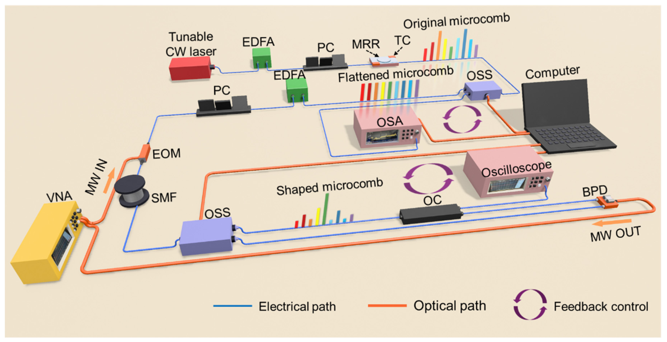
Figure 6.
Optical microcomb generation. (a) Schematic of a doped silica MRR used for optical microcomb generation. (b) Schematic illustration of optical microcomb generation from the MRR in (a). (c) Microscope image of the fabricated doped silica MRR. (d) Optical spectrum of soliton crystal microcomb generated by the MRR in (c). (e) Zoom-in view of the spectrum in (d) within telecom C band.
Figure 6.
Optical microcomb generation. (a) Schematic of a doped silica MRR used for optical microcomb generation. (b) Schematic illustration of optical microcomb generation from the MRR in (a). (c) Microscope image of the fabricated doped silica MRR. (d) Optical spectrum of soliton crystal microcomb generated by the MRR in (c). (e) Zoom-in view of the spectrum in (d) within telecom C band.
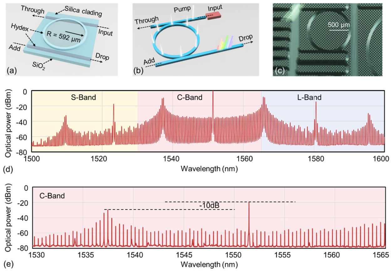
Figure 7.
Experimental results of MWP Fano filters with various tap numbers of M = 11, 21, 41, and 81. (a) Designed tap coefficients (circles) and measured optical spectra of shaped comb lines (solid lines) for (i) M = 11, (ii) M = 21, (iii) M = 41, and (iv) M = 81, where yellow circles and lines represent positive tap coefficients, and orange circles and lines correspond to negative tap coefficients. (b) Measured MW amplitude response corresponding to the results in (a). (c) SR and ROR versus M calculated based on the results in (b). In (a) ‒ (c), the Fano characteristic parameters are q = -3, Гf = 0.2 GHz, and fc = 5 GHz.
Figure 7.
Experimental results of MWP Fano filters with various tap numbers of M = 11, 21, 41, and 81. (a) Designed tap coefficients (circles) and measured optical spectra of shaped comb lines (solid lines) for (i) M = 11, (ii) M = 21, (iii) M = 41, and (iv) M = 81, where yellow circles and lines represent positive tap coefficients, and orange circles and lines correspond to negative tap coefficients. (b) Measured MW amplitude response corresponding to the results in (a). (c) SR and ROR versus M calculated based on the results in (b). In (a) ‒ (c), the Fano characteristic parameters are q = -3, Гf = 0.2 GHz, and fc = 5 GHz.
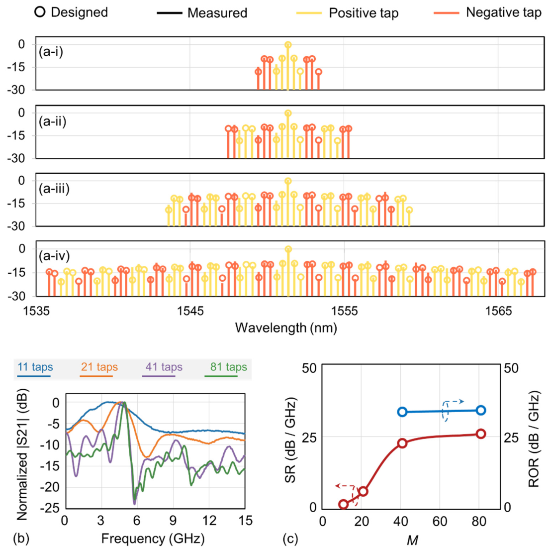
Figure 8.
Experimental results of reconfigurable MWP Fano filters. (a-i) Measured MW amplitude response for q = -1, -2 and -3 at fixed fc = 5 GHz and Γf = 0.2 GHz. (a-ii) Calculated SR and ROR based on the results in (a-i). (b-i) Measured MW amplitude response for Γf = 0.2, 0.8 and 2.5 GHz at fixed fc = 5 GHz and q = -3. (b-ii) Calculated SR and ROR based on the results in (b-i). (c-i) Measured MW amplitude response for fc = 5, 7 and 9 GHz at fixed q = -3 and Γf = 0.2 GHz. (c-ii) Calculated SR and ROR based on the results in (c-i).
Figure 8.
Experimental results of reconfigurable MWP Fano filters. (a-i) Measured MW amplitude response for q = -1, -2 and -3 at fixed fc = 5 GHz and Γf = 0.2 GHz. (a-ii) Calculated SR and ROR based on the results in (a-i). (b-i) Measured MW amplitude response for Γf = 0.2, 0.8 and 2.5 GHz at fixed fc = 5 GHz and q = -3. (b-ii) Calculated SR and ROR based on the results in (b-i). (c-i) Measured MW amplitude response for fc = 5, 7 and 9 GHz at fixed q = -3 and Γf = 0.2 GHz. (c-ii) Calculated SR and ROR based on the results in (c-i).
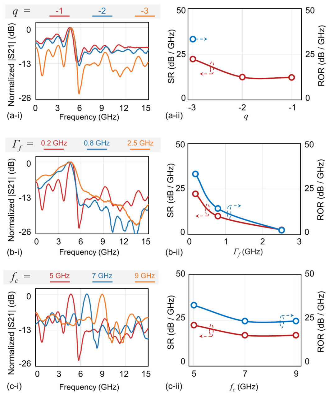
Disclaimer/Publisher’s Note: The statements, opinions and data contained in all publications are solely those of the individual author(s) and contributor(s) and not of MDPI and/or the editor(s). MDPI and/or the editor(s) disclaim responsibility for any injury to people or property resulting from any ideas, methods, instructions or products referred to in the content. |
© 2026 by the authors. Licensee MDPI, Basel, Switzerland. This article is an open access article distributed under the terms and conditions of the Creative Commons Attribution (CC BY) license (http://creativecommons.org/licenses/by/4.0/).
Copyright: This open access article is published under a Creative Commons CC BY 4.0 license, which permit the free download, distribution, and reuse, provided that the author and preprint are cited in any reuse.


