
Submitted:
13 July 2026
Posted:
14 July 2026
You are already at the latest version
Abstract
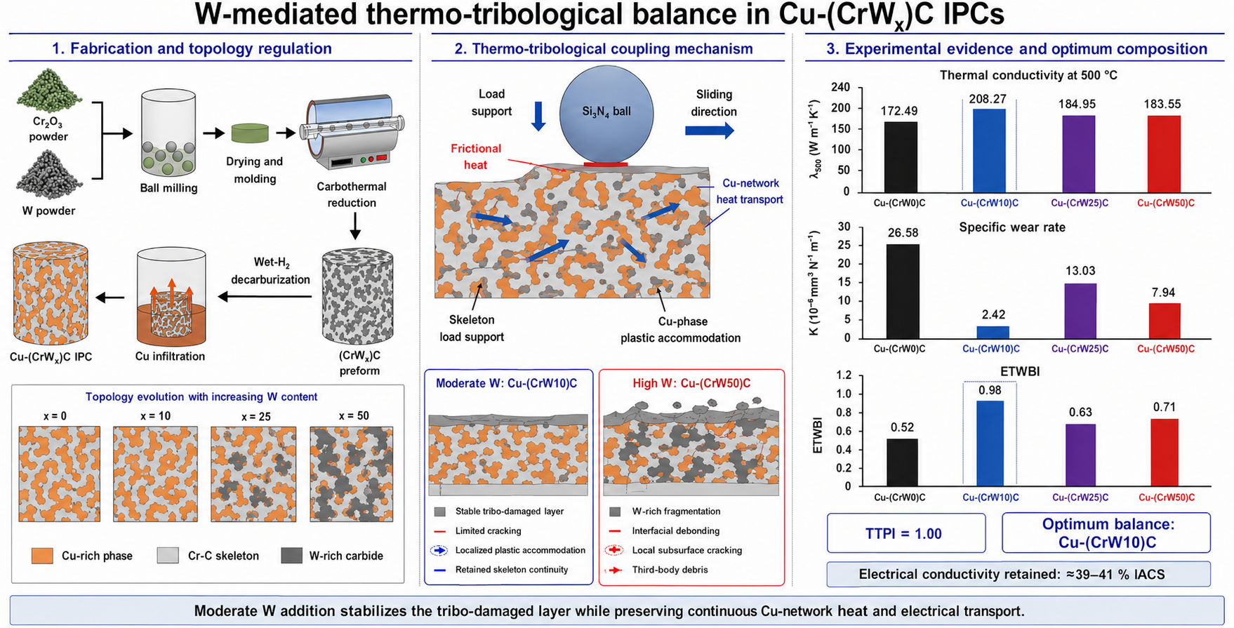
Cu-based interpenetrating phase composites (IPCs) represent a paradigm for sliding electrical contacts where the synergy between thermal management, wear resistance, and electrical transport is critical. Herein, we engineer Cu-(CrWₓ)C IPCs (x = 0, 10, 25, 50 wt%) via pressureless infiltration, elucidating a tungsten-mediated architectural stabilization mechanism. We demonstrate that controlled W incorporation refines the carbide skeleton, optimizing the load-transfer efficiency between the rigid ceramic network and the continuous Cu-rich functional phase. Microstructural characterization (XRD, SEM/EDS) confirms the intact three-dimensional interpenetration, with higher W content promoting the segregation of W-rich domains. Quasi-static compression (10-3 s-1) validates the structural robustness under large-strain regimes. Notably, all composites retain high electrical conductivities (~39–41 % IACS); the Cu-(CrW10)C variant exhibits the peak thermal conductivity at 500 °C. Tribological evaluations reveal that optimal wear resistance is decoupled from peak hardness; instead, it arises from the stabilization of a skeleton-supported tribo-damaged layer facilitated by moderate W addition. Conversely, excessive W enrichment induces brittle fragmentation and interfacial debonding, exacerbating third-body abrasion. Quantitative analysis using a Thermo-Tribological Performance Index (TTPI) and an Electrical-Thermal-Wear Balance Index (ETWBI) confirms that Cu-(CrW10)C achieves the optimal equilibrium among material removal resistance, heat dissipation, and dimensional stability. This work establishes a design strategy for high-performance IPCs by leveraging architectural tuning to reconcile traditionally conflicting property requirements.
Keywords:
Cu-based interpenetrating phase composites
; tungsten alloying
; sliding electrical contacts
; tribo-damaged layer stabilization
; thermal-electrical-wear synergy
; pressureless infiltration
1. Introduction
Sliding-contact components used in electrical contacts, thermal-management units, brake/friction pairs, and other moving assemblies rarely fail through purely mechanical or purely thermal processes. During sliding, asperity ploughing, adhesive shearing, tribo-oxidation, and debris generation occur concurrently with friction-induced temperature rise. The resulting heat can accelerate surface softening, oxidation, interfacial degradation, and thermal-stress accumulation, while continuous material removal changes the real contact area, load-transfer path, and heat-dissipation condition. Therefore, materials intended for such environments should not be evaluated solely by friction coefficient, hardness, or wear rate. A more relevant design criterion is the simultaneous control of material removal, heat dissipation, and thermal dimensional stability, with electrical transport also remaining critical for conductive sliding-contact applications [1,2].
This requirement creates an intrinsic materials-design trade-off. Hard ceramics and refractory carbides resist asperity penetration and abrasive ploughing, but their limited fracture toughness and poor damage accommodation can lead to brittle cracking, unstable hard debris, and local delamination during repeated sliding. By contrast, Cu and Cu-based alloys provide high electrical and thermal conductivity together with plastic accommodation; however, their low hardness and limited resistance to abrasive wear restrict their direct use under severe contact conditions. Particle-reinforced Cu composites partly mitigate this problem, yet isolated reinforcements and discontinuous metallic pathways often hinder the simultaneous realization of stable load bearing, continuous transport, and effective crack/debris control [3,4,5,6,7,8,9,10].
Interpenetrating phase composites (IPCs) provide a more suitable structural solution because both constituent phases are spatially continuous. In Cu-based IPCs, a continuous ceramic skeleton can support the contact load and resist ploughing, whereas a continuous Cu-rich phase can provide heat/electrical transport, plastic accommodation, and crack blunting. This dual-network architecture differs fundamentally from conventional particle-reinforced composites, because load transfer, thermal conduction, and damage accommodation can all proceed through connected pathways. Consequently, the performance of Cu-based IPCs is governed not only by the intrinsic properties of the ceramic and metallic phases, but also by skeleton topology, network connectivity, and local chemical heterogeneity [11,12,13,14,15,16,17,18].
For Cr-C carbide/Cu IPCs, the ceramic skeleton is not simply a passive hard framework; it determines whether the worn surface remains supported or evolves into a source of hard third-body debris. If the skeleton is too weak or poorly connected, it cannot effectively protect the Cu-rich phase from severe ploughing and material removal. Conversely, if the skeleton is excessively hard, brittle, or compositionally heterogeneous, local stress concentration, interfacial debonding, and carbide fragmentation may be promoted. W-containing carbides offer an effective route for skeleton regulation because W can modify the local carbide constitution and morphology of the Cr-C framework. However, W addition should not be considered a monotonic hardening strategy. Moderate W-mediated regulation may stabilize the skeleton-supported tribo-damaged layer while preserving Cu-network transport, whereas excessive W-rich carbide enrichment may intensify fragmentation and third-body abrasion [19,20,21,22,23,24].
Although Cu-based IPCs are promising for conductive, thermally dissipative, and wear-resistant components, the coupling among skeleton regulation, electrical/thermal transport, thermal expansion, and wear damage remains insufficiently understood. Many studies evaluate hardness, friction coefficient, wear rate, electrical conductivity, or thermal conductivity as separate properties. Such single-property assessment can be misleading for sliding-contact materials: a low friction coefficient does not necessarily guarantee low volume loss when the tribo-damaged layer is unstable, and a hard material may still wear rapidly if hard fragments continuously generate third-body abrasives. Likewise, a low wear rate alone is insufficient when frictional heat cannot be dissipated or thermal expansion induces dimensional instability. Complementary materials-development studies have shown that data-driven high-throughput experiments can accelerate mapping of multicomponent composition-property relationships, while micron-grain/nano-twin engineering can strongly influence electrical transport in Cu [25,26]. More recent materials-informatics research has further shown that nonlinear relationships and inter-feature effects should be evaluated explicitly when constructing property-prediction models for multicomponent alloys [37]. A coupled evaluation framework is therefore needed to identify compositions that balance skeleton-supported wear resistance with Cu-network transport and thermal-expansion constraint.
In this work, Cu-(CrWₓ)C IPCs with different W contents (x = 0, 10, 25, and 50 wt%) were fabricated by infiltrating Cu into porous Cr-W-C carbide preforms. Their phase constitution, preform morphology, interpenetrating architecture, quasi-static compressive response, thermophysical and electrical properties, hardness, friction behavior, wear volume, worn-surface chemistry, and subsurface damage were systematically investigated. A thermo-tribological performance index (TTPI) was used to correlate specific wear rate, thermal conductivity, and thermal expansion, while electrical conductivity and hardness were introduced as auxiliary indicators of Cu-network continuity and resistance to asperity penetration, respectively. The objective was to reveal how W-mediated carbide-skeleton regulation controls the balance between skeleton-supported wear resistance and Cu-network transport, and to establish a structural design principle for electro-thermo-tribologically balanced Cu-based IPCs.
2. Experimental Procedure
2.1. Preparation of (Crwₓ)c Preforms and Cu-(crwₓ)c Ipcs
Commercial Cr₂O₃ powder (D50 ≈ 10 μm; Sichuan Minghong Hengjin Technology Co., Ltd., China), W powder (99.95 wt.%, 1-3 μm; Adamas Reagent Co., China), and Cu powder (99.9 wt.%, 325 mesh; Adamas Reagent Co., China) were used as starting materials. Based on 100 g of Cr₂O₃, 0, 10, 25, or 50 g of W powder was added to prepare four porous carbide preform compositions, denoted as (CrW0)C, (CrW10)C, (CrW25)C, and (CrW50)C, respectively. The Cr₂O₃ and W powders were mixed in zirconia jars with zirconia balls using absolute ethanol as the milling medium. Ball milling was performed at 150 rpm for 12 h with a ball-to-powder ratio of 5:1 and a ball-size ratio of 5 mm:10 mm:20 mm = 1:1:1, followed by forced-air drying at 60 °C for 12 h.
The dried powders were uniaxially pressed at 100 MPa to obtain green compacts with the dimensions required for subsequent machining and testing. Carbothermal reduction was performed by heating the compacts to 1150 °C at 5 °C min⁻¹ under CH₄/H₂/Ar gas flow rates of 40/180/180 sccm, followed by holding for 12–20 h depending on sample thickness. After carbothermal reduction, the atmosphere was switched to H₂ containing approximately 150 ppm H₂O at 500 sccm for 3–5 h to remove residual free carbon and improve the interfacial condition for Cu infiltration.
Pressureless Cu infiltration was then conducted at 1250 °C for 5 h in dry H₂ (200 sccm) using BN-coated alumina crucibles. The Cu source was placed beneath the porous carbide preform so that molten Cu spontaneously infiltrated upward into the open carbide skeleton. After furnace cooling, the infiltrated IPCs were ground, polished, and machined into the required specimens. The final composites are denoted as Cu-(CrW0)C, Cu-(CrW10)C, Cu-(CrW25)C, and Cu-(CrW50)C.
2.2. Phase and Microstructure Characterization
The phase constitution of the porous preforms and Cu-infiltrated IPCs was characterized by X-ray diffraction (XRD; Bruker D2, Bruker AXS SE, Germany) using Cu Kα radiation (λ = 1.5406 Å). Diffraction patterns were collected over a 2θ range of 20–80° with a step size of 0.02° and a scan rate of 2° min⁻¹. Reference PDF cards were used only for phase identification and comparison.
The morphology and elemental distribution of the porous preforms and IPCs were examined by field-emission scanning electron microscopy (SEM; Gemini 300, Carl Zeiss AG, Germany) equipped with energy-dispersive X-ray spectroscopy (EDS; Ultim Max 65, Oxford Instruments, UK). Cross-sectional IPC specimens were ground, polished, and ultrasonically cleaned before observation. Backscattered-electron imaging was used to distinguish the Cu-rich phase, Cr-C carbide skeleton, and W-rich regions. Worn surfaces were observed directly after sliding tests, whereas wear-scar cross sections were prepared perpendicular to the wear track by cutting, mounting, grinding, and polishing. EDS mapping and point analysis were used to identify Cu-rich oxidized debris, exposed carbide skeletons, and W-rich hard-phase regions in the tribo-damaged areas.
2.3. Thermophysical and Electrical Characterization
Thermal diffusivity was measured at 25, 300, and 500 °C using a laser flash analyzer (NETZSCH LFA 467, NETZSCH-Gerätebau GmbH, Germany) under an N₂ purge/protective atmosphere. Specimens for laser flash analysis were machined into plates with nominal dimensions of 10 mm × 10 mm × 2 mm. Before testing, the specimen surfaces were ground and polished without graphite coating. Room-temperature density was determined by the Archimedes method and used for thermal-conductivity calculation. At each temperature, three shots were collected and analyzed using the standard model with pulse correction. The laser voltage and pulse width were 250 V and 0.40 ms, respectively. Thermal conductivity was calculated from the measured thermal diffusivity, heat capacity, and density according to [27]
where λ(T), Dth(T), Cp(T), and ρ(T) denote thermal conductivity, thermal diffusivity, heat capacity, and density at temperature T, respectively. The average value and standard deviation of three measurements were used for each temperature point. Thermal expansion was measured using a dilatometer (NETZSCH DIL 402 C, NETZSCH-Gerätebau GmbH, Germany) under an Ar atmosphere. Cylindrical specimens with dimensions of φ3 mm × 10 mm were used for dilatometry. The specimens were heated at 5 °C min⁻¹. The relative length change, ΔL/L₀, was recorded during heating, and the thermal-expansion curves in the main text were referenced to 30 °C. The average coefficient of thermal expansion from 30 to 500 °C was calculated according to
(2)
where ΔL/L₀ is the relative length change between 30 and 500 °C.
Room-temperature electrical conductivity was measured using an eddy-current conductivity meter (FD102, Xiamen First Electronic Technology Co., Ltd., China) at a working frequency of 120 kHz. Polished IPC specimens were measured at 20 °C, and at least five positions were tested for each composition. The instrument was calibrated with Al and pure Cu reference blocks before measurement. Average values are reported in % IACS, with corresponding standard deviations used as error bars. The measured electrical conductivity was used to evaluate the continuity of the Cu-rich metallic network in the IPCs. For the transport-consistency analysis, the electrical conductivity measured at 20 °C was corrected to 30 °C and then used to estimate the electronic thermal conductivity via the Wiedemann-Franz relation [28].
2.4. Hardness, Quasi-Static Compression, Tribological Testing and Wear Analysis
Vickers microhardness was measured under an HV0.1 condition with a dwell time of 15 s. Ten valid indentations were collected for each composition, and average values were used for the hardness-specific wear-rate comparison. Before tribological testing, the IPC specimens were ground, polished, and ultrasonically cleaned to ensure comparable initial surface conditions.
Quasi-static compression tests were performed at room temperature on cylindrical IPC specimens with a nominal diameter of approximately 3 mm and a height of approximately 6 mm. The engineering strain rate was 0.001 s⁻¹. Engineering stress and strain were calculated from the initial specimen dimensions and the recorded load-displacement data. These tests were used to assess the large-strain load-bearing response of the interpenetrating Cu/carbide architecture.
Ball-on-disk sliding wear tests were conducted on a Bruker UMT-Tribolab tribometer using a Si₃N₄ counter ball under a normal load of 12 N. The rotation speed was 200 r min⁻¹, the wear-track radius was 7 mm, and the actual sliding time was 1202 s, corresponding to a total sliding distance of 176.22 m. The coefficient of friction (COF) was recorded continuously during sliding, and the steady-state COF was calculated for t ≥ 250 s.
After testing, the worn surfaces and cross sections were characterized by SEM/EDS. Three-dimensional wear morphology was measured by optical profilometry, and wear volume was obtained by integrating the wear-scar profile over the circular wear track. The measured wear volume was then used to calculate the specific wear rate and the thermo-tribological coupling indicators described below.
2.5. Thermo-Tribological Coupling Calculation
To quantify the thermo-tribological coupling response, frictional energy input, material removal, heat-dissipation capability, and thermal-expansion tendency were correlated using the following equations. The linear sliding speed and sliding distance were calculated as
(3)
(4)
where r is the wear-track radius, n is the rotation speed, and t is the sliding time. The specific wear rate was calculated according to Archard’s relation [29] as
(5)
where V is the wear volume and Fₙ is the normal load. Frictional work and frictional heat-generation power were estimated using the average friction coefficient, μavg:
(6)
(7)
The wear loss per unit frictional work was defined as
(8)
The relative heat-accumulation tendency and thermal-stress tendency were described as
(9)
(10)
Finally, the thermo-tribological performance index (TTPI) and normalized TTPI were defined as
(11)
(12)
A higher TTPI represents a better balance among low wear rate, high thermal conductivity, and reduced thermal-expansion-induced instability. In this work, TTPI values were normalized to that of Cu-(CrW10)C to enable direct comparison among the four IPC compositions.
To further evaluate the coupled electrical-thermal-wear balance of the present IPCs, an electrical-thermal-wear balance index (ETWBI) was introduced. For the i-th composition, the normalized thermal-conductivity, electrical-conductivity, wear-rate and thermal-expansion terms were defined as follows. The favorable thermal-conductivity and electrical-conductivity terms were normalized by their maximum values, whereas the wear-rate and thermal-expansion terms were normalized in an inverse manner because lower wear rate and lower thermal expansion are beneficial:
(13)
(14)
(15)
(16)
where the subscript n denotes a normalized quantity, and λ500, σ, K and α30-500 are the thermal conductivity at 500 °C, room-temperature electrical conductivity, specific wear rate and average coefficient of thermal expansion from 30 to 500 °C, respectively.
The ETWBI was then defined as the geometric mean of the four normalized terms:
(17)
The geometric-mean form penalizes any severely deficient property and is therefore suitable for assessing balance rather than single-property maximization. A higher ETWBI indicates a better simultaneous balance among high-temperature heat dissipation, Cu-network electrical transport, wear resistance and thermal-dimensional stability.
3. Results and Discussion
3.1. Phase Constitution of Preforms and Ipcs
The XRD patterns of the (CrWₓ)C preforms and corresponding Cu-(CrWₓ)C IPCs are shown in Figure 1. The (CrW0)C preform is mainly indexed to Cr₃C₂-related reflections, indicating the formation of a Cr-C carbide skeleton. With increasing W content, WC-related reflections become increasingly evident, and the enlarged region shows changes in peak shape and position, suggesting the formation of W-rich carbide regions or (Cr,W)ₓC-related solid-solution carbides. After Cu infiltration, distinct Cu reflections appear while the carbide-related peaks are retained, confirming successful incorporation of the Cu phase and stability of the Cr-W-C skeleton during infiltration. No obvious Cu-Cr or Cu-W intermetallic peaks are observed, implying limited interfacial reaction between the Cu phase and the carbide skeleton.
3.2. W-Mediated Morphology Evolution of Porous Carbide Preforms
The SEM images and EDS mappings of the porous preforms are shown in Figure 2. All preforms exhibit an open, interconnected skeleton architecture, which provides continuous infiltration channels for the subsequent Cu melt. The (CrW0)C preform shows a relatively continuous and rounded carbide network, whereas the W-containing preforms display rougher skeleton surfaces and more pronounced local carbide aggregates. EDS mapping confirms that Cr and C are distributed along the skeleton, while the W signal becomes progressively stronger with increasing W content. W is not completely uniformly distributed, indicating the formation of W-rich carbide regions within the Cr-C skeleton. Such W-mediated skeleton regulation is expected to influence both load transfer and local damage evolution during sliding wear.
3.3. Interpenetrating Architecture After Cu Infiltration
Figure 3 shows the SEM images and EDS mappings of the Cu-(CrWₓ)C IPCs. The Cu-rich phase successfully fills the open pores of the preforms and forms a continuous metallic network that interpenetrates with the Cr-W-C carbide skeleton. The complementary distribution of Cu and Cr/C-rich regions confirms the formation of a typical IPC architecture. W-rich regions become more pronounced in Cu-(CrW25)C and Cu-(CrW50)C, consistent with the XRD and preform EDS results. The relatively sharp elemental boundaries between the Cu phase and the carbide skeleton indicate good chemical compatibility and limited interfacial reaction. Cu-(CrW10)C exhibits a more balanced distribution of the carbide skeleton and Cu-rich phase, whereas higher W contents lead to more pronounced enrichment of W-rich carbides.
3.4. Quasi-Static Compressive Response
The quasi-static compressive curves at 0.001 s⁻¹ are shown in Figure 4. All four IPCs exhibit a rapid initial stress increase followed by a broad transition region and a pronounced large-strain load-bearing response, indicating that the interpenetrating Cu/carbide architecture can sustain high compressive loading while accommodating local deformation. Cu-(CrW50)C shows a higher early-stage stress level, which is consistent with the presence of W-rich hard regions; however, noticeable stress drops appear in the intermediate strain range, suggesting local skeleton fragmentation, interfacial damage, or redistribution of the load-bearing path. By contrast, Cu-(CrW10)C and Cu-(CrW25)C maintain smoother post-transition responses, while Cu-(CrW0)C shows a later stress increase at larger strain. These results support the tribological interpretation that the optimum wear resistance should not be attributed simply to the highest instantaneous compressive stress or hardness, but to the stability of the skeleton-supported tribo-damaged layer and the ability of the continuous Cu network to accommodate friction-induced local stress.
3.5. Thermophysical and Electrical Properties
The thermophysical and electrical properties of the IPCs are summarized in Figure 5. The room-temperature electrical conductivity remains within a narrow range of approximately 39–41% IACS for all compositions, indicating that the continuous Cu-rich network is retained after W-mediated regulation of the carbide skeleton. Because electrical transport in the present Cu-based IPCs is mainly provided by the interconnected Cu-rich phase, the retained conductivity confirms that W addition does not severely disrupt the metallic conduction pathway.
The high thermal conductivity of all samples also originates from the continuous Cu-rich network, which provides an efficient heat-transfer pathway. Cu-(CrW10)C exhibits the highest thermal conductivity at 500 °C, reaching 208.27 W m⁻¹ K⁻¹, indicating that moderate W addition preserves effective heat dissipation. However, the thermal-conductivity trend does not strictly follow the room-temperature electrical-conductivity trend, suggesting that thermal transport is also affected by carbide-skeleton topology, Cu/carbide interfacial scattering, and the distribution of W-rich regions.
The thermal-expansion curves referenced to 30 °C show a continuous increase in length with temperature. The average CTE values from 30 to 500 °C are 13.23–13.98 × 10⁻⁶ K⁻¹, which are lower than the CTE of pure Cu owing to the constraint imposed by the carbide skeleton. Although Cu-(CrW10)C does not show the lowest CTE, it maintains an acceptable thermal expansion coefficient and exhibits the highest thermal stability index, λ₅₀₀/α₃₀–₅₀₀.
To further compare the measured thermal conductivity with the electronic transport capability estimated from electrical conductivity, a transport consistency factor, ηTC, was introduced. A value close to 100% indicates that the measured room-temperature thermal conductivity approaches the electronic thermal conductivity estimated from the corrected electrical conductivity, confirming the dominant contribution of the continuous Cu-rich network to heat and charge transport. The deviation from 100% reflects additional thermal-transport losses associated with Cu/carbide interfaces, skeleton topology, and W-rich heterogeneity. These results provide the thermophysical and electrical basis for analyzing the subsequent thermo-tribological response.
3.6. Friction Coefficient and Quantitative Wear Resistance
The friction and wear results are shown in Figure 6. The COF-time curves display typical running-in and steady-state stages, with the steady-state region defined as t ≥ 250 s. Cu-(CrW50)C exhibits the lowest steady-state COF, indicating reduced interfacial shear resistance. However, this sample does not exhibit the lowest specific wear rate. Instead, Cu-(CrW10)C shows the lowest specific wear rate of 2.42 × 10⁻⁶ mm³ N⁻¹ m⁻¹, nearly one order of magnitude lower than that of Cu-(CrW0)C. Together with the compressive response in Figure 4, this result demonstrates that wear resistance is governed not by friction coefficient, hardness, or compressive load-bearing capacity alone, but by the stability of the skeleton-supported worn layer and the suppression of material removal.
3.7. Worn-Surface Morphology
The worn-surface morphologies are shown in Figure 7. At low magnification, the wear-scar widths of Cu-(CrW0)C, Cu-(CrW10)C, Cu-(CrW25)C, and Cu-(CrW50)C are 724.6, 602.0, 658.7, and 495.7 μm, respectively. Although Cu-(CrW50)C shows the narrowest wear scar, the three-dimensional wear-volume results indicate that Cu-(CrW10)C undergoes the lowest material loss. High-magnification SEM images reveal pronounced wear debris and ploughing grooves in Cu-(CrW0)C, indicating severe third-body abrasion. Cu-(CrW10)C exhibits a comparatively more stable worn surface with limited debris accumulation. Cu-(CrW25)C shows evident local cracks and grooves, suggesting intensified carbide detachment and delamination wear. Cu-(CrW50)C still exhibits cracks, debris, and local grooves, implying that exposure and fragmentation of W-rich hard phases contribute to material removal despite the narrow wear scar.
3.8. Eds Mapping of Worn Surfaces
To further identify the chemical nature of the wear debris and tribo-damaged regions, EDS elemental mapping was performed on the worn surfaces, as shown in Figure 8. Local enrichment of Cu and O indicates the formation of Cu-rich oxidized debris or tribo-oxidized films during sliding. In contrast, Cr- and C-rich regions correspond to exposed carbide skeletons or detached carbide fragments, which can act as third-body abrasives. In Cu-(CrW50)C, local W enrichment indicates exposure of W-rich carbide skeletons or W-rich hard debris. These mapping results confirm that the wear process involves both tribo-oxidation of the Cu-rich phase and fragmentation of the carbide skeleton. The corresponding EDS point-scan results are provided in the Supplementary Information.
3.9. Cross-Sectional Damage Beneath Worn Scars
Cross-sectional SEM observations were conducted to clarify subsurface damage evolution during sliding, as shown in Figure 9. For Cu-(CrW0)C, a distinct tribo-damaged layer forms beneath the worn surface, accompanied by interfacial debonding and carbide fragmentation, indicating insufficient load-transfer stability between the Cu-rich phase and the carbide skeleton. In Cu-(CrW10)C, although a tribo-damaged layer and limited subsurface cracks are observed, the damage remains relatively localized and is accompanied by plastic deformation traces, suggesting effective accommodation of friction-induced stress. Cu-(CrW25)C exhibits more pronounced subsurface cracks and delamination cracking together with carbide fragmentation, implying unstable material removal. For Cu-(CrW50)C, local fragmentation and interfacial debonding remain evident, and the exposed W-rich skeleton indicates that hard-phase-enriched regions directly participate in the wear process. These results demonstrate that the superior wear resistance of Cu-(CrW10)C originates from the improved stability of the tribo-damaged layer and the more balanced cooperation between carbide-skeleton support and Cu-phase deformation.
3.10. Quantitative Thermo-Tribological Coupling Analysis
The key thermo-tribological coupling indicators calculated from frictional work, wear volume, thermal conductivity, and thermal expansion are summarized in Table 1. Cu-(CrW10)C exhibits the lowest specific wear rate and the lowest wear loss per unit frictional work, indicating that material removal under a given frictional energy input is effectively suppressed. It also possesses the highest thermal conductivity at 500 °C while maintaining an acceptable α₃₀–₅₀₀. Consequently, Cu-(CrW10)C achieves the highest normalized TTPI, confirming the most favorable balance among frictional-damage resistance, heat dissipation, and thermal dimensional stability. Hardness and the quasi-static compression response are used to interpret mechanical support and resistance to local deformation, whereas electrical conductivity is used to verify the continuity of the Cu-rich transport network. These parameters are not directly included in the TTPI expression, which avoids reducing the IPC response to a single mechanical or transport parameter and emphasizes that the optimum composition must satisfy multiple constraints simultaneously.
Based on the parameters listed in Table 1, the thermo-tribological coupling performance is visualized in Figure 10. Cu-(CrW10)C combines the lowest wear rate, the lowest wear loss per unit frictional work, the highest thermal conductivity at 500 °C, and the highest normalized TTPI. These results indicate that its superior performance is not derived from a low friction coefficient, high hardness, or high compressive load-bearing capacity alone, but from an optimized balance among friction-induced damage resistance, heat dissipation, thermal-expansion stability, and skeleton/Cu-network cooperation. The following performance-positioning analysis further compares this balanced response with reported W-Cu-based wear-resistant materials and highlights the electrical-thermal-wear balance within the present IPC series. This result identifies Cu-(CrW10)C as the composition with the most favorable thermo-tribological balance, rather than as a material optimized for a single property.
3.11. Performance Positioning and Electrical-Thermal-Wear Balance
The hardness-specific wear-rate map in Figure 11a compares the present Cu-(CrWₓ)C IPCs with reported W-Cu-based wear-resistant materials. This comparison is intended for performance positioning rather than direct ranking because reported wear rates depend strongly on counter-body material, load, sliding speed, environment, and test configuration. Even with this limitation, the present IPCs occupy a competitive region characterized by moderate hardness and low specific wear rate. The hardness inset shows that Vickers hardness increases with W content, indicating enhanced resistance to local indentation and asperity penetration. Nevertheless, the specific wear rate does not decrease monotonically with hardness, and the compression curves in Figure 4 similarly indicate that high load-bearing capacity alone does not guarantee the lowest material loss. Cu-(CrW10)C exhibits the lowest specific wear rate despite not having the highest hardness, confirming that the wear resistance of the present IPCs is governed by tribo-layer stability and debris control rather than hardness alone [30,31,32,33,34,35,36].
To highlight the IPC design advantage beyond the hardness-wear-rate comparison, an electrical-thermal-wear balance index (ETWBI) was plotted for the four present compositions in Figure 11b. As defined in Section 2.5, this internal comparison combines four normalized terms representing high-temperature heat dissipation, Cu-network electrical transport, wear resistance, and thermal dimensional stability. Cu-(CrW10)C gives the highest ETWBI, demonstrating that the optimum composition is not obtained by simply maximizing the content of W-rich hard phases. Instead, moderate W addition produces a balanced IPC architecture in which the carbide skeleton is stable enough to support the worn layer, the Cu-rich network remains sufficiently continuous for heat/electrical transport, and carbide detachment/third-body abrasion is suppressed. In contrast, higher W contents increase local hardness but promote W-rich carbide enrichment, skeleton fragmentation, and interfacial debonding, leading to unstable material removal. Therefore, the key advantage of the present Cu-(CrWₓ)C IPCs is their electrical-thermal-wear balance enabled by dual continuous networks and W-mediated skeleton regulation.
4. Conclusions
This study demonstrates that tungsten-mediated architectural stabilization is a potent strategy for reconciling the inherent trade-offs between thermal management and wear resistance in Cu-based interpenetrating phase composites (IPCs). By systematically varying the W content (x = 0, 10, 25, 50 wt%) in Cu-(CrWₓ)C IPCs fabricated via pressureless infiltration, we established a clear structure–property relationship governing the synergy between the load-bearing carbide skeleton and the functional Cu-rich network.
Microstructural characterization confirmed the integrity of the three-dimensional interpenetrating architecture. We elucidated that moderate W addition (Wx= 10 wt%) refines the carbide skeleton, which is critical for stabilizing the skeleton-supported tribo-damaged layer during sliding. This architectural optimization decouples wear resistance from conventional metrics such as peak hardness; instead, the enhanced performance of Cu-(CrW10)C stems from the effective suppression of brittle fragmentation and third-body abrasion. In contrast, excessive W enrichment promotes the agglomeration of W-rich phases, compromising interfacial bonding and accelerating material removal.
Despite these microstructural variations, all composites maintained high electrical conductivities (~39–41% IACS), validating the uninterrupted connectivity of the Cu network. Significantly, Cu-(CrW10)C exhibited superior thermal conductivity at elevated temperatures (500 °C) while retaining dimensional stability. Quantitative evaluation using the Thermo-Tribological Performance Index (TTPI) and the Electrical-Thermal-Wear Balance Index (ETWBI) further corroborated that the formulation (Wx= 10 wt%) provides the optimal equilibrium among heat dissipation, electrical transport, and wear resistance.
These findings advance the design philosophy of multifunctional IPCs by shifting the focus toward architectural tuning rather than mere compositional adjustment. The proposed W-mediated stabilization mechanism offers a robust pathway for developing high-performance sliding electrical contacts and thermal interface materials operating under extreme electromechanical coupling. Collectively, the integration of structural, thermophysical, electrical, and tribological insights establishes W-mediated skeleton regulation as a definitive strategy for achieving electro-thermo-tribological balance in Cu-based IPCs. Future work will focus on probing the electrotribological behavior and subsurface evolution under coupled mechanical-electrical fields to elucidate current-induced interfacial damage mechanisms. Additionally, the scalability of the pressureless infiltration process for fabricating complex-shaped components will be systematically evaluated.
Author Contributions
Han Hu: Writing—original draft, Methodology, Validation, Software, Formal analysis, Investigation, Data curation; Ziqiang Dong: Methodology, Formal analysis, Discussion; Yanjie Liu: Project administration, Data curation, Discussion, Resources; Yi Liu: Writing—review & editing, Supervision, Project administration, Funding acquisition, Resources, Methodology, Formal analysis, Data curation.
Data Availability Statement
The original contributions presented in this study are included in the article. Further inquiries can be directed to the corresponding author.
Acknowledgments
We thank the National Natural Science Foundation of China (No. 52373227) and the National Key R&D Program of China (Nos. 2017YFB0701502 and 2017YFB0702901) for financial support. This work was also supported by the Shanghai Professional Technical Service Center for Intelligent Design and Manufacturing of Advanced Ceramics (No. 20DZ2294000). We also acknowledge financial support from the Opening Project Fund of Materials Service Safety Assessment Facilities (MSAF-2024-107).
Conflicts of Interest
The authors declare that they have no known competing financial interests or personal relationships that could have appeared to influence the work reported in this paper.
References
- Dong, L.L.; Ahangarkani, M.; Chen, W.G.; Zhang, Y.S. Recent progress in development of tungsten-copper composites: Fabrication, modification and applications. Int. J. Refract. Met. Hard Mater. 2018, 75, 30–42. [Google Scholar] [CrossRef]
- Wang, Y.; Zhuo, L.; Yin, E. Progress, challenges and potentials/trends of tungsten-copper (WCu) composites/pseudo-alloys: Fabrication, regulation and application. Int. J. Refract. Met. Hard Mater. 2021, 100, 105648. [Google Scholar] [CrossRef]
- Yan, Y.-F.; Kou, S.-Q.; Yang, H.-Y.; Shu, S.-L.; Qiu, F.; Jiang, Q.-C.; Zhang, L.-C. Ceramic particles reinforced copper matrix composites manufactured by advanced powder metallurgy: Preparation, performance, and mechanisms. Int. J. Extrem. Manuf. 2023, 5, 032006. [Google Scholar] [CrossRef]
- Han, L.; Wang, J.; Chen, Y.; Liu, Z.; Huang, Y.; Liu, D.; Luo, L.; Liu, C.; Liu, Y.; Wang, Z. Diffusion bonding and interface structure of advanced carbide-dispersion-strengthened Cu and oxide-dispersion-strengthened W. J. Mater. Process. Technol. 2022, 302, 117508. [Google Scholar] [CrossRef]
- Zhou, W.; Hong, L.; Wang, Y.; Ye, N.; Tang, J. Effect of sintering temperature on microstructure and properties of nano-WC particle reinforced copper matrix composites prepared by hot-pressing sintering. Mater. Res. Express 2020, 7, 126520. [Google Scholar] [CrossRef]
- Wang, X.; Liu, K.; Su, Y.; Wang, X.; Cao, H.; Hua, A.; Ouyang, Q.; Zhang, D. Synergistic enhancing effect of tungsten-copper coated graphite flakes and aluminum nitride nanoparticles on microstructure, mechanical and thermal properties of copper matrix composites. Mater. Sci. Eng. A 2022, 857, 143987. [Google Scholar] [CrossRef]
- Liang, S.; Li, W.; Jiang, Y.; Cao, F.; Dong, G.; Xiao, P. Microstructures and properties of hybrid copper matrix composites reinforced by TiB whiskers and TiB2 particles. J. Alloys Compd. 2019, 797, 589–594. [Google Scholar] [CrossRef]
- Yan, Y.-F.; Zhang, X.; Shao, Y.; Yang, H.-Y.; Qiu, F.; Shu, S.-L.; Kou, S.-Q. Numerical modeling and failure evolution of microstructure-based in-situ TiB2 and TiC+TiB2 reinforced Cu matrix composites. J. Mater. Res. Technol. 2023, 24, 8606–8617. [Google Scholar] [CrossRef]
- Satishkumar, P.; Mahesh, G.; Meenakshi, R.; Vijayan, S.N. Tribological characteristics of powder metallurgy processed Cu-WC/SiC metal matrix composites. Mater. Today Proc. 2021, 37, 459–465. [Google Scholar] [CrossRef]
- Deshpande, P.K.; Lin, R.Y. Wear resistance of WC particle reinforced copper matrix composites and the effect of porosity. Mater. Sci. Eng. A 2006, 418, 137–145. [Google Scholar] [CrossRef]
- Dong, B.; Guo, X.; Tong, P.; Xie, L.; Liu, K.; Xiong, T.; Zhu, X.; Lin, J.; Song, W.; Sun, Y. A zero-thermal-expansion composite with enhanced thermal and electrical conductivities resulting from 3D interpenetrating copper network. J. Alloys Compd. 2024, 978, 173504. [Google Scholar] [CrossRef]
- Dong, Z.; Zhang, L.; Chen, W. Evaluation of Cu-Cr3C2 composite with interpenetrating network. Mater. Sci. Eng. A 2012, 552, 24–30. [Google Scholar] [CrossRef]
- Vullers, F.T.N.; Spolenak, R. From solid solutions to fully phase separated interpenetrating networks in sputter deposited immiscible W-Cu thin films. Acta Mater. 2015, 99, 213–227. [Google Scholar] [CrossRef]
- Zeng, L.; You, C.; Zhang, X.; Liang, T.; Miao, S.; Liu, B. Preparation of bulk Cu-W interpenetrating-phase composites by liquid metal dealloying. Int. J. Refract. Met. Hard Mater. 2021, 97, 105503. [Google Scholar] [CrossRef]
- Kota, N.; Charan, M.S.; Laha, T.; Roy, S. Review on development of metal/ceramic interpenetrating phase composites and critical analysis of their properties. Ceram. Int. 2022, 48, 1451–1483. [Google Scholar] [CrossRef]
- Bauer, J.; Sala-Casanovas, M.; Amiri, M.; Valdevit, L. Nanoarchitected metal/ceramic interpenetrating phase composites. Sci. Adv. 2022, 8, eabo3080. [Google Scholar] [CrossRef] [PubMed]
- Winzer, J.; Weiler, L.; Pouquet, J.; Rodel, J. Wear behaviour of interpenetrating alumina-copper composites. Wear 2011, 271, 2845–2851. [Google Scholar] [CrossRef]
- Liu, J.; Wu, J.; Binner, J. Cutting resistance of metal-ceramic interpenetrating composites. Ceram. Int. 2017, 43, 2815–2823. [Google Scholar] [CrossRef]
- Yu, B.; Jin, Y.; Su, W.; Zeng, S.; Tang, X. Production of high-property Cr3C2-based cermet with Cr3C2-10WC composite powder as starting material. Mater. Chem. Phys. 2023, 296, 127324. [Google Scholar] [CrossRef]
- Yu, B.; Jin, Y.; Wu, X.; Yang, Z.; Su, W.; Liao, J.; Zhou, W.; Li, H. Microstructure control and mechanical property improvement of Cr3C2-Ni cermets by using solid-solution powders. Int. J. Refract. Met. Hard Mater. 2024, 119, 106504. [Google Scholar] [CrossRef]
- Janka, L.; Berger, L.-M.; Norpoth, J.; Trache, R.; Thiele, S.; Tomastik, C.; Matikainen, V.; Vuoristo, P. Improving the high temperature abrasion resistance of thermally sprayed Cr3C2-NiCr coatings by WC addition. Surf. Coat. Technol. 2018, 337, 296–305. [Google Scholar] [CrossRef]
- Liu, J.; Li, Y.; Li, Y.; Cheng, C.; Li, W. Microstructure and mechanical properties of SiC composite ceramics modified by (TixZr1-x)B2 solid solution. Ceram. Int. 2023, 49, 32261–32270. [Google Scholar] [CrossRef]
- Kong, Q.; Huo, S.; Chen, L.; Wang, Y.; Ouyang, J.; Zhou, Y. Microstructure evolution, enhanced hardness and toughness in the solid-solution ceramic composite by reaction pressureless sintering of ZrB2 and TiC powders. Ceram. Int. 2022, 48, 17981–17986. [Google Scholar] [CrossRef]
- Ye, B.; Chu, Y.; Huang, K.; Liu, D. Synthesis and characterization of (Zr1/3Nb1/3Ti1/3)C metal carbide solid-solution ceramic. J. Am. Ceram. Soc. 2019, 102, 919–923. [Google Scholar] [CrossRef]
- Liu, Y.; Wang, J.; Xiao, B.; Shu, J. Accelerated development of hard high-entropy alloys with data-driven high-throughput experiments. J. Mater. Inf. 2022, 2 3. [Google Scholar] [CrossRef]
- Jin, X.; Wang, Z.; Hu, H.; Sun, K.; Liu, Y.; Liu, Y. Ultra-high conductive copper with micron-grain and nano-twin microstructures prepared by electrodeposition. J. Alloys Compd. 2025, 1036, 181805. [Google Scholar] [CrossRef]
- Parker, W.J.; Jenkins, R.J.; Butler, C.P.; Abbott, G.L. Flash method of determining thermal diffusivity, heat capacity, and thermal conductivity. J. Appl. Phys. 1961, 32, 1679–1684. [Google Scholar] [CrossRef]
- Franz, R.; Wiedemann, G. Ueber die Wärme-Leitungsfähigkeit der Metalle. Ann. Phys. 165(1853), 497–531. [CrossRef]
- Archard, J.F. Contact and rubbing of flat surfaces. J. Appl. Phys. 1953, 24, 981–988. [Google Scholar] [CrossRef]
- Selahshorrad, E.; Zeynali, E.; Houmani, A.; Zangeneh-Madar, K.; Samadi, M.R.; Afshari, M.; Afshari, H. Simultaneous optimization of the tensile strength, bending strength, hardness and wear resistance of WCu composite produced by sintering process. Int. J. Refract. Met. Hard Mater. 2023, 117, 106430. [Google Scholar] [CrossRef]
- Cao, L.; Hou, C.; Tang, F.; Han, T.; Huang, X.; Li, Y.; Wu, G.; Liu, C.; Liang, S.; Luan, J.; Jiao, Z.; Nie, Z.; Song, X. Wear-resistance enhancement of nanostructured W-Cu-Cr composites. Int. J. Refract. Met. Hard Mater. 2021, 101, 105673. [Google Scholar] [CrossRef]
- Huang, Y.; Li, X.; Zha, Y.; Zhou, X.; Peng, D.; Hua, N.; Chen, W. Fabrication and high temperature tribological properties of WC reinforced W-Cu composites. Mater. Today Commun. 2021, 28, 102550. [Google Scholar] [CrossRef]
- Zhang, S.; Cheng, C.; Ye, Y.W.; Chen, H. An analysis of microstructure and property of cerium dioxide incorporated in tungsten-copper composites prepared by activation sintering method. J. Mater. Res. Technol. 2024, 32, 208–217. [Google Scholar] [CrossRef]
- Wu, W.; Hou, C.; Cao, L.; Liu, X.; Wang, H.; Lu, H.; Song, X. High hardness and wear resistance of W-Cu composites achieved by elemental dissolution and interpenetrating nanostructure. Nanotechnology 2020, 31, 135704. [Google Scholar] [CrossRef] [PubMed]
- Li, Y.; Hou, C.; Cao, L.; Liu, C.; Liang, S.; Tang, F.; Song, X.; Nie, Z. Excellent wear resistance of multicomponent nanocrystalline W-Cu based composite. J. Alloys Compd. 2021, 861, 158627. [Google Scholar] [CrossRef]
- Dai, D.; Wu, M.; Shu, S.; Yang, K.; Lin, C.-T.; Han, Y.; Zhu, Z.; Ding, Y.; Song, Y.; Jiang, N. Thermal CVD growth of graphene on copper particles targeting tungsten-copper composites with superior wear and arc ablation resistance properties. Diam. Relat. Mater. 2020, 104, 107765. [Google Scholar] [CrossRef]
- Tang, Y.; Xiao, B.; Manzhos, S.; Ihara, M.; Liu, Y. Effects of nonlinearity and inter-feature coupling in machine learning studies of Nb alloys with center-environment features. J. Mater. Inf. 2025, 5, 38. [Google Scholar] [CrossRef]
Figure 1.
XRD patterns of (CrWₓ)C preforms and Cu-(CrWₓ)C IPCs, including enlarged regions that show the evolution of carbide- and Cu-related diffraction peaks.
Figure 1.
XRD patterns of (CrWₓ)C preforms and Cu-(CrWₓ)C IPCs, including enlarged regions that show the evolution of carbide- and Cu-related diffraction peaks.
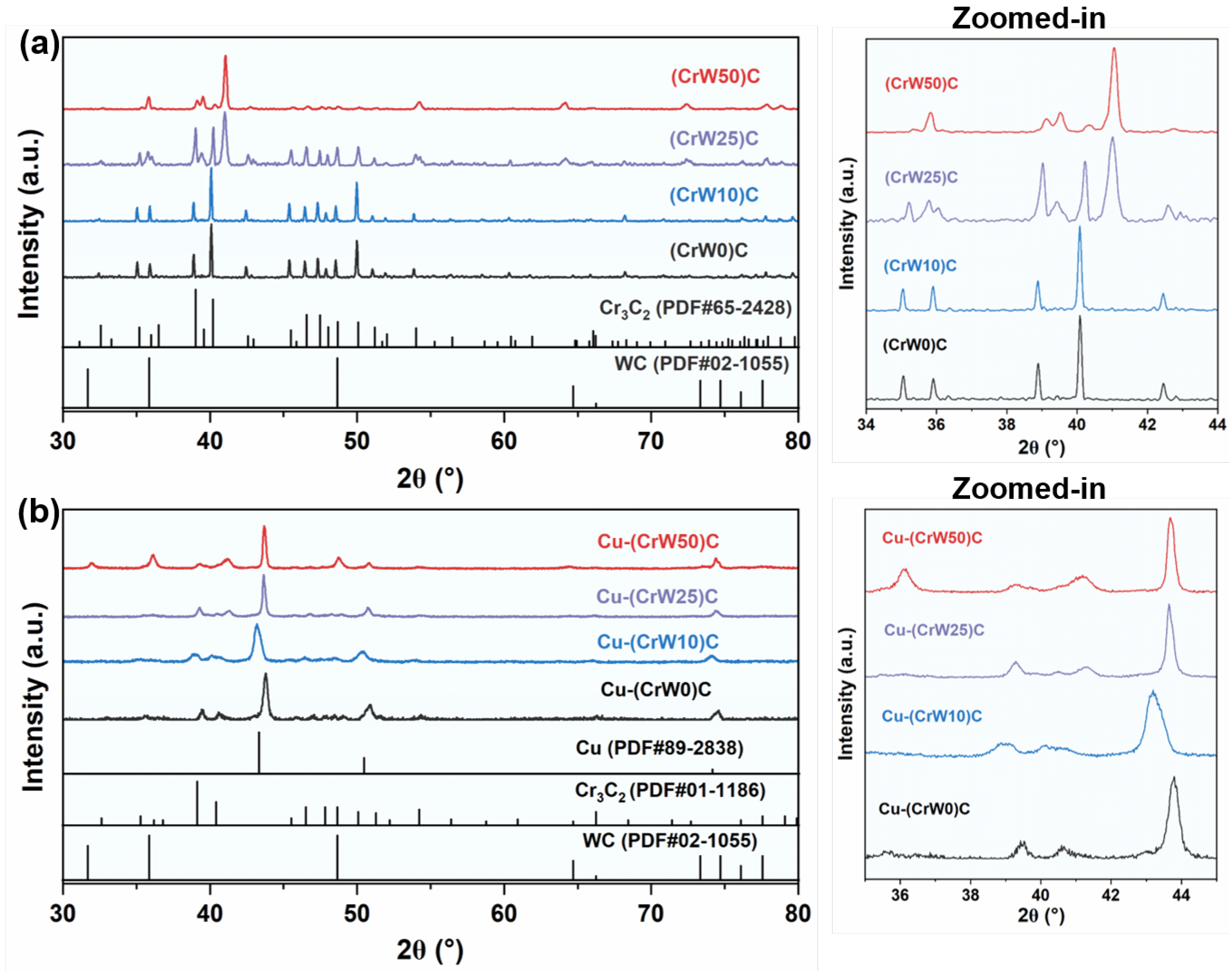
Figure 2.
SEM images and EDS elemental maps of (CrWₓ)C preforms with different W contents, showing the interconnected porous carbide skeleton and W-rich regions.
Figure 2.
SEM images and EDS elemental maps of (CrWₓ)C preforms with different W contents, showing the interconnected porous carbide skeleton and W-rich regions.
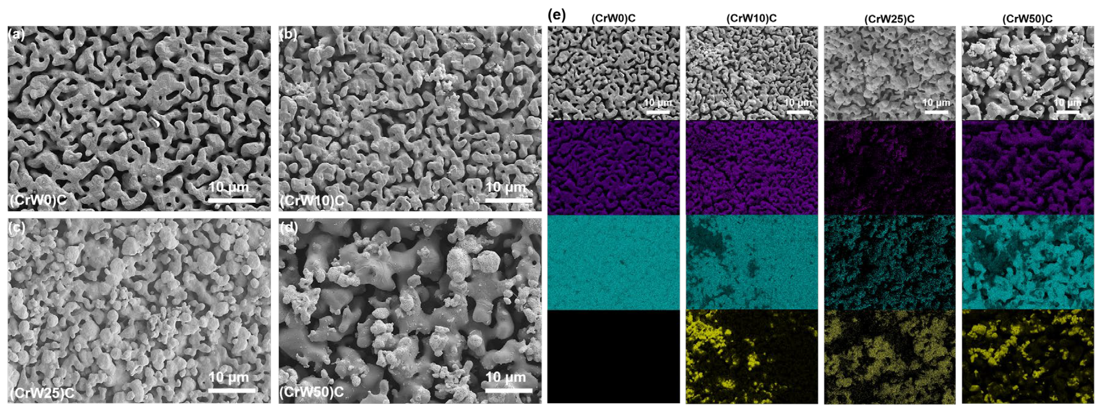
Figure 3.
SEM images and EDS elemental maps of Cu-(CrWₓ)C IPCs, showing the interpenetrating Cu-rich phase and Cr-W-C carbide skeleton.
Figure 3.
SEM images and EDS elemental maps of Cu-(CrWₓ)C IPCs, showing the interpenetrating Cu-rich phase and Cr-W-C carbide skeleton.
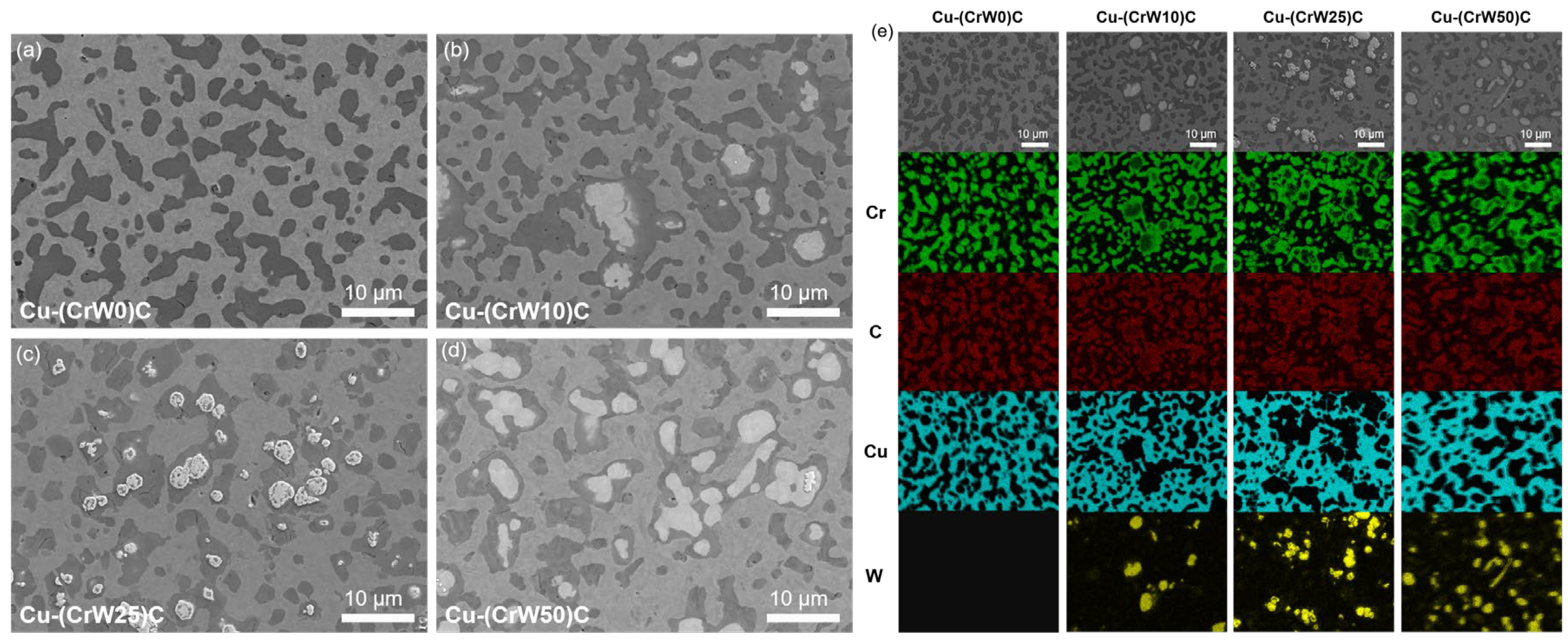
Figure 4.
Quasi-static compressive stress-strain curves of Cu-(CrWₓ)C IPCs at a strain rate of 0.001 s⁻¹, showing the large-strain load-bearing response of the interpenetrating Cu/carbide architecture.
Figure 4.
Quasi-static compressive stress-strain curves of Cu-(CrWₓ)C IPCs at a strain rate of 0.001 s⁻¹, showing the large-strain load-bearing response of the interpenetrating Cu/carbide architecture.
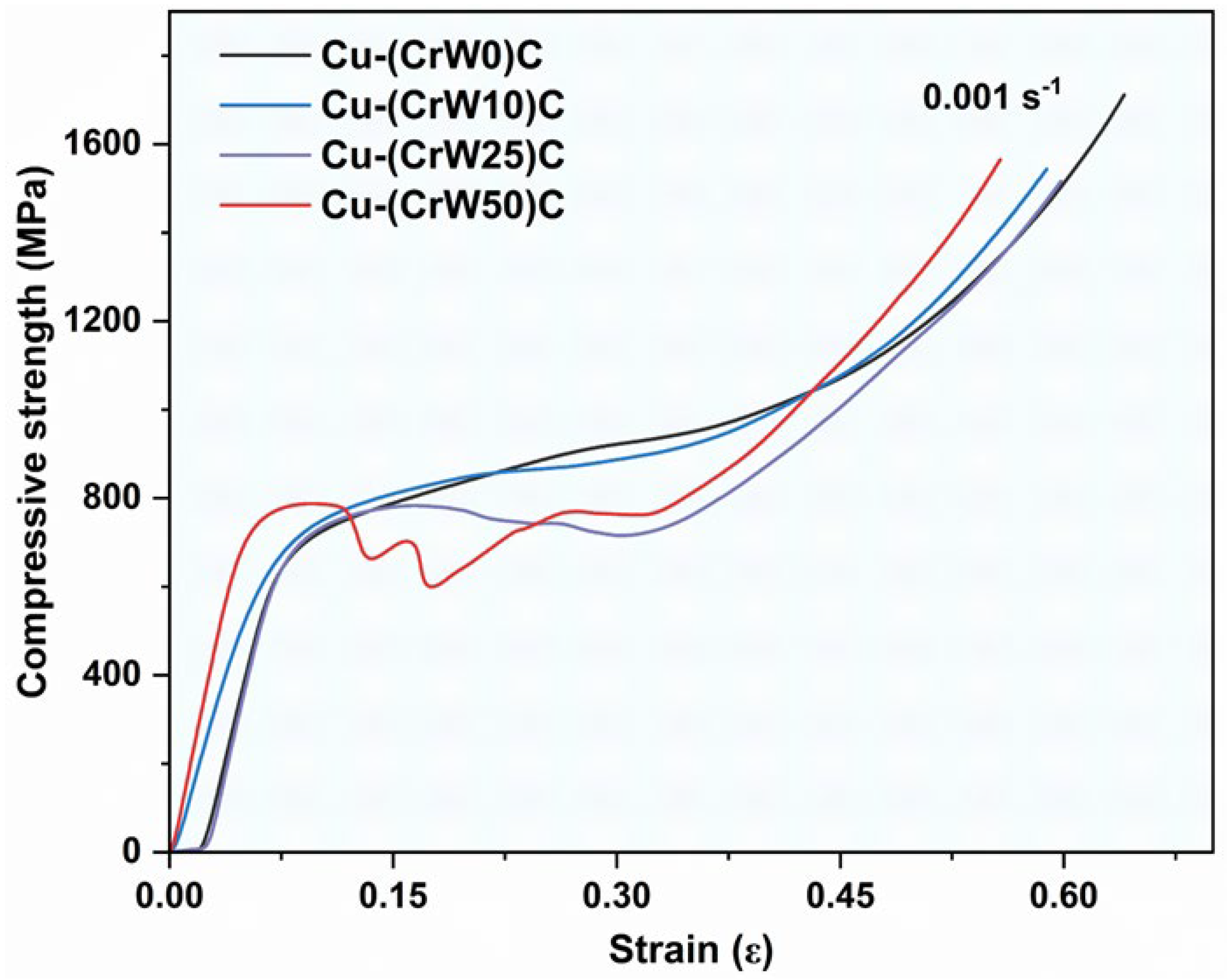
Figure 5.
Thermophysical and electrical properties of Cu-(CrWₓ)C IPCs: (a) room-temperature electrical conductivity, (b) thermal conductivity as a function of temperature, (c) thermal-expansion curves referenced to 30 °C, (d) average coefficient of thermal expansion from 30 to 500 °C, (e) thermal stability index defined as λ₅₀₀/α₃₀–₅₀₀, and (f) transport consistency factor ηTC between the measured room-temperature thermal conductivity and the electronic thermal conductivity estimated from the corrected electrical conductivity.
Figure 5.
Thermophysical and electrical properties of Cu-(CrWₓ)C IPCs: (a) room-temperature electrical conductivity, (b) thermal conductivity as a function of temperature, (c) thermal-expansion curves referenced to 30 °C, (d) average coefficient of thermal expansion from 30 to 500 °C, (e) thermal stability index defined as λ₅₀₀/α₃₀–₅₀₀, and (f) transport consistency factor ηTC between the measured room-temperature thermal conductivity and the electronic thermal conductivity estimated from the corrected electrical conductivity.
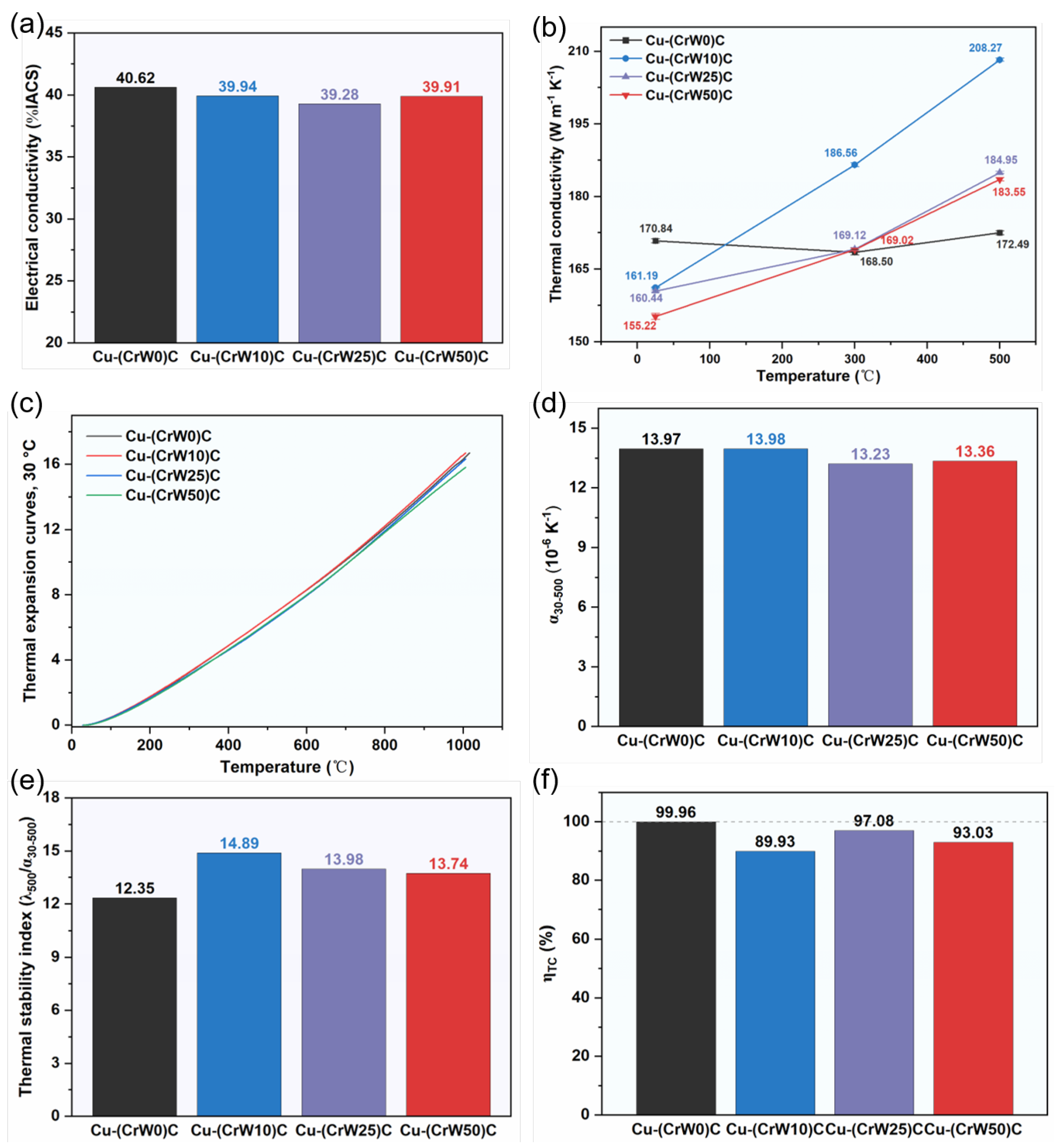
Figure 6.
Friction and wear behavior of Cu-(CrWₓ)C IPCs: (a) average and steady-state friction coefficients, (b) specific wear rate, and (c) COF-time curves. The steady-state COF was calculated for t ≥ 250 s.
Figure 6.
Friction and wear behavior of Cu-(CrWₓ)C IPCs: (a) average and steady-state friction coefficients, (b) specific wear rate, and (c) COF-time curves. The steady-state COF was calculated for t ≥ 250 s.
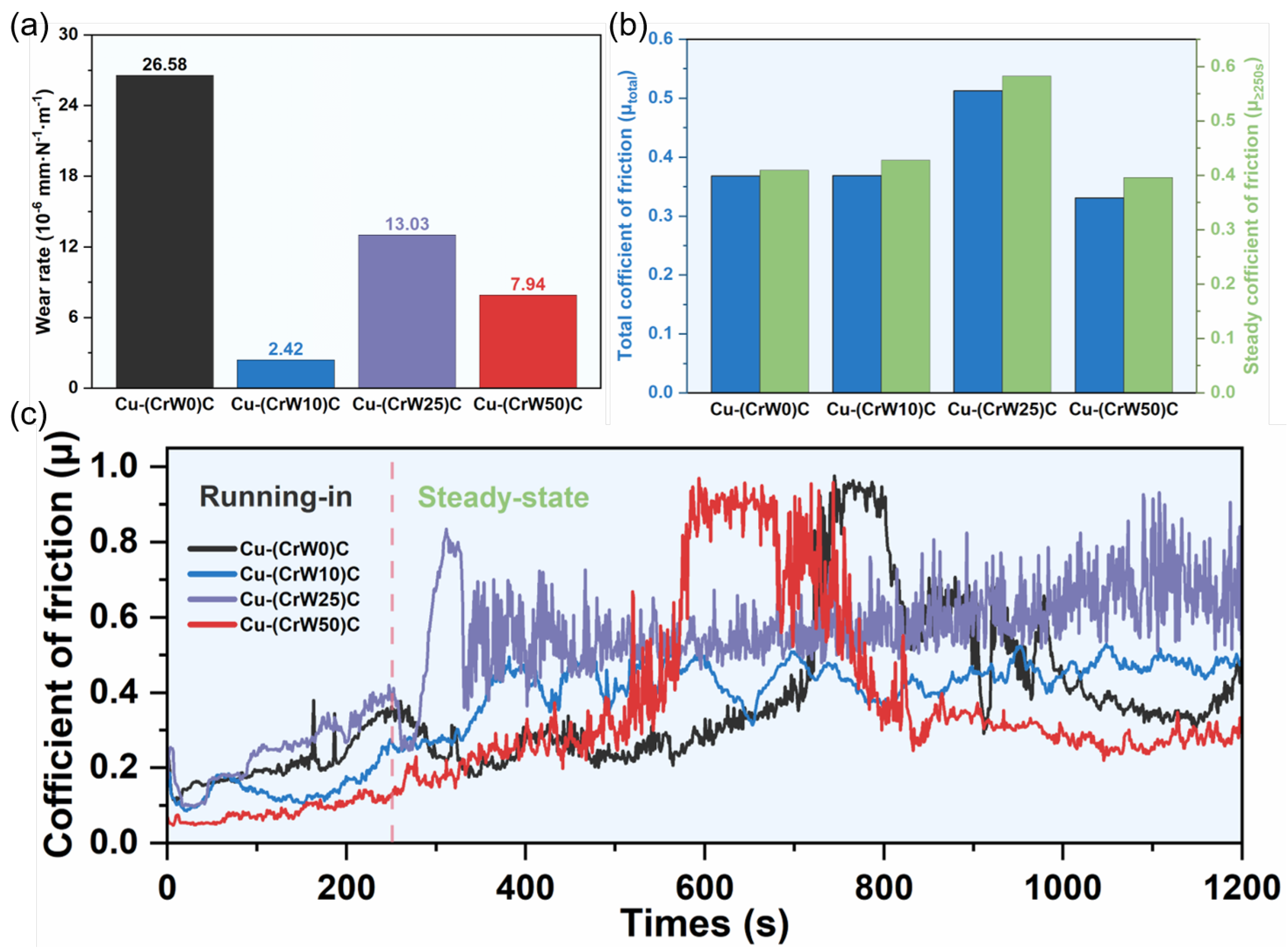
Figure 7.
Worn-surface morphologies of Cu-(CrWₓ)C IPCs after sliding wear: (a-d) low-magnification SEM images showing wear-scar widths and (e-h) high-magnification SEM images showing wear debris, ploughing grooves, and local cracks.
Figure 7.
Worn-surface morphologies of Cu-(CrWₓ)C IPCs after sliding wear: (a-d) low-magnification SEM images showing wear-scar widths and (e-h) high-magnification SEM images showing wear debris, ploughing grooves, and local cracks.
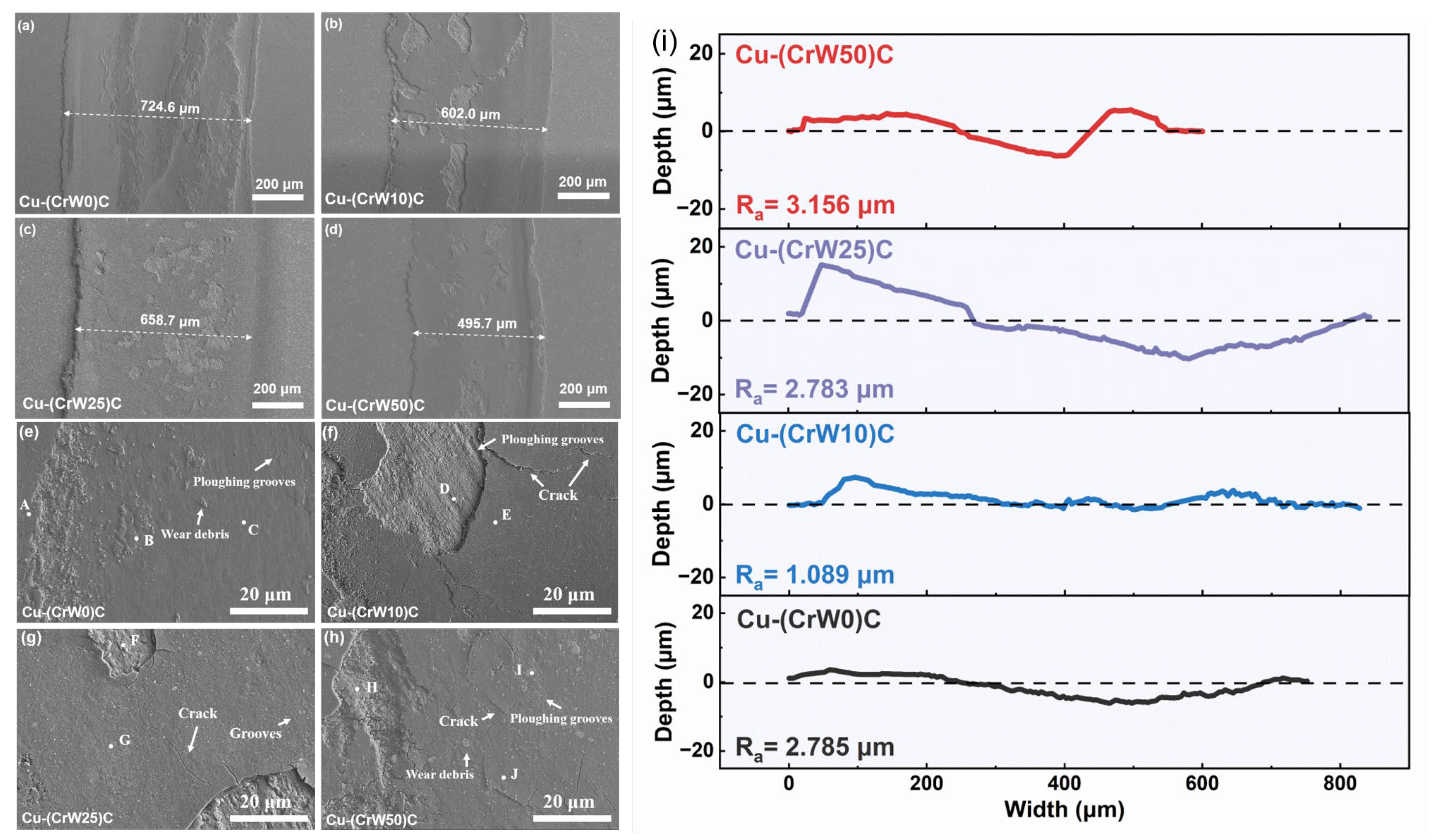
Figure 8.
EDS elemental mappings of worn surfaces of Cu-(CrWₓ)C IPCs after sliding wear, showing the distributions of Cu, Cr, W, C, and O in the tribo-damaged regions. The corresponding EDS point-scan results are provided in the Supplementary Information.
Figure 8.
EDS elemental mappings of worn surfaces of Cu-(CrWₓ)C IPCs after sliding wear, showing the distributions of Cu, Cr, W, C, and O in the tribo-damaged regions. The corresponding EDS point-scan results are provided in the Supplementary Information.
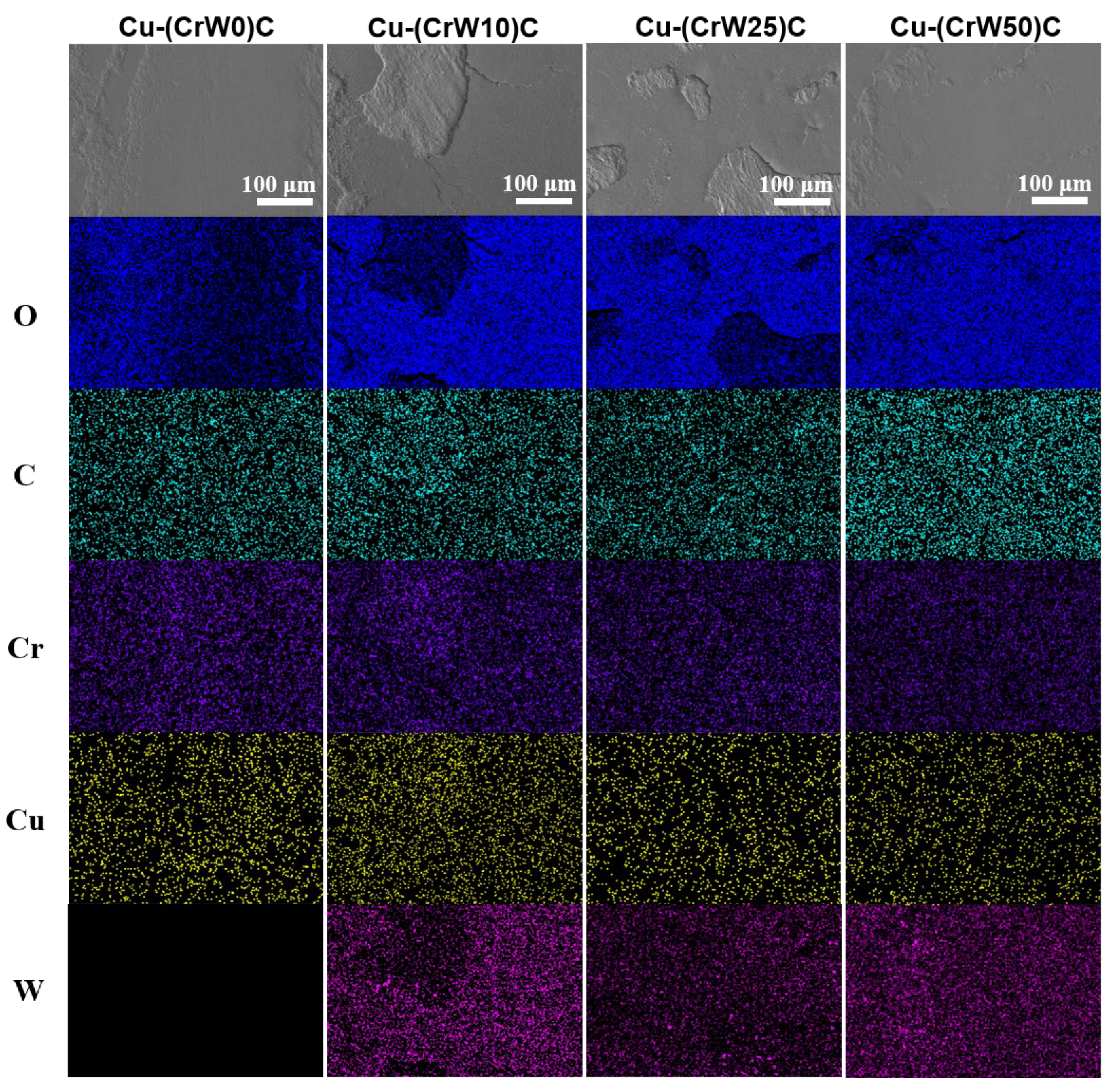
Figure 9.
Cross-sectional SEM images of worn scars of (a) Cu-(CrW0)C, (b) Cu-(CrW10)C, (c) Cu-(CrW25)C, and (d) Cu-(CrW50)C after sliding wear. The dashed lines indicate the worn surfaces. The marked features reveal tribo-damaged layers, interfacial debonding, subsurface cracks, carbide fragmentation, delamination cracking, plastic deformation traces, and local W-rich skeleton exposure.
Figure 9.
Cross-sectional SEM images of worn scars of (a) Cu-(CrW0)C, (b) Cu-(CrW10)C, (c) Cu-(CrW25)C, and (d) Cu-(CrW50)C after sliding wear. The dashed lines indicate the worn surfaces. The marked features reveal tribo-damaged layers, interfacial debonding, subsurface cracks, carbide fragmentation, delamination cracking, plastic deformation traces, and local W-rich skeleton exposure.
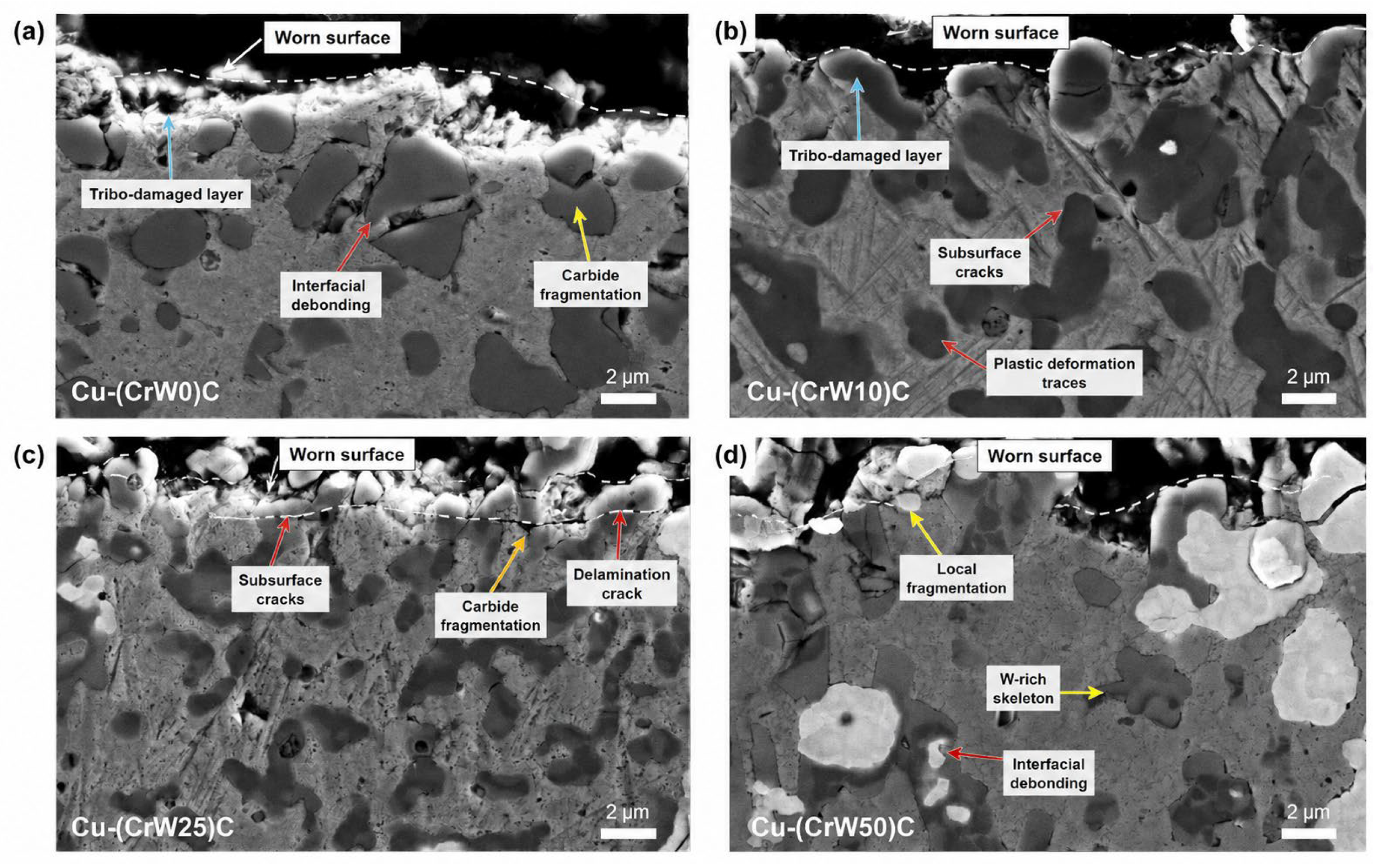
Figure 10.
Quantitative thermo-tribological coupling performance of Cu-(CrWₓ)C IPCs, including specific wear rate, wear loss per unit frictional work, thermal conductivity at 500 °C, and normalized TTPI.
Figure 10.
Quantitative thermo-tribological coupling performance of Cu-(CrWₓ)C IPCs, including specific wear rate, wear loss per unit frictional work, thermal conductivity at 500 °C, and normalized TTPI.
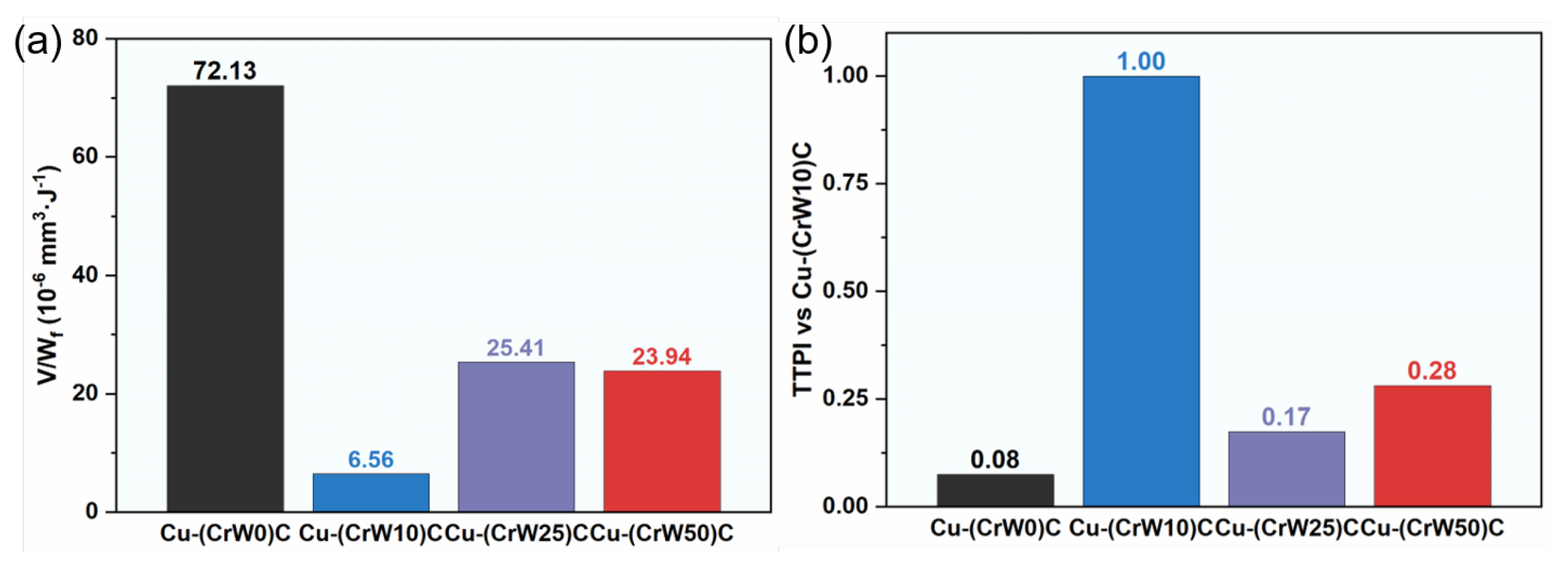
Figure 11.
Performance positioning and electrical-thermal-wear balance of Cu-(CrWₓ)C IPCs: (a) hardness-specific wear-rate map versus reported W-Cu-based wear-resistant materials, with the inset showing HV0.1 hardness with error bars; (b) ETWBI of the present IPCs, calculated from normalized terms representing thermal conductivity, electrical conductivity, wear resistance, and thermal-expansion stability. The literature data in Figure 11a correspond to Refs. [30,31,32,33,34,35,36]. The literature map is intended for performance positioning rather than direct ranking because wear rates depend on testing conditions.
Figure 11.
Performance positioning and electrical-thermal-wear balance of Cu-(CrWₓ)C IPCs: (a) hardness-specific wear-rate map versus reported W-Cu-based wear-resistant materials, with the inset showing HV0.1 hardness with error bars; (b) ETWBI of the present IPCs, calculated from normalized terms representing thermal conductivity, electrical conductivity, wear resistance, and thermal-expansion stability. The literature data in Figure 11a correspond to Refs. [30,31,32,33,34,35,36]. The literature map is intended for performance positioning rather than direct ranking because wear rates depend on testing conditions.
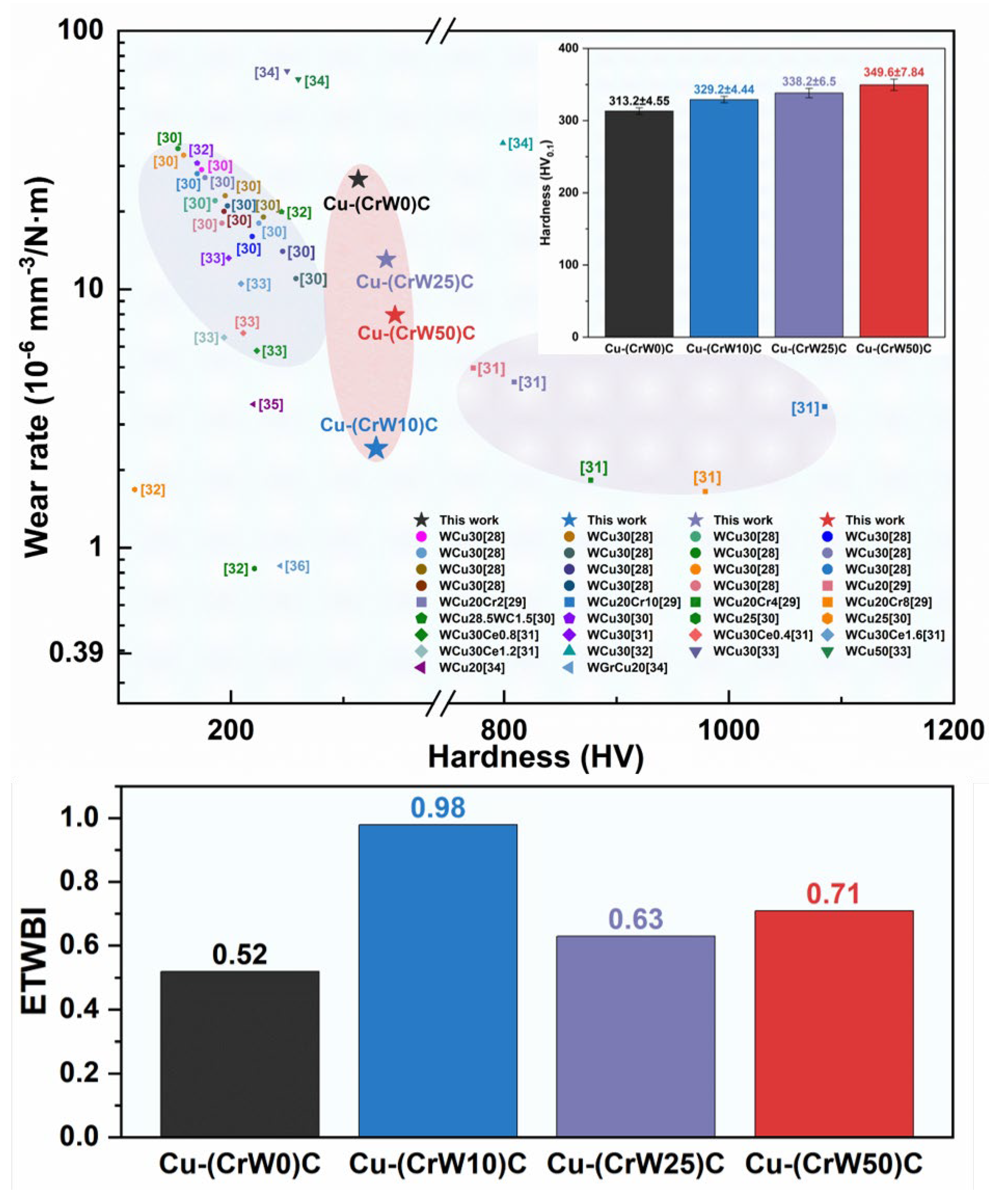

Table 1.
Key thermo-tribological coupling indicators of Cu-(CrWₓ)C IPCs.
| Sample | K | K_E | λ₅₀₀ | α₃₀–₅₀₀ | H | Πth | TTPI |
| Cu-(CrW0)C | 26.58 | 72.13 | 172.49 | 13.97 | 3.76 | 52.51 | 0.076 |
| Cu-(CrW10)C | 2.42 | 6.56 | 208.27 | 13.98 | 3.12 | 43.61 | 1.000 |
| Cu-(CrW25)C | 13.03 | 25.41 | 184.95 | 13.23 | 4.88 | 64.52 | 0.174 |
| Cu-(CrW50)C | 7.94 | 23.94 | 183.55 | 13.36 | 3.18 | 42.45 | 0.281 |
Notes: K is reported in 10⁻⁶ mm³ N⁻¹ m⁻¹; K_E is reported in 10⁻⁶ mm³ J⁻¹; λ₅₀₀ is reported in W m⁻¹ K⁻¹; α₃₀–₅₀₀ is reported in 10⁻⁶ K⁻¹; H and Πth are reported as 10⁻³; TTPI values are normalized by the value for Cu-(CrW10)C.
Disclaimer/Publisher’s Note: The statements, opinions and data contained in all publications are solely those of the individual author(s) and contributor(s) and not of MDPI and/or the editor(s). MDPI and/or the editor(s) disclaim responsibility for any injury to people or property resulting from any ideas, methods, instructions or products referred to in the content. |
© 2026 by the authors. Licensee MDPI, Basel, Switzerland. This article is an open access article distributed under the terms and conditions of the Creative Commons Attribution (CC BY) license.
Copyright: This open access article is published under a Creative Commons CC BY 4.0 license, which permit the free download, distribution, and reuse, provided that the author and preprint are cited in any reuse.


