
Submitted:
12 July 2026
Posted:
14 July 2026
You are already at the latest version
Abstract
Ammonia, as a hydrogen carrier and carbon-free alternative fuel, shows great potential in future low-carbon energy systems. This study uses dimethyl ether (DME) as a combustion promoter for ammonia to enhance the combustion performance of ammonia-fueled engines. To address the issue of unburned ammonia emissions, the original combustion chamber geometry was optimized by removing the squish area to enhance flame propagation. At an ammonia energy ratio (AER) of 60%, the modified combustion chamber (MCC) reduces unburned ammonia (uNH3) emissions by up to 85.46% and improves indicated thermal efficiency (ITE) by 1.93% compared to the original combustion chamber (OCC). Furthermore, to achieve higher thermal efficiency and lower pollutant emissions, the DME injection strategy was redesigned based on the MCC. The results show that adjusting the single injection timing (SIT) and injection angle (INA) of DME can effectively improve the homogeneity of the in-cylinder combustible mixture and enhance combustion efficiency; however, overly concentrated injection can lead to rapid heat release and increase the risk of knock. The split injection strategy enables more controllable combustion phasing, significantly reduces the maximum pressure rise rate (MPRR) and ringing intensity (RI), and mitigates knocking tendency. When the main injection timing (MIT) is −5 °CA ATDC, pilot injection timing (PIT) is −30 °CA ATDC, and the pilot injection ratio (PIR) is 60%, the ITE reaches 49.98%, which is 3.53% higher than that of the pure diesel mode. Greenhouse gas (GHG) and NOx emissions are reduced by 45.94% and 62.49%, respectively, with uNH3 emissions as low as 4.16 g/kw·h.
Keywords:
ammonia–dimethyl ether dual-fuel engines
; combustion chamber geometry
; injection strategy
; indicated thermal efficiency
; greenhouse gas
1. Introduction
In response to the energy transition and carbon neutrality goals, the development of low-/zero-carbon fuels and high-efficiency clean combustion strategies has become a key focus in the field of internal combustion engine research. Hydrogen has excellent combustibility and low ignition energy, and its complete combustion yields only water, meeting the requirements of low-carbon and environmentally friendly combustion. As a result, it has attracted widespread attention in the combustion research community [1]. However, hydrogen as a fuel still faces numerous challenges in production, storage, and transportation [2]. In contrast, ammonia, another carbon-free clean energy source, is considered a more promising carbon-neutral fuel due to its high energy density, ease of liquefaction, low production cost, and convenient storage and transportation. However, the slow combustion speed and low reactivity of ammonia present significant challenges when used as a sole fuel in engines [3]. To improve the combustion characteristics of NH3 and achieve stable and efficient combustion in compression ignition (CI) engines, reactive additives are commonly introduced to enhance its reactivity. In recent years, extensive research has been conducted on ammonia co-firing with various fuels.
Wen et al. [4] experimentally mixed ammonia with biomass-derived syngas (biosyngas) to enhance its reactivity and analyzed the reaction pathways of NH3 to reduce NOX emissions. Shrestha et al. [5] found that increasing the hydrogen content or enriching the oxygen concentration in the mixture can effectively enhance the laminar burning velocity, with the effect of adding 9% oxygen being equivalent to that of adding 30% hydrogen. Okafor et al. [6] extensively measured the laminar burning velocity of NH3/CH4 mixtures under high pressure and found that the velocity decreases with increasing ammonia concentration and pressure.
As shown in Table 1 [7,8,9], compared to other fuels, dimethyl ether (DME) is a clean fuel second only to hydrogen, with a high cetane number and diverse sources, making it an excellent fuel additive [10].
In addition, another advantage of DME is that it is non-toxic, non-mutagenic, and non-carcinogenic, with an extremely short atmospheric lifetime of less than one week and a global warming potential (GWP) as low as approximately 1 [11,12]. Gross C.W. [13] and Ryu K. [14] experimentally demonstrated that blending DME significantly promotes the combustion of ammonia fuel. However, under lean combustion and high ammonia energy ratio conditions for emission control, the ignition timing becomes increasingly difficult to stabilize, leading to poorer combustion consistency. Li et al. [15] used numerical simulations to investigate the effects of ammonia energy ratio (AER), DME injection timing, and ammonia injection pressure on the performance of a direct-injection ammonia/DME marine engine. The results showed that advancing the DME injection timing appropriately and increasing the liquid ammonia injection pressure can effectively reduce NOx emissions and improve thermal efficiency.
It is worth noting that in-cylinder direct injection of ammonia faces challenges such as ignition difficulty, unstable combustion, and complex injection systems [16], making it difficult to achieve efficient and reliable combustion. In contrast, introducing ammonia through the intake port allows the formation of a well-premixed charge, which helps stabilize combustion and simplifies system design. However, introducing ammonia via the intake manifold can lead to significant fuel slip, resulting in severely reduced combustion efficiency. Moreover, as a toxic gas, ammonia poses a serious risk to human health and life when its concentration exceeds 300 ppm [17]. In internal combustion engine design, an appropriately shaped combustion chamber can significantly enhance combustion quality [18]. This is particularly important for ammonia, which has low reactivity; optimizing the combustion chamber shape based on dual-fuel combustion processes and flame propagation paths is considered one of the most effective strategies to reduce unburned ammonia emissions [19,20]. In addition, optimizing the injection strategy can further reduce pollutant emissions and improve thermal efficiency [21].
Liu et al. [22] employed numerical simulations and a genetic algorithm to perform multi-objective optimization of the combustion chamber geometry (CCG) in a diesel/natural gas dual-fuel engine. The results showed that a straight-line combustion chamber could effectively reduce CH4 emissions, achieving an indicated thermal efficiency (ITE) as high as 50.2% when the injection timing was set to -16.45 °CA ATDC. Ye et al. [23] investigated the effects of several common CCGs on combustion and flame propagation characteristics in ammonia–diesel dual-fuel (ADDF) engines. They found that stronger reverse squish enhanced fuel diffusion in the squish regions of the original combustion chamber (OCC), petal-type combustion chamber (PTCC), and shallow-depth combustion chamber (SCC). In the case of the toroidal combustion chamber (TCC), stronger swirl motion significantly improved diffusion combustion. Shi et al. [24] calibrated their simulation model based on the experimental data from Yousefi et al. [25], and then optimized the diesel injection timing and injection angle at a 40% ammonia energy ratio (AER) to improve thermal efficiency. The optimal configuration reduced unburned ammonia emissions to as low as 0.279 g/kw·h. However, the stability and reliability of the engine under actual operating conditions have not been fully considered. Similarly, Shin et al. [21] optimized diesel injection timing under various AERs and showed that, compared with the pure diesel mode, advancing the injection timing at high AER significantly reduced greenhouse gas (GHG) emissions by up to 80.6%. Mi et al. [26] experimentally demonstrated that a split injection strategy enables stable combustion and GHG reduction over a wide AER range in ADDF engines; however, it inevitably leads to higher NOX, CO, and unburned hydrocarbon (uHC) emissions.
In summary, employing ammonia introduced through the intake port combined with direct injection of DME into the cylinder in a CI engine can fully leverage ammonia’s zero-carbon emissions and DME’s low-carbon, high-reactivity advantages as a mixed fuel. However, current research on ammonia/DME dual-fuel combustion primarily emphasizes fundamental combustion characteristics and chemical kinetics, while studies that explore the adaptation of injection strategies to specific combustion chamber geometries remain scarce. In a recent study [27], we optimized the original combustion chamber geometry under the ADME-DF mode based on dual-fuel combustion characteristics by eliminating the squish region to enhance flame propagation, aiming to reduce unburned ammonia (uNH3) and greenhouse gas (GHG) emissions while improving combustion efficiency. The results showed that the modified combustion chamber (MCC) reduced uNH3 emissions by up to 85.46% and increased the indicated thermal efficiency (ITE) by 1.93% compared to the original combustion chamber (OCC). However, due to the lack of corresponding adjustments to the injection strategy in the new combustion chamber, combustion and emission performance under high ammonia energy ratios (AER) were inferior to those of the OCC. To address these issues, this study optimized the DME injection strategy based on the newly designed combustion chamber by adjusting the injection nozzle angle (INA) and single injection timing (SIT) for single injection, as well as the pilot injection timing (PIT) and pilot injection ratio (PIR) for split injection, aiming to further reduce uNH3 and greenhouse gas (GHG) emissions in the ADME-DF mode while ensuring stable operation and achieving high thermal efficiency.
2. Materials and Methods
2.1. Model Development
The engine model used in this study is a four-stroke, single-cylinder compression ignition (CI) engine, with the basic parameters listed in Table 2. To reduce computational cost, a one-seventh sector model of the engine was constructed by utilizing the symmetry of the original combustion chamber (OCC). The simulation starts at the intake valve closing and ends at the exhaust valve opening.
The RNG k-ε model [28] was employed to predict the complex in-cylinder turbulence. The KH-RT model [29] was used to characterize the primary and secondary breakup of spray droplets, while the Frossling model [30] was applied to simulate droplet evaporation. The NTC model [31] was adopted to model droplet collisions. Wall heat transfer was calculated using the model developed by O’Rourke and Amsden [32]. In addition, the SAGE detailed chemical kinetics solver [33] was employed to simulate the combustion process inside the chamber. NOx emissions were predicted using the extended Zeldovich mechanism [34]. Table 3 lists the sub-models used in the simulation. The selection of an appropriate combustion mechanism is crucial for the numerical simulation of engine combustion processes. The comprehensive detailed mechanism for ammonia/DME combustion developed by Yin et al. [35], based on the mechanisms proposed by Hashemi et al. [36] and Zhang et al. [37], includes 193 species and 1669 reactions, and has been validated against experimental data reported in the literature [5,38]. The base mesh size was set to 2 mm, with three levels of mesh refinement applied in the fuel injection region. In addition, adaptive mesh refinement (AMR) was employed based on temperature and velocity gradients to ensure computational accuracy. The main boundary conditions used in the simulation are summarized in Table 4.
2.2. Definition of Relevant Characteristic Parameters
In this study, the apparent heat release rate (AHRR) was calculated using cylinder volume and in-cylinder pressure according to Equation (1), where is the in-cylinder pressure, is the cylinder volume, is the crank angle, and is the ratio of specific heats.
CA10, CA50, and CA90 correspond to the crank angle positions at which 10% (start of combustion), 50% (location of heat release centroid), and 90% (end of combustion) of the cumulative heat release from in-cylinder dual-fuel combustion occurs, respectively. The ignition delay and combustion duration are defined as the time intervals SOI–CA10 and CA10–CA90, respectively.
The ammonia energy ratio (AER) is calculated according to Equation (2), where denotes the proportion of energy contributed by ammonia. represents the total mass of ammonia injected per cycle, denotes the mass of dimethyl ether (DME) injected per cycle, and and are the lower heating values of DME and ammonia, respectively.
The formulas for calculating indicated thermal efficiency (ITE) and unburned energy losses are given by Equations (3) and (4), respectively. In these equations, refers to the indicated work per engine cycle. and represent the masses of unburned NH3, DME, HC, and CO, respectively. and denote the lower heating values of HC and CO, respectively.
A specific resonant frequency generated within the cylinder produces high-intensity pressure waves, referred to as ringing intensity (RI), which can be used to evaluate the engine’s knocking tendency [39]. RI reflects the maximum pressure rise rate (MPRR) and can be calculated using Equation (5), where γ is the ratio of specific heats; represents the engine’s maximum pressure rise rate (MPRR); is the universal gas constant; and is a coefficient derived from pressure oscillations, typically taken as 0.05 ms [40]. and denote the maximum in-cylinder pressure and temperature, respectively.
2.3. Model Validation
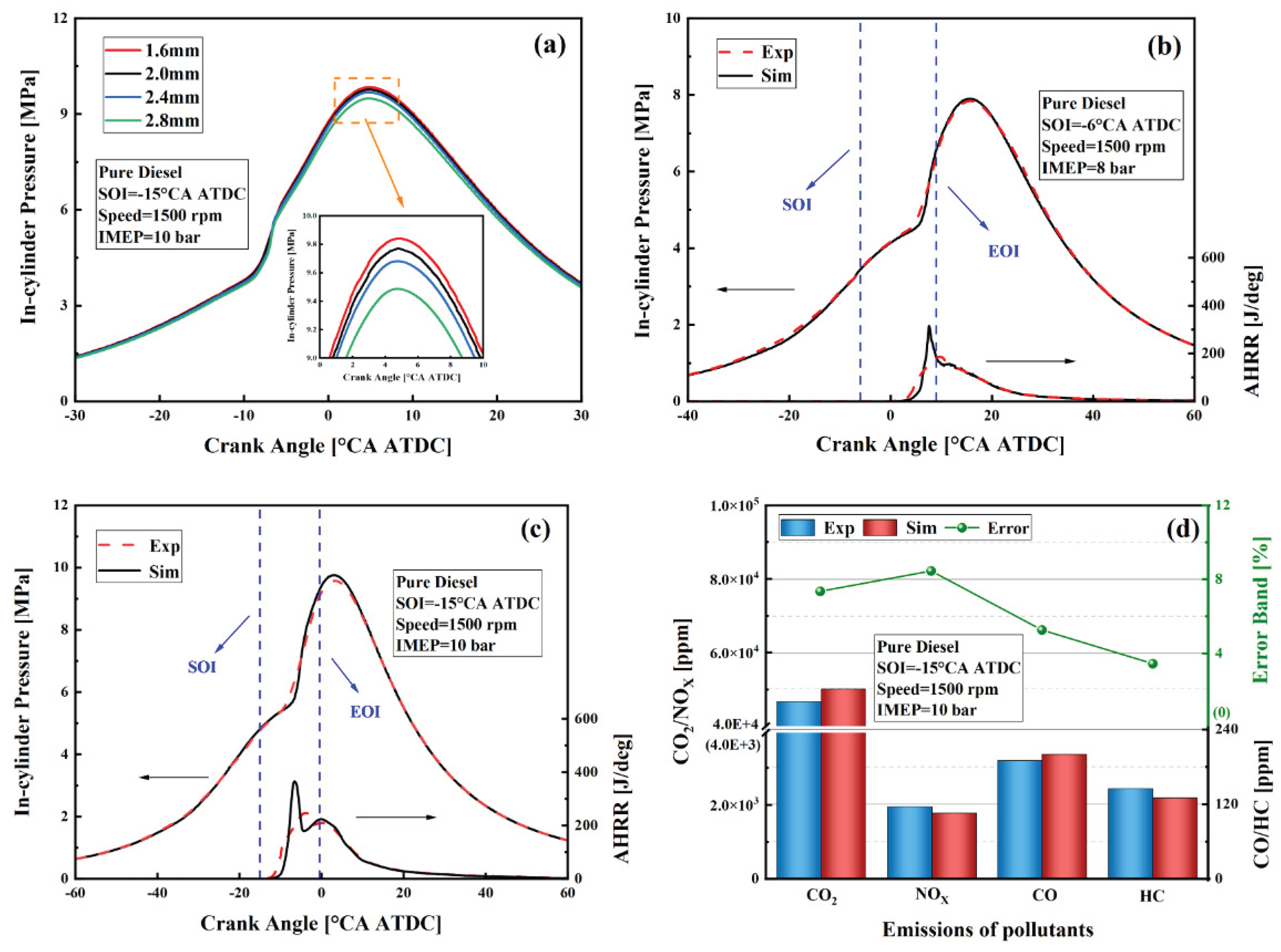
To ensure the accuracy of the CFD simulation results, the present study validated the model using experimental data for pure diesel combustion reported by Jin et al. [41]. The surrogate diesel mechanism was based on the n-dodecane skeletal mechanism developed by Frassoldati et al. [42], which includes 96 species and 993 reactions. Prior to the simulation, a grid independence study was conducted. As shown in Figure 2(a), the in-cylinder pressure curve obtained with a 2.8 mm grid exhibited noticeable deviations. No significant differences were observed among the results obtained with grid sizes of 1.6 mm, 2.0 mm, and 2.4 mm. Therefore, a grid size of 2.0 mm was selected as a compromise between computational accuracy and efficiency.
Figure 2(b) and (c) compare the simulated and experimental in-cylinder pressure and heat release rate (HRR). The simulated in-cylinder pressure agrees well with the experimental data, while some discrepancies are observed in the HRR curves. These differences are primarily attributed to the use of a sector mesh model [43], as well as variations in cetane number and heating value between real diesel and n-dodecane. Furthermore, the neglect of wall heat transfer losses in the simulation contributes to an overprediction of the HRR peak compared to the experimental measurements [44]. Figure 2(d) presents a comparison of key pollutant emissions, with all discrepancies remaining within 8.5%. In summary, the developed simulation model is reliable and provides a solid foundation for future studies on engine performance optimization and emission control strategies.
Figure 1.
Model validation: (a) grid independence verification; (b,c) in-cylinder pressure and AHRR; (d) major emissions.
Figure 1.
Model validation: (a) grid independence verification; (b,c) in-cylinder pressure and AHRR; (d) major emissions.
2.4. Selected Simulation Cases
The geometry of the combustion chamber significantly influences in-cylinder flow characteristics and flame propagation, particularly in ADME-DF engines. To enhance combustion efficiency and reduce pollutant emissions, the combustion chamber geometry (CCG) should be optimized based on the properties of the fuels and the combustion process. As shown in Figure 2(c), for the original combustion chamber (OCC), a squish region is formed between the piston crown and cylinder head when the piston reaches top dead center (TDC). This squish region adversely affects the distribution of ammonia fuel and flame propagation in the cylinder, thereby reducing combustion efficiency and increasing emissions. To mitigate these issues, this study proposes a modification to the OCC. The squish region is removed while maintaining the same combustion chamber volume, aiming to improve flame propagation and reduce uNH3 emissions.
Due to the influence of combustion chamber geometry on mixture formation, flame propagation, and the local combustion environment, an optimized injection strategy is necessary to achieve more complete combustion, higher thermal efficiency, and lower emissions. In addition, when DME is used as an alternative fuel in CI engines, its lower heating value and density compared to diesel typically require increasing the injection pressure, nozzle diameter, or the number of nozzle holes. However, using a small amount of DME can also simplify the modification of fuel injection systems [45,46]. Therefore, in this study, based on the MCC, a constant DME injection pressure of 300 bar and an AER of 60% were adopted. For the single injection strategy, the injection nozzle angle (INA) was varied from 55° to 85°, and the single injection timing (SIT) was varied from -35 °CA ATDC to -10 °CA ATDC. For the split injection strategy, the main injection timing (MIT) was fixed at -5 °CA ATDC, while the pre-injection ratio (PIR) was varied from 20% to 80%, and the pre-injection timing (PIT) from -70 °CA ATDC to -30 °CA ATDC. The effects of injection strategies on the performance of the ADME-DF engine were systematically investigated. Detailed injection strategies are shown in Table 5.
3. Results and Discussion
3.1. Effects of AER and CCG on the Performance of ADME-DF Engines
The effects of Ammonia Energy Ratio (AER) and Combustion Chamber Geometry (CCG) on the ADME-DF engine have been investigated in our previous work [27], and are revisited here for completeness. Figure 3(a) and (b) compare in-cylinder pressure, HRR, and combustion phasing under different AERs for the OCC and MCC. It can be observed that the combustion characteristics under varying AERs are similar for both CCGs. Specifically, the decreases with increasing AER, while the peak HRR initially increases and then decreases, reaching its maximum at an AER of 60%. The gradual decrease in with higher AER is primarily attributed to the slower combustion rate and lower reactivity of ammonia. Replacing part of the DME with ammonia reduces the overall combustion rate, leading to delayed combustion and reduced peak pressure. The initial increase and subsequent decrease in HRR peak with rising AER can be explained by the enhanced combustion intensity in the low AER range, where DME promotes ammonia ignition. However, when the AER exceeds 60%, the limited DME content becomes insufficient to sustain strong flame propagation and ignition enhancement, leading to reduced combustion efficiency and a decline in the HRR peak. In addition, under the ADME-DF mode, the combustion phasing in the MCC is consistently delayed compared to that in the OCC across various AERs. This can be partially attributed to the shallower combustion chamber in MCC, which causes the DME spray to impinge on the wall prematurely, resulting in kinetic energy loss and suboptimal initial fuel-air mixing. On the other hand, the removal of the squish region in MCC, though beneficial for promoting ammonia ignition, may also contribute to delayed combustion phasing.
Figure 3(c) and (d) illustrate the average in-cylinder temperature and indicated thermal efficiency (ITE) for OCC and MCC under various AERs. As AER increases, the overall combustion reactivity initially improves and then deteriorates, leading to the optimal heat release rate and concentration at an AER of 60%. Consequently, the peak in-cylinder temperature exhibits an initial rise followed by a decline. As shown in Figure 3(d), the MCC configuration achieves higher ITE than OCC within the AER range of 50%–70%, and also outperforms the conventional diesel mode. However, at an AER of 80%, MCC performs worse than OCC, with unburned energy losses reaching as high as 31.1%. This indicates that, without further optimization, the advantages of MCC remain limited under high AER conditions.
Figure 4(a) and (b) compare the final emissions of unburned energy loss-related species between OCC and MCC under different AERs. It can be observed that with increasing AER, the emissions of uDME and uNH3 increase, primarily due to the low reactivity of ammonia. At an AER of 60%, the uNH3 emission from MCC is only 4.16 g/kw·h, representing an 85.46% reduction compared to OCC. However, at an AER of 80%, the uNH3 emission of MCC reaches 148 g/kw·h, which is 38.3% higher than that of OCC. Since MCC eliminates the squish region present in OCC, it theoretically facilitates flame propagation and thus should reduce uDME and uNH3 emissions. However, maintaining the OCC volume necessitates a reduction in chamber depth in MCC, causing DME spray to impinge on the wall earlier, resulting in kinetic energy loss and poor initial dual-fuel mixing, which ultimately leads to higher uNH3 emissions at 80% AER compared to OCC. Similarly, at 80% AER, emissions of CO and unburned hydrocarbons (uHC), which contribute to minor energy losses, are also higher in MCC than in OCC. The decrease in in-cylinder temperature is the main reason for the increased CO emissions, while the DME impingement on the wall delays combustion and causes incomplete droplet evaporation, resulting in increased uHC emissions.
As shown in Figure 4(c), CO2 emissions gradually decrease with the reduction in DME injection quantity. N2O, which has a global warming potential up to 300 times greater than CO2, is mainly formed in regions of moderate to low temperature, oxygen deficiency, and partial oxidation of ammonia [47]. At an AER of 60%, MCC reduces GHG emissions by 14.8% compared to OCC. Due to the dominant magnitude of NO in total NOX emissions, NOX formation is primarily associated with NO. Unlike conventional diesel combustion, ammonia as a fuel contains nitrogen atoms, resulting in the formation of both thermal-NOX and fuel- NOX during the combustion process. Compared to OCC, the MCC design eliminates the squish region, allowing for more uniform flame propagation and reducing the occurrence of locally high-temperature, oxygen-rich zones. Consequently, NOx emissions from MCC are consistently lower than those from OCC [48].
Changes in CCG can significantly affect in-cylinder flow and the formation of combustible mixtures. Therefore, it is necessary to adjust the injection strategy accordingly, such as the injection angle and timing, to optimize the spray development and mixture uniformity of DME, ensure reliable ignition, promote efficient synergistic combustion, and reduce emissions.
3.2. Effects of SIT and INA on the Performance of the ADME-DF Engine
To fully exploit the potential of the MCC, this section investigates the effects of varying the single injection timing (SIT) and injection nozzle angle (INA) of DME at a constant 60% ammonia energy ratio (AER) to further improve combustion efficiency. Figure 5(a) and (b) compare in-cylinder pressure, HRR, and combustion phasing under different SITs and INAs in the single DME injection strategy. It is evident that advancing the DME injection timing raises the peak in-cylinder pressure and shortens the ignition delay time (IDT), which is attributed to improved fuel-air mixing. At an SIT of −15° CA ATDC, increasing the INA results in higher peak pressure and HRR. However, when the SIT is advanced to −30° CA ATDC, an INA of 85° results in a decrease in both pressure and HRR peaks. As shown in the inset of Figure 5(a), at an INA of 85°, the DME spray tends to impinge on the cylinder wall, whereas at other angles, the spray mainly strikes the piston bowl. As shown in Figure 5(b), in Case 1, increasing INA shortens the combustion duration. In contrast, in Strategy 2, an INA of 85° leads to an extended combustion duration.
As shown in Figure 5(c), under varying SITs, the in-cylinder temperature peak first increases and then decreases with increasing INA. In Case 1, the peak temperature starts to decline when the INA reaches 75°. In Case 2, the temperature peak drops at an INA of 85°. This indicates that as the injection timing advances, the INA corresponding to the peak temperature decline shifts to a larger angle. As shown in Figure 5(d), in Case 1, the maximum indicated thermal efficiency (ITE) of 48.65% occurs at an INA of 65°. In Case 2, the highest ITE of 49.86% is achieved at an INA of 75°, with an unburned energy loss of only 1.24%. This suggests that earlier injection timing is better matched with a larger INA.
To further analyze the effects of varying SITs and INAs on combustion and emissions, Figure 6(a) and (b) show longitudinal cross-sectional distributions of key parameters and species concentrations during the main combustion phase under different INAs for both cases. At an INA of 55°, the DME jet impinges on the piston bowl, travels along its edge, strikes the cylinder head, and finally disperses into the combustion chamber. At an INA of 85°, the DME spray is also influenced by the cylinder wall. When SIT is −15 °CA ATDC, the squish region formed by the piston and cylinder head enhances the rebound effect from wall impingement, promoting more uniform in-cylinder fuel mixing. However, at the same INA of 85°, when the SIT is advanced to −30 °CA ATDC, some DME droplets form a stagnant film on the wall surface, reducing their contribution to effective mixing and reaction in the main combustion zone. This results in slower late-stage combustion and a longer combustion duration.
The SIT and INA of DME influence both in-cylinder combustion performance and emissions. In the ADME-DF engine, NOX formation is a complex process. With a fixed AER of 60%, ammonia combustion efficiency directly affects fuel-NO formation, described by Equation (6), which primarily occurs at high combustion temperatures (T > 1400 K); Additionally, thermal-NOX formation is influenced by in-cylinder temperature, the spatial and temporal distribution of high-temperature regions, and oxygen concentration. Specifically, NH3 reacts with hydroxyl radicals (OH) and oxygen atoms to form NH2 radicals, and NO is subsequently reduced within the temperature range of 1100–1400 K [48]. This reaction pathway is illustrated by Equations (7)–(10) [49]. The in-cylinder temperature and NO distributions in Figure 6(a) and (b) illustrate the formation characteristics.
NHi + OX → NO + NHi
NH3 + OH → NH2 + H2O
NH3 + O → NH2 + OH
NH2 + NO → N2 + H + OH
NH2 + NO → N2 + H2O
As shown in Figure 6(a) and (b), in Case 1, uNH3 concentration is higher at an INA of 55° compared to other INAs, primarily distributed near the cylinder wall and cylinder head away from the center of the piston bowl. In Case 2, uNH3 is highest at an INA of 85°, with concentrations primarily located at the center of the piston bowl. This indicates that a proper combination of injection nozzle angle and timing can improve in-cylinder dual-fuel mixing, mitigate overly rich or lean regions. Furthermore, N2O, a product of incomplete ammonia combustion, primarily forms at the leading edge of the NH3 flame. Its formation pathway, described by Equations (10) and (11), primarily occurs at temperatures below 1400 K [50]. However, the figure does not clearly present a quantitative comparison of final emissions, such as NO and N2O, under different injection strategies.
NH + NO → N2O + H
NH2 + NO2 → N2O + H
As shown in Figure 7(a) and (b), advancing the injection timing lowers the in-cylinder temperature, promoting DME condensation on the piston and cylinder walls and forming a liquid film that hinders combustion, thereby increasing uDME emissions. Furthermore, in Case 1, an INA of 85° enhances DME ignition and ammonia reactivity, resulting in uNH3 emission of only 1.55 g/kw·h, a reduction of 62.74% compared to the original MCC injection strategy. Similarly, in Case 1, an INA of 65° results in CO and uHC emissions of 0.2 g/kw·h and 0.02 g/kw·h, respectively, representing reductions of 82.9% and 90.1% compared to the original strategy. As illustrated in Figure 7(c) and (d), the minimum GHG and NOX emissions occur at an INA of 65° in Case 2 and 75° in Case 1, respectively, corresponding to reductions of 54.8% and 86.1% compared to the conventional diesel mode. These minimum GHG and NOX values are primarily influenced by in-cylinder temperature, spray targeting, and mixture formation, underscoring the capability of injection strategies for precise multi-pollutant control.
To comprehensively reveal the coupled effects of SIT and INA on combustion and emission characteristics of the ADME-DF engine, Figure 8(a) and (b) present contour plots of uNH3 emissions and ITE under various DME injection timings and angles. Under an AER of 60%, elevated uNH3 emissions are concentrated in the central, upper-left, and lower-right regions of the figures. Specifically, with relatively advanced injection timings, larger INAs help reduce uNH3 emissions, whereas smaller angles are better suited to delayed injection timings. Additionally, when SIT is set to −10 °CA ATDC, the engine exhibits suboptimal combustion performance, with ITE remaining at a low level. This is primarily attributed to the insufficient mixing of NH3 and DME, which prolongs the combustion duration and reduces combustion efficiency.
Figure 8(c) and (d) illustrate the distributions of GHG and NOX emissions. In Figure 8(c), the variation in GHG emissions is primarily attributed to N2O, and a comparison with Figure 8(a) reveals similar spatial patterns. From a macroscopic perspective, N2O is a byproduct of incomplete NH3 combustion; therefore, elevated uNH3 emissions indicate inefficient NH3 oxidation, leading to increased N2O formation and degraded combustion performance. On a microscopic level, oxygen-deficient regions, combined with underdeveloped radical chain reactions, inhibit the complete conversion of NH3 to N2, favoring the formation of N2O as an intermediate product. Thus, increased uNH3 emissions not only reflect incomplete combustion but also signify low radical concentrations (e.g., O, H, OH), insufficient reaction chain propagation, and interrupted oxidation pathways, all of which promote N2O accumulation.
In Figure 8(d), within the range of relatively advanced SITs, NOX emissions increase with earlier injection, while the influence of INA is comparatively limited. However, when the SIT is advanced to −30 °CA ATDC, INA has a pronounced effect on NOX emissions. Given that the AER is fixed at 60%, NOx emissions are primarily governed by the formation of thermal-NOX. Typically, advancing the injection timing leads to more uniform fuel mixing, shortens both ignition delay time (IDT) and combustion duration (CD), and leads to a rapid increase in in-cylinder temperature, collectively contributing to elevated NOX emissions. Moreover, the combined variation of injection timing and angle alters the spray characteristics of DME, which also changes the wall-impingement timing and subsequently affects fuel mixing.
It is worth noting that in the practical application of ADME-DF engines, attention should not only be paid to combustion and emission characteristics, but also to the avoidance of abrupt in-cylinder pressure rise in order to reduce the risk of engine knock and ensure operational stability. As shown in Figure 9(a) and (b), it is difficult to meet the MPRR limitation and RI requirements solely by adjusting the injection nozzle angle or injection timing. MPRR typically occurs near CA10[21], and while the single injection strategy enhances engine performance by improving fuel mixing, it also concentrates the combustion of a large amount of fuel, causing a rapid rise in in-cylinder pressure and excitation of the natural frequency oscillations of the cylinder block and combustion chamber structure. Therefore, the next section will investigate the effects of a split injection strategy on ADME-DF engine performance, with the aim of ensuring engine reliability and durability.
3.3. Effects of Split Injection Strategy on the Performance of the ADME-DF Engine
The split injection strategy can optimizes the heat release process and controls the combustion rate by adjusting the pilot injection ratio (PIR), pilot injection timing (PIT), and main injection timing (MIT), thereby enhancing high thermal efficiency and reducing emissions while satisfying the maximum pressure rise rate (MPRR) constraints [26]. To balance combustion efficiency and NOX emissions, this section investigates the effects of split injection strategies on the ADME-DF engine by varying the PIR and PIT, while keeping the MIT fixed at -5 °CA ATDC.
As shown in Figure 10(a) and (b), the peak in-cylinder pressure increases with the pilot injection ratio (PIR) under varying PITs. Moreover, as the PIT is further advanced, the dual-peak characteristic of the HRR becomes more pronounced. This is because at a PIT of -60 °CA ATDC, DME has ample time for evaporation and mixing, leading to the formation of a flammable mixture that ignites prior to the main injection, causing early heat release. This results in a more evident dual-peak in the heat release rate, and as the pilot injection amount increases, the premixed combustion is enhanced, elevating the first heat release peak to rise. Combustion phasing generally advances with earlier PIT and increased PIR. Ignition sources or high-reactivity zones formed by pilot injection facilitate the combustion of the main injection. However, at a PIT of -60 °CA ATDC, the reactive zones may be depleted or quenched before the main injection, leading to a net delay in combustion [51]. Consequently, the combustion phasing is delayed. Furthermore, at a PIT of -40 °CA ATDC with an excessively high PIR (e.g., 80%), the early-injected DME forms an overly rich or unevenly distributed mixture, which reduces reactivity and delays the onset of ignition. This leads to an anomalous delay in the CA10.
As shown in Figure 10(c), compared with Case 3, advancing the PIT in Case 4 results in a decrease in the average in-cylinder temperature. This is because at -60 °CA ATDC, both the in-cylinder pressure and temperature are comparatively low. The injected fuel has not yet participated in heat release reactions, and the atomized DME exhibits limited evaporation capability. A portion condenses on the cylinder walls or piston crown, reducing both local and overall temperatures. As PIR increases, more fuel is involved in low-temperature oxidation and localized auto-ignition during the compression stroke, thereby raising the average end-of-compression temperature. As shown in Figure 10(d), Case 3 exhibits higher ITE compared to Case 4. At PIR = 80%, ITE reaches a peak value of 49.51%. This represents a 1.52% increase compared to the original injection strategy. Meanwhile, unburned energy losses are minimized to just 0.91%.
By comparing Figure 11(a) and (b), it can be observed that the uDME emissions in Case 4 are significantly higher than those in Case 3, especially when PIR ≥ 40%. This is primarily attributed to lower in-cylinder temperature and pressure, which facilitate DME condensation on cylinder walls after injection, hindering full fuel participation in combustion. As a result, uNH3 emissions also remain elevated in Case 4. Furthermore, CO and uHC emissions are higher in Case 4 than in Case 3, mainly due to low-temperature combustion and excessive mixture dilution. According to Figure 11(c), CO2 emissions slightly decline as PIR increases. This occurs because an increase in PIR corresponds to a decrease in MIR, in the main injection phase, higher fuel concentration and elevated temperatures promote more complete DME combustion. However, pre-injected DME may evaporate prematurely, diffuse excessively, or form liquid films on cold surfaces during compression, reducing combustion efficiency. As the contribution from main injection combustion diminishes, the effective conversion of DME to CO2 decreases, thereby reducing overall CO2 emissions.
Furthermore, N2O emissions in Case 4 are considerably higher than those in Case 3. This is primarily due to the earlier pre-injection leading to lower in-cylinder temperatures, inadequate fuel evaporation and mixing, and non-uniform fuel–air distribution during the compression process. These conditions suppress the instantaneous heat release following the main injection and reduce the overall combustion temperature, thereby favoring N2O formation over NOX. In Case 3, at a PIR of 80%, GHG emissions reach a minimum of 284 g/kw·h, indicating an 18.86% reduction relative to the original injection strategy. As shown in Figure 11(d), although NOx emissions in Case 4 are lower than in Case 3, the ITE in Case 4 is lower, as indicated in Figure 10(d). In Case 3, at a PIR of 80%, the maximum ITE reaches 49.51%, with corresponding NOx emissions of 9.4 g/kw·h. Although this value is slightly higher than that under the MCC original injection strategy, it is 58.22% lower than that in the pure diesel mode.
To comprehensively evaluate the impact of split injection strategies on the performance of ADME-DF engines, it is necessary to broaden the parameter range of PIT and PIR, in order to systematically investigate the coupling effects of pilot injection timing and quantity distribution on thermal efficiency and emissions. As shown in Figure 12(a) and (b), with MIT fixed at −5 °CA ATDC, regions with lower uNH3 emissions and higher ITE are observed in the upper right corner. However, when PIT is excessively advanced, part of the DME may prematurely autoignite or form a liquid film on the wall surface, impairing the mixing uniformity of the dual fuels, leading to increased uNH3 emissions and reduced ITE. In Figure 12(c) and (d), the GHG and NOX emissions exhibit inverse trends. In ADME-DF engines, since the AER is fixed at 60%, the variation in GHG emissions is mainly driven by N2O, whose global warming potential is up to 300 times greater than CO2. Conversely, NOX emissions can be approximated by NO concentrations, which mainly form in high-temperature zones, while N2O tends to form in low-temperature, ammonia-rich, or oxygen-deficient regions. As a result, these two species exhibit distinctly opposing trends under varying combustion conditions. As seen in Figure 12(b), higher ITE is often accompanied by elevated NOX emissions, which can be effectively mitigated using aftertreatment technologies.
In conjunction with Figure 9, Figure 13(a) and (b) demonstrate that the split injection strategy can effectively control fuel distribution and combustion timing, thereby broadening the heat release process and reducing combustion intensity. Compared to the single injection strategy, it significantly lowers the MPRR and RI, thereby decreasing the probability of knocking and enhancing combustion stability and reliability.
In summary, adjusting the SIT and INA of DME can further improve the combustion efficiency and reduce emissions of the ADME-DF engine, building on the newly designed combustion chamber. However, excessively advanced SIT or an inappropriate INA may intensify premixed combustion or lead to non-uniform fuel-air mixing, causing significant in-cylinder pressure oscillations and increasing the risk of knocking.
Figure 14 provides a comprehensive comparison of the effects of different injection strategies on combustion and emission characteristics under the condition of maximum ITE. As shown in Figure 14(a), under the single injection strategy, the highest ITE occurs at an INA of 75°, but this is accompanied by relatively high pollutant emissions. Reducing emissions requires a compromise in ITE, since both SIT and INA jointly affect the uniformity of the fuel-air mixture. Comparison of Figure 14(a) and (b) reveals that the split injection strategy, through the introduction of pilot injection to guide combustion, moderates the heat release rate, reduces the MPRR, and enhances combustion stability. Moreover, with MIT fixed at -5 °CA ATDC, the corresponding PITs for maximum ITE are all at -30 °CA ATDC under different PIRs, indicating good consistency in combustion and emission performance, along with improved operational stability.
4. Conclusions
In this study, a three-dimensional simulation model of an ADME-DF engine was developed, and the combustion chamber geometry was optimized according to the dual-fuel combustion characteristics to reduce unburned NH3 emissions. Furthermore, using the optimized combustion chamber and an ammonia energy ratio (AER) of 60%, the effects of various DEM injection strategies on combustion and emissions performance were investigated. The main conclusions are as follows:
- (1)
- Optimizing the combustion chamber geometry by removing the original squish area effectively expanded the flame propagation zone, improved combustion efficiency, and reduced pollutant emissions. Under ADME-DF conditions with AER = 60%, the new combustion chamber raised ITE by 1.93%, reduced GHG emissions by 14.8%, cut uNH3 emissions by 85.46%, and decreased NOX emissions by 44.7%, compared with the original chamber design.
- (2)
- Optimizing the single injection timing and injection nozzle angle of DME significantly improved the mixing uniformity of the dual-fuel–air mixture, further enhancing combustion efficiency. At relatively advanced injection timings, a larger INA led to lower uNH3 emissions, while a smaller angle was better matched with more delayed injection timings. In the ADME-DF mode with AER = 60%, the new combustion chamber achieved a peak ITE of 49.87% when using a single injection timing of -30 °CA ATDC and an INA of 75°, with GHG emissions reduced by 23.42% compared to the original strategy. However, the corresponding MPRR and RI exceeded acceptable limits, increasing the risk of knock.
- (3)
- Compared to the single injection strategy, the split injection strategy reduces combustion concentration, ensuring stable engine operation while achieving high thermal efficiency and low emissions. At an MIT of -5 °CA ATDC, PIT of -30 °CA ATDC, and PIR of 60%, the ITE reached 49.98%, representing a 1.99% increase compared to the original injection strategy. GHG emissions were reduced by 14.29%, NOX emissions slightly increased, yet remained 62.49% lower than in the pure diesel mode. The uNH3 emissions were only 4.16 g/kw·h.
The variation trend of ITE was generally inversely related to that of GHG emissions (primarily N2O-driven), and similar to that of NOX (NO + NO2) emissions. This is because in ADME-DF engines, improved combustion efficiency leads to higher ITE and suppresses the formation of incomplete combustion products such as N2O. However, the resulting increase in in-cylinder temperature promotes NOX formation. Therefore, ITE is positively correlated with NOX and negatively correlated with GHG emissions. In practical applications, technologies like exhaust gas recirculation (EGR) and selective catalytic reduction (SCR) can be employed to effectively mitigate total NOX emissions.
Author Contributions
Conceptualization, Y.W. and X.M.; methodology, Y.W.; software, Y.W.; validation, Y.W., Z.Y. and J.Z.; formal analysis, X.M.; investigation, Y.W.; resources, Y.W.; data curation, Y.W. X.M and Y.D.; writing—original draft preparation, Y.W.; writing—review and editing, X.M. Y.D. and J.Z.; visualization, Y.W.; supervision, X.M. Y.D. and J.Z; project administration, X.M.; All authors have read and agreed to the published version of the manuscript.
Funding
This research received no external funding, The APC was funded by Yize Wang.
Data Availability Statement
The data used in this study are available from the corresponding author upon reasonable request.
Conflicts of Interest
The authors declare no conflicts of interest.
Abbreviations
The following abbreviations are used in this manuscript:
| Nomenclature | |||
| AER | Ammonia Energy Ratio | ADME-DF | Ammonia–Dimethyl Ether Dual-Fuel |
| ATDC | After Top Dead Center | CA | Crank Angle |
| HRR | Heat Release Rate | CFD | Computational Fluid Dynamics |
| LPDF | Low-Pressure injection Dual Fuel | HPDF | High-Pressure injection Dual Fuel |
| CI | Compression-Ignition | LHV | Lower Heating Value |
| SOI | Start Of Injection | EOI | End Of Injection |
| ITE | Indicated Thermal Efficiency | IMEP | Indicated Mean Effective Pressure |
| IVC | Intake Valve Closing | IVO | Intake Valve Opening |
| EVC | Exhaust Valve Closing | EVO | Exhaust Valve Opening |
| GHG | Greenhouse gas | NOx | Nitrogen Oxides |
| SAGE | Scalar Edged Flamelet Model | RNGk-ε | Re-Normalization Group k-Epsilon |
| KH-RT | Kelvin-Helmholtz-Richtmyer-Taylor | NTC | Non-Constant Temperature Coefficient |
| CCG | Combustion chamber geometry | OCC | Original combustion chamber |
| MCC | Modified combustion chamber | SIT | DME single injection timing |
| INA | DME injection nozzle angle | MIT | DME main injection timing |
| PIT | DME pre-injection timing | PIR | DME pre-injection ratio |
| MPRR | Maximum cylinder pressure rise rate | RI | Ringing intensity |
References
- DHANAPAL, B.; VENKATESAN, H.; MOORTHY, B. Synergetic effect of hydrogen supplementation with waste cooking oil biodiesel—An assessment of the emission, combustion and performance parameters of a compression ignition engine. Int. J. Hydrogen Energy 2024, 49, 1292–1302. [Google Scholar] [CrossRef]
- TEOH, Y. H.; HOW, H. G.; LE, T. D.; et al. A review on production and implementation of hydrogen as a green fuel in internal combustion engines. Fuel 2023, 333. [Google Scholar]
- KURIEN, C.; MITTAL, M. Review on the production and utilization of green ammonia as an alternate fuel in dual-fuel compression ignition engines. Energy Convers. Manag. 2022, 251. [Google Scholar]
- WEN, L.; ZHU, Q.; ZENG, J.; et al. The effects of NH3 pre-cracking and initial temperature on the intrinsic instability and NOx emissions of NH3/bio-syngas/air premixed flames. J. Energy Inst. 2024, 117, 101873. [Google Scholar] [CrossRef]
- SHRESTHA, K. P.; ECKART, S.; ELBAZ, A. M.; et al. A comprehensive kinetic model for dimethyl ether and dimethoxymethane oxidation and NOx interaction utilizing experimental laminar flame speed measurements at elevated pressure and temperature. Combust. Flame 2020, 218, 57–74. [Google Scholar] [CrossRef]
- OKAFOR, E. C.; NAITO, Y.; COLSON, S.; et al. Measurement and modelling of the laminar burning velocity of methane-ammonia-air flames at high pressures using a reduced reaction mechanism. Combust. Flame 2019, 204, 162–175. [Google Scholar] [CrossRef]
- SCHIRRU, A.; LUCCHINI, T.; D’ERRICO, G.; et al. Numerical investigation on the use of Dimethyl Ether (DME) as an alternative fuel for compression-ignition engines. Fuel 2023, 354, 129434. [Google Scholar] [CrossRef]
- ZHU, J.; ZHOU, D.; YANG, W.; et al. Investigation on the potential of using carbon-free ammonia in large two-stroke marine engines by dual-fuel combustion strategy. Energy 2023, 263, 125748. [Google Scholar] [CrossRef]
- YOUSEFI, A.; GUO, H.; DEV, S.; et al. Effects of ammonia energy fraction and diesel injection timing on combustion and emissions of an ammonia/diesel dual-fuel engine. Fuel 2022, 314. [Google Scholar]
- HUANG, Z.; ZHANG, W. G.; HAN, D.; et al. Dimethyl ether: A promising fuel for marine engines. Front. ENERGY 2025. [Google Scholar] [CrossRef]
- GOOD, D. A.; FRANCISCO, J. S.; JAIN, A. K.; et al. Lifetimes and global warming potentials for dimethyl ether and for fluorinated ethers: CH3OCF3 (E143a), CHF2OCHF2 (E134), CHF2OCF3 (E125). J. Geophys. Res. Atmos. 1998, 103(D21), 28181–28186. [Google Scholar] [CrossRef]
- ARCOUMANIS, C.; BAE, C.; CROOKES, R.; et al. The potential of di-methyl ether (DME) as an alternative fuel for compression-ignition engines: A review. Fuel 2008, 87(7), 1014–1030. [Google Scholar] [CrossRef]
- GROSS, C. W.; KONG, S.-C. Performance characteristics of a compression-ignition engine using direct-injection ammonia–DME mixtures. Fuel 2013, 103, 1069–1079. [Google Scholar] [CrossRef]
- RYU, K.; ZACHARAKIS-JUTZ, G. E.; KONG, S.-C. Performance characteristics of compression-ignition engine using high concentration of ammonia mixed with dimethyl ether. Appl. Energy 2014, 113, 488–499. [Google Scholar] [CrossRef]
- LI, B.; WANG, Q.; DAI, L.; et al. Numerical study on combustion and emission characteristics of a dual-fuel direct injection marine engine using ammonia/DME mixtures. Appl. Therm. Eng. 2025, 263, 125383. [Google Scholar] [CrossRef]
- SHI, X.; XIONG, Q.; WANG, H.; et al. Innovative method of in-cylinder purification emission control in low-speed marine engines: Numerical study on ammonia/diesel high-pressure direct injection. Appl. Therm. Eng. 2025, 267, 125769. [Google Scholar] [CrossRef]
- GIDDEY, S.; BADWAL, S. P. S.; KULKARNI, A. Review of electrochemical ammonia production technologies and materials. Int. J. Hydrogen Energy 2013, 38(34), 14576–14594. [Google Scholar] [CrossRef]
- DOPPALAPUDI, A. T.; AZAD, A. K.; KHAN, M. M. K.; et al. Effect of different chamber geometries on combustion formation to reduce harmful emissions. Appl. Therm. Eng. 2025, 261, 125073. [Google Scholar] [CrossRef]
- WANG, X.; LI, T.; ZHOU, X.; et al. Reductions in GHG and unburned ammonia of the pilot diesel-ignited ammonia engines by diesel injection strategies. Appl. Therm. Eng. 2025, 260, 124967. [Google Scholar] [CrossRef]
- GüLTEKIN, N.; CINIVIZ, M. Examination of the effect of combustion chamber geometry and mixing ratio on engine performance and emissions in a hydrogen-diesel dual-fuel compression-ignition engine. Int. J. Hydrogen Energy 2023, 48(7), 2801–2820. [Google Scholar] [CrossRef]
- SHIN, J.; PARK, S. Numerical analysis for optimizing combustion strategy in an ammonia-diesel dual-fuel engine. Energy Convers. Manag. 2023, 284, 116980. [Google Scholar] [CrossRef]
- LIU, J.; WANG, J.; ZHAO, H. Optimization of the injection parameters and combustion chamber geometries of a diesel/natural gas RCCI engine. Energy 2018, 164, 837–852. [Google Scholar] [CrossRef]
- YE, L.; ZHOU, R.; CHEN, W.; et al. Effect of in-cylinder flow on the combustion and flame propagation characteristics of an ammonia/diesel dual-fuel engine. Energy 2024, 309, 133164. [Google Scholar] [CrossRef]
- SHI, C.; ZHANG, Z.; WANG, H.; et al. Parametric analysis and optimization of the combustion process and pollutant performance for ammonia-diesel dual-fuel engines. Energy 2024, 296, 131171. [Google Scholar] [CrossRef]
- YOUSEFI, A.; GUO, H.; DEV, S.; et al. Effects of ammonia energy fraction and diesel injection timing on combustion and emissions of an ammonia/diesel dual-fuel engine. Fuel 2022, 314, 122723. [Google Scholar] [CrossRef]
- MI, S.; WU, H.; PEI, X.; et al. Potential of ammonia energy fraction and diesel pilot-injection strategy on improving combustion and emission performance in an ammonia-diesel dual fuel engine. Fuel 2023, 343, 127889. [Google Scholar] [CrossRef]
- ZHUO, Y.; MIAO, X. L.; ZHI, F. Z.; et al. Forthcoming. Numerical analysis of the effects of combustion chamber geometry on the performance of ammonia-dimethyl ether dual-fuel engines. J. ENERGY Eng. [CrossRef]
- HAN, Z.; REITZ, R. D. Turbulence Modeling of Internal Combustion Engines Using RNG κ-ε Models. Combust. Sci. Technol. 1995, 106(4-6), 267–295. [Google Scholar] [CrossRef]
- BEALE, J.; REITZ, R. Modeling spray atomization with the Kelvin-Helmholtz/Rayleigh-Taylor hybrid model. At. Sprays 1999, 9, 623–650. [Google Scholar] [CrossRef]
- AMSDEN, A. A.; O’ROURKE, P. J.; BUTLER, T. D. KIVA-II: A computer program for chemically reactive flows with sprays [R]: Los Alamos National Lab. (LANL); Los Alamos, NM (United States), 1989. [Google Scholar]
- SCHMIDT, D.; RUTLAND, C. A New Droplet Collision Algorithm. J. Comput. Phys. 2000, 164, 62–80. [Google Scholar] [CrossRef]
- O’ROURKE, P. J.; AMSDEN, A. J. S. T. A spray/wall interaction submodel for the KIVA-3 wall film model. 2000, 281–298. [Google Scholar]
- SENECAL, P.; POMRANING, E.; RICHARDS, K.; et al. Multi-dimensional modeling of direct-injection diesel spray liquid length and flame lift-off length using CFD and parallel detailed chemistry. 2003, 1331–1351. [Google Scholar]
- CHEN, H.; ZHANG, P.; LIU, Y. Investigation on combustion and emission performance of a common rail diesel engine fueled with diesel-ethylene glycol dual fuel. Appl. Therm. Eng. 2018, 142, 43–55. [Google Scholar] [CrossRef]
- YIN, G.; LI, J.; ZHOU, M.; et al. Experimental and kinetic study on laminar flame speeds of ammonia/dimethyl ether/air under high temperature and elevated pressure. Combust. Flame 2022, 238. [Google Scholar]
- HASHEMI, H.; CHRISTENSEN, J. M.; GLARBORG, P. High-pressure pyrolysis and oxidation of DME and DME/CH4. Combust. Flame 2019, 205, 80–92. [Google Scholar] [CrossRef]
- ZHANG, X.; MOOSAKUTTY, S. P.; RAJAN, R. P.; et al. Combustion chemistry of ammonia/hydrogen mixtures: Jet-stirred reactor measurements and comprehensive kinetic modeling. Combust. Flame 2021, 234, 111653. [Google Scholar] [CrossRef]
- DAI, L.; HASHEMI, H.; GLARBORG, P.; et al. Ignition delay times of NH3 /DME blends at high pressure and low DME fraction: RCM experiments and simulations. Combust. Flame 2021, 227, 120–134. [Google Scholar] [CrossRef]
- SINGH GAUTAM, P.; PARTAP SINGH, A.; CHAND, S.; et al. Combustion knocking intensity behavior analysis using wavelet approach and optimizing water-emulsified diesel fuel: Engine combustion, performance and emission analysis with novel surfactants. Fuel 2025, 391, 134656. [Google Scholar] [CrossRef]
- VAVRA, J.; BOHAC, S. V.; MANOFSKY, L.; et al. Knock In Various Combustion Modes in a Gasoline-Fueled Automotive Engine. J. Eng. Gas. Turbines Power 2012, 134(8). [Google Scholar] [CrossRef]
- JIN, Z.; MI, S.; ZHOU, D.; et al. Insights into the combustion characteristics, emission formation sources, and optimization strategy of an ammonia-diesel dual-fuel engine under high ammonia ratio conditions. Appl. Energy 2024, 373, 123894. [Google Scholar] [CrossRef]
- FRASSOLDATI, A.; D’ERRICO, G.; LUCCHINI, T.; et al. Reduced kinetic mechanisms of diesel fuel surrogate for engine CFD simulations. Combust. Flame 2015, 162(10), 3991–4007. [Google Scholar] [CrossRef]
- PERINI, F.; BUSCH, S.; KURTZ, E.; et al. Limitations of Sector Mesh Geometry and Initial Conditions to Model Flow and Mixture Formation in Direct-Injection Diesel Engines [Z]. SAE Tech. Pap. Ser. 2019. [Google Scholar] [CrossRef]
- ZUO, Q.; CHEN, L.; CHEN, W.; et al. Performance analysis of ammonia energy ratio on an ammonia-diesel engine in different fuel supply modes. Fuel 2025, 384, 134038. [Google Scholar] [CrossRef]
- AGARWAL, A. K.; MEHRA, S.; VALERA, H.; et al. Dimethyl ether fuel injection system development for a compression ignition engine for increasing the thermal efficiency and reducing emissions. Energy Convers. Manag. 2023, 287, 117067. [Google Scholar] [CrossRef]
- MUKHERJEE, N. K.; VALERA, H.; UNNITHAN, S.; et al. Feasibility study of novel DME fuel injection Equipment: Part 1- fuel injection strategies and spray characteristics. Fuel 2022, 323, 124333. [Google Scholar] [CrossRef]
- MATHIEU, O.; PETERSEN, E. L. Experimental and modeling study on the high-temperature oxidation of Ammonia and related NOx chemistry. Combust. Flame 2015, 162(3), 554–570. [Google Scholar] [CrossRef]
- LEE, G.-W.; SHON, B.-H.; YOO, J.-G.; et al. The influence of mixing between NH3 and NO for a De-NOx reaction in the SNCR process. J. Ind. Eng. Chem. 2008, 14(4), 457–467. [Google Scholar] [CrossRef]
- JOO, J. M.; LEE, S.; KWON, O. C. Effects of ammonia substitution on combustion stability limits and NOx emissions of premixed hydrogen–air flames. Int. J. Hydrogen Energy 2012, 37(8), 6933–6941. [Google Scholar] [CrossRef]
- DUYNSLAEGHER, C.; JEANMART, H.; VANDOOREN, J. Flame structure studies of premixed ammonia/hydrogen/oxygen/argon flames: Experimental and numerical investigation. Proc. Combust. Inst. 2009, 32(1), 1277–1284. [Google Scholar] [CrossRef]
- WANG, Z.; YANG, C.; ZHANG, F.; et al. Effects of diesel injector nozzle angle and split diesel injection strategy on combustion and emission characteristics of an ammonia/diesel dual-fuel engine. Energy 2024, 307, 132686. [Google Scholar] [CrossRef]
Figure 2.
Combustion chamber geometries: (a) OCC; (b) MCC; (c) comparison of CCGs.
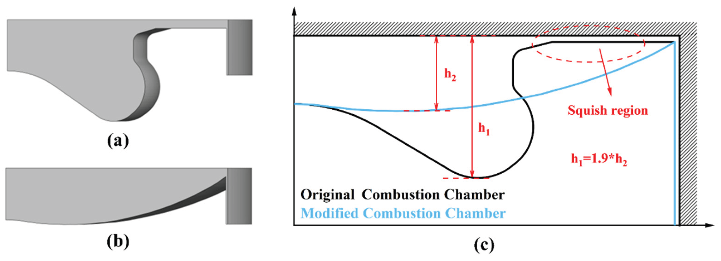
Figure 3.
Effects of AER and CCG on combustion characteristics: (a) in-cylinder pressure and HRR; (b) combustion phasing; (c) mean temperature; (d) ITE and unburned losses.
Figure 3.
Effects of AER and CCG on combustion characteristics: (a) in-cylinder pressure and HRR; (b) combustion phasing; (c) mean temperature; (d) ITE and unburned losses.
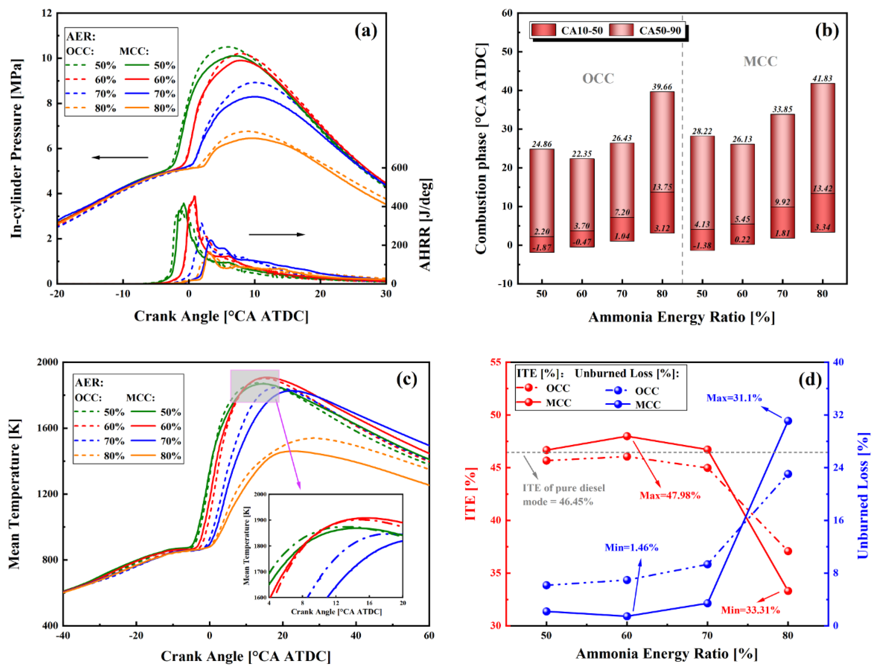
Figure 4.
Effects of AER and CCG on emission characteristics: (a) uDME and uNH3; (b) CO and uHC; (c) CO2, GHG, and N2O; (d) NO, NOX, and NO2.
Figure 4.
Effects of AER and CCG on emission characteristics: (a) uDME and uNH3; (b) CO and uHC; (c) CO2, GHG, and N2O; (d) NO, NOX, and NO2.
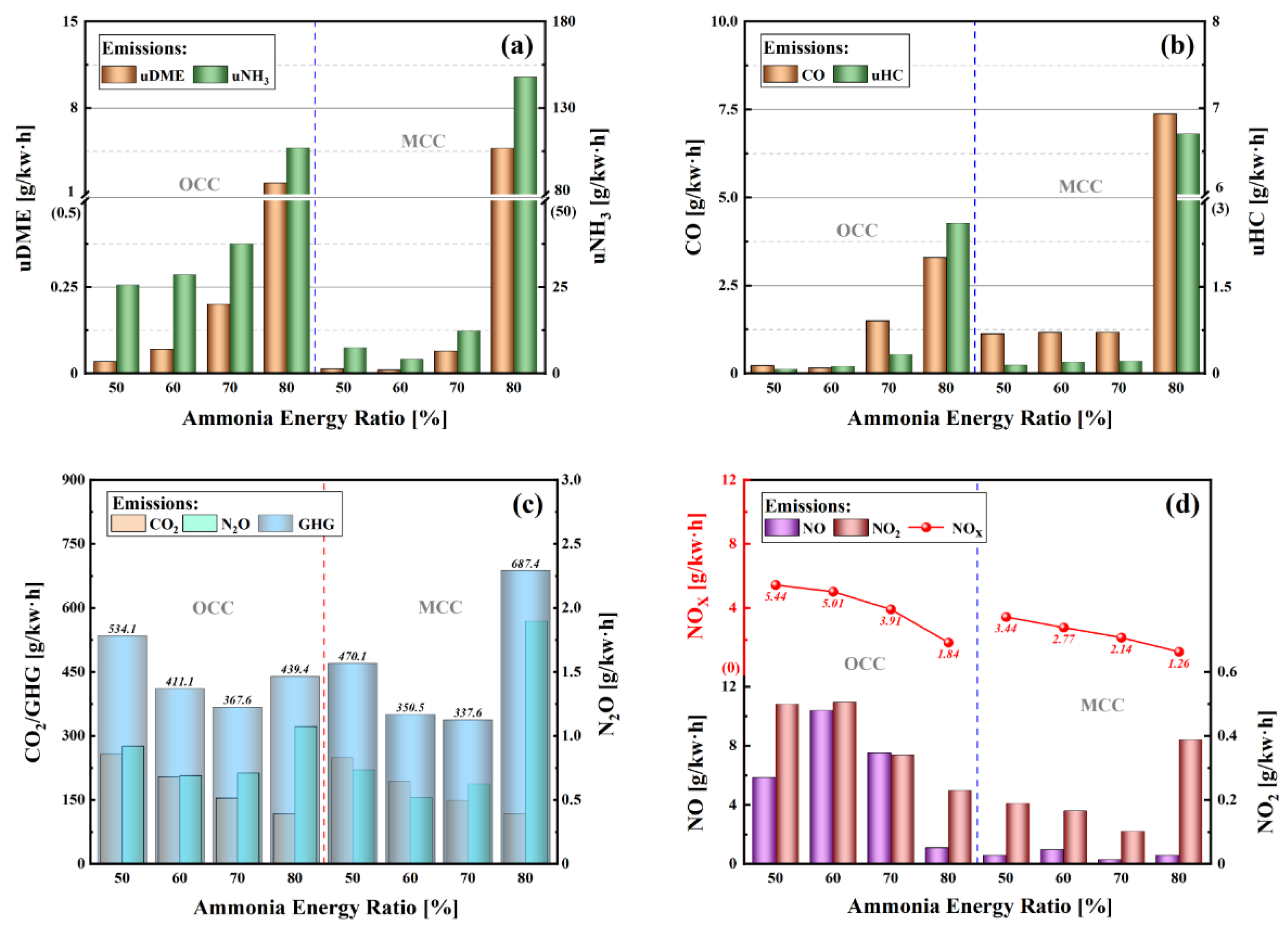
Figure 5.
Effects of SIT and INA on combustion characteristics: (a) in-cylinder pressure and HRR; (b) combustion phasing; (c) mean temperature; (d) ITE and unburned losses.
Figure 5.
Effects of SIT and INA on combustion characteristics: (a) in-cylinder pressure and HRR; (b) combustion phasing; (c) mean temperature; (d) ITE and unburned losses.
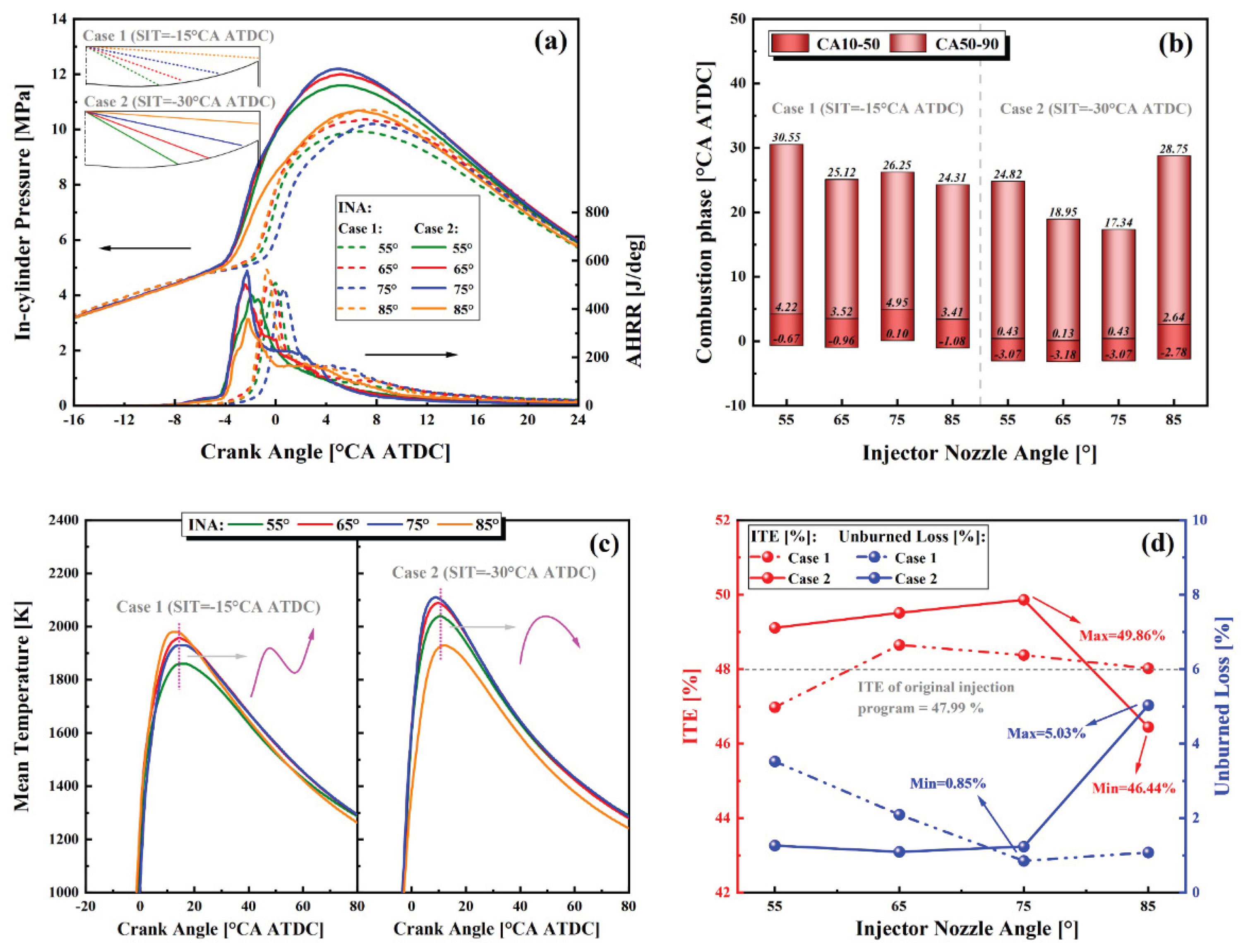
Figure 6.
Effects of different INAs on the spatial-temporal distribution of key parameters and species concentrations during the main combustion phase under different injection timings: (a) Case 1 (SIT = -15 °CA ATDC); (b) Case 2 (SIT = -30 °CA ATDC).
Figure 6.
Effects of different INAs on the spatial-temporal distribution of key parameters and species concentrations during the main combustion phase under different injection timings: (a) Case 1 (SIT = -15 °CA ATDC); (b) Case 2 (SIT = -30 °CA ATDC).
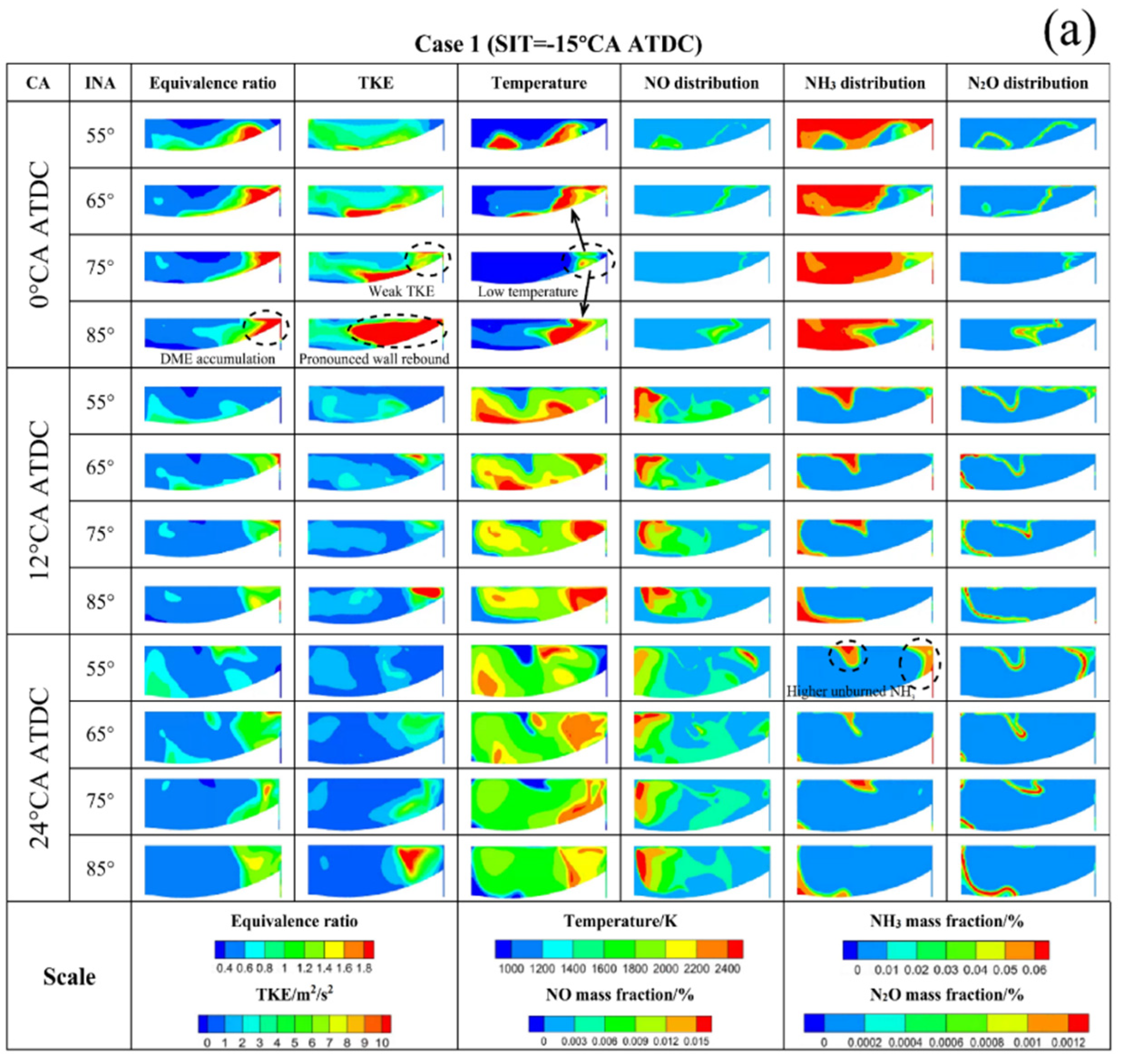
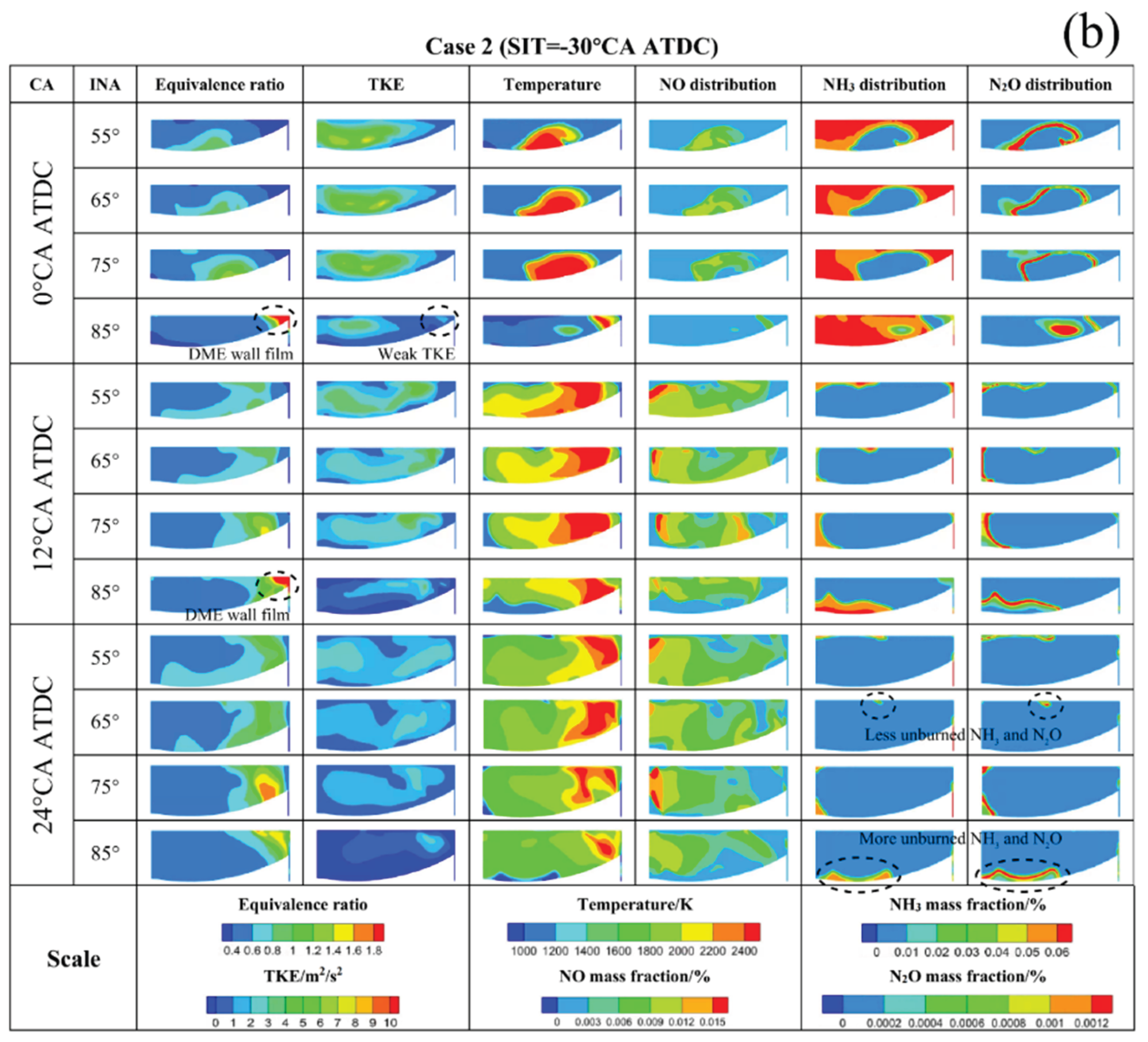
Figure 7.
Effects of SIT and INA on emission characteristics: (a) uDME and uNH3; (b) CO and uHC; (c) CO2, GHG, and N2O; (d) NO, NOX, and NO2.
Figure 7.
Effects of SIT and INA on emission characteristics: (a) uDME and uNH3; (b) CO and uHC; (c) CO2, GHG, and N2O; (d) NO, NOX, and NO2.
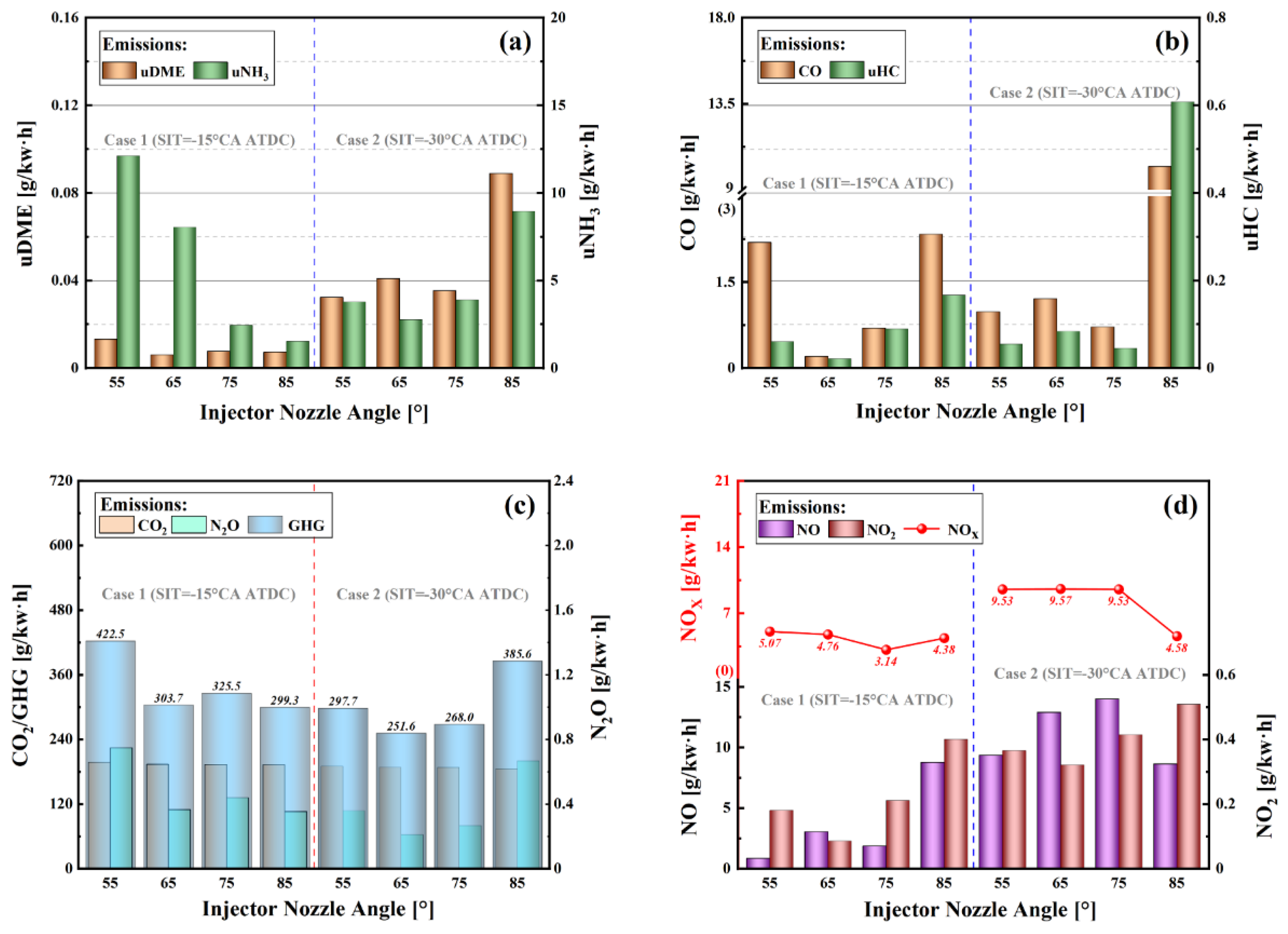
Figure 8.
Effects of different SITs and INAs on the performance of the ADME-DF engine: (a) uNH3 emissions; (b) ITE; (c) GHG emissions; (d) NOX emissions.
Figure 8.
Effects of different SITs and INAs on the performance of the ADME-DF engine: (a) uNH3 emissions; (b) ITE; (c) GHG emissions; (d) NOX emissions.
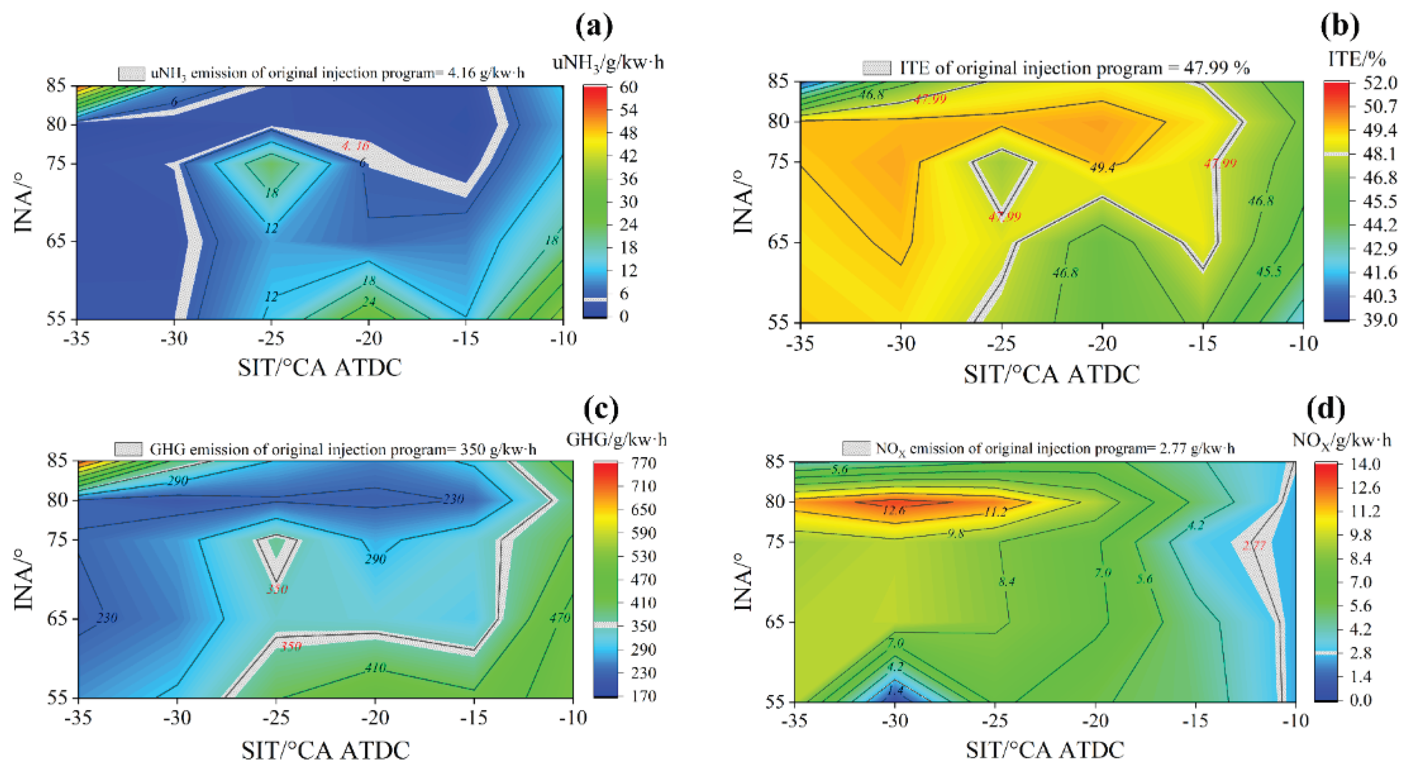
Figure 9.
Effects of different SITs and INAs on the operating stability of the ADME-DF engine: (a) MPRR; (b) RI.
Figure 9.
Effects of different SITs and INAs on the operating stability of the ADME-DF engine: (a) MPRR; (b) RI.
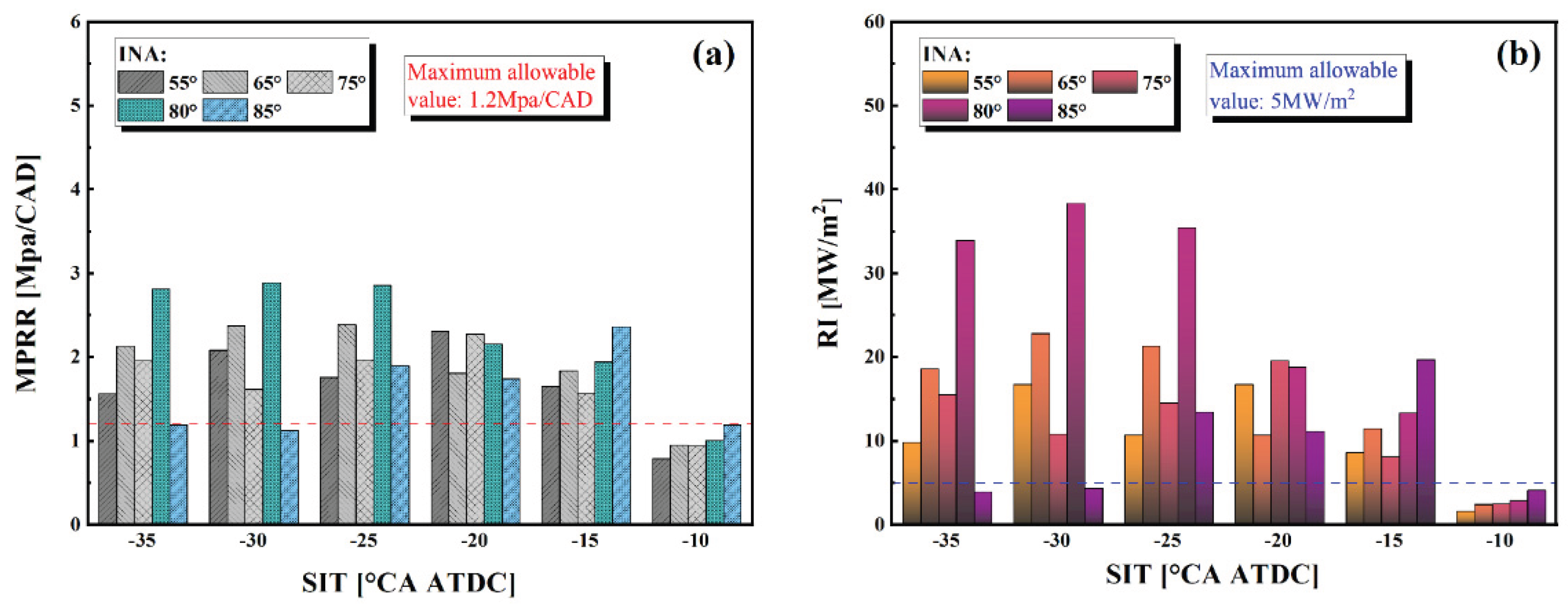
Figure 10.
Effects of PIT and PIR on combustion characteristics: (a) In-cylinder pressure and HRR; (b) Combustion phasing; (c) mean temperature; (d) ITE and unburned loss.
Figure 10.
Effects of PIT and PIR on combustion characteristics: (a) In-cylinder pressure and HRR; (b) Combustion phasing; (c) mean temperature; (d) ITE and unburned loss.
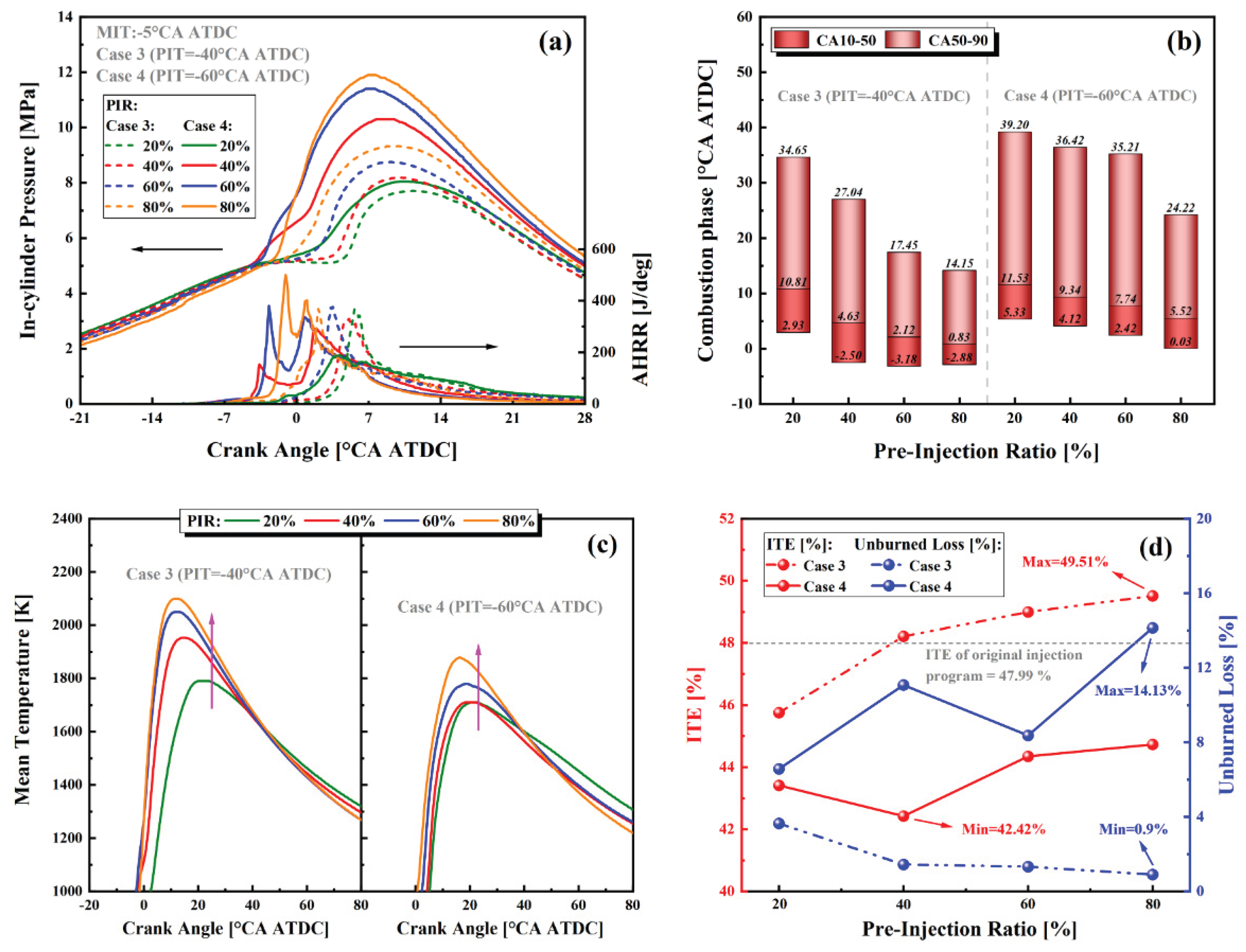
Figure 11.
Effects of PIT and PIR on emission characteristics: (a) uDME and uNH3; (b) CO and uHC; (c) CO2, GHG, and N2O; (d) NO, NOX, and NO2.
Figure 11.
Effects of PIT and PIR on emission characteristics: (a) uDME and uNH3; (b) CO and uHC; (c) CO2, GHG, and N2O; (d) NO, NOX, and NO2.
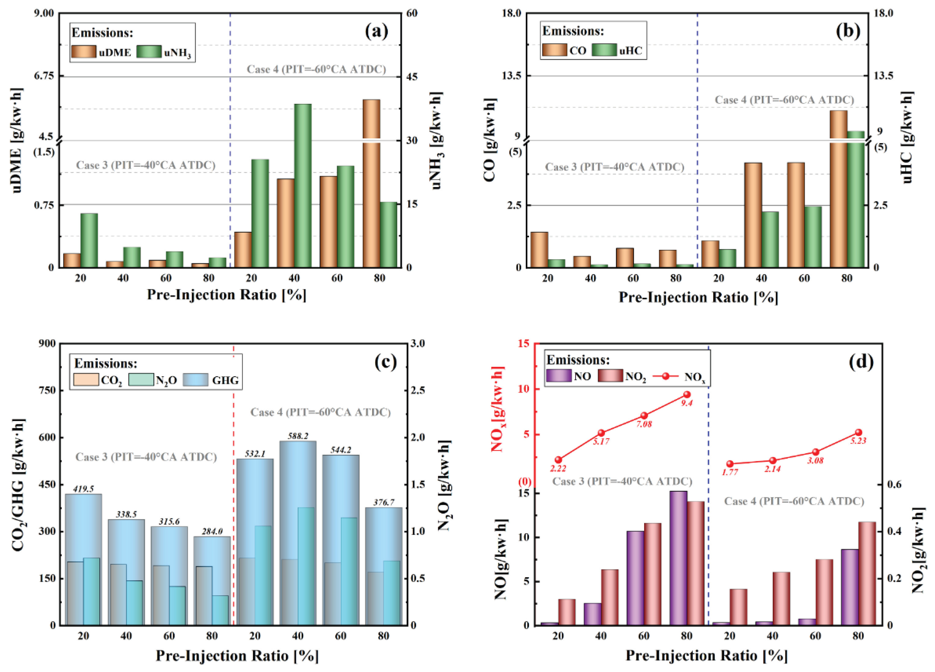
Figure 12.
Effects of different PITs and PIRs on the performance of the ADME-DF engine: (a) uNH3 emissions; (b) ITE; (c) GHG emissions; (d) NOX emissions.
Figure 12.
Effects of different PITs and PIRs on the performance of the ADME-DF engine: (a) uNH3 emissions; (b) ITE; (c) GHG emissions; (d) NOX emissions.
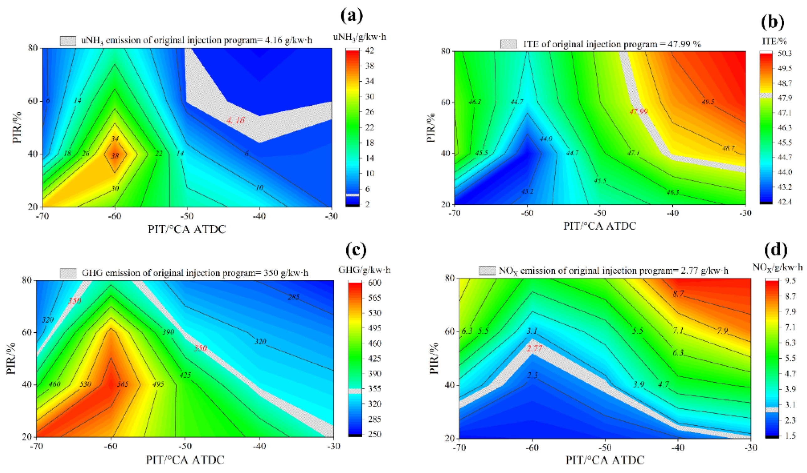
Figure 13.
Effects of different PITs and PIRs on the operating stability of the ADME-DF engine: (a) MPRR; (b) RI.
Figure 13.
Effects of different PITs and PIRs on the operating stability of the ADME-DF engine: (a) MPRR; (b) RI.
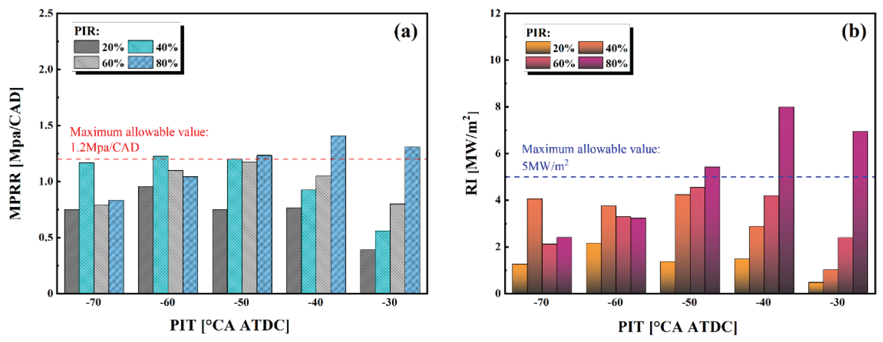
Figure 14.
Comprehensive comparison of combustion and emission characteristics under different injection strategies: (a) Single injection; (b) Split injection.
Figure 14.
Comprehensive comparison of combustion and emission characteristics under different injection strategies: (a) Single injection; (b) Split injection.
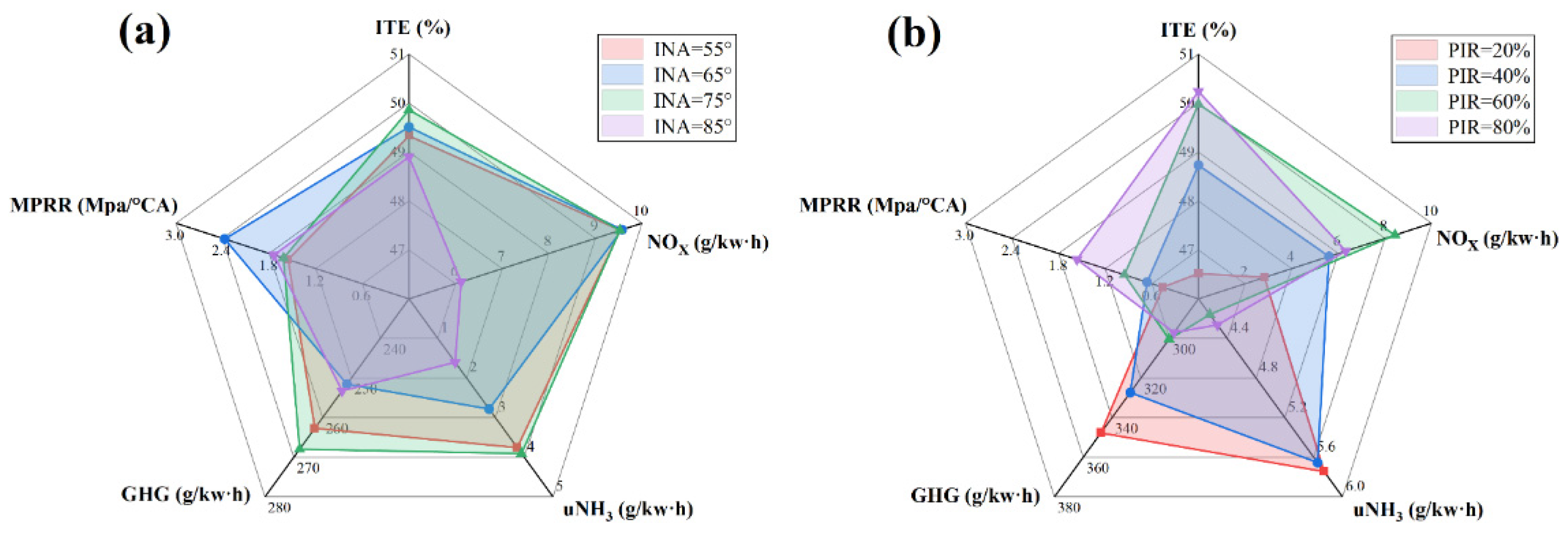

Table 1.
The fuel properties.
| Properties | NH3 | Diesel | H2 | DME |
| Lower heating value (MJ/kg) | 18.8 | 45 | 120 | 28.8 |
| Autoignition temperature (K) | 923 | 530-560 | 775-850 | 508 |
| Flammability limit (vol, %) | 15-28 | 0.6-5.5 | 4-75 | 3.4-17 |
| Adiabatic flame temperature (°C) | 2073 | 2400 | 2383 | 1920 |
| Laminar flame speed at φ = 1(cm/s) | 7 | 86 | 290-350 | 28-35 |
| Stoichiometric air–fuel ratio (/) | 6.03 | 14.5 | 34.3 | 9.0 |
Table 2.
Engine specifications.
| Specification | Unit | Value |
| Engine model | - | DK 32 |
| Number of cylinders | - | 1 |
| Bore×Stroke | mm | 113×140 |
| Total displacement | L | 1.404 |
| Compression ratio | - | 17.5 :1 |
| Rated power | kW | 23.53 |
| Combustion chamber | - | ω |
| Number of spray holes | - | 7 |
| Nozzle hole diameter | mm | 0.19 |
| Intake valve closing (IVC) | °CA ATDC | -169.7 |
| Exhaust valve opening (EVO) | °CA ATDC | 145.3 |
Table 3.
Sub-models used in the simulation.
| Models | Name |
| Turbulence model | RNG k-ε |
| Break-up model | KH-RT |
| Wall heat transfer model | O’Rourke and Amsden |
| Drop evaporation model | The Frossling correlation |
| Collision model | NTC |
| Combustion model | SAGE |
| NOX emission | Extended Zeldovich |
Table 4.
Computational boundary conditions.
| Parameters | Unit | Value |
| Injection pressure (DME) | bar | 300 |
| Speed | rpm | 1200 |
| IVC pressure | bar | 1.2 |
| IVC temperature | K | 340 |
| Piston temperature | K | 500 |
| Wall temperature | K | 460 |
| Head temperature | K | 500 |
| Swirl ratio | - | 1.2 |
Table 5.
Case parameters used in the simulation.
| Test No. | DEM injection strategy | Parameters | Value |
| - | - | NH3 fuel injection | 98 mg/cyc PFI @ 60%AER |
| - | - | DME fuel injection | 42 mg/cyc DI @ 300bar |
| 1 | Single injection | DME injection nozzle angle (INA) |
55°/65°/75°/80°/85° |
| DME single injection timing (SIT) |
-35/-30/-25/-20/-15/-10 °CA ATDC | ||
| 2 | Double injection | DME main injection timing (MIT) | -5 °CA ATDC |
| DME pre-injection timing (PIT) | -30/-40/-50/-60/-70 °CA ATDC | ||
| DME pre-injection ratio (PIR) |
20%/40%/60%/80% |
Disclaimer/Publisher’s Note: The statements, opinions and data contained in all publications are solely those of the individual author(s) and contributor(s) and not of MDPI and/or the editor(s). MDPI and/or the editor(s) disclaim responsibility for any injury to people or property resulting from any ideas, methods, instructions or products referred to in the content. |
© 2026 by the authors. Licensee MDPI, Basel, Switzerland. This article is an open access article distributed under the terms and conditions of the Creative Commons Attribution (CC BY) license (http://creativecommons.org/licenses/by/4.0/).
Copyright: This open access article is published under a Creative Commons CC BY 4.0 license, which permit the free download, distribution, and reuse, provided that the author and preprint are cited in any reuse.


