
Submitted:
11 July 2026
Posted:
13 July 2026
You are already at the latest version
Abstract
The offshore photovoltaic coupled electrolysis hydrogen production system operates in complex marine environments, which puts high requirements on safety for operation and maintenance. To reduce manual intervention and improve operational safety, this paper proposes a surface electromyography (sEMG)-driven cable-actuated continuum manipulator for offshore photovoltaic coupled hydrogen production operation and maintenance(O&M). The sEMG signals from the operator's upper limb are collected, filtered, and mapped onto the desired trajectories. The genetic algorithm-back propagation(BP) neural network pattern classifier is designed for motion classification. Kinematic and dynamic models, as well as the torque controller of the cable-driven continuum manipulator are established. Experimental results demonstrate that the proposed method can identify upper-limb motion intention and drive the cable-actuated continuum manipulator to follow the desired trajectories with high accuracy. This lays a foundation for operation and maintenance tasks in offshore photovoltaic coupled electrolysis hydrogen production systems.
Keywords:
cable-driven continuum manipulator
; genetic algorithm
; back propagation neural network
; offshore photovoltaic coupled hydrogen production
1. Introduction
Offshore photovoltaic coupled electrolysis hydrogen production systems represent an important direction for marine energy utilization [1,2]. Compared with traditional offshore photovoltaic systems, such systems include floating photovoltaic modules, floating bodies, brackets, cable connections, power conversion units, hydrogen production equipment, auxiliary hydrogen storage units and multiple energy transmission interfaces. Their equipment composition is more complex, the energy conversion chain is longer, and the O&M objects are more diverse, which places higher requirements on safe, stable and flexible maintenance.
Existing studies on offshore floating photovoltaic and photovoltaic-hydrogen systems have mainly focused on system design, energy management, and hydrogen production performance [3]. Research on electrolysis hydrogen production has further promoted the feasibility of hydrogen production under marine conditions, including direct electrolysis using floating platforms [4,5]. For floating photovoltaic systems, cleaning strategies and reliability improvement have also been investigated to support long-term stable operation [6]. In addition, remote inspection and maintenance technologies have been explored for offshore and underwater industrial infrastructure [7,8]. Photovoltaic panel cleaning robots and robotic-arm-based dust mitigation systems have also been developed for solar panel maintenance [9,10]. These studies provide important support for system design, monitoring, and maintenance. However, they do not sufficiently address close-range physical O&M tasks, such as photovoltaic panel surface cleaning, near-field inspection of floating bodies, brackets, and cables, checking hydrogen-production interfaces, and contact maintenance around narrow or shielded equipment. These tasks require the end-effector to approach fragile panels, flexible cables and irregular connectors, so collision risk, scraping risk and contact safety become central problems rather than secondary details.
Traditional rigid manipulators have high positioning accuracy and load capacity, but they are not naturally suited to the above contact-sensitive offshore tasks. Offshore photovoltaic coupled hydrogen production platforms are affected by wind-wave disturbances, platform motion, salt-spray corrosion, equipment occlusion and confined layouts. The O&M objects may have uncertain positions, nonstandard shapes and limited operating spaces. A rigid manipulator with large structural stiffness and distal inertia may amplify accidental contact forces under platform motion, thereby increasing the risk of scratching photovoltaic modules, colliding with brackets, pulling flexible cables or damaging hydrogen-production auxiliary components. Therefore, directly applying a traditional rigid manipulator to such systems is likely to weaken operational safety and environmental adaptability.
Flexible manipulators and cable-driven continuum manipulators provide a more suitable structural route for these O&M requirements. A flexible or continuum manipulator can generate motion through continuous body bending rather than only through discrete rigid joints [11,12,13,14]. For the cable-driven continuum manipulator, the actuators can be arranged at the base or away from the distal end, while the bending state of the manipulator is controlled by adjusting cable lengths or cable tensions. This arrangement reduces distal mass, improves compactness and makes the cable-driven continuum manipulator more suitable for near-field inspection, panel-adaptive cleaning and safe operation around floating bodies, brackets, cables and hydrogen-production equipment.
However, the offshore photovoltaic coupled hydrogen production platforms are subject to dynamic disturbances, strong reflection from water and photovoltaic panels, changing illumination, visual occlusion, local contamination, cable interweaving and task uncertainty. These factors may reduce the stability of perception, make path planning unreliable, and increase the difficulty of force-safe contact control. Communication delay or interruption may further reduce the reliability of remote autonomous execution. Therefore, many offshore maintenance tasks still require the operator's experience, judgment and real-time decision-making, especially when the task target is uncertain or the allowable contact force is difficult to model.
SEMG provides a natural human-machine interaction signal for introducing human intention into the control loop. As a non-invasive bioelectrical signal, sEMG can reflect muscle activation and upper-limb motion intention, and has been widely used in robot control, natural human-machine interfaces, rehabilitation robots, prosthetic control and teleoperation control [15,16,17]. By decoding the operator’s sEMG signals, the upper-limb motion intention can be mapped to the motion command of the cable-actuated continuum manipulator. In this way, the operator remains responsible for task-level judgment and decision-making, while the flexible manipulator performs compliant and safe contact operations at the offshore site. However, accurate motion intention recognition from sEMG signals remains challenging because the signals are weak, nonlinear, and easily affected by noise, electrode placement, muscle fatigue, and inter-subject differences. To improve recognition performance, optimization-based neural network methods have been introduced into sEMG pattern recognition. For example, genetic algorithm-back propagation methods have been used for gait recognition and lower-limb motion pattern recognition based on sEMG signals [18,19]. In addition to discrete pattern classification, previous studies have also explored sEMG-based continuous motion prediction, gait recognition, and human–robot cooperative control [20,21,22]. For manipulator-related applications, surface electromyography-based action recognition and manipulator control provide a direct reference for using muscle signals as control inputs [23], while online adaptive prediction of human motion intention further improves the adaptability of sEMG-based recognition models [24]. In upper-limb applications, sEMG-based motion recognition and human arm motion mapping have been investigated for rehabilitation and human–machine interaction [25,26]. Recent studies have also introduced deep learning and optimized learning frameworks to improve the accuracy and robustness of sEMG-based gesture and motion recognition [27,28,29,30].
Among these methods, the BP neural network is more suitable for nonlinear mapping, but its performance is sensitive to the initial weights and thresholds. The genetic algorithm (GA) can provide a global search strategy for optimizing these initial parameters and reducing the possibility of local optima. Therefore, the genetic algorithm-optimized back propagation (GA-BP) neural network is adopted in this study to construct an sEMG-based motion intention classifier for controlling the cable-actuated continuum manipulator.
To address the above issues, this paper proposes an sEMG-driven cable-actuated continuum manipulator for the safe O&M of offshore photovoltaic coupled electrolysis hydrogen production systems. The main contributions of this work are summarized as follows:
(1) An sEMG-driven control framework is proposed for offshore photovoltaic coupled electrolysis hydrogen production O&M tasks, enabling the operator’s upper-limb motion intention to be introduced into the control process of the cable-actuated continuum manipulator.
(2) A GA-BP neural network pattern classifier is constructed for sEMG-based motion intention recognition, providing reliable motion classification results for generating control commands.
(3) Kinematic and dynamic models, as well as the torque control method, are established for the cable-driven continuum manipulator. The trajectory tracking performance of the proposed method is validated through both simulation and experiments.
The rest of this paper is organized as follows: Section 2 presents the overall scheme of the proposed sEMG-driven cable-actuated continuum manipulator. Section 3 describes the sEMG signal acquisition and preprocessing, the GA-BP neural network pattern classifier, and the mathematical model of the cable-driven continuum manipulator. Section 4 presents the simulation and experimental validation results. Section 5 summarizes the works of this paper.
2. System Overview
Figure 1 illustrates the overall scheme of the proposed sEMG-driven cable-actuated continuum manipulator for offshore photovoltaic coupled hydrogen production operation and maintenance. The proposed sEMG-driven cable-actuated continuum manipulator consists of a master-side and a slave-side motion system. On the master side, the operator’s upper limb is equipped with a sEMG signal acquisition unit. The collected signals are preprocessed on the host computer, including filtering and feature extraction, to improve signal stability and usability. Subsequently, feature mapping and decoding are performed on the processed sEMG signals to extract the corresponding joint-motion intention parameters, which are then transmitted to the torque controller to generate actuation control commands. On the slave side, the control unit takes the desired trajectories of the end-effector as the input for each joint. By establishing the kinematic and dynamic models of the manipulator and solving the inverse dynamics, the manipulator control unit drives the cable-driven continuum manipulator to achieve synchronized trajectory tracking.
3. Methods
3.1. sEMG Signals Acquisition and Preprocessing
3.1.1. sEMG Signals Acquisition
The sEMG signal acquisition is used to measure and record the bioelectrical activity generated by skeletal muscles during contraction, making it an important approach for human motion intention recognition. The selection of muscle sites for sEMG signal acquisition usually depends on the specific research objectives and application scenarios. Studies have shown that the muscles of the upper limb can generally be divided into the upper-arm muscle group and the forearm muscle group. Considering the arm motions investigated in this study, the biceps brachii was selected as the primary sEMG acquisition site.
The basic information of the subjects is presented in Table 1, and each subject completed the sEMG signal acquisition motions shown in Figure 2. Motion 1 was defined as raising the upper limb upward by 45°, Motion 2 as lowering the upper limb downward by 45°, Motion 3 as rotating the upper limb to the left by 45°, and Motion 4 as rotating the upper limb to the right by 45°. Each motion was performed continuously 10 times as one set, with three sets completed in total. A rest interval of 30 s was provided between consecutive sets to minimize fatigue effects.
Figure 3.
Raw biceps brachii signals for each motion.
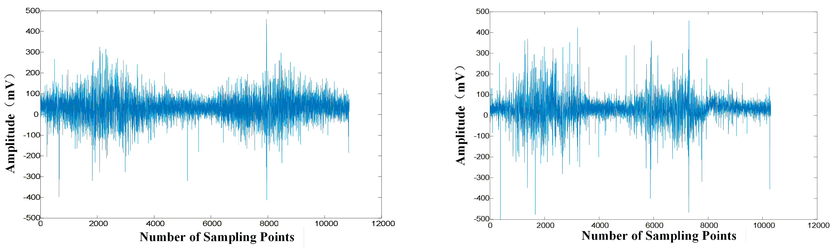
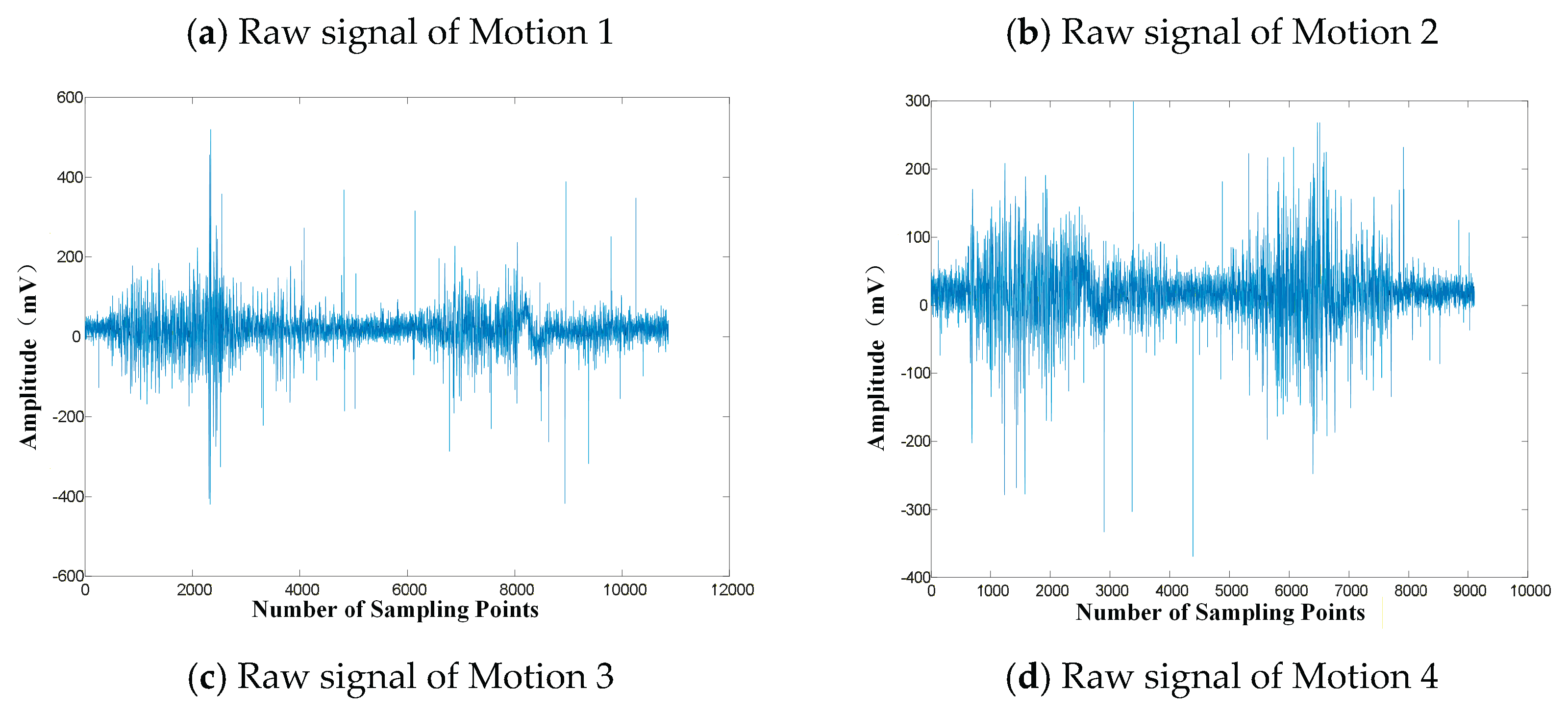
3.1.2. sEMG Signals Filtering
Figure 4 shows the waveform comparison results of four movements before and after filtering. As can be seen from Figure 4, compared with the raw signals, the sEMG signals filtered by Butterworth band-pass filtering exhibit significantly reduced high-frequency random noise and low-frequency baseline drift, resulting in more stable and continuous waveforms. Meanwhile, while preserving the main muscle activation peaks and the overall envelope trends, the filtered signals effectively suppress non-physiological noise components. This indicates that the Butterworth band-pass filtering method can enhance useful information and suppress noise without altering the primary time-domain structural characteristics of the sEMG signals.
Figure 5, Figure 6, Figure 7 and Figure 8 show the frequency-domain distributions of the biceps brachii sEMG signals before and after filtering during different motions. It can be observed that, after Butterworth band-pass filtering, the low-frequency noise components below 20 Hz and high-frequency interference in the signals are both significantly suppressed. These results indicate that the adopted filtering method can effectively improve the signal-to-noise ratio, thereby laying a solid foundation for subsequent sEMG feature extraction and motion classification.
3.1.3. sEMG Signals Feature Extraction
Since raw sEMG signals are nonlinear, and highly susceptible to noise, they cannot be directly used for motion intention recognition. Therefore, feature extraction is necessary to transform the filtered sEMG signals into compact and representative feature vectors. These features can effectively describe muscle activation intensity, temporal variation, and frequency distribution during upper-limb movements, thereby reducing data dimensionality and enhancing the separability among different motion patterns. Consequently, sEMG feature extraction provides reliable input information for the subsequent GA-BP neural network classifier and improves the accuracy and robustness of motion intention recognition. The time-domain feature extraction results of the biceps brachii are shown in Figure 9.
3.2. Design of the GA-BP Neural Network Pattern Classifier
To realize sEMG-based motion intention recognition, a GA-BP neural network were established as pattern classifiers in this study. The extracted time-domain features of the sEMG signals were used as the input of the classifier, and the corresponding upper-limb motion categories were used as the output. The four predefined motions were labeled as Motion 1, Motion 2, Motion 3, and Motion 4, respectively.
Although the BP neural network has good nonlinear mapping capability, its classification performance is influenced by the initial weights and thresholds. In addition, the standard BP neural network may converge slowly and become trapped in local optima during training. To overcome these limitations, the GA was introduced to optimize the initial weights and thresholds of the BP neural network.
The flowchart of the GA-BP pattern classifier is shown in Figure 10. The weights and thresholds of the BP neural network were first encoded as chromosomes. Each chromosome represented a candidate set of initial network parameters. The initial population was then generated, and the fitness value of each individual was evaluated according to the classification error of the BP neural network. Individuals with higher fitness were selected for the next generation, while crossover and mutation operations were performed to generate new candidate solutions and maintain population diversity. After iterative evolution, the optimal individual obtained by the genetic algorithm was decoded and used as the initial weights and thresholds of the BP neural network. The BP neural network was then further trained through error back propagation to complete the classification of different sEMG motion signals. Therefore, the proposed GA-BP pattern classifier combines the global search capability of the genetic algorithm with the local learning capability of the BP neural network.
The classification results of the BP neural network for the four different motion signals are shown in Figure 11. Among 1200 samples, 840 samples are used as the training set and 360 samples were used as the test set. The training accuracy reached 93.75%, while the test accuracy is approximately 91.87%. The classification results of the genetic algorithm-optimized BP neural network are shown in Figure 12. The training accuracy increased to approximately 96.88%, and the test accuracy increased to approximately 94.72%. This indicate that the GA-BP pattern classifier can improve the recognition accuracy of sEMG-based motion intention classification and provide more reliable control commands for the cable-actuated continuum manipulator.
3.3. Mathematical Model of the Cable-Driven Continuum Manipulator
3.3.1. Kinematic Modeling
1. Kinematic model between joint space and actuation space
The kinematic model between actuation space and joint space aims to establish the mapping relationship between the bending deflection angles and the length variations of the actuation cables . Under the ideal bending assumption, the cable-driven continuum manipulator can be approximated as a constant-curvature model. The arc length is equal to the product of the bending radius and the corresponding central angle. Figure 13 shows the structural schematic of the bending deformation of a single-section manipulator. In the figure, denotes the central angle corresponding to the arc length, denotes the equivalent bending angle of the single-section manipulator in the plane, represents the initial axial position point, represents the position reached after bending deformation, and denotes the bending radius of the axial line of the single-section manipulator.
According to Figure 13(a), the lengths of the actuation cables can be expressed as follows:
When the manipulator does not bend, the actuation cables and the central backbone have the same length l. When the manipulator undergoes bending deflection characterized by , the length variations of the actuation cables can be expressed as follows:
where and denote the length variations of the and actuation cables of the single-section manipulator, respectively.
2. Kinematic model between joint space and task space
The mapping relationship between joint space and task space of the continuum manipulator is established by determining the relationship between the bending angle and rotation angle of each section and the end-effector position (x, y, z).
As shown in Figure 14, the same modeling method as that used for the single-section manipulator is adopted, and coordinate frames , …, are established at the center points of the proximal and distal end disks of each section (O, A, B, C, D, E). The homogeneous transformation matrix i−1 represents the pose transformation from the end coordinate frame of the i-th section to that of the previous section.
The D-H parameters of the proposed cable-driven continuum manipulator are shown in Table 2.
The kinematic mapping relationship from joint space to task space of the entire cable-driven continuum manipulator can be represented by the homogeneous transformation matrix 0 from the base coordinate frame to the end coordinate frame . According to the chain rule, 0 can be expressed as follows:
3.3.2. Torque Controller
The dynamic model of the cable-driven continuum manipulator can be expressed as follows:
where is the joint position vector, is the joint angular velocity vector, is the joint angular acceleration vector, is the inertia matrix, is the Coriolis and centrifugal matrix, is the gravity term, and is the joint torque vector. The position error and velocity error of the cable-driven continuum manipulator can be expressed as follows:
where is the desired joint position vector and is the desired joint velocity vector. The control torque of the cable-driven continuum manipulator can be expressed as follows:
where and are the proportional and derivative gain matrices, respectively.
4. Results and Discussion
4.1. Simulation Validation
4.1.1. Kinematic Simulation
The motion trajectory of the cable-driven continuum manipulator was planned based on the Cartesian coordinate system. The initial joint angles of the cable-driven continuum manipulator were set to (-90°, 0°, 0°, 0°, 0°, 0°, 0°), and the final joint angles were set to (11°, 22°, -19°, -29°, 33°, 36°, 27°). The simulation time was set to 8s, and the kinematic simulation results of the cable-driven continuum manipulator are shown in Figure 15. It can be seen from Figure 15 that the end-effector trajectory of the cable-driven continuum manipulator is in good agreement with the theoretical results. In addition, the joint angle and joint velocity curves of the cable-driven continuum manipulator vary continuously. This indicates that the cable-driven continuum manipulator can perform trajectory tracking tasks continuously and stably.
4.1.2. Torque Control Simulation
The system simulation model of the torque controller for the cable-driven continuum manipulator is shown in Figure 16, and both and are set to 10.
The torque control simulation trajectories of the cable-driven continuum manipulator are shown in Figure 17, including the desired trajectory tracking of each joint angle and the variation curves of joint torque errors. As shown in Figure 17(a)–(e), the actual motion curves of each joint basically coincide with the desired trajectories. This indicates that the designed torque controller has a fast response speed and good transient regulation capability. From the overall trend, no obvious oscillation or amplified overshoot occurs in any joint throughout the entire motion cycle. This demonstrates that the designed torque controller can effectively suppress the effects of flexible coupling and nonlinear disturbances in the cable-driven system. As shown in Figure 17(f), although the errors differ among the joints, the trajectory tracking errors of all joints remain within 0.2° and are generally maintained at a low level. This indicates that the designed torque controller can achieve effective tracking of the desired trajectories. Therefore, the torque controller designed for the proposed cable-driven continuum manipulator can not only achieve high-precision joint trajectory tracking but also effectively suppress dynamic errors and coupling disturbances introduced by the flexible actuation system.
4.2. Experiment Validation
4.2.1. Experimental Setup
For the sEMG-based motion intention recognition control study proposed in this paper, an experimental platform for the cable-driven continuum manipulator was established, as shown in Figure 18. The platform mainly consists of an sEMG signal acquisition unit, a control unit, an actuation unit, a host-computer processing unit, and a cable-driven continuum manipulator unit.
4.2.2. Validation of the sEMG-Driven Cable-Actuated Continuum Manipulator
(1) Single-Point Trajectory Tracking Accuracy
Five subjects were selected for this experiment, including two males and three females, with ages ranging from 23 to 28 years. The sEMG signals from the subjects’ arms were collected as control signals, while the motion trajectory of the cable-driven continuum manipulator was recorded simultaneously. The experimental environment is shown in Figure 19(a). The subjects repeatedly performed the four predefined arm motions, with each motion repeated for 20 sets. A total of 400 experimental trials were completed by the five subjects. The experimental results are presented in Table 3, and partial real-time sEMG signal acquisition results are shown in Figure 19(b).
During the experiment, the operator completed the four motions shown in Figure 3. The motion recognition results obtained through pattern classification were used as the desired trajectories of the cable-actuated teleoperated manipulator. As shown in Table 3, the cable-actuated continuum manipulator executed the operator’s motions with an accuracy of more than 90%. This verifies that the proposed sEMG-driven cable-actuated continuum manipulator can achieve high-precision single-point trajectory tracking.
(2) Continuous Trajectory Tracking Accuracy
The experimental results of continuous trajectory tracking accuracy are shown in Figure 20. As observed from the comparison, although certain deviations exist between the simulated and experimental tracking trajectories, the overall motion trends remain consistent. This indicates that the designed cable-driven continuum manipulator can effectively follow the desired trajectory, thereby verifying the rationality and feasibility of the proposed torque controller. The trajectory tracking errors can mainly be attributed to the differences between the ideal simulation environment and the actual experimental conditions. In the simulation, the system is assumed to operate under ideal conditions, whereas in the physical experiment, factors such as motor response delay, variations in upper-limb motion, actuator backlash, cable compliance, and sensor measurement errors may introduce trajectory deviations. In addition, environmental factors, including temperature variation, humidity, and external electromagnetic interference, may affect the performance of motors, sensors, and control signal transmission, thereby reducing motion accuracy.
(3) Effectiveness of Torque Controller
To verify the effectiveness of the designed torque control method, a motion angle tracking experiment was conducted on the cable-driven continuum manipulator. In the experiment, angle sensors were installed at the end-effector of the cable-driven continuum manipulator and on the subject’s forearm to acquire and record the joint rotation angles in real time. The comparative experimental results between the end-effector posture of the cable-driven continuum manipulator and the joint motion angles of the human upper limb are shown in Figure 21. The experimental results show that, under the four different motions, the end-effector of the cable-driven continuum manipulator can effectively track the motion variation trends of the corresponding joints of the human upper limb. This verifies the effectiveness and stability of the proposed torque controller.
Therefore, the proposed sEMG-driven cable-actuated continuum manipulator can accurately recognize human motion intention and effectively track the target trajectory. The experimental results demonstrate that the proposed sEMG-driven cable-actuated continuum manipulator has good adaptability and application potential in complex unstructured environments during the operation and maintenance of offshore photovoltaic coupled electrolysis hydrogen production systems.
5. Conclusions
To reduce the risks of photovoltaic module scratching, support structure collision, flexible cable pulling, and damage to auxiliary hydrogen production components caused by conventional rigid manipulators during operation and maintenance of offshore photovoltaic-coupled hydrogen production platforms, this paper proposes an sEMG-driven cable-actuated continuum manipulator for offshore photovoltaic coupled electrolysis hydrogen production operation and maintenance. It acquires upper-limb sEMG signals from the operator, while the cable-actuated continuum manipulator can achieve synchronized trajectory tracking. The proposed method provides a feasible technical approach for safe, flexible, and remote operation and maintenance of offshore photovoltaic coupled hydrogen production equipment in complex marine environments. Although the proposed sEMG-driven cable-actuated continuum manipulator demonstrated promising motion intention recognition and trajectory tracking performance, the experiments were mainly conducted in the laboratory environment, and the effects of real offshore disturbances, including waves, wind loads, platform motion, salt spray, and illumination changes, were not fully considered. Future work will consider marine environmental factors, including waves and wind speed, to further optimize the control algorithm for the sEMG-driven cable-actuated continuum manipulator.
Author Contributions
Conceptualization, L.M., F.H. and Q.F.; methodology, L.M.; software, L.M., Z.D. and Y.M.; validation, L.M., Z.D. and Y.M.; formal analysis, L.M. and Z.D.; investigation, L.M., Y.M. and Z.Y.; resources, Z.Y., F.H. and Q.F.; data curation, L.M., Z.D. and Z.Y.; writing—original draft preparation, L.M.; writing—review and editing, Z.D., Y.M., Z.Y., F.H. and Q.F.; visualization, L.M., Z.D. and Z.Y.; supervision, F.H. and Q.F.; project administration, F.H. and Q.F.; funding acquisition, F.H. and Q.F. All authors have read and agreed to the published version of the manuscript.
Funding
This research is partly supported by the National Key R&D Program of China (grant number 2023YFB4005105), Inner Mongolia Natural Science Foundation (2026QC0391).
Acknowledgments
Authors declared none.
Conflicts of Interest
The authors declare no conflicts of interest.
References
- Lian, J.; Cui, L.; Fu, Q. Offshore renewable energy advance. Mar. Energy Res. 2024, 1, 10006. [Google Scholar] [CrossRef]
- Wu, S.; Jiang, N.; Zhang, S.; Zhang, P.; Zhao, P.; Liu, Y.; Wang, Y. Discussion on the development of offshore floating photovoltaic plants, emphasizing marine environmental protection. Front. Mar. Sci. 2024, 11, 1336783. [Google Scholar] [CrossRef]
- Temiz, M.; Javani, N. Design and analysis of a combined floating photovoltaic system for electricity and hydrogen production. Int. J. Hydrogen Energy 2020, 45, 3457–3469. [Google Scholar] [CrossRef]
- Mishra, A.; Park, H.; El-Mellouhi, F.; Han, D.S. Seawater electrolysis for hydrogen production: Technological advancements and future perspectives. Fuel 2024, 361, 130636. [Google Scholar] [CrossRef]
- Liu, T.; Zhao, Z.; Tang, W.; Chen, Y.; Lan, C.; Zhu, L.; Jiang, W.; Wu, Y.; Wang, Y.; Yang, Z.; et al. In-situ direct seawater electrolysis using floating platform in ocean with uncontrollable wave motion. Nat. Commun. 2024, 15, 5305. [Google Scholar] [CrossRef] [PubMed]
- Zahedi, R.; Ranjbaran, P.; Gharehpetian, G.B.; Mohammadi, F.; Ahmadiahangar, R. Cleaning of floating photovoltaic systems: A critical review on approaches from technical and economic perspectives. Energies 2021, 14, 2018. [Google Scholar] [CrossRef]
- D.N.V. Remote Technology for Offshore Wind Inspection and Maintenance. U.S. Bureau of safety and environmental enforcement, 2023.
- Nauert, F.; Kampmann, P. Inspection and maintenance of industrial infrastructure with autonomous underwater robots. Front. Robot. AI 2023, 10, 1240276. [Google Scholar] [CrossRef] [PubMed]
- Luo, J.; Wang, G.; Lei, Y.; Wang, D.; Chen, Y.; Zhang, H. A photovoltaic panel cleaning robot with a lightweight YOLO v8. Front. Robot. AI 2025, 12, 1606774. [Google Scholar] [CrossRef] [PubMed]
- Ghodki, M.K. An infrared based dust mitigation system operated by the robotic arm for performance improvement of the solar panel. Sol. Energy 2022, 244, 343–361. [Google Scholar] [CrossRef]
- Sitler, J.L.; Wang, L. A modular open-source continuum manipulator for underwater remotely operated vehicles. J. Mech. Robot. 2022, 14, 060906. [Google Scholar] [CrossRef]
- Du, T.; Hughes, J.; Wah, S.; Matusik, W.; Rus, D. Underwater soft robot modeling and control with differentiable simulation. IEEE Robot. Autom. Lett. 2021, 6, 4994–5001. [Google Scholar] [CrossRef]
- Bai, H.; Lee, B.G.; Yang, G.; Shen, W.; Qian, S.; Zhang, H.; Zhou, J.; Fang, Z.; Zheng, T.; Yang, S.; Huang, L.; Yu, B. Unlocking the potential of cable-driven continuum robots: A comprehensive review and future directions. Actuators 2024, 13, 52. [Google Scholar] [CrossRef]
- Gong, Z.; Fang, X.; Chen, X.; Cheng, J.; Xie, Z.; Liu, J.; Chen, B.; Yang, H.; Kong, S.; Hao, Y.; Wang, T.; Wen, L. A soft manipulator for efficient delicate grasping in shallow water: Modeling, control, and real-world experiments. Int. J. Robot. Res. 2021, 40, 449–469. [Google Scholar]
- Song, T.; Yan, Z.; Guo, S.; Li, Y.; Li, X.; Xi, F. Review of sEMG for robot control: Techniques and applications. Appl. Sci. 2023, 13, 9546. [Google Scholar] [CrossRef]
- Zheng, M.; Crouch, M.S.; Eggleston, M.S. Surface electromyography as a natural human-machine interface: A Review. IEEE Sens. J. 2022, 22, 9198–9214. [Google Scholar] [CrossRef]
- Yang, X.; Chen, F.; Wang, F.; Zheng, L.; Wang, S.; Qi, W.; Su, H. Sensor fusion-based teleoperation control of anthropomorphic robotic arm. Biomimetics 2023, 8, 169. [Google Scholar] [CrossRef] [PubMed]
- Ma, Y.; Ma, Y.; Yang, C.; Wang, R.; Xu, X. Application of GA-BP neural network in gait recognition of lower limb movement. Chin. J. Sens. Actuators 2013, 26, 1266–1271. [Google Scholar]
- Cui, B.; Zhang, X.; Deng, J. Research on lower limb motion pattern recognition of surface electromyography signal based on GA-BP. Transducer Microsyst. Technol. 2024, 43, 63–67. [Google Scholar]
- Shi, Y.; Wang, S.; Li, J.; Gao, X.; Lv, J.; Lv, P.; Liu, H.; Zhang, P.; Luo, D.; Che, H.; Zhao, P. Prediction of continuous motion for lower limb joints based on SEMG signal. In Proceedings of the 2020 IEEE International Conference on Mechatronics and Automation, Beijing, China, 13-16 October 2020. [Google Scholar]
- Chang, L.; Yu, H.; Wang, Y.; Zhao, Y. Research on gait recognition of surface EMG signal based on MPSO-LSTM algorithm. J. Mech. Med. Biol. 2023, 23, 2340066. [Google Scholar] [CrossRef]
- Wang, J.; Liu, J.; Zhang, G.; Guo, S. Periodic event-triggered sliding mode control for lower limb exoskeleton based on human-robot cooperation. ISA Trans. 2022, 123, 87–97. [Google Scholar] [CrossRef] [PubMed]
- Cao, T.; Liu, D.; Wang, Q.; Bai, O.; Sun, J. Surface electromyography-based action recognition and manipulator control. Appl. Sci. 2020, 10, 5823. [Google Scholar] [CrossRef]
- Ding, Z.; Yang, C.; Wang, Z.; Yin, X.; Jiang, F. Online adaptive prediction of human motion intention based on sEMG. Sensors 2021, 21, 2882. [Google Scholar] [CrossRef] [PubMed]
- Bu, D.; Guo, S.; Li, H. sEMG-based motion recognition of upper limb rehabilitation using the improved Yolo-v4 algorithm. Life 2022, 12, 64. [Google Scholar] [CrossRef] [PubMed]
- Zheng, Y.; Zheng, G.; Zhang, H.; Zhao, B.; Sun, P. Mapping method of human arm motion based on surface electromyography signals. Sensors 2024, 24, 2827. [Google Scholar] [CrossRef] [PubMed]
- Wang, S.; Huang, L.; Jiang, D.; Sun, Y.; Jiang, G.; Li, J.; Zou, C.; Fan, H.; Xie, Y.; Xiong, H.; et al. Improved multi-stream convolutional block attention module for sEMG-based gesture recognition. Front. Bioeng. Biotechnol. 2022, 10, 909023. [Google Scholar] [CrossRef] [PubMed]
- Zhou, Z.; Tao, Q.; Su, N.; Liu, J.; Chen, Q.; Li, B. Lower limb motion recognition based on sEMG and CNN-TL fusion model. Sensors 2024, 24, 7087. [Google Scholar] [CrossRef] [PubMed]
- Liu, Y.; Wu, J.; Zhang, Y.; Chen, Y.; Liu, H. An efficient surface electromyography-based gesture recognition algorithm based on multiscale fusion convolution and channel attention. Sci. Rep. 2024, 14, 30052. [Google Scholar] [CrossRef]
- Gehlot, A.; Singh, R.; Malik, P.K.; Singh, A.; Rashid, M.; Alshamrani, S.S. L-SHADE optimized learning framework for sEMG hand gesture recognition. Sci. Rep. 2025, 15, 39135. [Google Scholar] [CrossRef]
Figure 1.
Overall scheme of the proposed sEMG-driven cable-actuated continuum manipulator for offshore photovoltaic coupled hydrogen production operation and maintenance.
Figure 1.
Overall scheme of the proposed sEMG-driven cable-actuated continuum manipulator for offshore photovoltaic coupled hydrogen production operation and maintenance.
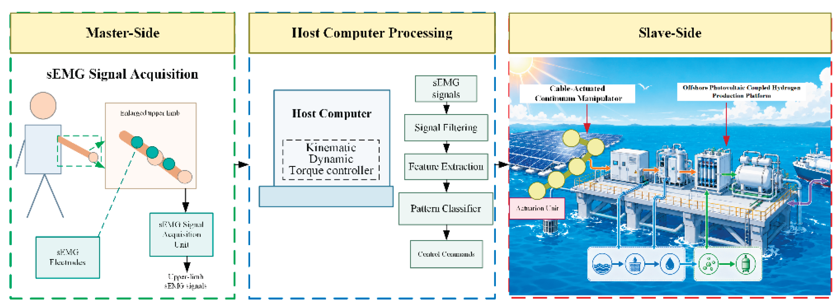
Figure 2.
Four motions completed by the subjects.
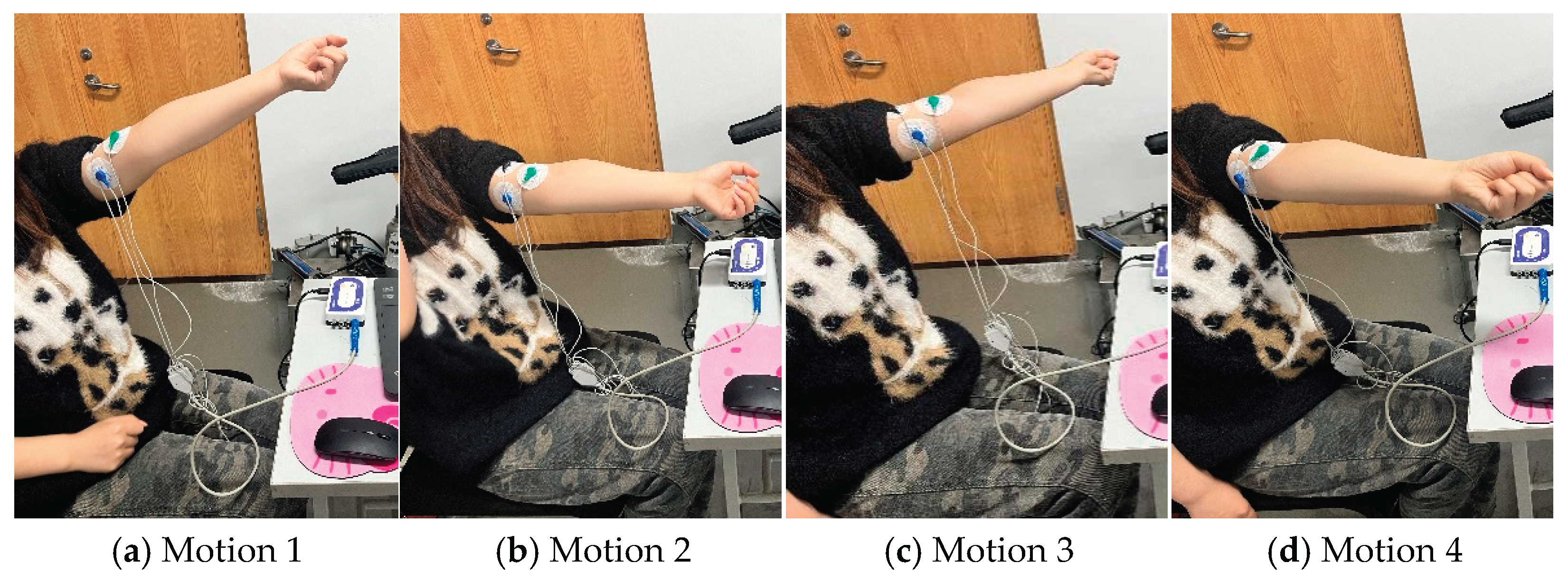
Figure 4.
Waveform comparison results of four movements before and after filtering.
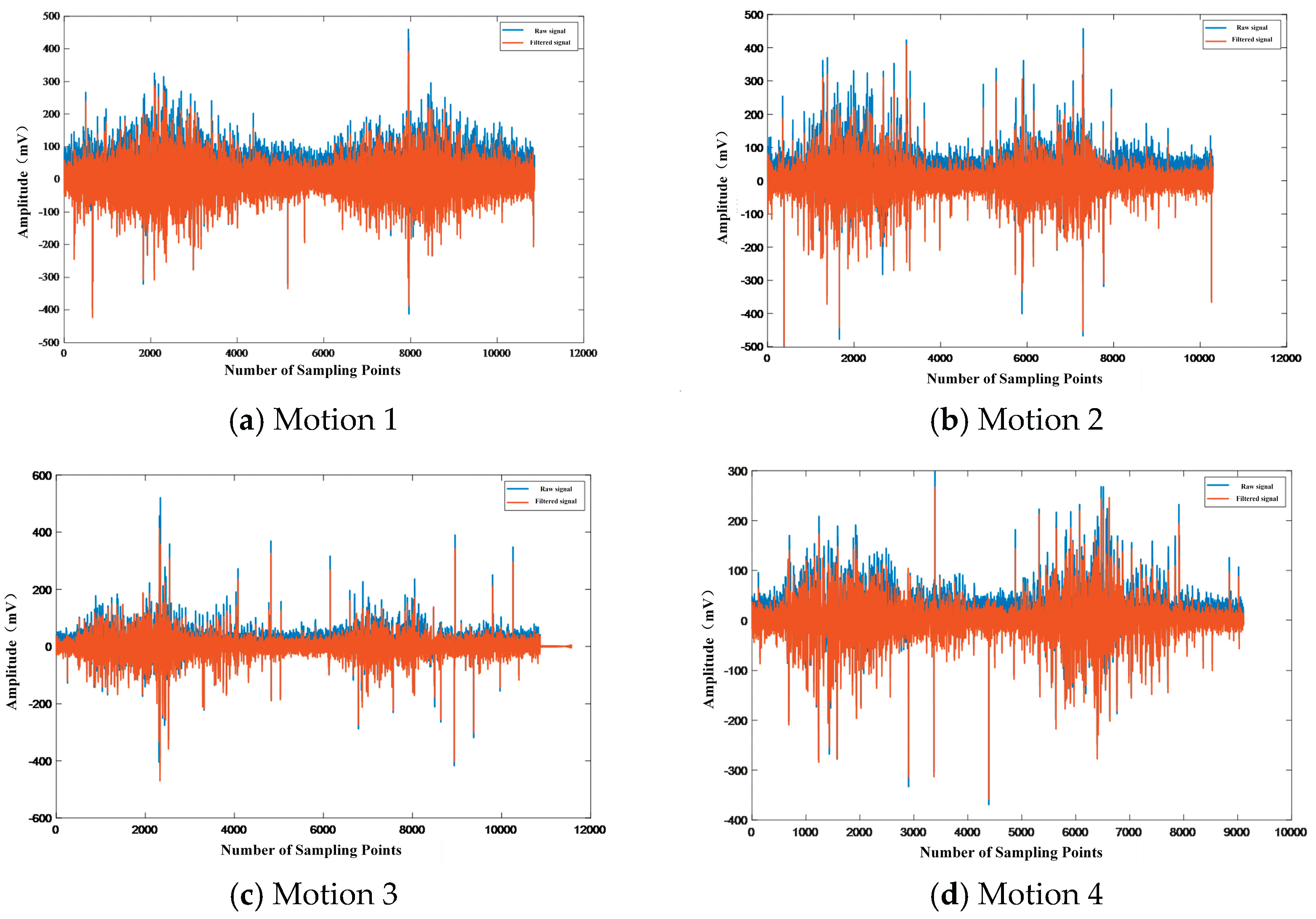
Figure 5.
Frequency distributions of the signals before and after filtering for Motion 1.
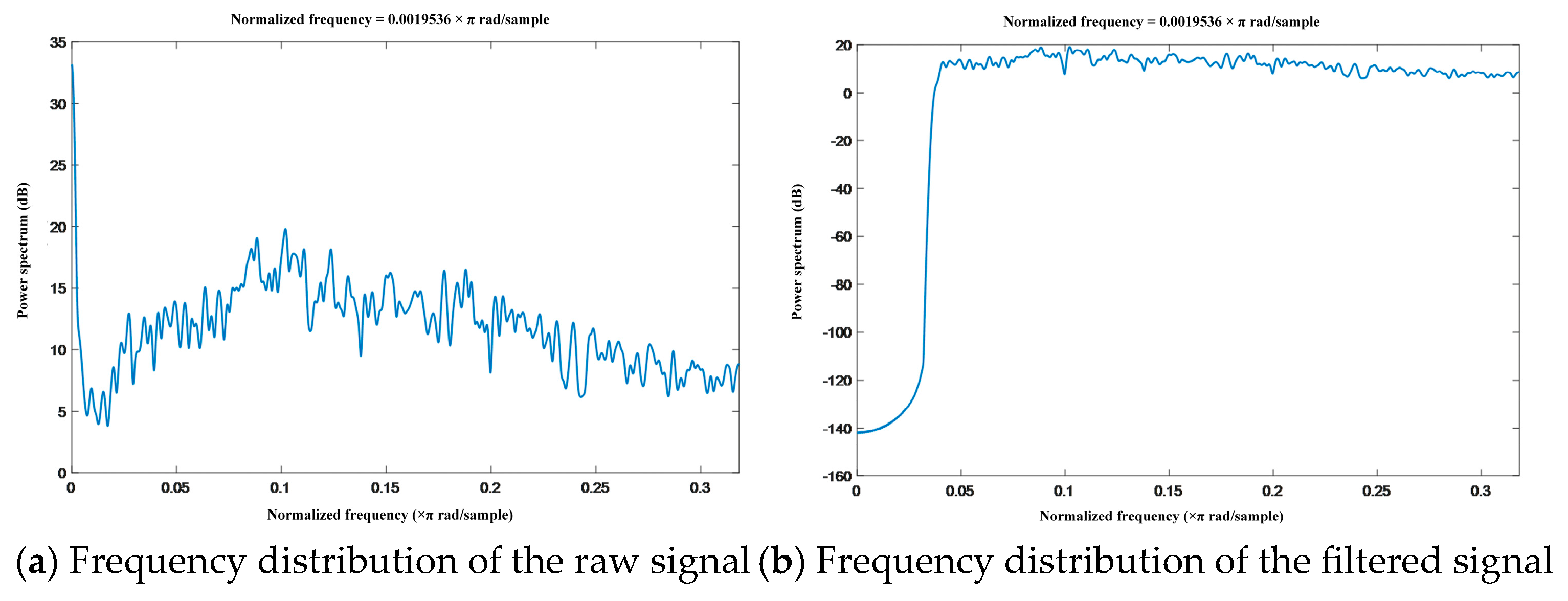
Figure 6.
Frequency distributions of the signals before and after filtering for Motion 2.
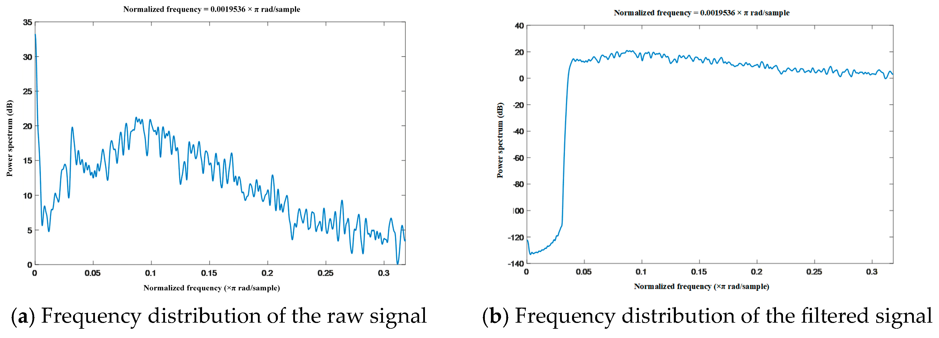
Figure 7.
Frequency distributions of the signals before and after filtering for Motion 3.
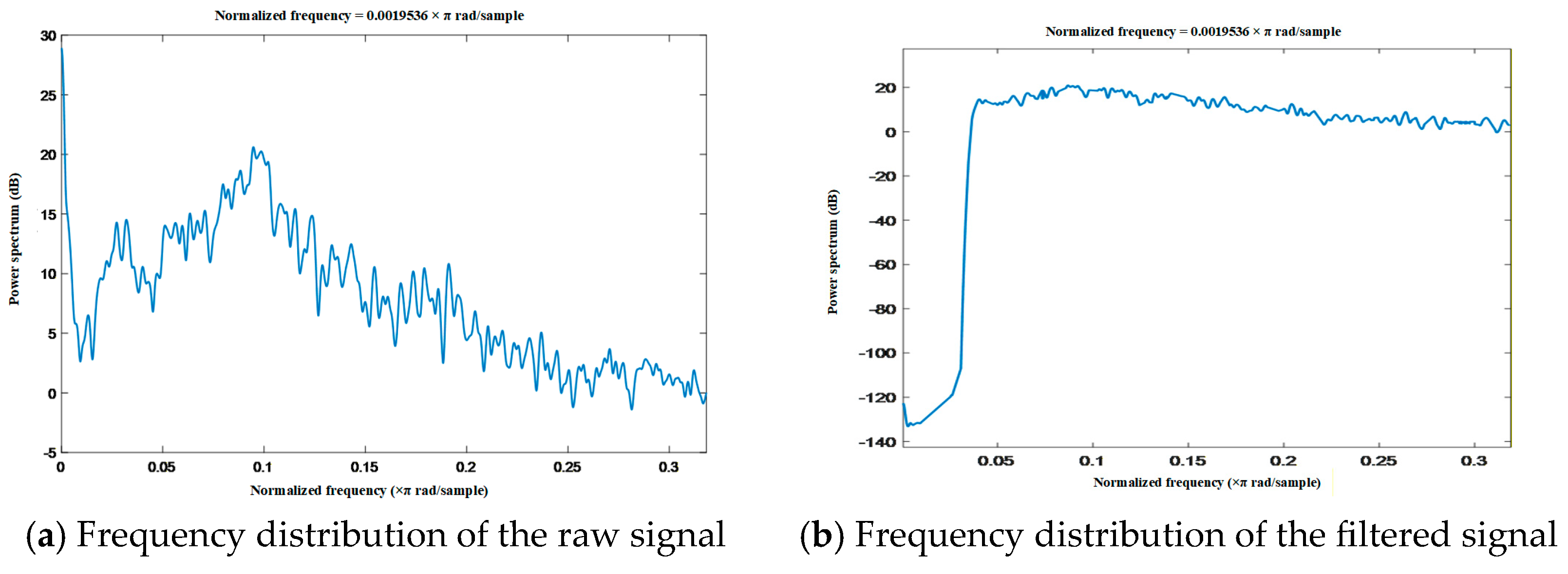
Figure 8.
Frequency distributions of the signals before and after filtering for Motion 4.
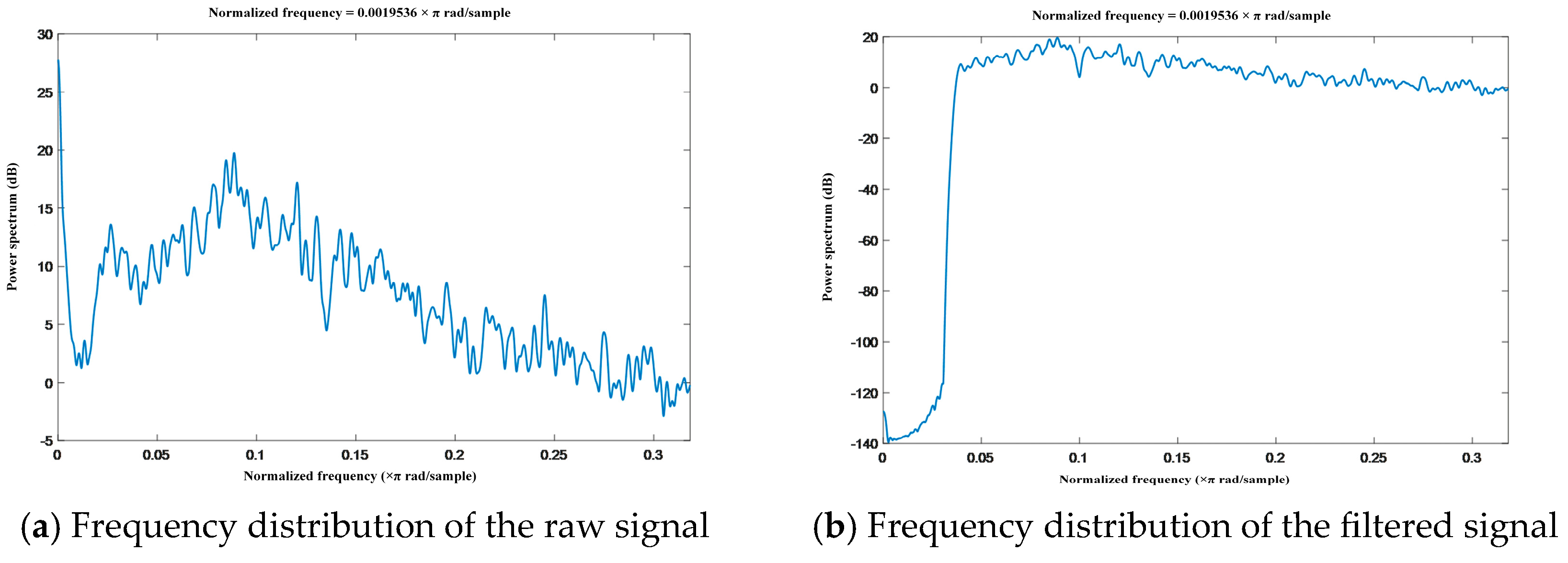
Figure 9.
Time-domain feature extraction results of the biceps brachii.
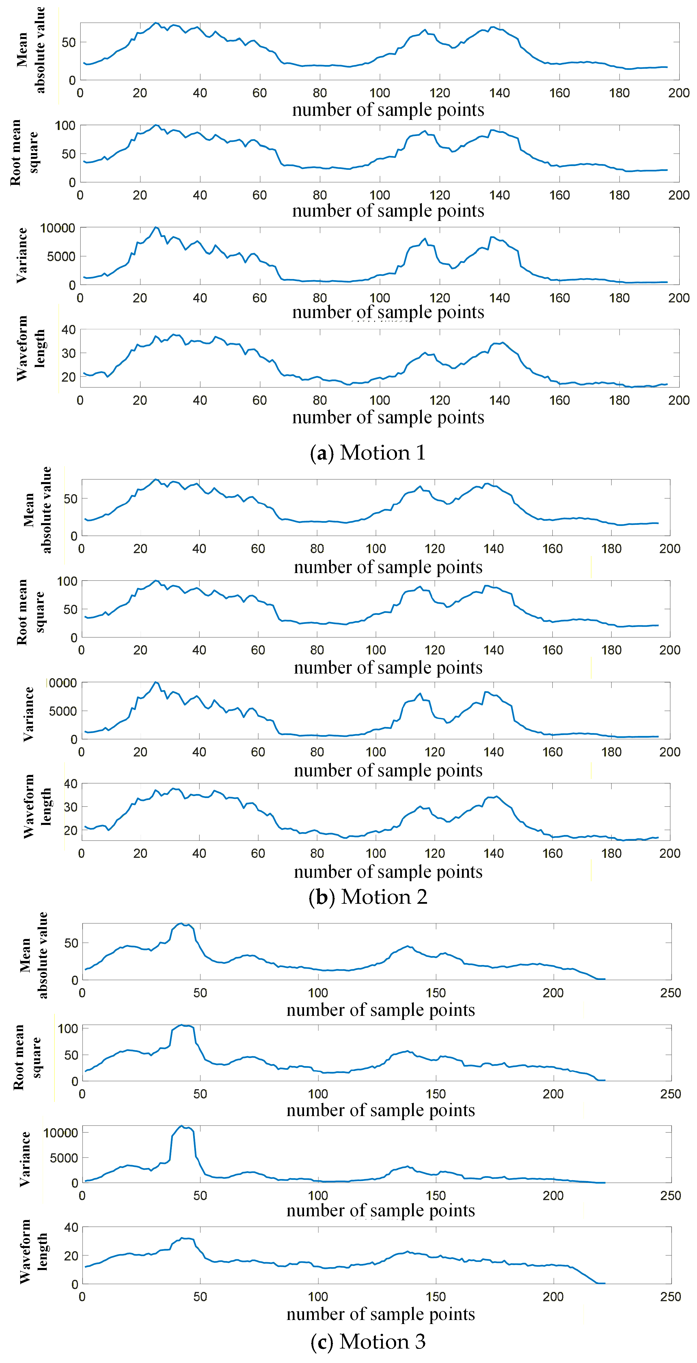
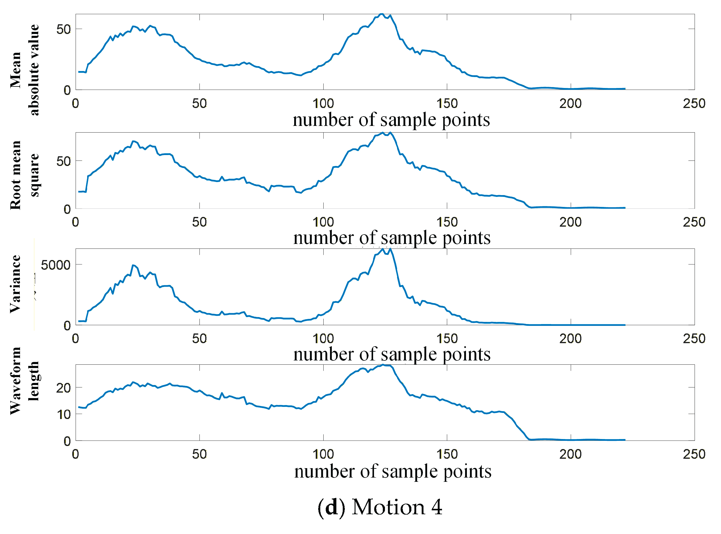
Figure 10.
Flowchart of the GA-BP pattern classifier.
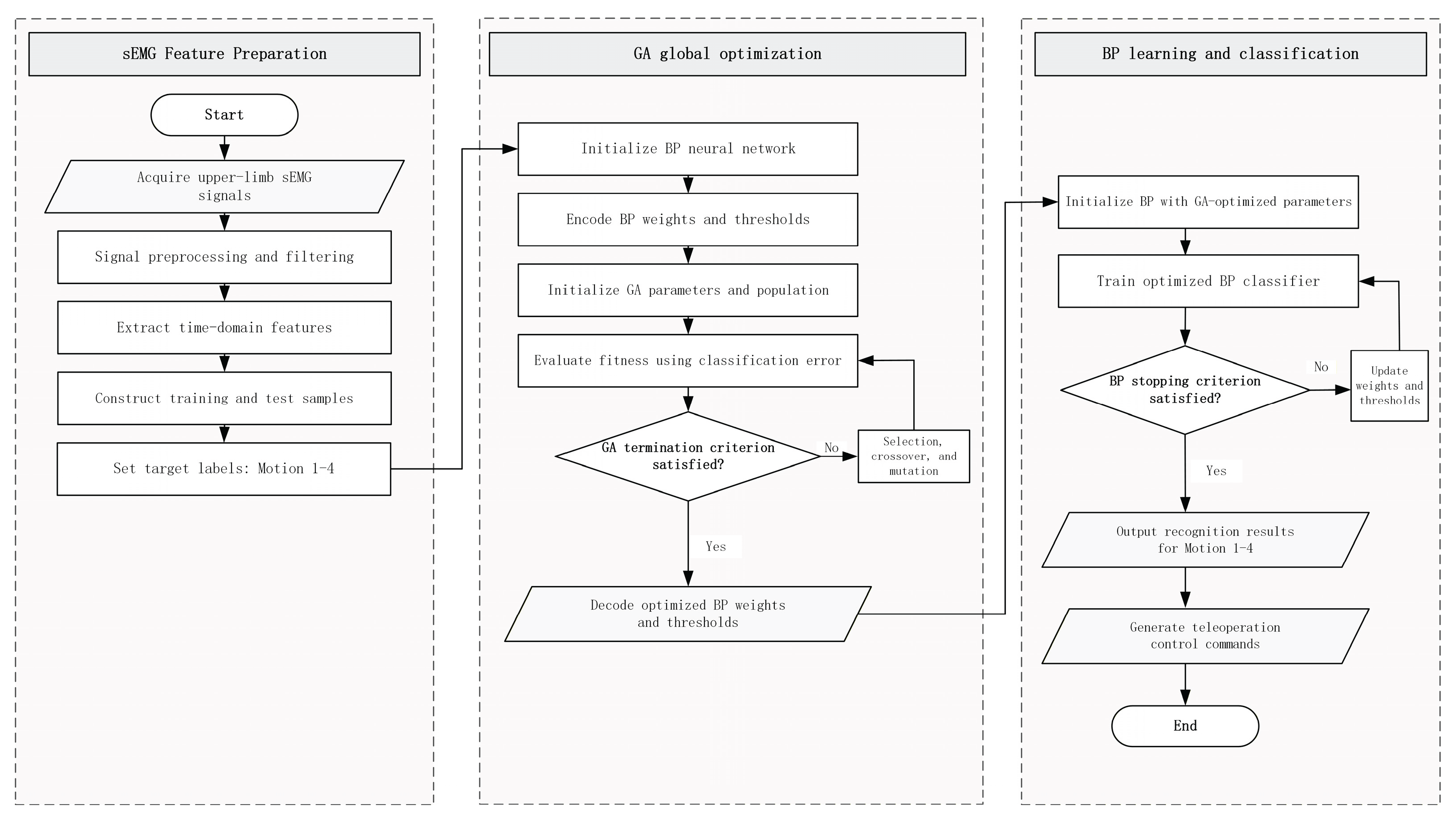
Figure 11.
Classification results of motion signals using the BP neural network model.
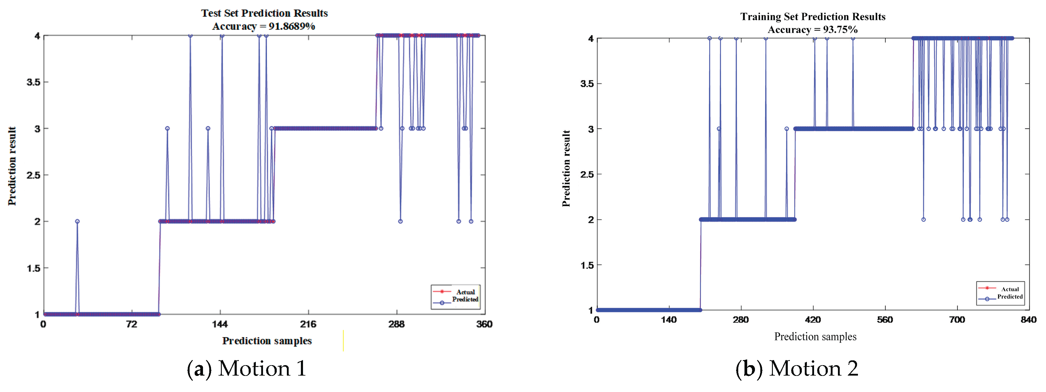
Figure 12.
Classification results of motion signals using the GA-BP pattern classifier.
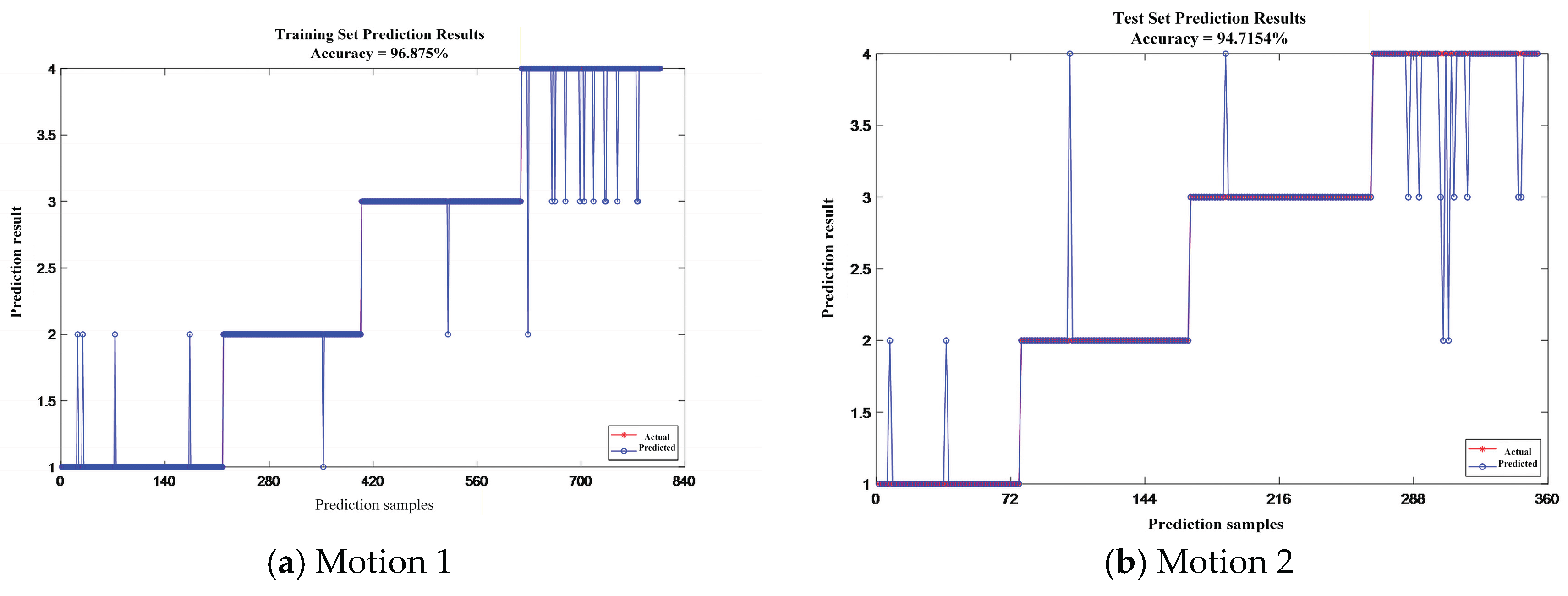
Figure 13.
Structural schematic of the bending deformation of a single-section manipulator.
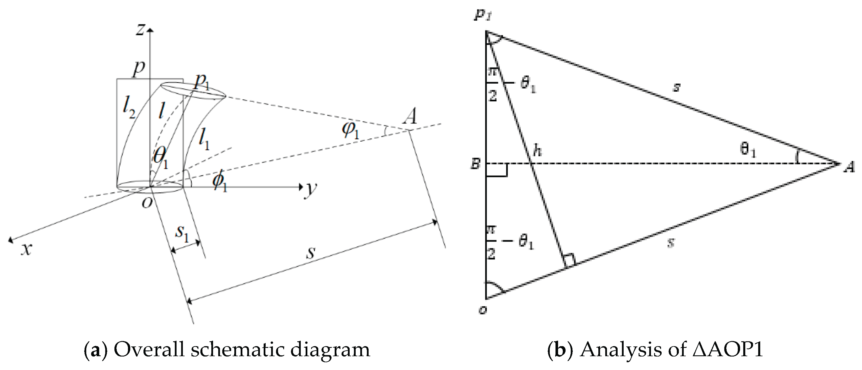
Figure 14.
Establishment of coordinate frames for the cable-driven continuum manipulator.
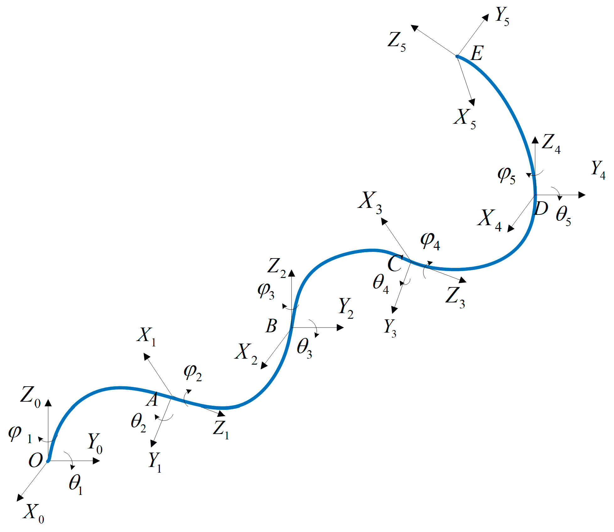
Figure 15.
Kinematic simulation results of the cable-driven continuum manipulator.
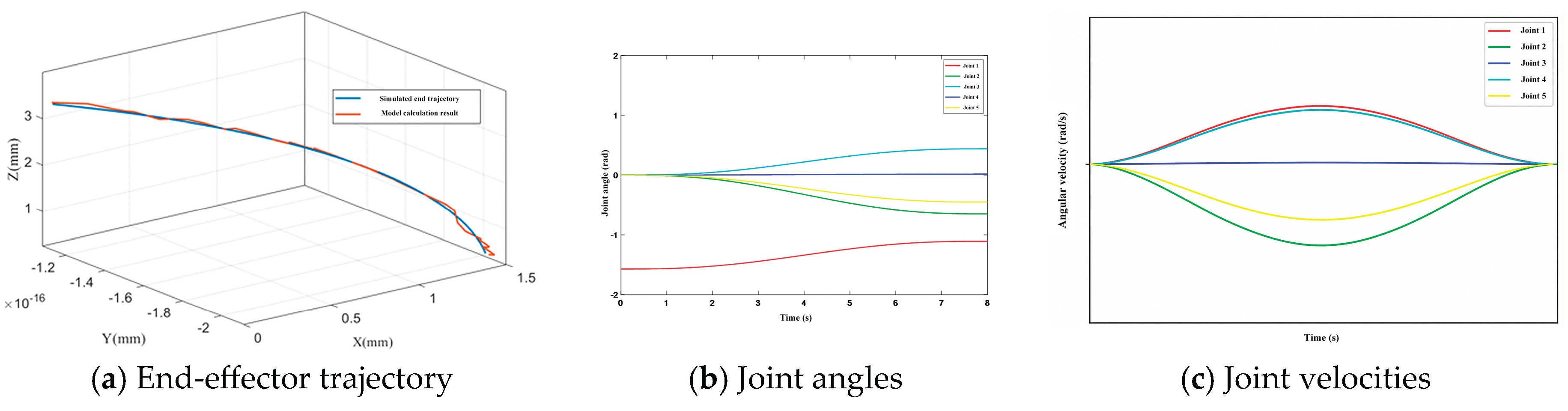
Figure 16.
System simulation model of the torque controller for the cable-driven continuum manipulator.
Figure 16.
System simulation model of the torque controller for the cable-driven continuum manipulator.
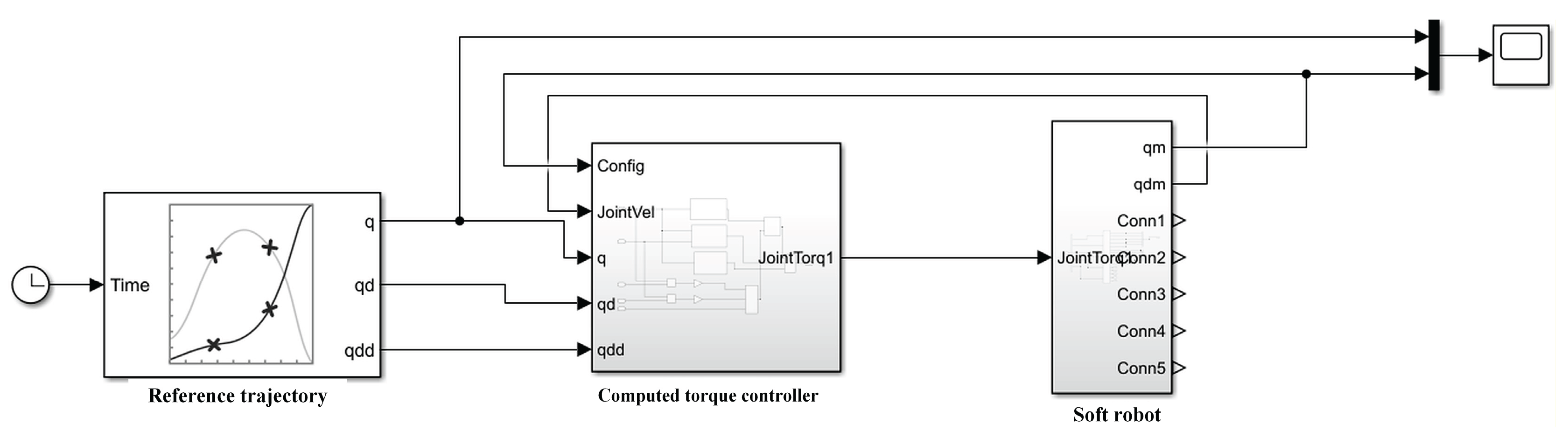
Figure 17.
Comparison of torque control simulation results of the cable-driven continuum manipulator.
Figure 17.
Comparison of torque control simulation results of the cable-driven continuum manipulator.
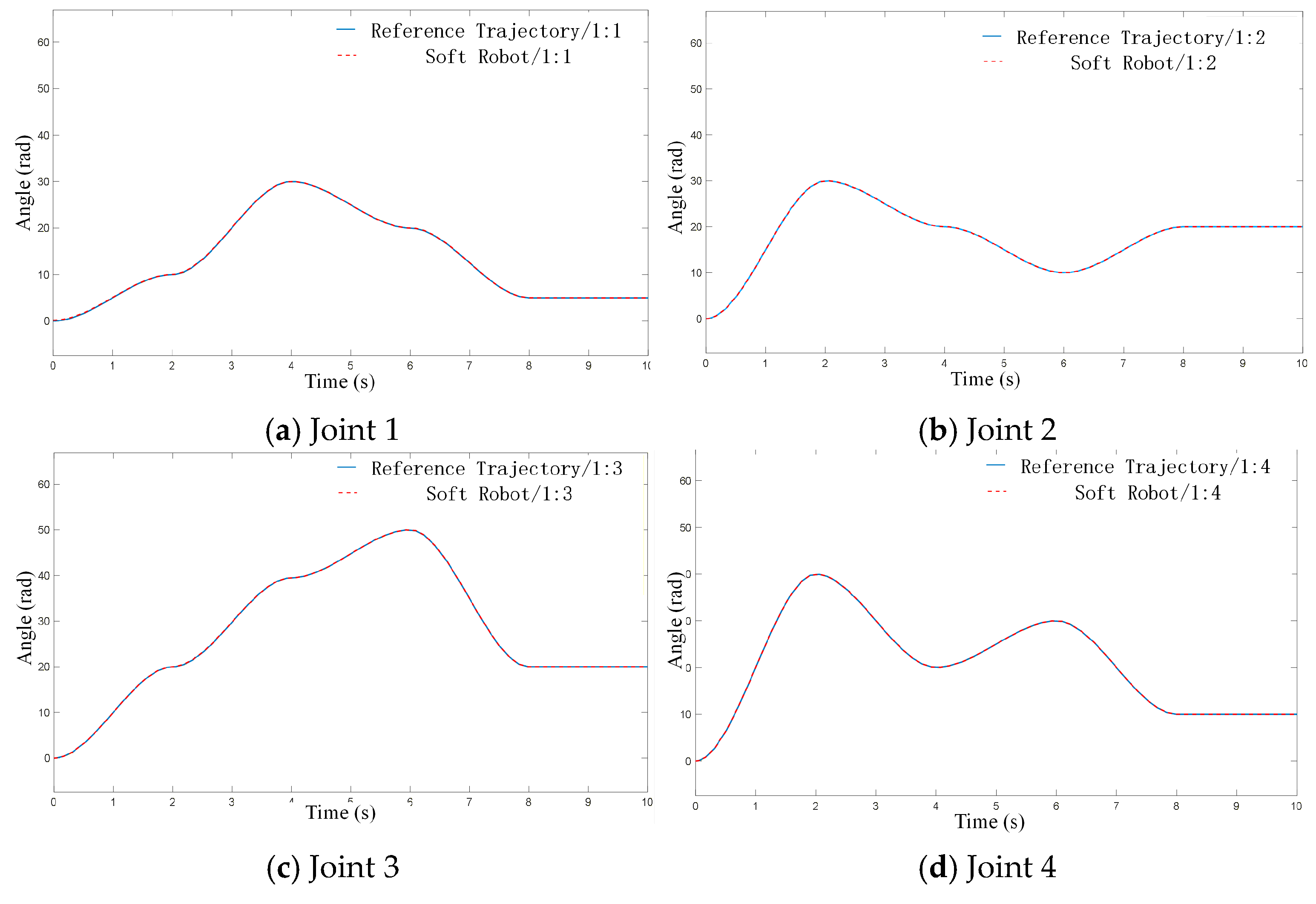
Figure 18.
Experimental system setup.
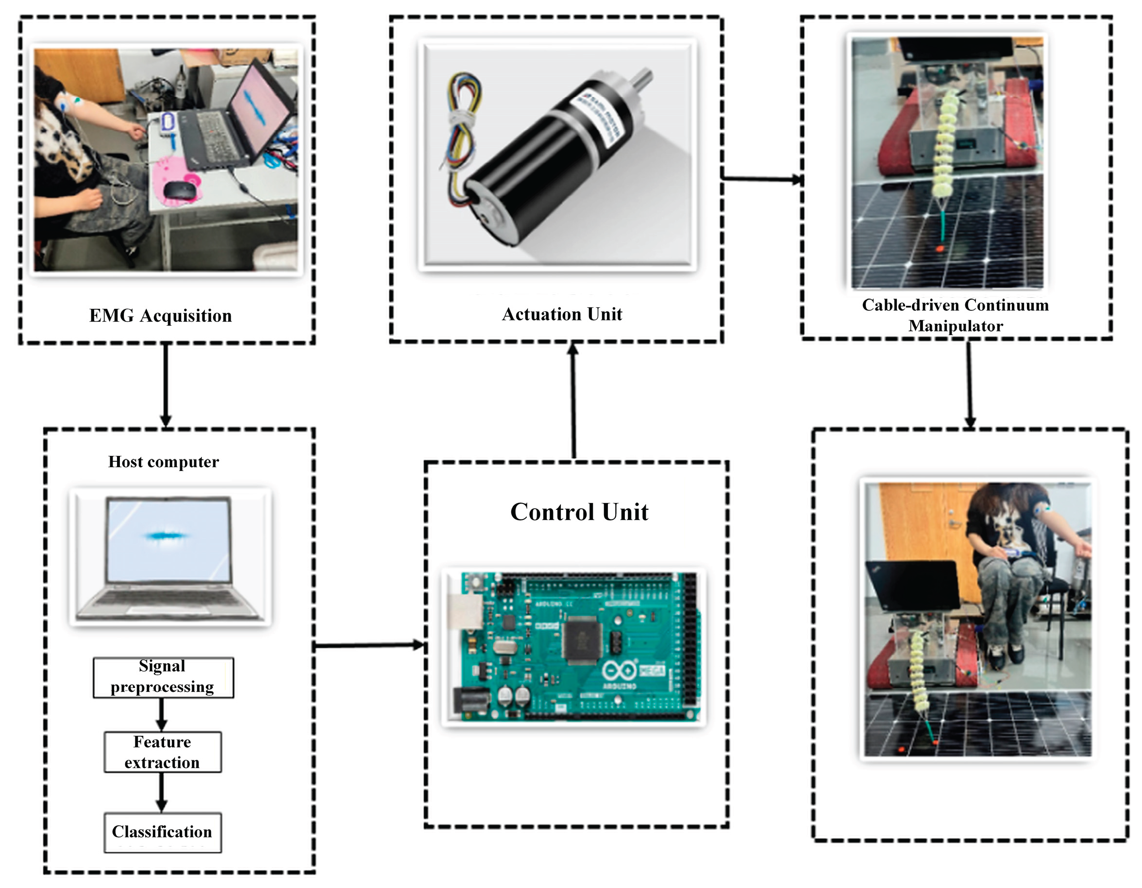
Figure 19.
Experimental validation of single-point trajectory tracking accuracy.
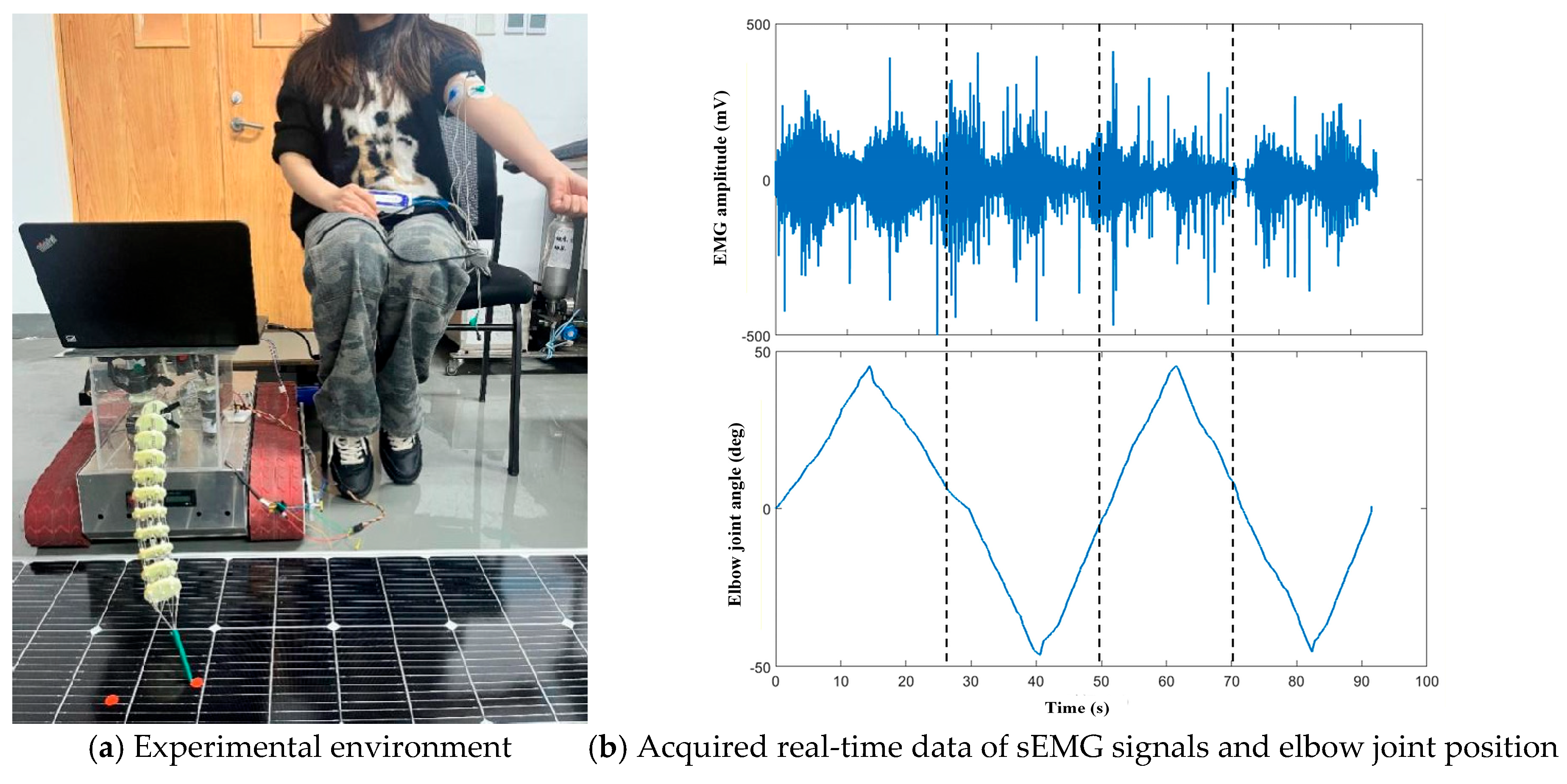
Figure 20.
Experimental results of continuous trajectory tracking accuracy.
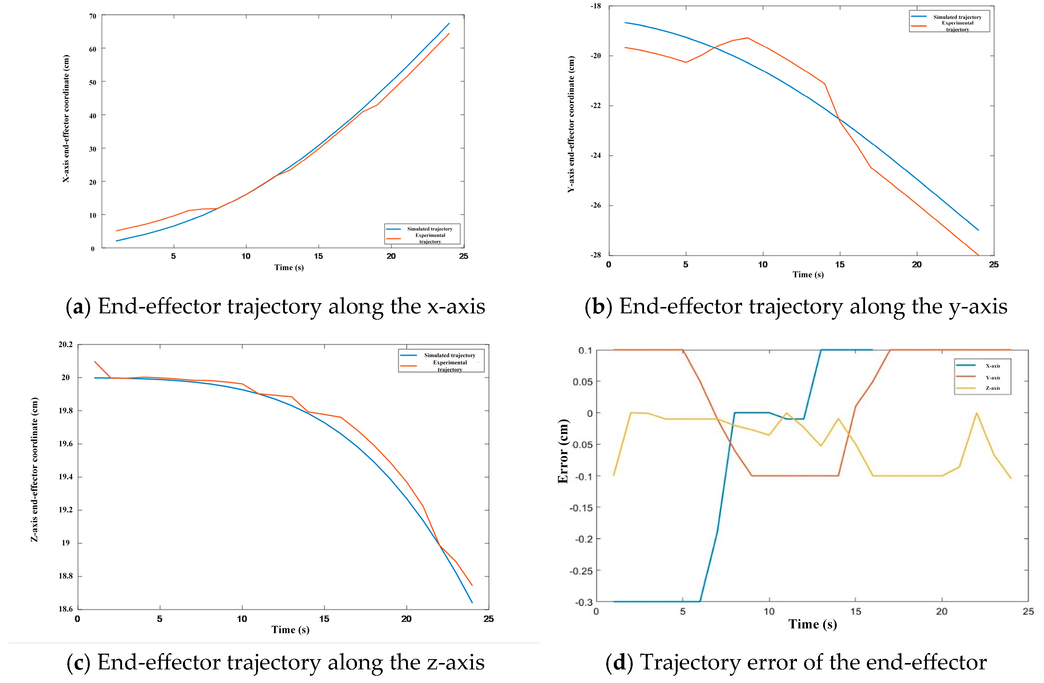
Figure 21.
Position tracking curves for different motions.
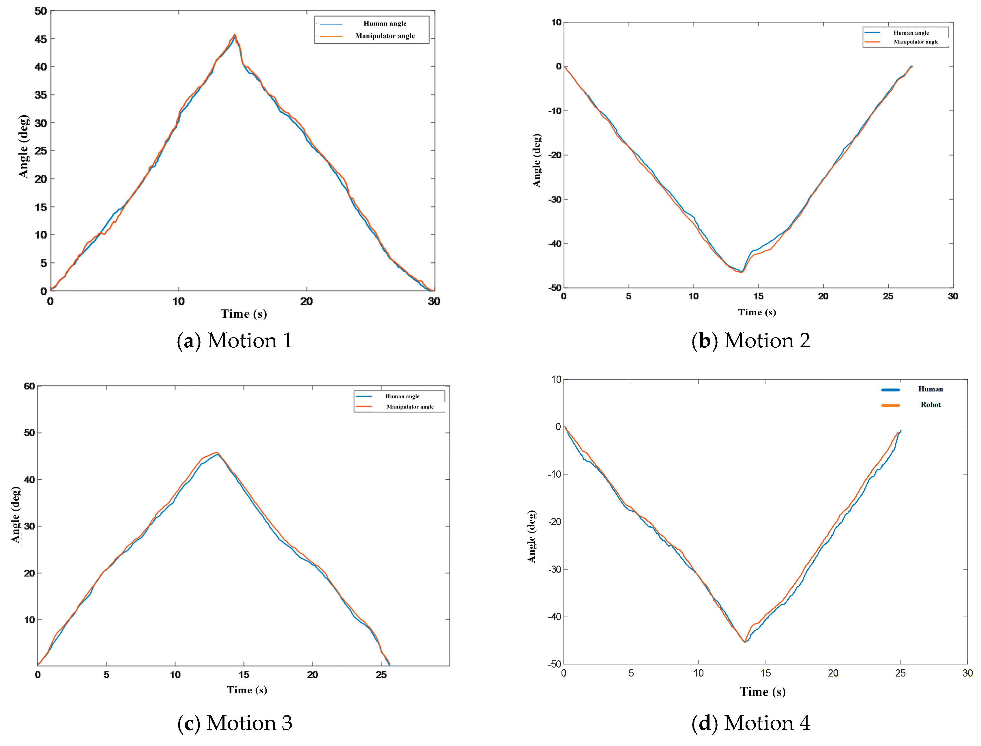

Table 1.
Basic information of the subjects.
| No. | Sex | Height (cm) | Weight (kg) | No. | Sex | Height (cm) | Weight (kg) |
| 1 | M | 174.5 | 74.4 | 6 | F | 167.4 | 60.8 |
| 2 | M | 169.9 | 57.3 | 7 | F | 163.0 | 55.4 |
| 3 | M | 175.6 | 70.6 | 8 | F | 160.1 | 50.6 |
| 4 | M | 176.3 | 68.4 | 9 | F | 167.7 | 64.3 |
| 5 | M | 172.8 | 66.9 | 10 | F | 157.4 | 50.8 |
Table 2.
D-H parameters of the cable-driven continuum manipulator.
| Joint | Variable |
Joint angle (º) |
Link offset (mm) |
Link length (mm) |
Twist angle (º) |
Joint type |
| 1 | θ1 | 0 | 0 | 0 | -pi/2 | 0 |
| 2 | θ2 | pi | 0 | 50 | pi | 0 |
| 3 | θ3 | 0 | 0 | 50 | pi | 0 |
| 4 | θ4 | 0 | 0 | 50 | 0 | 0 |
| 5 | θ5 | 0 | 0 | 50 | 0 | 0 |
Table 3.
Experimental results for validating single-point trajectory tracking accuracy.
| Subject | Arm motion | Number of completed motions | Accuracy | |
| Success | Failure | |||
| 1 | Motion 1 | 19 | 1 | 95% |
| Motion 2 | 19 | 1 | 95% | |
| Motion 3 | 20 | 0 | 100% | |
| Motion 4 | 20 | 0 | 100% | |
| 2 | Motion 1 | 18 | 2 | 90% |
| Motion 2 | 19 | 1 | 95% | |
| Motion 3 | 20 | 0 | 100% | |
| Motion 4 | 19 | 1 | 95% | |
| Subject | Arm motion | Number of completed motions | Accuracy | |
| Success | Failure | |||
| 3 | Motion 1 | 20 | 0 | 100% |
| Motion 2 | 18 | 2 | 90% | |
| Motion 3 | 18 | 2 | 90% | |
| Motion 4 | 20 | 0 | 100% | |
| 4 | Motion 1 | 19 | 1 | 95% |
| Motion 2 | 20 | 0 | 100% | |
| Motion 3 | 18 | 2 | 90% | |
| Motion 4 | 18 | 2 | 90% | |
| 5 | Motion 1 | 19 | 1 | 95% |
| Motion 2 | 18 | 2 | 90% | |
| Motion 3 | 20 | 0 | 100% | |
| Motion 4 | 18 | 2 | 90% | |
Disclaimer/Publisher’s Note: The statements, opinions and data contained in all publications are solely those of the individual author(s) and contributor(s) and not of MDPI and/or the editor(s). MDPI and/or the editor(s) disclaim responsibility for any injury to people or property resulting from any ideas, methods, instructions or products referred to in the content. |
© 2026 by the authors. Licensee MDPI, Basel, Switzerland. This article is an open access article distributed under the terms and conditions of the Creative Commons Attribution (CC BY) license (http://creativecommons.org/licenses/by/4.0/).
Copyright: This open access article is published under a Creative Commons CC BY 4.0 license, which permit the free download, distribution, and reuse, provided that the author and preprint are cited in any reuse.


