
Preprint
Article

This version is not peer-reviewed.

3D‐Printed Geopolymer Composite Truss Beam: Experimental Verification of Manufacturing and Load‐Bearing Capacity in Four‐Point Bending

Submitted:

09 July 2026

Posted:

10 July 2026

You are already at the latest version

Abstract
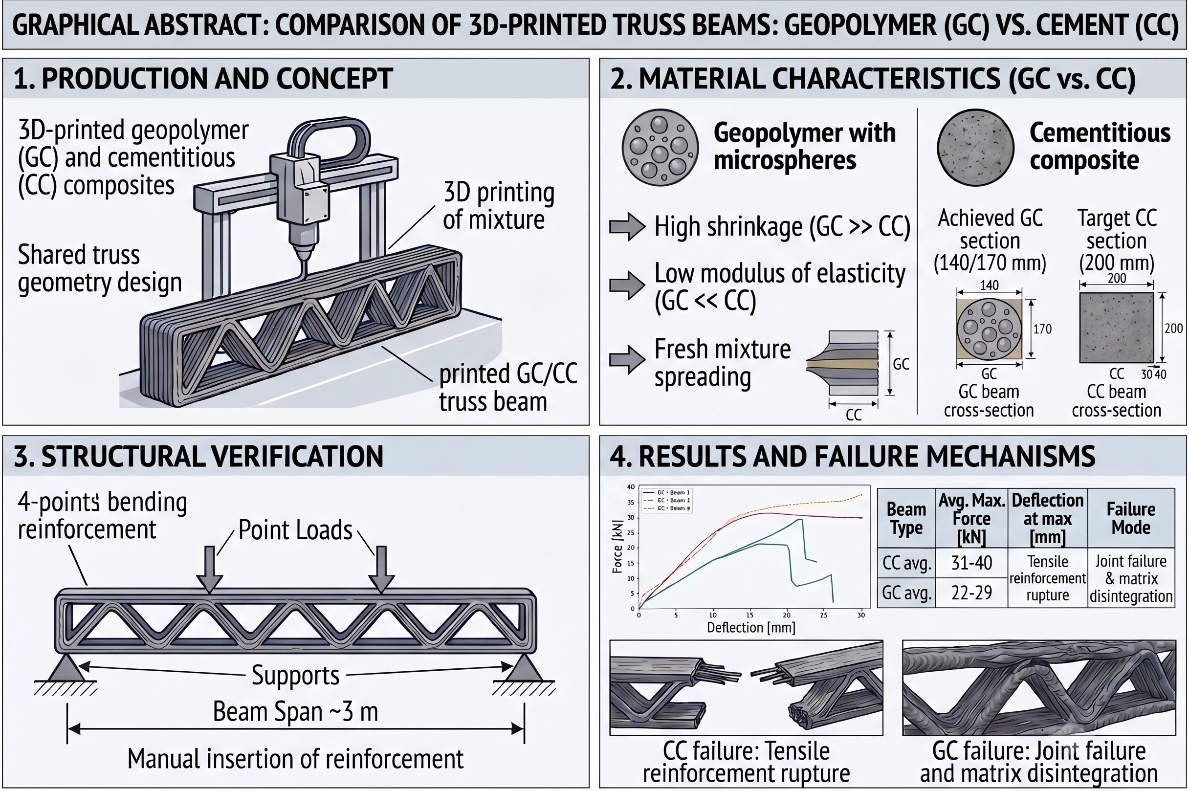
Geopolymers represent a promising material platform for extrusion-based 3D printing; however, current research remains largely focused on mix design, rheology, printability, buildability, and the relationship between process parameters and the resulting microstructure (1–7). This article therefore compares the behaviour of two 3D-printed geopolymer composite truss beams with reference cementitious composite beams developed within the 3D STAR project (8). The geopolymer elements, 2932 mm long, were designed for the same material volume and target geometry as the reference CC element; however, because of mixture spreading, they reached cross-sections of only approximately 140/250 mm and 170/250 mm. The first beam was printed without setting acceleration, while the second was locally treated with a hot-air gun. In four-point bending, the geopolymer beams reached maximum forces of 22 and 29 kN, whereas the reference cementitious beams reached 31 and 40 kN. The CC elements failed by rupture of the tensile reinforcement, while the GC elements failed by joint failure followed by deformation and local disintegration of the composite. The study thus shows that the main difference between the two systems lies not only in the achieved load-bearing capacity, but also in stiffness, the shape of the load-displacement diagrams, and the failure mechanism.
Keywords: 
;  ;  ;  ;  ;  ;  

1. Introduction

The abbreviations GC for geopolymer composite and CC for cementitious composite are used throughout the text. Additive manufacturing with CC and GC is an established direction in construction research. Current literature on GC mainly addresses mix design, rheology, extrudability, buildability, shape stability, interlayer bonding, and the relationship between process parameters and microstructure [1,2,3,4,5,6,7]. The assessment of real structural elements, the effect of layering on load-bearing capacity, and the integration of reinforcement into continuous printing are less unified [6,9,10,11,12,13].
For structural application, the decisive question is whether a load-bearing element can be reliably printed, reinforced, and verified from the material. In truss geometry, the joints, interaction with reinforcement, and preservation of the cross-section during printing are particularly important [9,11,12].
In previous research, a 3D-printed truss floor beam made of CC was developed. In four-point bending, it failed only after rupture of the tensile reinforcement, not by failure of layers or joints [11]. This created a reference framework for verifying the same structural concept using GC.
The GC mixture used in this study was lightweighted with 3M microspheres. These improve printing properties, reduce the sagging of lower layers, and decrease dead load; possible thermal-insulation and fire-resistance benefits were not evaluated in this work. The aim was not to prove the general superiority of GC, but to verify this particular mixture in a reinforced structural element.
The aim was to verify the printing and four-point bending behaviour of a GC beam whose shape was derived from a previously tested CC beam. The text focuses on structural behaviour; material data are provided only for the interpretation of results.
Figure 1. Reference CC truss beam: geometry and layer scheme.
Preprints 222398 g001
Figure 2. Reference CC truss beam: cross-section and reinforcement details.
Preprints 222398 g002

2. Materials and Methods

2.1. Research Concept

The research distinguishes between the material level (mixture composition, fresh behaviour, mechanical properties, and printing limits) and the structural level (manufacturing, reinforcement, and loading of a real beam).
This article focuses on the structural level. The material characteristics serve only to explain the geometry, printing strategy, and failure of the elements. This focus responds to the predominance of studies on mixtures and fresh behaviour compared with the smaller number of structural demonstrators [2,3,4,5,6,7].

2.2. GC Mixture Used

A GC mixture with which the team had the greatest previous experience was used. Its composition, preparation, and comparison of technological, density, and mechanical parameters of GC and CC are given in Table 1, Table 2 and Table 3.
The geometry of test specimens, mixing, and testing conditions are given in Table 1.

2.3. Reference CC Beam

The reference CC beam was taken from the 3D STAR project [13]: length 2932 mm, cross-section 200/250 mm, bead width 30 mm, strength approximately C40/50, manually inserted B500B reinforcement, and chemical setting acceleration with 17% aluminium sulfate in the printing technology.
The comparative parameters are shown in Table 2 and Table 3; the load-displacement diagrams are given in Section 3.2 and in Figure 7.

2.4. Geometry, Printing, and Testing of GC Beams

Two GC beams were printed with the same design volume of mixture and the same target geometry as the CC reference. Printing and manual insertion of reinforcement followed the same drawings.
The printing design assumed a height during printing of 200 mm and a bead width of 30 mm. Spreading of the fresh mixture reduced the achieved height to 140 mm for the first beam and 170 mm for the second; the average bead width increased to approximately 40 and 35 mm, respectively.
Printing proceeded at approximately 1.3–2.9 m/min for the first beam and 0.9–2.1 m/min for the second; the speed was continuously adjusted according to the fluidity of the mixture. The first beam was printed without hot-air acceleration. For the second beam, each layer was locally heated with a hot-air gun at maximum power before the next layer was deposited. The effect was limited, especially compared with earlier trials using a 6 mm bead.
Table 4. Printing parameters of the GC beams and the reference CC element.
Parameter GC–1 GC–2 Ref. CC Note
Nozzle diameter [mm] 15 25
Approx. speed [m/min] 1.3–2.9 0.9–2.1 adjusted to mixture fluidity
Nominal height [mm] 200 200 200 after rotation: resulting section width
Actual height [mm] 140 170 200 effect of mixture spreading
Required bead [mm] 30 30 30 same as reference CC element
Average bead [mm] 40 35 30
Printing time [min] 120 150
Acceleration during printing no hot air, max. power chemical accelerator part of CC 3D STAR technology [1]
Figure 4. Printing of the second GC truss beam in the laboratory.
Preprints 222398 g003
Reinforcement layouts for the achieved widths of 140 and 170 mm are shown in Figure 5 and Figure 6.

3. Results

3.1. Printing and Shape Quality of the Elements

The production of the GC beams verified the printing of a real, nearly three-metre-long reinforced element. At the same time, the insufficient shape stability of the mixture was confirmed.
The first beam had a cross-section of 140/250 mm and a bead width of approximately 40 mm. The second reached 170/250 mm with a bead width of approximately 35 mm. The comparison with CC is therefore also a comparison of different geometric precision.

3.2. Load-Displacement Diagrams and Load-Bearing Capacity

Figure 7. Load-displacement diagrams of CC and GC beams.
Preprints 222398 g006
GC exhibited a lower ultimate force, lower stiffness, and a steeper post-peak drop. After reinforcement yielding, CC retained a reserve of load-bearing capacity up to reinforcement rupture; GC failed by joint failure and loss of stability.

3.3. Failure Mode

The CC beams failed by rupture of the tensile reinforcement in the bottom chord; the layers and joints remained functional. The structure therefore utilised the reinforcement up to the ultimate limit state.
In the GC beams, the reinforcement did not rupture. The decisive process was joint failure, deformation, and local disintegration of the matrix, probably due to the combined effect of lower strength, low modulus of elasticity, higher shrinkage, weaker bond to reinforcement, and printing deviations.
Figure 8. Loading test of the GC truss beam in the laboratory.
Preprints 222398 g007
Figure 9. Detail of joint failure in the top chord region.
Preprints 222398 g008
Figure 10. Detail of joint failure in the bottom chord region.
Preprints 222398 g009
Figure 11. Bottom chord fragment.
Preprints 222398 g010
Table 5. Summary of the results of the loading tests of the truss beams.
Beam Section [mm] Bead [mm] Failure Force at plast. onset [kN] Max. force [kN] Deflection at plast. onset [mm]
CC–1 200/250 30 Rebar rupture 30 40 13
CC–2 200/250 30 Rebar rupture 25 31 12
GC–1 140/250 40 GC failure 15 22 8
GC–2 170/250 35 GC failure 15 29 8
CC avg. 200/250 30 Rebar rupture 27.5 35.5 12.5
GC avg. 155/250 37.5 GC joint failure 15.0 25.5 8.0
GC/CC [%] 54.5 71.8 64.0

4. Discussion

4.1. What the Results Demonstrate

The experiment verified the printing, reinforcement, and loading of a GC beam at a scale of almost 3 m. Its contribution is the comparison of the structural response with the CC reference.
The data show the influence of GC/CC differences on stiffness, load-bearing capacity, load-displacement diagrams, and failure mode; they do not constitute a universal design recommendation.

4.2. Why the Difference in Load-Bearing Capacity and Stiffness Cannot Be Reduced Only to Compressive Strength

The lower load-bearing capacity and earlier nonlinearity of GC cannot be explained by a single strength value. At 28 days, GC reached approximately 41% of the CC compressive strength, 85% of the flexural tensile strength, 12% of the static modulus, and more than fourteen times the shrinkage. The decisive factor was the combination of low stiffness, high shrinkage, geometric inaccuracy, and weakened joints.
This conclusion is consistent with the literature on 3D printing of GC: mechanical performance is determined not only by strength, but also by the rheological window, structuration after extrusion, interlayer bonding, anisotropy, and sensitivity to process conditions [1,2,3,4,5,6,7]. Zhang et al. show that open time and the rheological window affect print quality, strength, and anisotropy [14]. We therefore interpret the failure mode as the combined effect of material and process factors.

4.3. Evaluation of the Role of Reinforcement

For the achieved properties of GC, the bar reinforcement was rather oversized: at 22 and 29 kN it did not rupture, whereas in CC the tensile reinforcement ruptured at 31 and 40 kN.
The result does not imply that steel reinforcement is unsuitable. For a GC matrix with the given stiffness, shrinkage, and geometric precision, however, the reinforcement concept cannot be adopted from CC without modification. In digitally manufactured CC and GC elements, reinforcement must be understood as part of the manufacturing system, not merely as an inserted element from conventional reinforced concrete [9,10,11,12].

4.4. Technological Limit: Setting Acceleration After Layer Deposition

The practical limit was not extrusion, but strengthening after layer deposition. In the second beam, hot-air heating improved the process only to a limited extent and did not replace reproducible setting acceleration.
Further development should focus on setting acceleration after layer deposition: dosing an accelerator immediately before extrusion, similarly to CC in the 3D STAR project [13], or uniformly heating the layer using infrared or microwave radiation [4,15]. The aim is not a faster mixture throughout the entire system, but a combination of formulation and process that provides workability in the equipment and rapid strengthening after deposition.

4.5. Material-Technological Implications of the Results

The causes of failure were both material and technological: low modulus of elasticity, high shrinkage, enlarged bead, unachieved cross-section, and variable joint quality.
These relationships are summarised in Table 1, Table 2 and Table 3 and Figure 7.

5. Conclusions

  • A GC beam 2.93 m long can be 3D printed, reinforced, and loaded in four-point bending.
  • The GC beams reached maximum forces of 22 and 29 kN; the CC references reached 31 and 40 kN.
  • Nonlinearity occurred in GC at approximately 15 kN and in CC at 25–30 kN; CC had higher stiffness and a reserve of load-bearing capacity after reinforcement yielding.
  • CC failed by rupture of the tensile reinforcement; GC failed by joint failure, deformation, and local disintegration of the matrix.
  • The difference cannot be explained only by compressive strength: at 28 days, GC had approximately 41% of the CC compressive strength, 85% of the flexural tensile strength, 12% of the static modulus, and more than fourteen times the shrinkage.
  • The bar reinforcement was oversized relative to the GC matrix; it was not fully activated at failure.
  • The main limit was the shape stability of the fresh mixture and the absence of robust setting acceleration after layer deposition.
  • The study provides structural verification of a GC beam and defines the limits of large-scale printing of this mixture.

Author Contributions

Conceptualization, Stoklasa and Bureš; measurement methodology, Stoklasa, Čítek and Bureš; validation, Bureš and Čítek; formal analysis, Stoklasa; experimental work, primarily Stoklasa, with contributions from Piotr Loś, Melter and Čítek; GC mixture development and preparation, Katarzyna Ewa Loś and Piotr Loś; resources, Stoklasa, Čítek and Zelený; data curation, Stoklasa; writing—original draft preparation, Stoklasa; writing—review and editing, Stoklasa, Bureš and Čítek; visualization, Stoklasa; supervision, Bureš and Čítek; project administration, Stoklasa; funding acquisition, Stoklasa. Stoklasa led and organized the project, coordinated the experimental part, performed the printing and carried out the tests, curated the data, prepared the visualizations, administered the project and prepared the original manuscript draft. Bureš supervised the scientific level of the project and provided expert consultation and support during the evaluation of the results. Melter contributed to setting up the printing robot in order to achieve the best possible result with the selected GC. Čítek supervised and contributed to the development of the testing methodology, both for the four-point bending tests and for the mechanical characterization of the material. Zelený provided modifications to the technological equipment and its optimization for GC printing. Katarzyna Ewa Loś and Piotr Loś optimized, mixed and developed the GC mixture. All authors have read and agreed to the published version of the manuscript.

Funding

This research was supported by the SGS-2025 programme at the Faculty of Arts and Architecture, Technical University of Liberec. Personnel contributions of collaborating individuals and transport costs were covered from the corresponding author’s own resources. Most material costs were covered through an in-kind material donation from the Faculty of Mechanical Engineering, Technical University of Liberec; several special additives were purchased from the corresponding author’s own resources. Additionally, the manuscript was funded by the University of Kalisz.

Acknowledgments

The authors gratefully acknowledge the 3D STAR project for providing the technological, methodological, personnel, and machine infrastructure used in this work, in particular the support of the Klokner Institute of the Czech Technical University in Prague. The authors also thank the Faculty of Mechanical Engineering, Technical University of Liberec, for providing materials for printing.

Declaration of Generative AI and AI-Assisted Technologies in the Writing Process

During the preparation of this manuscript, generative artificial intelligence (AI) tools were used to support draft text generation, stylistic editing, proofreading, and translation. The AI-assisted outputs were subsequently reviewed, edited, and revised by the corresponding author, and all authors take responsibility for the final content of the manuscript.

Conflicts of Interest

The authors declare no conflict of interest.

References

  1. PANDA, B.; TAN, M.J. Experimental study on mix proportion and fresh properties of fly ash based geopolymer for 3D concrete printing. Ceram. Int. 2018, Vol. 44, 10258–10265. [Google Scholar] [CrossRef]
  2. ZHONG, H.; ZHANG, M. 3D printing geopolymers: A review. Cem. Concr. Compos. 2022, Vol. 128, 104455. [Google Scholar] [CrossRef]
  3. RICCIOTTI, L.; APICELLA, A.; PERROTTA, V.; AVERSA, R. Geopolymer Materials for Extrusion-Based 3D-Printing: A Review. Polymers 2023, Vol. 15, 4688. [Google Scholar] [CrossRef] [PubMed]
  4. BARVE, P.B.; BAHRAMI, A.A.; SHAH, S.S. Geopolymer 3D printing: a comprehensive review on rheological and structural performance assessment, printing process parameters, and microstructure. Front. Mater. 2023, Vol. 10, 1241869. [Google Scholar] [CrossRef]
  5. SHILAR, F.A.; GANACHARI, S.V.; PATIL, V.B.; BHOJARAJA, B.E.; YUNUS KHAN, T.M.; ALMAKAYEEL, N. A review of 3D printing of geopolymer composites for structural and functional applications. Constr. Build. Mater. 2023, Vol. 400, 132869. [Google Scholar] [CrossRef]
  6. MISHRA, J.; BABAFEMI, A.J.; COMBRINCC, R. Limitations and Research Priorities in 3D-Printed Geopolymer Concrete: A Perspective Contribution. Ceramics 2025, Vol. 8, 47. [Google Scholar] [CrossRef]
  7. TANG, J.; WANG, Z.; GAO, D.; YANG, L.; ZHU, H.; ZHAO, L.; LI, Z. Research progress on 3D printed geopolymer concrete. J. Mater. Sci. 2025, Vol. 60, 22559–22594. [Google Scholar] [CrossRef]
  8. ZELENÝ, Petr; SUCHOMEL, Jiří; BUREŠ, Vladimír; ČÍTEK, David; MELTER, Oto; BELDA, Květoslav; BERA, Leoš; BURGETOVÁ, Eva; BROUŠEK, Josef; DIBLÍK, Martin; GABRIEL, Michael; HUDKA, Lukáš; HURTIG, Karel; HVÍZDAL, Aleš; JEDELE, Libor; KAJZR, Daniel; KELLER, Petr; KOLÁŘ, Milan; KOLÍSKO JIŘÍ, K.O.P.R.N.I.C.C.Ý. J.A.N.; KUBÍN, Jiří; MENDŘICCÝ, Robert; MYSLIVEC, Tomáš; NOVÁK, Ondřej; PETR, Tomáš; BALDA, Vladimír; VOŽENÍLEK, Robert; ZÁDA, Václav; RAFTL, Jindřich. 3D STAR: 3D printing in construction and architecture  . In Online; Technická univerzita v Liberci, 2022; Available online: https://publi.cz/download/publication/2590?online=1ISBN 978-80-7494-643-1.
  9. LIM, J.H.; PANDA, B.; PHAM, Q.-C. Improving flexural characteristics of 3D printed geopolymer composites with in-process steel cable reinforcement. Constr. Build. Mater. 2018, Vol. 178, 32–41. [Google Scholar] [CrossRef]
  10. LI, Z.; WANG, L.; MA, G. Mechanical improvement of continuous steel microcable reinforced geopolymer composites for 3D printing subjected to different loading conditions. Compos. Part B Eng. 2020, Vol. 187, 107796. [Google Scholar] [CrossRef]
  11. GEBHARD, L.; MATA-FALCÓN, J.; ANTON, A.; DILLENBURGER, B.; KAUFMANN, W. Structural behaviour of 3D printed concrete beams with various reinforcement strategies. Eng. Struct. 2021, Vol. 240, 112380. [Google Scholar] [CrossRef]
  12. MENNA, C.; MATA-FALCÓN, J.; BOS, F.P.; VANTYGHEM, G.; FERRARA, L.; ASPRONE, D.; SALET, T.; KAUFMANN, W. Opportunities and challenges for structural engineering of digitally fabricated concrete. Cem. Concr. Res. 2020, Vol. 133, 106079. [Google Scholar] [CrossRef]
  13. MORTADA, Y.; HAMMOUD, A.; MASOUD, L.; WYRZYKOWSKI, M.; SIRTOLI, D.; LURA, P.; MANSOOR, B.; MASAD, E. 3D Printable Ca(OH)2-based geopolymer concrete with steel fiber reinforcement. Mater. Struct. 2025, Vol. 58, 73. [Google Scholar] [CrossRef]
  14. ZHANG, Haiyan; GAN; Zhenxian; CHEN, Feihao; CHEN, Baixi. Printability and Mechanical Performance of 3D Printable Geopolymer Concrete with Barium Chloride, Tartaric Acid, Sucrose, and Sodium Tripolyphosphate. J. Adv. Concr. Technol. 2026, Vol. 24(no. 3), 160–173. [Google Scholar] [CrossRef]
  15. MUTHUKRISHNAN, S.; RAMAKRISHNAN, S.; SANJAYAN, J. Effect of microwave heating on interlayer bonding and buildability of geopolymer 3D concrete printing. Constr. Build. Mater. 2020, Vol. 265, 120786. [Google Scholar] [CrossRef]
Figure 5. GC beam reinforcement, 140 mm.
Preprints 222398 g004
Figure 6. GC beam reinforcement, 170 mm.
Preprints 222398 g005
Table 1. Composition and preparation of the GC mixture used.
Component Ratio [-]
Baucid 1.00
Water glass 0.90
Carbon fibres 0.01
Cellulose 0.01
3M microspheres 0.04
Graphite 0.05
Agar 0.005
Xanthan gum 0.005
Anhydrite 0.005
Mixing method and equipment industrial dough mixer; minimum experimental batch of 50 kg of wet mixture
Specimens and conditions flexure/modulus/shrinkage: approx. 40 × 40 × 160 mm; compression: approx. 100 mm cubes; shrinkage: 20 ± 1 °C, RH 50 ± 5%
Table 2. Technological and density characteristics of GC and CC.
Parameter GC CC
Mixing time approx. 45 min
Workability after mixing approx. 60 min + approx. 30 min conditionally
Setting-acceleration method without chemical accelerator; second beam locally hot air chemical accelerator: 17% aluminium sulfate in the 3D STAR technology [13]
Dry bulk density [kg/m³] 1,250
Wet bulk density [kg/m³] 1,515 ≈ 2,400 (indicative value for dense CC)
Table 3. Mechanical properties of GC and CC.
1 day
7 days
28 days
90 days
Property GC CC GC CC GC CC GC CC
Shrinkage [mm/m] −9.55 −16.9 −0.84 −16.8 −1.18 −16.4 −1.5
Compressive strength [MPa] 9.9 10 24.7 41.5 26.5 64.5 25.1 76.5
Flexural tensile strength [MPa] 2.7 3 7.4 8.3 9.4 11.1 9.1 12.2
Static modulus of elasticity [GPa] 1.1 3.1 3.7 32.1 3.8
Disclaimer/Publisher’s Note: The statements, opinions and data contained in all publications are solely those of the individual author(s) and contributor(s) and not of MDPI and/or the editor(s). MDPI and/or the editor(s) disclaim responsibility for any injury to people or property resulting from any ideas, methods, instructions or products referred to in the content.
Copyright: This open access article is published under a Creative Commons CC BY 4.0 license, which permit the free download, distribution, and reuse, provided that the author and preprint are cited in any reuse.