
Submitted:
05 July 2026
Posted:
09 July 2026
You are already at the latest version
Abstract
With the rapid development of future communication technologies such as 5G and 6G, Massive Multiple Input Multiple Output (mMIMO) systems have become a research focus due to their significant improvements in spectral efficiency and signal quality. Traditional signal estimation algorithms struggle to balance the trade-off between detection accuracy and computational complexity, limiting the application scope of mMIMO technology. In recent years, deep learning-based signal estimation algorithms, such as DetNet and OAMPNet, have demonstrated superior detection performance. However, their training processes remain complex and consume substantial computational resources. A technique called Hint has been proposed, which is a robust learning-based method that can find an initial vector suitable for the current wireless channel and to initialize the iterative evaluator to complete the massive MIMO evaluation task. This paper proposes a method that simplifies the use of Hint technology and integrates it with other neural network algorithms. The goal is to simplify the signal detection training process in massive MIMO systems. Hint technology accelerates the convergence of learning algorithms by providing an optimized initial vector for the iterative evaluation process, thereby reducing the complexity and time of training.
Keywords:
mMIMO
; deep learing
; Hint
; estimation theory
1. Introduction
Over the past few decades of rapid development in communication technology, wireless communication has progressed from 1G to 5G, enhancing capabilities for voice, data, and multimedia transmission. With the swift expansion of wireless communication networks, demand for these networks has surged, and the widespread adoption of smart devices has driven a dramatic increase in the need for digital wireless communications [1,2]. Addressing this explosive growth in communication transmission requirements is a critical challenge for future wireless communication technologies, and one fundamental solution lies in increasing channel transmission capacity.
To expand channel capacity, Orthogonal Frequency Division Multiplexing (OFDM) has been employed as a modulation technique and is already in use in LTE and 5G systems. Multi-antenna architectures—commonly referred to as Multiple Input Multiple Output (MIMO)—offer an effective means to increase capacity. Among the various subtypes of MIMO, Massive MIMO (mMIMO) has become a focus of research. By substantially increasing the number of antennas at the base station, mMIMO technology enhances spectral efficiency, energy efficiency, and overall system capacity, which strengthens connectivity and interference mitigation to achieve higher spectrum and energy efficiency. The latter plays a pivotal role in performance improvements [3,4]. However, as base stations deploy a growing number of antennas, mMIMO systems face significant challenges in signal detection.
Precoding and signal detection (or evaluation) constitute two critical techniques for achieving efficient communication in mMIMO systems. Precoding relies on channel state information (CSI) to maximize system performance, while signal detection aims to separate each user’s data from the received composite signals. These operations, when deployed in large-scale antenna systems, entail considerable computational complexity. Excessive computational load can cause signal delays, failing to meet the low-latency requirements of 5G and 6G. Currently, the Minimum Mean Square Error (MMSE) algorithm is widely adopted; it is simpler than the highly complex Maximum Likelihood (ML) method and provides better performance than the Zero-Forcing (ZF) approach. Nevertheless, MMSE involves repeated matrix inversion, and as the size of the channel parameter matrix grows, both computational complexity and resource consumption, including base station computing capacity and energy, increase significantly. Consequently, neural network–based methods have been proposed, wherein the neural network learns channel features to perform signal detection. However, such methods often suffer from robustness issues, proving ineffectual under large variations in the channel environment. It is therefore essential to develop methods that enhance the practicality of neural networks. Regardless of the training conditions or environmental changes, these methods should maintain a certain level of accuracy, thus bestowing neural networks with practical utility.
Various techniques can be employed to address the flexibility issues of machine learning, such as regularization or data preprocessing. One proposed technique, HINT, serves as an initialization mechanism generated by a simple iterative algorithm. It uses the Neumann series (NS) to avoid complex matrix inversion, ultimately yielding an initial estimate that can be refined through Gauss–Seidel (GS) iteration. This approach delivers performance comparable to MMSE but at significantly reduced computational complexity.
In this paper, we modify and further simplify this algorithm, aiming to ensure that its utility is not limited to maintaining the robustness of signal detection algorithms. After modification, the technique can also function as a data preprocessing tool during model training. By capitalizing on the simplicity and adaptability of HINT, we seek to enhance the competitiveness of neural network–based methods in signal detection.
The rest of the paper is organized as follows. Fundamental algorithms for large-scale MIMO signal detection as well as other machine learning solutions are analyzed in Section II, identifying their current limitations. The structure and principles of neural network algorithms are introduced and the operational mechanism of HINT is described in Section III. The experimental process and environment, including the simulation setup, parameters, and relevant configurations, are provided in Section IV, explaining how the target simulation framework is constructed. Finally, a conclusion is drawn in Section V.
2. Multi-Antenna Systems
In modern wireless communications, MIMO (Multiple Input Multiple Output) systems have become a key technology for enhancing network performance. By employing multiple antennas at both the transmitter and receiver, MIMO significantly increases data transmission rates and improves signal quality. In the early 21st century, as wireless communication standards matured—particularly with the adoption of IEEE 802.11n (Wi-Fi), WiMAX, and 4G LTE—MIMO technology was widely deployed in consumer networks. These standards leverage MIMO to substantially increase data throughput and expand network coverage.
Methods for improving efficiency in MIMO systems include spatial multiplexing by transmitting distinct data streams from each antenna, and spatial diversity by exploiting the independence of different signal paths received at various antennas [5]. Advanced signal processing algorithms are crucial for MIMO systems. These include channel coding, channel state information (CSI) estimation, and beamforming, all of which ensure accurate recovery of the original data from signals received by multiple antennas. However, with the rising number of connected devices, conventional MIMO techniques have become insufficient. Since 2010, driven by research into 5G, Massive MIMO (mMIMO) has emerged as a central focus. By deploying hundreds or even thousands of antennas, mMIMO further improves spectral efficiency and system capacity, representing one of the foundational technologies of 5G networks. By exploiting spatial multiplexing principles—transmitting and receiving multiple independent data streams on the same frequency—mMIMO can dramatically improve overall system performance. In such systems, the term “massive” sifnifies that the base station may employ tens, hundreds, or even thousands of antennas.
The fundamental structure of an mMIMO system consists of a base station, user equipment, and both uplink and downlink channels [3]. The main advantages of mMIMO include increased spectral efficiency, enhanced energy efficiency, improved link reliability, and expanded coverage. Nevertheless, several challenges during implementation are presented. Handling vast amounts of data and complex computations imposes stringent requirements on hardware and algorithms [3,4], particularly for real-time signal processing, which necessitates efficient algorithms and high computing power [7]. Other major challenges include channel estimation complexity, high hardware requirement and pilot contamination. The challenges associated with signal detection (or evaluation) in mMIMO systems are focused inthis paper, with the investigation of more efficient, lower-complexity algorithms to meet the high computational demands of mMIMO. Machine learning–based approaches can leverage historical data to optimize signal evaluation.
3. Signal Evaluation
Detection theory plays a pivotal role in wireless communications by extracting useful signals from noise and interference. Statistical methods and algorithms derived from detection theory help engineers improve communication reliability across various environments. By accurately identifying transmitted signals, symbol error rates (SER) can be significantly reduced, thereby enhancing link stability. In an mMIMO system, detection theory helps separate different users’ signals, mitigating mutual interference.
In an mMIMO system, the base station receives a superposition of signals from multiple users. Mathematically, this can be represented as
where y is the received signal vector, H is the channel matrix, s is the transmitted signal vector, and n is the noise vector. The goal of signal detection is to estimate s from y.
Widely studied techniques include Maximum Likelihood (ML), Zero Forcing (ZF), and Minimum Mean Square Error (MMSE) [6,11]. These methods rely on linear algebra to process H and y, yielding an estimate of s. ZF eliminates multi-user interference by inverting the channel matrix. While it removes interference completely, it can amplify noise, particularly in ill-conditioned channel matrices.
MMSE considers noise effects while mitigating interference.
ML achieves the best detection performance but is often impractical due to extremely high computational cost.
In recent years, machine learning has seen widespread use in mMIMO signal detection. For instance, deep learning–based detectors employ neural networks to learn optimal detection methods from data, capturing complex nonlinear relationships in high-dimensional environments. Many researchers propose machine learning solutions aiming to achieve near-ML performance at lower computational complexity. The following two deep learning approaches have garnered significant attention:
DetNet is a deep-learning-based signal detection network designed to mimic the structure of traditional iterative algorithms while incorporating the ability to learn from training data, thereby optimizing performance [8,9]. The generic form of the Projected Gradient Descent is shown as
where is a projection operator ensuring meets certain constraints. The DetNet Layer Structure can be represented as
where is the intermediate variable at the iteration, and denotes the estimated value from iteration . The parameters 、、、、、、 represent the learnable parameters at iteration . Here, is the conjugate transpose of H, and is the received signal. The notation refers to the ReLU activation function, applied element-wise. The variables are intermediate quantities computed at iteration . The loss function is defined as
where is the standard decorrelation decoder. The complexity per layer is .
OAMPNet (Orthogonal Approximate Message Passing Network) is a model-driven deep learning network that merges conventional iterative detection (AMP-based) with modern deep learning to enhance detection performance and efficiency. AMP-based algorithms iterate to approximate the maximum-likelihood solution with much lower complexity than exhaustive ML. OAMPNet extends AMP to non-i.i.d. Gaussian channels, achieving strong performance across varied conditions while lowering computational resource demands. The iteration of OAMPNet is shown as
where represents the signal estimate at iteration , is an activation function used for nonlinear processing, denotes the weight matrix at iteration , is the received signal vector, is the channel matrix, is the signal estimate at iteration t, is a scaling factor, typically used for normalization, is the residual vector at iteration , is the bias vector at iteration , represents the total number of signals, and is the number of receive antennas. The Loss Function (Mean Square Error, MSE) can be represented as
where is the ground truth signal and is the detected signal.
Iterative algorithms are central to mMIMO signal detection, aiming to reduce computational complexity while maintaining near-optimal performance. These algorithms progressively approach the optimal solution over multiple iterations. Orthogonal Approximate Message Passing (OAMP) is an improvement over AMP, designed to address AMP’s limitations in non-i.i.d. Gaussian channel conditions [10,11]. OAMP preserves AMP’s low complexity and rapid convergence, broadening its applicability under various channel conditions
where is an intermediate variable representing the state vector at the t-th iteration, is the estimated vector at the t-th iteration, is the normalization factor calculated according to the following formula
where is the system matrix representing the transmission matrix in a MIMO system, denotes the conjugate transpose of , is the received signal vector, is a parameter proportional to the noise power, represents the noise variance, and is the identity matrix. The signal estimate at the iteration is represented as
where is a nonlinear thresholding function employed to update the signal estimate, and represents the noise variance.
Although deep learning (DL)–based methods show promise in mMIMO detection, they still face challenges that hinder widespread adoption—most notably, dramatic performance drops under channel conditions that deviate significantly from the training environment. For example, small changes in channel conditions can severely degrade performance in MMNet, while DetNet may fail under large variations. Although OAMPNet tends to remain relatively stable thanks to its more complex design, it can overfit and exhibit declining performance in high-SNR scenarios. Furthermore, retraining to accommodate new environments demands additional data and time. If an initial value is not provided, the number of required iterations increases.
Initialization techniques can mitigate these issues by influencing both the effectiveness of neural network training and its convergence rate. For instance, zero initialization sets all weights to zero and typically causes each unit to learn identical features, hindering the network’s ability to differentiate, and random initialization assigns weights from a random distribution (often uniform or normal) and helps break symmetry so that individual neurons can learn distinct features.
In some cases, initialization strategies leverage the peculiarities of the data or network architecture. One such strategy is “Hint” technique [15]. Hint combines deep learning with iterative detection to offer an efficient solution for mMIMO signal evaluation. By using a neural network to pre-learn and determine both the initial vector and the regularization parameter for iterative detection, Hint improves efficiency and performance in mMIMO systems. Optimized initial vectors and regularization parameters reduce the number of iterations required for convergence, lowering overall computational complexity. Hint employs the Neumann series to approximate the Gram matrix inversion traditionally required by detection algorithms, thereby generating an initial estimate [12,13,14].
Hint introduces two learnable parameters, and , to form the initial vector as follows:
where and are the diagonal and off-diagonal parts, respectively, of the matrix
then
Hint uses the Adam optimizer to train these parameters, with the loss function defined as the MSE
where is the ground-truth transmitted signal, and is the detected signal. Following the derivation of the Hint equations, complexity analyses are performed.
Originally, the Hint technique—combined with the Gauss–Seidel (GS) algorithm—was used for low-complexity signal detection in mMIMO, approaching MMSE performance at a lower computational cost. This study further simplifies the environment-specific training process, using a simplified Hint algorithm to provide initial values for DL-based detectors. By leveraging Hint’s stable, efficient characteristics, we aim to streamline model training and accelerate convergence. We adopt Equation (17) by using the first-order Neumann series to minimize computational complexity. The diagonal and off-diagonal matrices and , are derived from the regularized Gram matrix according to Equation (20). Different channel realizations may use distinct , , and to expedite convergence. From extensive experimentation and theoretical verification in i.i.d. Rayleigh fading channels, the optimal values of , , and have been identified. This simplification aims to eliminate the need for extensive retraining in different environments, enabling DL detectors to converge more quickly without sacrificing detection accuracy. When confronted with minor channel variations, the DL approach retains stable performance [18,19,20].
4. Simulation Environment and Result
The experimental framework is primarily divided into two stages—training and testing. Before detailing the experimental flow, we introduce the preliminary setup. First, we identify the channel model structure to facilitate subsequent data processing and algorithm verification. The experiment employs an i.i.d. Rayleigh fading channel and adheres to the 3GPP 3D MIMO channel model specifications. By using the QuaDRiGA (Quasi Deterministic Radio Channel Generator) toolkit in MATLAB, we simulate the required channel function with multipath propagation and signal attenuation in real-world wireless networks [21]. The base station (BS) consists of 32 dual-polarized antenna elements, positioned at a height of 25 meters, covering a 120° cell sector with a 500-meter radius.
To simplify the communication variables, we assume that each transmitter is equipped with 8, 16, or 32 single omnidirectional antennas. These transmitters represent mobile users who move within the BS’s coverage area at a speed of 1 m/s, maintaining a distance of at least 10 meters from the BS. The system uses OFDM at a center frequency of 2.53 GHz to obtain a sequence of length 100. Each channel is transformed into the frequency domain with an assumed bandwidth of 20 MHz and 1024 subcarriers; every fourth subcarrier is retained, yielding F=256 effective subcarriers. In total, data are collected from 40 drops, resulting in 40×256 channel matrix sequences of length 100 (i.e., a total of one million channel matrices) [11].
In addition to the i.i.d. Rayleigh fading channel, this study also employs environment specifications defined by 3GPP (Third Generation Partnership Project). As a global collaborative organization, 3GPP is responsible for formulating and maintaining technical standards for worldwide mobile communication systems, including GSM, UMTS, LTE, and the latest 5G NR. These standards aim to ensure interoperability and compatibility among mobile devices and networks on a global scale, thereby supporting continuous innovation and development in mobile communications.
Under the 3D channel modeling framework, 3GPP’s role extends to establishing comprehensive performance evaluation standards for communication systems, including advanced three-dimensional wireless channel models. Such models seek to accurately reflect real-world signal propagation characteristics, particularly in complex urban environments featuring high-rise buildings and multidimensional spatial scenarios. The 3GPP 3D channel model [16,17] enables the performance assessment of advanced technologies such as massive MIMO—critical for 5G and future communication standards.
For this experiment, the environmental model adheres to the 3GPP 3D UMa (Urban Macro) specification [16]. After confirming both the environment model and data formatting requirements, the subsequent step involved designing the program in accordance with algorithmic functions or pseudocode. Apart from the improved Hint algorithm proposed, most other algorithms tested here have sample code available. Minor modifications were made to these algorithms so they could process the channel CSI, signals, noise, and the initialization vectors provided by the enhanced Hint approach.
Figure 1 illustrates how the simplified Hint algorithm reconstructs signals passing through an i.i.d. Rayleigh fading channel, where the left panel depicts the transmitted signal constellation, and the right panel shows the recovered signal constellation. Notably, the simplified Hint method effectively restores the signals to their original coordinates, demonstrating its robust performance in signal recovery. Subsequently, under an i.i.d. Rayleigh fading channel, integrating the simplified Hint approach into the DetNet model clearly reduces both the number of training iterations and the depth (i.e., number of layers) required by the deep learning framework, while simultaneously delivering a notable improvement in detection accuracy.
Figure 2 presents a simplified Hint-assisted, 30-layer DetNet operating under an i.i.d. Rayleigh fading channel with 64 receive antennas (Nr=64) and 32 transmit antennas (Nt=32). Figure 3 shows the SER performance of a 30-layer DetNet without employing the simplified Hint approach. It can be observed from the figures that throughout the entire process, DetNet equipped with Hint consistently outperforms other algorithms. Specifically, at an SER of 15, the simplified Hint–assisted calculation yields an SER of 2.1862983703613298〖×10〗^(-7), compared with 5.310058593750002×10⁻⁷ when Hint is not employed.
The following figures separately illustrate the results after 4,000 iterations, both with and without the assistance of the simplified Hint. These two plots vividly demonstrate the performance gains provided by incorporating the simplified Hint during training.
Figure 2.
A simplified Hint-assisted, 30-layer DetNet operating under an i.i.d. Rayleigh fading channel.
Figure 2.
A simplified Hint-assisted, 30-layer DetNet operating under an i.i.d. Rayleigh fading channel.
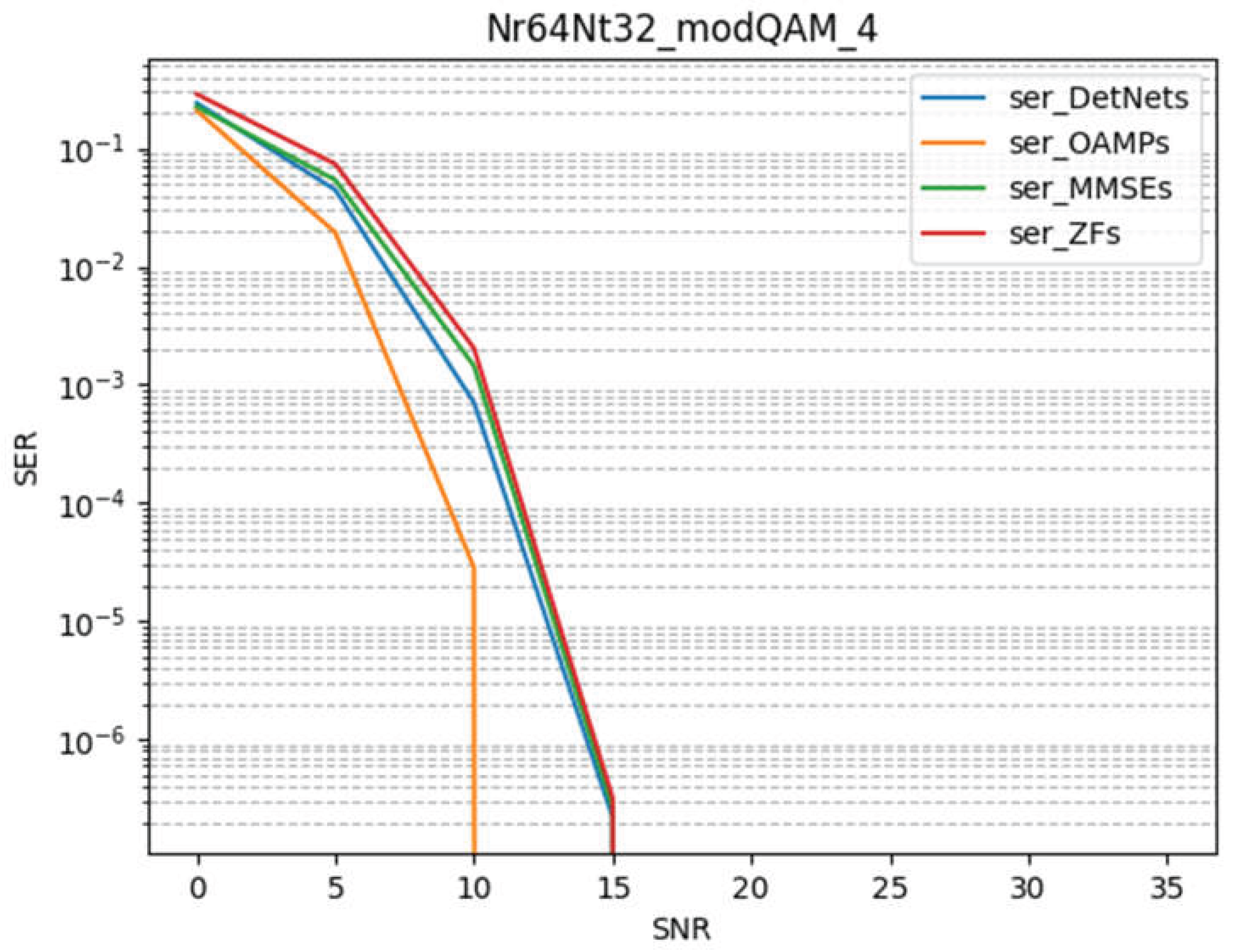
Figure 3.
The SER performance of a 30-layer DetNet without employing the simplified Hint approach.
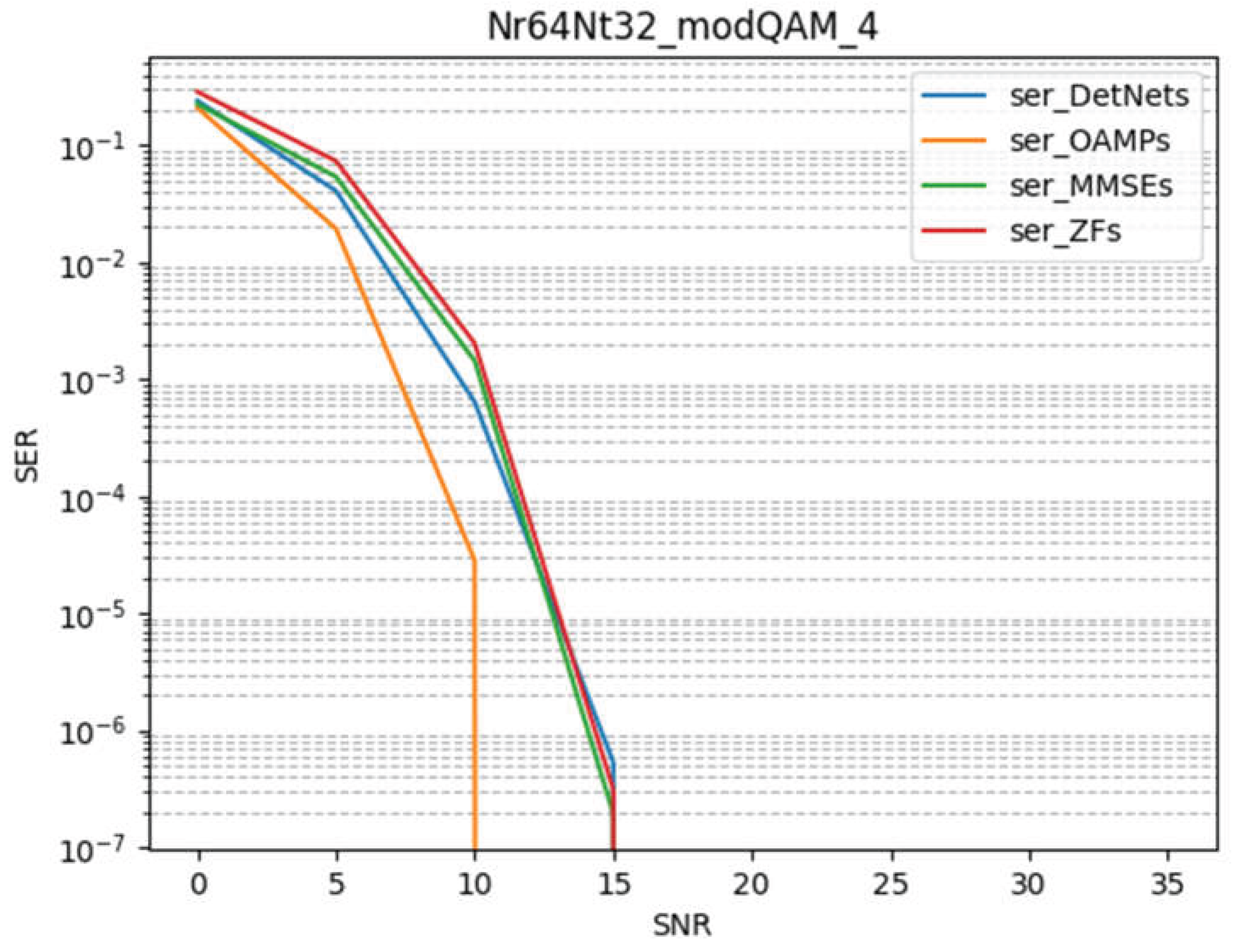
Figure 4.
The performance of a DetNet configuration limited to only 10 layers (Part 1).
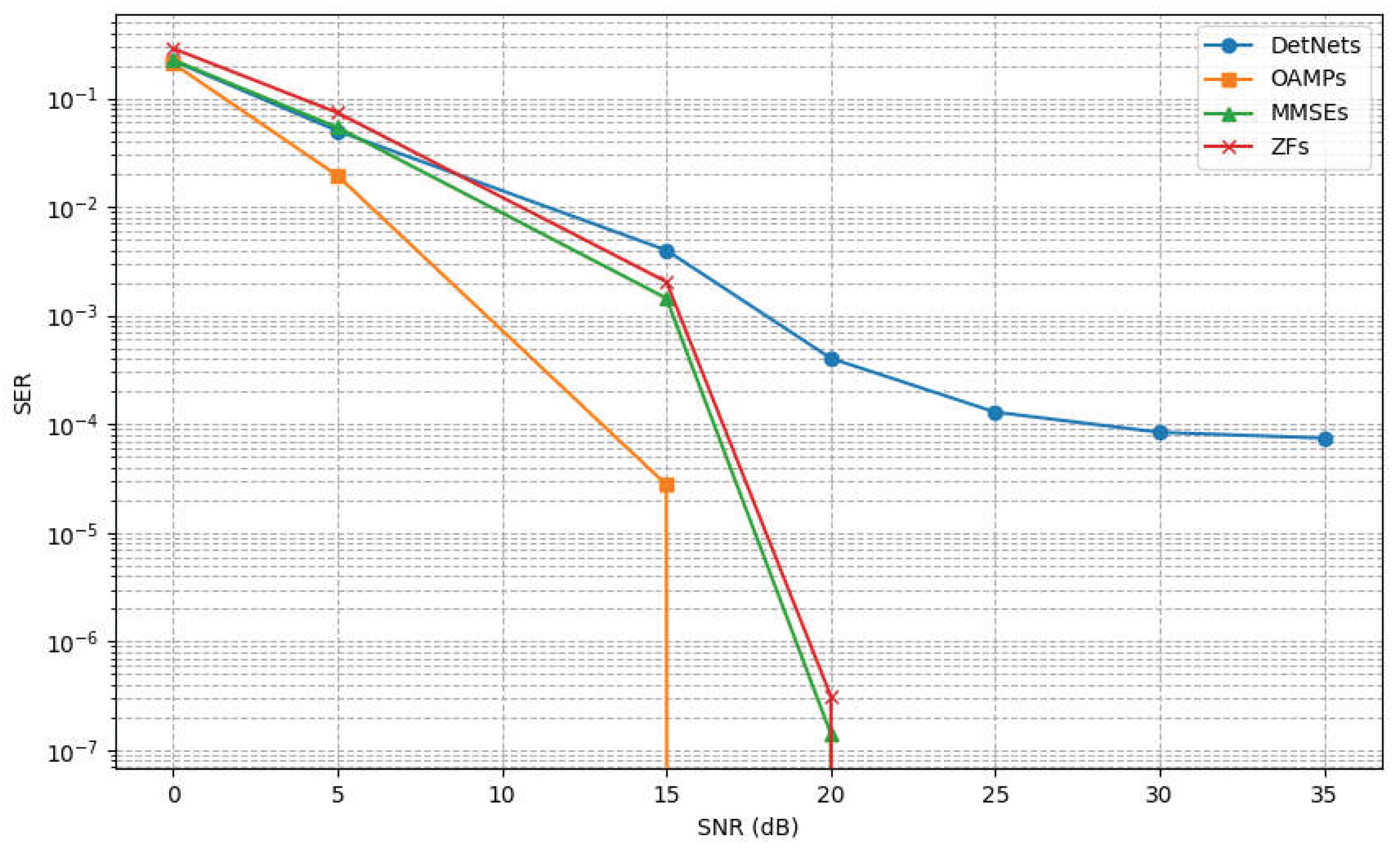
Figure 5.
The performance of a DetNet configuration limited to only 10 layers (Part 2).
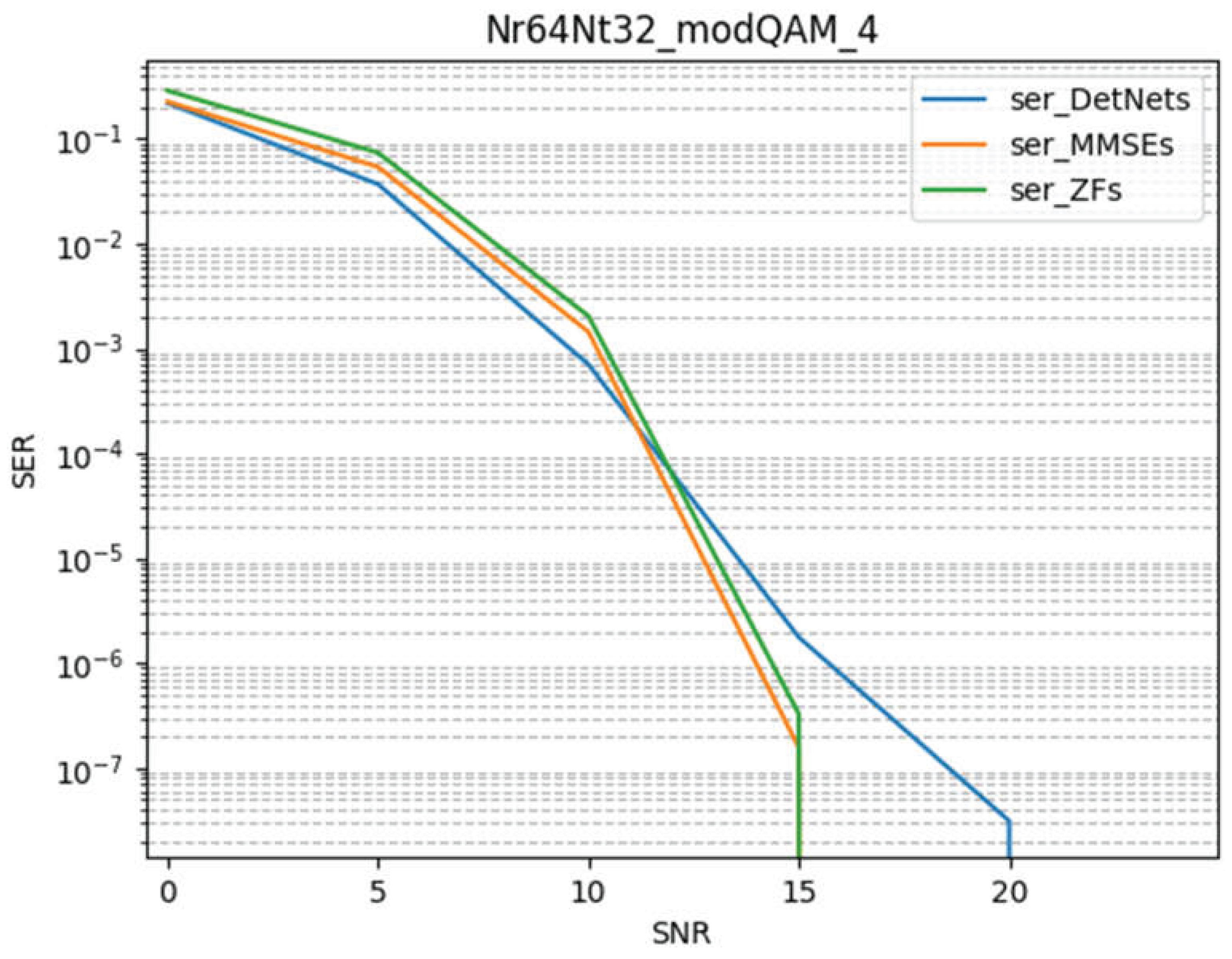
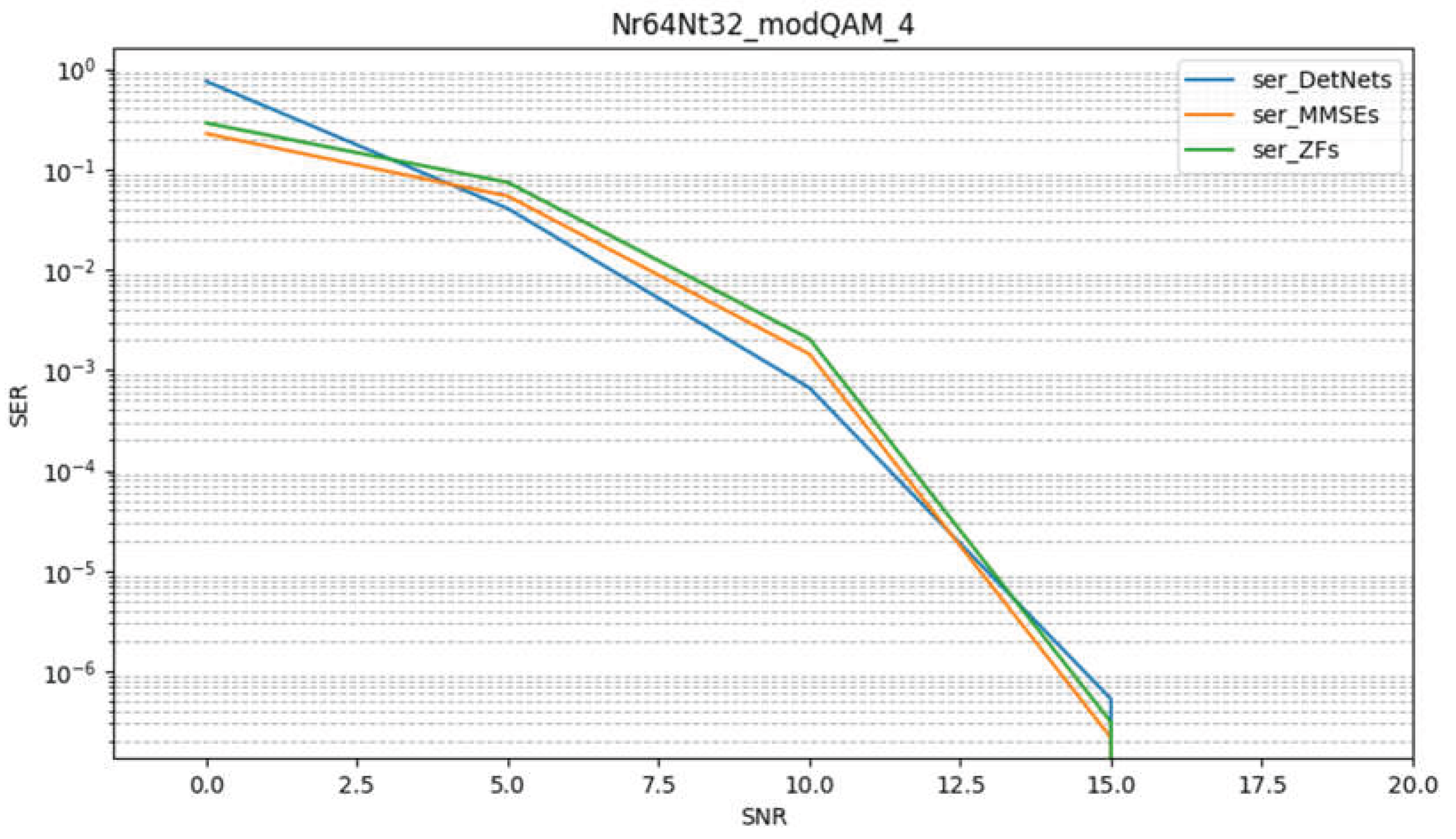
Next, we present the performance of a DetNet configuration limited to only five layers, both with and without the simplified Hint approach, as shown below. Overall, the Hint-based detection exhibits superior performance, with the only notable shortcoming occurring at 0 dB. This decline in performance could be attributed to the simplified Hint’s limited noise mitigation capacity or to unactivated channel-parameter enhancements at 0 dB. Future studies may need to incorporate special-case parameters for 0 dB conditions.
Figure 6.
The performance of a 10-layer DetNet with simplified Hint assistance (Part 1).
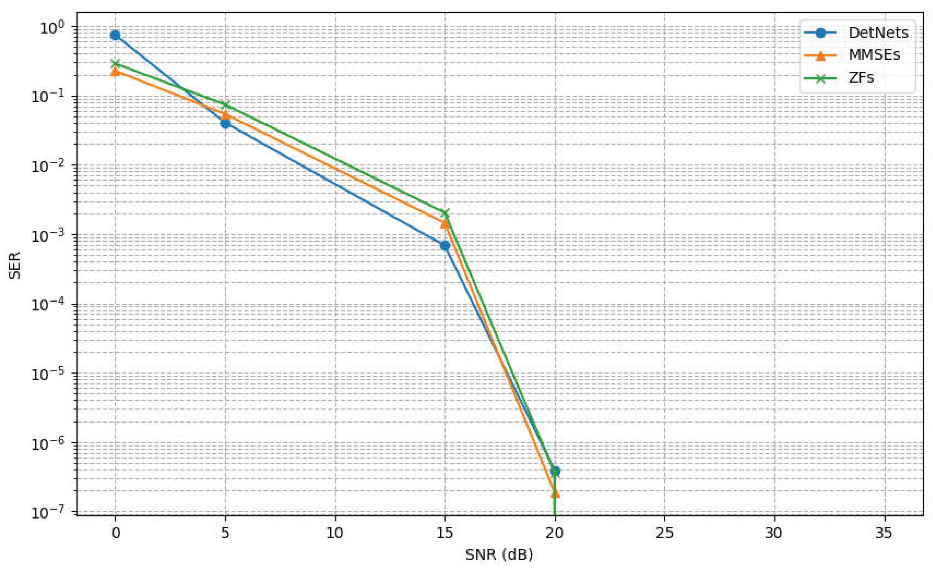
Figure 7.
The performance of a 10-layer DetNet with simplified Hint assistance (Part 2).
Under the 3GPP UMa NLOS channel conditions, the simplified Hint approach fails to provide a more effective initialization for DetNet. Without any initial assistance, DetNet achieves an SER of approximately 0.75, whereas using the simplified Hint results in an SER of around 0.2, an unacceptable outcome. This indicates a need for more refined parameter tuning and iterative strategies. According to the 3GPP model, further iterations of the NS algorithm may be required to make Hint’s performance more comparable to MMSE. Nonetheless, evaluating more accurate and complex detectors could help determine whether the simplified Hint approach can offer any performance gains in the 3GPP-Uma-NLOS environment.
Referring to OAMPNet (represented by the blue line) as a performance benchmark for other algorithms, it can be observed that, under identical configurations, OAMPNet with the assistance of the simplified Hint demonstrates greater stability and improved performance. Nevertheless, the benefits of the simplified Hint appear limited; more precise initialization vectors are needed for simpler DL-based algorithms to function effectively. In the following, we provide a brief examination of the 3GPP channel gain employed in this study, aiming to inform potential future enhancements.
Figure 8.
The performance of a five-layer DetNet without employing the simplified Hint approach.
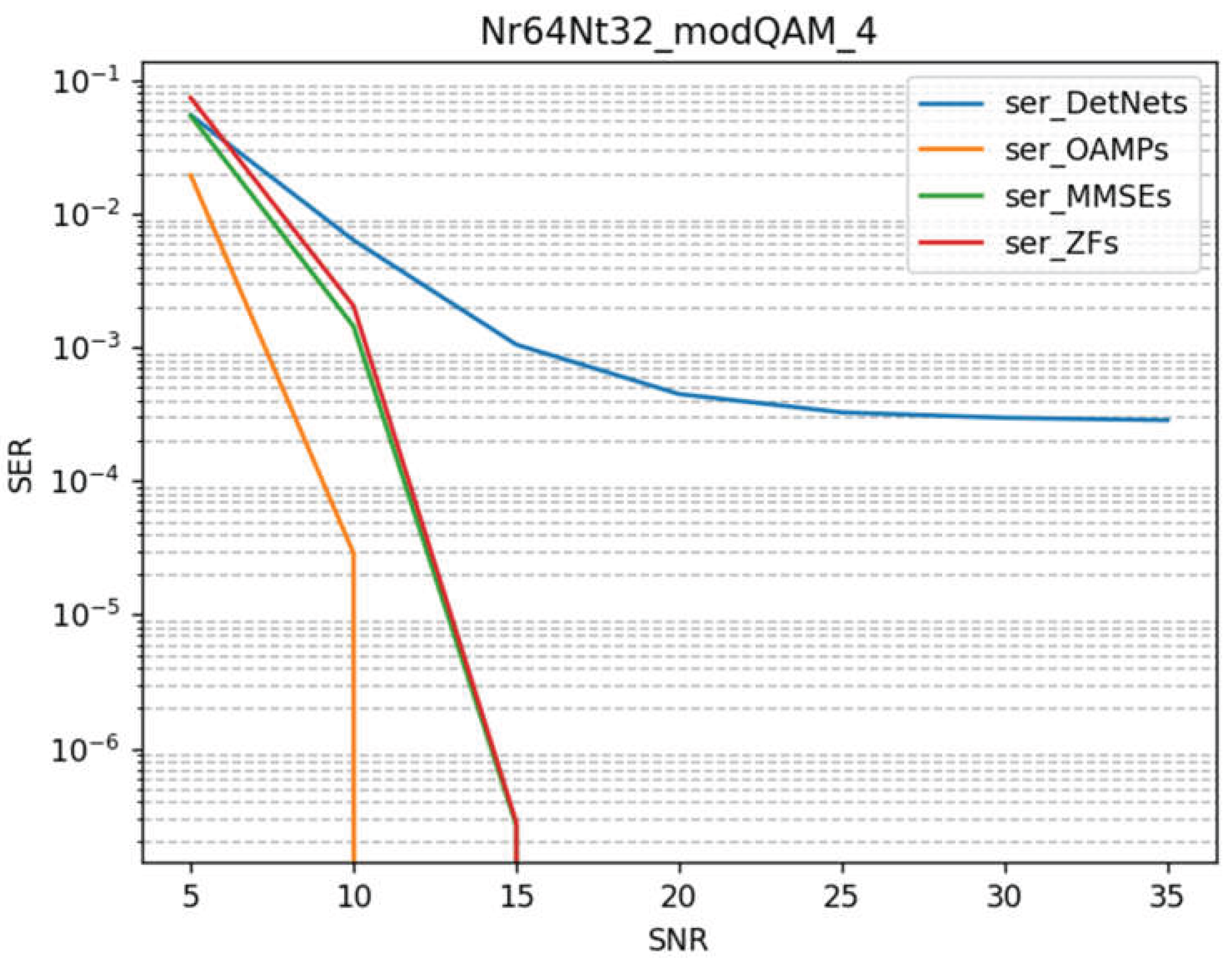
Figure 9.
The performance of a five-layer DetNet when assisted by the Hint algorithm.
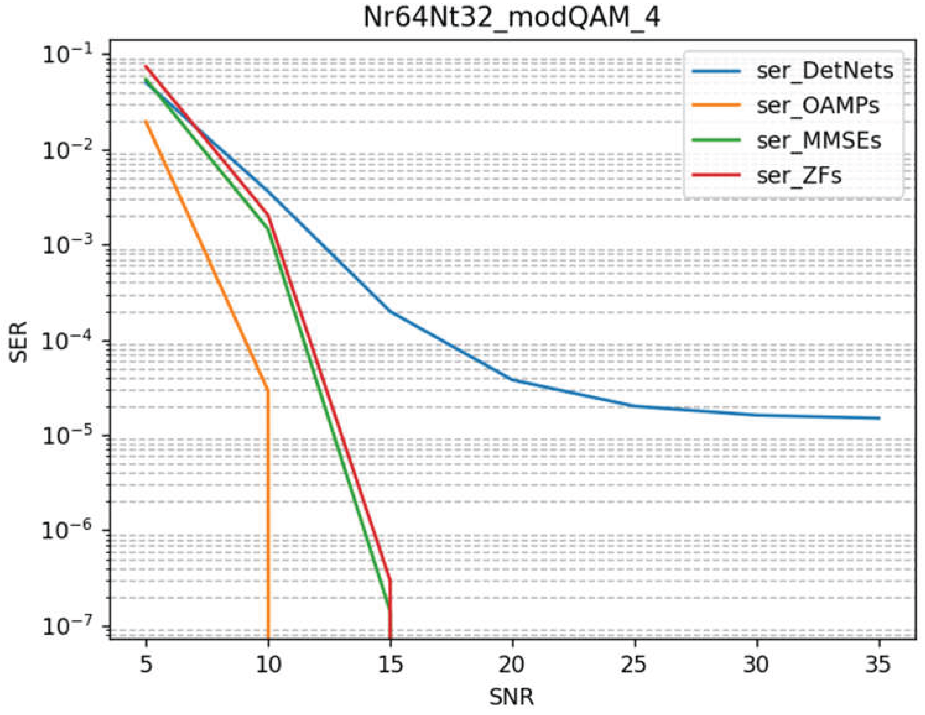
Figure 10.
The performance of a DetNet with the simplified Hint under 3GPP-Uma-NLOS conditions.
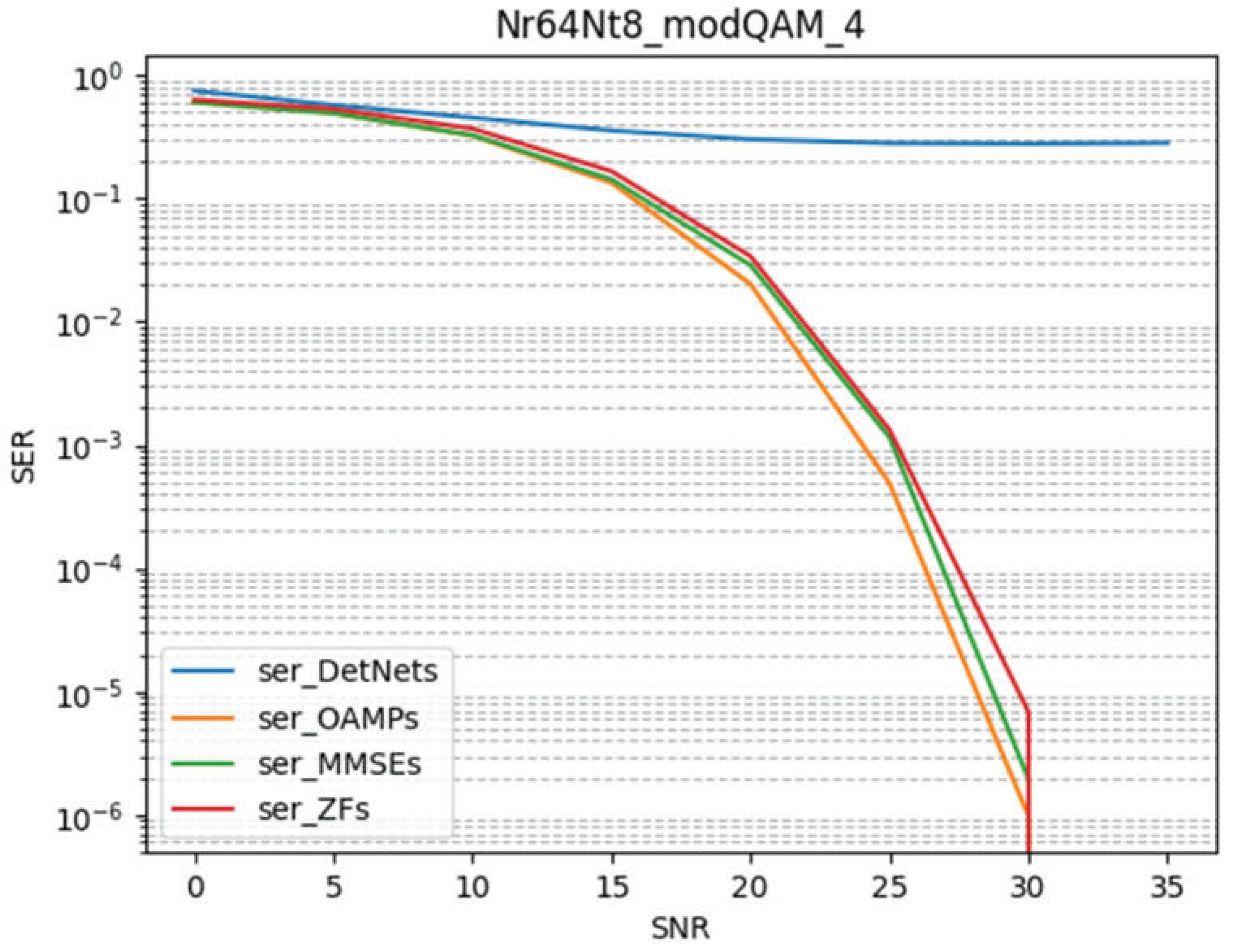
Figure 11.
The performance of OAMPNet under 3GPP-Uma-NLOS conditions.
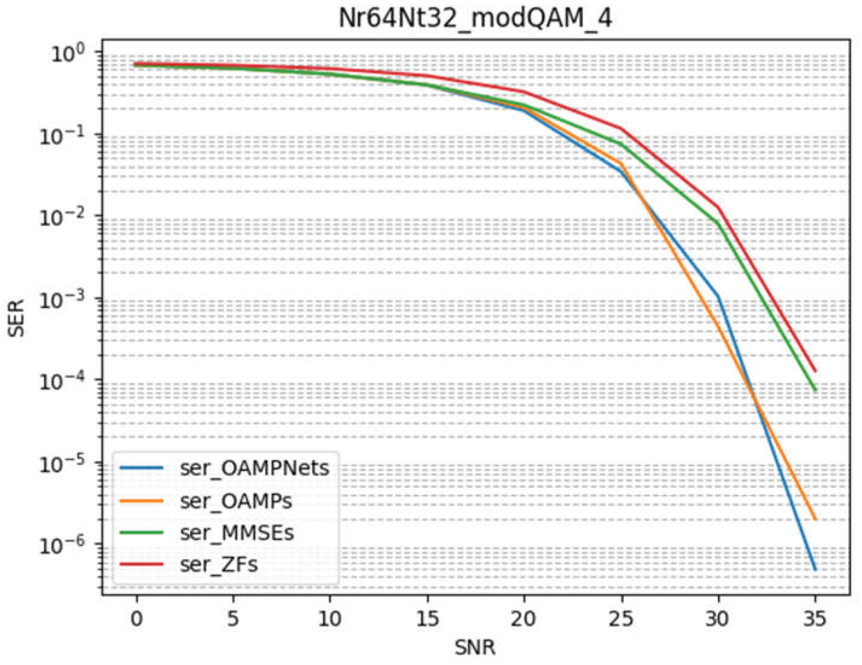
Figure 12.
The performance of OAMPNet with the simplified Hint under 3GPP-Uma-NLOS conditions.
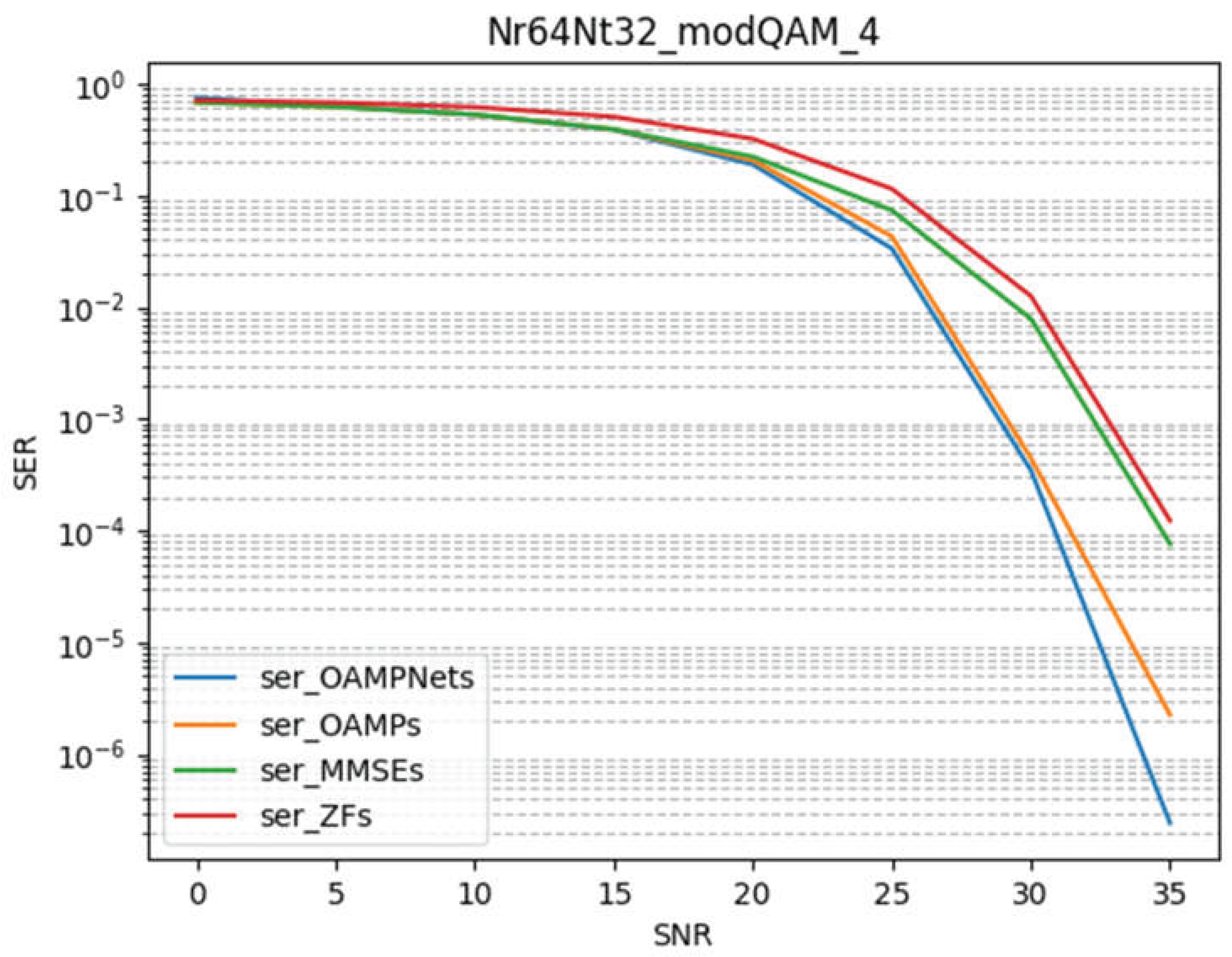
The left and right panels of Figure 13, respectively, depict the real and imaginary parts of the channel matrix. Along the x-axis are 256 subcarriers, and along the y-axis are 64 receive antennas (Nr). The color scale reflects the channel gain coefficient. In the left panel (the real part), brighter regions indicate higher gain, whereas darker regions signify lower gain. Observing these variations in channel gain helps illuminate how signal strength changes with different transmit antennas and subcarriers. In the right panel (the imaginary part), brighter and darker regions denote the magnitude and direction of phase shifts. It is apparent that the channel coefficients are extremely small, indicating severe signal attenuation in this scenario.
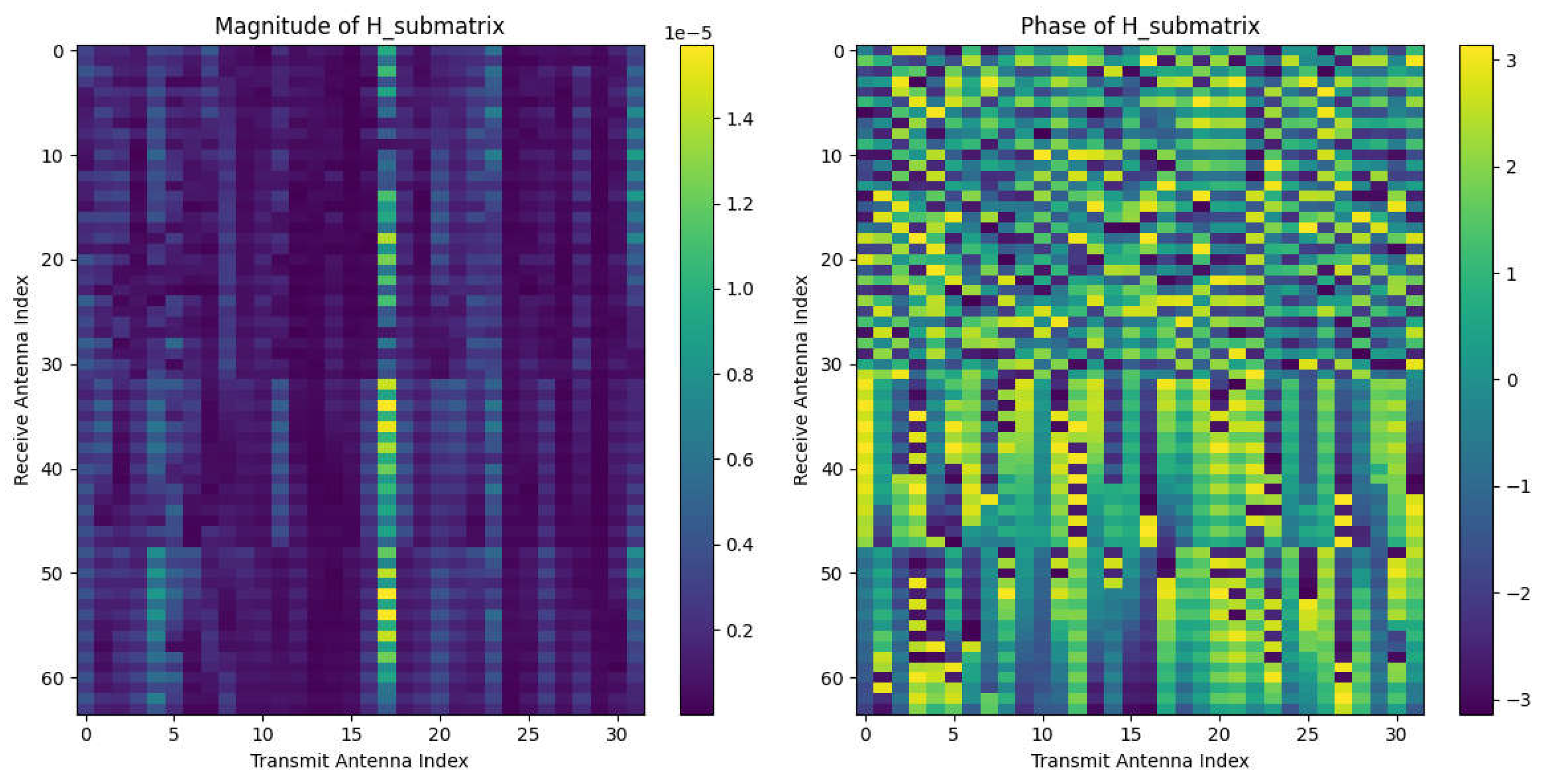
Subsequent transmitter antenna losses further corroborate this observation. Because the UMa NLOS terrain imposes a substantial path loss (in dB), judiciously increasing transmit power can facilitate more reliable signal decoding. In Figure 15 (left), the intensity data from Figure 14 are re-mapped for all receiving antennas at the BS. One particular signal channel appears notably stronger, possibly owing to a more favorable spatial position. Figure 15 (right) presents the phase image (i.e., the phase of a submatrix of H, where the color scale represents phase values ranging from −π to π. Phase fluctuations may arise from multipath effects, phase offsets, and other factors. Such a complex environment cannot be accurately modeled by a first-order Neumann series alone. Instead, one must leverage both amplitude and phase images to identify and compensate for antennas exhibiting high gain or significant phase shifts, thereby enhancing overall system performance.
Figure 14.
The average path loss across all transmit antennas.
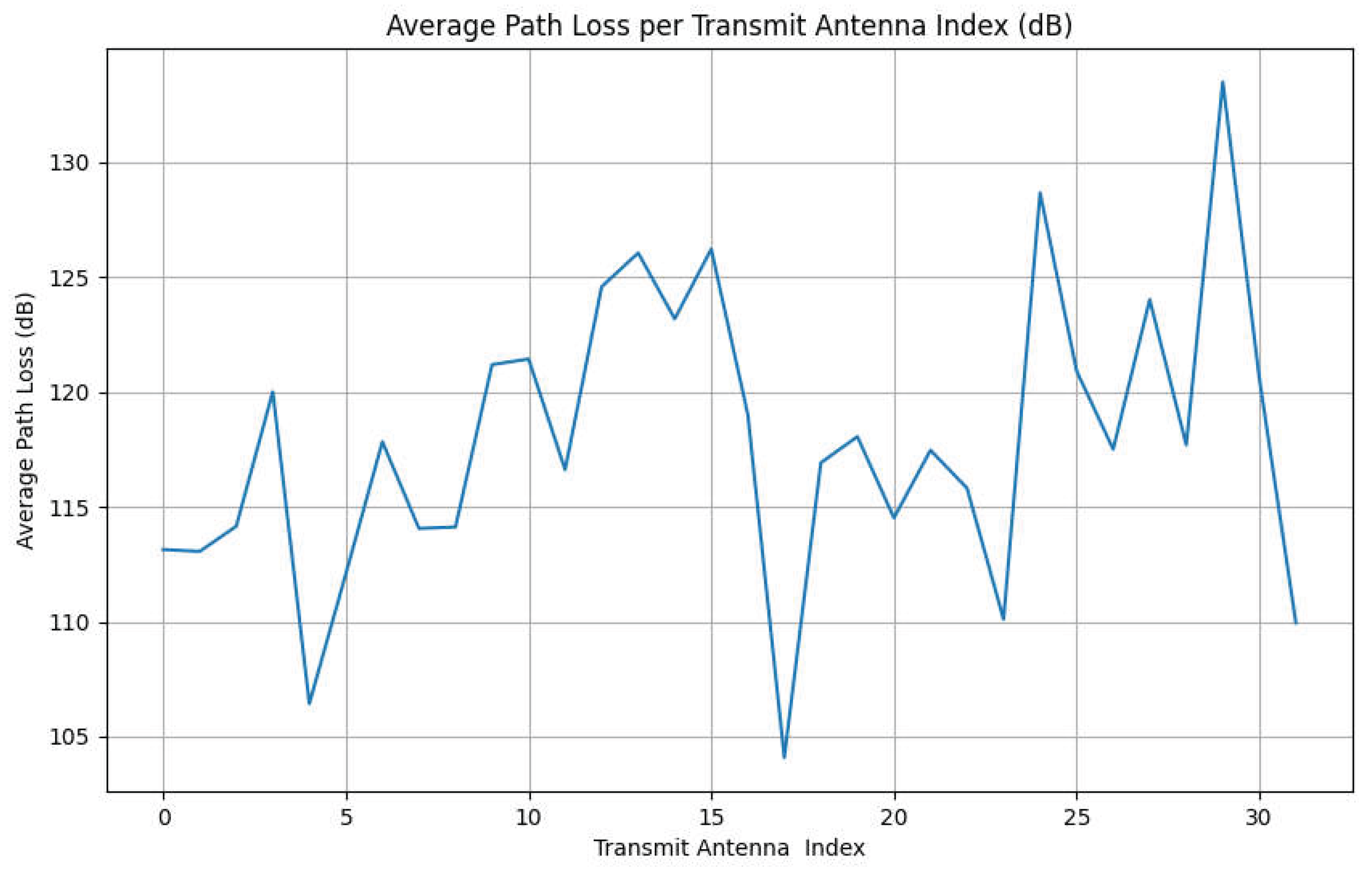
Figure 15.
The magnitude of the H submatrix and its corresponding phase distribution.
Channel equalization and precoding can be designed based on amplitude and phase information to compensate for gain and phase variations, thus improving signal quality and data throughput. As for refining the parameters within Hint, additional in-depth investigation is required. Although it remains unclear how the original Hint technique described in the literature configures its parameters, machine learning–driven iterative methods may offer a means of systematically tuning them.
Table 1 specifies N as the total number of transmit antennas across all user equipments (UEs), which is generally less than the number of antennas (K) at the base station (BS) in an mMIMO setting. L denotes the number of layers in the model. The primary advantage of the simplified Hint approach is its low complexity and the fact that it requires no training. As indicated by the table, its complexity is exceedingly low, and integrating DetNet into either the iterative process or the DNN model has a negligible impact on complexity, yet enhances computational accuracy. Nevertheless, this approach becomes insufficient when confronted with more complex environments. In such scenarios, the original method performs a two-stage Neumann series (NS) calculation to attain a more accurate Hint estimate.
For researchers seeking to delve deeper into this line of work, the optimal parameters derived from the present experiment can serve as a foundational reference. Moreover, the study that introduced MMNet also proposes training and evaluating signals using channels with prominent features, which can further improve both efficiency and performance. More in-depth investigations are needed to fully capitalize on these insights.
5. Conclusions
The primary objective of this paper is to reduce model complexity while maintaining an evaluation accuracy comparable to that of a deeper model without Hint. The results demonstrate a successful reduction in the number of model iterations while sustaining a certain level of accuracy, thereby achieving the experimental goal. Our simplified Hint retains the original method’s low complexity and avoids the additional training time required to handle environmental changes, especially under large-scale mMIMO conditions where avoiding matrix inversion significantly reduces computational burden. By serving as a low-complexity yet relatively accurate initialization algorithm, the improved Hint has the potential to foster the practical adoption of deep learning–based detection methods. Owing to various constraints, this study could not fully replicate real-world conditions. Ideally, future work will implement additional optimizations such as grid search, random search, or gradient-based optimization to further enhance parameter tuning efficiency and effectiveness. Moreover, training and evaluating signals on channels with distinct, readily identifiable features could prove crucial in strengthening the simplified Hint approach. We hope that this method will eventually be tested and refined in the context of 6G, Wi-Fi 7, or future communication protocols.
References
- Jiang, W.; Han, B.; Habibi, M. A.; Schotten, H. D. The Road Towards 6G: A Comprehensive Survey. IEEE Open J. Commun. Soc. 2021, vol. 2, 334–366. [Google Scholar] [CrossRef]
- Jundhare, M. D.; Kulkarni, A. V. An overview and current development of femtocells in 5G technology. 2016 IEEE International Conference on Advances in Electronics, Communication and Computer Technology (ICAECCT), Pune, India, 2016; pp. 204–209. [Google Scholar]
- Albreem, M. A.; Juntti, M.; Shahabuddin, S. Massive MIMO Detection Techniques: A Survey. IEEE Commun. Surv. Tutor. 2019, vol. 21(no. 4), 3109–3132. [Google Scholar] [CrossRef]
- Lu, L.; Li, G. Y.; Swindlehurst, A. L.; Ashikhmin, A.; Zhang, R. An Overview of Massive MIMO: Benefits and Challenges. IEEE J. Sel. Top. Signal Process. 2014, vol. 8(no. 5), 742–758. [Google Scholar] [CrossRef]
- Larsson, E. G.; Edfors, O.; Tufvesson, F.; Marzetta, T. L. Massive MIMO for next generation wireless systems. IEEE Commun. Mag. 2014, vol. 52(no. 2), 186–195. [Google Scholar] [CrossRef]
- Larsson, E. G. MIMO Detection Methods: How They Work. IEEE Signal Process. Mag. 2009, vol. 26(no. 3), 91–95. [Google Scholar] [CrossRef]
- Elijah; Abdul Rahim, S. K.; New, W. K.; Leow, C. Y.; Cumanan, K.; Geok, T. Kim. Intelligent Massive MIMO Systems for Beyond 5G Networks: An Overview and Future Trends. IEEE Access 2022, vol. 10, 102532–102563. [Google Scholar] [CrossRef]
- Samuel, N.; Diskin, T.; Wiesel, A. Deep MIMO detection. 2017 IEEE 18th International Workshop on Signal Processing Advances in Wireless Communications (SPAWC), Sapporo, Japan, 2017; pp. 1–5. [Google Scholar]
- Samuel, N.; Diskin, T.; Wiesel, A. Learning to Detect. IEEE Trans. Signal Process. 2019, vol. 67(no. 10), 2554–2564. [Google Scholar] [CrossRef]
- He, H.; Wen, C. -K.; Jin, S.; Li, G. Y. A Model-Driven Deep Learning Network for MIMO Detection. 2018 IEEE Global Conference on Signal and Information Processing (GlobalSIP), Anaheim, CA, USA, 2018; pp. 584–588. [Google Scholar]
- Khani, M.; Alizadeh, M.; Hoydis, J.; Fleming, P. Adaptive Neural Signal Detection for Massive MIMO. IEEE Trans. Wirel. Commun. 2020, vol. 19(no. 8), 5635–5648. [Google Scholar] [CrossRef]
- Dai, L.; Gao, X.; Su, X.; Han, S.; I, C. -L.; Wang, Z. Low-Complexity Soft-Output Signal Detection Based on Gauss–Seidel Method for Uplink Multiuser Large-Scale MIMO Systems. IEEE Trans. Veh. Technol. 2015, vol. 64(no. 10), 4839–4845. [Google Scholar] [CrossRef]
- Wu, Z.; Zhang, C.; Xue, Y.; Xu, S.; You, X. Efficient architecture for soft-output massive MIMO detection with Gauss-Seidel method. 2016 IEEE International Symposium on Circuits and Systems (ISCAS), Montreal, QC, Canada, 2016; pp. 1886–1889. [Google Scholar]
- Gao, X.; Lu, Z.; Han, Y.; Ning, J. Near-optimal signal detection with low complexity based on Gauss-Seidel method for uplink large-scale MIMO systems. 2014 IEEE International Symposium on Broadband Multimedia Systems and Broadcasting, Beijing, China, 2014; pp. 1–4. [Google Scholar]
- Rezvani, M.; Adve, R.; bin Sediq, A.; El-Keyi, A. Hint: a Clue as to Where to Start an Iterative Massive MIMO Detection Process. ICC 2023 - IEEE International Conference on Communications, Rome, Italy, 2023; pp. 1376–1381. [Google Scholar]
- Mondal, B.; et al. 3D channel model in 3GPP. IEEE Commun. Mag. 2015, vol. 53(no. 3), 16–23. [Google Scholar] [CrossRef]
- Rumney, M.; Kyösti, P.; Hentilä, L. 3GPP channel model developments for 5G NR requirements and testing. 12th European Conference on Antennas and Propagation (EuCAP 2018), London, UK, 2018; pp. 1–5. [Google Scholar]
- Bakulin, M. G.; Kreindelin, V. B.; Pankratov, D. Y.; Stepanova, A. G. Modified Newton’s Method in Massive MIMO Demodulation with non-Gaussian Approximation. In 2022 Systems of Signals Generating and Processing in the Field of on Board Communications; Moscow, Russian Federation, 2022; pp. 1–5. [Google Scholar]
- Studer, C.; Fateh, S.; Seethaler, D. ASIC Implementation of Soft-Input Soft-Output MIMO Detection Using MMSE Parallel Interference Cancellation. IEEE J. Solid-State Circuits 2011, vol. 46(no. 7), 1754–1765. [Google Scholar] [CrossRef]
- Gerstacker, W. H.; Schober, R. Equalization concepts for EDGE. IEEE Trans. Wirel. Commun. 2002, vol. 1(no. 1), 190–199. [Google Scholar] [CrossRef]
- Jaeckel, Stephan; Raschkowski, Leszek; Thiele, Lars. Document from Quasi Deterministic Radio Channel Generator User Manual and Documentation Revision: v2.8.1. 2023. [Google Scholar] [CrossRef] [PubMed]
- Kosmanos, D.; Chaikalis, C.; Savvas, I.K. 3GPP 5G V2X Scenarios: Performance of QoS Parameters Using Turbo Codes; Telecom, 2022; Volume 3, pp. 174–194. [Google Scholar]
- ZOMEV. Deep Neural Network (DNN) Explained. 15 Apr 2024. Available online: https://medium.com/@zomev/deep-neural-network-dnn-explained-0f7311a0e869.
Figure 1.
The reconstruction effect of the Hint algorithm.
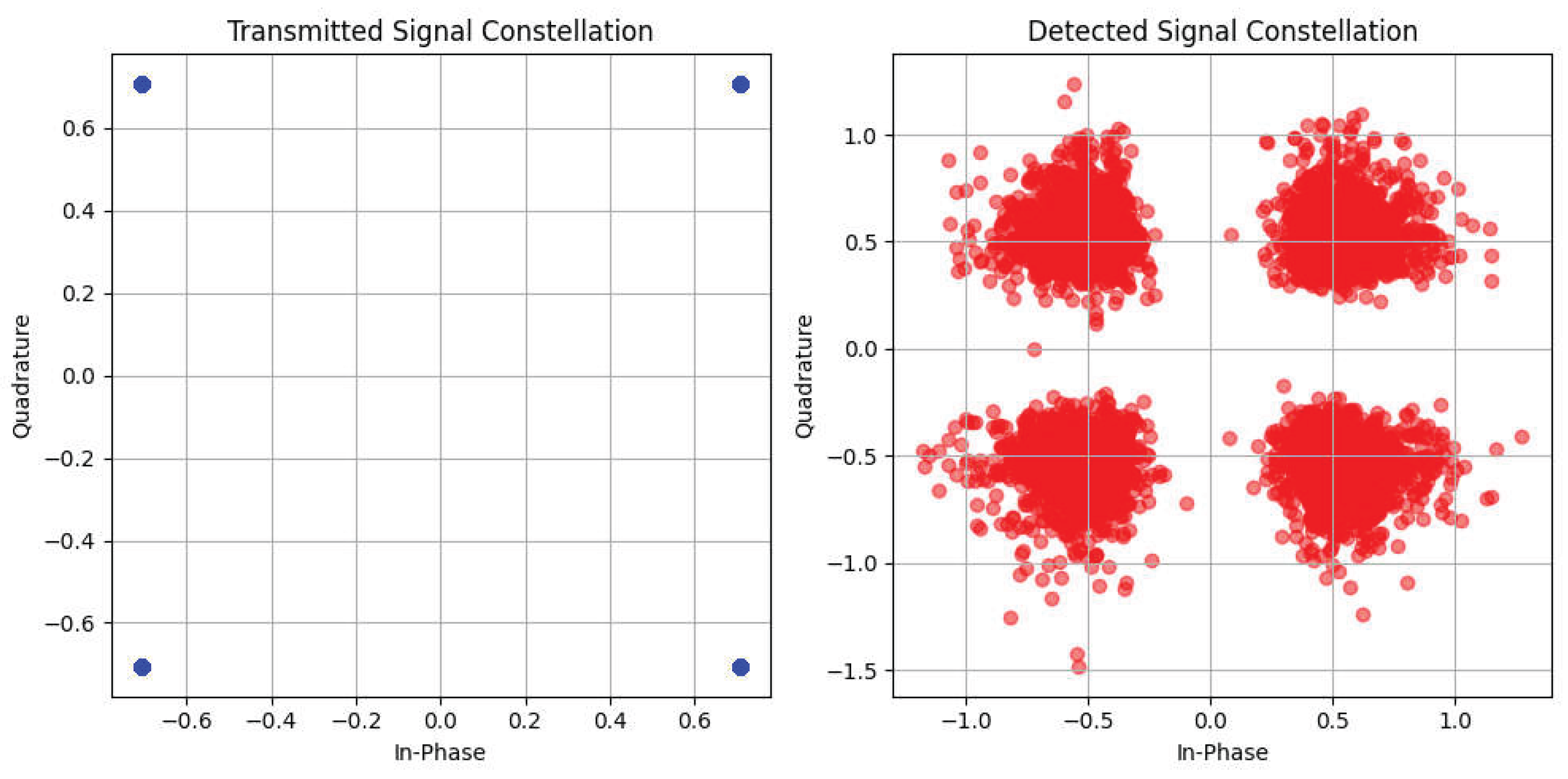
Figure 13.
A segment of the 3GPP UMa NLOS channel data under conditions of Nr=64 and Nt=32.
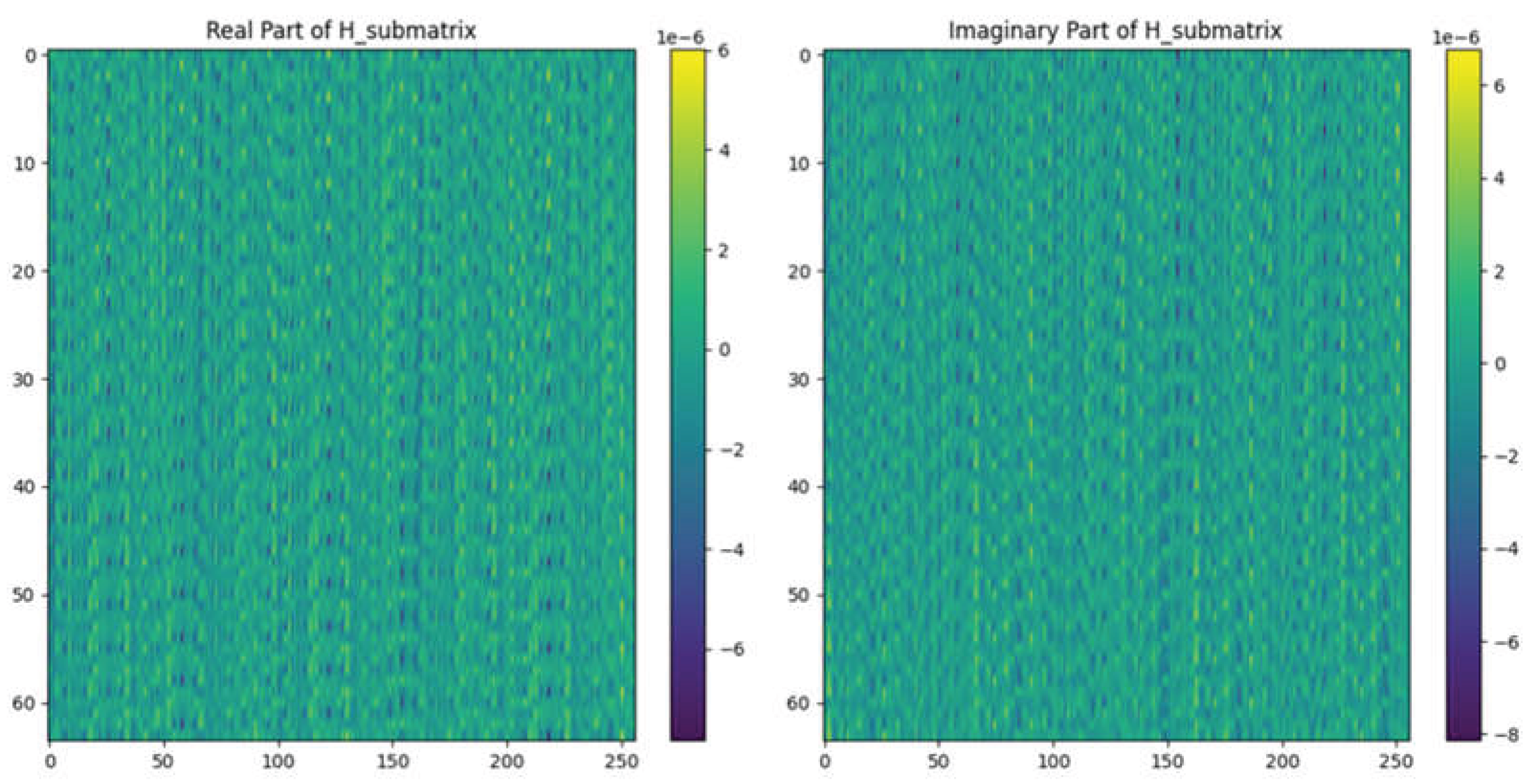

Table 1.
Computational complexity of algorithms evaluated in this experiment, where N denotes the number of transmit antennas.
Disclaimer/Publisher’s Note: The statements, opinions and data contained in all publications are solely those of the individual author(s) and contributor(s) and not of MDPI and/or the editor(s). MDPI and/or the editor(s) disclaim responsibility for any injury to people or property resulting from any ideas, methods, instructions or products referred to in the content. |
© 2026 by the authors. Licensee MDPI, Basel, Switzerland. This article is an open access article distributed under the terms and conditions of the Creative Commons Attribution (CC BY) license (http://creativecommons.org/licenses/by/4.0/).
Copyright: This open access article is published under a Creative Commons CC BY 4.0 license, which permit the free download, distribution, and reuse, provided that the author and preprint are cited in any reuse.


