

Submitted:
07 July 2026
Posted:
08 July 2026
You are already at the latest version
Abstract
The low speed diesel engines are the most widespread in marine power plants. Their fuel efficiency falls with growing intake and charge air temperatures. Therefore, cyclic air cooling ensures a sustainable performance of ship engines along the voyage with high fuel efficiency. The absorption chillers of lithium-bromide type (LBCh) are the most widened due to their high efficiency with COP of about 0.7. However, they are complicated and need a special room. The ejector chillers (ECh) consist mostly of heat exchangers which might be placed on the board side and transverse bulkheads in engine room, but their efficiency is considerably less than that of LBCh: COP = 0.2–0.3 depending on the temperatures of heat source, boiling and condensing refrigerant. The cogeneration engines are desired to produce hot water with temperature of about 90 °C. If hot water is applied as a heat source their COP is about 0.2, that inevitable leads to reduced refrigeration capacity and undercooling engine cyclic air. The lack of ECh cooling capacity has been boosted by the heat left from unloaded LBCh. Basing on a such general approach the overall thermal load on air cooling system has been distributed between LBCh and ECh to minimize LBCh sizes. A concept of ship cogeneration engine air cooling by combine LBCh and ECh has been realized by corresponding cooling system scheme solution. The general statements and assumptions of proposed design methodology of combine air cooling systems for diesel engines are introduced.
Keywords:
ship
; diesel engine
; voyage
; fuel consumption
; cooling air
; thermal load
; chiller
1. Introduction
The fuel and thermodynamic efficiency as the whole of combustion engines of any type (internal combustion engines (ICE) [1,2], gas engines (GE) [3,4] and turbines (GT) [5,6]) depends on the temperature of their cyclic air and falls with its growing [7,8]. Therefore, the rise of combustion engine efficiency at raised air temperatures through air cooling is the general trend in ICE [7,8], GE [9,10], GT [11,12] and energetics as the whole.
The absorption chillers of lithium-bromide (LBCh) [13,14], ammonia-water [15,16] and ejector (ECh) [17,18] types transforming exhaust heat of the engines are usually applied for this purpose as well as jet thermopressors using refrigerant [19,20] or water [21,22] as working fluids. The combustion engines are often applied as driving engines in power plants for combined energy generation: mechanical or electrical power and heat (cogeneration) [23,24] and refrigeration (trigeneration) [25,26] in stationary [27,28] and marine [29,30] applications. Therefore, the engine cyclic air cooling enables to enhance the efficiency of cogeneration [31,32] and trigeneration [33,34] plants as the whole.
The performance of ship diesel engines is characterized by considerable changes in the temperatures of ambient air and sea water along the voyage and the temperatures of intake and charge air accordingly [35,36]. In the case of ship power plants of cogeneration type the exhaust heat is used for production of hot water of about 90 °C [37,38], which heat potential is less than steam from exhaust steam boiler [39,40]. A lowered potential of heat source [41,42] requires application of combined chillers [43,44] and rational heat distribution between them [45,46]. The absorption chillers of lithium-bromide type (LBCh) of a simple cycle are the most widened due to their high efficiency estimated by coefficient of performance COP from 0.7 to 0.8 [47,48]. However, they are complicated and need a special room. The ejector chillers (ECh) [49,50] consist mostly of heat exchangers [51,52] which might be placed on the board side and transverse bulkheads in engine room, but their efficiency is considerably less than that of LBCh: COP = 0.2–0.3 depending on the temperatures of heat source, boiling and condensing [53,54] refrigerants. If hot water (about 90 °C) is applied as a heat source their COP is about 0.2, that inevitable leads to reduced refrigeration capacity and undercooling engine cyclic air.
It is quite logical to compensate the lack of ECh refrigeration capacity by the exceedant capacity of LBCh through redistributing the engine exhaust heat between LBCh and ECh to reduce the sizes of LBCh and provide deep cooling inlet and charge air simultaneously. Certainly, such heat recuperation requires the application of the heat exchanges [55,56] ensuring intensive evaporation [57,58] in cooling and condensing circuits [59,60] to provide the minimum temperature differences leading to lowered cooled air temperatures and increased magnitude of the available exhaust heat.
Deep utilization of the exhaust gas heat in boilers [61,62] enables to increase the available heat [63,64] for covering its lack. The application of exhaust boilers with low temperature condensing surfaces [65,66] are especially effective when combusting water fuel emulsion instead of heavy diesel fuel [67,68]. The latter assists to reduce the sulfurous fuel consumption and harmful emissions into environment as result [69,70] as well as application of other kinds of fuels.
Some methodological approaches to define design loads on ambient air cooling and air conditioning systems [71,72] as standing along [73,74] and the subsystems of combined cooling, heat and power (CCHP) plants [75,76] desired for space [77,78] and engine cyclic air [79,80] cooling are developed. They are focused to match current cooling duties in response to on site [81,82] or along route lines [83,84] and ship voyages [85,86] varying climatic conditions without oversizing.
Issuing from the problem of placing the complicated LBCh unit in chip engine room, the overall thermal load on air cooling system is to be distributed between LBCh and ECh to minimize LBCh sizes and provide deep cooling inlet and charge air simultaneously. The such concept of ship cogeneration engine air cooling by aggregate system with LBCh and ECh [87,88] might be considered as the further development of the general trend of the engine cyclic air cooling by combined chillers [89,90] in ICE, GE and GT [91,92], as well as based on them integrated energy plants for combined power, heat and refrigeration generation [93,94] in aspect of the problematic placing machinery equipment aboard ship [95,96]
The aim of the work is to develop a concept of combine engine cyclic air cooling in LBCh and ECh, accompanied by corresponding system solution based on a general approach to minimize LBCh sizes through overall thermal load distribution between LBCh and ECh, enabling easy mounting the chillers in engine room and cooling engine inlet and charge air.
Basing on a such general approach the overall thermal load on air cooling system has been distributed between LBCh and ECh to minimize LBCh sizes and provide cooling inlet and charge air to the target temperatures simultaneously.
2. Materials and Methods
The following assumptions were accepted while choosing the target values of the temperatures of air at the engine inlet tin = 15°C cooled by LBCh and charge air tch = 22°C cooled by ECh: tin = tcw +8= 15°C, where tcw = 7°C – chilled water from LBCh, 8°C – temperature difference in air cooler at the engine inlet between cooled air and chilled water from LBCh; tch = t0 +5+12= 22°C, where t0 = 5°C – refrigerant boiling temperature in refrigerant evaporator-air cooler of ECh, 5°C – temperature difference in refrigerant evaporator-water cooler between intermediate cooled water and boiling refrigerant, 12°C – temperature difference in low temperature charge air cooler between cooled charge air and intermediate cooled water.
So as the COP of ECh is very sensitive to variation of thermal loads it is desired for cooling the charge air, previously precooled by sea water, which is characterized by less fluctuation of thermal loads compared to the sucked ambient air.
The analyses of the available heat of engine high temperature charge air at the outlet of turbocharger and exhaust gas to be converted to refrigeration by the waste heat recovery chillers for cooling turbocharger inlet air and subcooling charge air, previously precooled by sea water, has been performed according to the next steps.
Firstly, the overall summarized available heat Qexh+ch of engine exhaust gas Qexh and high temperature charge air Qch , converted into refrigeration by LBCh Q0.exh+chLB(0.7) with COP=0.7 and by ECh Q0.exh+chE(0.2) with COP=0.2 separately, have been compared with summarized heat needs for cooling engine inlet air to 15°C and charge air to 22°C separately by LBCh Qh15+22BL(0.7) and ECh Qh15+22E(0.2) for comparing analysis of the excess of heat Qh15+22LB(0.7)ex for LBCh and the lack (deficit) of heat Qh15+22E(0.2)d for ECh.
Thus, the first step of the analyses has been focused to reveal generally the reserves of available heat left from LBCh Q0.exh+chLB(0.7)ex for boosting a charge air heat to reduce its deficit for ECh Q0.exh+chE(0.2)d.
The exhaust heat exceedances QexhLBex15 left from LBCh cooling intake air to 15 °C is used as a boost additional heat being converted by ECh with COP=0.2 for cooling charge air in addition to the heat of charge air Qch as their sum Qch+LB = Qch +QexhLBex15 .
The fuel saving ∑B of engine over the ship voyage is defined by summation as:
where: Δta = ta.in –ta2 ;∙ ta.in and ta2 – temperatures of air at the inlet and outlet of cooler; be –specific fuel consumption per 1 kW of engine power, g/kWh; Δbe /Δta – specific fuel decrease for 1°C reduction in air temperature; Pe – power of ship engine, kW; τ – time of operation at definite reduction in air temperature Δta .
∑B = ∑(ta.in – ta2 )τ (Δbe /Δta ) Pe,
A ship main diesel engine 6S60MC6.1-TI is applied as example [2]: service power Pe = 10 MW; air mass flow rate Ga = 24 kg/s.
A cooling capacity Q0 needed for cooling air by temperature drop Δta is calculated as
where ξ – specific heat ratio calculated as the total heat, rejected from air (sensible and latent), related to sensible heat; сa – specific heat of wet air, kJ/(kg·K).
Q0 = сa ξ∙Δta ∙Ga,
The temperature of ship engine intake air sucked from engine room is defined as ta.in = tamb + 10 ºС.
The real cooling capacities Q0 of LBCh and ECh depends on the available exhaust gas and charge air heat Qh and COP:
with COP=0.7 for LBCh [47,48] and COP=0.2 for ECh [53,54].
Q0 = COP Qch
The coefficient of performance COP is evaluated as the ratio of cooling capacity Q0 produced to the heat Qh required: COP= Q0/Qh .
The actual fuel decrease when cooling sucked air:
B = Δta (Δbe /Δta )∙Pe.
The current magnitudes of reduction in specific fuel consumption Δbe due to drops in engine air temperature Δta during the ship voyage were determined by software package "mandieselturbo" and "ceas".[97].
The increase in specific fuel consumption Δbe with increasing air temperature at the inlet to turbochargr and cooling supercharge air water by 10 ° C is evaluated according to the Table 1 [29,97]. According to [29,30] the increase in temperature of charge air is taken equal to the increase in temperature of cooling water.
The results of comparing the heat needed for cooling engine cyclic air during the voyage with its available magnitude (heat of exhaust gas and charge air) enables to reveal the exceedances or deficit of the available waste heat and, hence, the reserves for cooling intake or charge air through using the waste heat exceedances and further redistribution of the heat between LBCh and ECh involving the recuperation of current heat exceedances to cover peak needs.
Therefore, firstly, the cooling capacities required for cooperative cooling intake and charge air and corresponding waste heat needs were compared to the available heat of exhaust gas and charge air for cooling air separately in ECh and LBCh). Afterwards additional thermal potential reserves for charge and intake air cooling were defined in response to (accordingly) the exceeding waste heat.
Schemes of a typical exhaust heat recovery system of a cogeneration marine low-speed diesel engine (DE) desired to produce a hot water with temperature of about 90 °С to cover ship heating needs and the exhaust boiler feed water heated by a high potential heat of charge air and developed version for cooling intake and charge air are shown in Figure 1.
The intake and charge air cooling efficiency was evaluated for marine diesel engine 6S60MC6.1-TI of low-speed type with service power Pe = 10 MW at the 90 % load and climatic parameters according to ISO, specific fuel consumption bе = 170 g/(kWh) and intake air mass flow rate 24 kg/s. For the analysis of the cooling system thermal loading and engine fuel reduction in response to the air temperature drop under ambient air and sea water temperatures changes during voyage the program "mandieselturbo" was applied [35,36].
So, the calculation results of the output gained due to cooling diesel engine cyclic air (based on "mandieselturbo") approved that each 10 °C drop in inlet air leads to decrease in specific fuel consumption by 1.2 g/(kWh) and in the case of charge air cooling – by about 1.1 g/(kWh).
The actual thermal loads for cooling engine cyclic air, the available heat of exhaust gas and charge air and its distribution between LBCh and ECh for cooling intake and charge air are evaluated for climatic conditions changing during voyage Odesa-Yokogama as example. The variations in ambient air and sea water parameters along the target voyage are shown in Figure 2.
The parameters of climatic conditions (seawater temperature tsw [19], relative humidity φa and ambient air temperature ta) during the voyage [20] are picked in Figure 2.
When climatic conditions change during the trade voyage, the heat load on the cooling system, id est. required cooling capacity Q0 , as well as the corresponding heat consumption Qh of waste heat recovery chillers, Qh = Q0 /COP, changes too.
The following characteristics of the ECh are chosen: refrigerant R142b boiling temperature in the evaporator-air cooler t0 = 5 oС and in the generator tg = 90 oС.
3. Results
The calculation results of available exhaust gas Qexh and charge air Qch heat and their summation Qexh+ch , as well as the excesses Qh15+22LB(0.7)ex of the sum exhaust gas and charge air heat Qexh+ch over the heat needs for cooling inlet air to 15 °С and charge air to 22 °С by LBCh (COP = 0.7) and the heat deficit Qh15+22E(0.2)d for ECh (COP = 0.2) during the target voyage are presented in Figure 3.
As Figure 3 shows, the magnitudes of the overall heat excesses Qh15+22LB(0.7)ex over the heat needs for cooling inlet air to 15 °С and charge air to 22 °С by LBCh (COP= 0.7) are nearly half the available sum heat Qexh+ch . Such large excesses Qh15+22LB(0.7)ex of the sum heat for LBCh (COP = 0.7), which are even higher the heat deficit Qh15+22E(0.2)d for ECh (COP = 0.2), evidences the heat reserves to reduce the heat deficit Qh15+22(0.2)d for ECh.
The heat excesses Qexh+chBL(0.7)ex = Qexh+ch – Qh15+22BL(0.7) , from where heat needs Qh15+22BL(0.7) = Qexh+ch – Qexh+chBL(0.7)ex .
The rational redistribution of the heat (exhaust gas and charge air heat) between LBCh and ECh, as well as corresponding cooling capacities for cooling engine inlet and charge air makes it possible to reduce the sizes of LBCh limited by cooling capacities Q0.15 needed for cooling intake air to 15 °С.
The calculation results on the exceedances QexhLBex15 of the exhaust heat Qexh over the required heat Qh15LB for intake air cooling to 15 °С by ACh (COP=0.7) are depicted in Figure 4.
The heat needed for LBCh to cool intake air to 15 °С is defined as Qh15LB = Q0.15 /0.7, as well as cooling capacities Q0.exhLB available for LBCh with COP=0.7 issuing from the heat of exhaust gas Qexh are defined as Q0.exh.LB = 0.7Qexh (Figure 4).
The exceedant cooling capacities Q0.LB(0.2) , which can be generated by ECh (COP=0.2) using the exceedant exhaust heat QexhLBex15 left after cooling intake air by ACh to 15 °С, are calculated as Q0.LB(0.2) = 0.2(Qexh–Qh15LB) or Q0.LB(0.2) = 0.2QexhLBex15 .
These exceedant cooling capacities Q0.LB(0.2) can be applied to boost ECh using a high grade charge air heat for subcooling charge air precooled by sea water (Figure 5).
Cooling capacities Q0.22 required for cooling charge air to 22 °С, available cooling capacities Q0.chE of ECh with COP = 0.2 (t0 = 5°С) using the heat of charge air, cooling capacity deficit Q0.chE.d = Q0.22 – Q0.chE during the voyage are presented in Figure 5.
The cooling capacities Q0.chE available for ECh with COP=0.2 issuing from a charge air heat Qch are calculated as Q0.chE = 0.2Qch (Figure 5).
As Figure5 shows, cooling capacity deficit Q0.chE.d of ECh for charge air cooling to 22 °С is varying from 0.2 to 0.4 MW.
With this the magnitudes of the heat Qh22E required for cooling charge air to 22 °С are determined taking into account the efficiency of its transformation into cold by ECh, i.е. coefficient of performance COP : Qh22E = Q0.22 /COP , where COP = 0.2.
As it was mentioned above, the excess of the heat QexhLBex15 left from LBCh cooling intake air to 15 °C (Figure 4), can be used by ECh for cooling charge air to 22 °C to reduce the heat deficit QchE.d for ECh (Figure 6) and cooling capacity deficit Q0.chE.d (Figure 5)/
The following correlations are used: QchE+LB = Qch + QexhLBex15 ; QexhLBex15 = Qexh – Qh15LB ; QchE.d = Qh22E – Qch , where Qh22E = Q0.22 /0.2; COP=0.2 for ECh.
As Figure 6 shows, the initial deficit QchE.d= Qh22E)–Qch of the charge air heat Qch for cooling air to 22 °С by ECh with COP= 0.2, varying from 1 to 2 MW, is reduced to the final magnitudes of QchE+LB.d changing from 0.5 to 1.5 MW due to using the exceedant exhaust gas heat left from LBCh after inlet air cooling to 15 °С with COP = 0.7.
The magnitudes of cooling capacities needs Q0.22 for charge air cooling by applying the ECh (COP=0.2) to 22 °С are compared with the available cooling capacities Q0.ch(0.2) due to transforming the heat of charge air Qch by ECh, as well as with the sum cooling capacities Q0.chE+LB of ECh using charge air heat and the rest exceedant exhaust gas heat from LBCh for cooling charge air. The corresponding magnitudes of initial deficit of cooling capacities Q0.ch(0.2)d of ECh by using only the charge air heat Qch are defined, as well as the final deficit Q0.chE+LB(0.2)d of the sum cooling capacities Q0.chE+LB(0.2) of ECh using the charge air heat and the rest exceeding exhaust gas heat from LBCh for cooling charge air (Figure 7).
The following correlations are applied Q0.chE+LB(0.2) = Q0.chE + Q0.LB(0.2) ; Q0.chE+LB(0.2)d = Q0.22–Q0.ch+LB(0.2); Q0.LB(0.2) = 0.2(Qexh–Qh15LB) or Q0.LB(0.2) = 0.2QexhLBex15 ; Q0.exhLBex15=Q0.exhLB –Q0.15; Q0.exhLB = 0.7Qexh; Q0.ch(0.2)=0.2Qch;
With this the exceedances of cooling capacities of LBCh Q0.exhLBex15 converting the exhaust gas heat (with COP=0.7) and remained after cooling intake air were calculated for cooling charge air by ECh with COP=0.2 as Q0.LB(0.2) = QexhLBex15 0.2.
As Figure 7 shows, the small magnitudes of deficit of the available cooling capacities Q0.chE+LB(0.2)d for cooling charge air to 22 °С by ECh converting the overall heat of the charge air and exceeding exhaust gas heat left from LBCh after cooling intake air to 15 °С, are caused by the closeness of the magnitudes of the sum available cooling capacities Q0.chE+LB(0.2) for cooling charge air by ECh converting the overall sum heat of the charge air and exceeding exhaust gas heat left from LBCh after cooling intake air to 22 °С on the one hand, and cooling capacities Q0.22 required for cooling charge air to 22 °С, on the other hand.
In its turn, the latter is caused by the closeness of the cooling capacities deficit Q0.chE.d of ECh for cooling charge air to 22 °С by transforming the heat of charge air (compared to the cooling capacities needed Q0.22 ), on the one hand, and the exceedances of cooling capacities of LBCh Q0.exhLBex15 , converting the exhaust gas heat (with COP=0.7) remained after cooling intake air and recalculated for cooling charge air by ECh with COP = 0.2 as Q0.LB(0.2) , on the other hand.
4. Discussion
The following correlations are applied Q0.chE+LB(0.2) = Q0.chE + Q0.LB(0.2) ; Q0.chE+LB(0.2)d = Q0.22–Q0.ch+LB(0.2); Q0.LB(0.2) = 0.2(Qexh–Qh15LB) or Q0.LB(0.2) = 0.2QexhLBex15 ; Q0.exhLBex15=Q0.exhLB –Q0.15; Q0.exhLB = 0.7Qexh; Q0.ch(0.2)=0.2Qch;
With this the exceedances of cooling capacities of LBCh Q0.exhLBex15 converting the exhaust gas heat (with COP=0.7) and remained after cooling intake air were calculated for cooling charge air by ECh with COP=0.2 as Q0.LB(0.2) = QexhLBex15 0.2.
As Figure 7 shows, the small magnitudes of deficit of the available cooling capacities Q0.chE+LB(0.2)d for cooling charge air to 22 °С by ECh converting the overall heat of the charge air and exceeding exhaust gas heat left from LBCh after cooling intake air to 15 °С, are caused by the closeness of the magnitudes of the sum available cooling capacities Q0.chE+LB(0.2) for cooling charge air by ECh converting the overall sum heat of the charge air and exceeding exhaust gas heat left from LBCh after cooling intake air to 22 °С on the one hand, and cooling capacities Q0.22 required for cooling charge air to 22 °С, on the other hand.
In its turn, the latter is caused by the closeness of the cooling capacities deficit Q0.chE.d of ECh for cooling charge air to 22 °С by transforming the heat of charge air (compared to the cooling capacities needed Q0.22 ), on the one hand, and the exceedances of cooling capacities of LBCh Q0.exhLBex15 , converting the exhaust gas heat (with COP=0.7) remained after cooling intake air and recalculated for cooling charge air by ECh with COP = 0.2 as Q0.LB(0.2) , on the other hand.
Figure 8.
The cooling capacity needs Q0.22 , the sum of available cooling capacities Q0.chE+LB(0.2) of ECh (COP=0.2) and its deficit Q0.chE+LB(0.2)d , the sum voyage cooling energy ΣQ0.22τ needed for cooling charge air to 22 °С, the available sum of cooling energy ΣQ0.chE+LB(0.2)τ of ECh and its deficit ΣQ0.chE+LB(0.2)dτ .
Figure 8.
The cooling capacity needs Q0.22 , the sum of available cooling capacities Q0.chE+LB(0.2) of ECh (COP=0.2) and its deficit Q0.chE+LB(0.2)d , the sum voyage cooling energy ΣQ0.22τ needed for cooling charge air to 22 °С, the available sum of cooling energy ΣQ0.chE+LB(0.2)τ of ECh and its deficit ΣQ0.chE+LB(0.2)dτ .
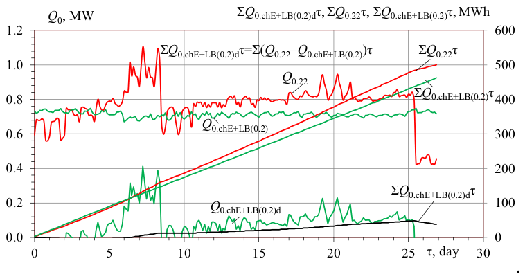
As it is seen, the closeness of the magnitudes of the sum voyage cooling energy ΣQ0.22τ needed for cooling charge air to 22 °С and the available cooling energy ΣQ0.chE+LB(0.2)τ of ECh along the voyage results in reduced sum deficit ΣQ0.chE+LB(0.2)dτ of cooling energy ΣQ0.chE+LB(0.2)τ of ECh due to exhaust heat redistribution between LBCh and ECh.
The results above mentioned indicate the possibility of further reducing the deficit of the available cooling capacities due to increasing the COP of ECh by operation of ECh with a higher COP: at reduced temperatures of refrigerant condensation or at increased its evaporation temperatures in air coolers by application of high efficient heat exchangers with increased heat transfer or through using the addition heat, for instance the heat rejected from diesel engine jacket.
Just as an example, the further reduction or even excluding the deficit ΣQ0.chE+LB(0.2)dτ of cooling energy ΣQ0.chE+LB(0.2)τ of ECh might be achieved due to application of ECh with a bit increased COP=0.22 compared to 0.2 (Figure 9).
As Figure 9 shows, the initial deficit ΣQ0.chE+LB(0.2)dτ of the sum cooling energy of ECh with COP=0.2 of about 0.5 to 1.0MW for cooling charge air to 22 °С is lowered down to ΣQ0.chE+LB(0.22)dτ and even excluded that is justified by the final exceedance ΣQ0.chE+LB(0.22)exτ due to the use of ECh with COP=0.22. The initial average weighted deficit of cooling energy ΣQ0.chE+LB(0.2)dτ = 7.5 % for ECh with COP = 0.2 (Figure 9,b). Whereas there is no average weighted deficit of cooling energy ΣQ0.chE+LB(0.22)dτ = 0 for ECh with COP = 0.22.
The sum effect, gained due to engine cyclic air cooperative cooling to target temperatures by ECh and LBCh with practically twice reduced thermal load and sizes of LBCh, was evaluated by the actual decrease in specific Δbf and total ΣBf amounts of fuel reduction for engine 6S60MC6.1-TI (P=10 MW) over the route (Figure 10).
As Figure 10 shows, the cooling of intake air and charge air by downsized ACh (COP=0.7) and ECh (COP=0.2) ensures a decrease in specific fuel consumption Δbf.E+LB generally by 4.5 to 5.0 g/kWh and total fuel saving ∑Bf.E+LB by about 26 t, which are quite close to their potential magnitudes due to cooling intake air to target 15 °С and charge air to 22 °С with corresponding decrease in Δbf15+22 by 4.7 to 5.2 g/kWh (a) and total fuel saving ∑Bf15+22 by about 27 t (b) for diesel engine 6S60MC6.1-TI during the voyage Odesa-Yokohama.
The additional verification of redistribution of the available heat and cooling capacities accordingly between LBCh and ECh to cover cooling needs Q0.22 and Q0.15 for cooling charge and intake air to 22 °С and 15 °С respectively can be conducted by their comparing with the optimal cooling capacities Q0.ch22opt and Q0.15opt , limiting their minimum design values and chiller's sizes correspondingly, according to advance designing methodology developed by the authors [81].
The method of defining the optimal cooling capacities Q0.ch22opt and Q0.15opt , providing a maximum rate ∑Bf.ch22 /Q0 and ∑Bf.in15 /Q0 of summarized along the ship route fuel saving increment is based on the route fuel saving ∑Bf.ch22 and ∑Bf.in15 samplied (selected) for each design cooling capacities to build a cumulative curve of the route fuel saving depending on design cooling capacities: ∑Bf.ch22 = f(Q0 ) and ∑Bf.in15 = f(Q0 ) (Figure 11 and Figure 12).
With this, the values of route fuel saving ∑Bf.ch22 and ∑Bf.in15 are applied as criteria to find maximum cooling capacities Q0 according to cumulative curves: ∑Bf.ch22 = f(Q0 ) and ∑Bf.in15 = f(Q0 ), meanwhile their relative values ∑Bf.ch22 /Q0 and ∑Bf.in15 /Q0 – as indicators to determine a maximum rate ∑Bf.ch22 /Q0 and ∑Bf.in15 /Q0 of summarized route fuel saving increment and the optimal cooling capacities Q0.ch22opt and Q0.15opt according to derivative curves ∑Bf.ch22 /Q0 = f(Q0 ) and ∑Bf.in15 /Q0 = f(Q0 ) in Figure 11 and Figure 12.
Cumulative current values of fuel saving per route Bf.ch22 samplied precisely for each target definite cooling capacity (thermal load) Q0 during the route, cumulative summerized fuel saving (fuel reduction) per route ∑Bf.ch22 for all target cooling capacities (thermal loads) Q0 within the entire range of thermal loads from 0 to target Q0 were built for cooling scavenge air to 22 °С (Figure 11).
The relative increments of cumulative summerized fuel saving ∑Bf.ch22 /Q0 within the whole range of thermal loads Q0 = 0…Q0.max enable to choose optimal threshold cooling capacity Q0.opt and corresponding fuel saving ∑Bf.sc22opt according to the maximum relative increment (rate) of fuel saving ∑Bf.ch22 /Q0 . (Figure 11).
The maximum value of the relative increment of the route fuel economy ∑Bf.ch22 /Q0 = f(Q0 ) in the whole range of thermal loads Q0 = 0…Q0.max corresponds to the optimal threshold cooling capacity Q0.opt = 860 kW and the route fuel saving Bf.ch22opt = 14 t.
It is worth noting, that the optimal threshold cooling capacity Q0.opt = 860 kW determines the transition from the relatively steep character of the cumulative summarized curve ∑Bf.ch22 = f(Q0 ), i.e. from a close to the maximum rate of increase in the total fuel saving per trip ∑Bf.ch22 to a significant slowdown in the rate of increase in fuel saving ∑Bf.ch22 = f(Q0 ) according to increase in the cooling capacity Q0 .
Thus, the cooling capacity Q0.opt should be considered as a conditionally optimal value, below which a decrease in the design cooling capacity Q0 is unreasonable, since within its range the rate of increase in route fuel saving ∑Bf.ch22 /Q0 is kept relatively stable and close to its maximum. Beyond the threshold value Q0.thr the rate of increase in route fuel saving ∑Bf.ch22 slows down.
On comparing the available Q0.chE+LB(0.2) ≈ 720 kW of ECh (COP=0.2) and generally required cooling capacities Q0.22 ≈ 800 kW for cooling charge air to 22 °C (Figure 7) with optimal threshold cooling capacity Q0.opt = 860 kW the following conclusion can be made concerning the selection of optimal cooling capacity Q0.opt = 860 kW as design value to cover demads Q0.22 ≈ 800 kW or optimal cooling capacity Q0.opt = 860 kW to cover increased needs Q0.22 ≈ 800 kW.
The maximum value of the relative increment of the route fuel economy ∑Bf.in15 /Q0 = f(Q0 ) in the whole range of thermal loads Q0 = 0…Q0.max corresponds to the optimal threshold cooling capacity Q0.opt = 1000 kW and the route fuel saving Bf.in15opt = 9.6 t (Figure 12).
Thus, the cooling capacity Q0.opt should be considered as a conditionally optimal threshold value, below which a decrease in the design cooling capacity Q0 is unreasonable, since within its range the rate of increase in route fuel saving ∑Bf.in15 /Q0 is kept relatively stable and close to its maximum. Beyond the threshold value Q0.thr the rate of increase in route fuel saving ∑Bf.in15 slows down.
On comparing the required cooling capacities Q0.15 from 800 to 1000 kW and even up to 1200 MW for cooling intake air to 15 °C by ACh with COP=0.7 (Figure 4) with optimal threshold cooling capacity Q0.opt = 1000 kW (Figure 12) the following conclusion can be made concerning the selection of optimal threshold cooling capacity Q0.opt = 1000 kW as design value to cover cooling demads Q0.in15 from 800 to 1000 kW.
Further investigation will be focused on development of designing methodology and engine in-cycle air cooling systems adopted to different intake air supply to turbocharger: through special duct or from engine room, accompanied by additional thermal loads caused by heat influx from engine room.
5. Conclusions
Firstly in waste heat recovery cooling of cyclic air in cogeneration marine diesel engine by a high efficient (COP of about 0.7) but cumbersome LBCh unit and comparably low efficient ECh (COP of about 0.2) jointly the possibility to minimize LBCh unit sizes according to practically twice less its loading has been proved that enables its easier placing aboard ship.
A concept of engine cyclic air cooling system with LBCh and ECh based on a general approach to minimize the LBCh sizes through overall thermal load distribution between LBCh and ECh cooling engine inlet to 15 °C and charge air close to 22 °C has been developed to provide a sustainable ship engine operation with stabilized low cyclic air temperatures and high fuel efficiency during the voyage as a result.
Its realization enables to decrease specific fuel consumption Δbf by 3.0 to 4.0 g/kWh at increased ambient and sea water temperatures due to cooperative cooling intake air and charge air, moreover at reduced sizes of the chillers.
The corresponding methodology to determine design thermal loads and cooling capacities of LBCh and ECh chillers, based on comparing their magnitudes available from the exhaust heat with that required for cooling engine cyclic air to target temperatures, was developed to determine boost heat for ECh to cover charge air cooling needs at minimum sizes of LBCh enabling its placing in the engine room.
Nomenclature and Units
| COP | coefficient of performance | |
| DE | diesel engine | |
| ECh | ejector chiller | |
| HRCh | heat recovery chiller | |
| LBCh | lithium-bromide chiller | |
| Symbols and units | ||
| bf | specific fuel consumption | g/kWh |
| Δbf15,22 | specific fuel consumption reduction due to cooling air to 15°C (inlet air), 22°C (charge air) |
g/kWh |
| сma | air specific heat | kJ/(kg·K) |
| G | mass flow rate | kg/s |
| Pe | power | kW |
| Q0 | total cooling capacity | kW |
| ta | air temperature | °C |
| t0 | boiling refrigerant temperature | °C |
| φ | air relative humidity | % |
| τ | time | h |
| Δt | temperature drop | °C; K |
| ΣB | summarized fuel reduction | t |
| ξ | specific heat ratio | |
| Subscripts | ||
| 15, 22 | temperature 15°C, 22°C | |
| a, amb | air, ambient air | |
| in | inlet air | |
| ch | charge air | |
| d | deficit | |
| ex | excess | |
| f | fuel | |
| h | heat | |
| max | maximum | |
Author Contributions
Conceptualization, H.W., R.R. and A.A.; methodology, R.R., A.A, Ar.A, and S.S.; software, R.R., A.A. and Ar.A.; validation, R.R., A.A., Ar.A. and S.S.; formal analysis, H.W., R.R., A.A., H.K., Ar.A. and V.P.; investigation, H.W., R.R., A.A., H.K., Ar.A., S.S. and V.P.; resources, R.R., A.A. and Ar.A.; data curation, R.R., A.A., Ar.A. and V.P.; writing—original draft preparation, R.R., A.A., Ar.A. and S.S.; writing—review and editing, H.W., R.R., H.K. and A.A.; visualization, R.R., A.A., Ar.A. and S.S.; supervision, R.R. and A.A.; project administration, H.W., R.R. and A.A.; funding acquisition, H.W. All authors have read and agreed to the published version of the manuscript.
Funding
This research received no external funding.
Institutional Review Board Statement
Not applicable.
Informed Consent Statement
Not applicable.
Data Availability Statement
Not applicable.
Conflicts of Interest
The authors declare no conflict of interest.
References
- Bistrovic, N.; Bernecic, D. Energy efficiency in maritime transport. In 18th Annual General Assembly of the International Association of Maritime Universities—Global Perspectives in MET: Towards Sustainable, Green and Integrated Maritime Transport; IAMU: Blaj, Romania, 2017; Vol. 32017, pp. 47–50. [Google Scholar]
- Influence of Ambient Temperature Conditions on Main Engine Operation: MAN B&W Diesel A/S; Copenhagen, Denmark, 2010.
- Radchenko, М.; Radchenko, R.; Ostapenko, O.; Zubarev, А.; Hrych, A. Enhancing the utilization of gas engine module exhaust heat by two-stage chillers for combined electricity, heat and refrigeration. 5th International Conference on Systems and Informatics, ICSAI 2018, Jiangsu, Nanjing, China, 2019; pp. 240–244. [Google Scholar] [CrossRef]
- Trushliakov, E.; Radchenko, A.; Forduy, S.; Zubarev, A.; Hrych, A. Increasing the Operation Efficiency of Air Conditioning System for Integrated Power Plant on the Base of Its Monitoring. In Integrated Computer Technologies in Mechanical Engineering (ICTM 2019). Advances in Intelligent Systems and Computing (2020); Nechyporuk, M., Pavlikov, V., Kritskiy, D., Eds.; Springer: Cham, 2020; vol 1113, pp. 351–360. [Google Scholar] [CrossRef]
- Radchenko, A.; Radchenko, N.; Tsoy, A.; Portnoi, B.; Kantor, S. Increasing the efficiency of gas turbine inlet air cooling in actual climatic conditions of Kazakhstan and Ukraine. AIP Conference Proceedings 2020, Coimbatore, India, 17–18 July 2020; AIP Publishing LLC: Melville, NY, USA, 2020; Volume 2285, p. 030071. [Google Scholar] [CrossRef]
- Shukla, A.K.; Singh, O. Thermodynamic investigation of parameters affecting the execution of steam injected cooled gas turbine based combined cycle power plant with vapor absorption inlet air cooling. Appl. Therm. Eng. 2017b, 122, 380–388. [Google Scholar] [CrossRef]
- Shu, G.; Liang, Y.; Wei, H.; Tian, H.; Zhao, J.; Liu, L. A review of waste heat recovery on two-stroke IC engine aboard ships. Renew. Sustain. Energy Rev. 2013, 19, 385–401. [Google Scholar] [CrossRef]
- Pham, V.V. Advanced technology solutions for treatment and control noxious emission of large marine diesel engines: A Brief Review. J. Mech. Eng. Res. Dev. 2019, 42(5), 21–27. [Google Scholar] [CrossRef]
- Radchenko, A.; Radchenko, M.; Koshlak, H.; Radchenko, R.; Forduy, S. Enhancing the efficiency of integrated energy system by redistribution of heat based of monitoring data. Energies 2022, 15, 8774. [Google Scholar] [CrossRef]
- Radchenko, R.; Radchenko, N.; Tsoy, A.; Forduy, S.; Zybarev, A.; Kalinichenko, I. Utilizing the heat of gas module by an absorption lithium-bromide chiller with an ejector booster stage. AIP Conf. Proc. 2020 2020, Volume 2285, 030084. [Google Scholar] [CrossRef]
- Shukla, A.K.; Sharma, A.; Sharma, M.; et al. Performance improvement of simple gas turbine cycle with vapor compression inlet air cooling. Mater. Today Proc. 2018, 5(9), 19172–19180. [Google Scholar] [CrossRef]
- Bassily, A.M. The application of novel techniques for gas turbine inlet-cooling that improve both the power and efficiency of the modern commercial steam-air-cooled gas turbine combined cycle power plants in hot and humid climates. Proceedings of the Institution of Mechanical Engineers, Part A: Journal of Power and Energy 2015, 229(4), 406–430. [Google Scholar] [CrossRef]
- Manzela, A.A.; Hanriot, S.M.; Gomez, L.C.; Sodre, J.R. Using engine exhaust gas as energy source for an absorption refrigeration system. Appl. Energy 2010, 8, 1141–1148. [Google Scholar] [CrossRef]
- Popli, S.; Rodgers, P.; Eveloy, V. Gas turbine efficiency enhancement using waste heat powered absorption chillers in the oil and gas industry. Appl. Therm. Eng. 2013, 50, 918–931. [Google Scholar] [CrossRef]
- Liang, X.; He, G.; Zhou, S.; Hao, Z.; Cai, D. Absorption characteristics of NH3/NaSCN working pair in an adiabatic absorber with structured packing. Appl. Therm. Eng. 2021, 185, 116325. [Google Scholar] [CrossRef]
- Al-Tahaineh, H.A. Cooling of compressor air inlet of a gas turbine power plant using ammonia-water vapor absorption system. Int. J. Energy Eng. 2013, 3(5), 267–271. [Google Scholar]
- Konovalov, D.; Kobalava, H.; Radchenko, M.; Scurtu, I.-C.; Sviridov, V. Determination of the Evaporation Chamber Optimal Length of a Low-Flow Aerothermopressor for Gas Turbines. In Lecture Notes in Mechanical Engineering, Advanced Manufacturing Processes, Selected Papers from the Grabchenko’s International Conference on Advanced Manufacturing Processes (InterPartner-2020); Odessa, Ukraine, Tonkonogyi, V., Ivanov, V., Trojanowska, J., Oborskyi, G., Grabchenko, A., Pavlenko, I., Edl, M., Kuric, I., Dasic, P., Eds.; Springer: Cham, Switzerland, 10–13 September 2020; pp. 654–663. [Google Scholar]
- Petrenko, V.O.; Shestopalov, K.O.; Volovyk, O.S.; Ierin, V.O.; Huang, B.J. Design and modeling of innovative solar ejector air conditioners and chillers operating with low-boiling working fluids. Proc. Int. Conf. on Solar Heating, Cooling and Buildings (EuroSun 2010), Graz, Austria, 28 September - 1 October, 2010. [Google Scholar]
- Radchenko, M.; Radchenko, A.; Trushliakov, E.; Pavlenko, A.; Radchenko, R. Advanced Method of Variable Refrigerant Flow (VRF) System Design to Forecast on Site Operation–Part 3: Optimal Solutions to Minimize Sizes. Energies 2023, 16, 2417. [Google Scholar] [CrossRef]
- Konovalov, D.; Trushliakov, E.; Radchenko, M.; Kobalava, G.; Maksymov, V. Research of the aerothermopresor cooling system of charge air of a marine internal combustion engine under variable climatic conditions of operation. In Lecture Notes in Mechanical Engineering, Advanced Manufacturing Processes, Selected Papers from the Grabchenko’s International Conference on Advanced Manufacturing Processes (InterPartner-2019); Odessa, Ukraine, Tonkonogyi, V., Ivanov, V., Trojanowska, J., Oborskyi, G., Grabchenko, A., Pavlenko, I., Edl, M., Kuric, I., Dasic, P., Eds.; Springer: Cham, Switzerland, 10–13 September 2019; pp. 520–529. [Google Scholar] [CrossRef]
- Konovalov, D.; Radchenko, M.; Kobalava, H.; Radchenko, A.; Radchenko, R.; Kornienko, V.; Maksymov, V. Research of characteristics of the flow part of an aerothermopressor for gas turbine intercooling air. Proc. Inst. Mech. Eng. Part A J. Power Energy, 2021. [Google Scholar] [CrossRef]
- Yu, Z.; Løvås, T.; Konovalov, D.; Trushliakov, E.; Radchenko, M.; Kobalava, H.; Radchenko, R.; Radchenko, A. Investigation of thermopressor with incomplete evaporation for gas turbine intercooling systems. Energies 2023, 16, 20. [Google Scholar] [CrossRef]
- Dolinsky, A.A.; Klimenko, V.N.; Sabashuk, P.P. Conditions for the effective use of additional fuel combustion in CCGT. Ecotechnologies Resour. Sav. 2003, 2, 8–13. [Google Scholar]
- Dolinsky, A.A.; Basok, B.I.; Kolomeiko, D.A. Efficiency of cogeneration thermal schemes. Hayek Work. 2006, 61(48), 30–38. [Google Scholar]
- Fumo, N.; Mago, P.J.; Smith, A.D. Analysis of combined cooling, heating, and power systems operating following the electric load and following the thermal load strategies with no electricity export. Proceedings of the Institution of Mechanical Engineers, Part A Journal of Power and Energy 2011, 225(8), 1016–1025.6180. [Google Scholar] [CrossRef]
- Radchenko, A.; Radchenko, M.; Konovalov, A.; Zubarev, A. Increasing electrical power output and fuel efficiency of gas engines in integrated energy system by absorption chiller scavenge air cooling on the base of monitoring data treatment. HTRSE-2018, E3S Web Conf. 2018, 70, 03011. [Google Scholar] [CrossRef]
- Kornienko, V.; Radchenko, R.; Radchenko, M.; Radchenko, A.; Pavlenko, A.; Konovalov, D. Cooling cyclic air of marine engine with water-fuel emulsion combustion by exhaust heat recovery chiller. Energies 2022, 15(1), 248. [Google Scholar] [CrossRef]
- Radchenko, M.; Mikielewicz, D.; Andreev, A.; Vanyeyev, S.; Savenkov, O. Efficient ship engine cyclic air cooling by turboexpander chiller for tropical climatic conditions. In Lecture Notes in Networks and Systems, Advances in Intelligent Systems and Computing, International Scientific and Technical Conference on Integrated Computer Technologies in Mechanical Engineering—Synergetic Engineering, ICTM 2020; Kharkiv, Ukraine, Nechyporuk, M., Pavlikov, V., Kritskiy, D., Eds.; Springer: Cham, Switzerland, 29–30 October 2020; Volume 188, pp. 498–507. [Google Scholar] [CrossRef]
- Bohdal, L.; Kukielka, L.; Świłło, S.; Radchenko, A.M.; Kułakowska, A. Modelling and experimental analysis of shear-slitting process of light metal alloys using FEM, SPH and vision-based methods. AIP Conf. Proc. Published Online. 2019, 2078, 020060. [Google Scholar] [CrossRef]
- Radchenko, M.; Radchenko, R.; Kornienko, V.; Pyrysunko, M. Semi-Empirical Correlations of Pollution Processes on the Condensation Surfaces of Exhaust Gas Boilers with Water-Fuel Emulsion Combustion. In Advances in Design, Simulation and Manufacturing II. DSMIE 2019. Lecture Notes in Mechanical Engineering (LNME). Springer, Cham (2020); Ivanov, V., et al., Eds.; Springer Nature Switzerland AG, 2019; pp. 853–862. [Google Scholar] [CrossRef]
- Basok, B.I.; Bazeev, E.T.; Didenko, V.M.; Kolomeyko, D.A. Analysis of cogeneration plants. Part I Classification and main indicators. Ind. Heat Eng. 2006, 28(3), 83–89. [Google Scholar]
- Basok, B.I.; Kolomeiko, D.A.; Kuzhel, P.M. Energy and environmental performance of a cogeneration plant with an electrical output of 1.0 MW and a thermal output of 1.2 MW. Ind. Heat Eng. 2009, 31(2), 42–49. [Google Scholar]
- Radchenko, A.; Mikielewicz, D.; Forduy, S.; Radchenko, M.; Zubarev, A. Monitoring the fuel efficiency of gas engine in integrated energy system. In Lecture Notes in Networks and Systems, Advances in Intelligent Systems and Computing, International Scientific and Technical Conference on Integrated Computer Technologies in Mechanical Engineering—Synergetic Engineering, ICTM 2019; Kharkiv, Ukraine, Nechyporuk, M., Pavlikov, V., Kritskiy, D., Eds.; Springer: Cham, Switzerland; Springer: Cham, 28–30 November 2019; pp. 361–370. [Google Scholar] [CrossRef]
- Forduy, S.; Radchenko, A.; Kuczynski, W.; Zubarev, A.; Konovalov, D. Enhancing the fuel efficiency of gas engines in integrated energy system by chilling cyclic air. In Lecture Notes in Mechanical Engineering, Advanced Manufacturing Processes, Selected Papers from the Grabchenko’s International Conference on Advanced Manufacturing Processes (InterPartner-2019), Odessa, Ukraine, 10–13 September 2019; Tonkonogyi, V., Ivanov, V., Trojanowska, J., Oborskyi, G., Grabchenko, A., Pavlenko, I., Edl, M., Kuric, I., Dasic, P., Eds.; Springer: Cham, Switzerland, 2020; pp. 500–509. [Google Scholar]
- MAN Diesel Turbo, CEAS Engine Calculations. 2019. Available online: https://marine.man-es.com/two-stroke/ceas.
- MAN B&W ME/ME-C/ME-GI/ME-B-TII engines; MAN Diesel: Copenhagen, Denmark, 2010; p. 389 р.
- Ayhan, V.; Ece, Y.M. New application to reduce NOx emissions of diesel engines: Electronically controlled direct water injection at compression stroke. Appl. Energy 2020, 260. [Google Scholar] [CrossRef]
- Xia, J.; Wang, J.; Lou, J.; Hu, J.; Yao, S. Thermodynamic, economic, environmental analysis and multi-objective optimization of a novel combined cooling and power system for cascade utilization of engine waste heat. Energy 2023. [Google Scholar] [CrossRef]
- Patel, K.R.; Dhiman, V.D. A review on emission and performance of water diesel micro-emulsified mixture-diesel engine. Int. J. Environ. Sci. Technol. 2022, 19, 8027–8042. [Google Scholar]
- Wang, S.; Liu, Z.; Liu, C.; Wang, X. Thermodynamic analysis of operating strategies for waste heat recovery of combined heating and power systems. Energy 2022, 258, 124803. [Google Scholar] [CrossRef]
- Zhu, P.; Yao, J.; Qian, C.; Yang, F.; Porpatham, E.; Zhang, Z.; Wu, Z. High-efficiency conversion of natural gas fuel to power by an integrated system of SOFC, HCCI engine, and waste heat recovery: Thermodynamic and thermo-economic analyses. Fuel 2020. [Google Scholar] [CrossRef]
- Tian, C.; Su, C.; Yang, C.; Wei, X.; Pang, P.; Xu, J. Exergetic and economic evaluation of a novel integrated system for cogeneration of power and freshwater using waste heat recovery of natural gas combined cycle. Energy 2022. [Google Scholar] [CrossRef]
- Kornienko, V.; Radchenko, R.; Mikielewicz, D.; Pyrysunko, M.; Andreev, A. Improvement of Characteristics of Water-Fuel Rotary Cup Atomizer in a Boiler. In Advanced Manufacturing Processes II. InterPartner 2020. Lecture Notes in Mechanical Engineering; Tonkonogyi, V., et al., Eds.; Springer: Cham, 2021; pp. 664–674. [Google Scholar]
- Kavvadias, K.C.; Tosios, A.P.; Maroulis, Z.B. Design of a combined heating, cooling and power system: sizing, operation strategy selection and parametric analysis. Energy Convers. Manag. 2010, 51, 833–845. [Google Scholar] [CrossRef]
- Wang, S.; Liu, Z.; Liu, C.; Wang, X. Thermodynamic analysis of operating strategies for waste heat recovery of combined heating and power systems. Energy 2022. [Google Scholar] [CrossRef]
- Radchenko, R.; Pyrysunko, M.; Kornienko, V.; Scurtu, I.-C.; Patyk, R. Improving the ecological and energy efficiency of internal combustion engines by ejector chiller using recirculation gas heat. In Lecture Notes in Networks and Systems. Integrated Computer Technologies in Mechanical Engineering - 2020. ICTM 2020; Nechyporuk, M., Pavlikov, V., Kritskiy, D., Eds.; Springer: Cham, 2021; Volume 188, pp. 531–541. [Google Scholar]
- Mito, M.T.; Teamah, M.A.; El-Maghlany, W. M.; Shehata, A.I. Utilizing the charge air cooling in improving the performance of marine Diesel engine waste heat recovery systems. Energy 2018, 142, 264–276. [Google Scholar] [CrossRef]
- Maritime Absorption Chiller - HEINEN & HOPMAN heinenhopman.com.
- Riaz, F.; Tan, K.H.; Farooq, M.; Imran, M.; Lee, P.S. Energy Analysis of a Novel Ejector-Compressor Cooling Cycle Driven by Electricity and Heat (Waste Heat or Solar Energy). Sustainability 2020, 12, 8178. [Google Scholar] [CrossRef]
- Tashtoush, B.; Megdouli, K.; Elakhdar, M.; Nehdi, E.; Kairouani, L. A Comprehensive Energy and Exergoeconomic Analysis of a Novel Transcritical Refrigeration Cycle. Processes 2020, 8, 758. [Google Scholar] [CrossRef]
- Li, C.; Yan, J.; Li, Y.; Cai, W.; Lin, C.; Chen, H. Experimental study on a multi-evaporator refrigeration system with variable area ratio ejector. Appl. Therm. Eng. 2016, 102, 196–203. [Google Scholar] [CrossRef]
- Chen, H.; Zhu, J.; Lu, W. Optimized selection of one- and two-stage ejectors under design and off-design conditions. Energy Convers. Manag. 2018, 173, 743–752. [Google Scholar] [CrossRef]
- Ierin, V.; Chen, G.; Volovyk, O.; Shestopalov, K. Hybrid two – stage CO2 transcritical mechanical compression – ejector cooling cycle: Thermodynamic analysis and optimization. Int. J. Refrig. 2021, 132, 45–55. [Google Scholar] [CrossRef]
- Chen, G.; Zhelezny, V.; Khliyeva, O.; Shestopalov, K.; Ierin, V. Ecological and energy efficiency analysis of ejector and vapor compression air conditioners. Int. J. Refrig. 2017, 74, 127–135. [Google Scholar] [CrossRef]
- Bohdal, T.; Sikora, M.; Widomska, K.; Radchenko, A. M. Investigation of flow structures during HFE-7100 refrigerant condensation; Archives of thermodynamics: Polish Academy of Sciences, 2015; Vol. 36, no. 4, pp. 25–34. [Google Scholar] [CrossRef]
- Tarasova, V.; Kuznetsov, M.; Kharlampidi, D.; Kostikov, A. Development of a vacuum-evaporative thermotransformer for the cooling system at a nuclear power plant. East.-Eur. J. Enterp. Technol. 2019, 4/8(100), 45–56. [Google Scholar] [CrossRef]
- Pavlenko, A. Change of emulsion structure during heating and boiling. Int. J. Energy A Clean. Environ. 2019, 20(4), 291–302. [Google Scholar] [CrossRef]
- Pavlenko, A.; Koshlak, H.; Basok, B.; Hrabova, T. Thermomechanical Homogenization in Steam Explosion. Rocz. Ochr. Sr. 2023, 25, 9–15. [Google Scholar] [CrossRef]
- Radchenko, N.I. On reducing the size of liquid separators for injector circulation plate freezers. Int. J. Refrig. 1985, 8(5), 267–269. [Google Scholar] [CrossRef]
- Radchenko, N. A concept of the design and operation of heat exchangers with change of phase. Arch. Thermodyn. 2004, 25(4), 3−19. [Google Scholar]
- Patel, N.; Modi, M.; Patel, T. Investigation of diesel engine with water emulsifier - A review. Int. Res. J. Eng. Technol. 2017, 4(2), 879–883. [Google Scholar] [CrossRef]
- Rules for Classification Ships, Part 6, Additional class notations, Chapter 7. Environmental protection and pollution control. In Edition DNV GL AS; July 2019.
- Konovalov, D.; Kobalava, H.; Radchenko, M.; Scurtu, I.C.; Radchenko, R. Determination of hydraulic resistance of the aerothermopressor for gas turbine cyclic air cooling. TE-RE-RD 2020, E3S Web Conf. 2020, vol. 180, 01012. [Google Scholar] [CrossRef]
- Kornienko, V.; Radchenko, R.; Bohdal, Ł.; Kukiełka, L.; Legutko, S. Investigation of condensing heating surfaces with reduced corrosion of boilers with water-fuel emulsion combustion. In Integrated Computer Technologies in Mechanical Engineering - 2020. ICTM 2020. Lecture Notes in Networks and Systems; Nechyporuk, M., Pavlikov, V., KrIESkiy, D., Eds.; Springer: Cham, 2021; vol 188, pp. 300–309. [Google Scholar]
- Kornienko, V.; Radchenko, R.; Bohdal, T.; Radchenko, M.; Andreev, A. Thermal characteristics of the wet pollution layer on condensing heating surfaces of exhaust gas boilers. In Advances in Design, Simulation and Manufacturing IV. DSMIE 2021. Lecture Notes in Mechanical Engineering; Ivanov, V., Pavlenko, I., Liaposhchenko, O., Machado, J., Edl, M., Eds.; Springer: Cham, Switzerland, 2021; pp. 339–348. [Google Scholar] [CrossRef]
- Yang, Z.; Kornienko, V.; Radchenko, M.; Radchenko, A.; Radchenko, R.; Pavlenko, A. Capture of pollutants from exhaust gases by low-temperature heating surfaces. Energies 2022, 15(1), 120. [Google Scholar] [CrossRef]
- Wojs, M.K.; Orliński, P.; Kamela, W.; Kruczyński, P. Research on the influence of ozone dissolved in the fuel-water emulsion on the parameters of the CI engine. IOP Conference Series: Materials Science and Engineering, 2016; 148, pp. 1–8. [Google Scholar]
- Pavlenko, A. Energy conversion in heat and mass transfer processes in boiling emulsions. Therm. Sci. Eng. Prog. 2020, 15, 00439. [Google Scholar] [CrossRef]
- Kornienko, V.; Radchenko, M.; Radchenko, R.; Bohdal, Ł.; Andreev, A. Thermal Characteristics of the Wet Pollution Layer on Condensing Heating Surfaces of Exhaust Gas Boilers. In Lecture Notes in Mechanical Engineering; pp. с. 339–348.
- Serbin, S.; Radchenko, M.; Pavlenko, A.; Burunsuz, K.; Radchenko, A.; Chen, D. Improving Ecological Efficiency of Gas Turbine Power System by Combusting Hydrogen and Hydrogen-Natural Gas Mixtures. Energies 2023, 16(9), 3618. [Google Scholar] [CrossRef]
- Radchenko, M.; Radchenko, A.; Trushliakov, E.; Pavlenko, A.M.; Radchenko, R. Advanced method of variable refrigerant flow (VRF) systems designing to forecast on site operation–Part 1: General approaches and criteria. Energies 2023, 16, 1381. [Google Scholar] [CrossRef]
- Radchenko, M.; Radchenko, A.; Trushliakov, E.; Koshlak, H.; Radchenko, R. Advanced method of variable refrigerant flow (VRF) systems designing to forecast on site operation– Part 2: Phenomenological simulation to recuperate refrigeration energy. Energies 2023, 16, 1922. [Google Scholar] [CrossRef]
- Konovalov, D.; Kobalava, H.; Maksymov, V.; Radchenko, R.; Avdeev, M. Experimental Research of the Excessive Water Injection Effect on Resistances in the Flow Part of a Low-Flow Aerothermopressor. In Advances in Design, Simulation and Manufacturing III (DSMIE 2020). Lecture Notes in Mechanical Engineering; Ivanov, V., et al., Eds.; Springer: Cham, 2020; pp. 292–301. [Google Scholar]
- Trushliakov, E.; Radchenko, M.; Radchenko, A.; Kantor, S.; Zongming, Y. Statistical Approach to Improve the Efficiency of Air Conditioning System Performance in Changeable Climatic Conditions. 5th International Conference on Systems and Informatics, ICSAI 2018, Jiangsu, Nanjing, China, 2019; pp. 256–260. [Google Scholar] [CrossRef]
- Bartnik, R.; Buryn, Z.; Hnydiuk-Stefan, A.; Skomudek, W.; Otawa, A. Thermodynamic and Economic Analysis of Trigeneration System Comprising a Hierarchical Gas-Gas Engine for Production of Electricity, Heat and Cold. Energies 2020, 13, 1006. [Google Scholar] [CrossRef]
- Radchenko, A.; Trushliakov, E.; Tkachenko, V.; Portnoi, B.; Prjadko, O. Improvement of the Refrigeration Capacity Utilizing for the Ambient Air Conditioning System. In Advanced Manufacturing Processes II. InterPartner 2020. Lecture Notes in Mechanical Engineering; Tonkonogyi, V., et al., Eds.; Springer: Cham, 2021; pp. 714–723. [Google Scholar]
- Radchenko, M.; Radchenko, R.; Tkachenko, V.; Kantor, S.; Smolyanoy, E. Increasing the Operation Efficiency of Railway Air Conditioning System on the Base of Its Simulation Along the Route Line. In Integrated Computer Technologies in Mechanical Engineering (ICTM 2019). Advances in Intelligent Systems and Computing (2020); Nechyporuk, M., Pavlikov, V., Kritskiy, D., Eds.; Springer: Cham, 2020; vol 1113, pp. 461–467. [Google Scholar] [CrossRef]
- Khliyeva, O.; Shestopalov, K.; Ierin, V.; Zhelezny, V.; Chen, G.; Neng, G. Environmental and energy comparative analysis of expediency of heat-driven and electrically-driven refrigerators for air conditioning application. Appl. Therm. Eng. 2023, 219, 119533. [Google Scholar] [CrossRef]
- Radchenko, A.; Bohdal, L.; Zongming, Y.; Portnoi, B.; Tkachenko, V. Rational designing of gas turbine inlet air cooling system. Lecture Notes in Mechanical Engineering, Advanced Manufacturing Processes, Selected Papers from the Grabchenko’s International Conference on Advanced Manufacturing Processes (InterPartner-2019), Odessa, Ukraine, 10–13 September 2019, Tonkonogyi V, Switzerland, 2020; pp. 591–599. [Google Scholar] [CrossRef]
- Kornienko, V.; Radchenko, R.; Konovalov, D.; Andreev, A.; Pyrysunko, M. Characteristics of the Rotary Cup Atomizer Used as Afterburning Installation in Exhaust Gas Boiler Flue. In Advances in Design, Simulation and Manufacturing III (DSMIE 2020). Lecture Notes in Mechanical Engineering; Ivanov, V., et al., Eds.; Springer: Cham, 2020; pp. 302–311. [Google Scholar]
- Radchenko, M.; Radchenko, A.; Mikielewicz, D.; Radchenko, R.; Andreev, A. A novel degree-hour method for rational design loading. Proc. Inst. Mech. Eng. Part A Journal of Power and Energy, 2022. [Google Scholar] [CrossRef]
- Radchenko, N.; Trushliakov, E.; Radchenko, A.; Tsoy, A.; Shchesiuk, O. Methods to determine a design cooling capacity of ambient air conditioning systems in climatic conditions of Ukraine and Kazakhstan. AIP Conf. Proc. 2020 2020, Volume 2285, 030074. [Google Scholar] [CrossRef]
- Radchenko, A.; Radchenko, M.; Trushliakov, E.; Kantor, S.; Tkachenko, V. Statistical Method to Define Rational Heat Loads on Railway Air Conditioning System for Changeable Climatic Conditions. 5th International Conference on Systems and Informatics, ICSAI 2018, Jiangsu, Nanjing, China, 2019; pp. 1294–1298. [Google Scholar] [CrossRef]
- Radchenko, N.; Radchenko, A.; Tsoy, A.; Mikielewicz, D.; Kantor, S.; Tkachenko, V. Improving the efficiency of railway conditioners in actual climatic conditions of operation. AIP Conference Proceedings 2020, Coimbatore, India, 17–18 July 2020; AIP Publishing LLC: Melville, NY, USA, 2020; Volume 2285, p. 030072. [Google Scholar] [CrossRef]
- Yang, Z.; Radchenko, R.; Radchenko, M.; Radchenko, A.; Kornienko, V. Cooling potential of ship engine intake air cooling and its realization on the route line. Sustainability 2022, 14 1, 5058. [Google Scholar] [CrossRef]
- Kornienko, V.; Radchenko, R.; Stachel, A.; Andreev, A.; Pyrysunko, M. Correlations for pollution on condensing surfaces of exhaust gas boilers with water-fuel emulsion combustion. In Grabchenko’s International Conference on Advanced Manufacturing Processes. InterPartner-2019. Lecture Notes in Mechanical Engineering.; Tonkonogyi, V., et al., Eds.; Springer: Cham, 2020; pp. 530–539. [Google Scholar] [CrossRef]
- Radchenko, R.; Kornienko, V.; Pyrysunko, M.; Bogdanov, M.; Andreev, A. Enhancing the Efficiency of Marine Diesel Engine by Deep Waste Heat Recovery on the Base of Its Simulation Along the Route Line. In Integrated Computer Technologies in Mechanical Engineering (ICTM 2019). Advances in Intelligent Systems and Computing (2020); Nechyporuk, M., Pavlikov, V., Kritskiy, D., Eds.; Springer: Cham; vol 1113, pp. 337–350. [CrossRef]
- Trushliakov, E.; Radchenko, A.; Radchenko, M.; Kantor, S.; Zielikov, O. The Efficiency of Refrigeration Capacity Regulation in the Ambient Air Conditioning Systems. In Advances in Design, Simulation and Manufacturing III (DSMIE 2020). Lecture Notes in Mechanical Engineering; Ivanov, V., et al., Eds.; Springer: Cham, 2020; pp. 343–353. [Google Scholar]
- Rahim, M.A. Performance and sensitivity analysis of a combined cycle gas turbine power plant by various inlet air-cooling systems. Proceedings of the Institution of Mechanical Engineers, Part A: Journal of Power and Energy 2012, 226(7), 922–931. [Google Scholar] [CrossRef]
- Shukla, A.K.; Singh, O. Impact of inlet fogging on the performance of Steam injected cooled gas turbine based combined cycle power plant. In Proceedings of the ASME 2017 Gas Turbine India Conference, Bangalore, India, December 7 – 8, 2017; Volume 1, p. 2017a. [Google Scholar] [CrossRef]
- Yang, Ch.; Yang, Z.; Cai, R. Analytical method for evaluation of gas turbine inlet air cooling in combined cycle power plant. Appl. Energy 2009, 86, 848–856. [Google Scholar] [CrossRef]
- Pan, M.; Lu, F.; Zhu, Y.; Huang, G.; Yin, J.; Huang, F.; Chen, G.; Chen, Z. Thermodynamic, exergoeconomic and multi-objective optimization analysis of new ORC and heat pump system for waste heat recovery in waste-to-energy combined heat and power plant. Energy Convers. Manag. 2020. [Google Scholar] [CrossRef]
- Trushliakov, E.; Radchenko, M.; Bohdal, T.; Radchenko, R.; Kantor, S. An innovative air conditioning system for changeable heat loads. In Grabchenko’s International Conference on Advanced Manufacturing Processes. InterPartner-2019. Lecture Notes in Mechanical Engineering.; Tonkonogyi, V., et al., Eds.; Springer: Cham, 2020; pp. 616–625. [Google Scholar] [CrossRef]
- Radchenko, A.; Stachel, A.; Forduy, S.; Portnoi, B.; Rizun, O. Analysis of the Efficiency of Engine Inlet Air Chilling Unit with Cooling Towers. In Advances in Design, Simulation and Manufacturing III (DSMIE 2020). Lecture Notes in Mechanical Engineering; Ivanov, V., et al., Eds.; Springer: Cham, 2020; pp. 322–331. [Google Scholar]
- Qu, J.; Feng, Y.; Zhu, Y.; Zhou, S.; Zhang, W. Design and thermodynamic analysis of a combined system including steam Rankine cycle, organic Rankine cycle, and power turbine for marine low-speed diesel engine waste heat recovery. Energy Convers. Manag. 2021. [Google Scholar] [CrossRef]
- Yang, Z.; Kornienko, V.; Radchenko, M.; Radchenko, A.; Radchenko, R. Research of Exhaust Gas Boiler Heat Exchange Surfaces with Reduced Corrosion when Water-fuel Emulsion Combustion. Sustainability 2022, 14, 11927. [Google Scholar] [CrossRef]
- CEAS Engine Calculations: Planning Tools and Downloads. Available online: https://www.everllence.com/marine/products/planning-tools-and-downloads/ceas-engine-calculations/ (accessed on 09 Marc 2026).
Figure 1.
Schemes of a typical exhaust heat recovery system (a) and its developed version for cooling intake and charge air (b): C and Т – compressor and a turbine of the turbocharger; SS – steam separator; SC-WH – steam condenser-water heater; Ec – economizer section of steam condenser; HC – heat consumer; CC – condensate cooler; CC-Gec – condensate cooler-economizer section of ECh generator; Ac – accumulator of water; P – pump; E – ejector; Con – condenser; EV – expansion valve; E-WC – refrigerant evaporator-water cooler; ACh– absorption chiller: Ga – generator; Ea – evaporator; A – absorber; HExh – heat exchanger; SACHТ – high-temperature (cogeneration) section of the charge (scavenge) air cooler; SACSW – seawater cooling stage; SACLТ – low-temperature section of the charge (scavenge) air cooler; AC – intake air cooler; DC – drop catcher; Cond – condensate; SW– sea water.
Figure 1.
Schemes of a typical exhaust heat recovery system (a) and its developed version for cooling intake and charge air (b): C and Т – compressor and a turbine of the turbocharger; SS – steam separator; SC-WH – steam condenser-water heater; Ec – economizer section of steam condenser; HC – heat consumer; CC – condensate cooler; CC-Gec – condensate cooler-economizer section of ECh generator; Ac – accumulator of water; P – pump; E – ejector; Con – condenser; EV – expansion valve; E-WC – refrigerant evaporator-water cooler; ACh– absorption chiller: Ga – generator; Ea – evaporator; A – absorber; HExh – heat exchanger; SACHТ – high-temperature (cogeneration) section of the charge (scavenge) air cooler; SACSW – seawater cooling stage; SACLТ – low-temperature section of the charge (scavenge) air cooler; AC – intake air cooler; DC – drop catcher; Cond – condensate; SW– sea water.
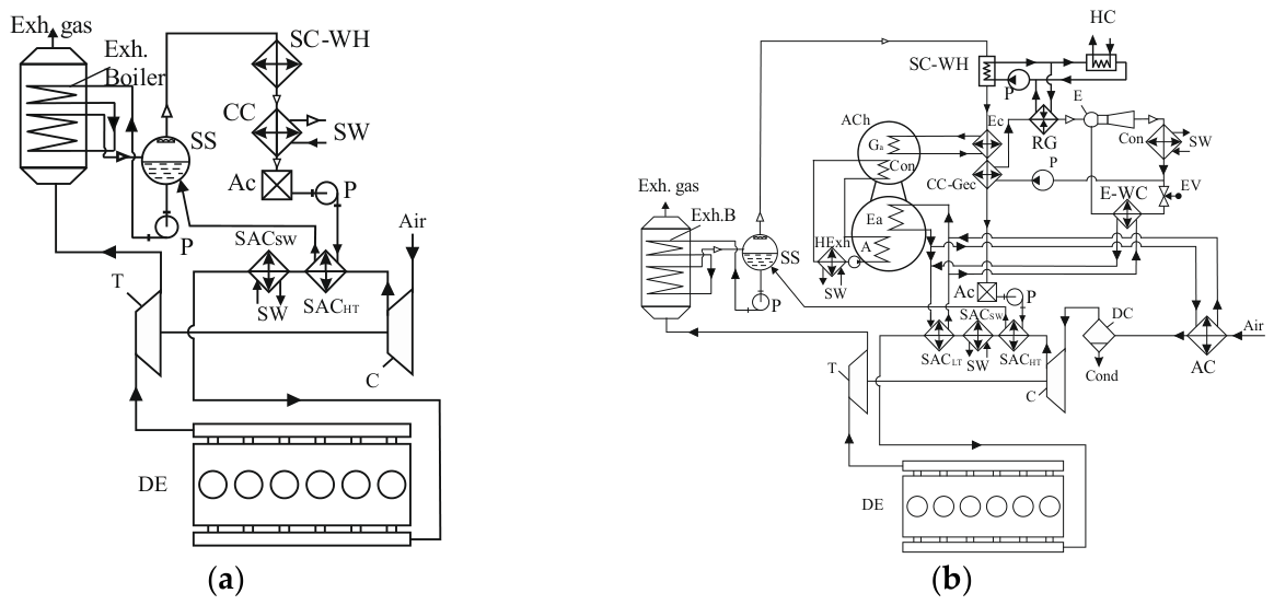
Figure 2.
The variations in temperatures ta and relative humidity φa of ambient air as well as temperatures of sea water tsw (a) and charge air cooled by sea water ta (b) along the target route.
Figure 2.
The variations in temperatures ta and relative humidity φa of ambient air as well as temperatures of sea water tsw (a) and charge air cooled by sea water ta (b) along the target route.
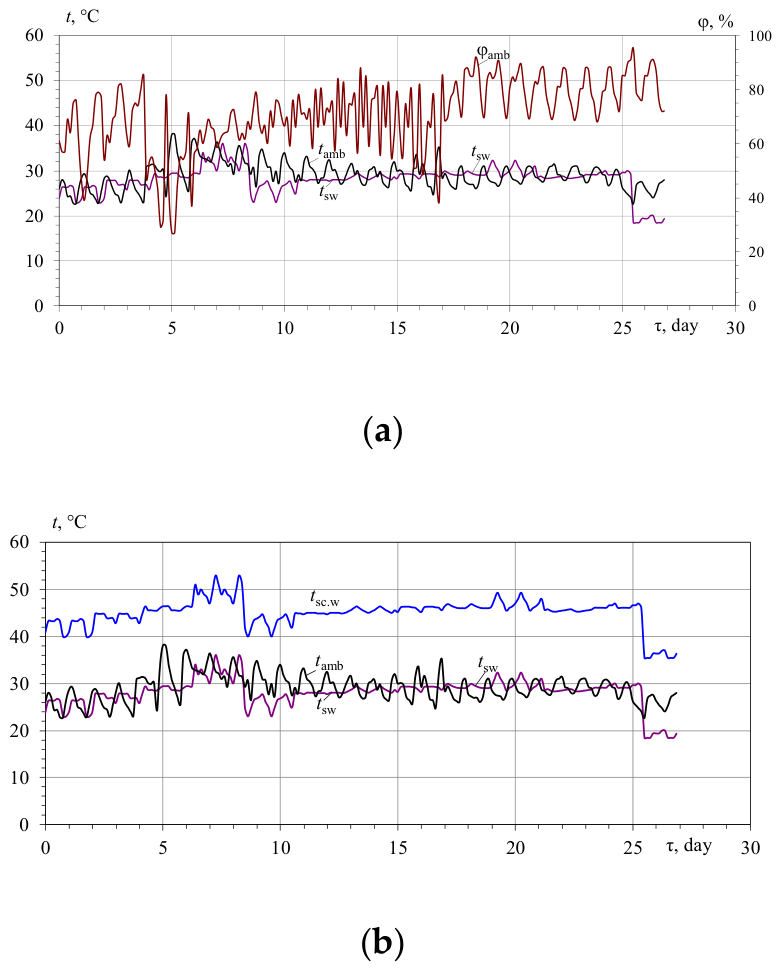
Figure 3.
The values of available heat of exhaust gas Qexh and charge air Qch and their summation Qexh+ch (a), the excesses Qh15+22LB(0.7)ex of the sum heat Qexh+ch over the heat needs for cooling inlet air to 15 °С and charge air to 22 °С by LBCh (COP= 0.7) and heat deficit Qh15+22E(0.2)d for ECh (COP = 0.2) (b) during the voyage.
Figure 3.
The values of available heat of exhaust gas Qexh and charge air Qch and their summation Qexh+ch (a), the excesses Qh15+22LB(0.7)ex of the sum heat Qexh+ch over the heat needs for cooling inlet air to 15 °С and charge air to 22 °С by LBCh (COP= 0.7) and heat deficit Qh15+22E(0.2)d for ECh (COP = 0.2) (b) during the voyage.
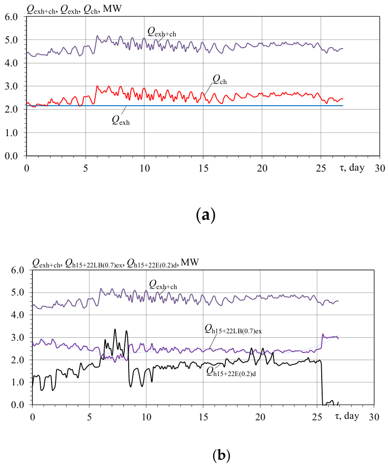
Figure 4.
The values of the available exhaust heat Qexh , required heat Qh15LB for intake air cooling by LBCh (COP=0.7) to 15 °С and exceedances QexhLBex15 of exhaust heat Qexh over the required heat Qh15LB for intake air cooling to 15 °С by LBCh during the target voyage: Qh15LB = Q0.15 /COP, where Q0.15 – cooling capacities needed for cooling intake air to 15 °С, COP=0.7 for LBCh.
Figure 4.
The values of the available exhaust heat Qexh , required heat Qh15LB for intake air cooling by LBCh (COP=0.7) to 15 °С and exceedances QexhLBex15 of exhaust heat Qexh over the required heat Qh15LB for intake air cooling to 15 °С by LBCh during the target voyage: Qh15LB = Q0.15 /COP, where Q0.15 – cooling capacities needed for cooling intake air to 15 °С, COP=0.7 for LBCh.
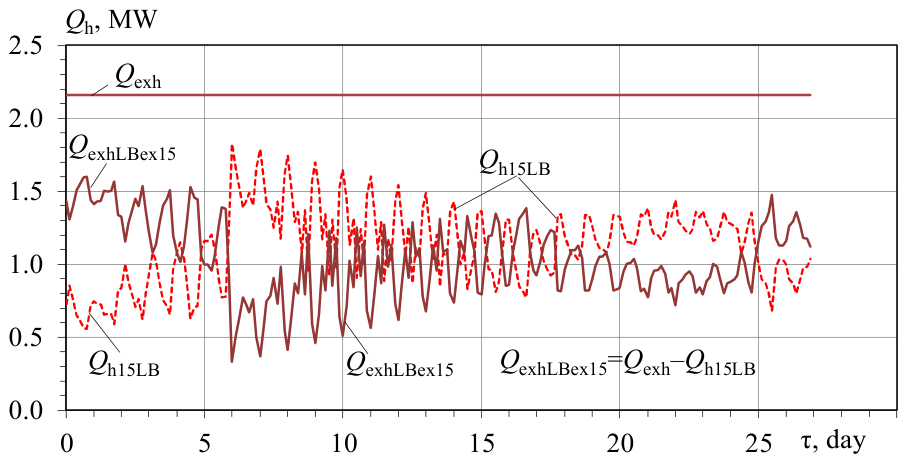
Figure 5.
Cooling capacities Q0.22 required for cooling charge air to 22 °С, available cooling capacities Q0.chE of ECh with COP = 0.2 and deficit Q0.chE.d of ECh cooling capacities for cooling charge air to 22 °С during the target voyage: Q0.chE.d = Q0.22 – Q0.chE ; Q0.chE = Qch COP, where COP=0.2.
Figure 5.
Cooling capacities Q0.22 required for cooling charge air to 22 °С, available cooling capacities Q0.chE of ECh with COP = 0.2 and deficit Q0.chE.d of ECh cooling capacities for cooling charge air to 22 °С during the target voyage: Q0.chE.d = Q0.22 – Q0.chE ; Q0.chE = Qch COP, where COP=0.2.
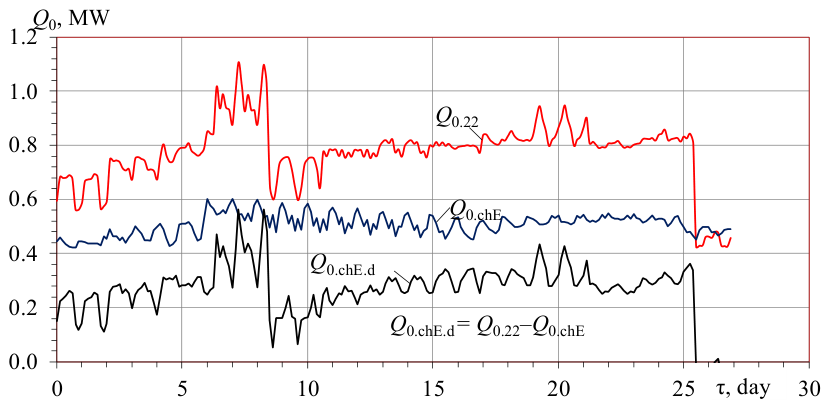
Figure 6.
The heat needs Qh22E for charge air cooling by ECh (COP = 0.2) to 22 °С, the sum available heat QchE+LB of charge air Qch and exceedant exhaust gas heat QexhLBex15 (Figure 4) left from LBCh, the charge air heat deficit QchE.d and deficit QchE+LB.d of the overall heat: QchE+LB.d = Qch + QexhLBex15 .
Figure 6.
The heat needs Qh22E for charge air cooling by ECh (COP = 0.2) to 22 °С, the sum available heat QchE+LB of charge air Qch and exceedant exhaust gas heat QexhLBex15 (Figure 4) left from LBCh, the charge air heat deficit QchE.d and deficit QchE+LB.d of the overall heat: QchE+LB.d = Qch + QexhLBex15 .
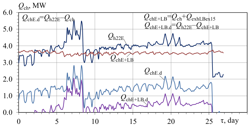
Figure 7.
Cooling capacities Q0.22 required for charge air cooling to 22 °С, available cooling capacities Q0.chE of ECh (COP=0.2) using the heat of charge air, the sum Q0.chE+LB(0.2) of the available cooling capacities of ECh using charge air heat Q0.chE and the rest exhaust gas heat from LBCh Q0.LB(0.2) , initial deficit of cooling capacities Q0.chE.d of ECh, final deficit Q0.chE+LB(0.2)d of the sum cooling capacities Q0.chE+LB(0.2) of ECh.
Figure 7.
Cooling capacities Q0.22 required for charge air cooling to 22 °С, available cooling capacities Q0.chE of ECh (COP=0.2) using the heat of charge air, the sum Q0.chE+LB(0.2) of the available cooling capacities of ECh using charge air heat Q0.chE and the rest exhaust gas heat from LBCh Q0.LB(0.2) , initial deficit of cooling capacities Q0.chE.d of ECh, final deficit Q0.chE+LB(0.2)d of the sum cooling capacities Q0.chE+LB(0.2) of ECh.
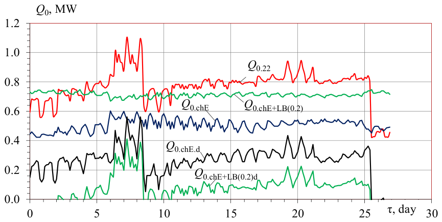
Figure 9.
Voyage cooling energy balances for charge air cooling to 22 °C using ejector chillers (ECh) at COP = 0.2 and 0.22: (a) Cumulative cooling energy deficits (ΣQ0.chE(0.2)d22τ, ΣQ0.chE(0.22)d22τ), exhaust gas waste heat excesses ΣQ0.LB(0.2)exτ, ΣQ0.LB(0.22)exτ, and combined deficits/exceedances (ΣQ0.chE+LB(0.2)dτ , ΣQ0.chE+LB(0.22)dτ, ΣQ0.chE+LB(0.22)exτ; (b) Average weighted cooling energy deficit ΣQ0.chE+LB(0.2)dτ for ECh at COP = 0.2.
Figure 9.
Voyage cooling energy balances for charge air cooling to 22 °C using ejector chillers (ECh) at COP = 0.2 and 0.22: (a) Cumulative cooling energy deficits (ΣQ0.chE(0.2)d22τ, ΣQ0.chE(0.22)d22τ), exhaust gas waste heat excesses ΣQ0.LB(0.2)exτ, ΣQ0.LB(0.22)exτ, and combined deficits/exceedances (ΣQ0.chE+LB(0.2)dτ , ΣQ0.chE+LB(0.22)dτ, ΣQ0.chE+LB(0.22)exτ; (b) Average weighted cooling energy deficit ΣQ0.chE+LB(0.2)dτ for ECh at COP = 0.2.
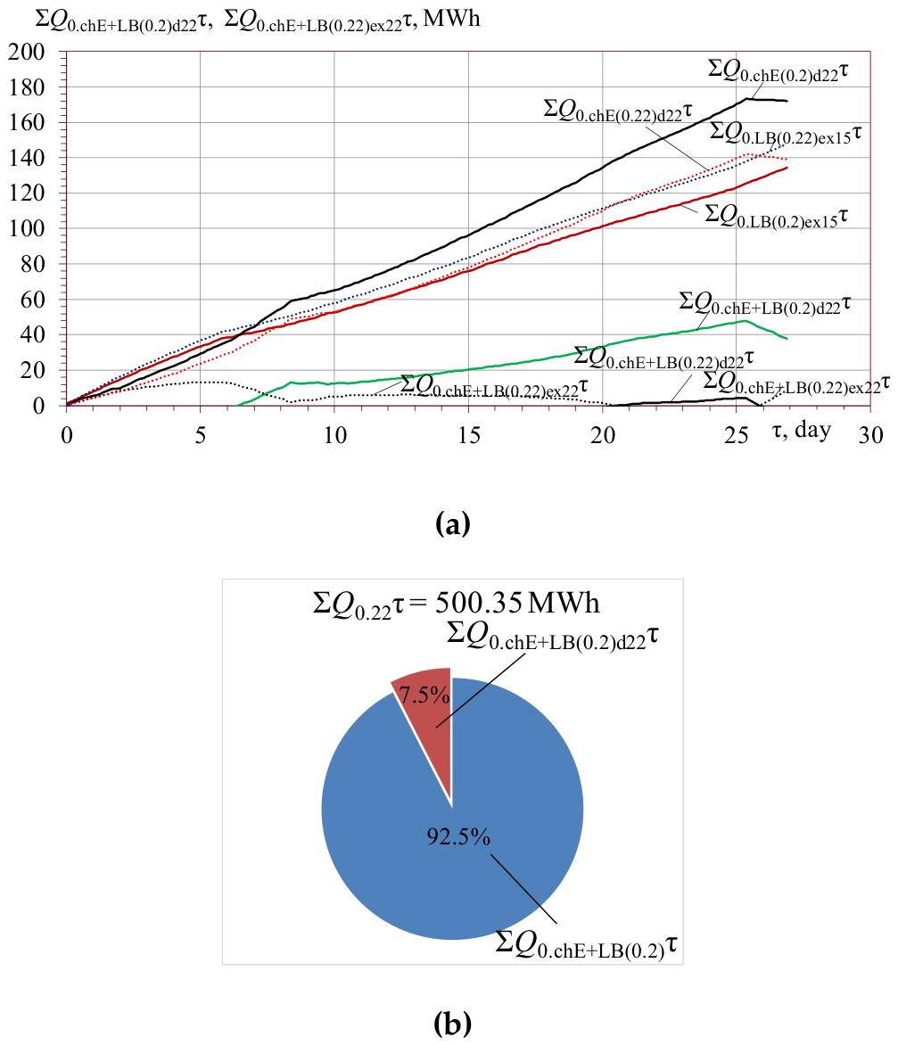
Figure 10.
Actual and potential fuel reduction parameters for a 10 MW 6S60MC6.1-TI marine engine operating on the Odesa–Yokohama route, utilising LBCh (intake air cooled to 15 °C) and ECh (charge air cooled to 22 °C, COP = 0.2): (a) Specific Δbf.E+LB, Δbf15+22 and total cumulative ∑Bf.E+LB, ∑Bf15+22 fuel savings, alongside their respective operational deficits Δbf.E+LB.d, ∑Bf.E+LB.d over the voyage duration; (b) Distribution of the actual total fuel reduction ∑Bf.E+LB and the unfulfilled deficit ∑Bf.E+LB.d relative to the maximum potential savings.
Figure 10.
Actual and potential fuel reduction parameters for a 10 MW 6S60MC6.1-TI marine engine operating on the Odesa–Yokohama route, utilising LBCh (intake air cooled to 15 °C) and ECh (charge air cooled to 22 °C, COP = 0.2): (a) Specific Δbf.E+LB, Δbf15+22 and total cumulative ∑Bf.E+LB, ∑Bf15+22 fuel savings, alongside their respective operational deficits Δbf.E+LB.d, ∑Bf.E+LB.d over the voyage duration; (b) Distribution of the actual total fuel reduction ∑Bf.E+LB and the unfulfilled deficit ∑Bf.E+LB.d relative to the maximum potential savings.
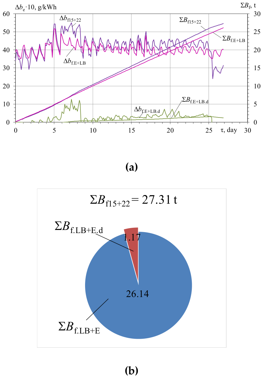
Figure 11.
Cumulative summerized fuel saving ∑Bf.ch22 , relative increments of cumulative summerized fuel saving ∑Bf.ch22 /Q0 , optimal threshold cooling capacity Q0.ch.opt and fuel saving ∑Bf.ch22opt at maximum relative increment (rate) of fuel saving ∑Bf.ch22 /Q0 for cooling charge air to 22 °C.
Figure 11.
Cumulative summerized fuel saving ∑Bf.ch22 , relative increments of cumulative summerized fuel saving ∑Bf.ch22 /Q0 , optimal threshold cooling capacity Q0.ch.opt and fuel saving ∑Bf.ch22opt at maximum relative increment (rate) of fuel saving ∑Bf.ch22 /Q0 for cooling charge air to 22 °C.
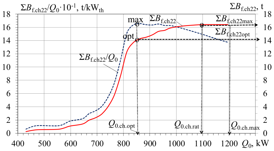
Figure 12.
Cumulative summerized fuel saving ∑Bf.in15 , relative increments of cumulative summerized fuel saving ∑Bf.in /Q0 , optimal threshold cooling capacity Q0.opt and fuel saving ∑Bf.in15opt at maximum relative increment (rate) of fuel saving ∑Bf.in15 /Q0 for cooling intake ambient air to 15°C.
Figure 12.
Cumulative summerized fuel saving ∑Bf.in15 , relative increments of cumulative summerized fuel saving ∑Bf.in /Q0 , optimal threshold cooling capacity Q0.opt and fuel saving ∑Bf.in15opt at maximum relative increment (rate) of fuel saving ∑Bf.in15 /Q0 for cooling intake ambient air to 15°C.
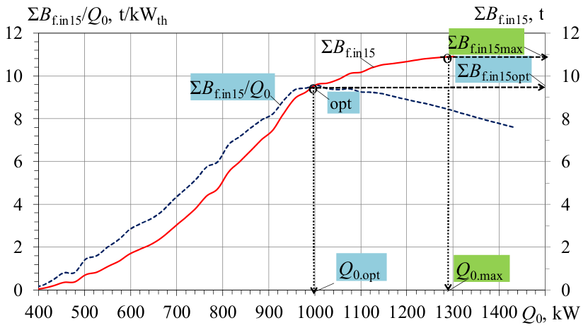

Table 1.
Change in specific fuel consumption Δbe ,%, under climatic conditions other than ta = 25 ºС; P = 1 bar; φ = 60%, according to data of Diesel engine "MAN" [29].
Table 1.
Change in specific fuel consumption Δbe ,%, under climatic conditions other than ta = 25 ºС; P = 1 bar; φ = 60%, according to data of Diesel engine "MAN" [29].
| Parameter |
Change in parameter |
Δbe, g/kWh | Δbe, % | Deviation,% |
| temperature of charge air cooling water | increment for each 10°c | 1.1 | +0.6 | ±3 |
| temperature of air at the inlet of turbocharger | increment for each 10°c | 1.2 | +0.7 | ±3 |
Disclaimer/Publisher’s Note: The statements, opinions and data contained in all publications are solely those of the individual author(s) and contributor(s) and not of MDPI and/or the editor(s). MDPI and/or the editor(s) disclaim responsibility for any injury to people or property resulting from any ideas, methods, instructions or products referred to in the content. |
© 2026 by the authors. Licensee MDPI, Basel, Switzerland. This article is an open access article distributed under the terms and conditions of the Creative Commons Attribution (CC BY) license.
Copyright: This open access article is published under a Creative Commons CC BY 4.0 license, which permit the free download, distribution, and reuse, provided that the author and preprint are cited in any reuse.