
Submitted:
07 July 2026
Posted:
08 July 2026
You are already at the latest version
Abstract
Microcomb-based microwave photonic (MWP) transversal filter systems have been an attractive platform for microwave signal processing owing to their wide operation bandwidth and high reconfigurability. Despite the rapid advances in demonstrating diverse processing functions, the radiofrequency (RF) performance of such systems has not yet been systematically characterized and benchmarked. In this work, we optimize a microcomb-based MWP transversal filter system and experimentally characterize its RF performance when configured as a low-pass filter. The measured RF link gain, noise figure, and spurious-free dynamic range (SFDR) are -5.16 dB, 12.32 dB, and 107.7 dB/Hz2/3, respectively, representing an improvement over our previously reported microcomb-based MWP transversal filter system. A benchmark comparison with state-of-the-art MWP filters shows that the microcomb-based MWP transversal filter system can achieve competitive and well-balanced RF performance. This work provides valuable insight into the RF characteristics of microcomb-based transversal filter systems and offers guidance for their continued development toward real-world applications.
Keywords:
microwave photonics
; RF performance
; optical microcombs
; integrated optics
I. INTRODUCTION
With the increasing demand for high-speed data processing, electronic signal processing is increasingly constrained by its intrinsic bandwidth limitations [1]. In contrast, photonic signal processing can overcome this bottleneck and provide orders-of-magnitude higher processing speeds, making it highly attractive for high-speed information processing [2]. Among various photonic signal processing approaches, microwave photonics (MWP) has emerged as a promising platform for microwave signal processing, owing to its broad operation bandwidth and strong immunity to electromagnetic interference [3]. Within this area, transversal filter systems are especially attractive because they offer a high degree of reconfigurability [4].
In MWP transversal filter systems, different wavelength channels from a multiwavelength source serve as discrete taps for synthesizing radiofrequency (RF) frequency response [5]. Optical microcombs [6,7,8], generated from high-quality(Q)-factor microresonators, provide a compact and scalable multiwavelength source, offering large comb spacings and hence wide Nyquist bands compared with conventional mode-locked laser combs [9,10]. With the ability to flexibly control the tap weights and time delays between the comb lines, microcomb-based transversal filter systems can achieve high reconfigurability. This has enabled the system to implement a wide range of microwave signal processing functions [6,11,12].
Although diverse applications have been demonstrated, the RF performance of microcomb-based MWP transversal filter systems remains insufficiently characterized and benchmarked, which is important for practical system deployment. For real-world applications, the RF performance directly affects the fidelity, added noise, and nonlinear distortion of output signals [13]. Therefore, a systematic characterization of the RF performance is essential for evaluating whether microcomb-based MWP transversal filter systems can move beyond proof-of-concept demonstrations toward practical deployment. The key metrics for evaluating the RF performance of the system are RF link gain, noise figure, and spurious-free dynamic range (SFDR), consistent with the standard evaluation of conventional analogue MWP links [14]. In addition, in MWP systems, the aforementioned three metrics are closely coupled through their shared dependence on optical power, noise contributions, and nonlinear distortion [15,16]. Therefore, achieving well-balanced RF performance across all three metrics remains challenging, which makes simultaneous optimization of these key metrics essential.
In this work, we optimize a microcomb-based MWP transversal filter system by simplifying the optical spectral shaping configuration, reducing the number of employed taps, and using a photodetector with higher responsivity. We experimentally characterize the RF performance of the optimized system, using a low-pass MWP filter as a representative example. It achieves an RF link gain of -5.16 dB, a noise figure of 12.32 dB, and an SFDR of 107.7 dB/Hz2/3, respectively. Compared with our previous work [17], these results show substantial improvements, verifying the effectiveness of the optimized system. Finally, when benchmarked against state-of-the-art MWP filters, the proposed system exhibits the lowest reported noise figure, an SFDR in the upper quartile, and an RF link gain above the median, showing that our system achieves competitive and well-balanced RF performance. These results provide quantitative insights into the RF performance of microcomb-based MWP transversal filter systems and offer useful guidance for future system optimization and practical applications.
II. Principle
Figure 1 shows the schematic diagram of an MWP transversal filter system, in which an optical microcomb serves as a multi-wavelength source, providing a large number of discrete wavelength channels (i.e., taps). The tap weights are encoded in the optical power of comb lines through optical spectral shaping. Next, an input microwave signal is multicast onto different wavelength channels by using an intensity modulator (IM), after which time delays between adjacent channels are introduced by a dispersive module. Finally, the weighted and delayed signals are combined via a photodetector (PD) and converted back into a microwave signal as the final system output.
The spectral transfer function of the MWP transversal filter system in Figure 1 can be expressed as [5]
where M is the number of taps, an (n = 0, 1, 2, …, M-1) is the tap weight of the nth tap, and Δt is the time delay between adjacent taps. By applying calculated an on each wavelength channel, different processing functions with arbitrary H(ω) can be implemented [5,17].
RF metrics, including RF link gain, noise figure, and SFDR, are usually adopted to characterize the RF performance of an MWP system [14]. The RF link gain of the system characterizes the overall efficiency of microwave signal transfer from the input to the output. At a given frequency f, the RF link gain can be expressed by [14]
where Pout and Pin are the output and input power of the microwave signal, respectively. A higher GRF(f) corresponds to more efficient microwave signal transmission and is hence desirable for improved RF performance. The noise figure evaluates the extent to which system-inherent noise deteriorates the signal-to-noise ratio (SNR) during transmission, and can be defined as [14]
where SNRin and SNRout are the SNRs of the input and output microwave signals, respectively, with the input noise assumed to be dominated only by thermal noise. A lower noise figure is beneficial as it indicates less degradation of the signal-to-noise ratio introduced by the system. The SFDR quantifies the maximum range of input signal power over which the fundamental signal remains above the noise floor while the third-order intermodulation distortion (IMD3) components remain below it [14]. It is commonly evaluated using a two-tone test [18] by analyzing the output powers of the fundamental signals and the IMD3 components at different input powers. By linearly extrapolating the measured data, the third-order input intercept point IIP3 can be obtained, from which the third-order SFDR is given by [14]
where Nth is the input thermal noise power spectral density. A higher SFDR corresponds to a wider usable dynamic range before nonlinear distortion becomes dominant, indicating better linearity performance of the system.
GRF(f) = 10log10(Pout / Pin)
NF = 10log10(SNRin / SNRout)
For an MWP transversal filter system, the RF performance can be improved by reducing optical insertion loss, employing an appropriate number of taps, and improving the optical-to-electrical (OE) and electrical-to-optical (EO) conversion efficiencies. These help enhance the RF link gain and noise figure while avoiding significant degradation of the system linearity, thus supporting a more balanced RF performance.
III. Experimental results
In this work, the multi-wavelength source was provided by a soliton crystal microcomb generated from an integrated microring resonator (MRR). As a unique class of optical frequency combs, soliton crystal microcombs are characterized by self-organized ensembles of multiple co-propagating solitons arranged in a crystal-like structure in the angular domain [6,19]. The microcomb was generated using an MRR fabricated on a complementary metal-oxide-semiconductor (CMOS)-compatible doped silica platform [20,21]. The MRR had a Q factor of ~1.9 million and a radius of ~592 μm, which corresponded to a free spectral range (FSR) of ~48.9 GHz (i.e., ~0.4 nm). The soliton crystal microcomb was achieved using a simple pump-wavelength sweeping method [22]. As shown in Figure 2a, a continuous-wave (CW) pump laser (Yenista Optics) was amplified to ~32.1 dBm with an erbium-doped fibre amplifier (EDFA, IdealPhotonics) and then was swept from blue to red in wavelength until modulation instability driven oscillation were observed. With further adjustment of the pump-resonance detuning, a stable soliton crystal state was achieved. As shown in Figure 2b, this state produced more than 90 comb lines (i.e., wavelength channels) across the C band, with a pump wavelength of ~1551.3 nm.
To characterize the RF performance of the system, a low-pass filter response, as shown in Figure 2c, was synthesized. The low-pass MWP filter was implemented by spectrally shaping the generated soliton crystal microcomb with a Waveshaper (Coherent) into 5 taps with equal weights (i.e., an = 1). The shaped comb lines were then fed into an IM (iXBlue), yielding replicas of the input microwave signal. Next, the modulated signal was transmitted through a spool of single-mode fibre (SMF) with a dispersion of ~87.0 ps nm-1, corresponding to a Δt of ~34.8 ps. The operation bandwidth of the low-pass filter was inversely related to the time delay between adjacent wavelength channels, which was 1/2Δt = ~14.4 GHz. Finally, the weighted and delayed replicas were combined upon photodetection and converted back to the microwave domain, and the RF response of the filter (Figure 2c) was measured by using a vector network analyzer (VNA, Anritsu).
Compared with our previous work [17], where two-stage spectral shaping, 41 taps, and a photodetector with responsivity of 0.45 A/W were employed, the proposed system has been optimized by simplifying the spectral-shaping configuration to alleviate insertion loss, reducing the number of taps to minimize undesired amplitude and phase errors across all taps, and using a photodetector with a responsivity of 0.6 A/W to enhance the OE conversion efficiency.
The RF link gain and noise figure were measured by applying an input microwave signal with a power of ~2.68 dBm (Figure 3a) to the IM and recording the output signal (Figure 3b) after photodetection. The power of the output signal was ~-2.48 dBm, which corresponded to an RF link gain of -5.16 dB according to Eq. (2). Based on Eq. (3), the noise figure was calculated to be 12.32 dB.
A two-tone test [18] centred at 1 GHz was performed by simultaneously feeding two CW microwave signals at 1 GHz and 1.01 GHz, with equal power, to the IM. The input power of the two-tone signal varied from ~-7.58 dBm to ~-0.25 dBm, while the corresponding output signals from the PD (Coherent) were monitored. The resulting IMD3 components at 0.99 GHz and 1.02 GHz were recorded (Figure 4a), indicating an SFDR of 107.7 dB⋅Hz2/3 as shown in Figure 4b.
Compared with our previous work in Ref. [17], the proposed system has shown an improved RF performance. In this work, the higher-responsivity PD enhanced the OE conversion efficiency, improving the RF link gain and noise figure. The reduced tap number (i.e., M = 5) in the proposed system played a major role in the improved SFDR. As the number of wavelength channels increases, it becomes more difficult to maintain uniformly linear modulation, making the imperfect response of the IM and PD contribute more significantly to the IMD3 in the combined output. In addition, only one Waveshaper was used, which reduced the optical insertion loss, enhancing the RF link gain.
The main factors limiting the RF link gain were optical losses in the system [14], together with low OE/EO conversion efficiency [23]. The optical losses can be further compensated for by employing low-loss optical components. The OE/EO conversion efficiency can be further improved by using an IM with a lower half-wave voltage Vπ [24] and a PD with higher responsivity [25]. The noise figure is mainly limited by optical losses and noise. By using a low-noise EDFA can reduce the amplified spontaneous emission (ASE) noise while providing sufficient optical power, thereby improving the noise figure [16].
According to Eq. (4), SFDR is jointly determined by the noise floor and nonlinear distortion, so it can be improved by enhancing the OE/EO conversion efficiency, employing low-noise components, and ensuring linear operation of the IM and PD. IMD3 suppression technique has been used to achieve a high SFDR of 123 dB⋅Hz2/3 [26], but at the expense of increased configuration complexity and additional loss, making it more difficult to maintain high RF link gain and low noise figure.
IV. Benchmarking of RF performance against state-of-the-art MWP filters
Table 1 and the corresponding box plots in Figure 5 provide a benchmark comparison of the key RF metrics of state-of-the-art MWP filters based on different mechanisms. MWP filters based on Bragg-grating-based spectral filtering [27,28], microresonator-based spectral filtering [29,30,31,32,33], stimulated Brillouin scattering [34,35], ring-assisted interferometric filtering [26,36,37,38], and photonic-phononic emitter-receiver filtering [39,40] realize filtering functions through specific physical mechanisms, which themselves introduce insertion loss, noise, and nonlinear distortion. In addition, they often rely on additional microresonators, interferometric paths, or Brillouin-active components, which can introduce extra insertion loss, require precise bias control or phase control, or increase susceptibility to noise and nonlinear distortion. These factors make it difficult to simultaneously achieve high RF link gain, low noise figure, and high linearity. In contrast, in a transversal filter system, the filtering response is synthesized by the combination of weighted and delayed microwave replicas. Therefore, the resulting RF performance is influenced mainly by the performance of the components in the MWP link, including insertion loss, noise, OE/EO conversion efficiency, and linearity, rather than by the underlying mechanism.
In our system, the soliton crystal microcomb offered low-noise comb lines generated through an adiabatic process [12], which contributed to the low noise figure. In addition, an EDFA was placed after the Waveshaper to compensate for the insertion loss, and the PD’s responsivity of 0.6 A/W provided high OE conversion efficiency. As can be seen from Figure 5, our results fall within the high-performance range for all the three RF metrics. The noise figure is the best reported value, the SFDR is in the upper quartile, and the RF link gain is above the median. This indicates that our system achieves a competitive RF performance and an overall balance among the three key RF metrics. The RF performance can be further improved by employing a low-noise EDFA in the MWP link to reduce ASE noise, an IM with lower Vπ to achieve higher EO conversion efficiency [24], given that the IM used here had a relatively high Vπ of 7V, and an RF amplifier to increase the RF link gain and decrease the noise figure [39].
We note that Refs. [26,32] have also reported strong RF performance through optimization of the modulator’s operating conditions and, in the latter case, implementing the IMD3 suppression technique. The advantage of our system is that an optical microcomb served as the multiwavelength source in the transversal filter system, which provided a highly reconfigurable architecture that was attractive for a broader range of MWP signal processing applications. We note that, in our previous work [17], two Waveshapers have been employed to ensure high shaping accuracy, with the benefit of supporting an ultrasteep roll-off response, which introduced higher shaping loss, degrading the RF performance. This indicates an inherent trade-off between reconfigurability and RF performance in the microcomb-based transversal filter system. More advanced or complex functions require a larger number of taps and more accurate spectral shaping, which tends to increase system loss and make high-linearity operation more difficult. In highly reconfigurable architectures, strong overall RF performance can be maintained by compensating the additional loss using RF amplification [39] and improving the link linearity through IMD3 suppression techniques [26]. This work has broad implications for microcombs [41,42,43,44,45,46,47,48,49,50,51,52,53,54,55,56,57,58,59,60,61,62,63,64,65,66,67,68,69,70,71] and their applications to microwave photonics, neuromorphic processors and communications. [72,73,74,75,76,77,78,79,80,81,82,83,84,85,86,87,88,89,90,91,92,93,94,95,96,97,98,99,100,101,102,103,104,105,106,107,108,109,110,111,112,113,114,115,116,117,118,119,120,121,122,123,124] The addition and use of 2D materials [125,126,127,128,129,130,131,132,133,134,135,136,137,138,139,140,141,142,143,144,145,146,147,148,149,150,151,152,153,154,155,156,157,158,159,160,161,162,163,164,165,166,167] will add extra functionality to microcomb chips for potential applications to quantum photonics [168,169,170,171,172,173,174,175,176,177,178,179,180,181,182,183] and other areas. [184,185,186,187,188,189,190,191,192,193,194,195,196,197,198,199,200,201]
V. Conclusion
In summary, we have experimentally investigated the RF performance of a microcomb-based MWP transversal filter system by using a low-pass MWP filter as an example. The system achieved an RF link gain of -5.16 dB, a noise figure of 12.32 dB, and an SFDR of 107.7 dB/Hz2/3. Benchmarking against previously reported MWP filters confirms the competitive overall RF performance of our system, with the noise figure being the lowest reported to date. These results offer a quantitative basis for evaluating the RF characteristics of microcomb-based MWP transversal filter systems and provide useful insight for their future optimization and practical applications.
References
- Wang, J.; et al. Microcomb-enabled parallel self- calibration optical convolution streaming processor. Light Sci. Appl. 2026/03/05 2026, vol. 15(no. 1), 149. [Google Scholar] [CrossRef] [PubMed]
- Shekhar, S.; et al. Roadmapping the next generation of silicon photonics. Nat. Commun. 2024/01/25 2024, vol. 15(no. 1), 751. [Google Scholar] [CrossRef] [PubMed]
- Yao, J. Microwave Photonic Systems. J. Light. Technol. 2022, vol. 40(no. 20), 6595–6607. [Google Scholar] [CrossRef]
- Sun, Y.; et al. Optimizing the Accuracy of Microcomb-Based Microwave Photonic Transversal Signal Processors. J. Light. Technol. 2023, vol. 41(no. 23), 7223–7237. [Google Scholar] [CrossRef]
- Sun, Y.; et al. Quantifying the Accuracy of Microcomb-Based Photonic RF Transversal Signal Processors. IEEE J. Sel. Top. Quantum Electron.;Photonic Signal Process. 2023, vol. 29(no. 6), 1–17. [Google Scholar] [CrossRef]
- Sun, Y.; et al. Applications of optical microcombs. Adv. Opt. Photon. 2023/03/31 2023, vol. 15(no. 1), 86–175. [Google Scholar] [CrossRef]
- Corcoran, B.; Mitchell, A.; Morandotti, R.; Oxenløwe, L. K.; Moss, D. J. Optical microcombs for ultrahigh-bandwidth communications. Nat. Photonics vol. 19(no. 5), 451–462, 2025/05/01 2025. [CrossRef]
- Kippenberg, T. J.; Gaeta, A. L.; Lipson, M.; Gorodetsky, M. L. Dissipative Kerr solitons in optical microresonators. Science 2018, vol. 361(no. 6402). [Google Scholar]
- Jones, D. J.; et al. Carrier-envelope phase control of femtosecond mode-locked lasers and direct optical frequency synthesis. Science 2000, vol. 288(no. 5466), 635–639. [Google Scholar] [CrossRef] [PubMed]
- Kim, J.; Song, Y. Ultralow-noise mode-locked fiber lasers and frequency combs: principles, status, and applications. Adv. Opt. Photon. 2016, vol. 8(no. 3), 465–540. [Google Scholar] [CrossRef]
- Shu, H.; et al. Microcomb-driven silicon photonic systems. Nature 2022/05/01 2022, vol. 605(no. 7910), 457–463. [Google Scholar] [CrossRef] [PubMed]
- Xu, X.; et al. 11 TOPS photonic convolutional accelerator for optical neural networks. Nature 2021/01/01 2021, vol. 589(no. 7840), 44–51. [Google Scholar] [CrossRef]
- Williams, K. J. “Signal Processing Subsystems for RF Photonics,” in Optical Fiber Communication Conference. OSA Technical Digest (online), Los Angeles, California, 2017/03/19 2017; Optica Publishing Group; p. W4B.1. Available online: https://opg.optica.org/abstract.cfm?URI=OFC-2017-W4B.1. [CrossRef]
- Liu, Y.; Choudhary, A.; Marpaung, D.; Eggleton, B. J. Integrated microwave photonic filters. Adv. Opt. Photon. 2020/06/30 2020, vol. 12(no. 2), 485–555. [Google Scholar] [CrossRef]
- Cox, C. H. Analog Optical Links: Theory and Practice; Cambridge University Press, 2006. [Google Scholar]
- Ackerman, E. I.; Cox, C. H. RF fiber-optic link performance. IEEE Microw. Mag. 2001, vol. 2(no. 4), 50–58. [Google Scholar] [CrossRef]
- Li, Y.; et al. Reconfigurable Microwave Photonic Filters with Ultrasteep Roll-Off Based on Optical Microcombs. Laser Photon. Rev. 2026/01/02 2026, vol. n/a, no. n/a, e01910. [Google Scholar] [CrossRef]
- Garrett, M.; et al. Integrated microwave photonic notch filter using a heterogeneously integrated Brillouin and active-silicon photonic circuit. Nat. Commun. 2023/11/20 2023, vol. 14(no. 1), 7544. [Google Scholar] [CrossRef]
- Cole, D. C.; Lamb, E. S.; Del’Haye, P.; Diddams, S. A.; Papp, S. B. Soliton crystals in Kerr resonators. Nat. Photonics 2017/10/01 2017, vol. 11(no. 10), 671–676. [Google Scholar] [CrossRef]
- Razzari, L.; et al. CMOS-compatible integrated optical hyper-parametric oscillator. Nat. Photonics 2010/01/01 2010, vol. 4(no. 1), 41–45. [Google Scholar] [CrossRef]
- Moss, D.; Morandotti, R.; Gaeta, A. L.; Lipson, M. “New CMOS-compatible platforms based on silicon nitride and Hydex for nonlinear optics,”. Nat. Photonics Review (in English). 2013, vol. 7(no. 8), 597–607. [Google Scholar] [CrossRef]
- Wang, W.; et al. Robust soliton crystals in a thermally controlled microresonator. Opt. Lett. 2018/05/01 2018, vol. 43(no. 9), 2002–2005. [Google Scholar] [CrossRef] [PubMed]
- Urick, V. J.; Williams, K. J.; McKinney, J. D. Fundamentals of microwave photonics; John Wiley & Sons, 2015. [Google Scholar]
- Kamada, S.; Ueda, R.; Yamada, C.; Tanaka, K.; Yamada, T.; Otomo, A. Superiorly low half-wave voltage electro-optic polymer modulator for visible photonics. Opt. Express 2022/05/23 2022, vol. 30(no. 11), 19771–19780. [Google Scholar] [CrossRef] [PubMed]
- Sun, M.; et al. Ultrafast evanescently coupled waveguide MUTC-PDs with high responsivity. Opt. Express vol. 32(no. 9), 16455–16466. [CrossRef]
- Daulay, et al. Ultrahigh dynamic range and low noise figure programmable integrated microwave photonic filter. Nat. Commun. 2022/12/17 2022, vol. 13(no. 1), 7798. [Google Scholar] [CrossRef] [PubMed]
- Gao, L.; Zhang, J.; Chen, X.; Yao, J. Microwave Photonic Filter With Two Independently Tunable Passbands Using a Phase Modulator and an Equivalent Phase-Shifted Fiber Bragg Grating. IEEE Trans. Microw. Theory Tech. 2014, vol. 62(no. 2), 380–387. [Google Scholar] [CrossRef]
- Porzi, C.; Reza, M.; Ghelfi, P.; Sorel, M.; Bogoni, A. Silicon-on-Insulator Microwave Photonic Filter With Widely Tunable and Reconfigurable Flat-Top Bandpass Functionality. J. Light. Technol. 2022, vol. 40(no. 20), 6666–6675. [Google Scholar] [CrossRef]
- Daulay; Liu, G.; Marpaung, D. Microwave photonic notch filter with integrated phase-to-intensity modulation transformation and optical carrier suppression. Opt. Lett. 2021/02/01 2021, vol. 46(no. 3), 488–491. [Google Scholar] [CrossRef] [PubMed]
- Li, J.; Yang, S.; Chen, H.; Chen, M. Hybrid microwave photonic receiver based on integrated tunable bandpass filters. Opt. Express vol. 29(no. 7), 11084–11093. [CrossRef]
- Liu, Y.; Chen, Y.; Wang, L.; Yu, Y.; Yu, Y.; Zhang, X. Tunable and Reconfigurable Microwave Photonic Bandpass Filter Based on Cascaded Silicon Microring Resonators. J. Light. Technol. 2022, vol. 40(no. 14), 4655–4662. [Google Scholar] [CrossRef]
- Liu, Y.; Hotten, J.; Choudhary, A.; Eggleton, B. J.; Marpaung, D. All-optimized integrated RF photonic notch filter. Opt. Lett. 2017/11/15 2017, vol. 42(no. 22), 4631–4634. [Google Scholar] [CrossRef] [PubMed]
- Daulay; Botter, R.; Marpaung, D. On-chip programmable microwave photonic filter with an integrated optical carrier processor. OSA Contin. vol. 3(no. 8), 2166–2174. [CrossRef]
- Liu, Y.; et al. Integration of Brillouin and passive circuits for enhanced radio-frequency photonic filtering. APL Phontonics 2019, vol. 4(no. 10). [Google Scholar] [CrossRef]
- Garrett, M.; et al. Multi-Band and Frequency-Agile Chip-Based RF Photonic Filter for Ultra-Deep Interference Rejection. J. Light. Technol. 2022, vol. 40(no. 6), 1672–1680. [Google Scholar] [CrossRef]
- Fandino, J. S.; Munoz, P.; Domenech, D.; Capmany, J. “A monolithic integrated photonic microwave filter,”. Nat. Photonics Article (in English). 2017, vol. 11(no. 2), 124–129. [Google Scholar] [CrossRef]
- Tao, Y.; et al. Hybrid-integrated high-performance microwave photonic filter with switchable response. Photonics Res. 2021/08/01 2021, vol. 9(no. 8), 1569–1580. [Google Scholar] [CrossRef]
- Rady, R.; Madsen, C.; Palermo, S.; Entesari, K. A 20–43.5-GHz Wideband Tunable Silicon Photonic Receiver Front-End for mm-wave Channel Selection/Jammer Rejection. J. Light. Technol. 2023, vol. 41(no. 5), 1309–1324. [Google Scholar] [CrossRef]
- Gertler, S.; Kittlaus, E. A.; Otterstrom, N. T.; Rakich, P. T. Tunable microwave-photonic filtering with high out-of-band rejection in silicon. APL Phontonics 2020, vol. 5(no. 9). [Google Scholar] [CrossRef]
- Gertler, S.; et al. Narrowband microwave-photonic notch filters using Brillouin-based signal transduction in silicon. Nat. Commun. 2022/04/11 2022, vol. 13(no. 1), 1947. [Google Scholar] [CrossRef] [PubMed]
- Moss, D. J.; Morandotti, R.; Gaeta, A. L.; Lipson, M. New CMOS compatible platforms based on silicon nitride and Hydex for nonlinear optics. Nat. Photonics 2013, Vol. 7, 597–607. [Google Scholar] [CrossRef]
- Razzari, L.; et al. CMOS-compatible integrated optical hyper-parametric oscillator. Nat. Photonics 2010, vol. 4(no. 1), 41–45. [Google Scholar]
- Pasquazi, et al. “Sub-picosecond phase-sensitive optical pulse characterization on a chip”. Nat. Photonics 2011, vol. 5(no. 10), 618–623. [Google Scholar] [CrossRef]
- Ferrera, M.; et al. “On-Chip ultra-fast 1st and 2nd order CMOS compatible all-optical integration”. Opt. Express 2011, vol. 19(23), 23153–23161. [Google Scholar] [CrossRef]
- Bao, C.; et al. Direct soliton generation in microresonators. Opt. Lett. 2017, 42, 2519. [Google Scholar] [CrossRef] [PubMed]
- Ferrera, M.; et al. “CMOS compatible integrated all-optical RF spectrum analyzer”. Opt. Express 2014, vol. 22(no. 18), 21488–21498. [Google Scholar] [CrossRef]
- Kues, M.; et al. “Passively modelocked laser with an ultra-narrow spectral width”. Nat. Photonics 2017, vol. 11(no. 3), 159. [Google Scholar] [CrossRef]
- Ferrera, M.; et al. Low-power continuous-wave nonlinear optics in doped silica glass integrated waveguide structures. Nat. Photonics 2008, vol. 2(no. 12), 737–740. [Google Scholar] [CrossRef]
- Ferrera, M. On-Chip ultra-fast 1st and 2nd order CMOS compatible all-optical integration”. Opt. Express 2011, vol. 19((23)), 23153–23161. [Google Scholar] [CrossRef]
- Duchesne, D.; Peccianti, M.; Lamont, M. R. E.; et al. Supercontinuum generation in a high index doped silica glass spiral waveguide. Opt. Express 2010, vol. 18(no, 2), 923–930. [Google Scholar] [CrossRef]
- Bao, H.; et al. “Turing patterns in a fiber laser with a nested microresonator: Robust and controllable microcomb generation”. Phys. Rev. Res. 2020, vol. 2(2), 023395. [Google Scholar] [CrossRef]
- Ferrera, M.; et al. “On-chip CMOS-compatible all-optical integrator”. Nat. Commun. 2010, vol. 1, 29. [Google Scholar]
- Pasquazi, et al. All-optical wavelength conversion in an integrated ring resonator. Opt. Express 2010, vol. 18(no. 4), 3858–3863. [Google Scholar] [CrossRef]
- Pasquazi; Park, Y.; Azana, J.; et al. Efficient wavelength conversion and net parametric gain via Four Wave Mixing in a high index doped silica waveguide. Opt. Express 2010, vol. 18(no. 8), 7634–7641. [Google Scholar] [CrossRef]
- Peccianti; Ferrera, M.; Razzari, L.; et al. Subpicosecond optical pulse compression via an integrated nonlinear chirper. Opt. Express 2010, vol. 18(no. 8), 7625–7633. [Google Scholar] [CrossRef]
- Ferrera, M.; et al. “All-optical 1st and 2nd order integration on a chip”. Opt. Express 2011, vol. 19(23), 23153–23161. [Google Scholar] [CrossRef]
- Ferrera, M.; et al. Low Power CW Parametric Mixing in a Low Dispersion High Index Doped Silica Glass Micro-Ring Resonator with. Opt. Express 2009, vol.17(no. 16), 14098–14103. [Google Scholar] [CrossRef]
- Peccianti, M.; et al. “Demonstration of an ultrafast nonlinear microcavity modelocked laser”. Nat. Commun. 2012, vol. 3, 765. [Google Scholar]
- Pasquazi, et al. Self-locked optical parametric oscillation in a CMOS compatible microring resonator: a route to robust optical frequency comb generation on a chip. Opt. Express 2013, vol. 21(no. 11), 13333–13341. [Google Scholar] [CrossRef]
- Pasquazi, et al. Stable, dual mode, high repetition rate mode-locked laser based on a microring resonator. Opt. Express 2012, vol. 20(no. 24), 27355–27362. [Google Scholar] [CrossRef]
- Pasquazi, A.; et al. “Micro-combs: a novel generation of optical sources”. Phys. Rep. 2018, 729, 1–81. [Google Scholar] [CrossRef]
- Bao, H.; et al. “Laser cavity-soliton microcombs”. Nat. Photonics 2019, vol. 13(no. 6), 384–389. [Google Scholar] [CrossRef]
- Cutrona, et al. “High Conversion Efficiency in Laser Cavity-Soliton Microcombs”. Opt. Express 2022, Vol. 30(Issue 22), 39816–39825. [Google Scholar] [CrossRef]
- Rowley, M.; et al. “Self-emergence of robust solitons in a micro-cavity”. Nature 2022, vol. 608(7922), 303–309. [Google Scholar] [CrossRef]
- Cutrona, et al. “Nonlocal bonding of a soliton and a blue-detuned state in a microcomb laser”. Nat. Commun. Phys. 2023, 6 Article 259. [Google Scholar]
- Aadhi, A.; et al. “Mode-locked laser with multiple timescales in a microresonator-based nested cavity”. APL Photonics 2024, 9 031302. [Google Scholar]
- Cooper, et al. “Parametric interaction of laser cavity-solitons with an external CW pump”. Opt. Express 2024, 32(12), 21783–21794. [Google Scholar] [CrossRef] [PubMed]
- Cutrona, et al. ”Stability Properties of Laser Cavity-Solitons for Metrological Applications”. Appl. Phys. Lett. 2023, vol. 122(12), 121104. [Google Scholar]
- Murray, E.; et al. “Investigating the thermal robustness of soliton crystal microcombs”. Optics Express 2023, 31(23), 37749–37762. [Google Scholar] [CrossRef] [PubMed]
- Sun, Y.; et al. “Enhancing laser temperature stability by passive self-injection locking to a micro-ring resonator”. Opt. Express 2024, 32(13), 23841–23855. [Google Scholar] [CrossRef] [PubMed]
- Sun, Y.; et al. “Applications of optical micro-combs”. Adv. Opt. Photonics 2023, 15(1), 86–175. [Google Scholar] [CrossRef]
- Xu, X.; et al. Reconfigurable broadband microwave photonic intensity differentiator based on an integrated optical frequency comb source. APL Photonics 2017, vol. 2(no. 9), 096104. [Google Scholar]
- Xu, X.; et al. Photonic microwave true time delays for phased array antennas using a 49 GHz FSR integrated micro-comb source. Photonics Res. 2018, vol. 6, B30–B36. [Google Scholar] [CrossRef]
- Xu, X.; et al. “Microcomb-based photonic RF signal processing”. IEEE Photonics Technol. Lett. 2019, vol. 31(no. 23), 1854–1857. [Google Scholar] [CrossRef]
- Aadhi; Di Lauro, L.; Fischer, B.; Dmitriev, P.; Alamgir, I.; Mazoukh, C.; Perron, N.; Viktorov, E.; Kovalev, A.; Eshaghi, A.; Vakili, S.; Chemnitz, M.; Roztocki, P.; Little, B.E.; Chu, S. T.; Moss, D. J.; Morandotti, R. “Scalable Photonic Reservoir Computing for Parallel Machine Learning Tasks”. Nat. Commun. 2025, 17 1-11, 1225. [Google Scholar] [CrossRef] [PubMed]
- Li, Yang; Sun, Yang; Wu, Jiayang; Ren, Guanghui; Nguyen, Thach G.; Corcoran, Bill; Xu, Xingyuan; Chu, Sai T.; Little, Brent E.; Morandotti, Roberto; Mitchell, Arnan; Moss, David J. “Reconfigurable Microwave Photonic Filters with Ultrasteep Roll-Off Based on Optical Microcombs”. Laser Photonics Rev. 2026, 20, e01910. [Google Scholar] [CrossRef]
- Xu, Xingyuan; et al. Advanced adaptive photonic RF filters with 80 taps based on an integrated optical micro-comb source. J. Light. Technol. 2019, vol. 37(no. 4), 1288–1295. [Google Scholar] [CrossRef]
- Xu, X.; et al. “Photonic RF and microwave integrator with soliton crystal microcombs”. IEEE Trans. Circuits Syst. II Express Briefs 2020, vol. 67(no. 12), 3582–3586. [Google Scholar] [CrossRef]
- Xu, X.; et al. High performance RF filters via bandwidth scaling with Kerr micro-combs. APL Photonics 2019, vol. 4(2), 026102. [Google Scholar] [CrossRef]
- Tan, M.; et al. “Microwave and RF photonic fractional Hilbert transformer based on a 50 GHz Kerr micro-comb”. J. Light. Technol. 2019, vol. 37(no. 24), 6097–6104. [Google Scholar] [CrossRef]
- Tan, M.; et al. “RF and microwave fractional differentiator based on photonics”. IEEE Trans. Circuits Syst. Express Briefs 2020, vol. 67(no.11), 2767–2771. [Google Scholar] [CrossRef]
- Tan, M.; et al. “Photonic RF arbitrary waveform generator based on a soliton crystal micro-comb source”. J. Light. Technol. 2020, vol. 38(no. 22), 6221–6226. [Google Scholar] [CrossRef]
- Tan, M.; et al. “RF and microwave high bandwidth signal processing based on Kerr Micro-combs”. Adv. Phys. X 2021, VOL. 6(NO. 1), 1838946. [Google Scholar]
- Xu, X.; et al. Advanced RF and microwave functions based on an integrated optical frequency comb source. Opt. Express 2018, vol. 26(3), 2569. [Google Scholar] [CrossRef]
- Tan, M.; et al. “Highly Versatile Broadband RF Photonic Fractional Hilbert Transformer Based on a Kerr Soliton Crystal Microcomb”. J. Light. Technol. 2021, vol. 39(24), 7581–7587. [Google Scholar] [CrossRef]
- Wu, J.; et al. “RF Photonics: An Optical Microcombs’ Perspective”. IEEE J. Sel. Top. Quantum Electron. 2018, Vol. 24(6101020), 1–20. [Google Scholar] [CrossRef]
- Nguyen, T. G.; et al. Integrated frequency comb source-based Hilbert transformer for wideband microwave photonic phase analysis. Opt. Express 2015, vol. 23(no. 17), 22087–22097. [Google Scholar] [CrossRef]
- Xu, X.; et al. Broadband RF channelizer based on an integrated optical frequency Kerr comb source. J. Light. Technol. 2018, vol. 36(no. 19), 4519–4526. [Google Scholar] [CrossRef]
- Xu, X.; et al. Continuously tunable orthogonally polarized RF optical single sideband generator based on micro-ring resonators. J. Opt. 2018, vol. 20(no. 11), 115701. [Google Scholar] [CrossRef]
- Xu, X.; et al. Orthogonally polarized RF optical single sideband generation and dual-channel equalization based on an integrated microring resonator. J. Light. Technol. 2018, vol. 36(no. 20), 4808–4818. [Google Scholar] [CrossRef]
- Xu, X.; et al. “Photonic RF phase-encoded signal generation with a microcomb source”. J. Light. Technol. 2020, vol. 38(no. 7), 1722–1727. [Google Scholar] [CrossRef]
- Xu, X.; et al. “Broadband microwave frequency conversion based on an integrated optical micro-comb source”. J. Light. Technol. 2020, vol. 38(no. 2), 332–338. [Google Scholar] [CrossRef]
- Tan, M.; et al. “Photonic RF and microwave filters based on 49GHz and 200GHz Kerr microcombs”. Opt. Commun. 2020, vol. 465, 125563. [Google Scholar] [CrossRef]
- Xu, X.; et al. “Broadband photonic RF channelizer with 90 channels based on a soliton crystal microcomb”. J. Light. Technol. 2020, Vol. 38(no. 18), 5116–5121. [Google Scholar] [CrossRef]
- Tan, M.; et al. “Orthogonally polarized Photonic Radio Frequency single sideband generation with integrated micro-ring resonators”. IOP J. Semicond. 2021, Vol. 42(4), 041305. [Google Scholar] [CrossRef]
- Tan, M.; et al. “Photonic Radio Frequency Channelizers based on Kerr Optical Micro-combs”. IOP J. Semicond. 2021, Vol. 42(4), 041302. [Google Scholar] [CrossRef]
- Corcoran, et al. “Ultra-dense optical data transmission over standard fiber with a single chip source”. Nat. Commun. 2020, vol. 11, Article, 2568. [Google Scholar]
- Xu, X.; et al. “Photonic perceptron based on a Kerr microcomb for scalable high speed optical neural networks”. Laser Photonics Rev. 2020, vol. 14(no. 8), 2000070. [Google Scholar]
- Xu, X.; et al. “11 TOPs photonic convolutional accelerator for optical neural networks”. Nature 2021, vol. 589, 44–51. [Google Scholar] [CrossRef]
- Xu, X.; et al. “Neuromorphic computing based on wavelength-division multiplexing”. IEEE J. Sel. Top. Quantum Electron. 2023, 29(2), 7400112. [Google Scholar] [CrossRef]
- Bai, Y.; et al. “Photonic multiplexing techniques for neuromorphic computing”. Nanophotonics 2023, vol. 12(5), 795–817. [Google Scholar] [CrossRef]
- Prayoonyong, et al. “Frequency comb distillation for optical superchannel transmission”. J. Light. Technol. 2021, vol. 39(23), 7383–7392. [Google Scholar]
- Tan, M.; et al. “Integral order photonic RF signal processors based on a soliton crystal micro-comb source”. IOP J. Opt. 2021, vol. 23(11), 125701. [Google Scholar] [CrossRef]
- Han, W.; et al. “Dual-polarization RF Channelizer Based on Microcombs”. Opt. Express 2024, 32(No. 7), 11281–11295. [Google Scholar] [CrossRef] [PubMed]
- Han, W.; et al. Photonic RF Channelization Based on Microcombs”. IEEE J. Sel. Top. Quantum Electron. 2024, 30(5), 7600417. [Google Scholar] [CrossRef]
- Xu, X.; et al. “Microcomb-enabled parallel self- calibration optical convolution streaming processor”. Light Sci. Appl. 2026, 15 149. [Google Scholar] [CrossRef] [PubMed]
- Liu, Z.; et al. “Advances in Soliton Crystals Microcombs”. Photonics 2024, Vol. 11, 1164. [Google Scholar]
- Corcoran, et al. “Optical microcombs for ultrahigh-bandwidth communications”. Nature Photonics Volume 2025, Volume 19(5), 451–462. [Google Scholar] [CrossRef]
- Chen, S.; et al. “Integrated photonic neural networks”. npj Nanophotonics 2025, 2, 28. [Google Scholar] [CrossRef]
- Li, Y.; et al. “Feedback control in micro-comb-based microwave photonic transversal filter systems”. IEEE J. Sel. Top. Quantum Electron. 2024, Vol. 30(5), 2900117 . [Google Scholar]
- Sun, Y.; et al. “Optimizing the performance of microcomb based microwave photonic transversal signal processors”. J. Light. Technol. 2023, vol. 41(23), 7223–7237. [Google Scholar] [CrossRef]
- Tan, M.; et al. “Photonic signal processor for real-time video image processing based on a Kerr microcomb”. Nat. Commun. Eng. 2023, 2 94. [Google Scholar]
- Sun, Y.; et al. “Quantifying the Accuracy of Microcomb-based Photonic RF Transversal Signal Processors”. IEEE J. Sel. Top. Quantum Electron. 2023, vol. 29(no. 6), 1–17, 7500317. [Google Scholar] [CrossRef]
- Mazoukh, et al. “Genetic algorithm-enhanced microcomb state generation”. Nature Communications Physics 2024, Vol. 7, 81. [Google Scholar]
- Chen, S.; et al. “High-bit-efficiency TOPS optical tensor convolutional accelerator using micro-combs”. Laser Photonics Rev. 2025, 19, 2401975. [Google Scholar] [CrossRef]
- Li, Y.; et al. “Performance analysis of microwave photonic spectral filters based on optical microcombs”. Adv. Phys. Res. 2025, 4(9), 2400084. [Google Scholar]
- di Lauro, L.; et al. “Optimization Methods for Integrated and Programmable Photonics in Next-Generation Classical and Quantum Smart Communication and Signal Processing”. Advances Opt. Photonics 2025, Vol. 17(2), 526–622. [Google Scholar] [CrossRef]
- Li, Y.; et al. “Processing accuracy of microcomb-based microwave photonic signal processors for different input signal waveforms”. Photonics 2023, 10, 10111283. [Google Scholar] [CrossRef]
- Sun, Y.; et al. “Comparison of microcomb-based RF photonic transversal signal processors implemented with discrete components versus integrated chips”. Micromachines 2023, 14, 1794. [Google Scholar] [CrossRef] [PubMed]
- Xia, Chengzhuo; Xu, Yifu; Chen, Shifan; Huang, Sirui; Bai, Yunping; Chu, Sai T.; Little, Brent E.; Morandotti, Roberto; Moss, David J.; Xu, Xingyuan; Xu, Kun. TOPS-speed Reconfigurable Photonic Transposed Convolution Accelerator for Generative Tasks. Laser Photonics Rev. 2026, 20, e00771. [Google Scholar] [CrossRef]
- Tan, M.; et al. “The laser trick that could put an ultraprecise optical clock on a chip”. Nature 2023, 624((7991)), 256–257. [Google Scholar] [CrossRef] [PubMed]
- Yang, X.; et al. “Turnkey deterministic soliton crystal generation”. Laser Photonics Rev. 2025, 19(10), 2401687. [Google Scholar] [CrossRef]
- Sun, Y.; et al. “Self-locking of free-running DFB lasers to a single microring resonator for dense WDM”. J. Light. Technol. 2025, 43((4)), 1995–2002. [Google Scholar] [CrossRef]
- Han, W.; et al. “TOPS-speed complex-valued convolutional accelerator for feature extraction and inference”. Nature Commun. 2025, 16 292. [Google Scholar]
- Hu, J.; et al. “Thermo-optic response and optical bistablility of integrated high index doped silica ring resonators”. Sensors 2023, 23 9767. [Google Scholar]
- Hu, J.; et al. “Silicon photonic polarizers incorporating 2D MoS2 films”. Invit. Pap. IEEE Journal Sel. Top. Quantum Electron.> 2025, 31. [Google Scholar] [CrossRef]
- Khallouf, et al. “Raman scattering and supercontinuum generation in high-index doped silica chip waveguides”, Nonlinear Optics and its Applications; Dudley, John M., Peacock, Anna C., Stiller, Birgit, Tissoni, Giovanna, Eds.; SPIE, 2024; Vol. 13004, p. 130040I. [Google Scholar]
- Zerbib, M.; et al. “Observation of Brillouin scattering in a high-index doped silica chip waveguide”. Results Phys. 2023, 52 106830. [Google Scholar]
- Khallouf, et al. “Raman scattering and supercontinuum generation in high-index doped silica chip waveguides”, Nonlinear Optics and its Applications; Dudley, John M., Peacock, Anna C., Stiller, Birgit, Tissoni, Giovanna, Eds.; SPIE, 2024; Vol. 13004, p. 130040I. [Google Scholar]
- Khallouf, et al. “Supercontinuum generation in high-index doped silica photonic integrated circuits under diverse pumping settings”. Opt. Express 2025, 33, 8431–8444. [Google Scholar] [CrossRef] [PubMed]
- Khallouf; Sader, L.; Bougaud, A.; Fanjoux, G.; Little, B.; Chu, S. T.; Moss, D. J.; Morandotti, R.; Agrawal, G. P.; Dudley, J. M.; Wetzel, B.; Sylvestre, And T. “Dual-pumping supercontinuum generation and temporal reflection in a nonlinear photonic integrated circuit”. Optics Express 2025. [Google Scholar] [CrossRef] [PubMed]
- Della Torre, et al. “Mid-Infrared Supercontinuum Generation in a Varying Dispersion Waveguide for Multi-Species Gas Spectroscopy”. IEEE J. Sel. Top. Quantum Electron. 2023, 29(1), 5100509. [Google Scholar]
- Zhang, Y.; et al. “2D material integrated photonics: towards industrial manufacturing and commercialization”. Appl. Phys. Lett. Photonics 2025, 10, 040903. [Google Scholar] [CrossRef]
- Jiang, W.; et al. “Enhanced thermo-optic performance for silicon microring resonators integrated with 2D graphene oxide films”. ACS Appl. Electron. Mater. 2025, 7(12), 5650–5661. [Google Scholar] [CrossRef]
- Yang, Y.; et al. “Enhanced four-wave mixing in graphene oxide coated waveguides”. Appl. Phys. Lett. Photonics 2018, vol. 3 120803. [Google Scholar]
- Wu, J.; et al. “Graphene oxide waveguide and micro-ring resonator polarizers”. Laser Photonics Rev. 2019, Vol. 13, 1900056. [Google Scholar]
- Zhang, Y.; et al. “Enhanced Kerr nonlinearity and nonlinear figure of merit in silicon nanowires integrated with 2D graphene oxide films”. ACS Appl. Mater. Interfaces 2020, vol. 12(29), 33094−33103. [Google Scholar]
- Qu, Y.; et al. “Enhanced nonlinear four-wave mixing in silicon nitride waveguides integrated with 2D layered graphene oxide films”. Adv. Opt. Mater. 2020, vol. 8(21), 2001048. [Google Scholar]
- Hameed, Shahaz S.; Jin, Di; Zhao, Aihao; Wu, Jiayang; Hu, Junkai; Cueff, Sebastien; Grillet, Christian; Zhang, Yuning; Abidi, Irfan H.; Walia, Sumeet; Monat, Christelle; Moss, David J. “Enhanced self-phase modulation in silicon nitride waveguides integrated with 2D MoS2 films”. Adv. Mater. Technol. 2026, 11, e02349. [Google Scholar] [CrossRef]
- Wang, Rong; Jin, Di; Hu, Junkai; Liu, Wenbo; Zhang, Yuning; Abidi, Irfan H.; Walia, Sumeet; Jia, Baohua; Huang, Duan; Wu, Jiayang; Moss, David J. “AI-guided design and optimization of 2D material based optical polarizers”. Chip 2026, 5((1) 100196). [Google Scholar] [CrossRef]
- Wang, Rong; Wang, Yijun; Jin, Di; Hu, Junkai; Liu, Wenbo; Zhang, Yuning; Jia, Baohua; Huang, Duan; Wu, Jiayang; Moss, David J. “AI-guided optimization of integrated waveguide polarizers with 2D reduced graphene oxide”. Journal Opt. Soc. Am. B (JOSA B) 2026, Vol. 43(No. 4), 793–803. [Google Scholar] [CrossRef]
- Wu, J.; et al. “Enhanced nonlinear four-wave mixing in microring resonators integrated with layered graphene oxide films”. Small 2020, vol. 16(16), 1906563. [Google Scholar]
- Wu, J.; et al. “Graphene oxide waveguide polarizers and polarization selective micro-ring resonators”; SPIE Photonics West: San Francisco, CA, 4–7 February 2020; pp. Paper 11282–29. [Google Scholar]
- Zhang, Y.; et al. “Design and optimization of four-wave mixing in microring resonators integrated with 2D graphene oxide films”. J. Light. Technol. 2021, Vol. 39(20), 6553–6562. [Google Scholar] [CrossRef]
- Qu, Y.; et al. “Analysis of four-wave mixing in silicon nitride waveguides integrated with 2D layered graphene oxide films”. J. Light. Technol. 2021, Vol. 39(9), 2902–2910. [Google Scholar] [CrossRef]
- Wu, J.; et al. “Graphene oxide: versatile films for flat optics to nonlinear photonic chips”. Adv. Mater. 2021, Vol. 33((3) 2006415), 1–29. [Google Scholar]
- Qu, Y.; et al. Paper No. 11688-30, PW21O-OE109-36, 2D Photonic Materials and Devices IV; “Graphene oxide for enhanced optical nonlinear performance in CMOS compatible integrated devices”. SPIE Photonics West, 6-11 ( March 2021. [CrossRef]
- Zhang, Y.; et al. “Optimizing the Kerr nonlinear optical performance of silicon waveguides integrated with 2D graphene oxide films”. J. Light. Technol. 2021, Vol. 39(14), 4671–4683. [Google Scholar] [CrossRef]
- Qu, Y.; et al. “Photo thermal tuning in GO-coated integrated waveguides”. Micromachines 2022, Vol. 13 1194. [Google Scholar]
- Zhang, Y.; et al. “Graphene oxide-based waveguides for enhanced self-phase modulation”. Ann. Math. Phys. 2022, Vol. 5(2), 103–106. [Google Scholar] [CrossRef]
- Zhang, Y.; et al. “Enhanced spectral broadening of femtosecond optical pulses in silicon nanowires integrated with 2D graphene oxide films”. Micromachines 2022, Vol. 13 756. [Google Scholar]
- Zhang, Y.; et al. “Enhanced supercontinuum generated in SiN waveguides coated with GO films”. Adv. Mater. Technol. 2023, 8(1), 2201796. [Google Scholar] [CrossRef]
- Zhang, Y.; et al. ”Graphene oxide for nonlinear integrated photonics”. Laser Photonics Rev.> 2023, 17, 2200512 . [Google Scholar] [CrossRef]
- Wu, J.; et al. “Graphene oxide for electronics, photonics, and optoelectronics”. Nat. Rev. Chem. 2023, 7(3), 162–183. [Google Scholar] [CrossRef] [PubMed]
- Zhang, Y.; et al. “Enhanced self-phase modulation in silicon nitride waveguides integrated with 2D graphene oxide films”. IEEE J. Sel. Top. Quantum Electron. 2023, Vol. 29(1), 5100413. [Google Scholar]
- Qu, Y.; et al. “Integrated optical parametric amplifiers in silicon nitride waveguides incorporated with 2D graphene oxide films”. Light Adv. Manuf. 2023, 4 39. [Google Scholar]
- Wu, J.; et al. “Novel functionality with 2D graphene oxide films integrated on silicon photonic chips”. Advanced Mater.> 2024, Vol. 36 2403659. [Google Scholar]
- Jin, et al. “Silicon photonic waveguide and microring resonator polarizers incorporating 2D graphene oxide films”. Appl. Phys. Lett. 2024, Vol. 125, 053101. [Google Scholar]
- Zhang, Y.; et al. “Advanced optical polarizers based on 2D materials”. npj Nanophotonics 2024, 1, 28. [Google Scholar] [CrossRef]
- Hu, J.; et al. ”2D graphene oxide: a versatile thermo-optic material”. Adv. Funct. Mater. 2024, 34, 2406799. [Google Scholar] [CrossRef]
- Zhang, Y.; Torres, Carlos M., Jr.; Deng, Hui; et al. “Graphene oxide for enhanced nonlinear optics in integrated photonic chips”, Paper 12888-16, Conference OE109, 2D Photonic Materials and Devices VII, Chair(s): Arka Majmdar. Proceedings, SPIE Photonics West, San Francisco CA, January 27–February 1 (2024); 2024; Volume 12888, p. 1288805. [Google Scholar] [CrossRef]
- Jin, et al. “Thickness and Wavelength Dependent Nonlinear Optical Absorption in 2D Layered MXene Films”. Small Sci. 2024, 4, 2400179. [Google Scholar] [CrossRef] [PubMed]
- Hu, J.; et al. “Integrated waveguide and microring polarizers incorporating 2D reduced graphene oxide”. Opto-Electron. Sci. 2025, 4, 240032. [Google Scholar] [CrossRef]
- Jia, L.; et al. “Third-order optical nonlinearities of 2D materials at telecommunications wavelengths”. Micromachines 2023, 14 307. [Google Scholar]
- Jia, Linnan; Wu, Jiayang; Zhang, Yuning; Qu, Yang; Jia, Baohua; Chen, Zhigang; Moss, David J. “Fabrication Technologies for the On-Chip Integration of 2D Materials”. Small Methods 2022, Vol. 6, 2101435. [Google Scholar]
- Jia, L.; et al. “BiOBr nanoflakes with strong nonlinear optical properties towards hybrid integrated photonic devices”. Appl. Phys. Lett. Photonics 2019, vol. 4 090802 vol. [Google Scholar]
- Jia, L.; et al. “Large Third-Order Optical Kerr Nonlinearity in Nanometer-Thick PdSe2 2D Dichalcogenide Films: Implications for Nonlinear Photonic Devices”. ACS Appl. Nano Mater. 2020, vol. 3(7), 6876–6883. [Google Scholar] [CrossRef]
- Kues, M.; et al. “Quantum optical microcombs”. Nat. Photonics 2019, vol. 13((3)), 170–179. [Google Scholar] [CrossRef]
- Reimer, C.; et al. Integrated frequency comb source of heralded single photons. Opt. Express 2014, vol. 22(no. 6), 6535–6546. [Google Scholar] [CrossRef]
- Reimer, C.; et al. “Cross-polarized photon-pair generation and bi-chromatically pumped optical parametric oscillation on a chip”. Nat. Commun. 2015, vol. 6, 8236. [Google Scholar]
- Caspani, L.; et al. Multifrequency sources of quantum correlated photon pairs on-chip: a path toward integrated Quantum Frequency Combs. Nanophotonics 2016, vol. 5(no. 2), 351–362. [Google Scholar] [CrossRef]
- Montaut, N.; et al. Progress in integrated and fiber optics for time-bin based quantum information processing”. Adv. Opt. Technol. 2025, 14 1560084. [Google Scholar]
- Reimer, C.; et al. Generation of multiphoton entangled quantum states by means of integrated frequency combs. Science 2016, vol. 351(no. 6278), 1176–1180. [Google Scholar] [CrossRef]
- Kues, M.; et al. “On-chip generation of high-dimensional entangled quantum states and their coherent control”. Nature 2017, vol. 546(no. 7660), 622–626. [Google Scholar] [CrossRef]
- Roztocki, P.; et al. Practical system for the generation of pulsed quantum frequency combs. Opt. Express 2017, vol. 25(no. 16), 18940–18949. [Google Scholar] [CrossRef]
- Zhang, Y.; et al. “Induced photon correlations through superposition of two four-wave mixing processes in integrated cavities”. Laser Photonics Rev. 2020, vol. 14(no. 7), 2000128. [Google Scholar]
- Reimer, C.; et al. “High-dimensional one-way quantum processing implemented on d-level cluster states”. Nat. Phys. 2019, vol. 15(no.2), 148–153. [Google Scholar]
- Roztocki, P.; et al. “Complex quantum state generation and coherent control based on integrated frequency combs”. J. Light. Technol. 2019, vol. 37(2), 338–347. [Google Scholar] [CrossRef]
- Sciara, S.; et al. “Generation and Processing of Complex Photon States with Quantum Frequency Combs”. IEEE Photonics Technol. Lett. 2019, vol. 31(23), 1862–1865. [Google Scholar] [CrossRef]
- Yu, H.; et al. “Quantum key distribution implemented with d-level time-bin entangled photons”. Nature Commun. 2025, 16 171. [Google Scholar]
- Yu, H.; et al. “Exploiting nonlocal correlations for dispersion-resilient quantum communications”. Phys. Rev. Lett. 2025, 134, 220801. [Google Scholar] [CrossRef] [PubMed]
- Sciara, S.; et al. “Scalable and effective multilevel entangled photon states: A promising tool to boost quantum technologies”. Nanophotonics 2021, vol. 10(18), 4447–4465. [Google Scholar] [CrossRef]
- Caspani, L.; et al. Multifrequency sources of quantum correlated photon pairs on-chip: a path toward integrated Quantum Frequency Combs. Nanophotonics 2016, vol. 5(no. 2), 351–362. [Google Scholar] [CrossRef]
- Arianfard, H.; et al. “Sagnac interference in integrated photonics”. Appl. Phys. Rev. 2023, 10(1), 011309. [Google Scholar] [CrossRef]
- Arianfard, H.; et al. “Optical analogs of Rabi splitting in integrated waveguide-coupled resonators”. Adv. Phys. Res. 2023, 2 2200123. [Google Scholar] [CrossRef]
- Arianfard, H.; et al. “Spectral shaping based on optical waveguides with advanced Sagnac loop reflectors”, Paper PW22O-OE201-20. In SPIE-Opto, Integrated Optics: Devices, Materials, and Technologies XXVI; SPIE Photonics West, 22–27 ( January 2022. [Google Scholar]
- Jin, Di; et al. “Modelling of complex integrated photonic resonators using scattering matrix method”. Photonics 2024, Vol. 11, 1107. [Google Scholar]
- Arianfard, H.; et al. “Spectral Shaping Based on Integrated Coupled Sagnac Loop Reflectors Formed by a Self-Coupled Wire Waveguide”. IEEE Photonics Technol. Lett. 2021, vol. 33(13), 680–683. [Google Scholar] [CrossRef]
- Arianfard, H.; et al. “Three Waveguide Coupled Sagnac Loop Reflectors for Advanced Spectral Engineering”. J. Light. Technol. 2021, vol. 39(11), 3478–3487. [Google Scholar] [CrossRef]
- Arianfard, H.; et al. “Advanced Multi-Functional Integrated Photonic Filters based on Coupled Sagnac Loop Reflectors”. J. Light. Technol. 2021, vol. 39(Issue: 5), 1400–1408. [Google Scholar] [CrossRef]
- Arianfard, H.; et al. “Advanced multi-functional integrated photonic filters based on coupled Sagnac loop reflectors”. Paper 11691-4, PW21O-OE203-44; Silicon Photonics XVI. SPIE Photonics West, 6-11 ( March 2021. [Google Scholar]
- Wu, J.; et al. “Advanced photonic filters via cascaded Sagnac loop reflector resonators in silicon-on-insulator integrated nanowires”. Appl. Phys. Lett. Photonics 2018, vol. 3 046102. [Google Scholar]
- Wu, J.; et al. “Micro-ring resonator quality factor enhancement via an integrated Fabry-Perot cavity”. Appl. Phys. Lett. Photonics 2017, vol. 2 056103. [Google Scholar]
- Sciara, Stefania; Roztocki, Piotr; Fisher, Bennet; Reimer, Christian; et al. “Scalable and effective multilevel entangled photon states: A promising tool to boost quantum technologies”. Nanophotonics 2021, Vol. (11), 1–17. [Google Scholar] [CrossRef]
- Arianfard, Hamed; Wu, Jiayang; Juodkazis, Saulius; Moss, David J. “Spectral shaping based on optical waveguides with advanced Sagnac loop reflectors”. SPIE-Opto Integr. Opt. Devices Mater. Technol. 2022, XXVI, DOI. [Google Scholar]
- Moss, D.J.; van Driel, H.M.; Sipe, J.E. “Dispersion in the anisotropy of optical third-harmonic generation in silicon”. Opt. Lett. 1989, Vol. 14(1), 57–59. [Google Scholar] [CrossRef]
- Moss, D.J.; Sipe, J.E.; Van Driel, H.M. “Empirical tight-binding calculation of dispersion in the second-order nonlinear optical constant for zinc-blende crystals”. Phys. Rev. 1987, B36(18), 9708. [Google Scholar] [CrossRef]
- Moss, D.J.; Mclaughlin, S.; Randall, G.; Lamont, M.; Ardekani, M.; Colbourne, P.; Kiran, S.; Hulse, C.A. “Multichannel tunable dispersion compensation using all-pass multicavity etalons”, Optical Fiber Communications Conference, Anaheim (2002) paper TuT2 page 132. Postconference Technical Digest (IEEE Cat. No.02CH37339). Opt Soc. America. Part. Washington, DC, USA, 2002; vol.1, pp. 132–3. [Google Scholar]
- Lunardi, L.M.; Moss, D.J.; Chandrasekhar, S.; Buhl, L.L.; Hulse, A.; Colbourne, P.; Randall, G.; Mclaughlin, S. “Tunable dispersion compensators based on multi-cavity all-pass etalons for 40Gb/s systems”. J. Light. Technol. 2002, Vol. 20((12) 2136). [Google Scholar] [CrossRef]
- Ido, T.; et al. “Strained InGaAs/InAlAs MQW electroabsorption modulators with large bandwidth and low driving voltage”. IEEE Photonics Technol. Lett. 1994, vol. 6(10), 1207–1209. [Google Scholar] [CrossRef]
- Ghahramani, et al. “Second-harmonic generation in odd-period, strained, (Si(Ge/Si superlattices and at Si/Ge interfaces”. Phys. Rev. Lett. 1990, vol. 64(23), 2815. [Google Scholar] [CrossRef]
Figure 1.
Microwave photonic (MWP) transversal filter system based on a microcomb. MW: microwave. IM: intensity modulator. PD: photodetector.
Figure 1.
Microwave photonic (MWP) transversal filter system based on a microcomb. MW: microwave. IM: intensity modulator. PD: photodetector.
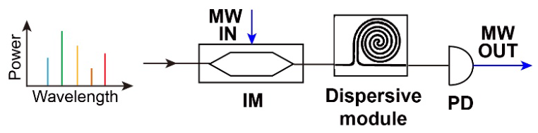
Figure 2.
The MWP low-pass filter based on the transversal filter system using a soliton crystal microcomb. (a) Experimental setup of the MWP low-pass filter. EDFA: erbium-doped fibre amplifier. MRR: microring resonator. IM: intensity modulator. SMF: single-mode fibre. PD: photodetector. VNA: vector network analyzer. (b) Optical spectrum of the soliton crystal microcomb. (c) Simulated and measured radiofrequency (RF) response of the low-pass filter.
Figure 2.
The MWP low-pass filter based on the transversal filter system using a soliton crystal microcomb. (a) Experimental setup of the MWP low-pass filter. EDFA: erbium-doped fibre amplifier. MRR: microring resonator. IM: intensity modulator. SMF: single-mode fibre. PD: photodetector. VNA: vector network analyzer. (b) Optical spectrum of the soliton crystal microcomb. (c) Simulated and measured radiofrequency (RF) response of the low-pass filter.
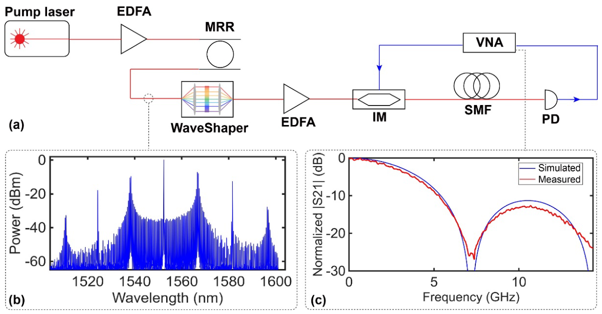
Figure 3.
Measured electrical spectra of the input and output microwave signals used for RF link gain and noise figure measurement. (a) Input microwave signal at 1 GHz with a power of ~2.68 dBm. (b) Output microwave signal at 1 GHz with a measured power of ~-2.48 dBm.
Figure 3.
Measured electrical spectra of the input and output microwave signals used for RF link gain and noise figure measurement. (a) Input microwave signal at 1 GHz with a power of ~2.68 dBm. (b) Output microwave signal at 1 GHz with a measured power of ~-2.48 dBm.
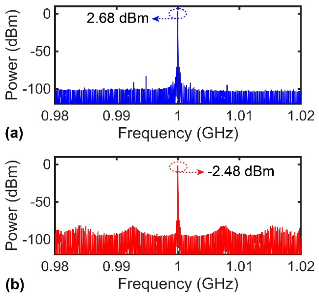
Figure 4.
Spurious-free dynamic range (SFDR) measurement. (a) Measured two-tone microwave output spectra at different input RF power ranging from ~-7.58 dBm to ~-0.25 dBm. IMD3: third-order intermodulation distortion. (b) Measured SFDR of the MWP low-pass filter.
Figure 4.
Spurious-free dynamic range (SFDR) measurement. (a) Measured two-tone microwave output spectra at different input RF power ranging from ~-7.58 dBm to ~-0.25 dBm. IMD3: third-order intermodulation distortion. (b) Measured SFDR of the MWP low-pass filter.
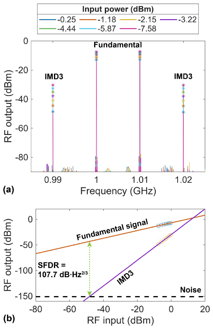
Figure 5.
Benchmarking of the key RF metrics for the reported MWP filters listed in Table 1, including RF link gain, noise figure, and SFDR. The box plots show upper and lower quartiles (25% and 75%), the median (50%), and the best as well as worst reported values. The RF metrics measured in this work are marked by purple stars.
Figure 5.
Benchmarking of the key RF metrics for the reported MWP filters listed in Table 1, including RF link gain, noise figure, and SFDR. The box plots show upper and lower quartiles (25% and 75%), the median (50%), and the best as well as worst reported values. The RF metrics measured in this work are marked by purple stars.
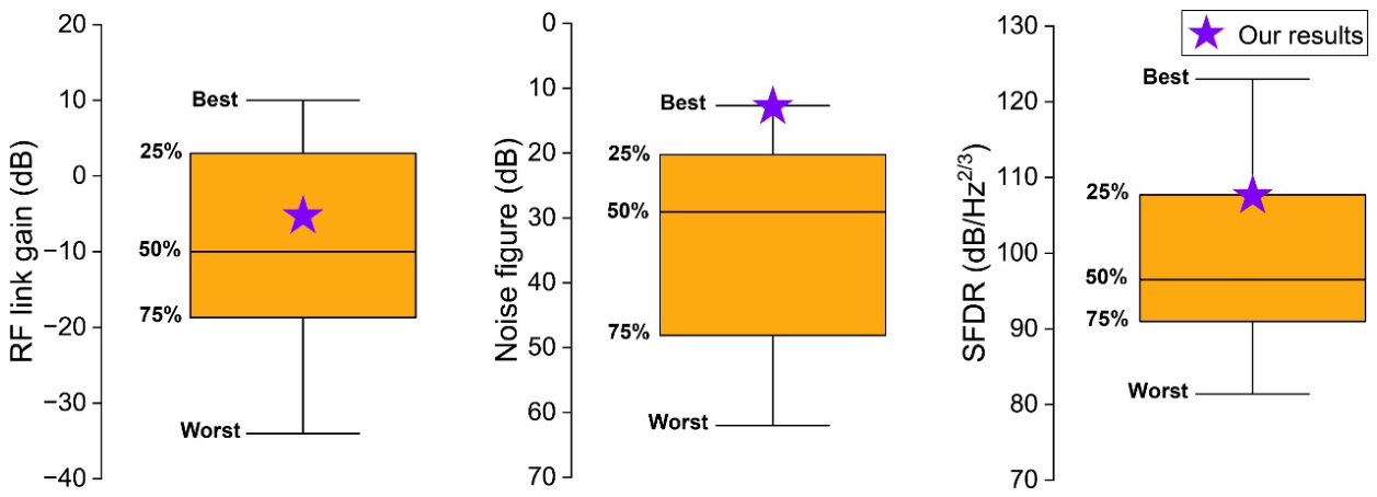

Table 1.
Comparison of key rf metrics for reported mwp filters.
| Mechanism | Filter type | RF link gain (dB) | Noise figure (dB) | SFDRa (dB/Hz2/3) | Ref. |
|---|---|---|---|---|---|
| Bragg-grating-based spectral filtering | Band-pass filter | -18.7 | 62 | 89.8 | [27] |
| Bragg-grating-based spectral filtering | Band-pass filter | -34 | − b | 95.8 | [28] |
| Microresonator-based spectral filtering | Notch filter | 3 | 31 | 100 | [29] |
| Microresonator-based spectral filtering | Band-pass filter | -10 | 45 | 105 | [30] |
| Microresonator-based spectral filtering | Band-pass filter | 8.97 | 33 | 88.93 | [31] |
| Microresonator-based spectral filtering | Notch filter | 8 | 15.6 | 116 | [32] |
| Microresonator-based spectral filtering | Band-pass filter | -10 | 27 | − | [33] |
| Stimulated Brillouin scattering | Notch filter | -10.1 | 27.1 | 96.5 | [34] |
| Microresonator-based spectral filtering Stimulated Brillouin scattering |
Notch filter | -8 | 20.8 | 92.2 | [35] |
| Ring-assisted interferometric filtering | Low-pass filter | -20 | − | 81.4 | [36] |
| Ring-assisted interferometric filtering | Band-pass filter Notch filter |
-28.2 | 51.2 | 99.7 | [37] |
| Ring-assisted interferometric filtering | Notch filter | 10 | 15 | 116 | [26] |
| Notch filter | -26 | 35 | 123 | ||
| Ring-assisted interferometric filtering | Band-pass filter Notch filter All-pass filter |
9 | 23 | 112 | [38] |
| Photonic-phononic emitter-receiver filtering | Band-pass filter | -17.3 | 56.7 | 90.3 | [39] |
| Photonic-phononic emitter-receiver filtering | Notch filter | -3.6 | 52.5 | 93.6 | [40] |
| Microcomb-based transversal filter system | Low-pass filter | -14.8 | 19.7 | 91 | Our work [17] |
| Microcomb-based transversal filter system | Low-pass filter | -5.16 | 12.32 | 107.7 | This work |
a. SFDR: spurious-free dynamic range; b. There is no reported value for this parameter in the literature.
Disclaimer/Publisher’s Note: The statements, opinions and data contained in all publications are solely those of the individual author(s) and contributor(s) and not of MDPI and/or the editor(s). MDPI and/or the editor(s) disclaim responsibility for any injury to people or property resulting from any ideas, methods, instructions or products referred to in the content. |
© 2026 by the authors. Licensee MDPI, Basel, Switzerland. This article is an open access article distributed under the terms and conditions of the Creative Commons Attribution (CC BY) license (http://creativecommons.org/licenses/by/4.0/).
Copyright: This open access article is published under a Creative Commons CC BY 4.0 license, which permit the free download, distribution, and reuse, provided that the author and preprint are cited in any reuse.


