

Submitted:
03 July 2026
Posted:
07 July 2026
You are already at the latest version
Abstract
Combining the advantages of nickel cobalt sulfide and layered double hydroxide ex-hibits great potentials in designing of high-performance electrode materials for super-capacitors. Here, a representative nickel cobalt sulfide/layered double hydroxide het-erostructure has been deposited on carbon cloth to construct free-standing electrode for supercapacitor, marked as NCS@NCOH/CC. Benefited from the nanoporous struc-ture and ultrathin nanosheets, especially the enhanced electronic transfer kinetics due to heterostructure design, the electrode presents potential capacitive performance. Specifically, when increasing the current density from 1 to 20 A g-1, the DSC declines from 1339.1 to 1149.9 F g-1, corresponding to a retention of 85.9%, manifesting excep-tional rate performance. When charging and discharging under 10 A g-1 for 10,000 cy-cles, the DSC can maintain 71.3%, illustrating good cycle durability. Moreover, the fabricated NCS@NCOH/CC//AC/NF hybrid capacitor also demonstrates unique cyclic stability of 86.9% energy retention after 10,000 cycles under 5 A g-1. And an energy density of 20.52 Wh kg-1 at 1604.2 W kg-1 can be realized, corresponding to a tenfold increase compared with AC/NF//AC/NF symmetric capacitor. This work proves the feasibility of fabricating high performance transition metal sulfide@ hydroxide hetero-structure electrode by an electrodeposition method.
Keywords:
nickel cobalt sulfide
; nickel cobalt layered double hydroxide
; heterostructure
; free-standing
; hybrid capacitor
1. Introduction
To alleviate the energy crisis caused by the depletion of fossil fuels, new rechargeable lithium-ion batteries, fuel cells and supercapacitors have attracted people’s interests in the last decades [1]. Among them, supercapacitors feature extremely high-power densities and ultralong cycle abilities, therefore, exhibit vastly promising develop potentials [2]. However, their limited energy densities, usually from several to dozens of Wh kg-1, have seriously limited their practical applications. Thus, to enhance the energy density by preparing high capacitance materials become a significant measure to promote the development of supercapacitors [3].
Presently, due to the high theoretical capacitance, transition metal oxides [4], sulfides [5,6,7] and double hydroxides [8,9] have become the mostly used positive materials for constructing high energy density supercapacitors, such as hybrid supercapacitors and asymmetric supercapacitors. Nevertheless, their inherent low conductivities compromise their rate and cyclic performance. Recently, to assembly heterostructures by coupling two of them have proven robust enhancement in high-rate charging-discharging and cycling capability [10,11,12]. In the heterostructure family, those composited by nickel cobalt sulfides (NCS) and nickel cobalt double hydroxides (NCOH) have been investigated intensively recently in view of their high capacitance, easy-to-fabrication and composition controllability [13,14,15]. In addition, for the preparation of NCS-NCOH heterostructures, compared with in-situ hydrothermal, electrodeposition exhibits particular advantages of simplicity, safety and energy savings, therefore, have fascinated much attentions recently [16,17]. In our very recent work, we have just explored the feasibility of electrodepositing NCS@NCOH on carbon cloth as a free-standing electrode for supercapacitor [18]. The results verified the improved rate and cyclic abilities of the heterostructure compared with the NCS and NCOH single electrodes. However, as known, the capacitive merits of NCOH are linked tightly to the molar ratio of nickel to cobalt [19], but, until now, there are no works focusing on regulating nickel cobalt molar ratio to optimize the electrochemical performance of NCS@NCOH heterostructures fabricated by an electrodeposition method. Moreover, the charge storage mechanism of NCS@NCOH based free-standing electrode has not been thoroughly studied yet in some recently reports, especially through in situ Raman technology [13,14,15,20,21].
Inspired by this, herein, a series of NCS@NxCyOH heterostructures with different nickel cobalt stoichiometric ratios have been fabricated on carbon cloth (CC) by a two-step electrodeposition route. Owing to the various roles of nickel and cobalt in electrochemical reaction and interface function, these NCS@NxCyOH/CC electrodes displayed distinct capacitive responses. Specifically, the NCS@NCOH/CC electrode (when x=y=1) delivered the optimal rate and cyclic performance, corresponding to a capacitance retention of 71.2% after 10000 cycles under 10 A g-1. Moreover, the hybrid supercapacitor (HC) comprised of NCS@NCOH/CC cathode and activated carbon (AC) also presented excellent cycling stability with 86.9% energy retention after 10000 cycles under 5 A g-1, and showed an energy density of 20.52 Wh kg-1 which was tenfold of that of AC//AC symmetric capacitor (2.61 Wh kg-1).
2. Materials and Methods
2.1. Materials
Nickel sulfate hexahydrate (NiSO4·7H2O, AR, 98%), cobalt sulfate heptahydrate (CoSO4·7H2O, AR, 99%) and potassium hydroxide (KOH, AR, 85%) were obtained from Shanghai Aladdin Biochemical Technology Co., Ltd, cobalt nitrate hexahydrate (Co(NO3)2·6H2O, AR, 98%) and alcohol dehydrated (C2H6O, 99.5%) were purchased from Guangdong Guanghua Sci-Tech Co., Ltd, thiourea (CH4N2S, AR, 99%), 1-methyl-2-pyrrolidinone(C5H9NO, AR, 99%), conductive carbon black (Super C45), and Kurary activated carbon YP-50 was purchased from Shanghai Macklin Biochemical Co., Ltd. Polyvinylidene fluoride (PVDF, AR, 99%) was obtained from Shanghai Yuanye Bio-Technology Co., Ltd. NF (300 mm×200 mm×0.3 mm) and CC (WOS1011) were obtained from Suzhou Keshenghe Metal Materials Co., Ltd. All chemicals are used without further treatment. All solutions were prepared with de-ionized water. Carbon cloth was soaked firstly, then washed by deionized water and ethanol dehydrated ultrasonically.
2.2. Electrodes Preparation
The NCS@NxCyOH/CC electrodes were assembled via a two-step potentiostatic electrodeposition process, as illustrated by Figure 1a. Firstly, NCS was electrodeposited on CC substrate in a three-electrode cell with CC (2 cm×1 cm), Pt plate and Ag/AgCl electrode as the working electrode (WE), counter electrode (CE) and reference electrode (RE), respectively. The electrolyte solution was composed of 0.005 mol L-1 NiSO4, 0.01 mol L-1 CoSO4 and 0.5 mol L-1 thiourea (TU). Secondly, NxCyOH were electrodeposited on the surface of NCS in the same electrolytic device as described above where the electrolytes were changed to NiSO4 and Co(NO3)2. For convenience, when the concentrations of NiSO4 and Co(NO3)2 were 0.005 and 0.01 mol L-1, 0.005 and 0.005 mol L-1, 0.005 and 0.0025 mol L-1, the products were labeled as NC2OH, NCOH, N2COH, respectively. All the electrodeposition processes were conducted on a portable electrochemical workstation (HY-1550-PLUS) under -1.0 V (vs. Ag/AgCl) at 25 ℃ for 15 min. The deposits were washed and dried before physical characterization and electrochemical measurements. The mass loadings were measured to be approximately 2.4, 1.0 and 1.1mg cm-2 for the NCS@NC2OH/CC, NCOH/CC and N2COH/CC electrodes, respectively, by an electronic analytical balance (SN-FA1004).
2.3. Assembly of Hybrid Supercapacitor
The HC was fabricated using the NCS@NCOH/CC electrode, activated carbon (AC) electrode, and 2 mol L-1 KOH as the cathode, anode and electrolyte solution, respectively, in a two-electrode cell. The AC electrode was prepared by mixing AC, polyvinylidene fluoride (PVDF), and super carbon black (SP) in a mass ratio of 8:1:1 under the assist of 1-methyl-2-pyrrolidinone (NMP). Then the slurry was painted on nickel foam (NF) and dried, finally, the anode was acquired by pressing NF under a powder tablet press. The weight proportion of cathode to anode was determined by formula (1) according to the charge balance equation.
In formula (1), symbols m, C, and V mean the active mass, discharge specific capacitance (DSC), and working potential window (WPW) of the electrodes, respectively, with the subscripts + and – representing the cathode and anode, respectively. The DSCs were calculated from CV curves according to formula (2) [22]:
where Cm, S, v, and m mean the DSCs, integrated area of CV curves, potential scan rates, potential windows and active mass of the electrodes, respectively.
2.4. Material Characterizations
The electrodes were characterized by X-ray diffraction (XRD, Ultima IV) with a Cu Kα radiation source (λ=1.54784 A(o)) under a scan rate of 20 ° min-1 between 10 and 80 °. The electrodes were observed by scanning electron microscopy (JSM-7610F) and transmission electron microscopy (TEM, FEI Talos f200s) under an accelerating potential of 200 kV in bright field. The element distribution was analyzed by energy dispersive spectrometer (EDS) at 12 kV. The element valences were analyzed by X-ray photoelectron spectroscopy (XPS, Thermofisher Nexsa) with Al kα radiation source. Functional groups of the electrodes were characterized by Fourier transform infrared spectroscopy (FTIR, Spirit-T). In situ electrochemical Raman spectrum was measured by Raman Spectrometer (Raman, Beijing Zhongyuan Huanke Technology Co., Ltd, DEEP-INRS-II) in a three-electrode cell with the NCS@NCOH/CC electrode, Pt, Hg/HgO electrode and 2 mol L-1 KOH as the WE, CE, RE and electrolyte solution, respectively. The test was conducted in a potential window of 0-0.5 V under a current density of 0.7 mA cm-2 for two charge-discharge cycles with an excitation wavelength of 623 nm. The scan range is 200-800 cm-1 and the scan potential interval is 0.05 V.
2.5. Electrochemical Measurements
All the electrochemical measurements of the NCS@NxCyOH/CC electrodes were performed within a three-electrode electrolytic cell using 2 mol L-1 KOH, Pt and Hg/HgO electrode as the electrolyte solution, CE and RE, respectively. The galvanostatic charge-discharge (GCD) tests were performed on a Land battery tester (CT3004A). The electrochemical impedance spectroscopy (EIS) and cyclic voltammetry (CV) were conducted on an electrochemical workstation (CHI604F). Detailly, the EIS was measured between a frequency range from 10-2 to 105 Hz under open circuit potential with an amplitude of 5 mV. The CV curves of the NCS@NxCyOH/CC electrodes were collected from 0 to 0.6 V (vs. Hg/HgO) under different scan rates from 5 to 100 mV s-1, the CV curves of AC electrode was tested from 0 to -1.0 V The SCs of the electrodes and HC were computed from the discharge curves based on formula (3) [23]:
where Cm is the SC (F g-1), I is the current density (A g-1), is the discharge time (s) and is the potential window. The energy density (E, Wh kg-1) and power density (P, W kg-1) of HC were calculated by equations (4) and (5) [24]:
where (F g-1), (V) and (s) are the SC, potential window and discharge time of the device, respectively. And the can be obtained according to equation (3).
3. Results
3.1. Assembly of Electrode
Figure 1a depicts the preparation of NCS@NxCyOH/CC electrodes. As shown, NCS core layer was firstly deposited on carbon fiber surface under electric field, the underling reaction mechanism can be found in our previous work [7]. Then NxCyOH shell layers could in situ deposit on the surface of NCS, by tunning the molar ratio of Ni to Co within the electrolyte solutions, NC2OH, NCOH and N2COH can be obtained when n(Ni): n(Co)=1:2, n(Ni): n(Co)=1:1 and n(Ni): n(Co)=2:1, respectively. In these core-shell heterostructures, carbon fibers serve as the electronic conductor and skeleton, NCS acts as high conductive interlayer which can promote electron transportation to NxCyOH layer, while NxCyOH outer layers can provide plentiful surfaces for interfacial faradic reaction. Very importantly, the CC@NCS and NCS@NxCyOH heterointerfaces can further enhance the electronic migration through internal electric field, favorable for Faradic reactions [20,25,26].
3.2. Material Characterization
Figure 1b shows the XRD patterns of the NCS@NxCyOH/CC electrodes along with CC substrate. As shown, by comparison, all the patterns display analogous shape with two broad diffraction peaks, which should be the characteristic peaks of CC. No other peaks can be observed, suggesting the poor crystallinities of as prepared NCS@NxCyOH [7]. Thus, to characterize the chemical composition of these deposits, FTIR were also measured and the results are supplied in Figure 1c-d. As seen, those weak absorption peaks located at 3554 and 1636 cm-1 should correspond to the stretching and bending vibration of O-H in the adsorbed water [5], the peak at 2904 cm-1 should belong to the stretching vibration of C-H bond that related to CC [6], the one situated at 1110 cm-1 should be assigned to SO42- intercalated into NCOH. While those observed in the fingerprint region should be related to the metal-oxygen and metal-sulfur binds, such as Co-S (526 cm-1), Ni-O (484 cm-1), Ni-S (455 cm-1) and Co-O (438 cm-1, 424 cm-1) [8]. Therefore, the NCS@NxCyOH heterostructures should be made up of nickel cobalt sulfides, nickel cobalt oxides, nickel cobalt hydroxides, intercalated SO42- and absorbed H2O.
To further analyze the elemental chemical valences of NCS@NCOH/CC electrode, XPS spectra of the electrode are also provided in Figure 2. From the survey spectrum (Figure 2a), characteristic peaks of Ni2p, Co2p, O1s, C1s and S2p can be identified, suggesting the coexistence of Ni, Co, O, C and S. In Figure 2b, the high-resolution spectrum of Ni2p can be fitted into six peaks by Gaussian-Lorentzian method, those lie in 855.1 and 872.9 eV belong to the 2p3/2 and 2p1/2 spin orbitals of Ni2+, while those located at 856.5 and 874.6 eV correspond to the 2p3/2 and 2p1/2 spin orbitals of Ni3+, and those located at 783.3 and 802.8 eV belong to the satellite peaks [27]. In a similar way, the spectrum of Co2p as seen in Figure 2c, can also be divided into six peaks, namely, those situated at 780.1 and 796.5 eV can be indexed to the 2p3/2 and 2p1/2 spin orbitals of Co3+, and those at 781.5 and 797.9 eV correlate to the 2p3/2 and 2p1/2 spin orbitals of Co2+, while the other peaks belong to the satellite peaks [28,29]. As shown in Figure 2d, the high-resolution O1s spectrum can be split into five peaks which can be assigned to O-Ni (530.2 eV), O-Co (530.9 eV), O-H (531.5 eV),O=C (532.2 eV) and H2O, respectively, verifying the form of NCOH [30]. The S2p spectrum, as seen in Figure 2e, can be separated into three peaks, those located at 163.3 and 164.5 eV should correspond to the 2p3/2 and 2p1/2 spin orbitals of S2-, while the one at 168.7 eV belongs to SO42- [31]. Finally, the C1s spectrum (Figure 2f) can be decomposed into four peaks as well, corresponding to C-C sp2 (284.1 eV) and sp3 (284.8 eV) hybrid orbitals, C-O (286.1 eV) and C=O (287.8 eV) groups [32]. These results can indicate the NCS@NCOH/CC electrode consists of NCS and NCOH with SO42-.
Figure 3 exhibits the SEM images of the NCS@NxCyOH/CC electrode. As shown, in all the electrodes, carbon fibers are covered tightly by NCS@NxCyOH nanoflakes, manifesting robust structural stability. The open nanopores and ultrathin sheets can ensure the easy accessibility of electrolyte solution and fast ionic migration in active material, which is helpful for the fast charging and discharging under high current densities [33]. From the micromorphology, it is difficult to judge the superiorities of these electrodes. Besides, for comparison, the SEM images of the NCS/CC and NCOH/CC electrodes are supplemented in Figure S1, in which, similar nanosheets can be observed too. Furthermore, the EDS results in Figure S2 indicate that the molar ratios of Ni to Co are 21.9:23.1, 25.6:20.4 and 17.1:23.6 for the NCS@NC2OH/CC, NCS@NCOH/CC and NCS@N2COH/CC electrodes, respectively. And the S element in NCS@NCOH cannot be calculated because of its trace amount. The low sulfur contents in these electrodes may be related to the coverage of NxCyOH.
To clearly observe the microstructure and element distribution of NCS@NCOH nanoflakes, TEM HRTEM and EDX images of NCS@NCOH are provided in Figure 4. As seen in Figure 4a, the deposit presents ultrathin nanoflake morphology which is consistent with the SEM image in Figure 3b. In the HRTEM image as shown in Figure 4b, some poor lattice fringes can be observed locally, indicating the low crystallinity of the nanosheet, which is coincide with the XRD analysis. To identify the phase of the nanosheet, the inverse FFT images of the areas masked by the yellow and green rectangles are shown in Figure 4c and Figure 4d. As seen, in the yellow area, a crystal lattice spacing of 0.20 nm can be measured, corresponding to the (107) plane of (Ni6.10Co2.90)(OH)18.27(CO3)1.315·6.7H2O (PDF#33-0429), analogously, in the green area, the lattice interlayer spacing is 0.23 nm, assigned to the (015) crystal plane of (Ni6.10Co2.90)(OH)18.27(CO3)1.315·6.7H2O [33]. However, evident interlayer dislocations can be clearly observed in Figure 4d, demonstrating the intercalations of SO42- and/or H2O molecules, which is favorable for the ionic transportation in NCOH nanosheet [19,34]. In addition, the EDX mappings of NCS@NCOH nanoflake as shown in Figure 4e demonstrates the homogenous distributions of Ni, Co, O, and S during electrodeposition. The weak signal of S element further confirms the above-mentioned EDS analysis, which may be due to the signal of NCS can be concealed by the NxCyOH layers.
3.3. Electrochemical Evaluations
For electrochemical performance analysis, CV curves of the NCS@NxCyOH/CC electrodes are exhibited in Figure 5a. As shown, for all the electrodes, one couple of redox peaks can be observed, indicating their battery-type behaviors which feature bulk redox charge storage mechanism [35,36]. Specifically, the oxidation peaks locate at 0.402, 0.465, and 0.505 V, respectively, for the NCS@NC2OH/CC, NCS@NCOH/CC, and NCS@N2COH/CC electrodes. And the reduction peaks situate at 0.076, 0.117, and 0.152 V, respectively, corresponding to peak potential gaps of 0.326, 0.343, and 0.0.353 V. Therefore, the NCS@NC2OH/CC electrode exhibits the best reversibility [37]. The underlying charge storage mechanism can be expressed as reactions (6)-(9):
NiS+ OH-↔NiSOH+ e-
CoS+ OH-↔CoSOH+ e-
Ni (OH)2+OH-↔NiOOH+H2O+e-
Co (OH)2+OH-↔CoOOH+H2O+e-
In addition, the CV curves of the NCS@NCOH/CC electrode under different scan rates are also provided in Figure S3. As shown, when increasing the scan rate from 5 to 100 mV s-1, the oxidation peaks move to higher potentials, with the reduction peaks moving to lower potential, indicating serious polarization. Figure 5b shows the initial discharge profiles of these electrodes under 1 A g-1 in a PW of 0.5 V. It is evident that the NCS@NCOH/CC electrode delivers moderate DSC, slightly lower than that of the NCS@N2COH/CC electrode. Besides, for the NCS@NCOH/CC electrode, its initial discharge profiles under different current densities have also been provided in Figure 5c. The DSCs calculated based on these profiles are 1339.1, 1317.9, 1305.4, 1291.8, 1259.4, 1149.9 and 639.2 F g-1 under 1, 2, 3, 5, 10, 20, and 50 A g-1, respectively. For comparison, the DSCs of the NCS@NxCyOH/CC electrodes are plotted in Figure 5d and listed in Table S1. As shown, the NCS@NCOH/CC electrode presents a retention rate of 85.9% when increase the current density from 1 to 20 A g-1, much higher than those of NCS@NC2OH/CC (68.4%) and NCS@N2COH/CC (72.2%) electrodes. Even under 50 A g-1, a DSC of 639.2 F g-1 can still be reserved, corresponding a retention ratio of 47.7%. The results can be challengeable to some recent reported NCS and NCOH materials, as illustrated in Table S3. Moreover, the cyclic performance of these electrodes is also compared in Figure 5e. As seen, when successively charging-discharging under 10 A g-1 for 10,000 cycles, the NCS@NCOH/CC electrode can demonstrate a capacitance retention of 71.3%, higher than that of the NCS@N2COH/CC electrode (60.1%), slightly lower than that of the NCS@NC2OH/CC electrode (72.5%). For comparison, Figure S4 supplements the electrochemical performance of the NCS/CC and NCOH/CC electrodes. As shown, the NCS/CC electrode possesses better rate and cyclic stability than the NCS@NxCyOH/CC and NCOH/CC electrodes, but compromised DSC. In conclusion, the NCS@NCOH/CC electrode exhibits the optimum comprehensive capacitive performance, which should be attributed to its more uniform nanopores, heterointerface synergistic effect and moderate molar ratio of nickel to cobalt.
To interpret the good rate and cyclic performance of the NCS@NCOH/CC electrode, the electrode process kinetics of the NCS@NxCyOH/CC electrodes were investigated by electrochemical impedance spectra (EIS) technique. The obtained Nyquist plots are displayed in Figure 5f. Typically, all the plots are made up of three sectors, namely, an intercept in the high frequency region, a compressed semicircle in the middle frequency region and a slash in the low frequency. As known, the physical significance of the high frequency intercept of Z′ axis is the series impedance of the electrolyte solution, conducting wire and their connect points, represented by R1 as seen in the embedded equivalent electric circuit (EEC). The diameter of the semicircle indicates the charge transfer impedance labeled as R2, which is immediately linked to the interfacial redox reaction. While the slash characterizes the difficulty of ion diffusion in active materials, usually named as Warburg impedance and expressed as W1 [16]. Besides, the experimental data were fitted based the EEC in Figure 5f and the fitting parameters are supplemented in Table S2. As seen, the values of R1 and R2 of the NCS@NCOH/CC electrode are 1.489 and 0.09 Ω,lower than those of the NCS@NC2OH/CC (1.374 and 0.25 Ω) and NCS@N2COH/CC (2.738 and 0.28 Ω) electrodes, exhibits excellent electrode kinetics, helpful for the large current charge and discharge.
To investigate the practical application capability of the NCS@NCOH/CC electrode, a hybrid capacitor (HC) NCS@NCOH/CC//AC/NF was fabricated, and its electrochemical performance was studied. Figure 6a gives the CV curves of the NCS@NCOH/CC cathode and AC anode to determine the potential window of HC and the mass ratio of cathode to anode. In the picture, a rectangular CV loop of AC anode and peak shape CV loop of cathode can be observed. Moreover, the DSCs of them can be calculated based on equation (2), which are 80.4 and 1027.5 F g-1. Therefore, the theoretical mass ration of m+ to m- can be determined to be about 1: 7.69. However, the practical value in our HC is 1:5.04. For comparison, an asymmetric capacitor AC/NF//AC/NF was also fabricated under the same condition, in which the mass ratio is 6.48:6.88. From the CV contour, a potential window of 1.6 V can be rational. Figure 6b shows the CV contours of HC at various scan rates from 10 to 200 mV s-1 in a potential window of 1.6 V. As seen, these CV curves exhibit a quasi-rectangular shape, similar to that of AC//AC device (Figure S6a). Under low scan rates, such as 10 mV s-1, evident oxygen evolution phenomenon can be observed, demonstrating the high catalytic activity towards to oxygen evolution reaction of NCS@NCOH heterostructure. However, high scan rate can effectively inhibit this side rection as seen in Figure 6b. Analogous question can be found in the GCD profiles as shown in Figure 6c. Detailly, when charging under 2, 3, and 5 A g-1, an obvious oxygen evolution potential plateau can be observed, but it disappears under 10 A g-1. The reason of this is related to the increased overpotential of oxygen evolution under high current densities. As exhibited in Figure 6d, the DSCs of the HC are 57.2, 57.2, 53.5, and 41.7 F g-1 under 2, 3, 5, and 10 A g-1, respectively, (Particularly, the current density for HC is calculated based the total mass of cathode and anode.), exhibiting good rate performance. More significantly, the cyclic stability of the HC was tested under 5 A g-1 (30.2 A g-1 vs. NCS@NCOH/CC) and the results are exhibited in Figure 6e. As seen, after 10,000 cycles, the energy density of the HC can keep 86.9%, demonstrating excellent cyclic stability, approaching or surpassing some recently reported NCS and NCOH related materials (Table S4). The coulombic efficiency of the HC undergoes a gradual increase in the initial stage, which should be caused by oxygen evolution, then goes into a steady state of nearly 100%. Figure 6f supplies the Ragone plots of the NCS@NCOH/CC//AC/NF and AC/NF//AC/NF devices. As shown, for the former, a maximum energy density of 20.52 Wh kg-1 can be acquired under a power density of 1604.2 W kg-1, largely exceeding that of AC/NF//AC/NF (2.63 Wh kg-1 at 526.9 W kg-1). When increase the power density to 6760.2 W kg-1, the energy density can retain 12.45 Wh kg-1. The relative low energy density of our HC should be caused by the low capacitance of AC anode. While the enhanced cyclic performance the NCS@NCOH/CC//AC/NF HC should also be attributed to the unique cyclic performance of AC anode (Figure S5). Additionally, the CV curves, GCD profiles, rate and cyclic performance are further supplemented in Figure S5 for comparison study. The Nyquist plots of the HC are provided in Figure S7. As seen, the small charge transfer impedance and large slope of low frequency slash indicate good electrode process kinetics, which favors the excellent rate and cyclic performance of the HC. In the end, the NCS@NCOH/CC electrode exhibit considerable application prospects.
3.4. In Situ Raman Analysis
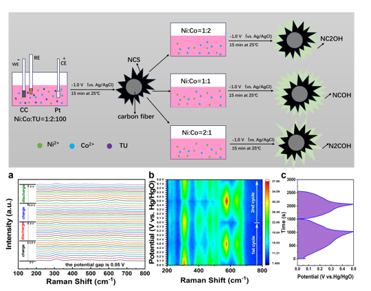
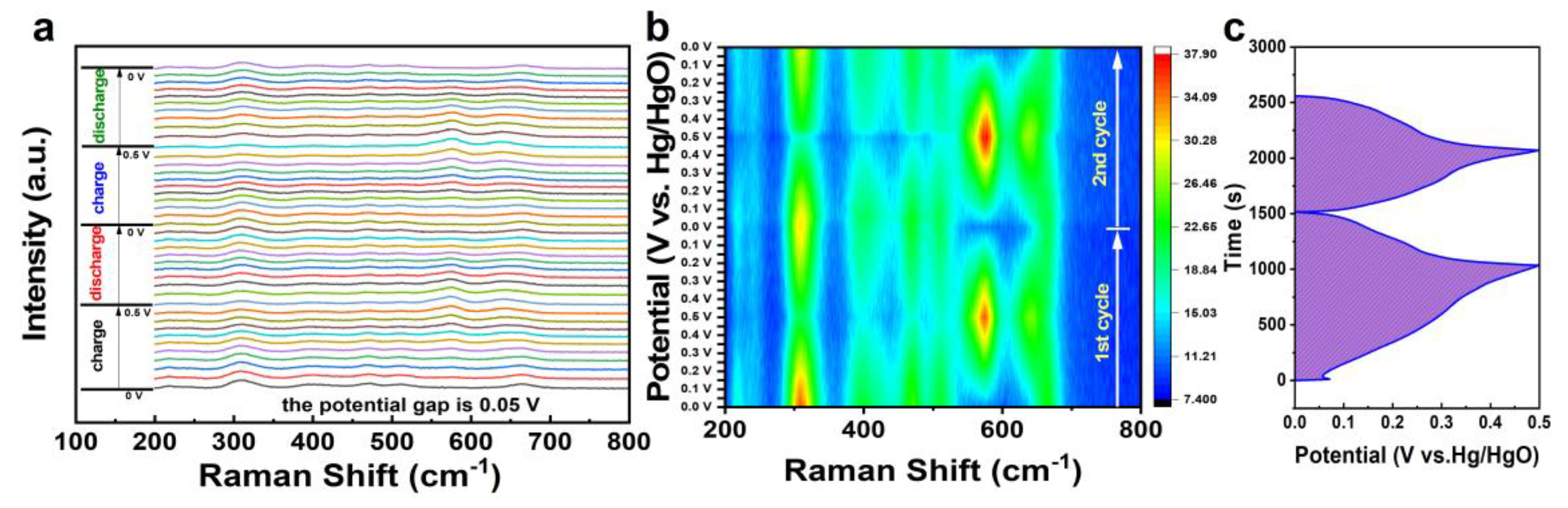
For deep explore the charge storage mechanism of the NCS@NCOH/CC electrode, in situ electrochemical Raman spectra during the first and second charge-discharge cycles are provided in Figure 7a-b. The corresponding GCD profiles are shown in Figure 7c. As seen, before charging, when the potential is 0 V, six Raman peaks can be clearly observed. Specifically, the peaks emerged at 218.9, 309.6, 400.4, 472.1, 511.2, and 663.8 cm-1 should be assigned to Ni-S (F2g), Co-S(F2g), CoS (E2g), Ni-O(E2g), Co-O (E2g), and Co-O (A1g) bonds, further confirming the successful preparation of NCS and NCOH composite [32,38,39,40,41]. It is remarkable that during the charging from 0.0 to 0.5 V, the intensities of decline gradually, proving the structural changes, which should be in line with reactions (6)-(9). More importantly, two new peaks formed at 573.4 and 640.5 cm-1 can be seen when the potential reaches 0.1 V, then tends to maximum at 0.5 V, during discharging, they then gradually disappear. Therefore, it can be deduced that these two peaks should belong to CoSOH and NiSOH, respectively, according to their intensities. Upon discharging, the intensities of these peaks cannot completely recover to initial states, indicating the irreversibility of these Faradic reactions. Additionally, after two charging-discharging cycles, the intensities of Ni-S and Co-S bonds (218.9 and 309.6 cm-1) evidently decline, which should be due to the removal of S element during cycling as demonstrated in our last work [18]. Based on these observations, the limited cyclic capability of the NCS@NCOH/CC electrode should be related to the irreversibility of charge storage reactions owing to the removal of S element during charging-discharging.
4. Conclusions
In summary, a group of NCS@NxCyOH/CC binder-free electrodes have been fabricated by a two-step electrodeposition approach. The results verify that molar ratio of nickel to cobalt in the outer layer can influence largely the capacitive properties of these electrodes. When switching the n(Ni): n(Co) to 1:1, the obtained electrode NCS@NCOH/CC electrode displayed the best comprehensive capacitive performance, namely, a DSC value of 1339.1 F g-1 can be acquired under 1 A g-1, which can keep 639.2 F g-1 under 50 A g-1. When charging discharging under 10 A g-1 for 10,000 cycles, 71.3 % of initial DSC can be retained. What’s more, a HC of NCS@NCOH/CC//AC/NF has been assembled, which exhibited excellent cyclic durability with 86.9% retention upon 10,000 cycles under 5 A g-1. Besides, an energy density of 20.52 Wh kg-1 can be accomplished under a power density of 1604.2 W kg-1. Finally, in situ Raman spectra verify that the irreversible structural evolution originated from sulfur loss results in the compromised cycling performance of the NCS@NCOH/CC electrode.
Supplementary Materials
The following supporting information can be downloaded at the website of this paper posted on Preprints.org, Figure S1: Sem images of the NCS/CC (a1-a2) and NCOH/CC (b1-b2) electrodes; Figure S2:EDS results of the NCS@NC2OH/CC (a, b), NCS@NCOH/CC (c, d) and NCS@N2COH/CC (e, f) electrodes; Figure S3: CV curves of the NCS@NCOH/CC electrode at different scan rates of 5-100 mV s-1; Figure S4: (a) CV curves at 10 mV s-1, (b) initial discharge curves under 1 A g-1, (c) rate performance, (d) cyclic performance under 10 A g-1 of the NCS/CC and NCOH/CC electrodes; Figure S5: Cyclic performance of the AC/NF anode under 5 A g-1; Figure S6: (a) CV curves under different scan rates from 10 to 200 mV s-1, (b) GCD profiles under different current densities from 1 to 5 A g-1, (c) rate performance, (d) cyclic performance of the AC/NF//AC/NF symmetric capacitor; Figure S7: Nyquist plot of the NCS@NCOH/CC//AC HC. The inset is the magnified plot and equivalent electric circuit for fitting; Table S1: DSCs of the NCS@NxCyOH/CC, NCS/CC, and NCOH/CC electrodes under different current densities; Table S2: Fitting parameters of Nyquist plots of the NCS@NxCyOH/CC electrodes based on the equivalent electric circuit in Figure 5f; Table S3: Comparison of the rate performance of the NCS@NCOH/CC with some recently reported NCS and NCOH related free-standing electrodes prepared by various techniques; Table S4: Comparison of the cyclic performance of the NCS@NCOH/CC//AC/NF hybrid capacitor with some recently reported NCS and NCOH related hybrid capacitors.
Author Contributions
Conceptualization, Y.W.; methodology, S.L. and L.G; software, Q.X.; validation, S.L., L.G. and L.L.; formal analysis, L.L.; investigation, S.L. and L.G; resources, Q.X.; data curation, S.L.; writing—original draft preparation, S.L. and Y.W.; writing—review and editing, Y.W.; visualization, Q.X.; supervision, L.L. and Y.W.; project administration, L.L.; funding acquisition, Y.W. and Q.X. All authors have read and agreed to the published version of the manuscript.
Funding
This research was funded by Natural Science Foundation of Guangxi Province (2025GXNSFAA069670), Guangxi Science and Technology Program (GUIKE XT2601570006), the Project Sponsored by the Scientific Research Fund for Doctor of Hezhou University (2024BSQD15).
Data Availability Statement
The original contributions presented in this study are included in the article/Supplementary Materials. Further inquiries can be directed to the corresponding author.
Acknowledgments
We also thank the Chengdu Phadcalc Technology Co., Ltd for the XPS, TEM, and in situ Raman examinations.
Conflicts of Interest
The authors declare that they have no known competing financial interests or personal relationships that could have appeared to influence the work reported in this paper.
References
- Simon, P.; Gogotsi, Y.; Dunn, B. Where Do Batteries End and Supercapacitors Begin? Science 2014, 343, 1210. [Google Scholar] [CrossRef] [PubMed]
- Simon, P.; Gogotsi, Y. Materials for electrochemical capacitors. Nat. Mater. 2008, 7, 845. [Google Scholar] [CrossRef] [PubMed]
- Zuo, W.; Li, R.; Zhou, C.; Li, Y.; Xia, J.; Liu, J. Battery-Supercapacitor Hybrid Devices: Recent Progress and Future Prospects. Adv. Sci. 2017, 4, 1600539. [Google Scholar] [CrossRef]
- Wei, S.; Wan, C.; Zhang, L.; Liu, X.; Tian, W.; Su, J.; Cheng, W.; Wu, Y. N-doped and oxygen vacancy-rich NiCo2O4 nanograss for supercapacitor electrode. Chem. Eng. J. 2022, 429, 132242. [Google Scholar] [CrossRef]
- Wang, Y.; Liao, L.; Yin, Z.; Wang, Z. Boosting the charge storage capability of NiCo2(OH)6-2xSx by sulfur modulation towards high performance binder-free electrode for hybrid supercapacitor. Mater. Chem. Phys. 2025, 334, 130470. [Google Scholar] [CrossRef]
- Xie, F.; Zhu, H.; Qu, Y.; Hu, J.; Tan, H.; Wang, K.; Sun, L. Promoted OH- adsorption and electron-transfer kinetics by electrospinning mono-disperse NiCo2S4 nanocrystals within porous CNFs for solid asymmetric supercapacitors. J. Colloid Interface Sci. 2024, 657, 63. [Google Scholar] [CrossRef] [PubMed]
- Wang, Y.; Liao, L.; Xie, Q.; Yin, Z. In situ growth of nickel cobalt sulfide on carbon cloth by electrodeposition as binder-free electrode for supercapacitor. Solid State Sci. 2025, 165, 107941. [Google Scholar] [CrossRef]
- Wang, Y.; Yin, Z.; Wang, Z.; Guo, H. Fabrication of NiCo Layered Double Hydroxide on Carbon Fiber Paper as High Performance Binder-free Electrode for Supercapacitors. Mater. Res. Bull. 2023, 167, 112408. [Google Scholar] [CrossRef]
- Song, Z.; Zhao, J.; Ghani, U.; Liu, W.; Ye, B.; Cai, X. Metal Organic Frameworks Derived Layered Double Hydroxide Nanosheets for Electrochemical Energy Storage and Conversion. ChemElectroChem 2024, e202300731. [Google Scholar]
- Wang, Y.; Yin, Z.; Wang, Z.; Li, X.; Guo, H.; Wang, J.; Zhang, D. Facile construction of Co(OH)2@Ni(OH)2 core-shell nanosheets on nickel foam as three dimensional free-standing electrode for supercapacitors. Electrochim. Acta 2019, 293, 40. [Google Scholar] [CrossRef]
- Zhang, J.; Gao, H.; Zhang, M. Y.; Yang, Q.; Chuo, H. X. NiCo2S4/Ni(OH)2 core-shell heterostructured nanotube arrays on carbon-fabric as high-performance pseudocapacitor electrodes. Appl. Surf. Sci. 2015, 349, 870. [Google Scholar] [CrossRef]
- Yao, P.; Li, Z.; Zhu, J.; Ran, X.; Shi, Z.; Zhu, J. Controllable synthesis of NiCo-LDH/Co(OH)2@PPY composite via electrodeposition at high deposition voltages for high-performance supercapacitors. J. Alloys Compd. 2021, 875, 160042. [Google Scholar] [CrossRef]
- Dai, Y.; Jiang, Y.; Wang, Q.; Dai, J. One-step preparation of NiCo2S4@NiCo-LDH nano-array structures for high-performance supercapacitor electrodes. New J. Chem. 2024, 48, 6809. [Google Scholar] [CrossRef]
- Zhou, Z.; Tie, J.; Yang, H.; Cheng, G.; Sun, M.; Yu, L. 3D hierarchical NiCo2S4/Ni–Co LDH architecture for high-performance supercapacitor. J. Mater. Sci.-Mater. El. 2021, 32, 3843. [Google Scholar] [CrossRef]
- Gu, Y.; Du, B.; Bai, Y.; Yang, L.; Wang, Y.; Li, X.; Liu, X. High-performance asymmetric supercapacitor electrode materials NiCo2S4@NiCo-LDH@Ni foam. Ionics 2024, 30, 6405. [Google Scholar] [CrossRef]
- Wang, Y.; Yin, Z.; Li, X.; Guo, H.; Zhang, D.; Wang, Z. Smartly tailored Co(OH)2-Ni(OH)2 heterostucture on nickel foam as binder-free electrode for high-energy hybrid capacitors. Electrochim. Acta 2019, 309, 140. [Google Scholar] [CrossRef]
- Nguyen, T.; Boudard, M.; Carmezim, M. J.; Montemor, M. F. Layered Ni(OH)2-Co(OH)2 films prepared by electrodeposition as charge storage electrodes for hybrid supercapacitors. Sci. Rep. 2017, 7, 39980. [Google Scholar] [CrossRef] [PubMed]
- Wang, Y.; Su, G.; Lin, S.; Xie, Q.; Chen, Z.; Liao, L. In situ electrodeposition of nickel cobalt sulfide/double hydroxide heterostructure on carbon cloth as a binder-free electrode for supercapacitors. Mater. Today Commun. 2026, 53, 115305. [Google Scholar] [CrossRef]
- Shah, S. S.; Aziz, M. A.; Ogawa, T.; Zada, L.; Marwat, M. A.; Abdullah, S. M.; Khan, A. J.; Usman, M.; Khan, I.; Said, Z.; Oyama, M. Revolutionary NiCo layered double hydroxide electrodes: Advances, challenges, and future prospects for high-performance supercapacitors. Mater. Sci. Eng. R Rep. 2025, 166, 101041. [Google Scholar] [CrossRef]
- Huang, J.; Yao, Y.; Ma, Y.; Gao, L.; Wang, Y.; Jia, L.; Xiao, W. NiCo-OH Nanosheets Coated with NiCoS Nanosheets for Supercapacitors and Alkaline Zinc Batteries. ACS Appl. Nano Mater. 2024, 20 7, 15035. [Google Scholar] [CrossRef]
- Xiao, L.; Tian, F.; Hu, Z.; Wang, Z.; Wang, S. Interfacial Electronic Engineering in NiCo2S4@NiAl-LDH Core-Shell Nanoarrays for Advanced Supercapacitor Electrodes. Chem. Asian J. 2026, 21, e70800. [Google Scholar] [CrossRef] [PubMed]
- Wang, Y.; Yin, Z. L.; Wang, Z. X.; Li, X. H.; Guo, H. J.; Wang, J. X.; Zhang, D. C. Facile construction of Co(OH)2@Ni(OH)2 core-shell nanosheets on nickel foam as three dimensional free-standing electrode for supercapacitors. Electrochim. Acta 2019, 293, 40. [Google Scholar] [CrossRef]
- Zhao, B. T.; Chen, D. C.; Xiong, X. H.; Song, B.; Hu, R. Z.; Zhang, Q. B.; Rainwater, B. H.; Waller, G. H.; Zhen, D. X.; Ding, Y.; Chen, Y.; Qu, C.; Dang, D.; Wong, C. P.; Liu, M. A high-energy, long cycle-life hybrid supercapacitor based on graphene composite electrodes. Energy Storage Mater. 2017, 7, 32. [Google Scholar] [CrossRef]
- Bai, X.; Liu, Q.; Zhang, H. S.; Liu, J. Y.; Li, Z. S.; Jing, X. Y.; Yuan, Y.; Liu, L. H.; Wang, J. Nickel-Cobalt Layered Double Hydroxide Nanowires on Three Dimensional Graphene Nickel Foam for High Performance Asymmetric Supercapacitors. Electrochim. Acta 2016, 215, 492. [Google Scholar] [CrossRef]
- Tangaemsakul, N.; Kannan, A.; Tantavichet, N. NiCoS/carbon black based bifunctional air electrode for Zn-air secondary batteries. J. Alloys Compd. 2021, 873, 159749. [Google Scholar] [CrossRef]
- Zhang, Y.; Li, Z.; He, S.; Qiao, Y.; Yuan, A.; Wu, J.; Zhou, H. Interfacial engineering of heterostructured CoP/FeP nanoflakes as bifunctional electrocatalyts toward alkaline water splitting. J. Colloid Interface Sci. 2025, 679, 20. [Google Scholar] [CrossRef] [PubMed]
- Xiao, J.; Tong, H.; Jin, F.; Gong, D.; Chen, X.; Wu, Y.; Zhou, Y.; Shen, L.; Zhang, X. Heterostructure NiS2/NiCo2S4 nanosheets array on carbon nanotubes sponge electrode with high specific capacitance for supercapacitors. J. Power Sources 2022, 518, 230763. [Google Scholar] [CrossRef]
- Zhu, M.; Lu, C.; Ma, Y.; Yang, Y. NiCo-glycolate-derived porous spherical NiCo2S4 for high-performance asymmetric supercapacitors. Appl. Organomet. Chem. 2023, 37, e7301. [Google Scholar]
- Qiang, S.; Li, Z.; He, S.; Zhou, H.; Zhang, Y.; Cao, X.; Yuan, A.; Zou, J.; Wu, J.; Qiao, Y. Modulating electronic structure of CoS2 nanorods by Fe doping for efficient electrocatalytic overall water splitting. Nano Energ. 2025, 134, 110564. [Google Scholar] [CrossRef]
- Zhang, Y.; Chen, Y.; Liang, K.; Zhang, Y.; Wang, D.; Wang, W.; Wang, J.; Du, X.; Mitsuzaki, N.; Chen, Z. NiCo layered double hydroxide/biomass-derived porous carbon aerogel composite for high-performance hybrid supercapacitors. J. Energy Storage 2024, 91, 112167. [Google Scholar] [CrossRef]
- Wang, J.; Wang, Z.; Liu, N.; Liu, C.; Yan, J.; Li, C. C.; Cui, J.; Liu, J.; Hu, X.; Wu, Y. Al doped Ni-Co layered double hydroxides with surface-sulphuration for highly stable flexible supercapacitors. J. Colloid Interface Sci. 2022, 615, 173. [Google Scholar] [CrossRef] [PubMed]
- Liu, M.; Farhadi, B.; Li, W.; An, L.; Li, Y.; Zou, Z.; Cong, Z.; Zhai, S.; An, Q.; Wang, K.; Tong, Y. Nickel-cobalt layer double hydroxide @ lignin-based hollow carbon quasi core-shell structure for high-performance supercapacitors. Electrochim. Acta 2024, 478, 143836. [Google Scholar] [CrossRef]
- Zhang, S.; Zhao, Y.; Gao, S.; Liu, C.; Chen, X. Design and synthesis of nickel-cobalt-aluminum hydroxide battery electrode materials for high-performance hybrid supercapacitors. J. Power Sources 2025, 632, 236370. [Google Scholar] [CrossRef]
- Hall, D. S.; Lockwood, D. J.; Bock, C.; MacDougall, B. R. Nickel hydroxides and related materials: a review of their structures, synthesis and properties. Proc. Math. Phys. Eng. Sci. 2015, 471, 20140792. [Google Scholar] [CrossRef] [PubMed]
- Augustyn, V.; Simon, P.; Dunn, B. Pseudocapacitive oxide materials for high-rate electrochemical energy storage. Energy Environ. Sci. 2014, 7, 1597. [Google Scholar] [CrossRef]
- Brousse, T.; Bélanger, D.; Long, J. W. To Be or Not To Be Pseudocapacitive? J. Electrochem. Soc. 2015, 162, A5185. [Google Scholar] [CrossRef]
- Conway, B. E.; Birss, V.; Wojtowicz, J. The role and utilization of pseudocapacitance for energy storage by supercapacitors. J. Power Sources 1997, 66, 1. [Google Scholar] [CrossRef]
- Wen, Y.; Peng, S.; Wang, Z.; Hao, J.; Qin, T.; Lu, S.; Zhang, J.; He, D.; Fan, X.; Cao, G. Facile synthesis of ultrathin NiCo2S4 nano-petals inspired by blooming buds for high-performance supercapacitors. J. Mater. Chem. A 2017, 5, 7144. [Google Scholar] [CrossRef]
- Xie, F.; Yang, K.; Zhu, H.; Li, W.; Zhang, L.; Sun, L.; Zhang, Y. Electrospun NiCo2S4 nanofibers decorated by rGO wrapping with high OH- adsorption ability for alkaline supercapacitors. J. Alloys Compd. 2024, 1001, 175005. [Google Scholar] [CrossRef]
- Li, W.; Li, Y.; An, L.; Zou, Z.; Cong, Z.; Liu, M.; Yang, J.; Zhai, S.; An, Q.; Wang, K.; Tong, Y. Synergistic MXene/NiCo2S4 composite for high-performance flexible all-solid-state supercapacitors. J. Energy Storage 2024, 93, 112398. [Google Scholar] [CrossRef]
- Dong, M.; Chai, Z.; Li, J.; Wang, Z. One-step potentiostatic electrodeposition of cross-linked bimetallic sulfide nanosheet thin film for supercapacitors. Ionics 2020, 26, 4095. [Google Scholar] [CrossRef]
Figure 1.
(a) Schematic diagram of assembling NCS@NxCyOH/CC electrodes by a two-step electrodeposition route. (b) XRD patterns, (c) FTIR spectra (400-4000 cm-1) and High-resolution FTIR spectra (400-700 cm-1) of NCS@NxCyOH/CC electrodes.
Figure 1.
(a) Schematic diagram of assembling NCS@NxCyOH/CC electrodes by a two-step electrodeposition route. (b) XRD patterns, (c) FTIR spectra (400-4000 cm-1) and High-resolution FTIR spectra (400-700 cm-1) of NCS@NxCyOH/CC electrodes.
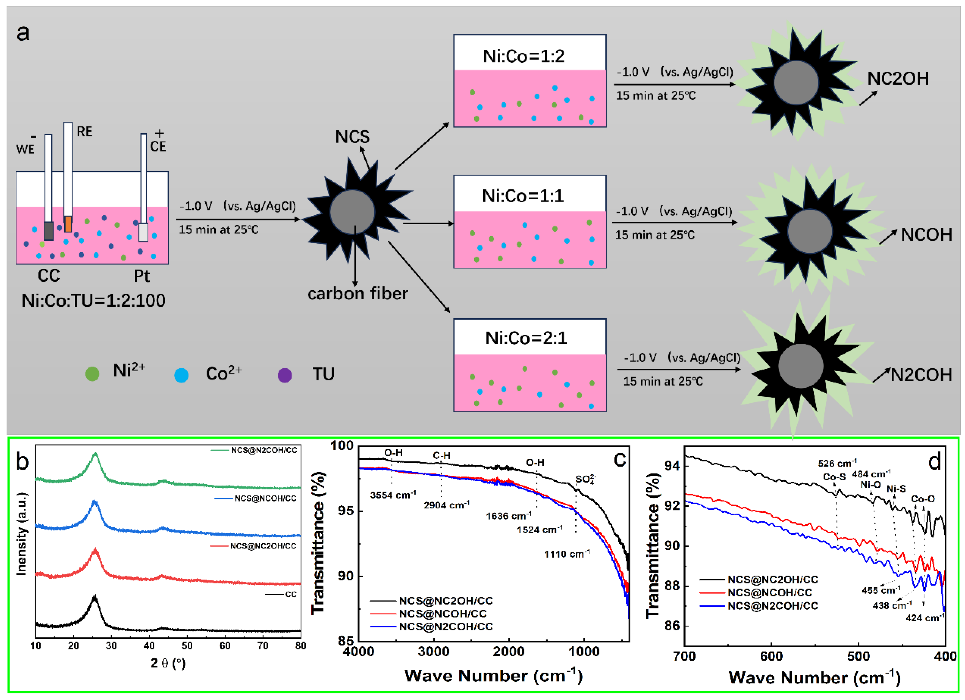
Figure 2.
XPS spectra of the NCS@NCOH/CC electrode. (a) survey spectrum, (b) Ni 2p, (c)Co 2p, (d) O 1s, (e) S 2p and (f) C 1s.
Figure 2.
XPS spectra of the NCS@NCOH/CC electrode. (a) survey spectrum, (b) Ni 2p, (c)Co 2p, (d) O 1s, (e) S 2p and (f) C 1s.
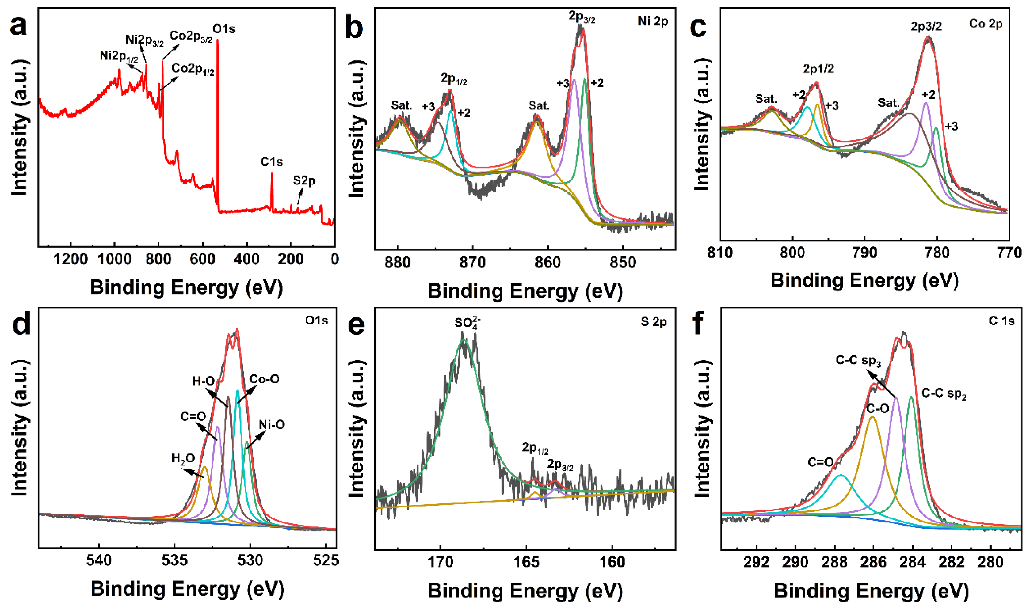
Figure 3.
SEM images of the NCS@NC2OH/CC (a1-a2), NCS@NCOH/CC (b1-b2) and NCS@N2COH/CC (c1-c2) electrodes.
Figure 3.
SEM images of the NCS@NC2OH/CC (a1-a2), NCS@NCOH/CC (b1-b2) and NCS@N2COH/CC (c1-c2) electrodes.
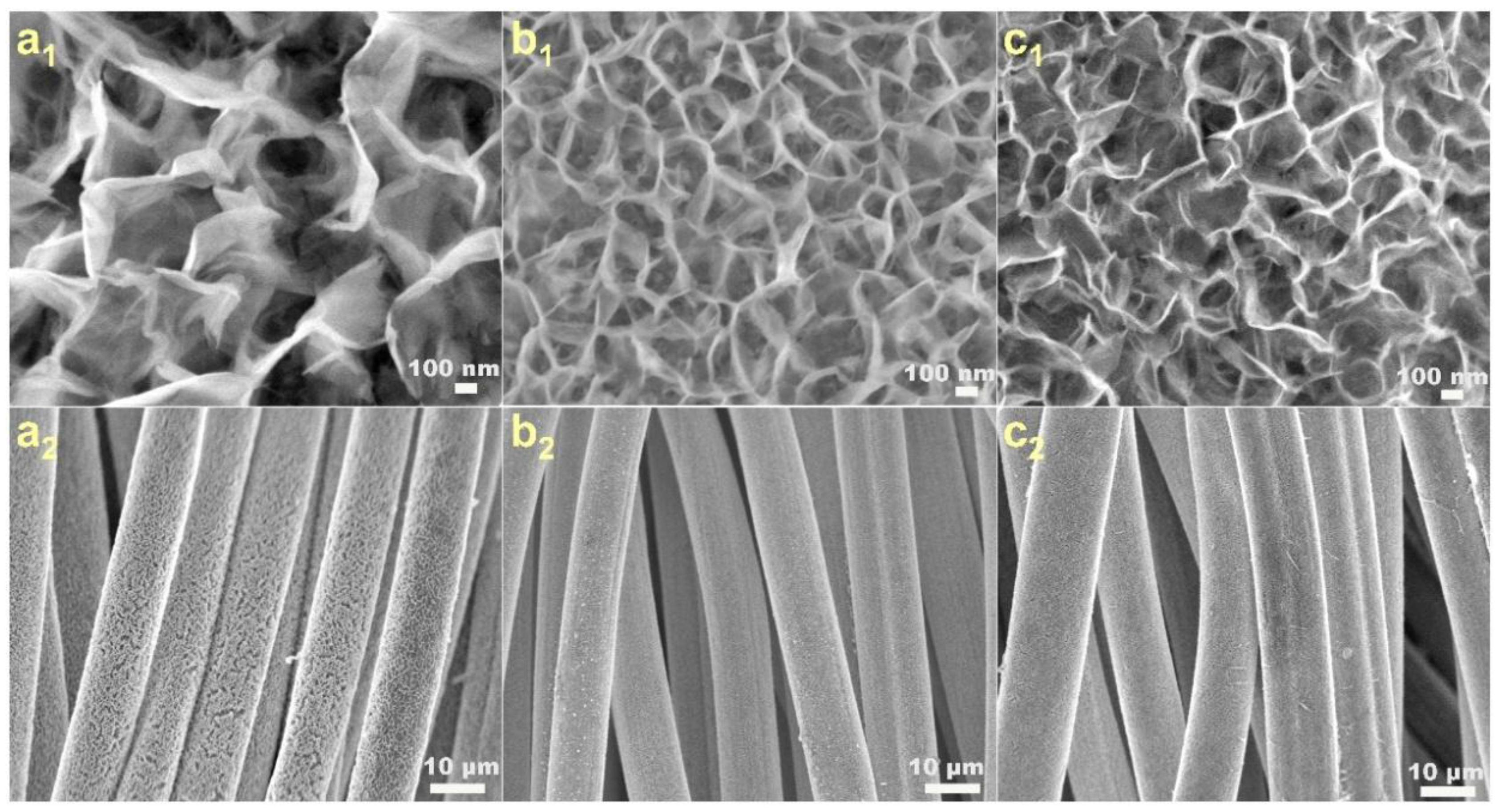
Figure 4.
(a) TEM image, (b)HRTEM image of NCS@NCOH nanoflake. Inverse FFT images of the area marked by green (c) and yellow (d) rectangles in (b). (e) EDX mappings of NCS@NCOH nanoflake.
Figure 4.
(a) TEM image, (b)HRTEM image of NCS@NCOH nanoflake. Inverse FFT images of the area marked by green (c) and yellow (d) rectangles in (b). (e) EDX mappings of NCS@NCOH nanoflake.
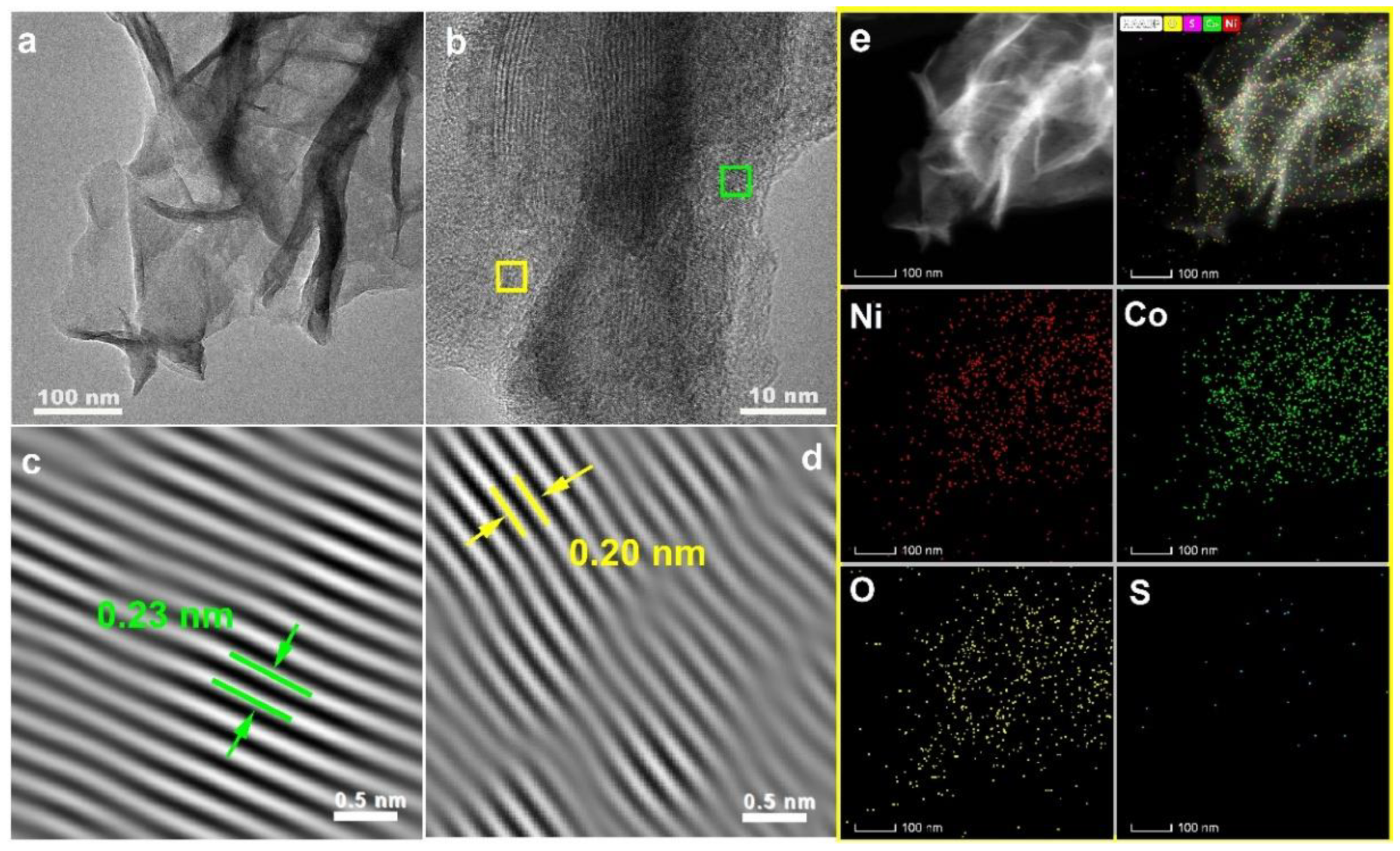
Figure 5.
(a) CV curves at 10 mV s-1, (b) initial discharge profiles at 1 A g-1, (d)rate performance, (e) cyclic performance under 10 A g-1 and (f) Nyquist plots of NCS@ NxCyOH/CC electrodes. (c) Initial discharge profiles under different current densities from 1 to 50 A g-1 of NCS@NCOH/CC electrode. The illustrations in (f) are the magnified Nyquist plots and the equivalent electric circuit for fitting the experimental data.
Figure 5.
(a) CV curves at 10 mV s-1, (b) initial discharge profiles at 1 A g-1, (d)rate performance, (e) cyclic performance under 10 A g-1 and (f) Nyquist plots of NCS@ NxCyOH/CC electrodes. (c) Initial discharge profiles under different current densities from 1 to 50 A g-1 of NCS@NCOH/CC electrode. The illustrations in (f) are the magnified Nyquist plots and the equivalent electric circuit for fitting the experimental data.
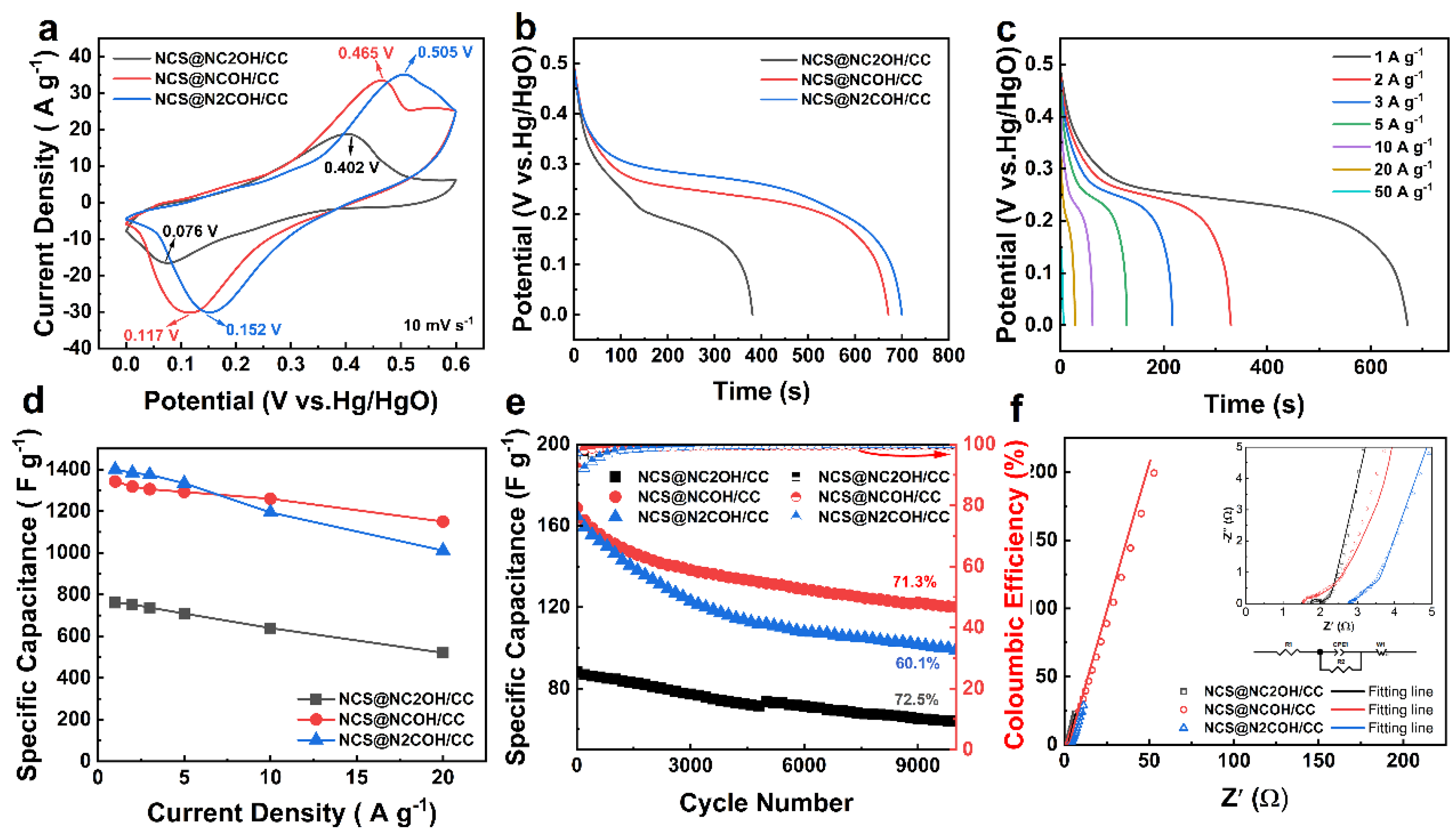
Figure 6.
(a) CV curves of NCS@NCOH/CC and AC electrodes at 10 mV s-1, (b) CV curves at various scan rates from 10 to 200 mV s-1, (c) GCD curves under various current densities from 2 to 10 A g-1, (d) rate performance, (e) cyclic performance alongside with coulombic efficiency and Ragone plot of the NCS@NCOH/CC//AC HC.
Figure 6.
(a) CV curves of NCS@NCOH/CC and AC electrodes at 10 mV s-1, (b) CV curves at various scan rates from 10 to 200 mV s-1, (c) GCD curves under various current densities from 2 to 10 A g-1, (d) rate performance, (e) cyclic performance alongside with coulombic efficiency and Ragone plot of the NCS@NCOH/CC//AC HC.
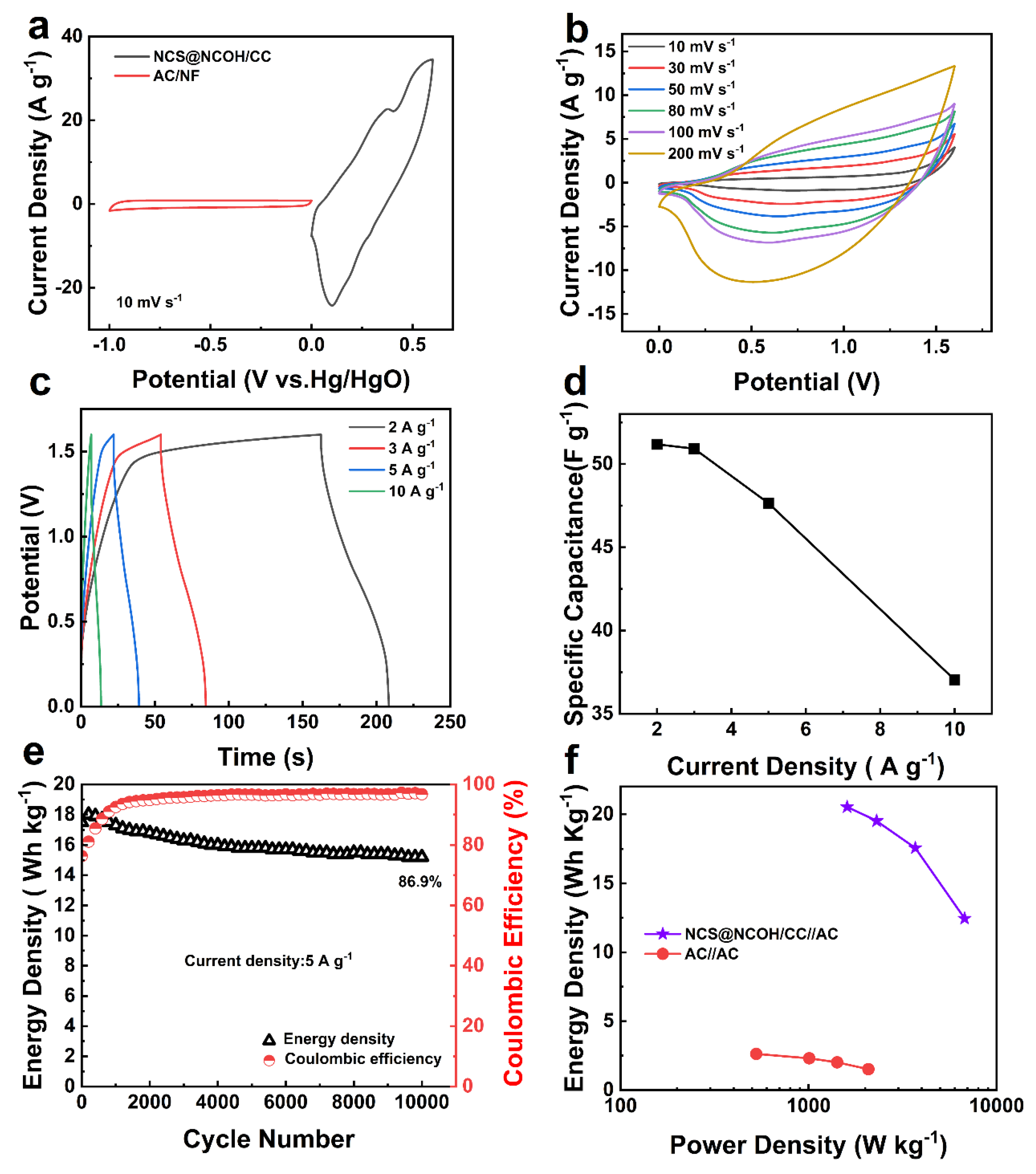
Figure 7.
(a) and (b) In situ Raman spectra of NCS@NCOH/CC electrode, the spectra were collected per 0.05 V for two charge-discharge cycles in potential window from 0 to 0.5 V (vs./HgO). (c) GCD curves under 0.7 A cm-2 for in situ Raman test.
Figure 7.
(a) and (b) In situ Raman spectra of NCS@NCOH/CC electrode, the spectra were collected per 0.05 V for two charge-discharge cycles in potential window from 0 to 0.5 V (vs./HgO). (c) GCD curves under 0.7 A cm-2 for in situ Raman test.
Disclaimer/Publisher’s Note: The statements, opinions and data contained in all publications are solely those of the individual author(s) and contributor(s) and not of MDPI and/or the editor(s). MDPI and/or the editor(s) disclaim responsibility for any injury to people or property resulting from any ideas, methods, instructions or products referred to in the content. |
© 2026 by the authors. Licensee MDPI, Basel, Switzerland. This article is an open access article distributed under the terms and conditions of the Creative Commons Attribution (CC BY) license.
Copyright: This open access article is published under a Creative Commons CC BY 4.0 license, which permit the free download, distribution, and reuse, provided that the author and preprint are cited in any reuse.


