

Submitted:
02 July 2026
Posted:
03 July 2026
You are already at the latest version
Abstract
This paper presents the integrated design and experimental verification of a ferrite spoke permanent magnet motor with rib-core skew for semiconductor process pump drives. Conventional induction motors are widely used in industrial pump systems because of their robustness and cost effectiveness; however, rotor copper loss and limited output capability under a restricted installation envelope remain practical limitations. To address these issues without rare-earth magnets, a flux-concentrating ferrite spoke rotor is applied. The proposed design procedure considers the baseline induction-motor envelope, electric and magnetic loadings, manufacturable winding specifications, voltage and current-density limits, irreversible demagnetization, and post-assembly magnetization feasibility. An 8-pole/12-slot topology is selected because it enables one-shot post-assembly magnetization, unlike the 10-pole/12-slot alternative requiring segmented magnetization. Rib-core skew and stator tooth-shoe chamfer geometries are then applied to reduce cogging torque and load torque ripple. A prototype is fabricated and tested. At 1000 rpm, the measured no-load line-to-line voltage is 21.6 Vrms. At 7000 rpm, the prototype achieves 4.028 kW output power and 93.1% efficiency. The measured post-assembly magnetization ratio is 98.7%, and the maximum winding temperature is 57.4°C at 6.68 A/mm². These results confirm the feasibility of the proposed design procedure.
Keywords:
ferrite permanent magnet motor
; spoke rotor
; rib-core skew
; tooth-shoe chamfer
; post-assembly magnetization
; integrated design
; semiconductor process pump
1. Introduction
Semiconductor and display manufacturing processes require high mechanical stability and operational reliability to ensure process accuracy and production yield. In lithography systems, precision motion stages, wafer inspection systems, and wafer handling equipment, disturbances, structural vibration, and excitation generated by drive systems can directly affect process stability [1,2,3]. Therefore, pump-drive motors used in semiconductor process facilities should satisfy not only output-power and efficiency requirements but also low electromagnetic excitation and stable operating characteristics [1,2,3,4].
Induction motors have been widely used in industrial pump systems because of their simple structure, robustness, and cost competitiveness. However, induction motors require rotor current for torque generation, which produces rotor copper loss under load. In addition, because they do not have an independent permanent excitation source in the rotor, their torque density and output density can be limited under the same motor volume [5,6]. In contrast, permanent magnet motors can reduce rotor copper loss and improve output performance and efficiency under the same installation envelope. It should be noted that stator current is still required to produce load torque in permanent magnet motors; the comparison in this study therefore concerns the reduction in rotor copper loss and excitation loss rather than current-free operation.
Rare-earth permanent magnet motors can provide high torque density and efficiency; however, the use of rare-earth magnets increases material cost and supply-chain dependency [7]. Therefore, ferrite magnets, which are relatively low-cost and supply-stable, are applied in this study. Because ferrite magnets have lower residual flux density and coercivity than rare-earth magnets, a flux-concentrating structure is required to secure sufficient air-gap flux. A spoke-type rotor concentrates the magnet flux toward the air gap by arranging magnets in the circumferential direction and is therefore suitable for compensating for the relatively low residual flux density of ferrite magnets [8,9].
Spoke-type permanent magnet motors can achieve high output performance through flux concentration; however, variations in magnetic reluctance between the rotor magnets and stator slots can increase cogging torque and load torque ripple. Cogging torque and torque ripple can act as excitation sources that are transmitted not only to the motor itself but also to the pump and surrounding structures [10,11,12,13]. Various design approaches, including rotor-shape modification, skew, step-skew, and stator/rotor geometric optimization, have been reported to reduce cogging torque and torque ripple in permanent magnet machines [14,15,16,17]. Therefore, the design of pump-drive motors for semiconductor processes should consider cogging torque and load torque ripple together with average output power, efficiency, and current density.
This paper proposes an integrated design procedure for a ferrite spoke permanent magnet motor for semiconductor process pump drives. First, the basic geometry is selected based on electric and magnetic loadings while maintaining the installation envelope of the baseline induction motor. The stack length is then determined by considering manufacturable wire diameter, number of turns, slot fill factor, voltage limit, and current-density constraint. Irreversible demagnetization and post-assembly magnetization characteristics are also evaluated, and the final pole-slot combination is selected by considering the mass-production feasibility of the magnetization process. In the detailed electromagnetic-design stage, a partial skew structure applied only to the rib-core region and a stator tooth-shoe chamfer geometry are optimized to reduce cogging torque and load torque ripple. Finally, the electromagnetic characteristics are evaluated by finite element analysis, and the no-load voltage, load performance, post-assembly magnetization ratio, and thermal saturation characteristics are experimentally verified using a prototype.
2. Target Motor and Design Requirements
2.1. Target Application and Baseline Induction Motor
The target application is a 4 kW-class pump-drive motor for semiconductor and display process equipment. The rated operating point is 4 kW at 7000 rpm, and a water-cooling condition is considered. Because the proposed motor is intended to replace a baseline induction motor, it is designed under the same main mechanical-envelope conditions. The stator outer diameter, stator inner diameter, rotor outer diameter, rotor inner diameter, and stack length of the baseline induction motor are 140 mm, 80 mm, 79.1 mm, 30.3 mm, and 85 mm, respectively.
The finite element analysis of the baseline induction motor resulted in a shaft torque of 5.58 N·m, output power of 3758.84 W, efficiency of 86.24%, and current density of 6.3 A/mm² at 6435.1 rpm. In this study, a ferrite permanent magnet motor is designed to satisfy the target operating point of 7000 rpm and 4 kW while maintaining the installation envelope of the baseline induction motor. Because the operating points of the baseline induction motor and the proposed model are not identical, the focus is placed on achieving the target performance within the restricted installation envelope rather than directly comparing percentage improvements.
Figure 1.
Geometry of the baseline induction motor.
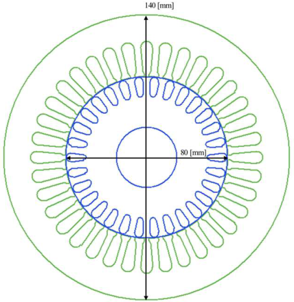

Table 1.
Main performance characteristics of the baseline induction motor.
| Parameter | MEC | FEM | Unit |
|---|---|---|---|
| Torque | 5.9 | 5.58 | N·m |
| Torque ripple | - | 1.46 | N·m |
| Speed | 6143.6 | 6435.1 | rpm |
| Current | 8.1 | 7.3 | Arms |
| Current Density | 7.0 | 6.3 | A/mm² |
| Copper Loss | 225.4 | 183.1 | W |
| Core Loss | 45.3 | 35.9 | W |
| Mechanical Loss | 220.0 | 220.0 | W |
| Stray Loss | 40.0 | 40.0 | W |
| Output Power | 3960.3 | 3758.8 | W |
| Input Power | 4625.2 | 4358.5 | W |
| Efficiency | 85.62 | 86.24 | % |
2.2. Voltage Limit and Main Design Conditions
Considering the 380 Vrms commercial input supply and inverter operating conditions, the fundamental line-to-line voltage limit under load is set to 410.5 V. A 20% voltage margin is applied to account for voltage variation and operating reserve.
2.3. Main Design Requirements
The main design requirements applied in this study are summarized in Table 2. The primary constraints are output power, speed, current density, irreversible demagnetization ratio, post-assembly magnetization ratio, and load torque ripple. Output density and motor vibration are not treated as primary constraints in this paper but are used as supplementary indices when discussing the design results and application feasibility.
2.4. Pole-Slot Combination Review and Final Topology Selection
A concentrated-winding structure is applied to reduce the end-winding length and secure high output and efficiency within the restricted installation envelope. A ferrite spoke-type rotor is also selected to compensate for the relatively low residual flux density of ferrite magnets and to enable post-assembly magnetization. In the initial design stage, 8-pole/12-slot and 10-pole/12-slot combinations are compared by considering the winding factor, output performance, and post-assembly magnetization process. Although the 10-pole/12-slot model shows favorable electromagnetic characteristics in several aspects, a five-step segmented magnetization process is required to secure sufficient magnetization performance under the limited capacity of the magnetizer. Segmented magnetization is disadvantageous for mass production because it increases the process time and magnetization-process complexity. In contrast, the 8-pole/12-slot model can be magnetized through a one-shot post-assembly process. Therefore, the 8-pole/12-slot spoke model is selected as the final design target by considering the simplicity and manufacturability of the mass-production process.
Table 3.
Comparison of preliminary models and post-assembly magnetization processes according to the pole-slot combination.
Table 3.
Comparison of preliminary models and post-assembly magnetization processes according to the pole-slot combination.
| Parameter | 8-pole/12-slot | 10-pole/12-slot | Selection criterion |
|---|---|---|---|
| Output power | 4.67 kW | 5.12 kW | Both models satisfy the output target |
| Current density | 6.8 A/mm² | 6.9 A/mm² | Both models satisfy the current-density limit |
| Load torque ripple | 45.7% | 17.6% | Detailed electromagnetic optimization is required |
| Post-assembly magnetization process |
One-shot magnetization |
Five-step segmented magnetization |
Segmented magnetization increases process complexity |
| Mass-production feasibility | Relatively favorable |
Relatively unfavorable |
8-pole/12-slot topology selected |
3. Integrated Design of the Ferrite Spoke Permanent Magnet Motor
3.1. Overall Design Process
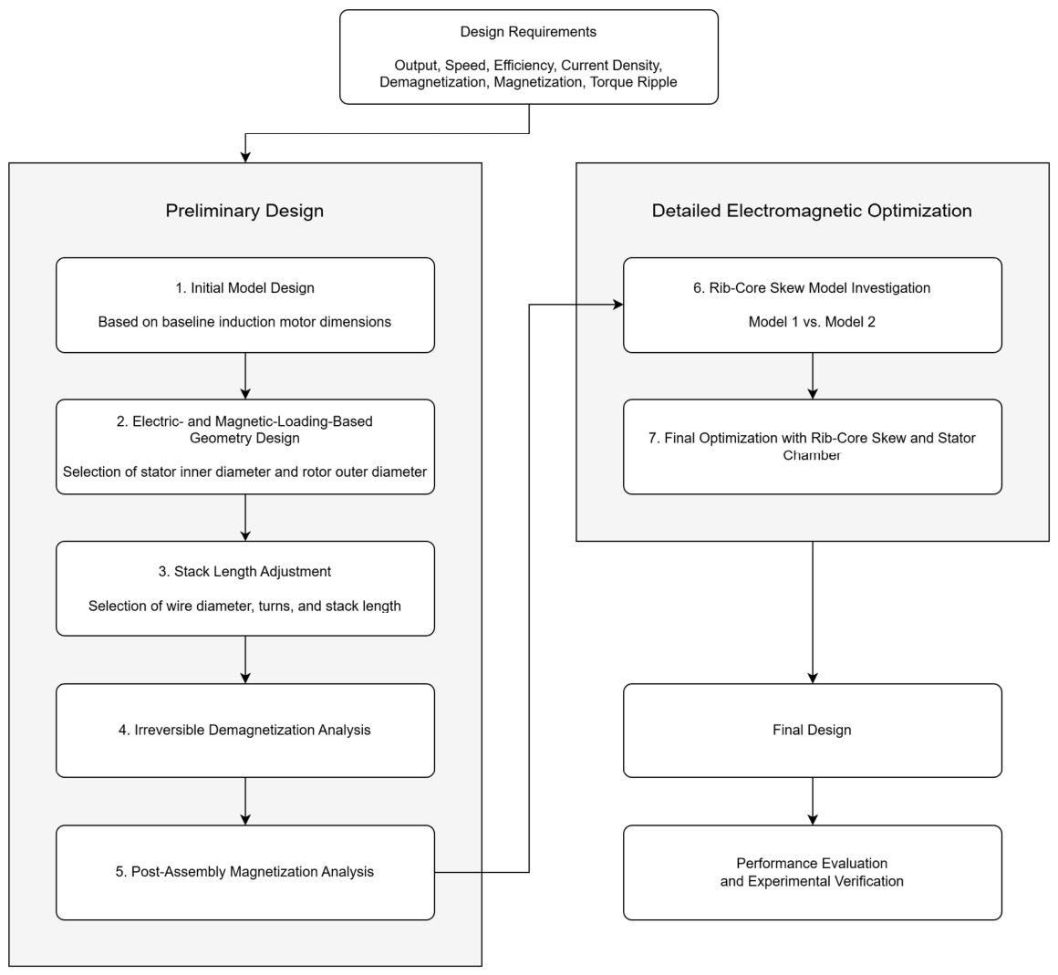
The proposed motor-design procedure is divided into a preliminary design stage and a detailed electromagnetic-optimization stage. In the preliminary design stage, the major design variables affecting output power, efficiency, current density, output margin, irreversible demagnetization, and post-assembly magnetization feasibility are determined. In the detailed electromagnetic-optimization stage, the rib-core skew and stator tooth-shoe chamfer geometries are optimized to reduce cogging torque and load torque ripple.
Figure 2.
Overall design process of the proposed ferrite spoke permanent magnet motor.
3.2. Initial Model Based on the Baseline Induction Motor
The initial model is designed using the same stator and rotor inner and outer diameters and the same stack length as the baseline induction motor. The required shaft torque at the target output power and speed is calculated as follows:
where is the target output power, is the mechanical angular velocity, and n is the rotational speed. The required shaft torque is approximately 5.46 N·m at 4 kW and 7000 rpm.
At 7000 rpm, the initial 8-pole/12-slot model produces a no-load phase back-EMF of 97.7 Vrms, a fundamental no-load line-to-line voltage of 238.0 V, and a cogging torque of 0.24 N·m. Under load, the current, current density, shaft torque, output power, and efficiency are 11.4 Arms, 4.3 A/mm², 5.50 N·m, 4.03 kW, and 95.8%, respectively. Although the output target is satisfied, the load torque ripple is 51.2%, indicating the need for additional optimization.
Figure 3.
Geometry of the initial 8-pole/12-slot model.
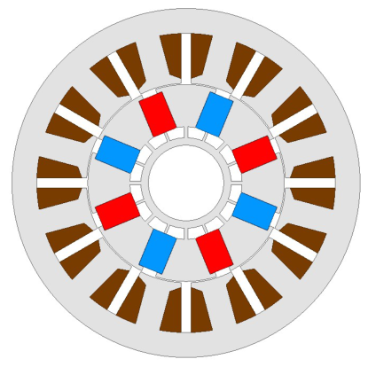
Table 4.
Geometry and electromagnetic characteristics of the initial 8-pole/12-slot model.
| Parameter | FEM | Unit |
|---|---|---|
| Speed | 7000 | rpm |
| No-load phase back-EMF | 97.7 | Vrms |
| No-load line-to-line voltage | 238.0 | V |
| No-load Line-to-line back-EMF THD | 10.1 | % |
| Cogging torque | 0.24 | N·m |
| Current | 11.4 | Arms |
| Current density | 4.3 | A/mm² |
| Current Phase Angle | 28 | deg |
| Phase Resistance(@25℃) | 0.11 | Ω |
| Shaft torque | 5.5 | N·m |
| Torque ripple | 51.2 | % |
| Load line-to-line voltage | 408.1 | V |
| Load Line-to-line back-EMF THD | 13.8 | % |
| Copper Loss | 44.8 | W |
| Core Loss | 133.0 | W |
| Output power | 4.03 | kW |
| Output density | 3.06 | kW/L |
| Efficiency | 95.8 | % |
3.3. Preliminary Geometry Design Based on Electric and Magnetic Loadings
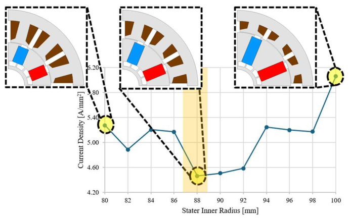
After establishing the initial model, the stator inner diameter and rotor outer diameter are varied under the same stator outer-diameter condition to examine the balance between electric and magnetic loadings. Increasing the stator inner diameter enlarges the rotor outer diameter and the available magnet space, which can increase the magnetic loading. However, the slot area decreases simultaneously, which is disadvantageous in terms of electric loading. Therefore, the slot area, number of turns, wire diameter, slot fill factor, no-load line-to-line voltage, and estimated current density are calculated for each stator inner-diameter condition, and the geometry with the lowest current density is selected.
The number of turns is determined based on the target fundamental no-load line-to-line voltage as follows:
where V_ref is the reference fundamental no-load line-to-line voltage and e_1turn is the fundamental no-load line-to-line voltage per turn. The slot fill factor is calculated as follows:
factor, no-load line-to-line voltage, and estimated current density are calculated for each stator inner-diameter condition, and the geometry with the lowest current density is selected.
where A_wire,ins is the cross-sectional area of the insulated wire and A_slot is the effective slot area. The estimated current and current density based on the magnetic-torque component are calculated as follows:
where , 0 is the no-load phase back-EMF, a is the number of parallel circuits, and is the cross-sectional area of the bare conductor. The lowest current density is obtained with a stator inner diameter of 88 mm and a rotor outer diameter of 87 mm. Therefore, this condition is selected as the preliminary geometry.
Figure 4.
Estimated current density according to the stator inner diameter and selection of the preliminary geometry.
Figure 4.
Estimated current density according to the stator inner diameter and selection of the preliminary geometry.
3.4. Manufacturable Winding Specifications and Stack-Length Selection
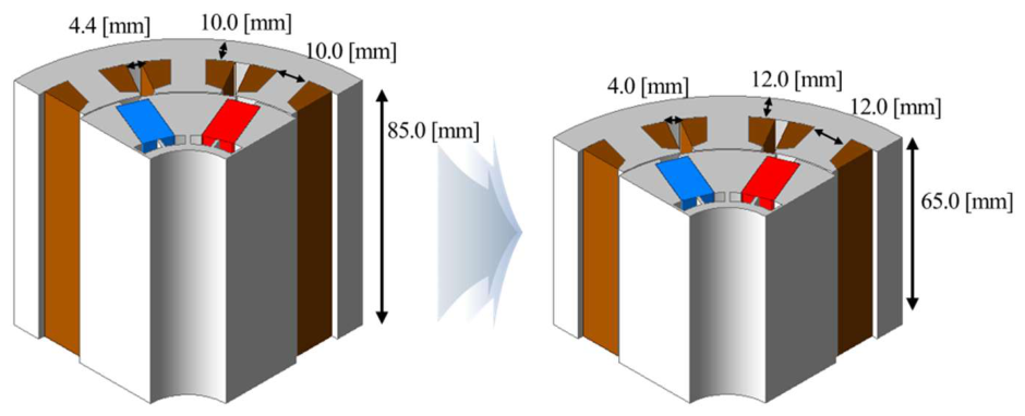
After selecting the preliminary geometry, the stack length is adjusted by considering output-density improvement and manufacturability. A wire diameter of 1.1 mm and 41 turns are initially selected for the compact preliminary model by considering automatic winding and the slot fill-factor constraint. Because the back-EMF is approximately proportional to the number of turns and stack length, the stack length required to maintain the target voltage can be estimated using the following relationships:
For the original condition, = 31 and = 85 mm. When = 41 is applied, the calculated stack length is approximately 64.3 mm. Accordingly, the final stack length is selected as 65 mm by considering manufacturability and the finite element analysis condition.
At 7000 rpm, the stack-length-adjusted model produces a no-load phase back-EMF of 98.2 Vrms, a no-load line-to-line voltage of 239.1 V, a current of 13 Arms, a current density of 6.8 A/mm², a shaft torque of 6.37 N·m, an output power of 4.67 kW, and an efficiency of 95.8%. The output density increases to 4.67 kW/L. However, the load torque ripple remains high at 45.7%, and detailed electromagnetic optimization is required.
Figure 5.
Stack-length adjustment and characteristics of the compact preliminary model.
3.5. Irreversible Demagnetization and Post-Assembly Magnetization Review
3.5.1. Irreversible Demagnetization Analysis
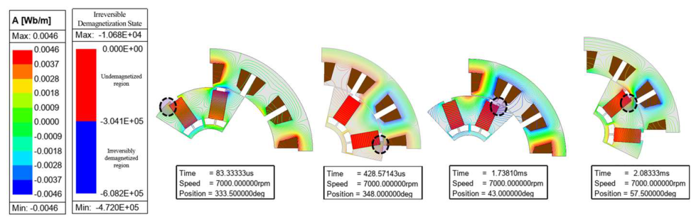
Because ferrite magnets have lower coercivity than rare-earth magnets, the possibility of irreversible demagnetization should be evaluated under an overcurrent condition [18,19]. In this study, an irreversible demagnetization analysis is conducted over one electrical period under a three-times-rated-current condition. The irreversible demagnetization ratio is defined based on the change in back-EMF before and after the demagnetization analysis:
The back-EMF values before and after the demagnetization analysis are 115.7 Vrms and 115.5 Vrms, respectively. The corresponding irreversible demagnetization ratio is 0.2%, satisfying the requirement of 3% or lower.
Figure 6.
Irreversible demagnetization distributions at selected rotor positions under the three-times-rated-current condition.
Figure 6.
Irreversible demagnetization distributions at selected rotor positions under the three-times-rated-current condition.
3.5.2. Post-Assembly Magnetization Analysis
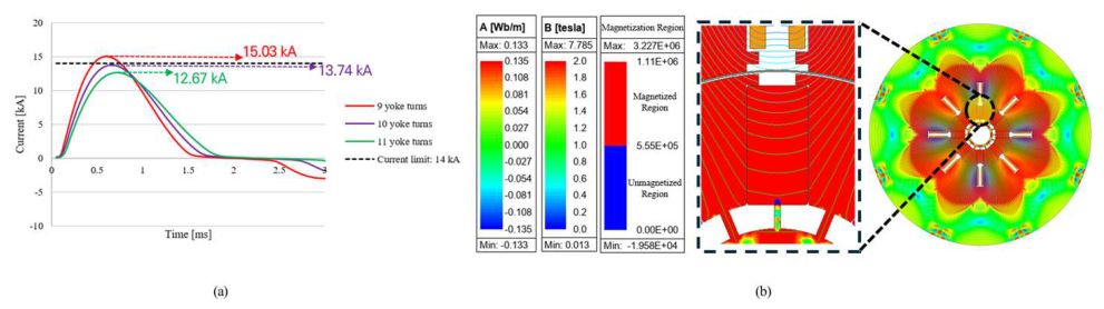
Because the magnets of a spoke-type rotor are inserted inside the rotor, the feasibility of post-assembly magnetization should be evaluated in advance [20,21]. In this study, the magnetization analysis is conducted under a magnetization voltage of 3500 V, capacitance of 3000 µF, and maximum allowable current of 14000 A. These conditions are set by considering the capacity of a magnetizer applicable to mass-production processes. The post-assembly magnetization ratio is defined as follows:
For the preliminary model, the back-EMF values before and after post-assembly magnetization are 98.2 Vrms and 97.6 Vrms, respectively. The corresponding post-assembly magnetization ratio is 99.4%, satisfying the design requirement of 97% or higher.
Figure 7.
Post-assembly magnetization analysis results. (a) Magnetizing-current waveforms, (b) Post-assembly magnetization distribution.
Figure 7.
Post-assembly magnetization analysis results. (a) Magnetizing-current waveforms, (b) Post-assembly magnetization distribution.
3.6. Rib-Core Skew and Stator Tooth-Shoe Chamfer Optimization
3.6.1. Rib-Core Skew Design
Although the preliminary design model satisfies the output-power, voltage, current-density, irreversible-demagnetization, and post-assembly-magnetization requirements, its load torque ripple remains relatively high. Therefore, a rib-core skew structure is applied as the first step of the detailed electromagnetic optimization to reduce cogging torque.
A conventional full-rotor skew reduces cogging torque by shifting the phase of the cogging-torque waveform along the axial direction and partially canceling the cogging-torque components generated at different cross sections [11,14,17,22,23,24]. However, a full-rotor skew can increase the complexity of the rotor-fabrication and post-assembly-magnetization processes. In this study, a partial-skew structure is therefore applied by modifying only the rib-core region of the spoke-type rotor without twisting the entire rotor geometry. The rotor stack is divided axially, and opposite rib-core geometries are applied to the corresponding cross sections to introduce a phase difference between the cogging-torque waveforms. This approach provides a cogging-torque cancellation effect while preserving the main rotor structure.
Figure 8.
Principle of the rib-core skew and opposite skew directions applied to the axial cross sections.
Figure 8.
Principle of the rib-core skew and opposite skew directions applied to the axial cross sections.
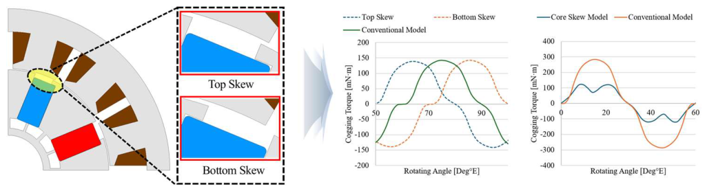
To determine the rib-core skew length, the length of the one-sided rib-core region is progressively varied from the original rib geometry within the geometrically allowable range. For each condition, the no-load phase back-EMF and cogging torque are evaluated. As the rib-core skew length increases, the cogging torque generally decreases, whereas the no-load phase back-EMF also tends to decrease. Therefore, the final geometry is selected by considering the trade-off between cogging-torque reduction and back-EMF reduction.
Figure 9.
Rib-core skew-length sweep and selection of the final geometry: (a) definition and geometrically allowable range of the rib-core skew length, (b) selected geometry with a rib-core skew length of 3.3 mm, and (c) variations in cogging torque and no-load phase back-EMF according to the rib-core skew length.
Figure 9.
Rib-core skew-length sweep and selection of the final geometry: (a) definition and geometrically allowable range of the rib-core skew length, (b) selected geometry with a rib-core skew length of 3.3 mm, and (c) variations in cogging torque and no-load phase back-EMF according to the rib-core skew length.
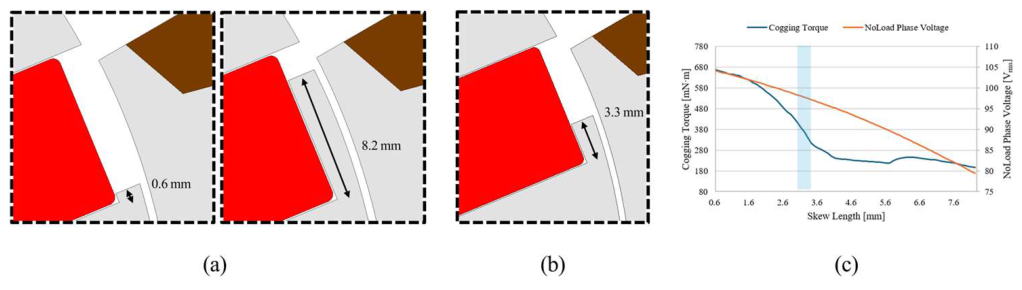
The parameter-sweep results show that a rib-core skew length of 3.3 mm provides a substantial cogging-torque reduction while limiting the decrease in back-EMF. Under this condition, the no-load phase back-EMF is 98.2 Vrms, and the cogging torque is 340 mN·m. Therefore, the rib-core skew length of 3.3 mm is selected for the final geometry and is subsequently applied in the stator tooth-shoe chamfer optimization stage.
3.6.2. Stator Tooth-Shoe Chamfer Optimization
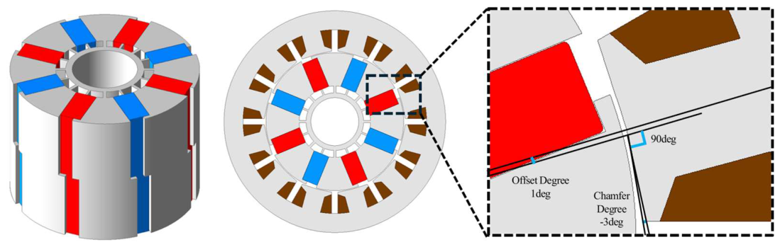
A stator tooth-shoe chamfer geometry is subsequently optimized to satisfy the load torque-ripple requirement after applying the rib-core skew. The design variables are defined as an offset angle measured from the reference axis connecting the slot center and the origin and a chamfer angle used to cut the tooth shoe relative to the offset axis. A minimum shoe thickness of 0.6 mm is applied as a geometric constraint, and geometrically meaningless taper conditions are excluded.
Based on the parameter sweep, the final geometry is selected as the model with the largest shaft torque among the candidates satisfying the torque-ripple requirement. The final offset angle and chamfer angle are 1° and −3°, respectively. The final model produces a no-load phase back-EMF of 96.4 Vrms, cogging torque of 316 mN·m, and load torque ripple of 9.56%. Relative to the preliminary model, the back-EMF decreases by 1.8%, while the cogging torque and load torque ripple decrease by 44.6% and 79.0%, respectively.
Figure 10.
Definition of the stator tooth-shoe chamfer variables and geometric constraints.
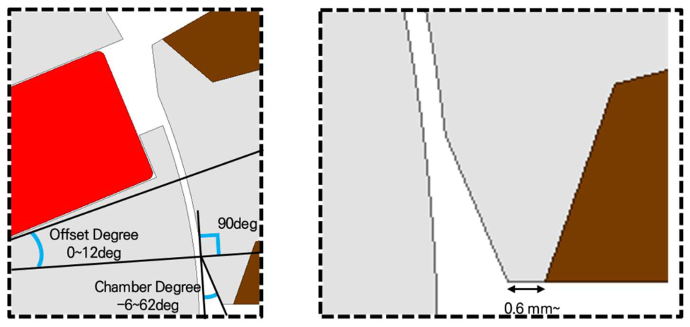
Figure 11.
Parameter-sweep results for the stator tooth-shoe chamfer: (a) peak-to-peak cogging torque, (b) mean load torque, (c) no-load phase back-EMF, and (d) load torque ripple.
Figure 11.
Parameter-sweep results for the stator tooth-shoe chamfer: (a) peak-to-peak cogging torque, (b) mean load torque, (c) no-load phase back-EMF, and (d) load torque ripple.
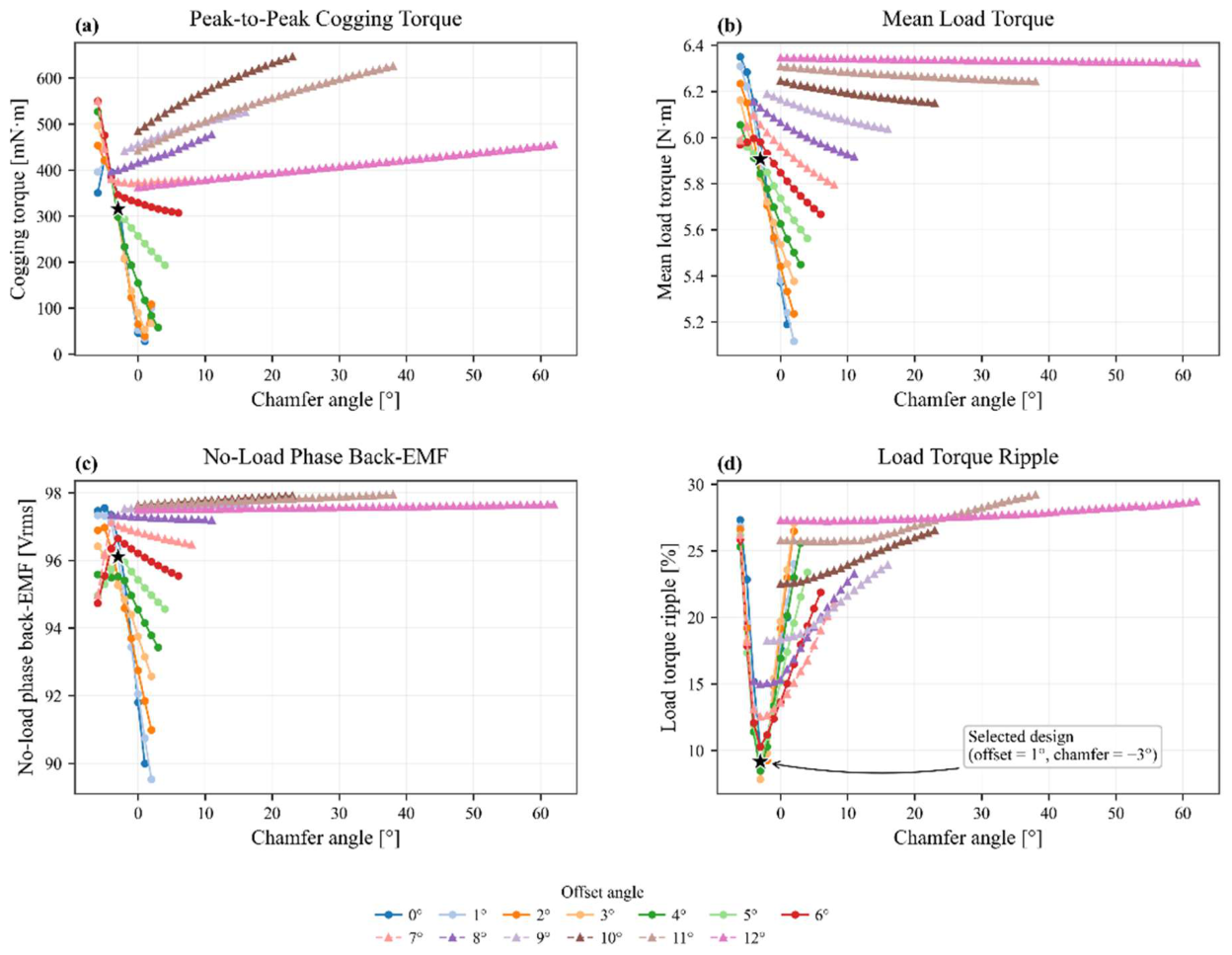
Figure 12.
Comparison of feasible stator tooth-shoe chamfer candidates satisfying the load-torque-ripple constraint: (a) mean load torque and (b) load torque ripple.
Figure 12.
Comparison of feasible stator tooth-shoe chamfer candidates satisfying the load-torque-ripple constraint: (a) mean load torque and (b) load torque ripple.
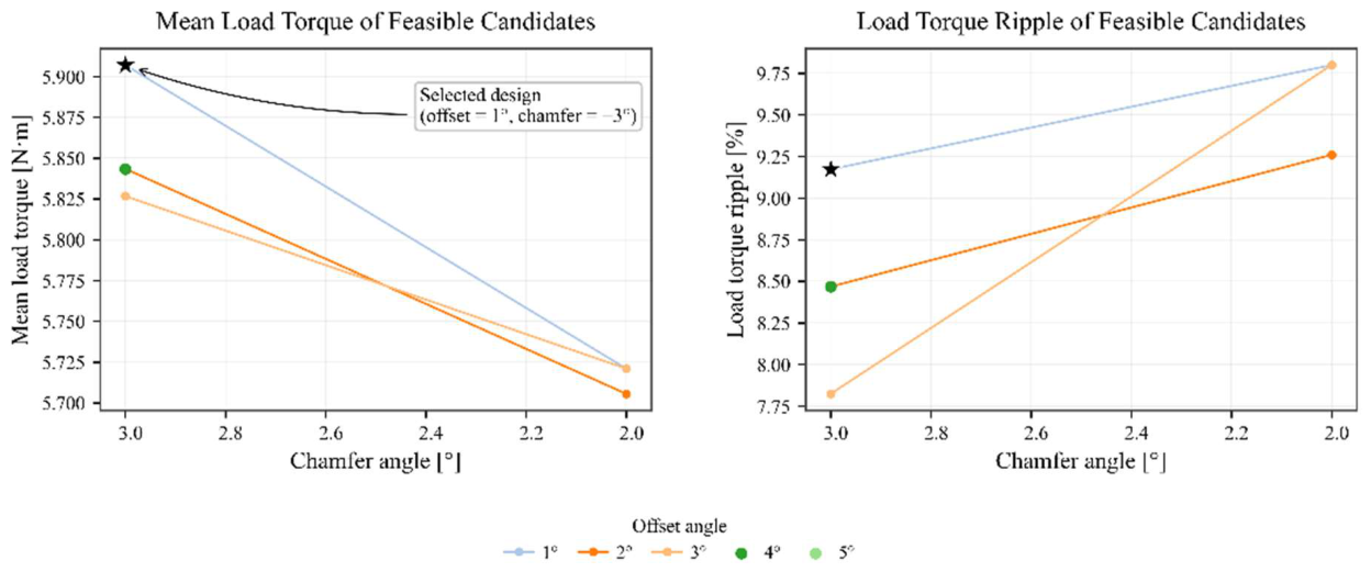
Figure 13.
Final tooth-shoe chamfer geometry and performance of the optimized model.
3.7. Manufacturing-Considered Three-Dimensional Final Model and Performance Changes
After the two-dimensional electromagnetic optimization, the optimized model was converted into a manufacturing-considered three-dimensional model for prototype fabrication and experimental comparison. In the compact preliminary design, 41 turns with a wire diameter of 1.1 mm were initially selected by considering the voltage limit, slot fill factor, and winding manufacturability. During the prototype winding process, the feasibility of one additional turn was confirmed; therefore, the final prototype winding specification was adjusted from 41 to 42 turns. The prototype model also reflects the split-stator-core structure, rotor fixing holes, shaft-inner-diameter adjustment, and other assembly-related geometric modifications.
Table 5 summarizes the representative performance changes from the initial model to the prototype test. The rib-core skew and stator tooth-shoe chamfer are included together as the detailed electromagnetic-optimization stage because the rib-core skew effect is discussed separately in Figure 9.
The two-dimensional optimized model produces a no-load phase back-EMF of 96.4 Vrms, a no-load line-to-line voltage of 236.3 V, a line-to-line back-EMF THD of 2.06%, and a cogging torque of 316 mN·m at 7000 rpm. Under load, the current, current density, shaft torque, output power, efficiency, and load torque ripple are 13 Arms, 6.8 A/mm², 5.77 N·m, 4.229 kW, 96.3%, and 9.56%, respectively. Therefore, the optimized electromagnetic model satisfies the output-power, current-density, and load-torque-ripple requirements.
Table 6.
Main electromagnetic characteristics of the two-dimensional optimized model.
| Parameter | Value |
|---|---|
| Speed | 7000 rpm |
| No-load phase back-EMF | 96.4 Vrms |
| No-load line-to-line voltage | 236.3 V |
| Line-to-line back-EMF THD | 2.06% |
| Cogging torque | 316 mN·m |
| Current | 13 Arms |
| Current density | 6.8 A/mm² |
| Shaft torque | 5.77 N·m |
| Output power | 4.229 kW |
| Efficiency | 96.3% |
| Load torque ripple | 9.56% |
| Post-assembly magnetization ratio | 99.6% |
4. Prototype Fabrication and Experimental Verification
4.1. Prototype and Experimental Setup
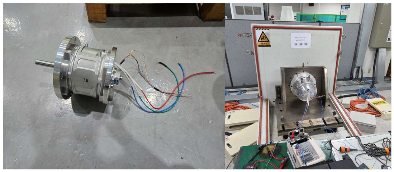
A prototype of the proposed 4 kW-class ferrite spoke permanent magnet motor is fabricated to verify the feasibility of the proposed design. The experimental verification consists of no-load, load, and thermal saturation tests. In the no-load test, the phase-to-phase resistance, phase-to-phase inductance, no-load line-to-line voltage, and cogging torque are measured. In the load test, the current, current density, shaft torque, output power, and efficiency are measured under the rated-output condition. In the thermal saturation test, the winding and housing temperatures are measured under a current condition close to the rated value. The load torque ripple and irreversible demagnetization ratio are evaluated in the finite element analysis stage and are not included in the direct experimental verification.
Figure 14.
Prototype and experimental setup.
4.2. No-Load Test Results
The measured U–V, V–W, and W–U phase-to-phase resistances are 274.85 mΩ, 275.79 mΩ, and 275.25 mΩ, respectively, with an average value of 275.30 mΩ. The maximum phase-to-phase resistance deviation is 0.342%. Depending on the rotor position, the average minimum and maximum phase-to-phase inductances are 4.423 mH and 6.152 mH, respectively.
The no-load line-to-line voltage is measured at 1000 rpm and compared with the three-dimensional finite element analysis result. The calculated and measured RMS values are 22.1 Vrms and 21.6 Vrms, respectively, corresponding to an error of approximately 2.3%. Figure 15a compares the calculated and measured no-load line-to-line voltage waveforms.
The calculated and measured peak-to-peak cogging-torque values are 283.9 mN·m and 383.6 mN·m, respectively, corresponding to an error of approximately 35.1%. Figure 15b compares the calculated and measured cogging-torque waveforms. The discrepancy in cogging torque can be attributed to manufacturing tolerances, assembly eccentricity, lamination conditions, and measurement conditions.
4.3. Post-Assembly Magnetization Test Results
The feasibility of post-assembly magnetization is evaluated using the surface magnetic flux-density distribution and the no-load line-to-line voltage. Figure 16 compares the calculated and measured surface magnetic flux-density waveforms along the rotor circumference after post-assembly magnetization. The measured waveform shows a distribution similar to the finite element analysis result, indicating that the post-assembly magnetization process produces an overall magnetization distribution consistent with the calculated result.
The post-assembly magnetization ratio is quantitatively evaluated using the no-load line-to-line voltage. At 1000 rpm, the no-load line-to-line voltages of the assembly with individually magnetized magnets and the post-assembly-magnetized prototype are 21.9 Vrms and 21.6 Vrms, respectively. The corresponding post-assembly magnetization ratio is 98.7%, satisfying the design requirement of 97% or higher. Therefore, the post-assembly magnetization process is considered applicable in terms of electromagnetic performance.
4.4. Load Test Results
The load test is conducted at 7000 rpm. Under the rated-output condition, the measured current, current density, shaft torque, output power, and efficiency are 14.0 Arms, 6.19 A/mm², 5.49 N·m, 4028.1 W, and 93.1%, respectively. Therefore, the prototype satisfies the target output power of 4 kW and the current-density limit of 7 A/mm² or lower.
Under the rated-load condition, the measured current is approximately 14.8% higher than the calculated value, and the measured efficiency is 3.3 percentage points lower than the calculated value. These differences can be affected by the actual slot fill factor, winding resistance, core loss, mechanical loss, assembly tolerances, and control conditions. In particular, when the current phase angle is limited under sensorless control, a difference can occur between the optimal phase angle assumed in the finite element analysis and the actual operating condition.
Table 7.
Comparison of the calculated and measured load-test results at 7000 rpm.
| Parameter | FEM | Measurement | Unit |
|---|---|---|---|
| Speed | 7000 | 7000 | rpm |
| Current | 12.2 | 14.0 | Arms |
| Current density | 5.39 | 6.19 | A/mm² |
| Shaft torque | 5.52 | 5.49 | N·m |
| Output power | 4.048 | 4.028 | kW |
| Efficiency | 96.4 | 93.1 | % |
4.5. Thermal Saturation Test Results
The thermal saturation test is conducted under a current density of 6.68 A/mm². The temperatures of the housing inner surface, end winding, and winding mid-section are measured until thermal saturation. As shown in Figure 17, the winding temperatures gradually increase and reach a saturated state after approximately 30 min. The maximum temperature is observed at the winding mid-section and reaches 57.4 °C.
4.6. Discussion of Experimental Results
The prototype satisfies the target output-power and current-density requirements. The measured no-load line-to-line voltage agrees with the three-dimensional finite element analysis result within 2.2%. Although the measured cogging torque is higher than the calculated value, this discrepancy can be affected by manufacturing and assembly tolerances and by the measurement conditions. The measured voltage-based post-assembly magnetization ratio is 98.7%, satisfying the design requirement of 97% or higher. The load torque ripple is evaluated in the finite element analysis stage and is not directly measured in the prototype test.
The measured efficiency is lower than the calculated value but reaches 93.1% under the rated-output condition. For mass-production design, a conservative design approach considering the actual slot fill factor and winding resistance, current-phase-angle optimization considering the control conditions, and enhanced three-dimensional post-assembly-magnetization analysis considering the magnetizer performance are required.
5. Conclusions
This paper proposes an integrated design procedure for a ferrite spoke permanent magnet motor with rib-core skew for semiconductor process pump drives and verifies its feasibility through prototype tests. The proposed motor is designed to satisfy the target operating point of 7000 rpm and 4 kW while maintaining the installation envelope of a baseline induction motor. A flux-concentrating spoke rotor is applied to compensate for the relatively low residual flux density of ferrite magnets.
In the preliminary design stage, a wire diameter of 1.1 mm and 41 turns are initially selected by considering the voltage limit, slot fill factor, and winding manufacturability. During the prototype winding process, the final winding specification is adjusted to 42 turns, and this specification is reflected in the manufacturing-considered three-dimensional model and prototype fabrication. The stack length is then adjusted to 65 mm to satisfy the voltage-limit and slot-fill-factor conditions. The irreversible demagnetization analysis under a three-times-rated-current condition results in an irreversible demagnetization ratio of 0.2%. For the post-assembly magnetization process, the 10-pole/12-slot model requires five-step segmented magnetization, whereas the 8-pole/12-slot model can be magnetized through a one-shot process. Therefore, the 8-pole/12-slot model is selected by considering the simplicity of the mass-production process.
In the detailed electromagnetic-optimization stage, rib-core skew and stator tooth-shoe chamfer geometries are applied. The rib-core skew length of 3.3 mm reduces the cogging torque while limiting the back-EMF reduction, and the subsequent tooth-shoe chamfer optimization decreases the calculated load torque ripple to 9.56%. In the optimized geometry, the offset angle and chamfer angle are 1° and −3°, respectively. The optimized electromagnetic model produces an output power of 4.229 kW, a current density of 6.8 A/mm², and an efficiency of 96.3% at 7000 rpm.
In the prototype tests, the measured no-load line-to-line voltage at 1000 rpm is 21.6 Vrms, corresponding to an error of 2.2% relative to the calculated value of 22.1 Vrms. The voltage-based post-assembly magnetization ratio is 98.7%, satisfying the requirement of 97% or higher. In the load test at 7000 rpm, the prototype achieves an output power of 4028.1 W, a shaft torque of 5.49 N·m, a current density of 6.19 A/mm², and an efficiency of 93.1%. In the thermal saturation test, the maximum temperature at the middle of the winding is 57.4 °C under a current density of 6.68 A/mm², confirming thermally stable operation.
Therefore, this study establishes an integrated design procedure for a ferrite spoke permanent magnet motor by considering a restricted installation envelope and a post-assembly magnetization process applicable to mass production. The electromagnetic characteristics associated with the rib-core skew and stator tooth-shoe chamfer are evaluated by finite element analysis, and the no-load voltage, post-assembly magnetization ratio, load output power, efficiency, and thermal stability are experimentally verified using a prototype.
Author Contributions
Conceptualization, J.-H.K.; methodology, J.-H.K. and S.-H.L.; software, J.-H.K.; validation, J.-H.K. and S.-B.K.; formal analysis, J.-H.K.; investigation, J.-H.K., S.-H.L. and S.-B.K.; resources, D.-H.J.; data curation, J.-H.K.; writing—original draft preparation, J.-H.K.; writing—review and editing, D.-H.J. and W.-H.K.; visualization, J.-H.K.; supervision, W.-H.K.; project administration, D.-H.J.; funding acquisition, D.-H.J. All authors have read and agreed to the published version of the manuscript.
Funding
This research was funded by the Ministry of SMEs and Startups (MSS, Republic of Korea) through the Technology Development Program (RS-2024-00470254).
Institutional Review Board Statement
Not applicable.
Informed Consent Statement
Not applicable.
Data Availability Statement
The data presented in this study are available on request from the corresponding author.
Conflicts of Interest
The authors declare no conflicts of interest.
References
- Amick, H.; Gendreau, M.; Busch, T.; Gordon, C. Evolving Criteria for Research Facilities: I—Vibration. Proc. SPIE 5933, Buildings for Nanoscale Research and Beyond, 2005. [Google Scholar]
- Butler, H. Acceleration Feedback in a Lithographic Tool. Control Eng. Pract. 2012, 20, 453–464. [Google Scholar] [CrossRef]
- Butler, H. Fractional-Order Filters for Active Damping in a Lithographic Tool. Control Eng. Pract. 2013, 21, 278–285. [Google Scholar] [CrossRef]
- Choi, D.-H.; Yang, I.-J.; Hong, M.-K.; Jung, D.-H.; Kim, W.-H. High-Speed Design with Separated Tapering for Reducing Cogging Torque and Torque Ripple of a 3 kW Dry Vacuum Pump Motor for the ETCH Process. Machines 2023, 11, 991. [Google Scholar]
- Krishnan, R. Permanent Magnet Synchronous and Brushless DC Motor Drives; CRC Press: Boca Raton, FL, USA, 2010. [Google Scholar]
- Gieras, J.F.; Wing, M. Permanent Magnet Motor Technology, 2nd ed.; Marcel Dekker: New York, NY, USA, 2002. [Google Scholar]
- U.S. Department of Energy. Rare Earth Permanent Magnets: Supply Chain Deep Dive Assessment; U.S. Department of Energy: Washington, DC, USA, 2022. [Google Scholar]
- Sarac, V.; Minovski, D.; Aneva, S.; Janiga, P.; Farkas Smitkova, M.; Bogatinov, D.; Atanasova, A. Various Designs of Spoke-Type Permanent Magnet Motor for Performance Optimization. Machines 2025, 13, 375. [Google Scholar] [CrossRef]
- Jung, J.-W.; Jung, D.-H.; Lee, J. A Study on the Design Method for Improving the Efficiency of Spoke-Type PMSM. IEEE Trans. Magn. 2023, 59, 1–5. [Google Scholar]
- Dosiek, L.; Pillay, P. Cogging Torque Reduction in Permanent Magnet Machines. IEEE Trans. Ind. Appl. 2007, 43, 1565–1571. [Google Scholar] [CrossRef]
- Islam, R.; Husain, I.; Fardoun, A.; McLaughlin, K. Permanent-Magnet Synchronous Motor Magnet Designs with Skewing for Torque Ripple and Cogging Torque Reduction. IEEE Trans. Ind. Appl. 2009, 45, 152–160. [Google Scholar] [CrossRef]
- Xu, X.; Zhang, B.; Wu, J. Research on Synergistic Reduction of Cogging Torque and Ripple Torque of Interior Permanent Magnet Synchronous Motor Based on Magnetic Field Harmonic Offset Method. Electronics 2023, 12, 3499. [Google Scholar] [CrossRef]
- Kim, K.-C. A Novel Method for Minimization of Cogging Torque and Torque Ripple for Interior Permanent Magnet Synchronous Motor. IEEE Trans. Magn. 2014, 50, 793–796. [Google Scholar] [CrossRef]
- Ocak, O.; Aydin, M. An Innovative Semi-FEA Based, Variable Magnet-Step-Skew to Minimize Cogging Torque and Torque Pulsations in Permanent Magnet Synchronous Motors. IEEE Access 2020, 8, 210775–210783. [Google Scholar]
- Caruso, M.; Di Tommaso, A.O.; Miceli, R.; Viola, F. A Cogging Torque Minimization Procedure for Interior Permanent Magnet Synchronous Motors Based on a Progressive Modification of the Rotor Lamination Geometry. Energies 2022, 15, 4956. [Google Scholar] [CrossRef]
- Ilka, R.; Alinejad-Beromi, Y.; Yaghobi, H. Cogging Torque Reduction of Permanent Magnet Synchronous Motor Using Multi-Objective Optimization. Energy Convers. Manag. 2018, 168, 199–208. [Google Scholar]
- Song, S.-W.; Yeo, H.-K.; Choi, J.-Y. A Study on Reduction of Cogging Torque and Magnet Usage by Applying Skew Structure to Permanent Magnet Motor. Energies 2022, 15, 9255. [Google Scholar]
- Huynh, T.A.; Hsieh, M.-F. Irreversible Demagnetization Analysis for Multilayer Magnets of Permanent Magnet-Assisted Synchronous Reluctance Machines Considering Current Phase Angle. IEEE Trans. Magn. 2019, 55, 1–9. [Google Scholar] [CrossRef]
- Song, S.-W.; Kim, W.-H.; Lee, J.; Jung, D.-H. Design to Reduce Cogging Torque and Irreversible Demagnetization in Traction Hybrid Motor Using Dy-Free Magnet. Machines 2023, 11, 345. [Google Scholar] [CrossRef]
- Seol, H.-S.; Jeong, T.-C.; Lee, J.; Kang, D.-W. Design of 3-Times Magnetizer and Rotor of Spoke-Type PMSM Considering Post-Assembly Magnetization. IEEE Trans. Magn. 2017, 53, 8208005. [Google Scholar]
- Kwon, S.-J.; Kim, K.-S. A Study on the Magnetization Level of Concentrated Flux Type Synchronous Motor Considering the Post-Assembly Process. J. Magn. 2024, 29, 414–420. [Google Scholar] [CrossRef]
- Nam, D.-W.; Lee, K.-B.; Pyo, H.-J.; Jeong, M.-J.; Yang, S.-H.; Kim, W.-H.; Jang, H.-K. A Study on Core Skew Considering Manufacturability of Double-Layer Spoke-Type PMSM. Energies 2021, 14, 610. [Google Scholar]
- Hua, S.; Zhang, X.; Zhang, J.; Yu, C.; Meng, F.; Wang, W.; Geng, K.; Hu, W. Improved Skew Method in Permanent Magnet Motor with Segmented Rotors for Reducing Cogging Torque. Prog. Electromagn. Res. C 2024, 141, 185–193. [Google Scholar] [CrossRef]
- Jiang, J.W.; Bilgin, B.; Yang, Y.; Sathyan, A.; Dadkhah, H.; Emadi, A. Rotor Skew Pattern Design and Optimisation for Cogging Torque Reduction. IET Electr. Syst. Transp. 2016, 6, 126–135. [Google Scholar] [CrossRef]
Figure 15.
Comparison of the calculated and measured no-load characteristics: (a) no-load line-to-line voltage waveforms at 1000 rpm and (b) cogging-torque waveforms.
Figure 15.
Comparison of the calculated and measured no-load characteristics: (a) no-load line-to-line voltage waveforms at 1000 rpm and (b) cogging-torque waveforms.
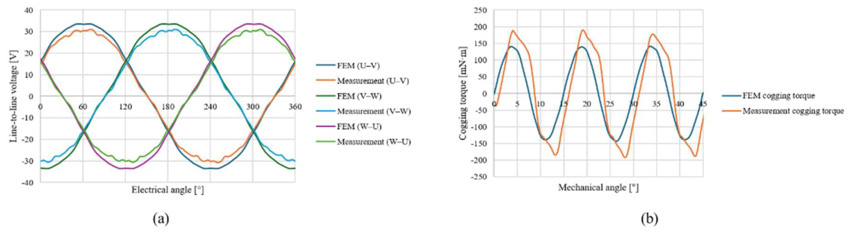
Figure 16.
Comparison of the calculated and measured surface magnetic flux-density waveforms along the rotor circumference after post-assembly magnetization.
Figure 16.
Comparison of the calculated and measured surface magnetic flux-density waveforms along the rotor circumference after post-assembly magnetization.
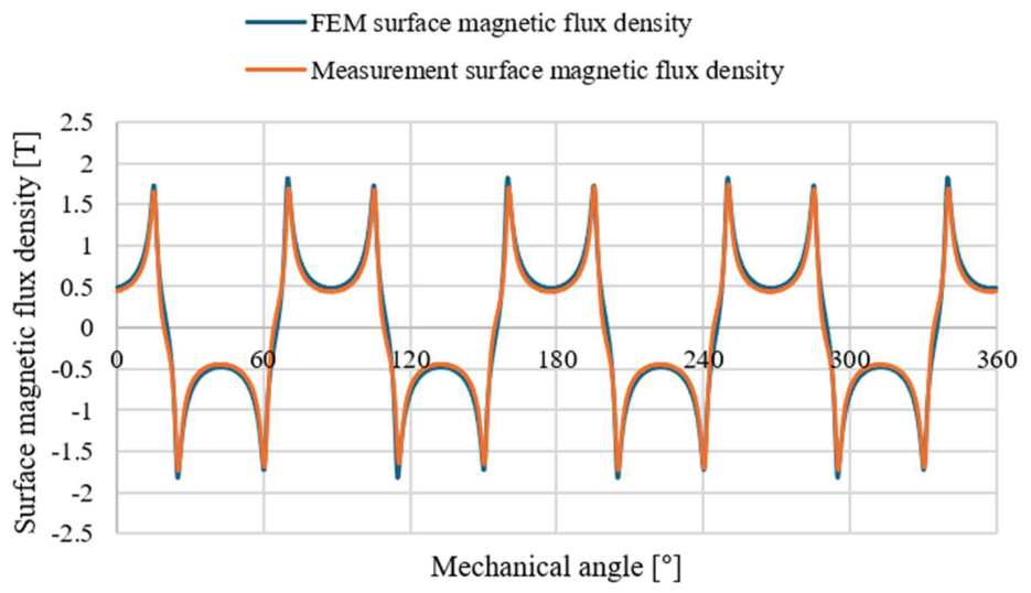
Figure 17.
Thermal saturation test results.
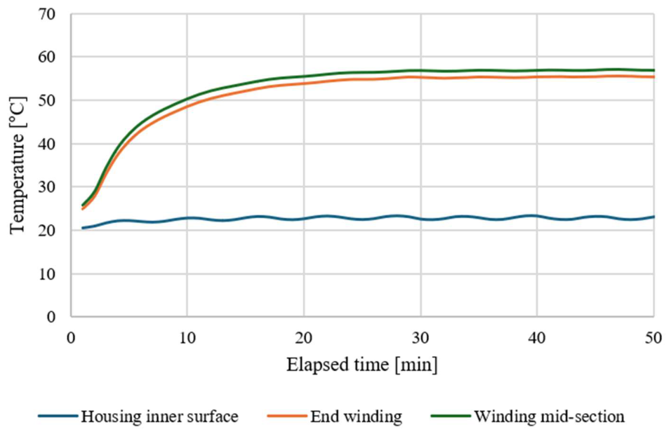
Table 2.
Main design requirements.
| Parameter | Requirement |
|---|---|
| Output power | ≥ 4 kW |
| Speed | 7000 rpm |
| Current density | ≤ 7 A/mm² |
| Irreversible demagnetization ratio | ≤ 3% |
| Post-assembly magnetization ratio | ≥ 97% |
| Load torque ripple | ≤ 10% |
Table 5.
Main performance changes throughout the integrated design procedure.
| Stage | Main modification | Output power [kW] | Current density [A/mm²] | Cogging torque [mN·m] | Load torque ripple [%] |
|---|---|---|---|---|---|
| Initial model | Baseline induction-motor envelope applied | 4.03 | 4.3 | 240 | 51.2 |
| Compact preliminary model | 65 mm stack; 41-turn preliminary winding | 4.67 | 6.8 | 570 | 45.7 |
| 2D optimized model | Rib-core skew and stator tooth-shoe chamfer optimized | 4.229 | 6.8 | 316 | 9.56 |
| Prototype test | Fabrication and experimental verification |
4.028 | 6.19 | 383.6 | Not measured |
Disclaimer/Publisher’s Note: The statements, opinions and data contained in all publications are solely those of the individual author(s) and contributor(s) and not of MDPI and/or the editor(s). MDPI and/or the editor(s) disclaim responsibility for any injury to people or property resulting from any ideas, methods, instructions or products referred to in the content. |
© 2026 by the authors. Licensee MDPI, Basel, Switzerland. This article is an open access article distributed under the terms and conditions of the Creative Commons Attribution (CC BY) license (http://creativecommons.org/licenses/by/4.0/).
Copyright: This open access article is published under a Creative Commons CC BY 4.0 license, which permit the free download, distribution, and reuse, provided that the author and preprint are cited in any reuse.


