
Submitted:
29 June 2026
Posted:
30 June 2026
You are already at the latest version
Abstract
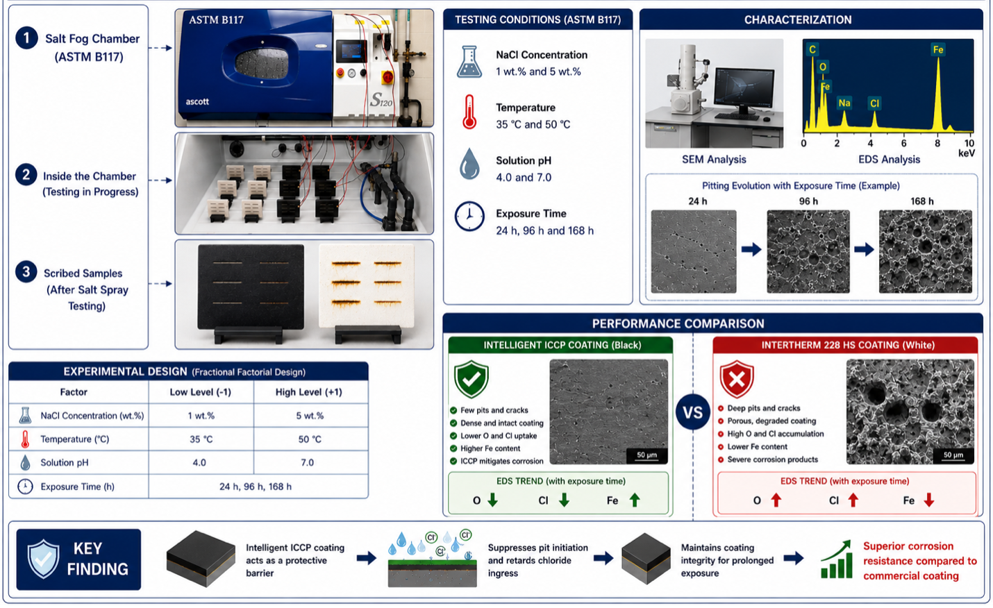
Corrosion of carbon steel in chloride-rich environments remains a critical challenge for marine and industrial applications, necessitating the development of durable protective coating systems. This study evaluates the corrosion resistance of an intelligent coating in comparison with the commercial coating Intertherm 228 HS under accelerated salt spray exposure following ASTM B117. Coated carbon steel specimens were subjected to 1 and 5 wt.% NaCl solutions at pH 4 and 7, temperatures of 35 and 50°C, and exposure durations of 24, 96, and 168 h. Corrosion behavior and coating degradation were characterized using scanning electron microscopy (SEM) and energy-dispersive spectroscopy (EDS). The results demonstrate that corrosion severity increases with chloride concentration, acidic conditions, elevated temperature, and prolonged exposure. SEM analysis revealed the progressive formation of pits, perforations, and corrosion products, while EDS showed increasing oxygen and chlorine contents accompanied by a decline in iron content, indicating accelerated coating deterioration and substrate corrosion. Compared with the commercial coating, the intelligent coating exhibited superior resistance to chloride-induced degradation, maintaining greater surface integrity and delaying corrosion propagation under all exposure conditions. These findings highlight the strong influence of environmental parameters on coating performance and demonstrate the potential of intelligent coatings to provide enhanced long-term corrosion protection for carbon steel structures operating in aggressive chloride-containing environments.
Keywords:
corrosion resistance
; salt spray testing (ASTM B117)
; protective intelligent coatings
; scanning electron microscopy
1. Introduction
Corrosion of metallic structures remains a significant challenge across many industrial sectors, particularly in environments where steel components are exposed to chloride ions, high humidity, and fluctuating temperatures [1,2,3]. Carbon steel and other ferrous alloys are widely used in infrastructure, marine applications, and energy systems due to their mechanical strength, low cost, and ease of fabrication [4,5]. However, their susceptibility to electrochemical degradation often limits long-term durability and structural reliability. In aggressive environments such as marine atmospheres or chloride-containing industrial settings, corrosion reactions can result in material loss, pit formation, surface degradation, and eventual structural failure. Consequently, improving corrosion resistance through advanced coatings and surface engineering technologies has become an important focus in corrosion science and materials engineering [6].
Protective coatings represent one of the most widely used strategies for mitigating corrosion of metallic substrates [7,8,9,10,11,12]. These coatings function primarily by isolating the underlying metal from corrosive species such as oxygen, moisture, and chloride ions. Depending on the coating chemistry and structure, protection may occur through barrier effects, inhibition of electrochemical reactions, or sacrificial protection mechanisms [13]. In chloride-rich environments, coatings must exhibit strong adhesion, low permeability to ionic species, and chemical stability to maintain protective performance during prolonged exposure. Numerous coating technologies have been developed to meet these requirements, including metallic coatings, polymeric barrier coatings, hybrid inorganic-organic coatings, and electrodeposited alloy films. The effectiveness of these coatings is influenced by factors such as composition, microstructure, adhesion strength, and resistance to environmental degradation [14].
Among the various corrosion protection approaches, alloy electrodeposition and advanced surface engineering techniques have received considerable attention [15,16]. According to Anwar et al. [10], electrodeposited zinc–nickel coatings provide superior corrosion protection compared with conventional zinc coatings due to their refined microstructure and enhanced barrier properties. Their studies demonstrated that optimizing deposition parameters and bath chemistry significantly improves coating performance by affecting phase composition, grain structure, and surface morphology. Specifically, optimization of zinc–nickel electrodeposition conditions has been shown to enhance corrosion resistance in saline environments, highlighting the critical role of process control in developing durable and reliable protective coatings [2,8,10,11,12,17].
In addition to metallic coatings, a range of organic and inorganic coating systems including epoxy-based and carbon-modified coatings have been developed to protect steel substrates from chloride-induced corrosion. Epoxy-based organic coatings, especially when formulated with corrosion inhibitors or nanofillers, form dense, adherent films that impede moisture and ion transport to the steel surface, significantly enhancing corrosion resistance in chloride environments [18]. Inorganic coatings such as ceramic oxides, phosphate layers, and sol-gel derived films offer thermally stable, densely packed barriers that reduce chloride diffusion and improve interface stability [19,20]. Carbon-based coatings (e.g., graphene and carbon nanotube-enhanced matrices) further improve barrier properties and mechanical integrity due to their high aspect ratio and impermeable structure, thereby limiting the transport of corrosive species [21,22]. Experimental studies combining these approaches demonstrate that optimized coatings systems can synergistically provide robust physical and chemical protection against chloride attack by restricting ion transport, enhancing adhesion, and stabilizing the coating–substrate interface [23].
Despite advances in coating technologies, corrosion protection remains strongly dependent on environmental conditions. Marine and salt-rich environments represent particularly aggressive settings for steel infrastructure because chloride ions promote localized corrosion and pitting. Experimental investigations of structural metals exposed to simulated marine environments have shown that corrosion behavior varies significantly depending on environmental chemistry, exposure duration, and material composition. These findings highlight the complexity of corrosion processes in chloride environments and emphasize the importance of systematic testing to evaluate coating performance under realistic service conditions [24,25].
One of the most widely adopted accelerated corrosion testing techniques is the salt spray (fog) test, standardized under ASTM B117-19 Standard Practice for Operating Salt Spray (Fog) Apparatus [26]. This test simulates aggressive chloride-rich conditions by exposing coated specimens to a continuous saline mist under controlled temperature and humidity conditions [27]. The ASTM B117 method has become a widely accepted standard for evaluating corrosion resistance of coatings and surface treatments. By accelerating the interaction between chloride ions and coated surfaces, the salt spray test enables researchers to assess coating durability within relatively short experimental periods while reproducing key aspects of marine and industrial atmospheric environments [26].
Recent developments in corrosion protection technologies have focused on intelligent or multifunctional coating systems capable of providing both protection and monitoring capabilities [28]. An intelligent coating system equipped with impressed current cathodic protection (ICCP) represents a promising approach for mitigating corrosion in harsh industrial environments [29]. Such coatings typically consist of an epoxy-based matrix combined with specialized additives and polyamine hardeners that enhance durability and corrosion resistance. In addition to acting as a barrier coating, the system incorporates sensing functionality that enables the digital detection and localization of coating damage [30]. When damage occurs, an electrical signal is generated and transmitted to an electronic controller, which identifies the affected area. The integrated ICCP system then provides protective current to the exposed metal surface, maintaining cathodic protection and limiting corrosion propagation. This combined sensing and protection approach is particularly relevant for infrastructure susceptible to corrosion under insulation (CUI), a common problem in oil and gas pipelines and processing facilities where moisture and chloride contaminants accumulate beneath insulation layers [29,31].
The objective of this study is to evaluate the corrosion resistance and protective performance of an intelligent epoxy-based coating system relative to a commercially available industrial coating under accelerated salt spray conditions using the ASTM B117 standard. Carbon steel samples were exposed to chloride environments with varying sodium chloride concentrations, temperatures, pH levels, and exposure durations. Surface characterization techniques, including SEM and EDS, were used to analyze corrosion products, elemental composition, and morphological changes occurring on the coated surfaces. Through this systematic investigation, the study aims to provide insights into the corrosion protection capabilities of advanced coating technologies and their potential application for mitigating corrosion in harsh industrial environments such as oil and gas infrastructure.
2. Experimental Methodology
2.1. Materials
Carbon steel plates with dimensions of 80 mm × 80 mm × 5 mm were used as the substrate material for all corrosion experiments. Two coating systems were evaluated. The first was an intelligent epoxy-based coating integrated with impressed current cathodic protection (ICCP) and the second was a commercially available high-performance epoxy coating, Intertherm 228 HS. Intelligent coatings represent an emerging class of multifunctional protective systems that combine conventional barrier protection with active corrosion mitigation and monitoring capabilities. These coatings are designed to isolate the metal substrate from aggressive environmental species while also enabling detection of coating degradation or mechanical damage during service. In ICCP-enabled intelligent coatings, electrical connectivity within the coating allows a controlled protective current to be applied to exposed metallic regions, which helps reduce corrosion propagation and maintain the integrity of the underlying steel. Such coatings are particularly attractive for industrial infrastructure operating in aggressive environments and are considered promising solutions for mitigating CUI in oil and gas pipelines and processing facilities. The purpose of this study was therefore to compare the corrosion protection performance of the intelligent coating system with that of the commercial coating under accelerated salt spray conditions. Sodium chloride (NaCl) used for the preparation of the salt solutions contained less than 0.3% total impurities. Sodium chloride containing anti-caking agents was not used because such additives may influence corrosion behaviour and act as corrosion inhibitors during the experiments.
2.2. Coating Application and Sample Preparation
Prior to coating, the carbon steel substrates were mechanically cleaned and prepared to remove any contaminants and surface oxides. The substrates were then divided into two groups. One group of samples was coated with Intertherm 228 HS according to the manufacturer’s recommended surface preparation and application procedures. The second group consisted of samples coated with the intelligent coating system, which was supplied pre-coated by the manufacturer. A total of 12 coated samples were prepared, consisting of six specimens for each coating system. Three replicate samples were used for each test condition to ensure experimental reliability and statistical reproducibility.
2.3. Salt Spray Corrosion Test
Accelerated corrosion tests were conducted using a salt spray chamber in accordance with ASTM B117-19: Standard Practice for Operating Salt Spray (Fog) Apparatus [26]. The chamber was operated under controlled temperatures of 35 °C and 50 °C. Salt spray solutions containing 1 wt.% and 5 wt.% NaCl were prepared using deionized water, and the solution pH was adjusted to 4.0 and 7.0 using a calibrated H2211 pH/ORP meter before each experiment. Approximately 30 L of solution was added to the chamber reservoir to provide a continuous supply for the 24 h exposure period, during which up to 25 L of solution was consumed. Before each test, the chamber was thoroughly cleaned by draining, rinsing, and drying the interior to eliminate residual deposits from previous experiments. The coated specimens were mounted in the specimen holder at an inclination of 15°–30° from the vertical and positioned to ensure uniform exposure to the salt fog, in accordance with ASTM B117 requirements. Salt fog exposure was maintained continuously for 24 h. After each exposure cycle, the specimens were removed, gently rinsed with water not exceeding 38 °C to remove residual salt deposits, immediately dried, and subsequently evaluated. Figure 1 presents the experimental setup, including the ASTM B117 salt spray chamber, the arrangement of coated specimens during testing, and representative scribed specimens after exposure. The post-test images qualitatively illustrate corrosion development along the intentional scribe and provide a visual comparison of the corrosion protection performance of the intelligent coating and the commercial epoxy coating.
2.4. Corrosion Evaluation
Following exposure, the coated samples were examined by visual inspection to identify signs of coating degradation, pitting corrosion, or general corrosion damage. The observations were recorded in accordance with the reporting guidelines specified in Section 15 of ASTM B117-19. If no significant changes were observed between the pre- and post-exposure conditions, additional experiments with longer exposure durations were conducted to further evaluate coating performance.
2.5. Experimental Design and Statistical Analysis
The experimental design was conducted using Minitab Statistical Software (Version 21.1.0). A two-level fractional factorial design (FFD) was implemented to systematically evaluate the effects of key environmental parameters on the corrosion performance of the coating systems. Three independent variables were considered in the experimental design:
- NaCl concentration
- Solution pH
- Chamber temperature
Each factor was evaluated at two levels, coded as -1 (low level) and 1 (high level). The selected operating conditions were:
- NaCl concentration: 1 wt.% (-1) and 5 wt.% (+1)
- Temperature: 35 °C (-1) and 50 °C (+1)
- Solution pH: 4.0 (-1) and 7.0 (+1)
The experimental matrix consisted of 12 runs with three replications, corresponding to a resolution III fractional factorial design. Exposure durations of 24, 96, and 168 h were also investigated to examine the time-dependent corrosion behaviour of the coatings.
In total, 24 coated samples were evaluated, including 12 intelligent coated specimens and 12 Intertherm 228 HS-coated specimens. The factorial design allowed systematic assessment of the environmental factors influencing coating degradation while enabling comparison of the corrosion resistance performance of the two coating systems.

| Variable | Type | Level | Measurement (Dependent Variables) |
|---|---|---|---|
| Temperature (°C) | Independent | 35 °C and 50 °C | Visual Inspection (intelligent coating vs. commercial) |
| pH of the solution | Independent | 4.0 and 7.0 | |
| NaCl Conc. (wt.%) | Independent | 1 wt.% and 5 wt.% |
Table 2.
Factors and levels for the two-level FFD design (ASTM B117-19).
| Factors | Levels | ||
|---|---|---|---|
| -1 | 1 | ||
| P | NaCl concentration (wt.%) | 01 | 05 |
| Q | Temperature of the pipe (˚C) | 35 | 50 |
| R | pH of the solution | 4.0 | 7.0 |
3. Results and Discussion
3.1. SEM and EDS Analysis of Scribed Intelligent and Intertherm 228 HS Coated Samples
The microstructural morphology and elemental composition of the scribed intelligent and Intertherm 228 HS coated samples were characterized using a FEI MLA650F scanning electron microscope (SEM) equipped with an energy-dispersive spectroscopy (EDS) detector. To prepare the samples for microscopic analysis, the samples were cleaned, sandblasted, and subsequently polished, followed by a standard grinding/polishing sample preparation procedure for carbon steel plates.
Scribed intelligent and Intertherm 228 HS coated samples were exposed to a range of NaCl concentrations, temperatures, and pH values. Representative optical images are presented in Figure 2 for the scribed intelligent and Intertherm 228 HS coated samples. The intelligent and Intertherm 228 HS samples were inspected visually, and Figure 2 clearly shows that that the intelligent coating is protected from corrosion by a dual protection mechanism [32,33], including the coating and the ICCP. However, the Intertherm 228 HS samples exhibited severe corrosion. The intelligent sample exposed to the salt chamber at 1.0 wt.% NaCl solution, 35 °C and 7.0 pH for 24, 96, and 168 hours did not show corrosion on the scribed section. However, Intertherm 228HS samples had extensive corrosion on the scribed section. The intelligent coating provides superior corrosion protection base metal against corrosion.
All SEM micrographs were acquired at the same magnification, while the inset images show higher-magnification views of the selected regions highlighted by the red boxes. In which small pits/cracks are magnified for further understanding as shown by the red color in the images. Figure 3 presents SEM micrographs of the intelligent coating after exposure to 1 wt.% NaCl at 35 °C and pH 7 for 24, 96, and 168 h. No significant corrosion features, such as pitting or coating delamination, were observed throughout the exposure period. The irregular surface morphology primarily resulted from the intentional scribing process rather than corrosion damage. With increasing exposure time, minor salt deposits accumulated on the coating surface, partially filling the scribed region without initiating localized corrosion.
An EDS analysis detected carbon contents on the intelligent coatings. This is because the main composition of the intelligent coating primarily consists of carbon-based constituents. As seen in Table 1, the intelligent coated samples exposed to 1.0 wt.% NaCl solution at 35 °C and pH 7.0 contained carbon and oxygen for 24 hours, 96 hours, and 168 hours. The carbon and oxygen contents gradually decreased with increasing exposure time, whereas the relative iron content increased due to progressive thinning of the coating layer and increased interaction between the electron beam and the underlying steel substrate.
Table 1.
EDS analysis of intelligent coated samples exposed at 1.0 wt.% of NaCl solution, temperature of the SFC is at 35 °C and pH of the solution is at 7.0, (a) 24 hours, (b) 96 hours, and (c) 168 hours.
Table 1.
EDS analysis of intelligent coated samples exposed at 1.0 wt.% of NaCl solution, temperature of the SFC is at 35 °C and pH of the solution is at 7.0, (a) 24 hours, (b) 96 hours, and (c) 168 hours.
| Elements (wt.%) |
Carbon (C) |
Oxygen (O) |
Sodium (Na) |
Chlorine (Cl) |
Iron (Fe) |
|---|---|---|---|---|---|
| Exposed at 24 hours | 12.47 | 10.51 | 0.062 | 0.077 | 76.86 |
| Exposed at 96 hours | 11.78 | 8.55 | 1.10 | 0.04 | 78.53 |
| Exposed at 168 hours | 10.51 | 7.19 | 0.10 | 0.03 | 82.17 |
EDS analysis was also performed on Intertherm 228 HS-coated samples before and after removal of corrosion products. In this case, the carbon, oxygen, sodium, and chlorine content are negligible, which leads to a higher Fe content. The Fe content was higher in the sample exposed for 24 h than in the sample exposed for 168 h.
A similar carbon and oxygen composition was observed in the Intertherm 228 HS coated samples exposed to 1.0 wt.% NaCl solution at 35 °C and pH 7.0 for 24 hours, 96 hours, and 168 hours with corrosion products (Table 2). The sample exposed at 24 hours of exposure time has 9.22 wt.% carbon and 21.09 wt.% oxygen content. As the exposure period increases, the carbon and oxygen contents decrease (5.42 wt.% and 7.02 wt.%) at 96 hours and again increase (12.41 wt.% and 30.93 wt.%) at 168 hours. The lower oxygen content at 96 h may indicate the temporary formation of a relatively compact corrosion layer. However, after 168 h, the increase in oxygen content suggests further oxidation and deterioration of the protective layer. The samples at higher exposure (168 hours) to a salt fog chamber led to enhanced corrosion, indicating that the passive layer formed at 96 hours was broken down, resulting in enhanced corrosion and increased carbon and oxygen contents with a reduction in base metal composition.
Table 2.
EDS analysis of Intertherm 228 HS coated samples exposed at 1.0 wt.% of NaCl solution, temperature of the SFC is at 35 °C and pH of the solution is at 7.0, (a) 24 hours, (b) 96 hours, and (c) 168 hours with and without corrosion products.
Table 2.
EDS analysis of Intertherm 228 HS coated samples exposed at 1.0 wt.% of NaCl solution, temperature of the SFC is at 35 °C and pH of the solution is at 7.0, (a) 24 hours, (b) 96 hours, and (c) 168 hours with and without corrosion products.
| Elements (wt.%) |
Carbon (C) |
Oxygen (O) |
Sodium (Na) |
Chlorine (Cl) |
Iron (Fe) |
|---|---|---|---|---|---|
|
Exposed at 24 hours (Without corrosion products) |
2.52 | 0.60 | 0.05 | 0.04 | 96.79 |
|
Exposed at 24 hours (With corrosion products) |
9.22 | 21.09 | 1.92 | 1.80 | 65.97 |
|
Exposed at 96 hours (Without corrosion products) |
2.03 | 1.25 | 0.10 | 0.08 | 96.54 |
|
Exposed at 96 hours (With corrosion products) |
5.42 | 7.02 | 4.14 | 13.29 | 70.13 |
|
Exposed at 168 hours (Without corrosion products) |
2.78 | 1.49 | 0.00 | 0.79 | 94.92 |
|
Exposed at 168 hours (With corrosion products) |
12.41 | 30.93 | 0.57 | 0.87 | 55.22 |
Figure 4 shows SEM images of Intertherm 228 HS coated samples exposed to 1.0 wt.% NaCl solution for 24 hours, 96 hours, and 168 hours at 35 °C with and without corrosion products. As shown in Figure 4 (a), (b), and (c), the samples were exposed to the salt chamber and were examined after carefully removing the corrosion products. It is observed that as the exposure period of the samples increases, it leads to an increase in pit density, diameter, and depth, and the pit density increased with exposure time. Figure 4 (a1), (a2), and (a3) samples exposed to the salt chamber with corrosion products. Figure 4 (a1) reveals corroded samples that exhibit a porous corrosion product with a cloud-like morphology. The higher magnification SEM images in the inset show a white cloudy texture on the corroded section. A longer exposure period (Figure 4 (a2) and (a3)) increased the number and size of pits/pits of the surfaces of the corroded samples, and the porous corrosion products with a cauliflower-like morphology on the corroded surface. Moreover, the samples exposed at 168 hours show extensive and bigger pits with a cloudy appearance on the samples (Figure 4(a3)).
Figure 5 shows a visual inspection of the scribed intelligent and Intertherm 228 HS coated samples. As can be seen in Figure 5, the intelligent coating in the scribed section of the sample showed some corrosion. The Intertherm 228 HS coating did not show corrosion. According to the results of the design of experiments, samples exposed to 1.0 wt.% NaCl solution at 50 °C and pH 4.0 for 24, 96, and 168 hours showed higher corrosion rates in comparison to the other settings. A localized blistering is also visible on the coated samples. In addition, Intertherm 228 HS samples showed extensive corrosion on the scribed section.
The intelligent coated samples exposed to 1.0 wt.% NaCl solution at 50 °C and pH at 4.0 exhibited corrosion signs, as illustrated in Figure 6. It is observed from Figure 6 (b) that microcrack formation became evident after 96 h. In addition, at higher exposure times (168 hours) the intelligent samples presented non-uniformity and a porous surface, and the the crack propagated further with increasing exposure time. It is observed from the magnified section the color image that showed large cracks.
An EDS analysis was performed on the intelligent coatings to detect carbon, oxygen, and sodium. Carbon is the dominant component of intelligent coatings, and oxygen and sodium are detected in salt fog chambers when the coatings are exposed to saline solution. As shown in Table 3, intelligent coated samples exposed to 1.0 wt.% NaCl solution at 50 °C and pH 4.0 for 24 hours, 96 hours, and 168 hours contained carbon, oxygen, and sodium. A decrease in carbon content and an increase in oxygen and sodium content occurred as exposure time increased. Since the saline solution damages, the intelligent coated samples, the corrosion-resistant properties of the coated samples are reduced. Increased exposure time also reduces the strength of the coated samples.
Table 3.
EDS analysis of intelligent coated samples exposed at 1.0 wt.% of NaCl solution, temperature of the SFC is at 50 °C and pH of the solution is at 4.0, (a) 24 hours, (b) 96 hours, and (c) 168 hours.
Table 3.
EDS analysis of intelligent coated samples exposed at 1.0 wt.% of NaCl solution, temperature of the SFC is at 50 °C and pH of the solution is at 4.0, (a) 24 hours, (b) 96 hours, and (c) 168 hours.
| Elements (wt.%) |
Carbon (C) |
Oxygen (O) |
Sodium (Na) |
Chlorine (Cl) |
Iron (Fe) |
|---|---|---|---|---|---|
| Exposed at 24 hours | 6.60 | 4.37 | 1.55 | 0.01 | 87.43 |
| Exposed at 96 hours | 8.52 | 4.29 | 1.17 | 0.01 | 85.98 |
| Exposed at 168 hours | 6.96 | 9.00 | 2.54 | 0.49 | 80.96 |
A study was conducted using EDS on Intertherm 228 HS coated samples exposed to 1.0 wt.% NaCl solution for 24 hours, 96 hours, and 168 hours without corrosion products (Table 4). In this case, the carbon, oxygen, sodium, and chlorine content are detectable. The carbon and oxygen contents of the samples appear after the corrosion products have been removed. The Intertherm 228 HS coated samples contain a significantly higher percentage of carbon and oxygen after 24 and 168 hours of exposure than samples exposed after 96 hours. Thus, after removing the corrosion product, the sample showed corrosion behavior or oxidation, resulting in enhanced corrosion rates.
A similar carbon, oxygen, sodium, and chlorine composition was observed in the Intertherm 228 HS coated samples exposed to 1.0 wt.% of NaCl solution, the temperature at 50 °C and pH of the solution at 4.0 for 24 hours, 96 hours, and 168 hours with corrosion products (Table 4). At 24 hours of exposure, the sample contains 13.90 wt.% carbon, 31.92 wt.% oxygen, 8.22 wt.% sodium, and 0.50 wt.% chlorine. As the exposure period increases, the chlorine contents increase rapidly (12.83 wt.%) at 96 hours and again increase (16.64 wt.%) at 168 hours. The progressive increase in oxygen and chlorine contents indicates accelerated oxide formation and chloride accumulation, confirming the increased severity of corrosion under acidic conditions.
Table 4.
EDS analysis of Intertherm 228 HS coated samples exposed at 1.0 wt.% of NaCl solution, temperature of the SFC is at 50 °C and pH of the solution is at 4.0, (a) 24 hours, (b) 96 hours, and (c) 168 hours with and without corrosion products.
Table 4.
EDS analysis of Intertherm 228 HS coated samples exposed at 1.0 wt.% of NaCl solution, temperature of the SFC is at 50 °C and pH of the solution is at 4.0, (a) 24 hours, (b) 96 hours, and (c) 168 hours with and without corrosion products.
| Elements (wt.%) |
Carbon (C) |
Oxygen (O) |
Sodium (Na) |
Chlorine (Cl) |
Iron (Fe) |
|---|---|---|---|---|---|
|
Exposed at 24 hours (Without corrosion products) |
10.54 | 19.24 | 0.10 | 0.52 | 69.60 |
|
Exposed at 24 hours (With corrosion products) |
13.90 | 31.92 | 8.22 | 0.50 | 45.46 |
|
Exposed at 96 hours (Without corrosion products) |
9.42 | 16.71 | 0.08 | 2.58 | 71.15 |
|
Exposed at 96 hours (With corrosion products) |
15.26 | 24.93 | 13.08 | 12.83 | 33.85 |
|
Exposed at 168 hours (Without corrosion products) |
11.34 | 21.82 | 0.13 | 1.82 | 64.88 |
|
Exposed at 168 hours (With corrosion products) |
15.96 | 29.23 | 11.74 | 16.64 | 26.31 |
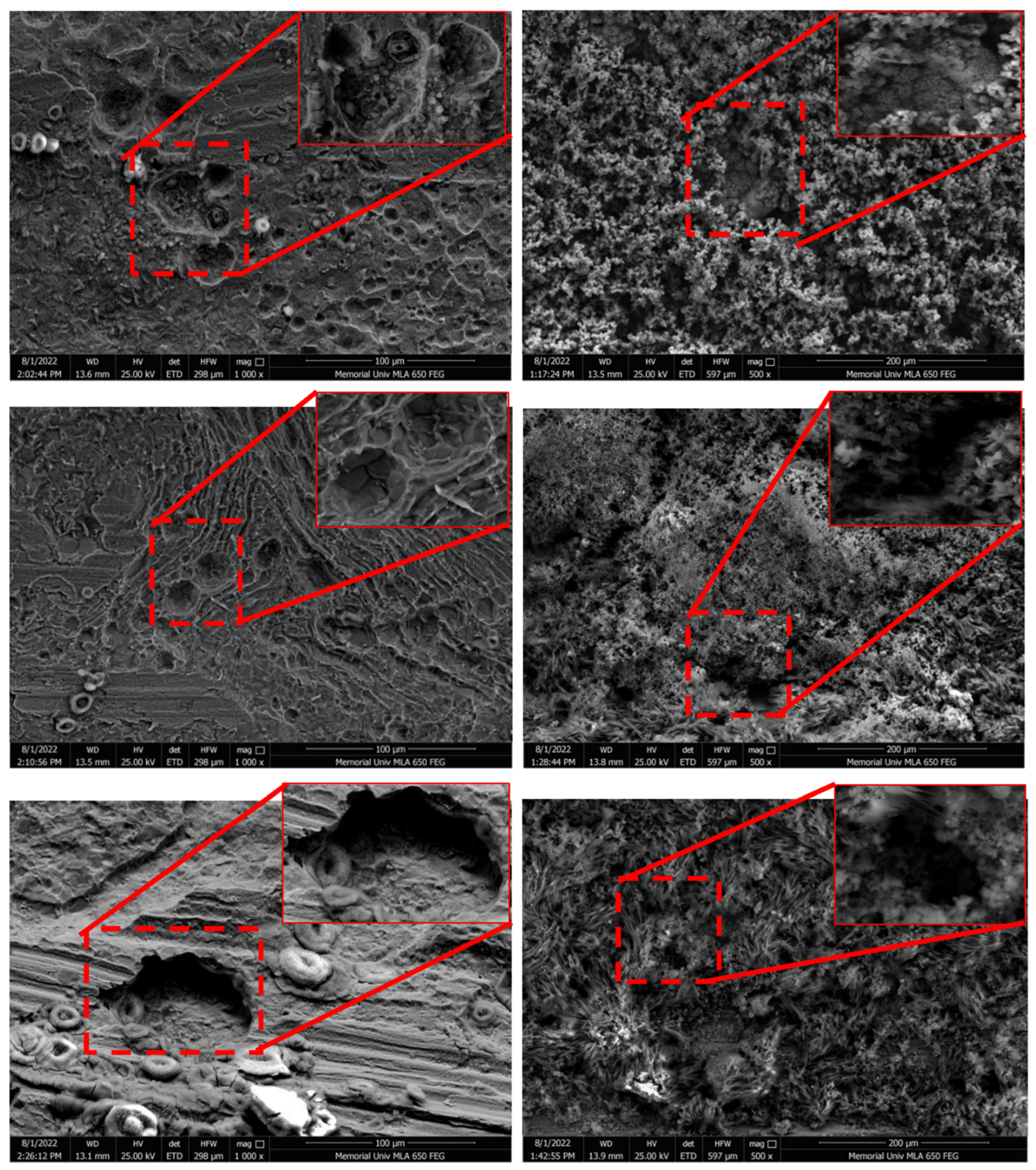
Figure 7 shows SEM images of Intertherm 228 HS coated samples exposed to 1.0 wt.% of NaCl solution, temperature is at 50 °C and pH of the solution is at 4.0 for 24 hours, 96 hours, and 168 hours with and without corrosion products. As shown in Figure 7 (a), (b), and (c), the samples were exposed to the salt chamber and scanned it with removing the corrosion products. It is observed that as the exposure period of the samples increases, it leads to appear the swollen corrosion nodules on the corroded surface. At higher exposure time the swollen textured surface start showing the crack and that lead to degrade the structural integrity of the coating of the base material. Figure 7 (a1), (a2), and (a3) samples exposed to the salt chamber and scanned with corrosion products. Figure 7 (a1) reveals corroded samples that exhibit a grey cloudy precipitated appearance. The higher magnification SEM images in the inset show a grey cloudy texture on the corroded section led to show a round pit. A longer exposure period (Figure 7 (a2) and (a3)) enhanced the perforations/pits of the surfaces of the corroded samples, and the grey cloudy materials appeared on the corroded surface. Moreover, the samples exposed at 168 hours show extensive and bigger pits with a cloudy appearance on the samples (Figure 7(a3)).
Figure 8 illustrates a visual inspection of intelligent and Intertherm 228 HS coated samples. It is apparent from Figure 8 that the intelligent coating on the scribed section of the sample exhibits localized corrosion, as does the Intertherm 228 HS coating. Corrosion is also visible in SEM images of the intelligent sample. Specifically, the samples exposed to 5.0 wt.% of NaCl solution for 24, 96, and 168 hours at 50 °C, pH 7.0, and the temperature of the SFC resulted in higher corrosion rates. Moreover, Intertherm 228HS samples also showed severe localized corrosion on the scribed section.
As shown in Figure 9, intelligent coated samples exposed to 5.0 wt.% of NaCl solution at 50 °C and a pH of 7.0 showed some corrosion signs. A crack appears on the intelligent samples after 24 hours of appearing as shown in Figure 9 (a). The crack may have originated from pre-existing coating defects introduced during manufacturing or sample preparation. Further, at higher exposure times (168 hours), the intelligent samples showed non-uniformity and porous textures on the surface, increasing the crack depth (Figure 9 (c)). It is observed from the magnified section of the images in red ccolor that showed large cracks.
EDS analysis revealed that the intelligent coatings contained carbon, oxygen, and sodium. Carbon is the main component of C intelligent coatings, and when exposed to saline solution in the salt fog chamber, oxygen and sodium can be detected. Table 5 shows that intelligent coated samples exposed to 5.0 wt.% NaCl solution at 50 °C and pH of 7.0 for 24 hours, 96 hours, and 168 hours contained carbon, oxygen, and sodium contents. As exposure time increased, the carbon, oxygen and sodium contents increased. It is observed that the appearance of the saline solution on the intelligent coated samples induced coating degradation on the coated samples that led to reduce the corrosion resistant properties of the coated samples. As a result, as exposure time increases, the strength of the intelligent coated samples is reduced as well.
Table 5.
EDS analysis of intelligent coated samples exposed at 5.0 wt.% of NaCl solution, temperature of the SFC is at 50 °C and pH of the solution is at 7.0, (a) 24 hours, (b) 96 hours, and (c) 168 hours.
Table 5.
EDS analysis of intelligent coated samples exposed at 5.0 wt.% of NaCl solution, temperature of the SFC is at 50 °C and pH of the solution is at 7.0, (a) 24 hours, (b) 96 hours, and (c) 168 hours.
| Elements (wt.%) |
Carbon (C) |
Oxygen (O) |
Sodium (Na) |
Chlorine (Cl) |
Iron (Fe) |
|---|---|---|---|---|---|
| Exposed at 24 hours | 4.92 | 1.59 | 0.35 | 0.03 | 93.08 |
| Exposed at 96 hours | 5.03 | 4.78 | 19.82 | 0.08 | 70.80 |
| Exposed at 168 hours | 27.46 | 10.70 | 17.24 | 0.06 | 44.45 |
A study of Intertherm 228 HS coated samples exposed to 5.0 wt.% of NaCl solution, temperature of the SFC is at 50 °C and pH of the solution is at 7.0 for 24 hours, 96 hours, and 168 hours without corrosion products (Table 6) was conducted using EDS. In this case, the oxygen, and sodium content are detectable. It means that after removing the corrosion products on the samples, having appearance of the oxygen and sodium contents. As the exposure time increases, led to enhance the amount of oxygen and sodium contents in the Intertherm 228 HS coated samples. As a result, the the samples exhibited progressive oxidation and corrosion degradation or oxidation after removing the corrosion product that led to enhance the corrosion rate of the base metal.
An oxygen, sodium, and chlorine composition were observed in the Intertherm 228 HS coated samples exposed to 5.0 wt.% of NaCl solution, temperature of the SFC is at 50 °C and pH of the solution is at 7.0 for 24 hours, 96 hours, and 168 hours with corrosion products (Table 6). The sample exposed at 24 hours of exposure time has 2.23 wt.% oxygen content. As the exposure period increases, the oxygen contents increase rapidly (15.69 wt.%) at 96 hours and again increase (27.43 wt.%) at 168 hours. The samples at higher exposure (168 hours) to a salt fog chamber led to enhanced corrosion rate due to the appearance of the enormous amount of 27.23 wt.% oxygen and 3.36 wt.% of chlorine contents, resulting in enhanced corrosion rate with a reduction in base metal composition.
Table 6.
EDS analysis of Intertherm 228 HS coated samples exposed at 5.0 wt.% of NaCl solution, temperature of the SFC is at 50 °C and pH of the solution is at 7.0, (a) 24 hours, (b) 96 hours, and (c) 168 hours with and without corrosion products.
Table 6.
EDS analysis of Intertherm 228 HS coated samples exposed at 5.0 wt.% of NaCl solution, temperature of the SFC is at 50 °C and pH of the solution is at 7.0, (a) 24 hours, (b) 96 hours, and (c) 168 hours with and without corrosion products.
| Elements (wt.%) |
Carbon (C) |
Oxygen (O) |
Sodium (Na) |
Chlorine (Cl) |
Iron (Fe) |
|---|---|---|---|---|---|
|
Exposed at 24 hours (Without corrosion products) |
0.00 | 1.86 | 0.50 | 0.00 | 97.56 |
|
Exposed at 24 hours (With corrosion products) |
0.00 | 2.23 | 0.08 | 0.38 | 95.95 |
|
Exposed at 96 hours (Without corrosion products) |
0.00 | 1.42 | 0.62 | 0.03 | 97.88 |
|
Exposed at 96 hours (With corrosion products) |
3.45 | 15.69 | 0.84 | 1.05 | 78.88 |
|
Exposed at 168 hours (Without corrosion products) |
0.00 | 2.32 | 0.40 | 0.62 | 96.07 |
|
Exposed at 168 hours (With corrosion products) |
0.74 | 27.43 | 0.53 | 3.36 | 67.83 |
Figure 10 shows SEM images of Intertherm 228 HS coated samples exposed to 5.0 wt.% of NaCl solution, temperature of the SFC is at 50 °C and pH of the solution is at 7.0 for 24 hours, 96 hours, and 168 hours with and without corrosion products. As shown in Figure 10 (a), (b), and (c), the samples were exposed to the salt chamber and scanned it with removing the corrosion products. It is evident that the localized pits initiated on the manufacturing defects of the scribed section. The exposure period of the samples increases it leads to appear to broaden the pit depth and diameter on the corroded surface. At higher exposure time (168 hours) the pit start deepened the textured that lead to loosen the strength of the base material. Figure 10 (a1), (a2), and (a3) samples exposed to the salt chamber and scanned with corrosion products. Figure 10 (a1) reveals corroded samples that exhibit a grey cloudy precipitated appearance. The higher magnification SEM images in the inset show a grey cloudy texture on the corroded section led to show a round pit. A longer exposure period (Figure 10 (a2) and (a3)) enhanced the perforations/pits of the surfaces of the corroded samples, and the grey cloudy materials appeared on the corroded surface. Moreover, the samples exposed at 168 hours show huge and bigger pits, but the pits are covered with the cloudy surface on the samples (Figure 10 (a3)).
Figure 11 shows a visual inspection of intelligent coated samples and Intertherm 228 HS coated samples. An intelligent and Intertherm 228 HS samples were visually inspected, and it is evident from Figure 11 that the intelligent coating exhibited corrosion in the scribed section. SEM images also reveal corrosion in the intelligent sample. Thus, the samples exposed in NaCl solutions at 5% for 24 hours, 96 hours, and 168 hours at 35 °C and pH 4.0 for 24 hours, 96 hours, and 168 hours showed higher corrosion in comparison with other experimental designs. As a result of the higher NaCl solution and acidic environment in the salt fog chamber, both coated samples were significantly more corroded. A large amount of corrosion was also present on the scribed section of Intertherm 228HS samples.
Figure 12 presents the SEM micrographs of the intelligent coating exposed to 5.0 wt.% NaCl solution at an SFC temperature of 35 °C and a solution pH of 4.0 for 24, 96, and 168 h. Severe surface degradation was observed throughout the exposure period. After 24 h (Figure 12a), numerous localized pits were already present on the coating surface, indicating the initiation of corrosion under the combined effects of a high chloride concentration and acidic environment. As the exposure time increased to 96 and 168 h, both the density and dimensions of the pits progressively increased, accompanied by pronounced surface roughening and non-uniform morphology. The higher-magnification inset images further reveal the growth and coalescence of localized pits, confirming the progressive deterioration of the coating with prolonged exposure.
An EDS analysis of the intelligent coatings revealed the presence of carbon, oxygen, and chlorine. Since intelligent coatings contain carbon, exposure to saline solution in the salt fog chamber revealed oxygen and chlorine contents. Table 7 shows that the intelligent coated samples exposed to 5.0 wt.% of NaCl solution at 35 °C and pH 4.0 have carbon, oxygen, and chlorine contents for 24 hours, 96 hours, and 168 hours. As exposure time increased, the carbon, oxygen, and chlorine contents increased. The chemical composition of carbon, oxygen, and chlorine in the intelligent coated sample is found to be lower than in the other design of the experiment setting, resulting in a less corrosion-prone sample. As a result, as exposure time increases, the strength of the intelligent coated samples is retained as well due to a larger amount of base metal composition.
Table 7.
EDS analysis of intelligent coated samples exposed at 5.0 wt.% of NaCl solution, temperature of the SFC is at 35 °C and pH of the solution is at 4.0, (a) 24 hours, (b) 96 hours, and (c) 168 hours.
Table 7.
EDS analysis of intelligent coated samples exposed at 5.0 wt.% of NaCl solution, temperature of the SFC is at 35 °C and pH of the solution is at 4.0, (a) 24 hours, (b) 96 hours, and (c) 168 hours.
| Elements (wt.%) |
Carbon (C) |
Oxygen (O) |
Sodium (Na) |
Chlorine (Cl) |
Iron (Fe) |
|---|---|---|---|---|---|
| Exposed at 24 hours | 3.44 | 0.06 | 0.02 | 0.37 | 96.12 |
| Exposed at 96 hours | 5.90 | 0.87 | 0.00 | 0.66 | 92.57 |
| Exposed at 168 hours | 6.76 | 2.10 | 0.05 | 0.31 | 90.78 |
EDS analysis was conducted on Intertherm 228 HS coated samples exposed to 5.0 wt.% NaCl solution at 35 °C, 4.0 pH, and 5.0 temperature for 24 hours, 96 hours, and 168 hours without corrosion products (Table 8). Carbon and oxygen content are detected in this case. In other words, after removing corrosion products from the samples, the carbon and oxygen contents appear in significantly higher amounts. The carbon and oxygen contents of the Intertherm 228 HS coated samples increase with increasing exposure time. After removing the corrosion product, the sample displayed corrosion behavior or oxidation, which increased the corrosion rate of the base metal.
Intertherm 228 HS coated samples exposed to 5.0 wt.% NaCl solution at 35 °C, pH 4.0, and SFC temperature at 35 °C was found to have oxygen, sodium, and chlorine composition for 24 hours, 96 hours, and 168 hours, respectively (Table 8). At 24 hours of exposure, the sample contains 4.36 wt.% carbon and 20.23 wt.% oxygen. As the exposure period increases, the oxygen contents remain consistent (21.68 wt.%) at 96 hours and again increase (21.32 wt.%) at 168 hours. The samples exposed to the salt fog chamber for 168 hours showed an enhanced corrosion rate due to the presence of oxygen contents of 21.32 wt.%. This resulted in an enhanced corrosion rate and a reduction in the composition of the base metal.
Table 8.
EDS analysis of Intertherm 228 HS coated samples exposed at 5.0 wt.% of NaCl solution, temperature of the SFC is at 35 °C and pH of the solution is at 4.0, (a) 24 hours, (b) 96 hours, and (c) 168 hours with and without corrosion products.
Table 8.
EDS analysis of Intertherm 228 HS coated samples exposed at 5.0 wt.% of NaCl solution, temperature of the SFC is at 35 °C and pH of the solution is at 4.0, (a) 24 hours, (b) 96 hours, and (c) 168 hours with and without corrosion products.
| Elements (wt.%) |
Carbon (C) |
Oxygen (O) |
Sodium (Na) |
Chlorine (Cl) |
Iron (Fe) |
|---|---|---|---|---|---|
|
Exposed at 24 hours (Without corrosion products) |
1.05 | 3.09 | 0.17 | 0.04 | 95.64 |
|
Exposed at 24 hours (With corrosion products) |
4.36 | 20.23 | 0.28 | 0.90 | 74.20 |
|
Exposed at 96 hours (Without corrosion products) |
2.43 | 3.56 | 0.44 | 0.04 | 93.54 |
|
Exposed at 96 hours (With corrosion products) |
4.84 | 21.68 | 0.17 | 2.89 | 70.42 |
|
Exposed at 168 hours (Without corrosion products) |
20.53 | 6.12 | 0.19 | 0.07 | 73.08 |
|
Exposed at 168 hours (With corrosion products) |
4.03 | 21.32 | 4.85 | 3.42 | 66.38 |
As shown in Figure 13, SEM images of Intertherm 228 HS coated samples with and without corrosion products were exposed to NaCl solution at 5.0 wt.% for 24 hours, 96 hours, and 168 hours at 35 °C and 4.0 pH. In Figure 13 (a), (b), and (c), the samples were exposed to a salt chamber and examined after carefully removing corrosion products. As the exposure period for the samples increases, deeper and wider pits are observed, and the number of pits increases. Figure 13 (a1), (a2), and (a3) samples exposed to the salt chamber scanned with corrosion products. Figure 13 (a1) reveals corroded samples that exhibit a non-uniform surface with a cloudy perforated appearance. An inset SEM image shows a cloudy texture on the corroded section at higher magnifications. As a result of a longer exposure period (Figure 13 (a2) and (a3)), the thin perforations/pits on the surface of the corroded samples increased, and cloudy materials appeared on the surface. Moreover, the samples exposed at 168 hours show huge and bigger pits with a cloudy appearance on the samples (Figure 13 (a3)).
4. Conclusions
The corrosion behaviour of coated carbon steel substrates was investigated using a FFD under accelerated salt spray conditions in accordance with ASTM B117-19. The experimental results demonstrated that environmental factors, including NaCl concentration, solution pH, temperature, and exposure duration, significantly influence the corrosion performance of the coating systems. Among the tested conditions, the most severe corrosion environment occurred at 1 wt.% NaCl concentration, 50 °C, and pH 4.0, where samples exposed for 24, 96, and 168 h exhibited the highest corrosion susceptibility. Elemental analysis of the intelligent coated samples confirmed the presence of carbon as the primary component of the coating matrix, while exposure to the salt fog environment resulted in the detection of oxygen and sodium, indicating the formation of corrosion products and interaction with the saline environment. For the Intertherm 228 HS-coated samples, EDS analysis revealed a progressive increase in chlorine concentration with exposure time, reaching 12.83 wt.% at 96 h and 16.64 wt.% at 168 h, accompanied by an increase in oxygen content to approximately 29.23 wt.%, suggesting chloride-assisted localized corrosion and oxide formation that contributed to the reduction of iron content in the substrate. SEM observations further confirmed progressive surface degradation, showing swollen circular features, localized pitting, and grey cloudy corrosion products that became more pronounced with increasing exposure time, particularly after 168 h of exposure. These results indicate that acidic conditions (pH 4.0) combined with elevated temperature (50 °C) significantly accelerate corrosion processes in saline environments. The findings are particularly relevant to CUI in oil and gas pipelines, where carbon steel components are frequently exposed to moisture, chloride-containing environments, and elevated operating temperatures beneath insulation systems, which can lead to subsurface corrosion damage and potential structural failure. Overall, the study demonstrates that environmental severity and exposure duration play critical roles in degradation of coating integrity, and the applied FFD approach provides a systematic framework for evaluating the corrosion resistance of protective coatings intended for harsh industrial environments.
Funding
This research received no external funding.
Data Availability Statement
The original contributions presented in this study are included in the article. Further inquiries can be directed to the corresponding author.
Conflicts of Interest
The authors declare no conflict of interest.
References
- Wang, M.; et al. Research on marine atmospheric corrosion behavior of carbon steel during Western Pacific voyage. J. Mater. Res. Technol. 2025, 36, 9678–9691. [Google Scholar] [CrossRef]
- Anwar, S.; Khan, F.; Zhang, Y. Corrosion behaviour of Zn-Ni alloy and Zn-Ni-nano-TiO2 composite coatings electrodeposited from ammonium citrate baths. Process Saf. Environ. Prot. 2020, 141, 366–379. [Google Scholar] [CrossRef]
- Anwar, S.; Khan, F.; Caines, S.; Zhang, Y. Corrosion behavior of aluminium alloys 2024 and 7075 under simulated marine environment. In Safety in Extreme Environments; 2021. [Google Scholar] [CrossRef]
- Scallan, P. Material evaluation and process selection. In in Process Planning; Elsevier, 2003; pp. 109–170. [Google Scholar] [CrossRef]
- Palanivelu, S.; Avudaiappan, S.; Maureira-Carsalade, N. Corrosion behaviour of mild steel in diverse environments: a comparative study of hot-rolled and cold-rolled specimens. J. King Saud. Univ. – Eng. Sci. 2025, 37(6), 29. [Google Scholar] [CrossRef]
- Ekerenam, O.; et al. Advancements in corrosion studies and protective measures for copper and copper-based alloys in varied environmental conditions. Results Eng. 2025, 26, 105257. [Google Scholar] [CrossRef]
- Molina, M. T.; Cano, E.; Ramírez-Barat, B. Protective coatings for metallic heritage conservation: A review. J. Cult. Herit. 2023, 62, 99–113. [Google Scholar] [CrossRef]
- Anwar, S.; Khan, F.; Zhang, Y.; Caines, S. Optimization of zinc-nickel film electrodeposition for better corrosion resistant characteristics. Can. J. Chem. Eng. 2019. [Google Scholar] [CrossRef]
- Anwar, S.; Khan, F.; Zhang, Y.; Caines, S. Zn composite corrosion resistance coatings: What works and what does not work? J. Loss Prev. Process Ind. 2021. [Google Scholar] [CrossRef]
- Anwar, S.; Zhang, Y.; Khan, F. Electrochemical behaviour and analysis of Zn and Zn-Ni alloy anti-corrosive coatings deposited from citrate baths. RSC Adv. 2018. [Google Scholar] [CrossRef] [PubMed]
- Anwar, S.; Khan, F.; Zhang, Y. Electrochemical analysis of an electrodeposited Zn-Ni alloy films contained EDTA stable baths in 3.5 wt% NaCl solutions. Mater. Today Proc. 2020, 28, 532–537. [Google Scholar] [CrossRef]
- Anwar, S.; Zhang, Y.; Khan, F. Electrodeposition of Zn-Ni Alloy and Zn-Ni-TiO2 Nano-Composite Corrosion Resistance Coatings from Ammonium Citrate Stabilize Bath. Process Saf. Environ. Prot. 2020. [Google Scholar]
- Sørensen, P. A.; Kiil, S.; Dam-Johansen, K.; Weinell, C. E. Anticorrosive coatings: a review. J. Coat. Technol. Res. 2009, 6(2), 135–176. [Google Scholar] [CrossRef]
- Antony Jose, S.; et al. Wear- and Corrosion-Resistant Coatings for Extreme Environments: Advances, Challenges, and Future Perspectives. Coatings 2025, 15(8), 878. [Google Scholar] [CrossRef]
- Li, B.; et al. Recent Progress in Functionalized Coatings for Corrosion Protection of Magnesium Alloys—A Review. Materials 2022, 15(11), 3912. [Google Scholar] [CrossRef] [PubMed]
- Walia, R. S.; Murtaza, Q.; Pandey, S. M.; Tyagi, A. Surface Engineering; CRC Press: Boca Raton, 2022. [Google Scholar] [CrossRef]
- Khan, M. B.; Anwar, S. Optimization Technique for the Evaluation of Physiochemical Properties of Cationic Surfactant in Presence of Alkali / Metal Halide Salt and their Effects on Acidic Crude Oil. J. Chem. Pet. Eng. 2021, 2021(1), 11–32. [Google Scholar] [CrossRef]
- Fang, B.; et al. Improved anti-corrosion performance of epoxy coatings based on pH-sensitive gels loaded with inhibitors. J. Mater. Res. Technol. 2025, 34, 1682–1690. [Google Scholar] [CrossRef]
- Figueira, R. B.; Silva, C. J. R.; Pereira, E. V. Organic–inorganic hybrid sol–gel coatings for metal corrosion protection: a review of recent progress. J. Coat. Technol. Res. 2015, 12(1), 1–35. [Google Scholar] [CrossRef]
- Hjiri, M.; Mustapha, N. Sol–gel derived magnetic oxide nanomaterials: synthesis, properties, and spintronic applications. J. Solgel Sci. Technol. 2025, 116(2), 1558–1580. [Google Scholar] [CrossRef]
- Pourhashem, S.; Ghasemy, E.; Rashidi, A.; Vaezi, M. R. A review on application of carbon nanostructures as nanofiller in corrosion-resistant organic coatings. J. Coat. Technol. Res. 2020, 17(1), 19–55. [Google Scholar] [CrossRef]
- Liu, B.; Sun, J.; Zhao, J.; Yun, X. Hybrid graphene and carbon nanotube–reinforced composites: polymer, metal, and ceramic matrices. Adv. Compos. Hybrid. Mater. 2025, 8(1), 1. [Google Scholar] [CrossRef]
- Kardar, P.; Amini, R. Advances and future directions in eco-friendly coatings: From chemistry to industrial applications. Prog. Org. Coat. 2026, 214, 110068. [Google Scholar] [CrossRef]
- Sharma, S.; et al. Advanced zinc-polymer composites for marine corrosion protection and self-healing. npj Mater. Degrad. 2025, 9(1), 150. [Google Scholar] [CrossRef]
- Firoozi; Firoozi, A.; Oyejobi, D. O.; Avudaiappan, S.; Flores, E. Enhanced durability and environmental sustainability in marine infrastructure: Innovations in anti-corrosive coating technologies. Results Eng. 2025, 26, 105144. [Google Scholar] [CrossRef]
- Practice for Operating Salt Spray (Fog) Apparatus; ASTM International: West Conshohocken, PA, USA, 1 November 2019. [CrossRef]
- Mintz, T. S.; Caseres, L.; Dunn, D. S.; Bayssie, M. Atmospheric Salt Fog Testing to Evaluate Chloride Induced Stress Corrosion Cracking of Type 304, 304L, and 316L Stainless Steel. In in CORROSION 2010; NACE International, Mar 2010; pp. 1–15. [Google Scholar] [CrossRef]
- Liu, S.; Zhao, C.; Huang, H. Research Progress of Intelligent Anti-Corrosion Coatings and Their Healing Agents. Adv. Mater. Technol. 2025, 10(11). [Google Scholar] [CrossRef]
- Yakubu, M. A.; Caines, S.; Khan, F.; Adumene, S. Advanced conductive coatings for cathodic protection of pipeline systems. J. Pipeline Sci. Eng. 2026, 100430. [Google Scholar] [CrossRef]
- Hashemi, F. Cathodic Protection of Metal Substrates; 2020. [Google Scholar]
- Cao, Q.; et al. A Review of Corrosion under Insulation: A Critical Issue in the Oil and Gas Industry. Metals 2022, 12(4), 561. [Google Scholar] [CrossRef]
- Arendt, H. F. Impressed current cathodic protection Development of optimum system configurations for ships using scale models (physical scale modelling). Mater. Corros. 2005, 56(4), 271–277. [Google Scholar] [CrossRef]
- Hashemi, F. Cathodic Protection of Metal Substrates US 2020/0216966 Al, 2020.
Figure 1.
Experimental setup and representative results of the ASTM B117 salt spray corrosion test. (1) Salt spray (fog) chamber used for accelerated corrosion testing in accordance with ASTM B117, (2) coated carbon steel specimens mounted inside the chamber during exposure, and (3) representative scribed coated samples after 24 h salt spray exposure, illustrating the corrosion response of the intelligent coating and the commercial epoxy coating.
Figure 1.
Experimental setup and representative results of the ASTM B117 salt spray corrosion test. (1) Salt spray (fog) chamber used for accelerated corrosion testing in accordance with ASTM B117, (2) coated carbon steel specimens mounted inside the chamber during exposure, and (3) representative scribed coated samples after 24 h salt spray exposure, illustrating the corrosion response of the intelligent coating and the commercial epoxy coating.
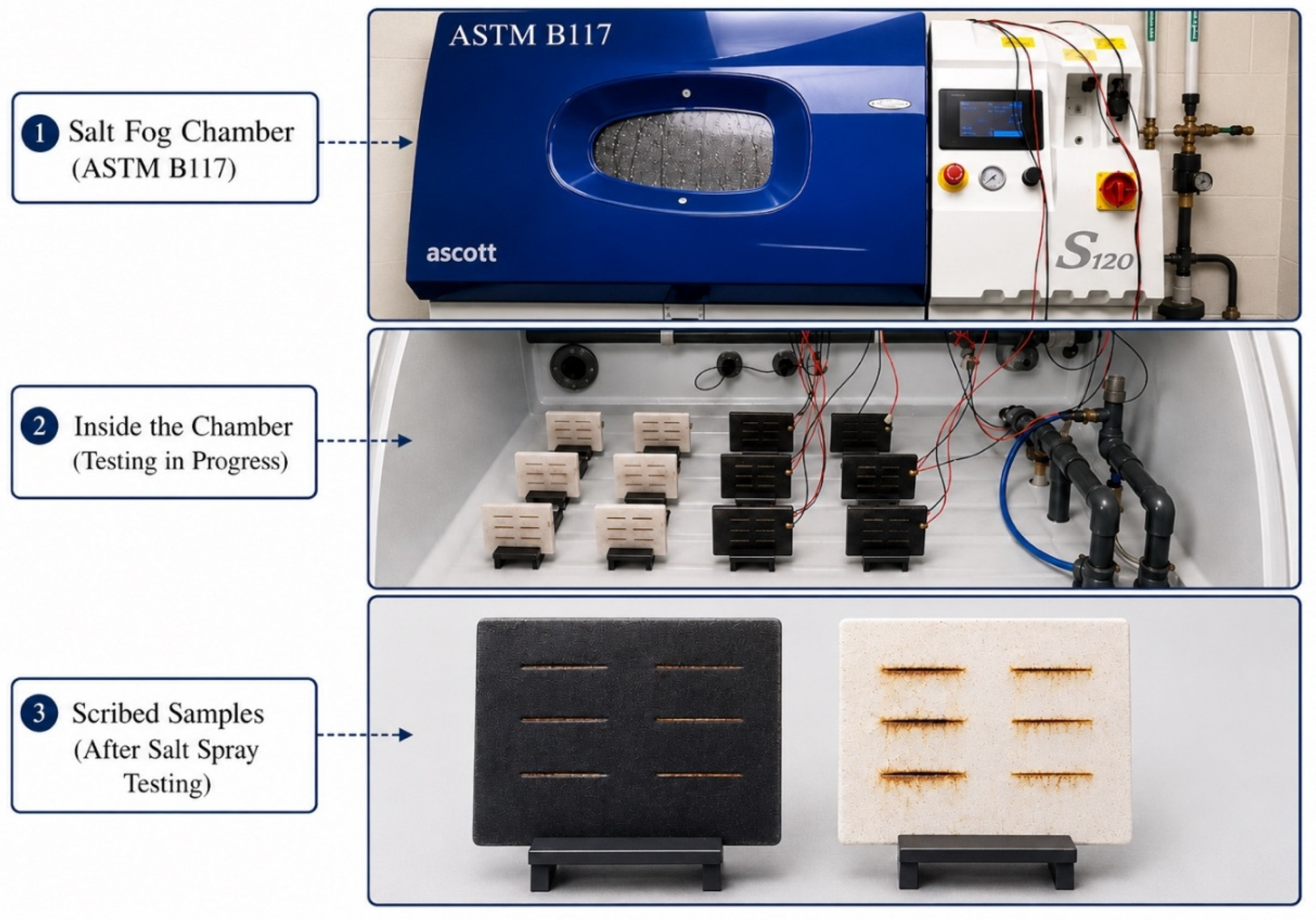
Figure 2.
Optical images of scribed intelligent and Intertherm 228 HS-coated samples exposed to 1.0 wt.% NaCl solution at an SFC temperature of 35 °C and solution pH of 7.0 for 24, 96, and 168 h.
Figure 2.
Optical images of scribed intelligent and Intertherm 228 HS-coated samples exposed to 1.0 wt.% NaCl solution at an SFC temperature of 35 °C and solution pH of 7.0 for 24, 96, and 168 h.

Figure 3.
The SEM images of intelligent coated samples exposed to 1.0 wt.% of NaCl solution, temperature of the SFC is at 35 °C and pH of the solution is at 7.0, (a) 24 hours, (b) 96 hours, and (c) 168 hours.
Figure 3.
The SEM images of intelligent coated samples exposed to 1.0 wt.% of NaCl solution, temperature of the SFC is at 35 °C and pH of the solution is at 7.0, (a) 24 hours, (b) 96 hours, and (c) 168 hours.
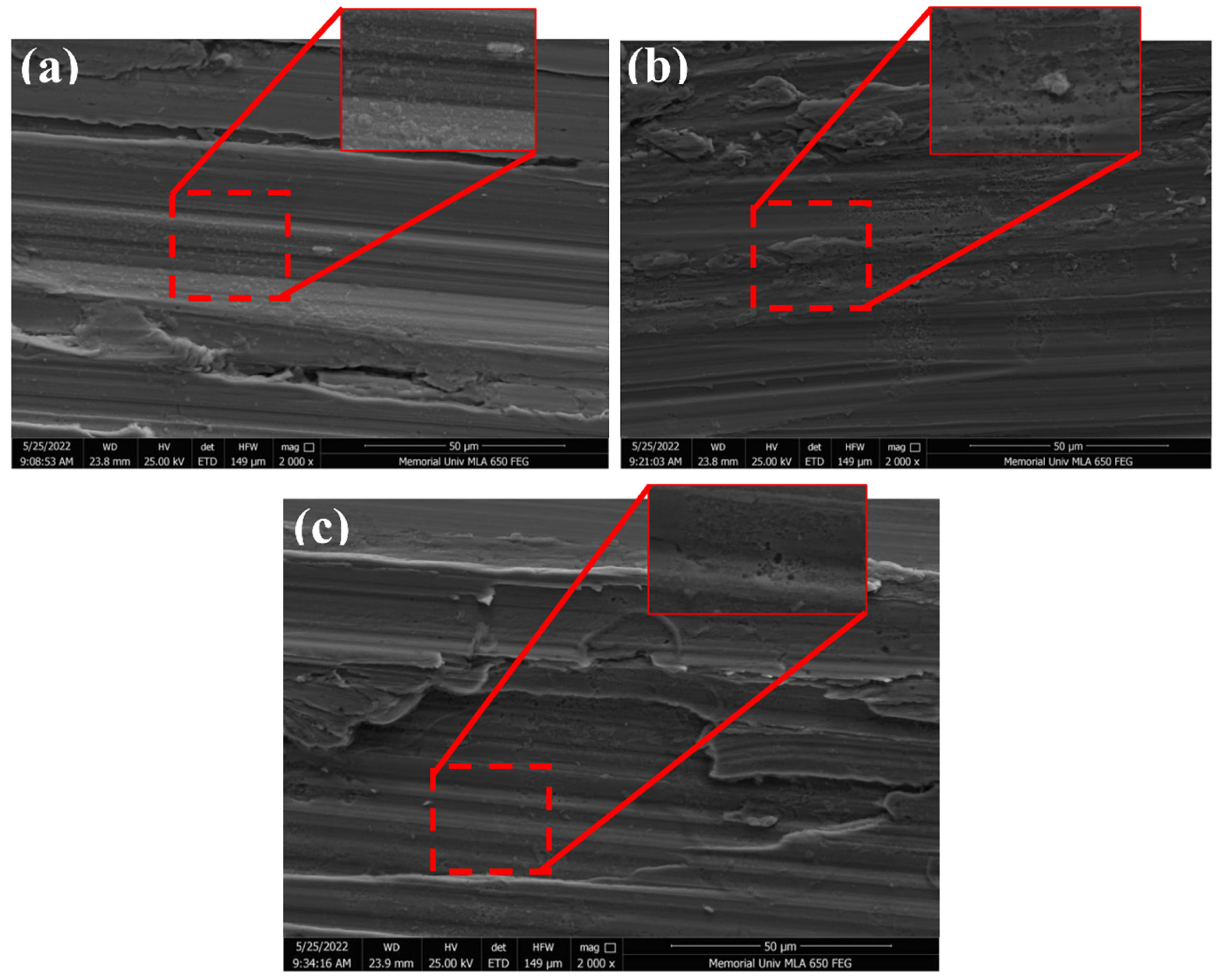
Figure 4.
The SEM images of Intertherm 228 HS coated samples exposed to 1.0 wt.% of NaCl solution, temperature of the SFC is at 35 °C and pH of the solution is at 7.0, (a) 24 hours (without corrosion products) (a1) 24 hours (with corrosion products), (b) 96 hours (without corrosion products) (b1) 96 hours (with corrosion products), and (c) 168 hours (without corrosion products) (c1) 168 hours (with corrosion products).
Figure 4.
The SEM images of Intertherm 228 HS coated samples exposed to 1.0 wt.% of NaCl solution, temperature of the SFC is at 35 °C and pH of the solution is at 7.0, (a) 24 hours (without corrosion products) (a1) 24 hours (with corrosion products), (b) 96 hours (without corrosion products) (b1) 96 hours (with corrosion products), and (c) 168 hours (without corrosion products) (c1) 168 hours (with corrosion products).
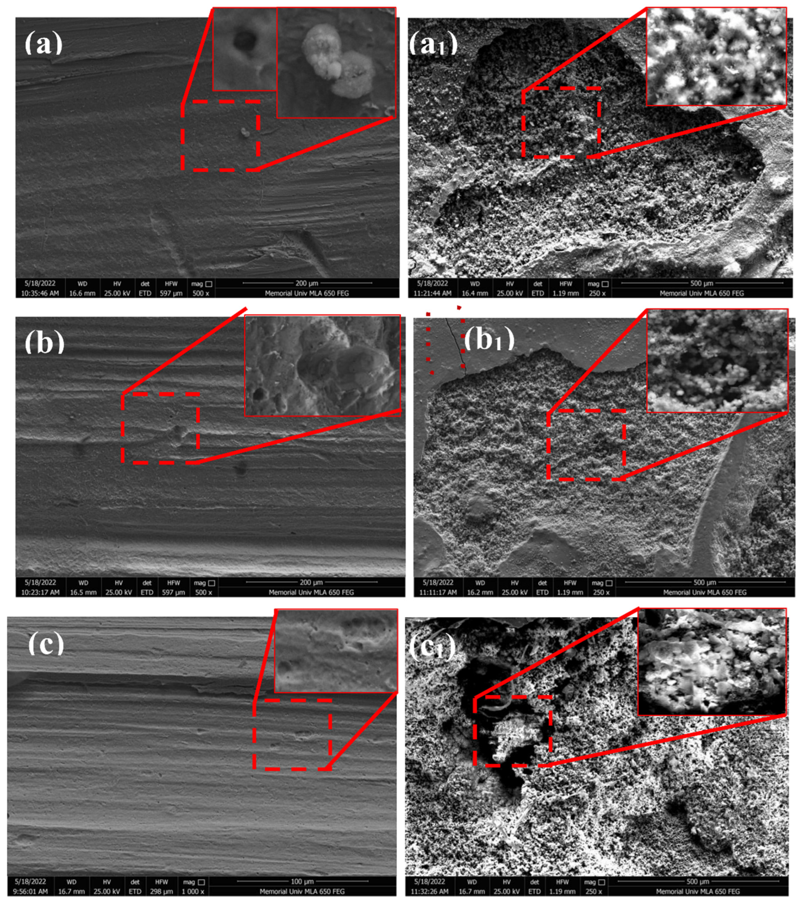
Figure 5.
Optical images of scribed intelligent and Intertherm 228 HS coating exposed at 1.0 wt.% of NaCl solution, temperature of the SFC is at 50 °C and pH of the solution is at 4.0 for 24, 96, and 168 hours.
Figure 5.
Optical images of scribed intelligent and Intertherm 228 HS coating exposed at 1.0 wt.% of NaCl solution, temperature of the SFC is at 50 °C and pH of the solution is at 4.0 for 24, 96, and 168 hours.
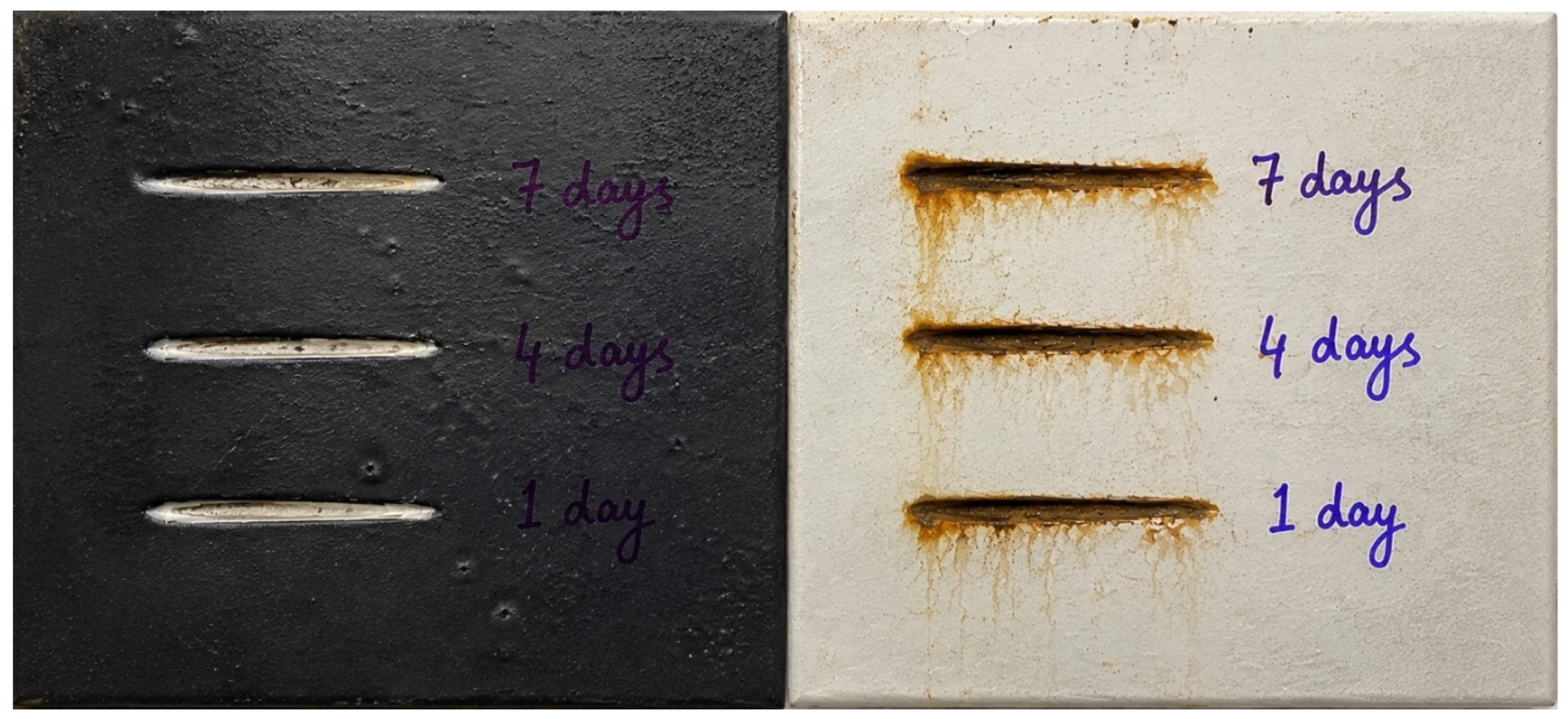
Figure 6.
The SEM images of intelligent coated samples exposed to 1.0 wt.% of NaCl solution, temperature of the SFC is at 50 °C and pH of the solution is at 4.0, (a) 24 hours, (b) 96 hours, and (c) 168 hours.
Figure 6.
The SEM images of intelligent coated samples exposed to 1.0 wt.% of NaCl solution, temperature of the SFC is at 50 °C and pH of the solution is at 4.0, (a) 24 hours, (b) 96 hours, and (c) 168 hours.
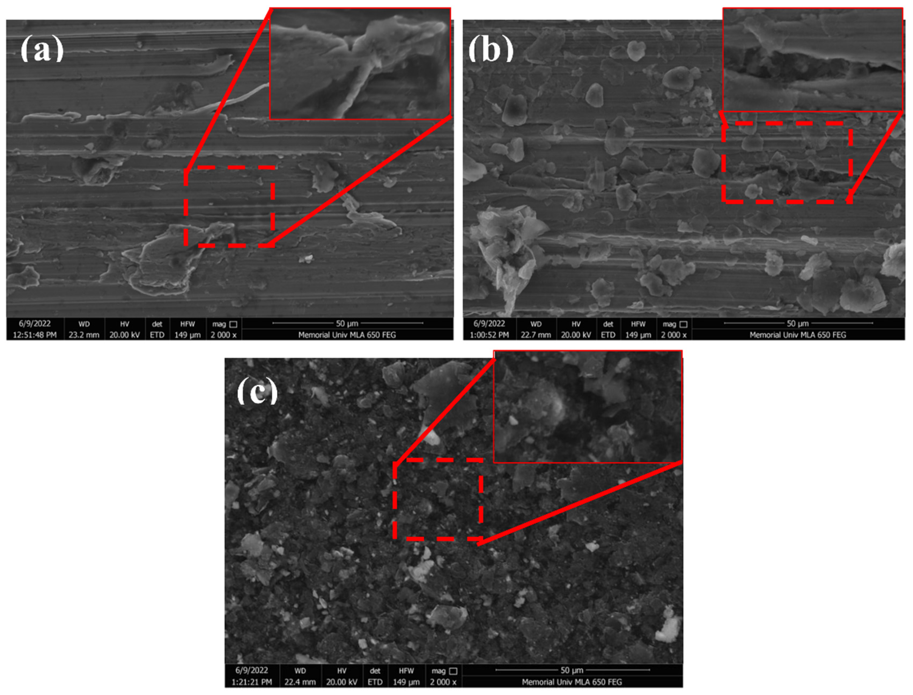
Figure 7.
The SEM images of Intertherm 228 HS coated samples exposed to 1.0 wt.% of NaCl solution, temperature of the SFC is at 50 °C and pH of the solution is at 4.0, (a) 24 hours (without corrosion products) (a1) 24 hours (with corrosion products), (b) 96 hours (without corrosion products) (b1) 96 hours (with corrosion products), and (c) 168 hours (without corrosion products) (a) 168 hours (with corrosion products).
Figure 7.
The SEM images of Intertherm 228 HS coated samples exposed to 1.0 wt.% of NaCl solution, temperature of the SFC is at 50 °C and pH of the solution is at 4.0, (a) 24 hours (without corrosion products) (a1) 24 hours (with corrosion products), (b) 96 hours (without corrosion products) (b1) 96 hours (with corrosion products), and (c) 168 hours (without corrosion products) (a) 168 hours (with corrosion products).
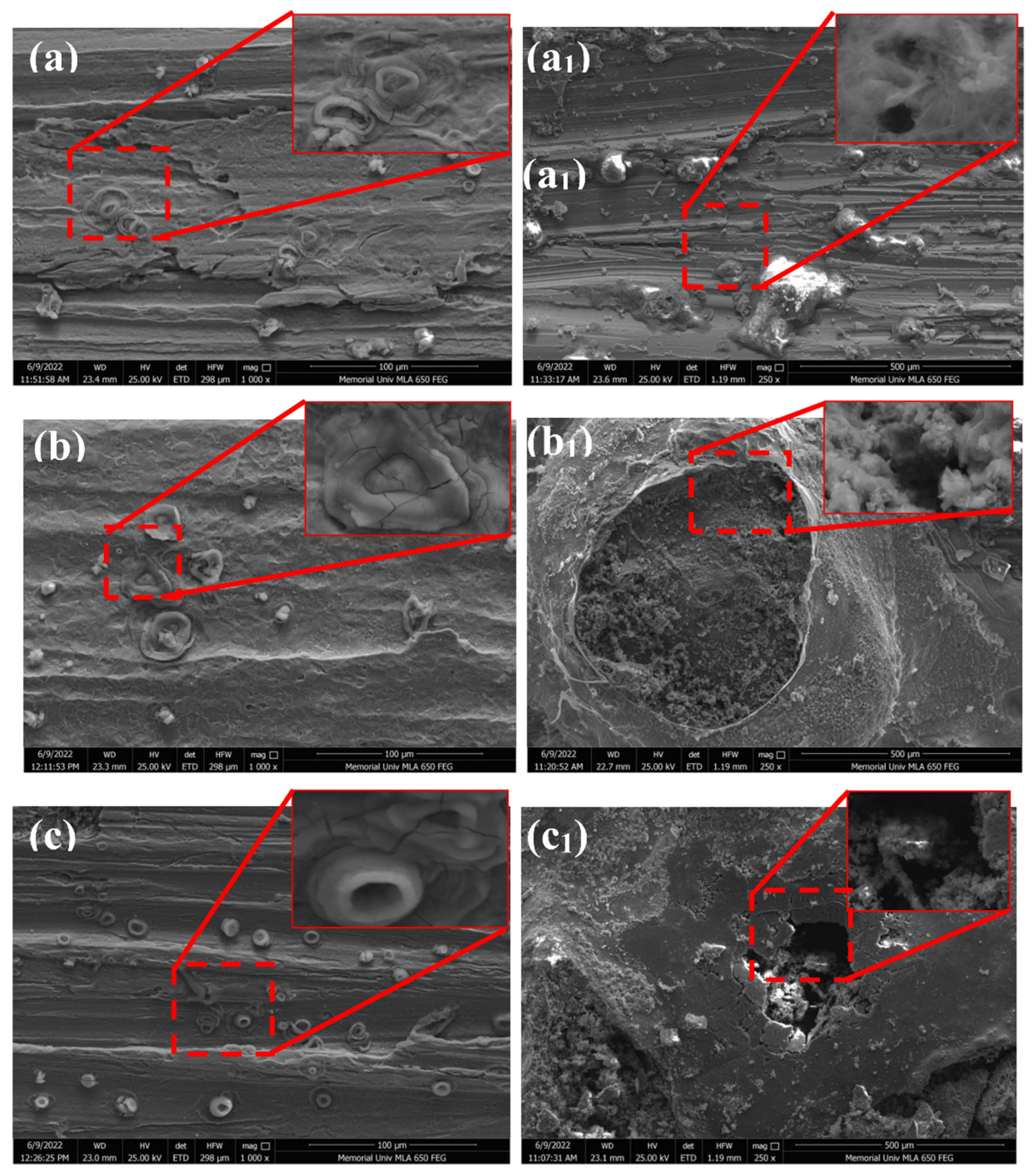
Figure 8.
Optical images of scribed intelligent and Intertherm 228 HS coating exposed at 5.0 wt.% of NaCl solution, temperature of the SFC is at 50 °C and pH of the solution is at 7.0 for 24, 96, and 168 hours.
Figure 8.
Optical images of scribed intelligent and Intertherm 228 HS coating exposed at 5.0 wt.% of NaCl solution, temperature of the SFC is at 50 °C and pH of the solution is at 7.0 for 24, 96, and 168 hours.
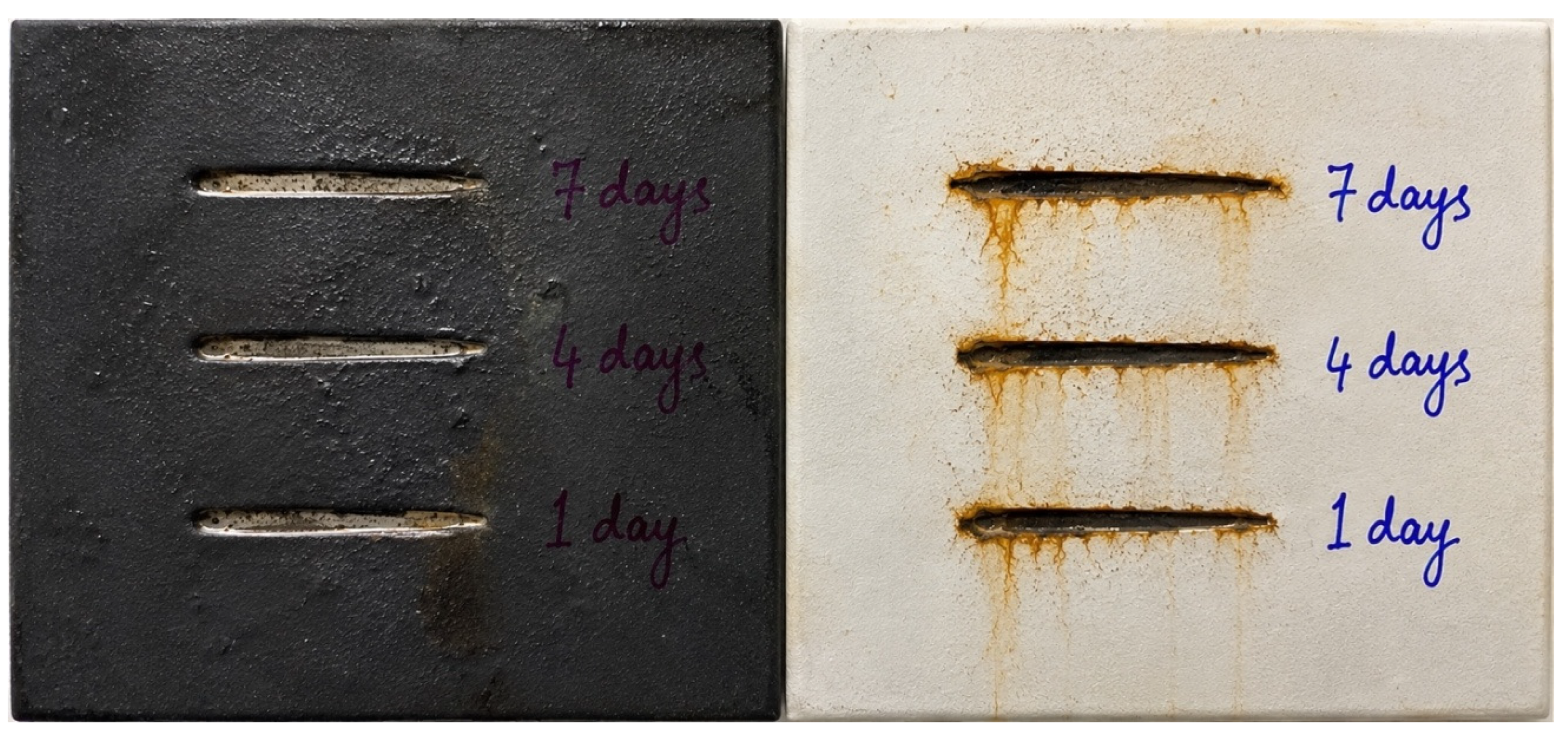
Figure 9.
The SEM images of intelligent coated samples exposed to 5.0 wt.% of NaCl solution, temperature of the SFC is at 50 °C and pH of the solution is at 7.0, (a) 24 hours, (b) 96 hours, and (c) 168 hours.
Figure 9.
The SEM images of intelligent coated samples exposed to 5.0 wt.% of NaCl solution, temperature of the SFC is at 50 °C and pH of the solution is at 7.0, (a) 24 hours, (b) 96 hours, and (c) 168 hours.
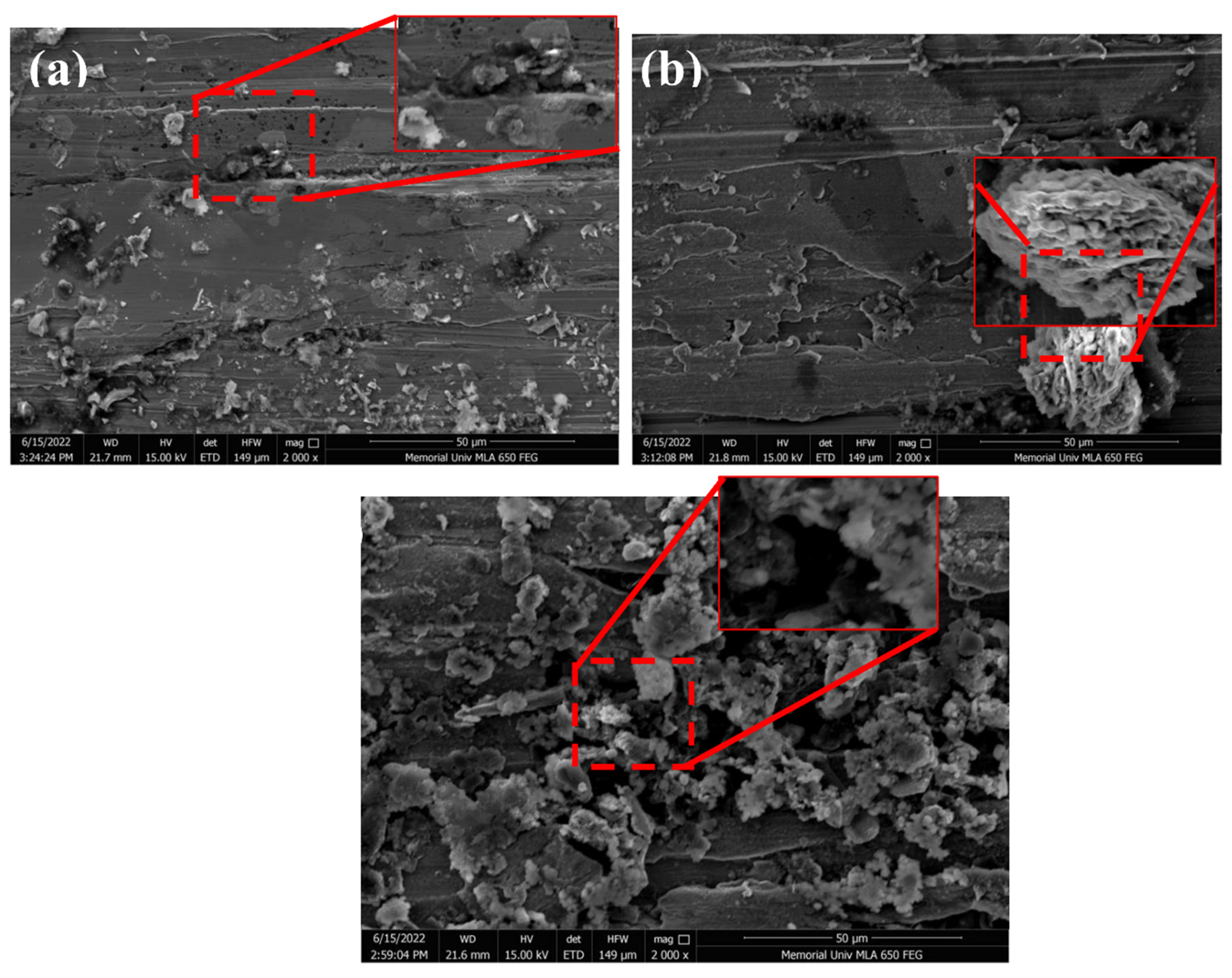
Figure 10.
The SEM images of Intertherm 228 HS coated samples exposed to 5.0 wt.% of NaCl solution, temperature of the SFC is at 50 °C and pH of the solution is at 7.0, (a) 24 hours (without corrosion products) (a1) 24 hours (with corrosion products), (b) 96 hours (without corrosion products) (b1) 96 hours (with corrosion products), and (c) 168 hours (without corrosion products) (a) 168 hours (with corrosion products).
Figure 10.
The SEM images of Intertherm 228 HS coated samples exposed to 5.0 wt.% of NaCl solution, temperature of the SFC is at 50 °C and pH of the solution is at 7.0, (a) 24 hours (without corrosion products) (a1) 24 hours (with corrosion products), (b) 96 hours (without corrosion products) (b1) 96 hours (with corrosion products), and (c) 168 hours (without corrosion products) (a) 168 hours (with corrosion products).
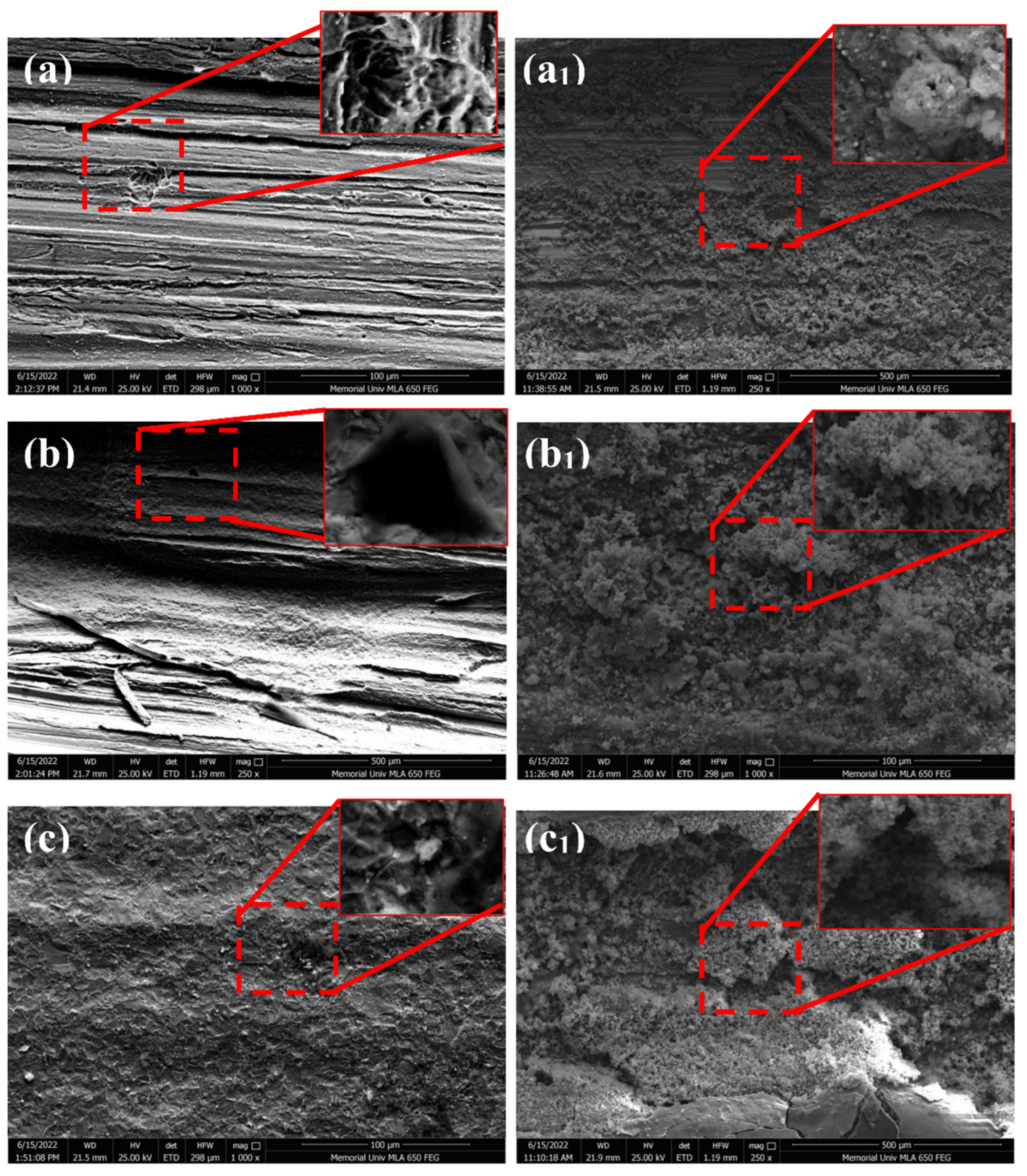
Figure 11.
Optical images of scribed intelligent and Intertherm 228 HS coating exposed at 5.0 wt.% of NaCl solution, temperature of the SFC is at 35 °C and pH of the solution is at 4.0 for 24, 96, and 168 hours.
Figure 11.
Optical images of scribed intelligent and Intertherm 228 HS coating exposed at 5.0 wt.% of NaCl solution, temperature of the SFC is at 35 °C and pH of the solution is at 4.0 for 24, 96, and 168 hours.
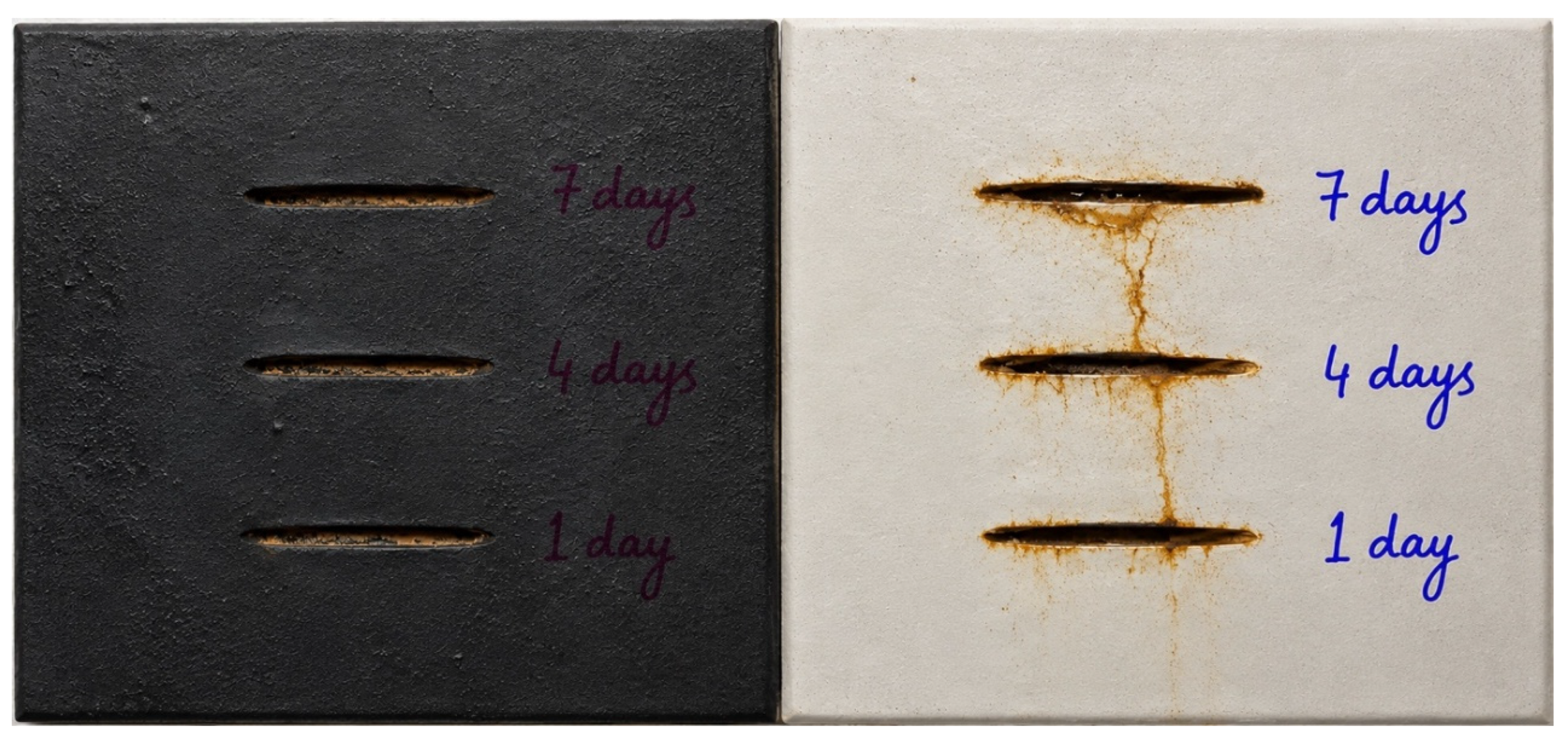
Figure 12.
The SEM images of intelligent coated samples exposed to 5.0 wt.% of NaCl solution, temperature of the SFC is at 35 °C and pH of the solution is at 4.0, (a) 24 hours, (b) 96 hours, and (c) 168 hours.
Figure 12.
The SEM images of intelligent coated samples exposed to 5.0 wt.% of NaCl solution, temperature of the SFC is at 35 °C and pH of the solution is at 4.0, (a) 24 hours, (b) 96 hours, and (c) 168 hours.
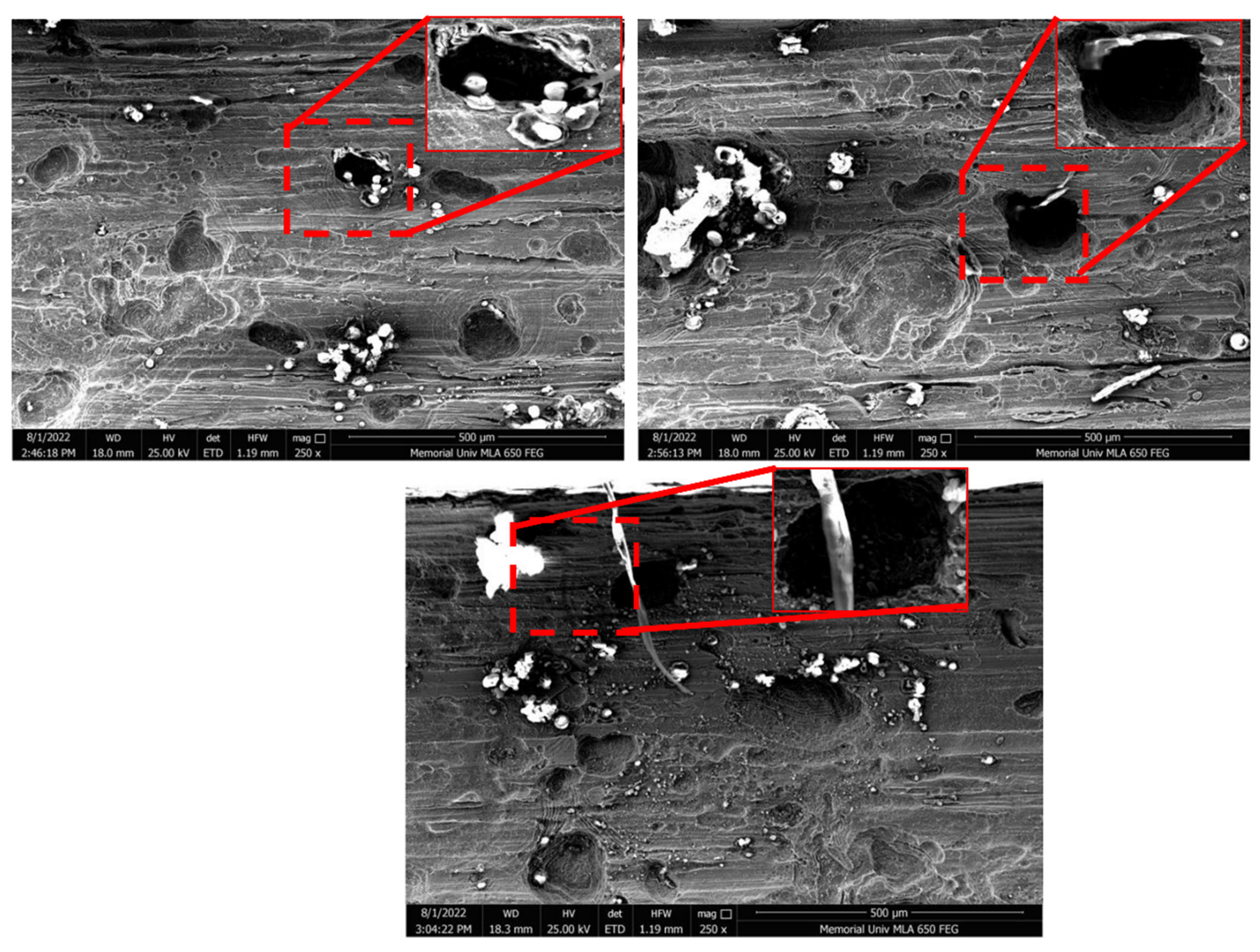
Figure 13.
The SEM images of Intertherm 228 HS coated samples exposed to 5.0 wt.% of NaCl solution, temperature of the SFC is at 35 °C and pH of the solution is at 4.0, (a) 24 hours (without corrosion products) (a1) 24 hours (with corrosion products), (b) 96 hours (without corrosion products) (b1) 96 hours (with corrosion products), and (c) 168 hours (without corrosion products) (a) 168 hours (with corrosion products).
Figure 13.
The SEM images of Intertherm 228 HS coated samples exposed to 5.0 wt.% of NaCl solution, temperature of the SFC is at 35 °C and pH of the solution is at 4.0, (a) 24 hours (without corrosion products) (a1) 24 hours (with corrosion products), (b) 96 hours (without corrosion products) (b1) 96 hours (with corrosion products), and (c) 168 hours (without corrosion products) (a) 168 hours (with corrosion products).
Disclaimer/Publisher’s Note: The statements, opinions and data contained in all publications are solely those of the individual author(s) and contributor(s) and not of MDPI and/or the editor(s). MDPI and/or the editor(s) disclaim responsibility for any injury to people or property resulting from any ideas, methods, instructions or products referred to in the content. |
© 2026 by the author. Licensee MDPI, Basel, Switzerland. This article is an open access article distributed under the terms and conditions of the Creative Commons Attribution (CC BY) license.
Copyright: This open access article is published under a Creative Commons CC BY 4.0 license, which permit the free download, distribution, and reuse, provided that the author and preprint are cited in any reuse.