Submitted:
28 June 2026
Posted:
29 June 2026
You are already at the latest version
Abstract
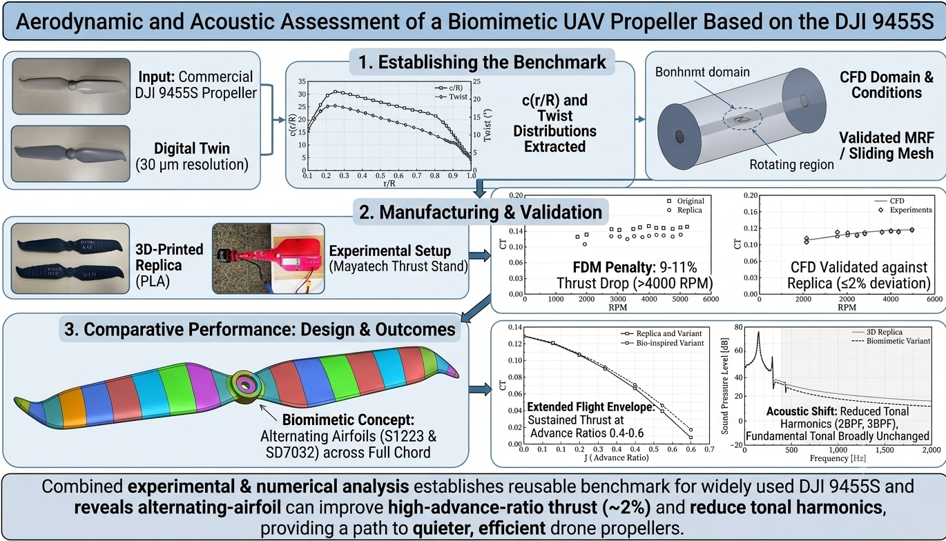
Small unmanned aerial vehicle propellers must generate sufficient thrust while meeting strict noise expectations in civil and industrial drone operations. However, open aerodynamic and geometric data for widely used low-noise propellers remain limited, restricting validation and comparative design studies. This work establishes a public benchmark for the DJI 9455S low-noise propeller and investigates a biomimetic variant inspired by humpback whale tubercles. The commercial propeller was reverse-engineered using high-resolution Faro ScanArm measurements at 30 micrometre resolution to extract its taper and twist distributions. A three-dimensional printed PLA replica and a modified propeller with alternating S1223 high-lift and SD7032 low-drag airfoil sections were manufactured and evaluated using static thrust testing, validated Reynolds-averaged Navier-Stokes simulations, forward-flight calculations and Ffowcs Williams-Hawkings aeroacoustic prediction. The printed replica produced 9-11% less thrust than the commercial propeller above 4000 rpm, highlighting the influence of fused deposition modelling surface roughness, stiffness and geometric deviation. After validation, transient simulations showed that the biomimetic variant increased static thrust by approximately 2%, maintained measurable thrust at advance ratios of 0.4-0.6 and reduced the predicted tonal sound pressure level at the second and third blade-passage harmonics, while leaving the fundamental tone broadly unchanged. These results indicate that full-chord spanwise airfoil alternation can improve UAV propeller tonal acoustic performance while providing reusable benchmark data for future drone propulsion studies.
Keywords:
propellers
; aerodynamics
; reverse engineering
; biomimicry
; whale tubercle effect
; static thrust testing
; 3D printing
; CFD
1. Introduction
The rapid growth of unmanned aerial vehicles (UAVs) in civil, industrial, agricultural, and inspection applications has increased the importance of quiet and efficient propulsion systems [1,2]. For small multi-rotor platforms, the propeller is both the main source of lift and one of the dominant sources of aerodynamic noise. As drones move closer to populated areas, acoustic acceptance has become a design requirement rather than a secondary comfort issue. Future UAV propellers must therefore be assessed not only by thrust and power consumption, but also by their ability to reduce tonal and broadband noise without narrowing the usable flight envelope.
This requirement is particularly challenging for small UAV rotors because they operate at low Reynolds numbers, typically in the range of 10⁴-10⁵. In this regime, thin airfoils, laminar separation bubbles, early stall, surface roughness, and blade deflection can strongly affect the aerodynamic response [3]. These effects also make numerical prediction more sensitive to turbulence modelling assumptions. The k-omega Shear Stress Transport (SST) model remains widely used because it handles adverse pressure gradients and separated flow better than many conventional RANS models [4]. However, validation against reliable experimental data remains essential, especially when a new propeller geometry is introduced. Public datasets such as the UIUC Propeller Database have therefore become important references for checking the credibility of small-rotor simulations [5].
Within the small-UAV propeller category, 9-inch rotors are common in quadcopters and fixed-wing UAV propulsion systems. Examples include the APC Slow Flyer 9 x 4.7, the Master Airscrew E 9 x 6, and the Kyosho 966. DJI Phantom-series propellers, particularly the DJI S9450 and S9455 families, are also frequently used as practical research references. The older DJI 9450 standard propeller has been studied in the open literature [6], whereas the newer DJI 9455S low-noise propeller remains less documented. The S9455S has a raked, curved tip intended to weaken the tip vortex and reduce tonal noise, together with a thin blade profile suited to low-Reynolds-number operation. Despite these useful features, accurate public CAD data and complete performance benchmarks for the 9455S remain limited, with available information mainly appearing in comparisons involving toroidal propellers [7,8]. This lack of open geometry and performance data restricts reproducible CFD validation and makes it difficult to compare new low-noise designs against a well-defined baseline.
Several passive strategies have been proposed to reduce UAV propeller noise. One group of approaches modifies the blade tip through sweep, rake, winglets, or closed-loop toroidal geometries to weaken the tip vortex and reduce tonal sound components [8,9]. A second group modifies the blade edges. Leading-edge and trailing-edge serrations, inspired partly by natural silent-flight mechanisms, break coherent turbulent structures and can reduce broadband noise. Recent work in Drones showed that combining winglets with serration-type flaplets can improve UAV propeller aerodynamic and acoustic performance [10], while outdoor studies have also explored serration-finlet designs for reducing drone-noise annoyance [2]. These strategies confirm that small geometric changes can meaningfully change propeller noise. However, sharp serrations and very thin edge features may be difficult to manufacture robustly at small scale and may reduce structural margin in rapidly rotating blades.
A structurally safer biomimetic alternative is the leading-edge tubercle concept, inspired by the pectoral fins of humpback whales. Tubercles generate streamwise vortices that redistribute momentum along the span, delay flow separation, and improve post-stall behaviour [11]. Their benefits have been reported in hydrofoils and marine propulsors, including improved off-design performance and cavitation control [12,13]. In aerial applications, numerical and experimental studies on low-Reynolds-number wings and propellers have also shown that tubercle-like protuberances can delay stall and improve aerodynamic loading under separated-flow conditions [14,15,16]. Most UAV-scale propeller designs, however, apply tubercles only as a leading-edge waviness, leaving the rest of the chord unchanged. This leaves open the question of whether a spanwise biomimetic variation extended through the full chord can provide simultaneous aerodynamic and acoustic benefits.
Additive manufacturing provides a practical route for investigating such unconventional propeller geometries, but it introduces its own uncertainty. Fused Deposition Modelling (FDM) is attractive because it is low-cost, rapid, and geometrically flexible. Nevertheless, the layer-by-layer process produces stair-step artefacts and elevated surface roughness, which can disturb the boundary layer, accelerate transition, increase drag, and modify acoustic emissions. Popister et al. [17] specifically showed that surface roughness in 3D-printed UAV propellers is directly relevant to noise generation, while Dinulovic et al. [18] demonstrated that 3D-printed polymer structures can exhibit aeroelastic behaviour under flow loading. Therefore, a 3D-printed propeller cannot automatically be treated as an exact aerodynamic equivalent of an injection-moulded commercial propeller. Its performance penalty must first be quantified before the printed model can be used as a trustworthy baseline for design comparisons.
Reliable acoustic prediction is also required when evaluating new low-noise propeller concepts. The Ffowcs Williams-Hawkings (FW-H) acoustic analogy is widely used to convert unsteady surface pressure data from CFD into far-field sound predictions. Recent comparative work on low-Reynolds-number propellers confirmed that FW-H-based approaches, when coupled with suitably resolved unsteady simulations, remain effective for assessing tonal and broadband aeroacoustic components [19]. This makes the combination of validated aerodynamic simulation and FW-H analysis suitable for evaluating the proposed biomimetic propeller. The FW-H analogy coupled with URANS-resolved surface pressures is reliable for predicting tonal noise contributions (the blade-passage frequency and its harmonics), while quantitative broadband noise prediction requires turbulence-resolving simulation (LES, DES, or hybrid RANS/LES) or direct experimental measurement [19]. The present aeroacoustic analysis is therefore restricted to tonal components.
Based on this motivation, the present study first establishes a public aerodynamic and geometric benchmark for the DJI 9455S low-noise propeller, then uses that benchmark to evaluate a new biomimetic design. The commercial propeller is reverse-engineered using high-resolution 3D scanning, and its taper and twist distributions are extracted. A 3D-printed PLA replica is then manufactured and tested against the commercial propeller to quantify the uncertainty introduced by FDM fabrication. Finally, a biomimetic variant is produced using the same baseline taper and twist but with alternating high-lift S1223 and low-drag SD7032 airfoil sections along the span. Unlike conventional leading-edge-only tubercle designs, this configuration propagates the spanwise geometric variation across the full chord, creating a continuous alternating-airfoil structure intended to influence both loading and wake development.
The specific contributions of this paper are as follows:
- DJI 9455S benchmark: A public benchmark is provided for the DJI 9455S low-noise propeller, including static thrust measurements and reverse-engineered taper and twist distributions.
- 3D-printing uncertainty: The aerodynamic penalty associated with replacing the commercial injection-moulded propeller by an FDM PLA replica is quantified, giving a practical uncertainty estimate for researchers using printed propellers as aerodynamic surrogates.
- Full-chord biomimetic design: A new alternating-airfoil configuration is introduced in which S1223 and SD7032 sections vary along the span, extending the tubercle-inspired concept beyond the leading edge and across the full chord.
- Aerodynamic-acoustic evaluation: The baseline and biomimetic propellers are compared using static testing, validated CFD, forward-flight simulations, and FW-H aeroacoustic prediction to assess both thrust retention and broadband noise reduction.
2. Methodology
2.1. Geometric Reverse-Engineering
To capture the complex geometry of the commercial DJI 9455S propeller (Figure 1), a pristine sample was digitized with a Faro ScanArm at 30-micron resolution. The resulting high-density point cloud was processed and converted into a watertight STEP file (Figure 2). This digital twin was computationally sliced at multiple radial stations to extract the blade's fundamental design parameters. The resulting taper (chord-length distribution, ), and twist distribution are presented in Figure 3, forming the basis of the publicly released geometric data provided by this study. The original airfoil cross-sections are withheld out of respect for the manufacturer's intellectual property; the released distributions are combined with open-literature airfoils (S1223 and SD7032) for the biomimetic design study below.
Two primary propeller configurations were manufactured for comparative analysis:
- Baseline Replica: A direct 1:1 copy of the 3D-scanned DJI 9455S geometry. This model serves to validate the digital extraction process and quantify the aerodynamic penalties incurred by 3D printing.
- Biomimetic "Tubercle-Effect" Variant: This propeller was engineered utilizing the same baseline taper and twist distributions as the 9455S, but the airfoil cross-section was fundamentally modified. It features alternating segments of the high-lift S1223 airfoil and the low-drag SD7032 airfoil along the span, as illustrated conceptually in Figure 4. This creates a serrated leading edge mimicking the tubercle effect.
Both the baseline replica and the biomimetic variant were fabricated using an Elegoo Neptune 4 FDM 3D printer. A layer height of 0.1 mm and a print speed of 20 mm/s were selected to produce high-fidelity physical models (Figure 5) utilizing Polylactic Acid (PLA), ensuring structural integrity suitable for aerodynamic testing.
2.2. Experimental Setup: Static Thrust Testing
Experimental static thrust measurements were conducted to characterize hover performance. Three propellers were tested: (i) the original commercial DJI 9455S, (ii) the 3D-printed baseline replica, and (iii) the 3D-printed biomimetic variant. Each propeller was securely mounted on a Mayatech 5 thrust stand and driven by a BAT B3115 900KV brushless DC (BLDC) motor (Figure 6 and Figure 7). Thrust data was recorded across a rotational speed range of 2000 to 5000 RPM. Static thrust measurements were performed using a Mayatech 5 commercial thrust stand, which integrates a strain-gauge load cell, an optical RPM sensor, and a digital readout. Before the test campaign, a single-point verification of the load cell was carried out by hanging a known 2.5 kg reference mass from the stand; the displayed reading matched the applied mass to within ±1 g, confirming correct full-scale response. A load-cell accuracy of ±1 g is therefore adopted as the absolute thrust uncertainty for the present study. All three propellers (the commercial DJI 9455S, the 3D-printed baseline replica, and the biomimetic variant) were tested back-to-back in the same session using the same motor, ESC, and power supply. This protocol means that, while absolute thrust is bounded by the load-cell accuracy, the relative comparison between the three propellers — which is the central claim of this paper — is unaffected by inter-session drift and forms the basis on which the conclusions are drawn.
2.3. Computational Fluid Dynamics (CFD) Setup
Numerical simulations were performed using ANSYS Fluent to analyze the fluid dynamics of the rotors. In our CFD framework, a Moving Reference Frame (MRF) approach was adopted to simulate rotor rotation [20]. The MRF approach was utilized primarily because it is highly computationally efficient and fast when accelerated using a GPU. The exception to this was for specific data points where we chose to conduct an acoustic study; for those cases, we employed an unsteady simulation (Sliding Mesh) with a time step of seconds. We acknowledge that there is a slight difference between the force outputs derived from the MRF and the sliding mesh approaches. However, we retained the MRF method for the broader performance mapping for the sake of significant time savings.
The computational domain consisted of a rotating sub-domain enclosing the propeller and a stationary far-field extending 30 rotor diameters (30D) downstream (Figure 8). A high-fidelity unstructured polyhedral mesh consisting of 13 million elements was generated, featuring 15 inflation layers to ensure a non-dimensional wall distance of , strictly required for resolving the viscous sublayer.
Boundary conditions were assigned as follows. The upstream face of the cylindrical far-field was set as a velocity inlet, with axial inflow speed equal to zero for the static (hover) cases and equal to the target freestream velocity V∞ for the forward-flight sweep; inlet turbulence quantities were left at the Fluent default values (turbulence intensity 5% and turbulent viscosity ratio 10), which is appropriate for a quiescent external flow at this Reynolds number. The downstream face was set as a pressure outlet at zero gauge pressure. The cylindrical side walls of the far-field were modelled as slip walls (zero shear, free tangential velocity) to allow the domain boundary to remain non-intrusive while preventing artificial radial inflow. The propeller surface was modelled as a no-slip wall, rotating with the rotor in the MRF formulation and translating as a moving wall in the sliding-mesh transient runs. Working-fluid properties corresponded to standard air at 25 °C: density ρ = 1.225 kg/m³ and dynamic viscosity μ = 1.7894 × 10⁻⁵ Pa·s. Pressure–velocity coupling used the SIMPLEC scheme with second-order upwind spatial discretisation for the momentum and turbulence transport equations, and second-order implicit time advancement was used for the sliding-mesh runs. Convergence was declared when scaled residuals for continuity, momentum, and the k and ω equations fell below 1 × 10⁻⁴ and the monitored thrust value stabilised to within ±0.5% over the final 200 iterations (for steady MRF) or three full rotor revolutions (for sliding mesh).
The Shear Stress Transport (SST) Reynolds-Averaged Navier-Stokes (RANS) turbulence model was selected due to its superior performance in capturing flow separation and adverse pressure gradients at low Reynolds numbers () [21]. While RANS models can exhibit minor errors at low Reynolds numbers, the numerical results remain closely aligned with the static performance of the 3D replica. For instance, the error at 4000 RPM between the CFD predictions and the 3D replica's experimental data is approximately 2%; this validation is presented in detail in Section 3.2. To verify the numerical framework, the setup was first validated against published experimental data for a baseline APC propeller [5,22] yielding a deviation of less than 7% at the design point.
3. Results and Discussions
3.1. Baseline Characterization: Original vs. 3D-Printed Replica
To establish a benchmark and quantify the fidelity of the 3D-printed replica. Static thrust tests were performed on both the original commercial DJI 9455S propeller and the 3D-printed PLA replica. The experimental results revealed a consistent, albeit small, performance drop in the 3D-printed version compared to the original commercial injection-molded model. This deviation, typically observed as a 9-11% reduction in thrust at RPMs higher than 4000, is attributed to multiple sources of uncertainty. Primary factors include geometric error arising from the 3D scanning process and subsequent geometric deviation introduced during FDM 3D printing. Furthermore, differences in material stiffness (PLA vs. glass-filled polypropylene) leading to varying aeroelastic deflection under load, as well as the increased surface roughness inherent to the FDM printing process, contribute to this drop. This finding is critical, as it provides a quantifiable uncertainty margin for researchers utilizing 3D-printed propellers as surrogates for commercial counterparts.
Figure 9.
Measured static thrust coefficient (CT) versus rotational speed for the commercial DJI 9455S and its FDM-printed PLA replica, obtained on the Mayatech thrust stand.
Figure 9.
Measured static thrust coefficient (CT) versus rotational speed for the commercial DJI 9455S and its FDM-printed PLA replica, obtained on the Mayatech thrust stand.

3.2. Validation of the CFD Model Against the 3D-Printed Replica
To ensure the accuracy of the numerical simulations, the CFD model of the baseline replica was validated against its corresponding experimental thrust data. Figure 10 presents the static Thrust Coefficient () versus RPM. The close agreement between the CFD predictions (squares) and the experimental measurements derived from the thrust tester (diamonds) confirms that the numerical setup accurately captures the aerodynamics of the manufactured propeller. The deviation is less than 2% at RPMs higher than 4000. This robust validation provides high confidence in the subsequent CFD comparisons between the replica and the biomimetic variant.
3.3. Comparative Performance: Replica vs. Biomimetic Variant
The core of this investigation lies in the direct comparison between the baseline 3D-printed replica and the novel tubercle-effect propeller.
3.3.1. Static (Hover) Performance
In static thrust tests, the performance of the biomimetic propeller was initially evaluated across a range of rotational speeds using the Moving Reference Frame approach. As shown in Figure 11, the static thrust coefficient for both the biomimetic and baseline propellers was almost identical under these conditions. The Moving Reference Frame method provides a steady state approximation and is highly effective for calculating the average aerodynamic parameters of a rotating body [20].
However, to capture the transient pressure fluctuations required for the subsequent acoustic analysis, a high-fidelity Sliding Mesh simulation was performed at a specific operating point of 4000 revolutions per minute. This transient simulation utilized a highly refined time step of seconds, which divides a single rotation into 1080 precise divisions. Interestingly, while resolving the unsteady aerodynamics for the acoustic evaluation, the data revealed that the biomimetic propeller's thrust coefficient exceeded that of the baseline replica by 2 percent.
This finding is scientifically significant. It indicates that while the time-averaged thrust remains comparable across the broader RPM range, the alternating airfoil design provides a slight aerodynamic advantage when dynamic vortex interactions are fully resolved. The detailed noise reduction benefits derived from this specific transient simulation are discussed in the following acoustic analysis section.
Figure 12.
Predicted power coefficient (CP) versus RPM for the 3D-printed replica and the biomimetic variant, computed with steady MRF k-ω SST simulations under hover conditions.
Figure 12.
Predicted power coefficient (CP) versus RPM for the 3D-printed replica and the biomimetic variant, computed with steady MRF k-ω SST simulations under hover conditions.

3.3.2. Forward Flight Performance (CFD)
The forward flight performance was evaluated using computational fluid dynamics by plotting the thrust coefficient against the advance ratio. As shown in Figure 13, the simulations revealed that both propellers perform similarly at lower forward speeds. Specifically, between an advance ratio of 0.0 and 0.3, the thrust coefficient of the biomimetic propeller is virtually identical to the baseline replica. This indicates that the biomimetic modifications do not adversely affect the standard aerodynamic efficiency under typical cruising conditions.
However, a distinct performance advantage emerges as the advance ratio increases. Starting from an advance ratio of 0.4 and continuing up to 0.6, the biomimetic propeller demonstrates a consistently higher thrust coefficient compared to the baseline model. The most significant difference is observed at an advance ratio of 0.6. At this extreme point, the thrust of the baseline replica drops almost entirely to zero, whereas the biomimetic variant continues to generate measurable thrust.
This sustained thrust at high advance ratios represents a major aerodynamic benefit. As an aircraft's forward flight speed increases, the incoming air velocity changes the effective angle of attack on the blades, typically leading to a rapid loss of thrust. The data clearly show that the alternating airfoil design effectively manages high-velocity airflow to prevent such a sudden drop. By maintaining thrust production at higher advance ratios, the biomimetic propeller successfully widens the operational flight envelope. Consequently, this makes the design particularly advantageous for high-speed forward flight or for operating against strong headwinds.
3.3.3. Aeroacoustic Analysis
Figure 14 presents the predicted acoustic frequency spectrum comparing the baseline 3D-printed replica and the biomimetic variant at 4000 RPM. Both designs reproduce the fundamental blade-passage frequency (BPF) at approximately 133 Hz with comparable tonal magnitude, indicating that the alternating-airfoil modification does not amplify the dominant tonal source. The second and third harmonics of the BPF, near 267 Hz and 400 Hz respectively, are visibly lower for the biomimetic variant. This shift in the higher-harmonic tonal content is consistent with the spanwise loading redistribution produced by the alternating S1223 / SD7032 sections, which reduces the periodic pressure fluctuation amplitude seen by the far-field observer at each blade passage.
It must be emphasised that the URANS+FW-H framework employed here is reliable for tonal acoustic prediction but cannot quantitatively resolve the broadband noise component, which originates from small-scale turbulent fluctuations not represented by RANS-based closures. The spectral trends above approximately 400 Hz should therefore be interpreted qualitatively. Quantitative assessment of broadband acoustic emissions for this propeller will require turbulence-resolving simulation (e.g., LES or hybrid RANS/LES) or direct anechoic-chamber measurement, and is identified as a logical continuation of the present work.
4. Conclusions
This study developed a publicly released benchmark for the DJI 9455S propeller and introduced a biomimetic variant inspired by whale tubercles. The commercial propeller was reverse engineered using high resolution 3D scanning, and its taper and twist distributions were extracted together with a complete static thrust dataset. Although the original airfoil sections were not released to respect the manufacturer’s intellectual property, the released geometry distributions were combined with open literature airfoils to produce a useful and high performing research propeller. The comparison between the commercial propeller and the FDM printed PLA replica showed a thrust reduction of 9 to 11% above 4000 RPM, which confirms that surface roughness, lower stiffness, and small manufacturing deviations can noticeably affect small UAV propeller performance.
The biomimetic propeller improved the printed baseline by increasing static thrust by about 2%. It also maintained measurable thrust at advance ratios up to 0.6, where the baseline produced almost no thrust. In addition, it reduced the predicted tonal sound pressure level at the second and third blade-passage harmonics while leaving the fundamental tone broadly unchanged. These results show that the alternating airfoil concept can improve thrust and reduce noise at the same time. Overall, this work provides a reusable dataset for UAV researchers and presents a practical route toward quieter and more efficient drone propellers. Quantitative assessment of the broadband acoustic contribution will require turbulence-resolving simulation or anechoic-chamber measurement and is a natural extension of the present study. Future work should test the design in multi rotor systems and under realistic flight conditions.
Funding
This work was supported by King Fahd University of Petroleum and Minerals (KFUPM) through internal research grant INAE2405.
Clinical Trial Registration
Not applicable.
Consent to Publish Declaration
Not applicable.
Ethics and Consent to Participate declarations
Not applicable.
Data Availability
The datasets generated during and/or analysed during the current study are available from the corresponding author on reasonable request.
Nomenclature
Roman symbols
| Symbol | Meaning | Unit |
| c | chord length | m |
| CP | power coefficient | — |
| CT | thrust coefficient | — |
| D | propeller diameter | m |
| J | advance ratio, V∞ / (nD) | — |
| n | rotational speed | rev/s |
| R | propeller radius | m |
| r | radial position | m |
| Re | Reynolds number | — |
| T | thrust | N |
| V∞ | freestream velocity | m/s |
| y⁺ | non-dimensional wall distance | — |
Greek symbols
| Symbol | Meaning | Unit |
| μ | dynamic viscosity | Pa·s |
| ρ | air density | kg/m³ |
| ω | angular velocity | rad/s |
Acronyms
| Acronym | Meaning |
| BLDC | Brushless DC (motor) |
| BPF | Blade-Passage Frequency |
| CFD | Computational Fluid Dynamics |
| ESC | Electronic Speed Controller |
| FDM | Fused Deposition Modelling |
| FW-H | Ffowcs Williams–Hawkings |
| LES | Large Eddy Simulation |
| MRF | Moving Reference Frame |
| PLA | Polylactic Acid |
| RANS | Reynolds-Averaged Navier–Stokes |
| RPM | Revolutions Per Minute |
| SPL | Sound Pressure Level |
| SST | Shear Stress Transport |
| UAV | Unmanned Aerial Vehicle |
| URANS | Unsteady RANS |
References
- Josephat, A.; Sekar, A.; T, D.; Angalaeswari, S. Design and development of agricultural drone for precision fertilizer application to optimize crop yields. Results Eng. 2025, 27, 106267. [Google Scholar] [CrossRef]
- Shen, Y.; Bai, Y.; Liu, X.; Zang, B. Drone Noise Reduction Using Serration-Finlet Blade Design and Its Psychoacoustic and Social Impacts. Sustainability 2025, 17, 3451. [Google Scholar] [CrossRef]
- Perez Gordillo, A.M.; Escobar, J.A.; Lopez Mejia, O.D. Influence of the Reynolds Number on the Aerodynamic Performance of a Small Rotor. Aerospace 2023, 10, 130. [Google Scholar] [CrossRef]
- Sourirajan, L.; Baskaran, B.; Rajapandi, R.; Sakthivel, P.; Stanislaus Arputharaj, B.; Karuppasamy, A.; Singh, S.; et al. Design, aerodynamic, and structural integrity investigations of the advanced three bladed propeller for high payload based unmanned aerial vehicles. Results Eng. 2025, 26, 104573. [Google Scholar] [CrossRef]
- Brandt, J.B.; Deters, R.W.; Ananda, G.K.; Dantsker, O.D.; Selig, M.S. UIUC Propeller Database; University of Illinois at Urbana-Champaign: Urbana, IL, USA, 2024. [Google Scholar]
- Ali, M.I.M.; Afandi, A.N.; Bardai, A.M. Analysis on Propeller Design for Medium-Sized Drone (DJI Phantom 3). Int. J. Innov. Technol. Explor. Eng. 2019. [Google Scholar]
- Thomas, S.; Christopher, S. Toroidal Propeller. U.S. Patent No. 20190135410A1, 9 May 2019. [Google Scholar]
- Wei, W.; Ma, Y.; Wei, S.; Wang, D.; Guo, M.; Yan, Q. Analysis and Evaluation of Aerodynamic Noise Characteristics of Toroidal Propeller. Drones 2024, 8, 753. [Google Scholar] [CrossRef]
- Yao, H.-D.; Huang, Z.; Davidson, L.; Niu, J.; Chen, Z.-W. Blade-Tip Vortex Noise Mitigation Traded-Off against Aerodynamic Design for Propellers of Future Electric Aircraft. Aerospace 2022, 9, 825. [Google Scholar] [CrossRef]
- Khalaf, A.; Kennedy, J. The Dual Impact of Winglets and Serrations on UAV Aerodynamic and Acoustic Performance. Drones 2025, 9, 302. [Google Scholar] [CrossRef]
- Miklosovic, D.S.; Murray, M.M.; Howle, L.E.; Fish, F.E. Leading-edge tubercles delay stall on humpback whale (Megaptera novaeangliae) flippers. Phys. Fluids 2004, 16, L39–L42. [Google Scholar] [CrossRef]
- Stark, C.; Shi, W. Hydroacoustic and hydrodynamic investigation of bio-inspired leading-edge tubercles on marine-ducted thrusters. R. Soc. Open Sci. 2021, 8, 210402. [Google Scholar] [CrossRef] [PubMed]
- Usta, O.; Oksuz, S.; Celik, F. Effect of leading-edge tubercles and surface corrugations on the performance and cavitation characteristics of twisted hydrofoils. Ocean Eng. 2025, 335, 121663. [Google Scholar] [CrossRef]
- Rafi Butt, F.; Talha, T. Numerical Investigation of the Effect of Leading-Edge Tubercles on Propeller Performance. J. Aircr. 2019, 56, 1014–1028. [Google Scholar] [CrossRef]
- Gopinathan, V.T.; Bruce Ralphin Rose, J. Aerodynamic performance characterization of bio-inspired wings with leading edge tubercles at low Reynolds number. Proc. Inst. Mech. Eng. Part G. J. Aerosp. Eng. 2023, 237, 86–103. [Google Scholar] [CrossRef]
- Nikhade, R.T.; Joshi, G.N. Computational study on aerodynamic characteristics of propeller with protuberances. Aerosp. Syst. 2025, 8, 359–367. [Google Scholar] [CrossRef]
- Popister, F.; Goia, H.S.; Ciudin, P. Influence of Polymers Surface Roughness on Noise Emissions in 3D-Printed UAV Propellers. Polymers 2025, 17, 1015. [Google Scholar] [CrossRef] [PubMed]
- Dinulovic, M.; Peric, M.; Stamenkovic, D.; Bengin, A.; Adzic, V.; Trninic, M. Aeroelastic Behavior of 3D-Printed Tapered Polylactic Acid Plates Under Subsonic Flow Conditions. Materials 2025, 18, 1127. [Google Scholar] [CrossRef] [PubMed]
- Huang, G.; Sharma, A.; Chen, X.; Riaz, A.; Jefferson-Loveday, R. Numerical Predictions of Low-Reynolds-Number Propeller Aeroacoustics: Comparison of Methods at Different Fidelity Levels. Aerospace 2025, 12, 154. [Google Scholar] [CrossRef]
- Takeyeldein, M.M.; Ishak, I.S.; Lazim, T.M. Wind-lens turbine design for low wind speed. Wind Struct. 2022, 35, 147–155. [Google Scholar] [CrossRef]
- Takeyeldein, M.M.; Ishak, I.S.; Lazim, T.M. The effect of the number of the blades on diffuser augmented wind turbine performance. J. Eng. Sci. Technol. 2023, 18. [Google Scholar]
- McCrink, M.; Gregory, J.W. Blade Element Momentum Modeling of Low-Re Small UAS Electric Propulsion Systems. In Proceedings of the 33rd AIAA Applied Aerodynamics Conference, Dallas, TX, USA, 22–26 June 2015. [Google Scholar] [CrossRef]
Figure 1.
Photograph of the commercial DJI 9455S low-noise propeller used as the geometric reference and aerodynamic baseline of this study.
Figure 1.
Photograph of the commercial DJI 9455S low-noise propeller used as the geometric reference and aerodynamic baseline of this study.

Figure 2.
Reverse-engineered solid model of the DJI 9455S, reconstructed from Faro ScanArm point-cloud data and exported as a watertight STEP geometry.
Figure 2.
Reverse-engineered solid model of the DJI 9455S, reconstructed from Faro ScanArm point-cloud data and exported as a watertight STEP geometry.

Figure 3.
Spanwise distributions of normalised chord (c/R) and geometric twist extracted from the scanned DJI 9455S blade; r/R denotes the non-dimensional radial coordinate.2.2 Propeller Design and Manufacturing.
Figure 3.
Spanwise distributions of normalised chord (c/R) and geometric twist extracted from the scanned DJI 9455S blade; r/R denotes the non-dimensional radial coordinate.2.2 Propeller Design and Manufacturing.

Figure 4.
CAD model of the biomimetic variant, built from the reference DJI 9455S taper and twist with alternating spanwise sections of the high-lift S1223 and low-drag SD7032 airfoils.
Figure 4.
CAD model of the biomimetic variant, built from the reference DJI 9455S taper and twist with alternating spanwise sections of the high-lift S1223 and low-drag SD7032 airfoils.

Figure 5.
FDM-printed PLA propellers used in the experimental campaign: the baseline replica of the DJI 9455S and the biomimetic alternating-airfoil variant.
Figure 5.
FDM-printed PLA propellers used in the experimental campaign: the baseline replica of the DJI 9455S and the biomimetic alternating-airfoil variant.

Figure 6.
Experimental rig: Mayatech 5 thrust stand instrumented with the BAT B3115 900KV brushless DC motor used to drive all three test propellers.
Figure 6.
Experimental rig: Mayatech 5 thrust stand instrumented with the BAT B3115 900KV brushless DC motor used to drive all three test propellers.

Figure 7.
Propellers mounted on the test stand: (a) commercial DJI 9455S, and (b) FDM-printed biomimetic variant.
Figure 7.
Propellers mounted on the test stand: (a) commercial DJI 9455S, and (b) FDM-printed biomimetic variant.

Figure 8.
Computational domain and applied boundary conditions: a rotating sub-domain enclosing the propeller, nested within a cylindrical far-field extending 30 rotor diameters downstream.
Figure 8.
Computational domain and applied boundary conditions: a rotating sub-domain enclosing the propeller, nested within a cylindrical far-field extending 30 rotor diameters downstream.

Figure 10.
CFD validation against experiment for the FDM-printed replica: static thrust coefficient (CT) versus RPM, comparing k-ω SST RANS predictions with thrust-stand measurements.
Figure 10.
CFD validation against experiment for the FDM-printed replica: static thrust coefficient (CT) versus RPM, comparing k-ω SST RANS predictions with thrust-stand measurements.

Figure 11.
Predicted static thrust coefficient (CT) versus RPM for the 3D-printed replica and the biomimetic variant, computed with steady MRF k-ω SST simulations under hover conditions.
Figure 11.
Predicted static thrust coefficient (CT) versus RPM for the 3D-printed replica and the biomimetic variant, computed with steady MRF k-ω SST simulations under hover conditions.

Figure 13.
Predicted thrust coefficient (CT) versus advance ratio (J) for the 3D-printed replica and the biomimetic variant, obtained from the validated k-ω SST CFD model in forward flight.
Figure 13.
Predicted thrust coefficient (CT) versus advance ratio (J) for the 3D-printed replica and the biomimetic variant, obtained from the validated k-ω SST CFD model in forward flight.

Figure 14.
Predicted Sound Pressure Level (SPL) spectra at 4000 RPM under static conditions for the 3D-printed replica and the biomimetic variant, computed with the Ffowcs Williams–Hawkings acoustic analogy on URANS-resolved surface pressures; tonal peaks at the blade-passage frequency (BPF ≈ 133 Hz) and its harmonics are reliably predicted, whereas the spectral content above 400 Hz is shown qualitatively only.

Disclaimer/Publisher’s Note: The statements, opinions and data contained in all publications are solely those of the individual author(s) and contributor(s) and not of MDPI and/or the editor(s). MDPI and/or the editor(s) disclaim responsibility for any injury to people or property resulting from any ideas, methods, instructions or products referred to in the content. |
© 2026 by the author. Licensee MDPI, Basel, Switzerland. This article is an open access article distributed under the terms and conditions of the Creative Commons Attribution (CC BY) license.
Copyright: This open access article is published under a Creative Commons CC BY 4.0 license, which permit the free download, distribution, and reuse, provided that the author and preprint are cited in any reuse.


